Embed Size (px)
Citation preview
Furnace Improvements Services
www.heatflux.com 1
HOW TO BOOST THE PERFORMANCE OF FIRED HEATERS
Selective revamping
can hike thermal
efficiency and
capacity
A. Garg, Engineers India
Ltd.
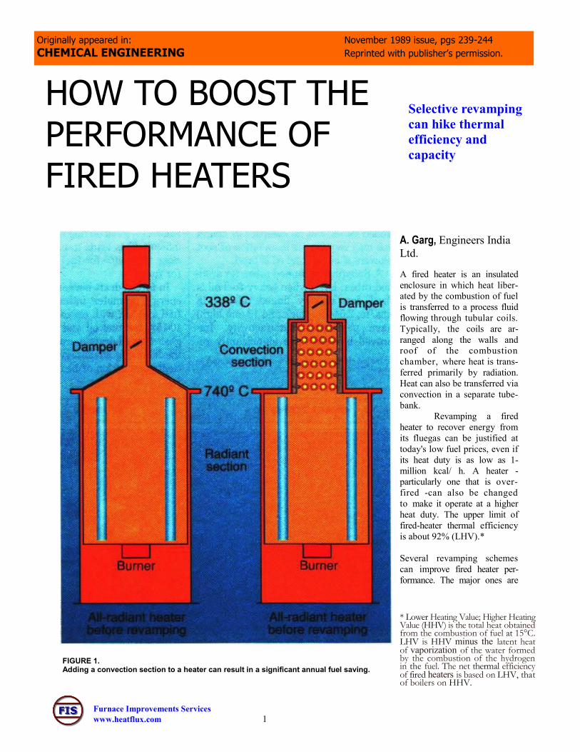
A fired heater is an insulated
enclosure in which heat liber-
ated by the combustion of fuel
is transferred to a process fluid
flowing through tubular coils.
Typically, the coils are ar-
ranged along the walls and
roof of the combustion
chamber, where heat is trans-
ferred primarily by radiation.
Heat can also be transferred via
convection in a separate tube-
bank.
Revamping a fired
heater to recover energy from
its fluegas can be justified at
today's low fuel prices, even if
its heat duty is as low as 1-
million kcal/ h. A heater -
particularly one that is over-
fired -can also be changed
to make it operate at a higher
heat duty. The upper limit of
fired-heater thermal efficiency
is about 92% (LHV).*
Several revamping schemes
can improve fired heater per-
formance. The major ones are
FIGURE 1. Adding a convection section to a heater can result in a significant annual fuel saving.
Originally appeared in: November 1989 issue, pgs 239-244
CHEMICAL ENGINEERING Reprinted with publisher’s permission.
* Lower Heating Value; Higher Heating Value (HHV) is the total heat obtained from the combustion of fuel at 15°C. LHV is HHV minus the latent heat of vaporization of the water formed by the combustion of the hydrogen in the fuel. The net thermal efficiency of fired heaters is based on LHV, that of boilers on HHV.

Furnace Improvements Services
www.heatflux.com 2
installing a convection section in an all-
radiant heater, enlarging the heat transfer
area of the convection section, converting
a natural-draft heater to a forced-draft
one, and adding air preheating or steam-
generation equipment.
Installing a convection section
Most heaters with a heat duty of up to
3 million kcal/h were built entirely as
radiant heaters. They generally have a
net thermal efficiency of from 55% to
65%, and their fluegas temperatures
range upwards from 700°C. The installa-
tion of a convection section in these heat-
ers could recover additional heat and
bring down their fluegas temperatures to
within 50-100°C of their inlet feed
temperatures. Doing this could boost
their thermal efficiencies up to 80%,
and sometimes even higher.
If the revamped heater is operated at
the same heat duty, the radiant heat flux
is reduced or additional heat duty is
extracted in the convection section.
Such an investment will normally be
paid out in two to three years.
This alteration should be preceded by a
careful checking of the heater's existing
foundation and structure to ensure that
the additional loading can be safely
borne. More space will be taken up if
an outboard convection bank (one
mounted on an independent external
structure) is added. Normally, the
height of the stack must be raised.
Sometimes, an induced-draft fan has to
be installed to overcome the extra draft
loss. Also, the pressure of the process
fluid may have to be hiked to offset the
additional tube pressure drop. A typical
all-radiant fired heater to which a con-
vection section has been added is shown
in Figure 1. Listed in Table 1 are design
and operating parameters of a vertical,
cylindrical, all-radiant, forced-draft fired
heater before and after it was retrofitted
with a convection section.
Increasing convection surface
The heat transferred to the process
fluid passing through the convection
section can be boosted by the addition of
heat-transfer surface, to reduce the
fluegas temperature to the stack to
within 50-100°C of the fluid inlet tempera-
ture. This can be done by:
1. Adding tubes. Two additional
rows of tubes can be installed in the
convection section of most heaters
without making a major change,
except for relocating the inlet piping
terminal. If space for adding
tubes has not been provided, the
convection section can be extended
into the breeching or offtake to
make space.
2. Replacing bare tubes with extended
-surface tubes, to gain more heat-
transfer area. A typical studded tube
provides 2 to 3 times more heat-
transfer area than a bare tube, and a
filmed tube 4 to 5 times as much.
Care must be exercised in the re-
vamping because extended-surface
tubes of the same size as the bare
tubes will not fit in the existing
tubesheets of the convection section.
A convection section with studded
or finned tubes will be compact in
height but may require the installa-
tion of soot blowers if heavy fuel
TABLE 2. Finned tubes provide large heat-transfer surface per unit length than do studded tubes but are more difficult to keep clean

Furnace Improvements Services
www.heatflux.com 3
oil is fired.
3. Substituting finned tubes for studded
tubes. Even when heavy fuel oil is
fired, low density finned tubes (118
fins/m, 2.54-mm thick and 19-mm
high) have performed satisfactorily.
Improved burners have significantly
reduced the formation of soot and
ash, and soot blowers can keep fin-
ned surfaces clean. Finned tubes
provide larger heat-transfer surface
than studded tubes, and cause
much less pressure drop. The char-
acteristics of the tubes are com-
pared in Table 2.
The additional heat-transfer surface in-
creases the pressure drop, and the lower
stack gas temperature reduces the
draft. The obvious remedy to the lower
draft is to resort to an induced-draft fan
or make the stack taller, or do both.
However, a load limitation may not
allow either option. In such a case, one
possibility would be to install a grade-
mounted stack or to place the convec-
tion section and stack on separate founda-
tions.
Natural to forced draft
The burners of natural-draft heaters re-quire high levels of excess air and have long flame lengths. The air pressure drop available across their registers (which control the supply of combustion air) is limited. Because the combustion air is induced at very low velocities, good mixing of air and fuel is difficult. This leads to excess air levels close to 30-40% for fuel oil and 20-25% for fuel gas. In forced-draft burners, air pressure en-ergy promotes intimate mixing of fuel and air, with excess air limited to 10-15% for fuel oil and 5-10% for fuel gas. Forced-draft burners also offer the following advantages: (1) more-efficient combustion of heavy fuel oils, (2)reduced particle emission, (3) lower consumption of atomizing steam, (4) better control of flame shape and stability, (5) less oil dripback, (6) quieter operation and (7) the possibility of preheating the combustion air.
FIGURE 2. Per
cent efficiency
improvement
per 10% reduc-
tion in excess
air.
FIGURE 3. Replacing burners may require raising the heater floor.

Furnace Improvements Services
www.heatflux.com 4
For a comprehensive exposi-tion of fired heaters, refer to the four-part series by Herbert L. Berman that appeared in the following issues of Chemical Engineering: Part I —Finding the basic design for your applica-tion, June 19, 1978, pp. 99-104; Part II — Construction materi-als, mechanical features, per-formance monitoring, July 31, 1978, pp. 87-96; Part III — How combustion conditions influ-ence design and operation, Aug. 14, 1978, pp. 129-140; and Part IV — How to reduce your fuel bill, Sept. 11, 1978, pp. 165-169. Also see Good Heater Specifications Pay Off, by A. Garg and H. Ghosh, Chem. Eng., July 18, 1988, pp. 77-80.
A 10% reduction in excess air means a 0.5 to 1.0% fuel saving, depending on the fluegas temperature (Figure 2). Ex-cess-air reduction normally results in a 2-3% fuel saving, as well as in better heat transfer. A 1 to 2% fuel saving in atomizing steam can also be realized. The total energy saving only from replacing natural-draft with forced-draft burners will not provide an eco-nomic return. However, the change can be justified when combined with such benefits as higher capacity and the elimination of flame impingement. A vacuum heater having natural-draft burners was plagued with short run lengths, chiefly due to flame impinge-ment problems and tube failures. Re-placing the burners with forced-draft ones lengthened the runs substantially (Table 8). Before replacing burners, check the heater floor elevations, because forced-draft burners require ductwork and deeper windboxes. The floor may have to be raised to accommodate the burn-ers (Figure 3). Space should also be available for ducts and fans.
Combustion air preheating
Adding an air preheater has re-
mained the most popular way of

Furnace Improvements Services
www.heatflux.com 5
Figure 6. convection section before
and after the addition of preheater.
revamping fired heaters.
Every 20°C drop in the exit
fluegas temperature boosts
efficiency by 1%. Total savings
range from 8% to 18%. An air
preheater is economically at-
tractive if the temperature of
the fluegas is higher than 350°
C. An economic justification
must take into account the cost
for fan power, as well as the
capital cost. Heat is recovered
with an existing heater by
means of a combustion air pre-
heater installed between the
convection section and the stack
(Figure 4).
A revamping entails install-
ing forced-draft burners and a
forced-draft or induced-draft fan,
or both, as well as the air prehea-
ter. Space must be available for
the preheater, fan, ducts and
dampers. The heater should be
able to operate with the heat re-
covery system bypassed. Among
the disadvantages of a preheater
is the formation of an acid mist
and, thus, faster corrosion and
more frequent maintenance,
and a higher concentration of
NOx in the fluegas.
Two types of air preheaters are
currently used with fired heaters:
the regenerative and the recu-
perative. Although the recupera-
tive preheater is larger and costlier
than the regenerative type, it is sim-
pler, requires less maintenance, re-
sists corrosion and needs no power.
Another preheater is the circulating-
liquid type (Figure 5), in which a
transfer fluid extracts heat from the
heater's convection section and heats
the combustion air passing through an
exchanger. The heater needs only
a forced-draft fan. Because the fluid
is pumped from a tank through a
closed loop, this arrangement is attrac-
tive if a hot oil circulation system al-
ready exists in a plant. For low tem-
peratures, boiler feedwater can serve
as the transfer fluid.
With the addition of a preheater, the
heater must be rerated because pre-
heating boosts the radiant heat absorp-
tion. This raises the radiant heat flux
and tubewall temperatures. Because
the flames are shorter with forced-
draft preheated-air burners, this
type of fired heater can generally be
operated (this should be checked) at
about a 10% to 25% higher duty. The
parameters of a vertical cylindrical
heater before and after being fitted
with an air preheater are listed in Ta-
ble 4.
Steam generation
Waste-heat boilers and boiler feed-
water preheaters can be an economical
solution to recovering heat from heat-
Furnace Improvements Services
www.heatflux.com 6
ers that would otherwise be
wasted. For this revision, neither a
forced-draft fan nor new burners
and controls are necessary. The
fluegas can be cooled to within 50°C
and 100°C of the inlet boiler feed-
water temperature generating me-
dium- or low-pressure steam. Cold-
end corrosion limits bringing
down the stack temperature, and
the inlet temperature of the boiler
feedwater must be controlled to
avoid the condensation of acids.
Most heaters that have a convec-
tion section can be fitted with boiler
feed-water preheaters in an ex-
tended convection section without
the need for major modification.
Frequently, an outboard convection
system with an induced-draft fan
and ducting is required for waste
-heat boilers. With pyrolysis heat-
ers and steam-naptha-reforming
heaters, waste heat boilers are
preferred because waste heat
represents a good steam source
for both.
In one instance, a revamping hiked
heater duty by 15%. The addition
of a boiler feedwater preheater
raised the thermal efficiency from
85% to 90%. The convection sec-
tion before and after revamping is
shown in Figure 6.
Recovery constraints
The presence of sulfur in a fuel
imposes a serious constraint on
the extent to which heat can be
extracted from stack gases. About
6% to 10% by weight of the sul-
fur burned in a fuel appears in
the fluegas as SO3, which con-
denses as sulfuric acid. The greater
the SO3, content in the stack gas,
the higher the dewpoint tempera-
ture.
The formation of SO3, drops
sharply with the reduction of
excess air, and rises if vanadium
is present in the fuel oil. The
tubewall temperature should be
kept at least 15°C higher than the sulfur dewpoint. A minimum temperature of
135°C is recommended with fuels having a sulfur content of less than 1%, and
150°C with fuels having 4% to 5% sulfur.
Some steps typically taken to avoid flue dewpoint corrosion are to preheat the
combustion air with low-pressure steam or hot water, to recycle part of the
hot air from the air preheater outlet to maintain a higher air inlet temperature,
and to use low-alloy corrosion-resistant steel, or a nonmetal.
References
1. Bonnet, C., Save Energy in Fired Heaters, Hydro. Proc., March 1982,
2. Cherrin n, D. C., and Michelson, H. D., How to Save Refinery Furnace Fuel," flit & Gas J, Sept. a 19'74
3. "Refinery Energy Conservation," Noyes Data Corp., Park Ridge, N.J.
4. Rijwijk, A. G., -Forced Draught Process Burners — A Case History," Du iker Frojkten BV, the Netherlands.
5. Seabold, G., How to Conserve Fuel in Furnaces and Flares, Hydro. Proc., November 1982.
Acknowledgment
The author is thankful to M. Ghosh and the management of Engineers India
Ltd. for granting permission to publish information in this article.
The author
A. Garg is deputy manager, Heat & Mass Transfer Div., Engi-neers India Ltd. (5th floor, P.T.I. Bldg.., 4, Sansad Marg, New Delhi —110 001, India). His career responsibilities have included the design, sales and commissioning of fired heaters and fur-naces. He is a chemical engineering graduate of the Indian Insti-tute of Technology.