Embed Size (px)
Citation preview
How Technologies can be used toprovide flexibility in asset
monitoring
By Daniel Stephens
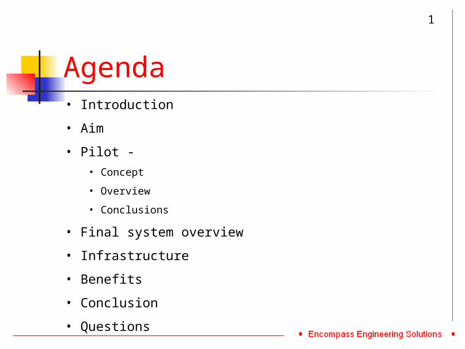
Agenda• Introduction
• Aim
• Pilot - • Concept
• Overview
• Conclusions
• Final system overview
• Infrastructure
• Benefits
• Conclusion
• Questions
1
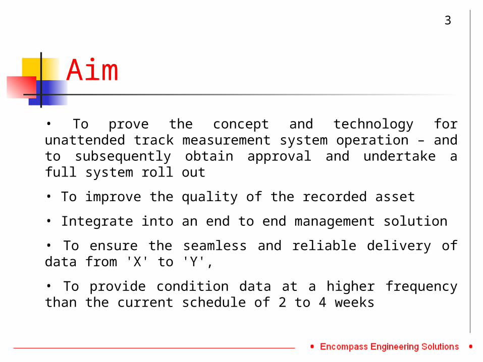
Aim
• To prove the concept and technology for unattended track measurement system operation – and to subsequently obtain approval and undertake a full system roll out
• To improve the quality of the recorded asset
• Integrate into an end to end management solution
• To ensure the seamless and reliable delivery of data from 'X' to 'Y',
• To provide condition data at a higher frequency than the current schedule of 2 to 4 weeks
3
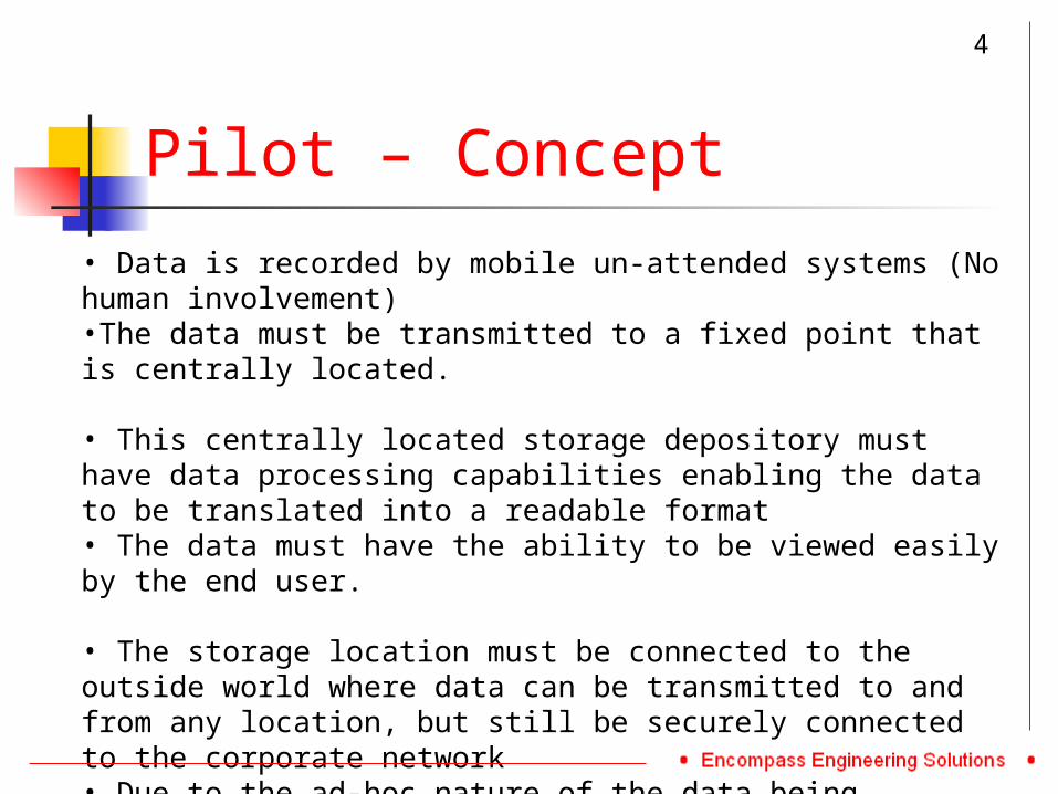
Pilot – Concept
• Data is recorded by mobile un-attended systems (No human involvement) •The data must be transmitted to a fixed point that is centrally located.
• This centrally located storage depository must have data processing capabilities enabling the data to be translated into a readable format• The data must have the ability to be viewed easily by the end user.
• The storage location must be connected to the outside world where data can be transmitted to and from any location, but still be securely connected to the corporate network• Due to the ad-hoc nature of the data being recorded, the solution should take into account that this could happen at any time of the day
4
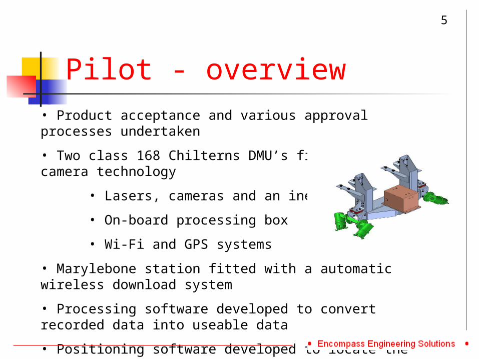
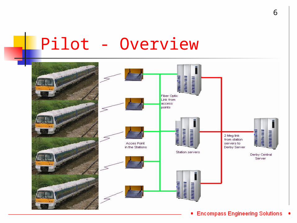
Pilot - overview• Product acceptance and various approval processes undertaken
• Two class 168 Chilterns DMU’s fitted with laser camera technology
• Lasers, cameras and an inertial box
• On-board processing box
• Wi-Fi and GPS systems
• Marylebone station fitted with a automatic wireless download system
• Processing software developed to convert recorded data into useable data
• Positioning software developed to locate the measurements
5
Pilot - Overview
6
Pilot - Conclusion
7
• The Pilot enabled us to understand how the equipment works and to provide accurate analysis of the data.
• Further work was required to integrate the end to end solution• It was identified that using a purely optical arrangement
would not provide the reliability required with the environmental conditions
• High speed performance improvements were required along with signal redundancy.
• Equipment maintenance was an issue. • Business paper was written and approved and funding
granted for roll out
Pilot - Conclusion
8
Pilot - Conclusion
9
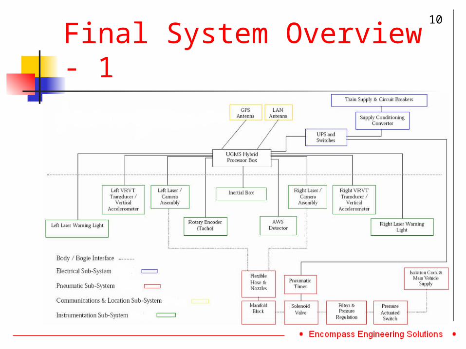
Final System Overview - 1
10
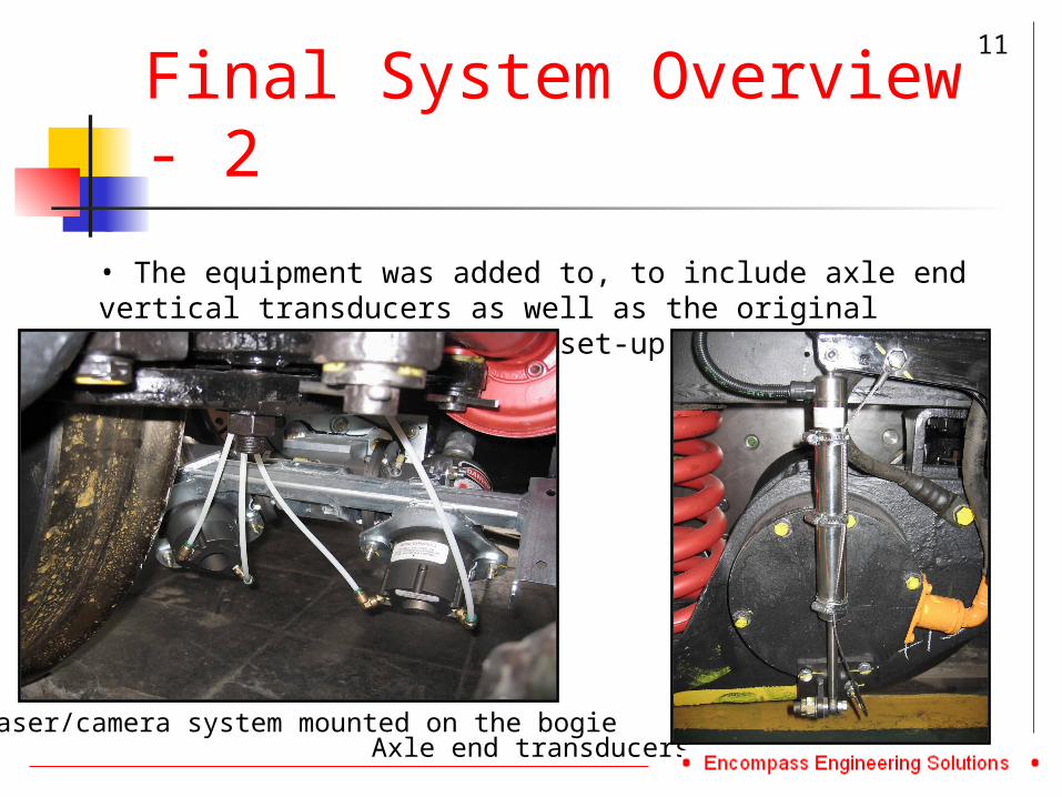
Final System Overview - 2
• The equipment was added to, to include axle end vertical transducers as well as the original laser/camera/inertial box set-up
11
Laser/camera system mounted on the bogieAxle end transducers
Final System Overview - 3
• All bogie mounted equipment is interfaced into one on-train control box with the use of GPS for positioning.• Vehicle designs were undertaken, including:
•MkIII•Class 390 – Pendilinos•168 DMU’s•UFM160
• New data processing software and infrastructure• Deployment of full Wi-Fi infrastructure in nominated stations
12
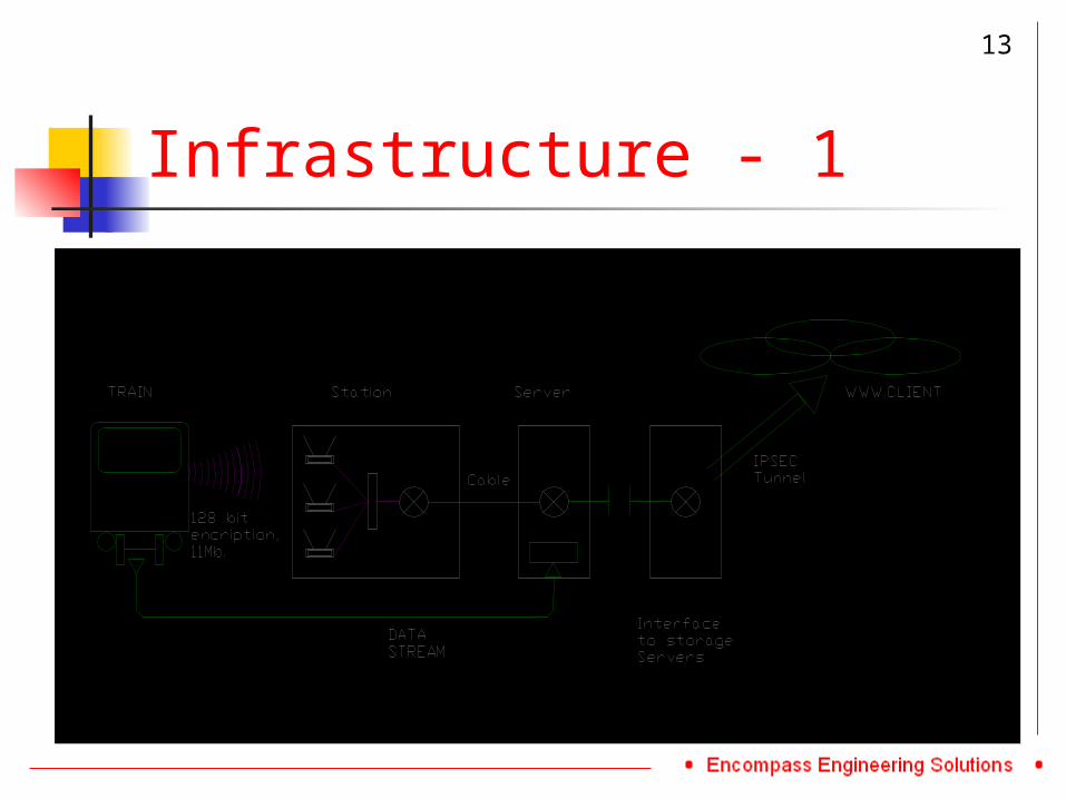
Infrastructure - 1
13
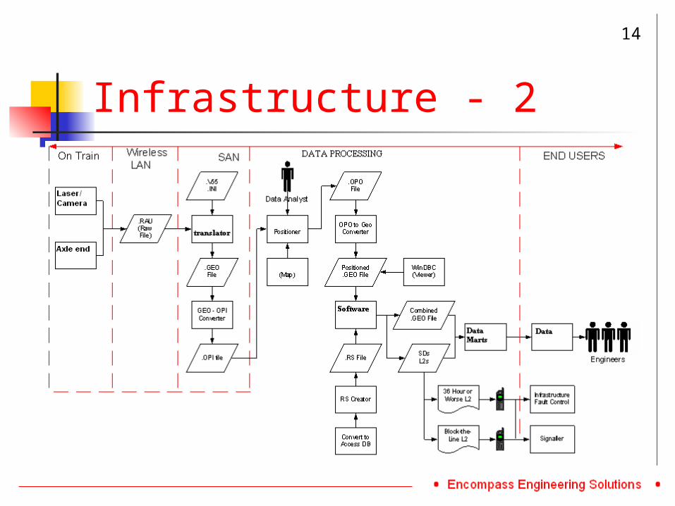
Infrastructure - 2
14
Benefits
• Increased Frequency of recording• Allows for more proactive maintenance of track• Detailed monitoring of deterioration• Targeted maintenance – correct materials, tools, personnel• Immediate feedback on maintenance effects• Predicted reduction in Level 2’s and ESR/TSR’s• Potential to look at reducing foot patrolling• Leading to ultimately a reduction in costs
15
Conclusion - 1
• To prove the concept and technology for unattended operation – and to subsequently obtain approval and undertake a full system roll out – This project was successful in this area, with the roll out nearly complete on various vehicle types and a well driven roll out plan established – slide 10 and 11.
• To improve the quality of the recorded asset – As yet to be determined, full data analysis over a period of time is required to adequately quantify this – slide 18.
• Integrate into an end to end management solution – Successful, however ongoing IT issues may delay improvements – slide 13.
16
Conclusion - 2
• To ensure the seamless and reliable delivery of data from 'X' to 'Y‘ – The movement of data and the processes in place provide a seamless movement of data, but continued issues with the maintenance of the on-train equipment and the interference on the Wi-Fi system – Slide 14.
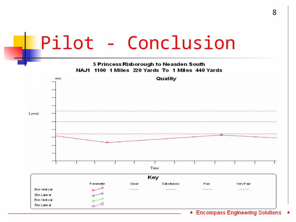
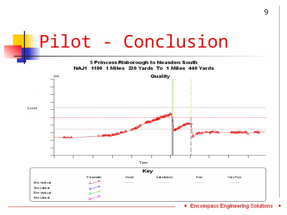
• To provide condition data at a higher frequency than the current schedule of 2 to 4 weeks – This has certainly been achieved but acceptance into the day to day maintenance regime is still yet to be achieved, increasing confidence in the data output will bring this in time – slide 8 and 9.
17
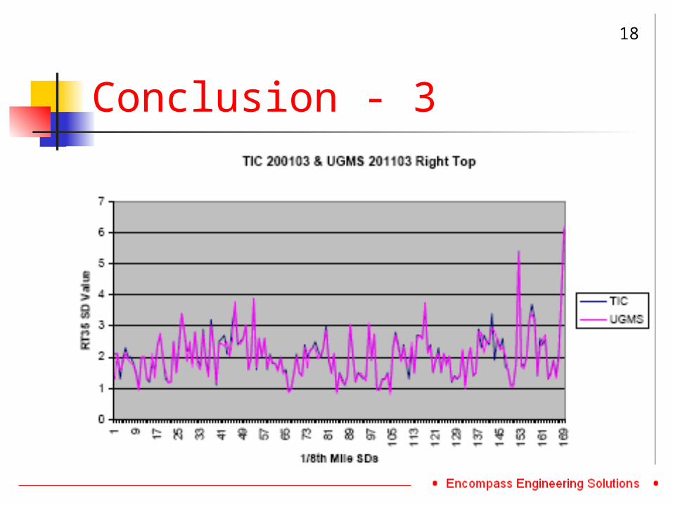
Conclusion - 3
18
Acknowledgements
• Imagemap Incorporated
• AEA Technology Rail
• Bentley Rail Systems
• Interfleet Technology
• Bombardier transportation
• Alstom
• Network Rail
• Eurailscout
• T-Mobile and Nomad
• Serco Railtest
19
References
• Diagram Slide 10. ‘UGMS Hybrid Track Geometry Measurement System Specification’, Page 6, AEATR-VTI-2003-096, Issue 3, June 2004. Andrew Hicks• Slide 15. ‘NMT and UGMS update’, Slide 10. Network Rail• Slide 5. ‘Unattended Geometry Measurement Systems’, Page 21. Network Rail• Slide 14, ‘Unattended Geometry Measurement System’, Page 35. Network Rail• Slide 18, ‘UGMS Data Validation: Progress Report 6’, Page 24, 04/02/04. Zachary Naylor
20

Questions
20
www.encompass-engineering.co.uk