Embed Size (px)
Citation preview

How Membrane Loads Influence the Modal Damping of Flexural Structures
George A. LesieutreDepartment of Aerospace Engineering
Center for Acoustics and Vibration
Sandia National Laboratories
Albuquerque, NM
September 21, 2011

Overview
• Membrane loads
• Stiffness– Vibration modes
• Frequencies, mode shapes
• Damping– Data from the literature– Model development– Results

What Are Membrane Loads?
• In a 1-D or 2-D structural member that carries lateral loads: – Forces tangent to the midsurface– “Initial stress” or “pre-stress”
• Example members– Strings, Membranes– Beams, Plates, Shells

Importance in Structural Dynamics?
• Can provide lateral restoring force
• Can affect normal vibration modes– Frequencies – Mode shapes

Sample Applications
• Rotor blades
• Airplane fuselages
• Actuators; Acoustic transducers
• MEMS resonators
Beam Example: Spinning Blade
T (x) = ρA(ξ) ξΩ2 dξ
x
L
∫
T(x)
G.S. Bir, “Structural Dynamics Verification of RCAS,” NREL/TP-500-35328, February
2005.
Variation of spinning uniform blade modal freqs with rotor speed
First coupled mode, nonuniform blade (Ω=0)
First mode, nonuniform blade (Ω=50)
“CF Load”
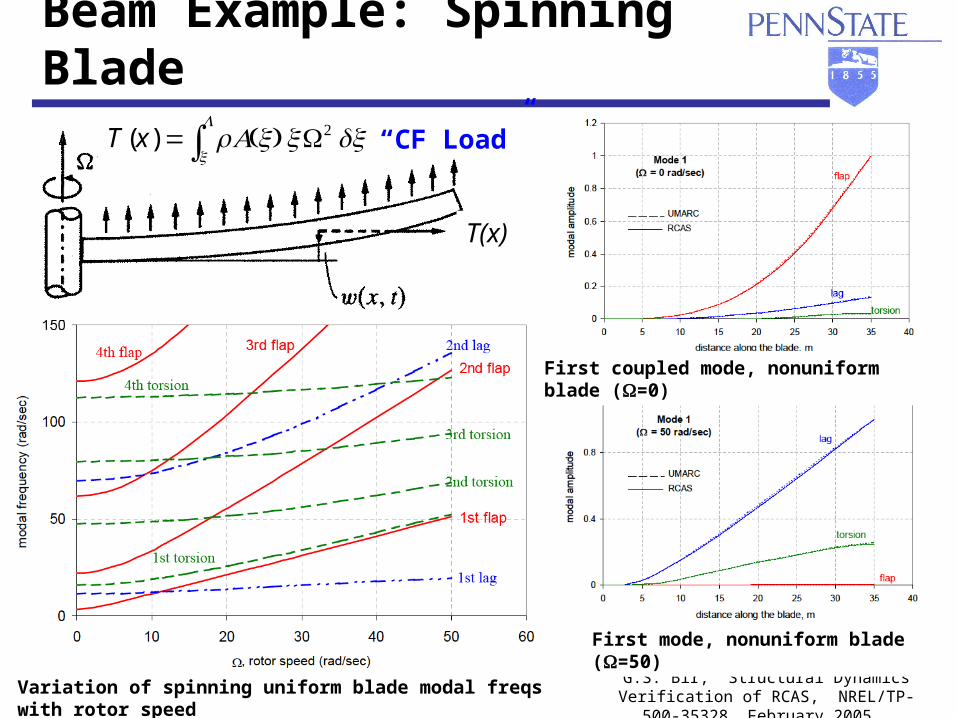
Shell Example: Airplane Fuselage
• Fuselage vibration modes – Effects of pressurization
Baker, E.H., Hermann, G., “Vibrations of Orthotropic Cylindrical Sandwich Shells under Initial Stress,” AIAA J, v 4, n 6, 1966, 1063-1070.
w(x,ϑ ,t) =Wmnsinmπx
L⎛⎝⎜
⎞⎠⎟
cos nϑ( ) cos ωt( )
u(x,ϑ ,t) =Umn cosmπx
L⎛⎝⎜
⎞⎠⎟
cos nϑ( ) cos ωt( )
v(x,ϑ ,t) =Vmnsinmπx
L⎛⎝⎜
⎞⎠⎟
sin nϑ( ) cos ωt( )
ψ x (x,ϑ ,t) = Amn cosmπ x
L⎛⎝⎜
⎞⎠⎟
cos nϑ( ) cos ωt( )
ψ ϑ (x,ϑ , t) = Bmn sinmπ x
L⎛⎝⎜
⎞⎠⎟
sin nϑ( ) cos ωt( )
transverse shear

Airplane Fuselage (continued)
• Natural freqs of thin sandwich shell
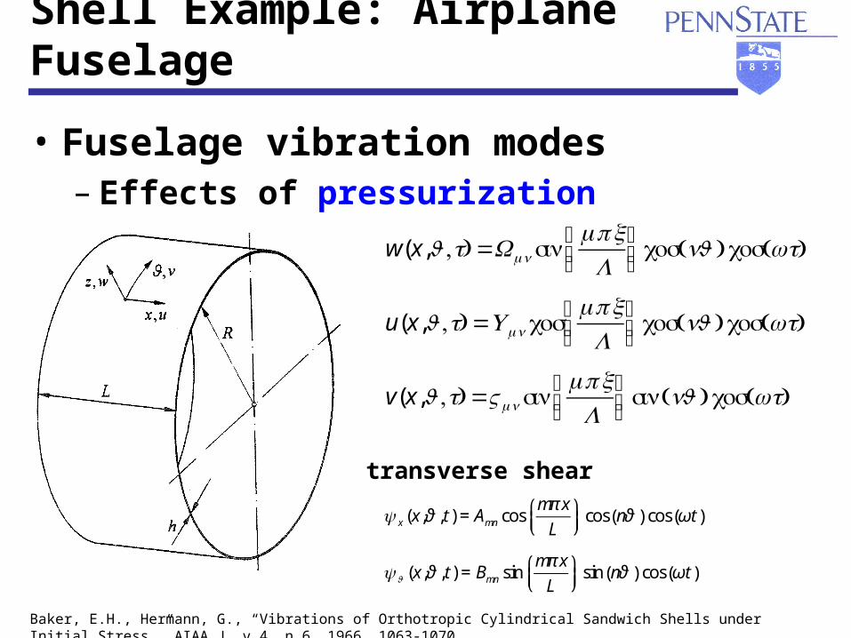
• Develop tunable piezo flexural transducers with high effective BWS product
• Use for transmission / reception of:– Frequency modulated (FM) pulses
• Short pulses for range resolution• High sweep rate for velocity resolution
• In-plane loads affect resonance
frequencies-1 -0.8 -0.6 -0.4 -0.2 0 0.2 0.4 0.6 0.8 1-1
-0.5
0
0.5
ClampedSimply supported
DiskDisk
(f(frr-f-
f r0r0)/
f)/
f r0r0
N/NcrN/Ncr
++VVDD
++
++--
--
--VVCC
VVCC
Exploitation: Tunable Transducer

More Than Frequency Shifts?
Do membrane loads affect modal damping?
If so, how?

Calculations: Fuselage Damping
• Damping of thin sandwich shell
Boeing HSCT
Lesieutre, G.A., Wodtke, H.W., Zapfe,
J.A., Damped Composite Honeycomb
Sandwich Panels for High-Speed Aircraft
Interior Noise Reduction, Final Report
to Boeing Commercial Airplane Co., June 30,
1995.

Experiments: Rotor Blade Damping
Experiments in vacuum
Smith, C.B., Wereley, N.M., “Transient analysis for damping identification in rotating composite beams with integral damping layers,” Smart Materials and Structures, v 5, 1996, 540-550.
CLD treatment
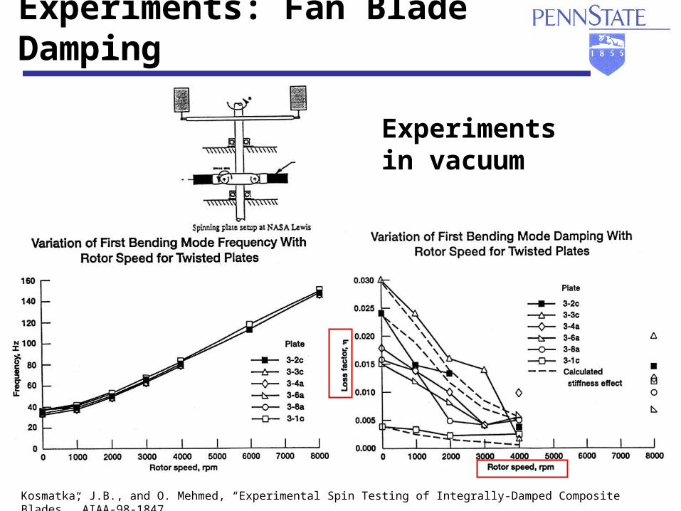
Experiments: Fan Blade Damping
Experiments in vacuum
Kosmatka, J.B., and O. Mehmed, “Experimental Spin Testing of Integrally-Damped Composite Blades,” AIAA-98-1847.

Experiments: Tunable Piezoelectric Energy Harvester
Leland, E.S. and Wright, P.K., “Resonance Tuning Of Piezoelectric Vibration Energy Scavenging Generators Using Compressive Axial Preload,” Smart Materials and Structures, 2006, pp. 1413-1420.
Lesieutre, G.A., and C.L. Davis, “Can a Coupling Coefficient of a Piezoelectric Actuator be Higher Than Those of Its Active Material?,” JIMSS, Vol. 8, 1997, pp. 859-867.
With increasing compressive preload– Resonance frequency decreases– Modal damping increases– Coupling coefficient increases
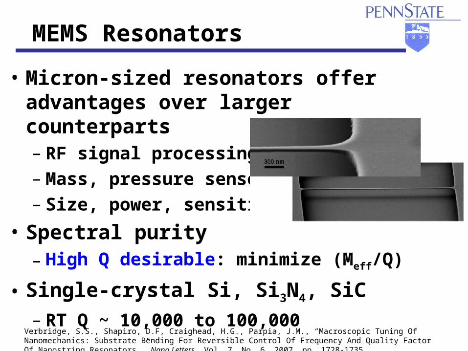
• Micron-sized resonators offer advantages over larger counterparts– RF signal processing– Mass, pressure sensor– Size, power, sensitivity
• Spectral purity– High Q desirable: minimize (Meff/Q)
• Single-crystal Si, Si3N4, SiC
– RT Q ~ 10,000 to 100,000
MEMS Resonators
Verbridge, S.S., Shapiro, D.F, Craighead, H.G., Parpia, J.M., “Macroscopic Tuning Of Nanomechanics: Substrate Bending For Reversible Control Of Frequency And Quality Factor Of Nanostring Resonators,” Nano Letters, Vol. 7, No. 6, 2007, pp. 1728-1735.

Experiments: MEMS Resonators with Tension
• High Q attributed to tensile stress– RT Q > 106 measured (in vacuum)
• The precise mechanism by which tension increases Q even in the presence of increased material damping and boundary losses “remains unknown.”
Verbridge, S.S., Shapiro, D.F, Craighead, H.G., Parpia, J.M., “Macroscopic Tuning Of Nanomechanics: Substrate Bending For Reversible Control Of Frequency And Quality Factor Of Nanostring Resonators,” Nano Letters, Vol. 7, No. 6, 2007, pp. 1728-1735.

Damping Models
• Effects of membrane loads on modal damping of flexural structures
• Viscous damping– Strain-based– Motion-based
• Complex modulus (MSE)
&&x + 2ζω &x+ω 2 x=X(t)
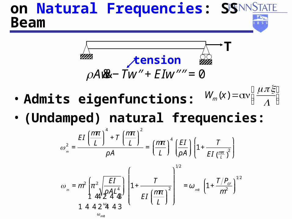
Effect of Membrane Loads on Natural Frequencies: SS Beam
• Admits eigenfunctions:
• (Undamped) natural frequencies:
T
ρA&&w − T ′′w + EI ′′′′w = 0
Wm (x) =sinmπx
L⎛⎝⎜
⎞⎠⎟
ωm
2 =EI
mπ
L⎛⎝⎜
⎞⎠⎟
4
+ Tmπ
L⎛⎝⎜
⎞⎠⎟
2
ρA=
mπ
L⎛⎝⎜
⎞⎠⎟
4EI
ρA
⎛
⎝⎜⎞
⎠⎟1+
T
EI mπL( )
2
⎛
⎝⎜
⎞
⎠⎟
tension
ωm
= m2 π 2 EI
ρ AL4
⎛
⎝⎜⎞
⎠⎟
ω0
1 244 34 4
ωm 0
1 24 4 34 4
1 +T
EImπ
L⎛⎝⎜
⎞⎠⎟
2
⎛
⎝
⎜⎜⎜⎜
⎞
⎠
⎟⎟⎟⎟
1 2
= ωm 0
1 +T Pcr
m2
⎛⎝⎜
⎞⎠⎟
1 2
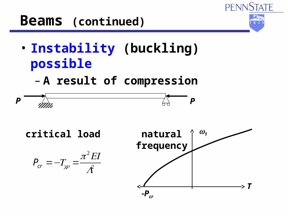
Beams (continued)
• Instability (buckling) possible– A result of compression
Pcr =−Tcr =π 2EI
L2
PP
critical load
-Pcr
T
ω1natural frequency

Effect of Membrane Loads on Damping: SS Beam (Viscous)
• Modal damping
T
ρA&&w + cs ′′′′&w − T ′′w + EI ′′′′w = 0
strain-based viscous damping
T Pcr
ζEI m =cEI
mπ
L⎛⎝⎜
⎞⎠⎟
2
2 ρ A EI( )1 2
ζ EI m 0
1 24 34
1
1+T
m2Pcr
⎛
⎝⎜⎞
⎠⎟
1 2 =ζ EI m0
1 +T Pcr
m2
⎛⎝⎜
⎞⎠⎟
1 2
−ω 2ρ A + EI(1 + i η EI
lossfactor
{ )mπ
L⎛⎝⎜
⎞⎠⎟
4
− Tmπ
L⎛⎝⎜
⎞⎠⎟
2⎡
⎣
⎢⎢⎢
⎤
⎦
⎥⎥⎥
Am* (ω ) = Fm
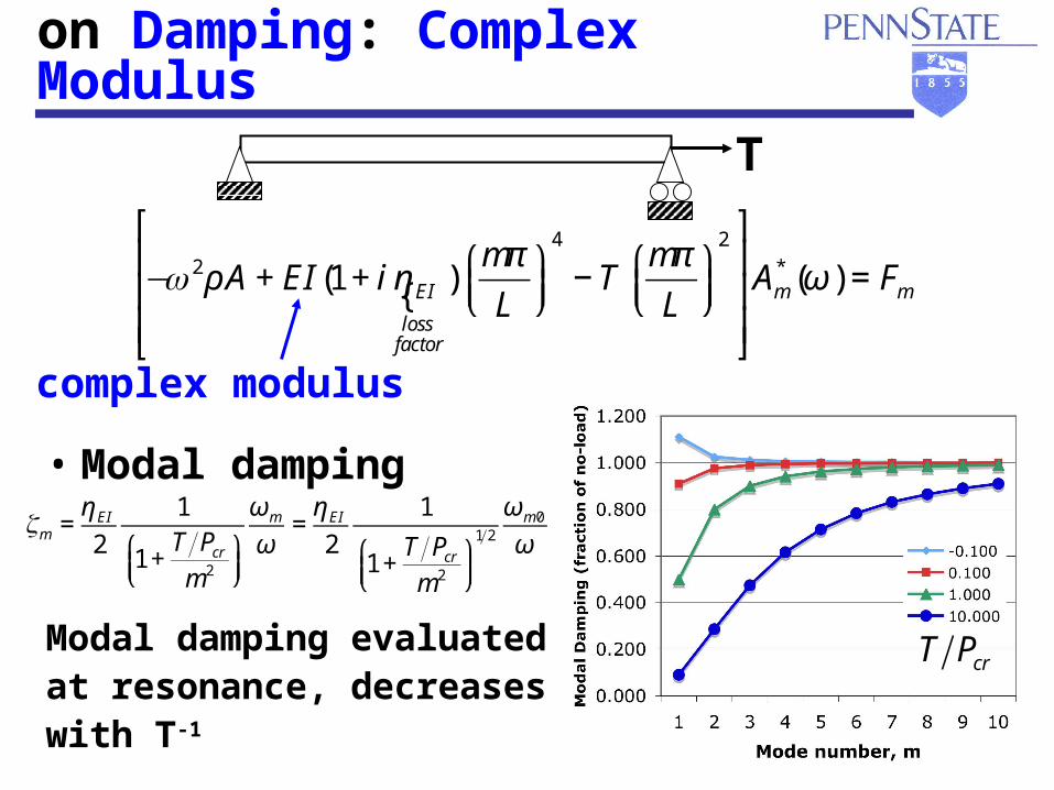
Effect of Membrane Loads on Damping: Complex Modulus
• Modal damping
Modal damping evaluatedat resonance, decreases with T-1
T
T Pcr
complex modulus
ζm =η EI
2
1
1+T Pcr
m2
⎛⎝⎜
⎞⎠⎟
ωm
ω=
η EI
2
1
1+T Pcr
m2
⎛⎝⎜
⎞⎠⎟
1 2
ωm0
ω
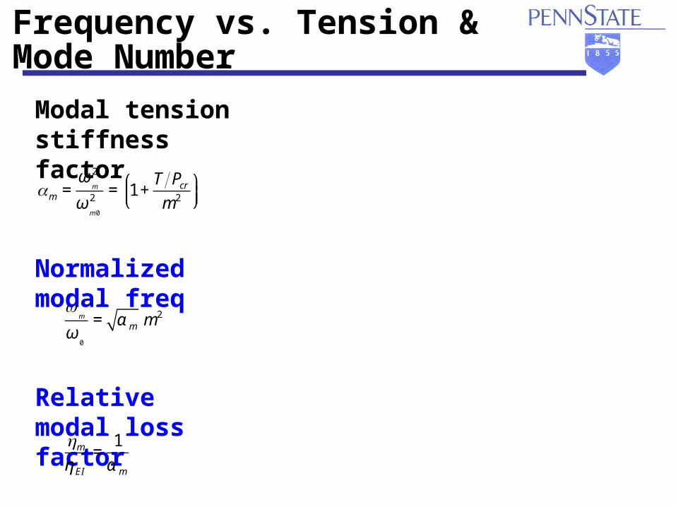
Modal Loss Factor & Frequency vs. Tension & Mode Number
Modal tension stiffness factor
Normalized modal freq
Relative modal loss factor
αm =ω
m
2
ωm 0
2= 1 +
T Pcr
m2
⎛⎝⎜
⎞⎠⎟
ωm
ω0
= α m m2
ηm
η EI
=1
α m

Good qualitative agreement of theory with experiment
Experiments: MEMS Resonators with Tension
Verbridge, S.S., Shapiro, D.F, Craighead, H.G., Parpia, J.M., “Macroscopic Tuning Of Nanomechanics: Substrate Bending For Reversible Control Of Frequency And Quality Factor Of Nanostring Resonators,” Nano Letters, Vol. 7, No. 6, 2007, pp. 1728-1735.

Insight: Modal Strain Energy
• Damping of a mode of a structure is a weighted sum of the damping of its parts– Weighting factors are the fraction of strain
(potential) energy stored in each part
ηm =Vpart
VTOTAL
⎛
⎝⎜⎞
⎠⎟m
η partparts∑ with VTOTAL( )
m= Vpart( )
mparts∑
ηm =VEI
VTOTAL
⎛
⎝⎜⎞
⎠⎟m
η EI +VT
VTOTAL
⎛
⎝⎜⎞
⎠⎟m
ηT
mat’l loss factorloss factor assoc. w/ tension = 0
=VEI
VEI + VT
⎛
⎝⎜⎞
⎠⎟m
η EI =1
1 +T Pcr
m2
⎛⎝⎜
⎞⎠⎟
η EI

Summary and Conclusions
• Membrane loads affect the apparent lateral stiffness of flexural structures– Modify normal vibration modes (freqs, shapes)
• Tensile (compressive) membrane loads decrease (increase) modal damping– Strongest effect on the lowest vibration modes– Complex modulus: modal damping decreases in
direct proportion to the increase in tension– Viscous damping: slightly different, but similar– Consistent with available experimental data
• Alternate damping approaches?
More Than Frequency Shifts!

Acknowledgments
• In addition to the cited references, students and post-docs:– Hans-Walter Wodtke– Jeff Zapfe– Chris Davis– Chad Hébert– Julien Bernard– Jeff Kauffman– Mike Thiel
• Sponsors– Boeing (HSCT), ONR, NASA/Army (RCOE)

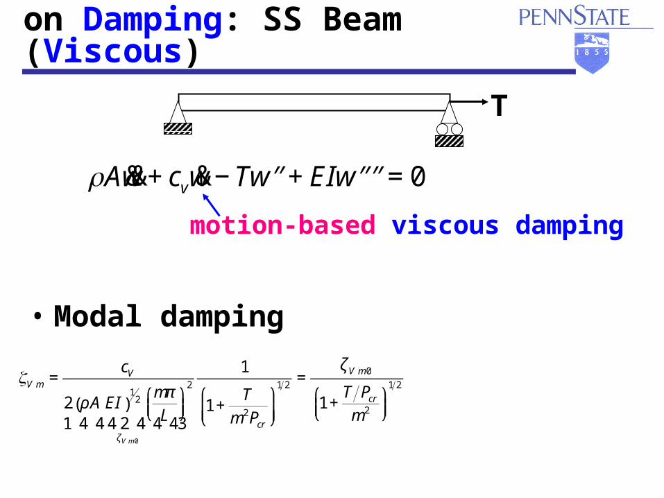
Effect of Membrane Loads on Damping: SS Beam (Viscous)
• Modal damping
T
ρA&&w + cv &w − T ′′w + EI ′′′′w = 0
motion-based viscous damping
ζV m =cV
2 ρ A EI( )1
2 mπ
L⎛⎝⎜
⎞⎠⎟
2
ζV m 0
1 24 4 4 34 4 4
1
1 +T
m2Pcr
⎛
⎝⎜⎞
⎠⎟
1 2 =ζ V m0
1 +T Pcr
m2
⎛⎝⎜
⎞⎠⎟
1 2
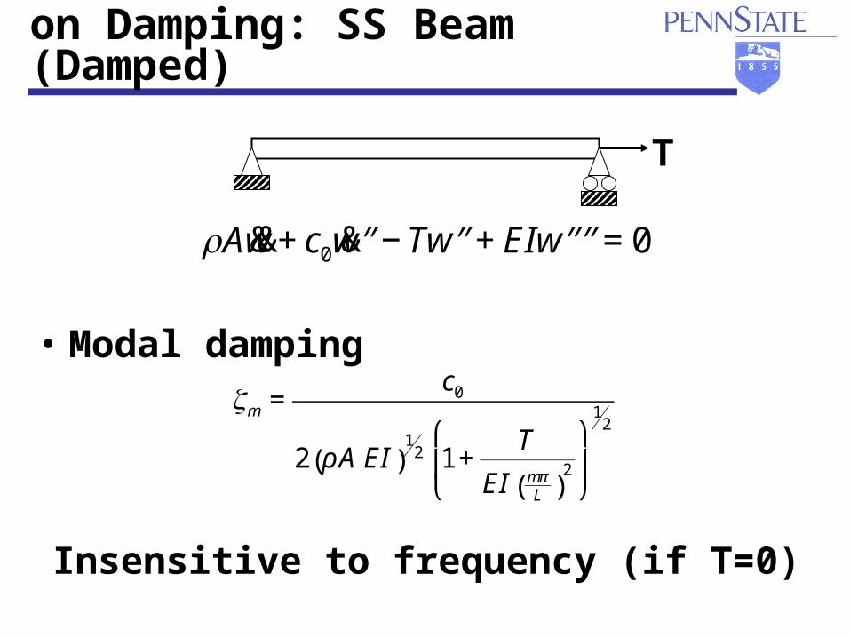
Effect of Membrane Loads on Damping: SS Beam (Damped)
• Modal damping
T
ρA&&w + c0 &′′w − T ′′w + EI ′′′′w = 0
ζm =c0
2 ρA EI( )1
2 1+T
EI mπL( )
2
⎛
⎝⎜
⎞
⎠⎟
12
Insensitive to frequency (if T=0)

Strings (1-D)
• Lateral stiffness due entirely to tension• Tension from sol’n of tangent problem
d T (x)
dx+ px(x) =0
Tangent Equilibrium
ρA(x)∂2w(x, t)
∂t 2−
∂
∂xT (x)
∂w(x, t)
∂x⎛⎝⎜
⎞⎠⎟
= pz (x, t)Lateral Eqn of Motion
Independent of lateral disps (linear)
Neglect dynamics

Membranes (2-D)
• Lateral stiffness due to membrane stress• Stress from sol’n of tangent problem
∂ N xx
∂x+
∂ N xy
∂y+ px (x, y) = 0
∂ N xy
∂x+
∂ N yy
∂y+ py (x, y) = 0
Tangent Equilibrium
ρh(x, y)∂2w
∂t 2−
∂
∂xN xx
∂w
∂x⎛⎝⎜
⎞⎠⎟
−∂
∂xN xy
∂w
∂y
⎛⎝⎜
⎞⎠⎟
−∂
∂yN xy
∂w
∂x⎛⎝⎜
⎞⎠⎟
−∂
∂yN yy
∂w
∂y
⎛⎝⎜
⎞⎠⎟
= pz (x, y, t)
Lateral Eqn of Motion
ρh∂2w
∂t 2− N ∇2 (w) = pz (x, y, t)
uniform tension
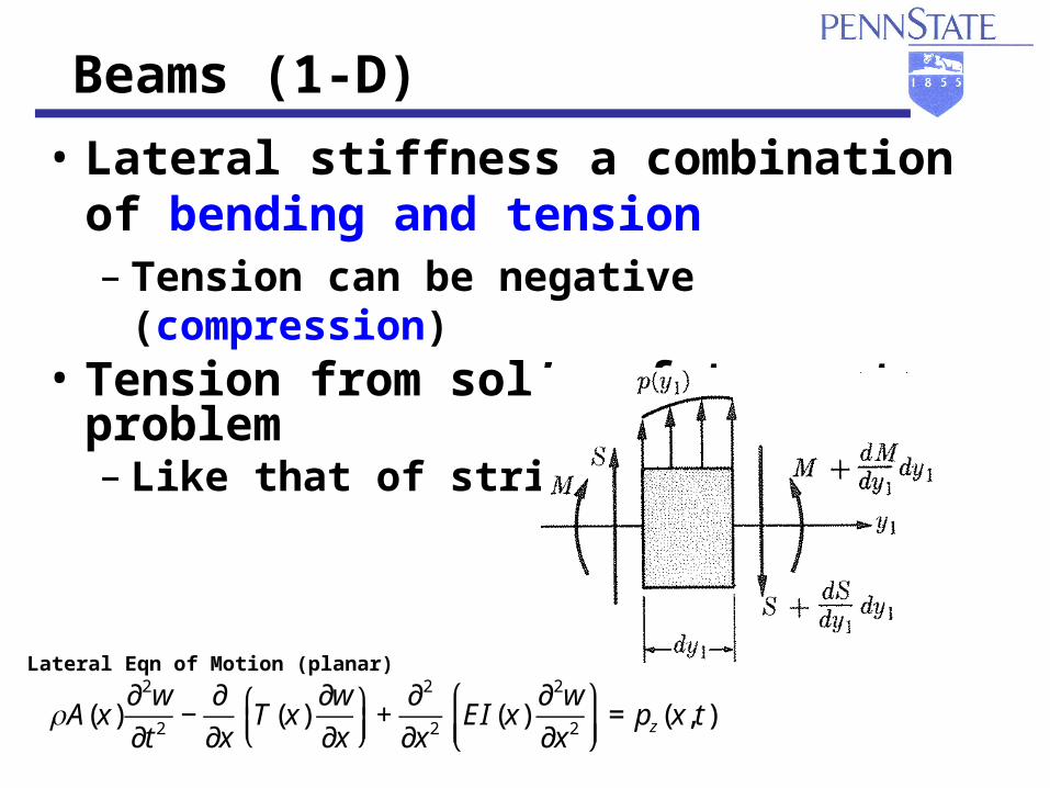
Beams (1-D)
• Lateral stiffness a combination of bending and tension– Tension can be negative (compression)
• Tension from sol’n of tangent problem– Like that of string
ρA(x)∂2w
∂t 2−
∂
∂xT (x)
∂w
∂x⎛⎝⎜
⎞⎠⎟
+∂2
∂x2EI(x)
∂2w
∂x2
⎛
⎝⎜⎞
⎠⎟= pz (x, t)
Lateral Eqn of Motion (planar)
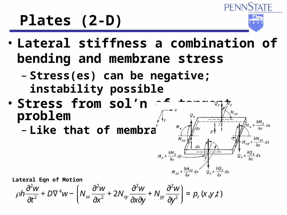
Plates (2-D)
• Lateral stiffness a combination of bending and membrane stress– Stress(es) can be negative; instability possible
• Stress from sol’n of tangent problem– Like that of membrane
ρh∂2w
∂t 2+ D∇4w − N xx
∂2w
∂x2+ 2N xy
∂2w
∂x∂y+ N yy
∂2w
∂y2
⎛
⎝⎜⎞
⎠⎟= pz (x, y, t)
Lateral Eqn of Motion
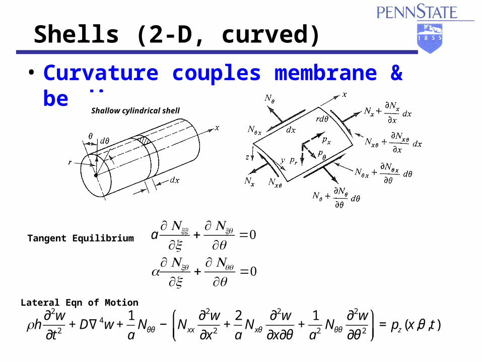
Shells (2-D, curved)
• Curvature couples membrane & bending
Shallow cylindrical shell
a∂ Nxx
∂x+
∂ Nxθ
∂θ=0
a∂ Nxθ
∂x+
∂ Nθθ
∂θ=0
Tangent Equilibrium
ρh∂2w
∂t 2+ D∇4w +
1
aNθθ − N xx
∂2w
∂x2+
2
aN xθ
∂2w
∂x∂θ+
1
a2Nθθ
∂2w
∂θ 2
⎛
⎝⎜⎞
⎠⎟= pz (x,θ , t)
Lateral Eqn of Motion

ff (Hz) (Hz)
t t (s)(s)
WDWD
– initial carrying freq: f0 = 50 Hz
– carrying freq:– instantaneous freq:
Time-Frequency Analysis of FM Pulses
• Linear FM (LFM) pulse:– amplitude: A = 1 Vpk
– duration: = 1 s– frequency sweep: f = 50 Hz
tf
ftfm
+= 0)(
tf
ftfi
+= 2)( 0
tt (s) (s)
ff (Hz) (Hz)
ff (Hz) (Hz)
tt (s) (s)
22 ππ|V
(f)|
|V(f
)|22 (
V (V
22 /Hz)
/Hz)
vv (t)
(V
)(t
) (
V)
0 0.1 0.2 0.3 0.4 0.5 0.6 0.7 0.8 0.9 1-1
0
1
40 60 80 100 120 140 1600
1
2
3x 10⁻³
40 60 80 100 120 140 1600
0.5
1

Fixed (Q = 47)
Tunable vs. Fixed-Freq Transducer
750 800 850 900 950 100010501100115012000
0.02
0.04
0.06
0.08
0.1
0.12
Frequency (Hz)
Tim
e (
s)
0 0.02 0.04 0.06 0.08 0.1 0.12 0.14-5
-4
-3
-2
-1
0
1
2
3
4
5x 10
-3
Time (s)
u(t
) (m
/s)
Tunable (Q = 47)
0 0.02 0.04 0.06 0.08 0.1 0.12 0.14-6
-4
-2
0
2
4
6x 10
-3
Time (s)u
(t)
(m/s
)
Higher, uniform output over broad range
Tuning:
Track instantaneous frequency
Bernard, J. and G.A. Lesieutre, “Design and Realization of Frequency Agile Piezoceramic Transducers,” AIAA Adaptive Structures Forum, Atlanta, GA, April 3-6, 2000.
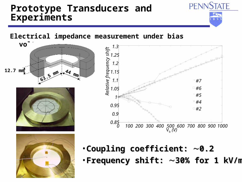
Prototype Transducers and Experiments
Electrical impedance measurement under bias voltages
• Coupling coefficient: Coupling coefficient: 0.20.2• Frequency shift: Frequency shift: 30% for 1 kV/mm30% for 1 kV/mm
0 100 200 300 400 500 600 700 800 900 10000.85
0.9
0.95
1
1.05
1.1
1.15
1.2
1.25
1.3
Vb (V)
Rel
ativ
e fr
eque
ncy
shif
t
#6
#5
#4
#2
#7
44 mm63.5 mm
12.7 mm