Embed Size (px)
Citation preview
How long is a piece of
string?
Quantifiable aspects of
Architecture Frameworks
Matthew Hause: PTC
Lars-Olof Kihlström: Syntell AB
2
Presenters
• Matthew Hause: PTC
– GTM Solutions Specialist, Fellow at PTC
– Co-Chair UPDM Group at OMG
– Member of SysML development team
– OMG Architecture Board Member
– Consultant, trainer, mentor of MBSE and Enterprise Architecture
• Lars-Olof Kihlström: Syntell AB
– Principal consultant at Syntell
– Member of the UPDM group since its inception
– Project manager for the MODAF re-engineering work that resulted in MODEM
– Member of the NAF revision syndicate (while it existed), responsible for NAF 3.0 and
3.1 on behalf of the Swedish Armed Forces
– Member of the IDEAS group (while it existed) on behalf of the Swedish Armed Forces
– Primarily engaged as mentor, coach and developer concerning model based system
engineering and enterprise architecture

3
Quantifiable aspects of MBSE and enterprise
architecture
• Model-Based Systems Engineering (MBSE) means that communication of system requirements can be improved with models rather than relying on “just words”.
• The Systems Modeling Language (SysML) was developed by INCOSE and the Object Management Group (OMG) to enable MBSE.
• It supports the specification, analysis, design, verification and validation of a broad range of systems and systems-of-systems.
• Systems engineers have been trying to get more out of their models by making them executable to answer questions or obtain results. – The greatest concentration of work on executable models has concentrated on
behavioral execution using code generation.
• This can also be done in modeling languages based on UML such as SysML and versions of the Unified Profile for DoDAF and MODAF (UPDM).

4
Is behavioral aspects all that is important?
• Behavioural aspects could be only a small part of the overall system requirements. Requirements can be non-functional, performance, structural, domain, cost, user interface, organizational, safety, interoperability and so forth. – Rather than just considering models as execution of behavior, it is important to look at
a model as a means of getting at quantitative and qualitative analysis results as well as behavioural ones.
• In order to fully grasp how different types of elements operate in different scenarios, it is important to take a look at aspects of use, performance, cost etc. from an overall point of view.
• Significant benefits can be realized by making use of architecture frameworks as a means of exploring these issues and tie the lessons learned from this into a direct MBSE development.
• In order to fully make use of quantifiable aspects a clear appreciation of what is meant is required.
5
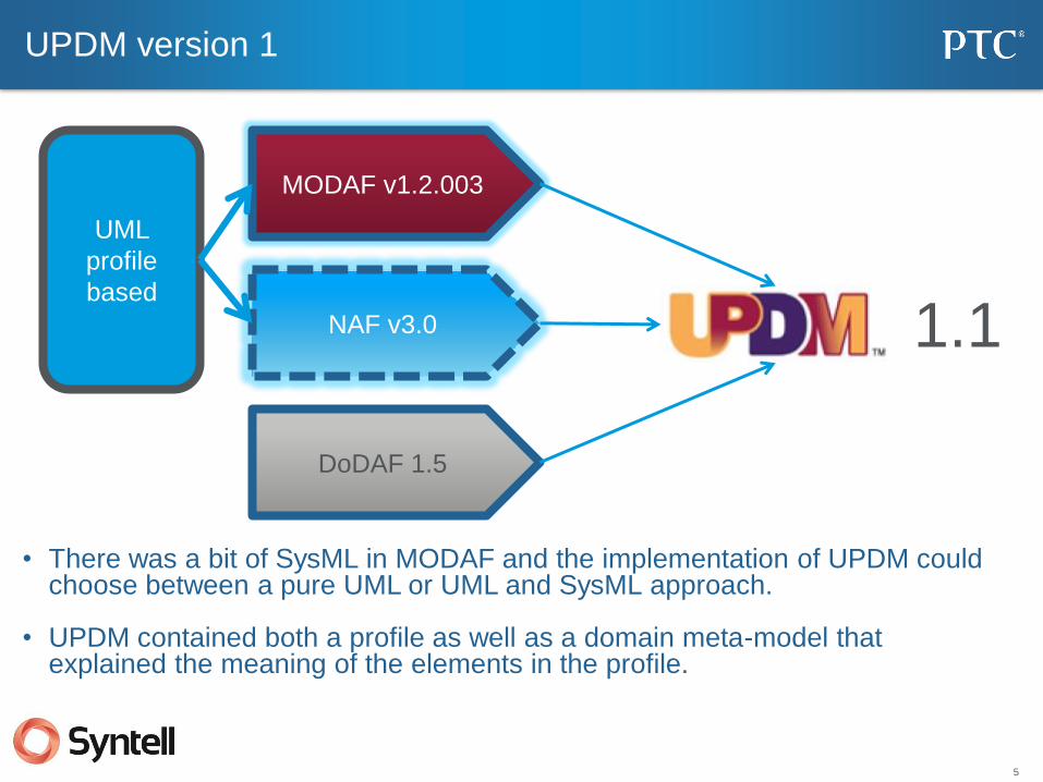
UPDM version 1
NAF v3.0
MODAF v1.2.003
DoDAF 1.5
UML
profile
based
1.1
• There was a bit of SysML in MODAF and the implementation of UPDM could choose between a pure UML or UML and SysML approach.
• UPDM contained both a profile as well as a domain meta-model that explained the meaning of the elements in the profile.
6
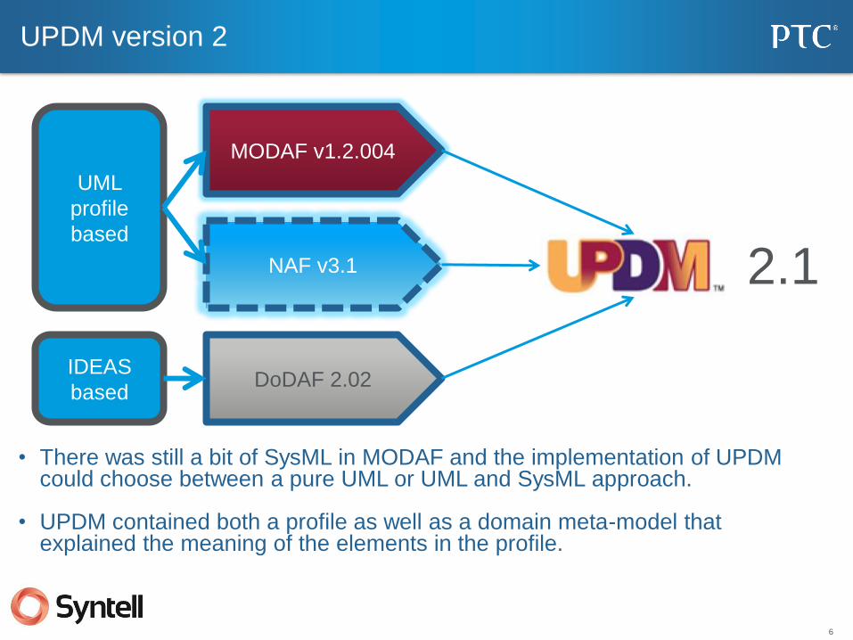
UPDM version 2
NAF v3.1
MODAF v1.2.004
DoDAF 2.02
UML
profile
based
2.1
• There was still a bit of SysML in MODAF and the implementation of UPDM could choose between a pure UML or UML and SysML approach.
• UPDM contained both a profile as well as a domain meta-model that explained the meaning of the elements in the profile.
IDEAS
based
7
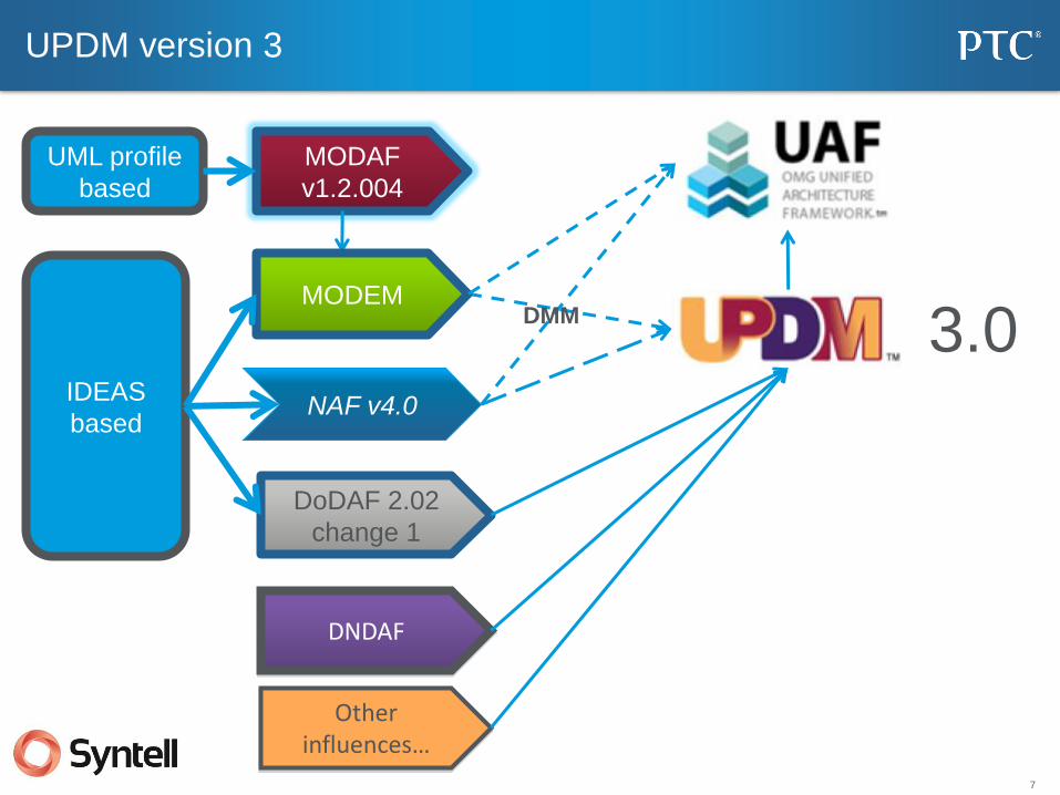
UPDM version 3
MODAF
v1.2.004
DoDAF 2.02
change 1
UML profile
based
3.0 IDEAS
based
MODEM
NAF v4.0
DNDAF
Other influences…
DMM
8
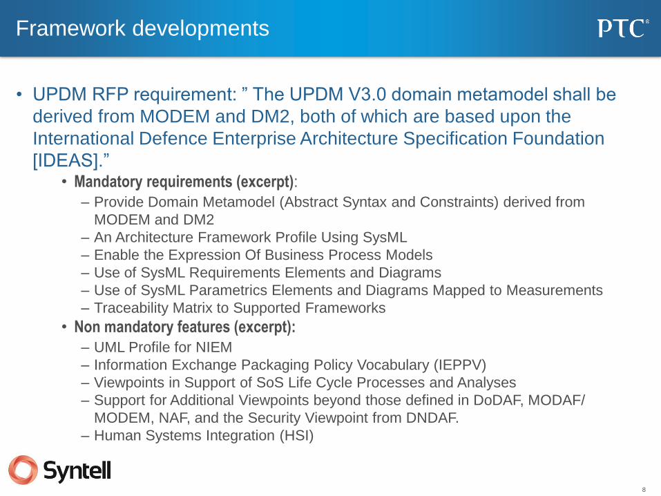
Framework developments
• UPDM RFP requirement: ” The UPDM V3.0 domain metamodel shall be
derived from MODEM and DM2, both of which are based upon the
International Defence Enterprise Architecture Specification Foundation
[IDEAS].” • Mandatory requirements (excerpt):
– Provide Domain Metamodel (Abstract Syntax and Constraints) derived from
MODEM and DM2
– An Architecture Framework Profile Using SysML
– Enable the Expression Of Business Process Models
– Use of SysML Requirements Elements and Diagrams
– Use of SysML Parametrics Elements and Diagrams Mapped to Measurements
– Traceability Matrix to Supported Frameworks
• Non mandatory features (excerpt):
– UML Profile for NIEM
– Information Exchange Packaging Policy Vocabulary (IEPPV)
– Viewpoints in Support of SoS Life Cycle Processes and Analyses
– Support for Additional Viewpoints beyond those defined in DoDAF, MODAF/
MODEM, NAF, and the Security Viewpoint from DNDAF.
– Human Systems Integration (HSI)
9
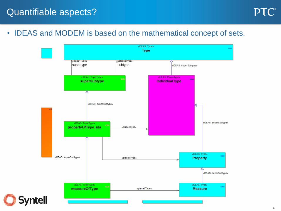
Quantifiable aspects?
• IDEAS and MODEM is based on the mathematical concept of sets.
10
An example of a categorical property and measure
11
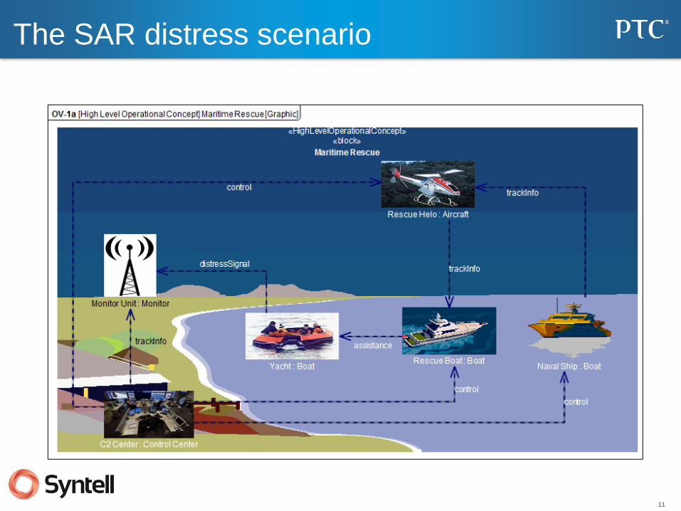
The SAR distress scenario
12
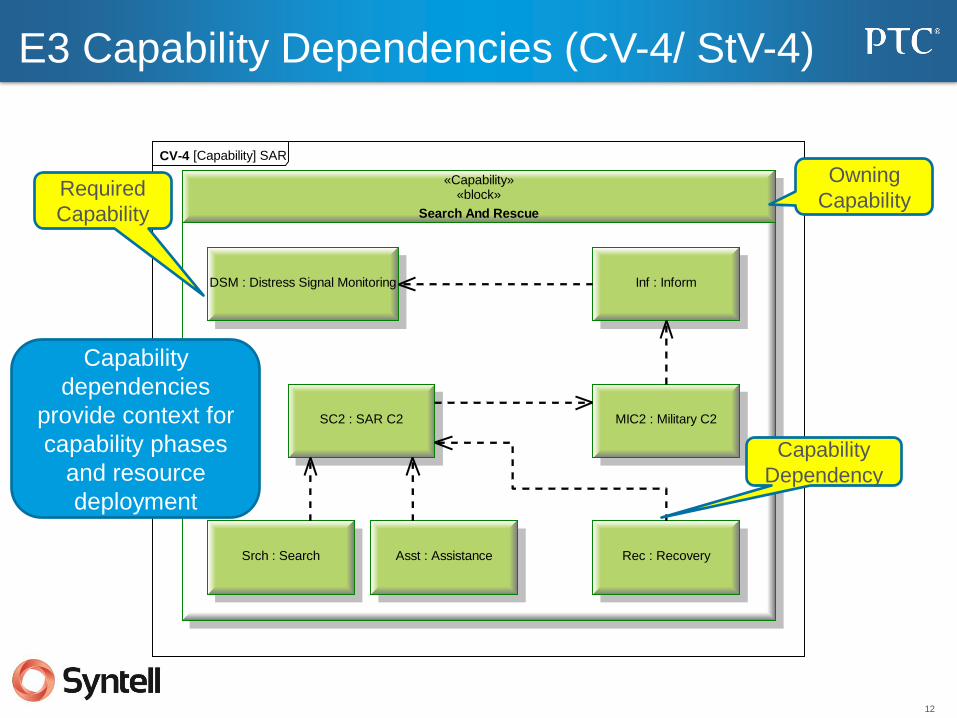
E3 Capability Dependencies (CV-4/ StV-4)
CV-4 [Capability] SAR
«Capability»«block»
Search And Rescue
DSM : Distress Signal Monitoring Inf : Inform
MIC2 : Military C2SC2 : SAR C2
Srch : Search Asst : Assistance Rec : Recovery
Required
Capability
Capability
Dependency
Capability
dependencies
provide context for
capability phases
and resource
deployment
Owning
Capability

13
MODEM Capability Dependencies
14
«Project»
startDate2010-01-01 00:00:00
endDate2010-12-01 00:00:00
responsibleResource«Organization» Department Of Transport : Government Department
SAR Manual Project I : Development
«IncrementMilestone»
endDate2010-01-01 00:00:00
resource«System» Maritime Rescue Unit v1
MRU v1 INC
«RetirementMilestone»
endDate2010-11-01 00:00:00
resource«System» Maritime Rescue Unit v1
MRU v1 OOS
«IncrementMilestone»
endDate2010-08-01 00:00:00
resource«System» Maritime Rescue Unit v2
MRU v2 INC
«RetirementMilestone»
endDate2011-05-01 00:00:00
resource«System» Maritime Rescue Unit v2
themeValuesEquipment = CompleteTraining = CompleteConcepts & Doctrine = Not ApplicablePersonnel = CompleteInformation = CompleteOrganization = CompleteInfrastructure = Not ApplicableLogistics = CompleteInteroperability = Not Applicable
MRU v2 OOS
«DeployedMilestone»
endDate2010-04-01 00:00:00
resource«System» Maritime Rescue Unit v1
usedBy«Organization» Maritime & Coastguard Agency«Organization» Volunteer Rescue Organization
MRU v1 UK DEP
«NoLongerUsedMilestone»
endDate2010-09-01 00:00:00
resource«System» Maritime Rescue Unit v1
noLongerUsedBy«Organization» Maritime & Coastguard Agency«Organization» Volunteer Rescue Organization«Organization» Coastguard
MRU v1 NLU
«DeployedMilestone»
endDate2010-07-01 00:00:00
resource«System» Maritime Rescue Unit v1
usedBy«Organization» Coastguard
MRU v1 EU DEP
«DeployedMilestone»
endDate2010-10-01 00:00:00
resource«System» Maritime Rescue Unit v2
usedBy«Organization» Maritime & Coastguard Agency«Organization» Volunteer Rescue Organization«Organization» Coastguard
MRU v2 DEP
«NoLongerUsedMilestone»
endDate2011-01-01 00:00:00
resource«System» Maritime Rescue Unit v2
noLongerUsedBy«Organization» Maritime & Coastguard Agency«Organization» Volunteer Rescue Organization«Organization» Coastguard
MRU v2 NLU
«Project»
startDate2010-06-01 00:00:00
endDate2011-02-01 00:00:00
responsibleResource«Organization» Department Of Transport : Government Department
SAR Automation Project : Development
«IncrementMilestone»
endDate2011-08-01 00:00:00
resource«System» Automated Rescue Unit v1
ARU Beta Unit INC : Development Milestone
«DeployedMilestone»
endDate2011-08-01 00:00:00
resource«System» Automated Rescue Unit v1
ARU INC : Development Milestone
«RetirementMilestone»
endDate2012-01-01 00:00:00
resource«System» Automated Rescue Unit v1
themeValuesEquipment = CompleteTraining = CompleteConcepts & Doctrine = Not ApplicablePersonnel = CompleteInformation = CompleteOrganization = CompleteInfrastructure = Not ApplicableLogistics = CompleteInteroperability = Not Applicable
ARU OOS : Development Milestone
«Project»
startDate2010-08-01 00:00:00
endDate2011-05-28 00:00:00
responsibleResource«Organization» Department Of Transport : Government Department
SAR Manual Project II : Development
«MilestoneSequence»
«ProjectSequence»
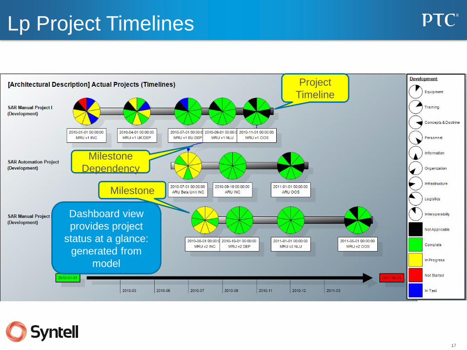
PV-3 [Architectural Description] Actual Projects
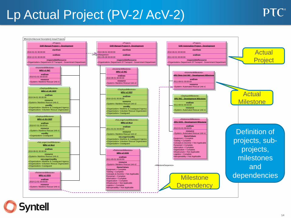
Lp Actual Project (PV-2/ AcV-2)
Actual
Milestone
Milestone
Dependency
Actual
Project
Definition of
projects, sub-
projects,
milestones
and
dependencies

15
Lp Project Detail (PV-2/ AcV-2)
«DeployedMilestone»
endDate2010-04-01 00:00:00
resource«System» Maritime Rescue Unit v1
usedBy«Organization» Maritime & Coastguard Agency«Organization» Volunteer Rescue Organization
themeValuesEquipment = CompleteTraining = In TestConcepts & Doctrine = In ProgressPersonnel = CompleteInformation = In ProgressOrganization = CompleteInfrastructure = CompleteLogistics = Not ApplicableInteroperability = In Progress
MRU v1 UK DEP
«Project»
startDate2010-01-01 00:00:00
endDate2010-12-01 00:00:00
responsibleResource«Organization» Department Of Transport : Government Department
SAR Manual Project I : Development
Milestone
Project
Theme
Statuses
Resource
Resource
Used By
Organization/
Person
Responsible
16
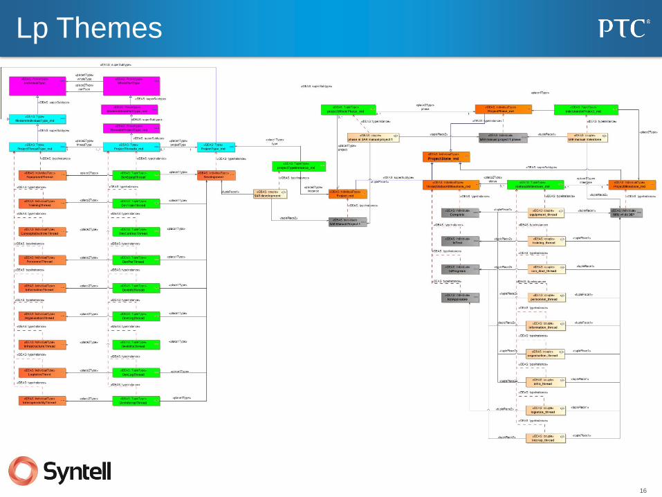
Lp Themes
17
Lp Project Timelines
Project
Timeline
Milestone
Dependency
Milestone
Dashboard view
provides project
status at a glance:
generated from
model

18
AV-3 Measurements Definitions
AV-3 [Architectural Description] Measurements (Class)
«MeasurementSet»«valueType»
Maritime SAR Measurements
«Measure» seaConditions : Sea State
«MeasurementSet»«valueType»
Land SAR Measurements
«Measure» terrain : Terrain Type
«MeasurementSet»«valueType»
Standard SAR Measurements
«Measure» areaCoverage : Coverage
«Measure» findTime : Elapsed Time
«Measure» persistence : Elapsed Time
«Measure» searchCoverage : Coverage
«Measure» weatherConditions : Weather Conditions
Measurement
Set
Measurements
Measurement
Sub-Type
Definition of
metrics for
reuse
throughout the
architecture.

19
AV-3 Actual Measurements
• Specific metric values
«ActualMeasurementSet»{intention = Estimate}
Initial Values : Maritime SAR Measurements
seaConditions : Sea State = Sea State 6
areaCoverage : Coverage = 500
findTime : Elapsed Time = <8 hours
persistence : Elapsed Time = >15 hours
searchCoverage : Coverage = 400
weatherConditions : Weather Conditions = Heavy Rain
«ActualMeasurementSet»{intention = Required}
Required Values : Maritime SAR Measurements
seaConditions : Sea State = Sea State 8
areaCoverage : Coverage = 600
findTime : Elapsed Time = <5 hours
persistence : Elapsed Time = >20 hours
searchCoverage : Coverage = 500
weatherConditions : Weather Conditions = Stormy
«ActualMeasurementSet»{intention = Result}
Final Values : Maritime SAR Measurements
seaConditions : Sea State = Sea State 8
areaCoverage : Coverage = 650
findTime : Elapsed Time = <4 hours
persistence : Elapsed Time = >20 hours
searchCoverage : Coverage = 550
weatherConditions : Weather Conditions = Stormy
«ActualMeasurementSet»{intention = Estimate}
intentionEstimate
UPDM : Standard SAR Measurements
areaCoverage : Coverage = 10
findTime : Elapsed Time = 20
persistence : Elapsed Time = 50
searchCoverage : Coverage = 60
weatherConditions : Weather Conditions = 70
AV-3 [Architectural Description] Measurements (Actual)
Actual
Measurement
Measurement
Values

20
Ep Capability Phasing (Fragment) (CV-3/ StV-3)
Timeline
Capabilities
Capability
Metrics
Realizing
Resource
Coverage Summarizes how and
when capabilities will
be realized as well as
metrics. Identifies
capability gaps.
Capability Gap
21
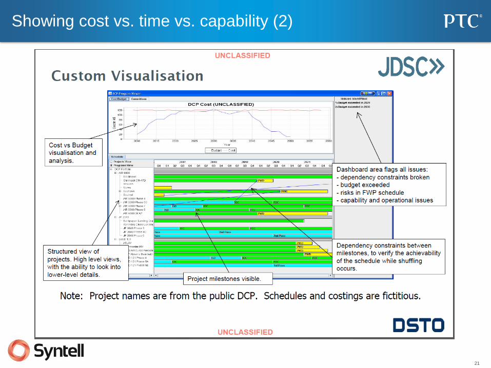
Showing cost vs. time vs. capability (2)
• Pres
22
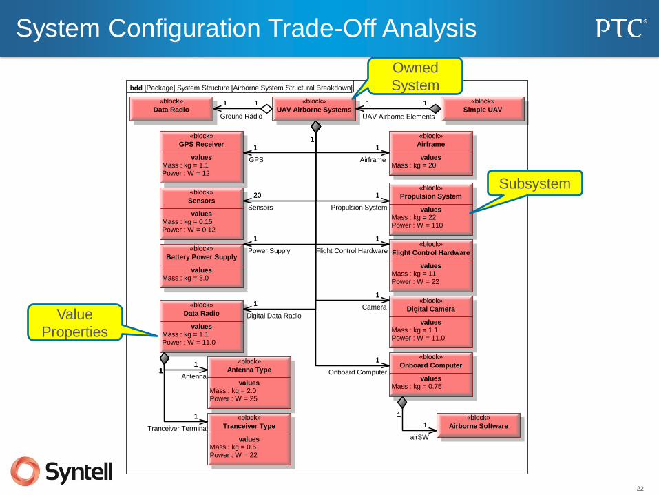
System Configuration Trade-Off Analysis
1
1
11
1
1
1 1
1
1
1 1
1
1
1
1
1
1
1
1
1
1
1
1
1
1
20
1
bdd [Package] System Structure [Airborne System Structural Breakdown]
«block»
valuesMass : kg = 20
Airframe
«block»
valuesMass : kg = 22Power : W = 110
Propulsion System
«block»
valuesMass : kg = 11Power : W = 22
Flight Control Hardware
«block»
valuesMass : kg = 0.75
Onboard Computer
«block»
valuesMass : kg = 1.1Power : W = 11.0
Digital Camera
«block»
valuesMass : kg = 1.1Power : W = 12
GPS Receiver
«block»
valuesMass : kg = 0.15Power : W = 0.12
Sensors
«block»
valuesMass : kg = 3.0
Battery Power Supply
«block»
Airborne Software
«block»
Simple UAV
«block»
Data Radio
«block»
valuesMass : kg = 2.0Power : W = 25
Antenna Type
«block»
valuesMass : kg = 0.6Power : W = 22
Tranceiver Type
«block»
valuesMass : kg = 1.1Power : W = 11.0
Data Radio
«block»
UAV Airborne Systems
1
1
Power Supply
11
Antenna
1
1
Tranceiver Terminal
1 1
UAV Airborne Elements
1
1
airSW
1 1
Ground Radio
1
1
Airframe
1
1
Propulsion System
1
1
Flight Control Hardware
1
1
Onboard Computer
1
1
Camera1
1
Digital Data Radio
1
1
GPS
20
1
Sensors
Value
Properties
Subsystem
Owned
System
23
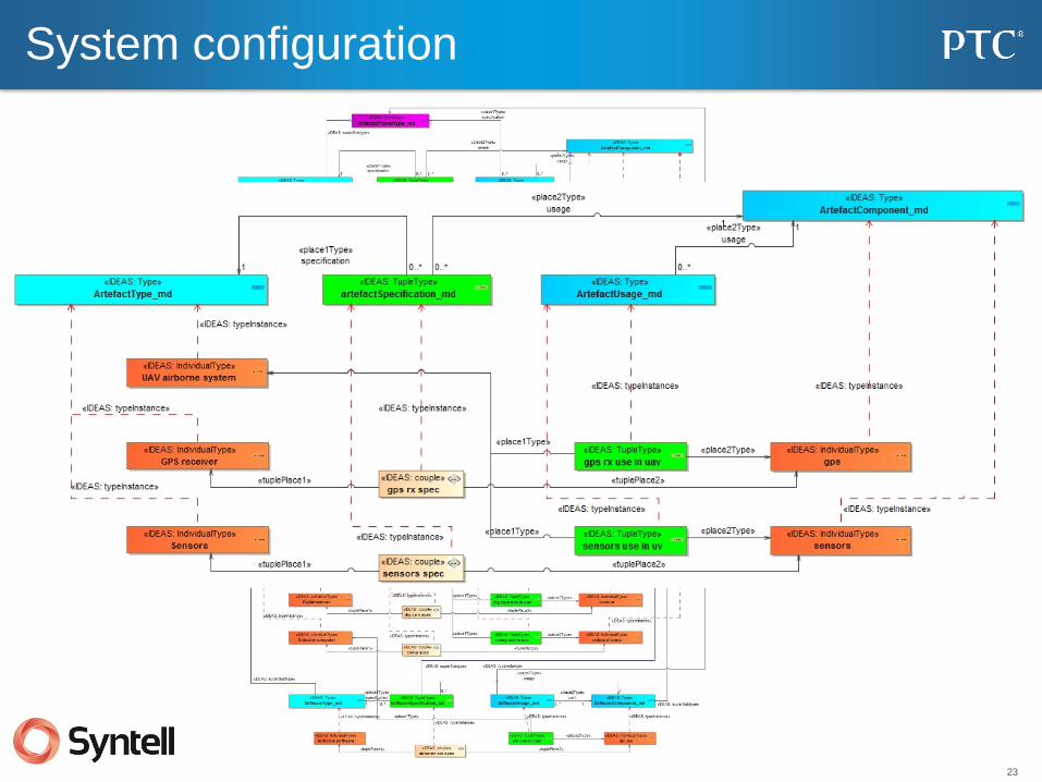
System configuration
24
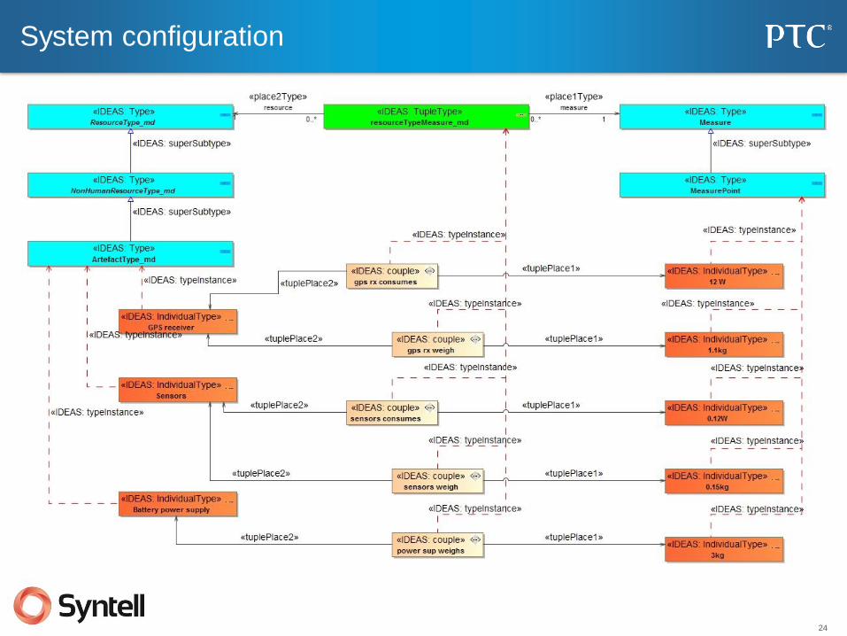
System configuration
25
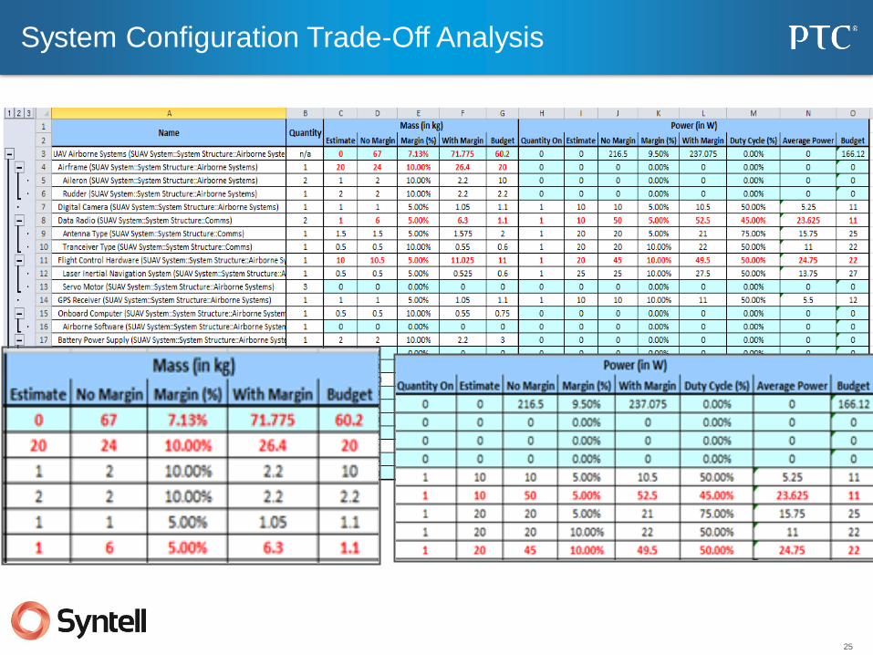
System Configuration Trade-Off Analysis
26
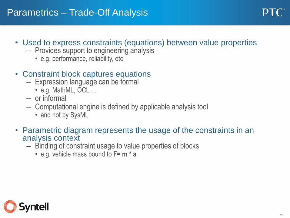
Parametrics – Trade-Off Analysis
• Used to express constraints (equations) between value properties – Provides support to engineering analysis
• e.g. performance, reliability, etc
• Constraint block captures equations – Expression language can be formal
• e.g. MathML, OCL … – or informal – Computational engine is defined by applicable analysis tool
• and not by SysML
• Parametric diagram represents the usage of the constraints in an analysis context – Binding of constraint usage to value properties of blocks
• e.g. vehicle mass bound to F= m * a

27
11
1
1
1
1
1
111
bdd [Package] Parametrics
«block»
valuesconditions : Sea StatetotalArea : SquareMiles
MarineEnvironment
«block»
valuesmeanResponseTime : HoursrescueTime : HourssearchTime : Hours
MeanResponseTimeAnalysis
«block»
valuesscanWidth : Milesspeed : MilesPerHour
Aircraft
«block»
valueslocationXY : Miles [2]speed : MilesPerHour
Boat
«block»
valuessignalResponseTime : Hours
CommandCenter
11
helicopter
1
1
sea
1
1
yacht1
1
lifeboat
11
command
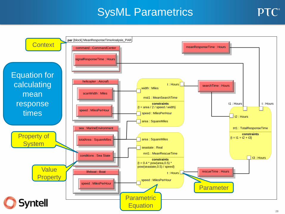
SysML Parametrics – Mean Response Time
Context
Aircraft
Values
Environmental
Values Boat and Yacht
Values
BDD for
Mean
Response
Time
Analysis
Command
Center Values
28
par [block] MeanResponseTimeAnalysis_PAR
meanResponseTime : Hourscommand : CommandCenter
signalResponseTime : Hours
helicopter : Aircraft
scanWidth : Miles
speed : MilesPerHour
lifeboat : Boat
speed : MilesPerHour
sea : MarineEnvironment
conditions : Sea State
totalArea : SquareMiles
mst1 : MeanSearchTime
constraints{t = area / 2 / speed / width}
area : SquareMiles
speed : MilesPerHour
t : Hours
width : Miles
rescueTime : Hours
searchTime : Hours
mrt1 : MeanRescueTime
constraints{t = 0.4 * pow(area,0.5) *pow(seastate,0.5) / speed}
area : SquareMiles
seastate : Real
speed : MilesPerHour
t : Hours
trt1 : TotalResponseTime
constraints{t = t1 + t2 + t3}
t : Hourst1 : Hours
t2 : Hours
t3 : Hours
SysML Parametrics
Context
Parametric
Equation
Value
Property
Parameter
Property of
System
Equation for
calculating
mean
response
times
29
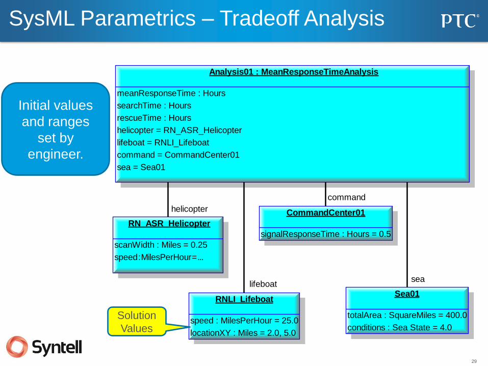
Analysis01 : MeanResponseTimeAnalysis
meanResponseTime : Hours
searchTime : Hours
rescueTime : Hours
helicopter = RN_ASR_Helicopter
lifeboat = RNLI_Lifeboat
command = CommandCenter01
sea = Sea01
RN_ASR_Helicopter
scanWidth : Miles = 0.25
speed : MilesPerHour = ...
RNLI_Lifeboat
speed : MilesPerHour = 25.0
locationXY : Miles = 2.0, 5.0
CommandCenter01
signalResponseTime : Hours = 0.5
Sea01
totalArea : SquareMiles = 400.0
conditions : Sea State = 4.0
helicopter
lifeboat
command
sea
SysML Parametrics – Tradeoff Analysis
Solution
Values
Initial values
and ranges
set by
engineer.
30
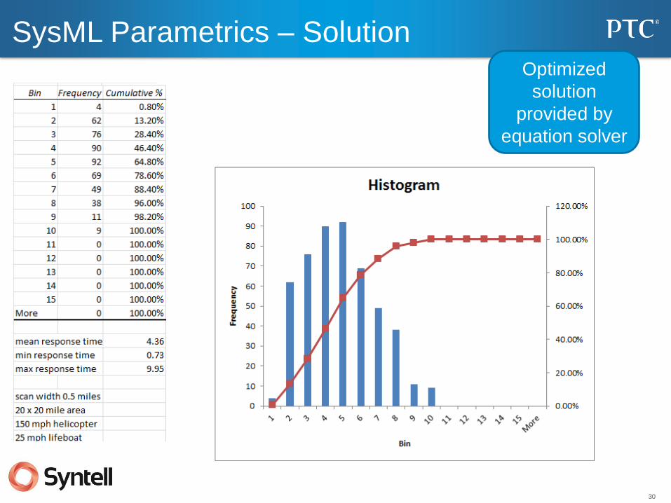
SysML Parametrics – Solution Optimized
solution
provided by
equation solver

31
L2 Operational Nodes (Performers) (OV-2)
Context
Node
Operational
nodes with
needlines and
flows
Flow

32
L3 Operational Resource Flow Matrix (Fragment) (OV-3)
Overlap
Ov-2
Overlap
Type DIV-2
Producing
Performer
OV-2 Producing
Activity OV-5
Connection
OV-2
Consuming
Performer
OV-2
Consuming
Activity OV-5
Generated
automatically
from the
architecture
33
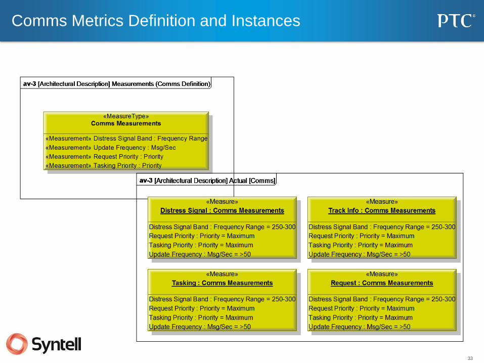
Comms Metrics Definition and Instances
34
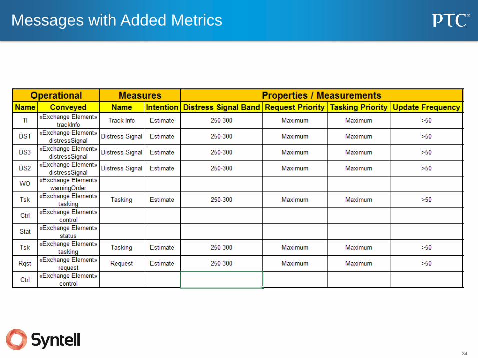
Messages with Added Metrics
35
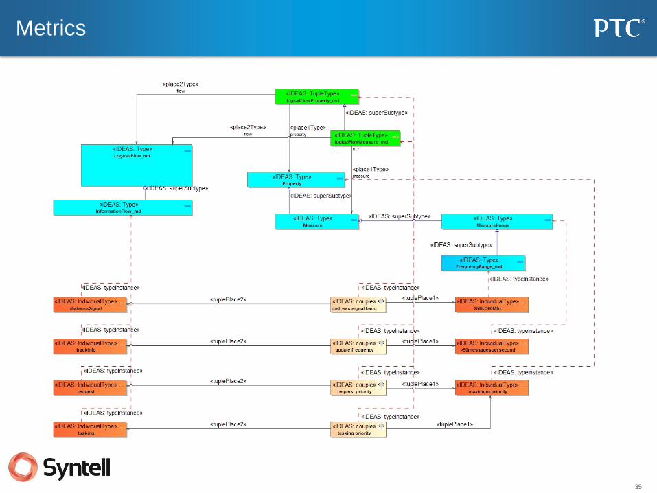
Metrics
36
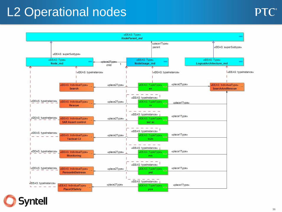
L2 Operational nodes
37
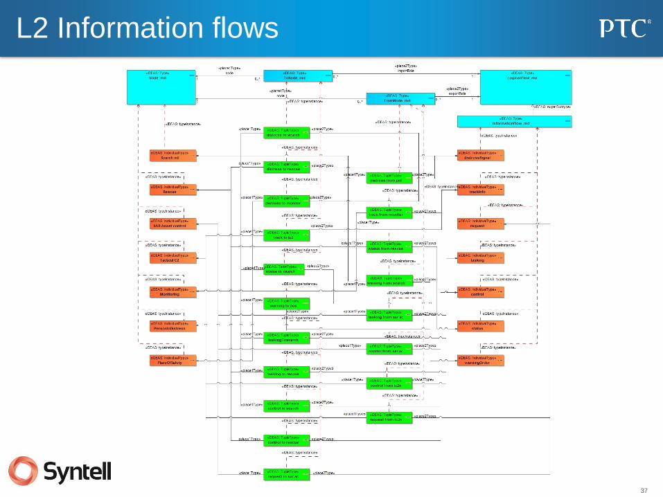
L2 Information flows

38
Conclusions
• The purpose of a model is to answer one or more questions
– Before you start, agree on the question
• Assessment criteria should be agreed prior to starting the model
• A well-documented process is essential for success
• Executable architectures should look at more than just behavior.
• Executing an architecture requires data
– (You can’t execute a PowerPoint slide.)
• In order to ensure that the data is semantically correct a “wash” through
an IDEAS based ontology is a good idea.
39
Questions, Comments, Discussion