Embed Size (px)
Citation preview

EY-RC 504/505: Room automation station, ecos504/505
How energy efficiency is improvedPowerful function modules in the ecos504/505 integrate the regulation of the room temperature, light-ing and sunshading to create a comfortable room climate with minimum energy consumption.
Features• Part of the SAUTER EY-modulo 5 system family• Modular room automation station for up to 8 rooms or 8 flexible room segments• BACnet/IP communication (EN ISO 16484-5) as BACnet Building Controller (B-BC)• The ecoUnit 3 (EY-RU 3**) and ecoUnit 1 (EY-RU 1**) room operating units enable individual ad-
justment of the room climate• Optimises energy consumption thanks to presence function, window contact monitoring, demand-
controlled ventilation, control of lighting and window blinds, and time-dependent setpoint specifica-tion
• Function libraries for climate, lighting and sunshading• Expansion bus for remote ecoLink modules, ecoUnit room operating units and EnOcean wireless
interface• KNX interface to connect KNX operating devices, sensors and actuators• Integrated KNX tunnelling function (KNX/IP) for the commissioning of KNX with ETS• DALI interface with DALI bus power supply for the connection of DALI electronic ballasts (EB) and
DALI sensors• Web-based commissioning tool for DALI network• SMI interface (SMI/SMI LoVo) for activating SMI motors for sunshading (window blinds, roller shut-
ters)• Integrated tunnelling function for commissioning with SMI-easyMonitor• Time programme and calendar function; data recording• Integrated moduWeb web server (only EY-RC504F101)• Engineering/programming using CASE Suite (based on IEC 61131-3)• Integration into the building management system via BACnet/IP with Ethernet interface
Technical data
Power supplyPower supply 24 V= ±10%
24 V~ +25%/-15%, 48...63 HzCurrent consumption EY-RC504F**1: max. 0.33 A
EY-RC504F021: max. 0.43 AEY-RC 505 (without DALI): max.0.33 AEY-RC 505 (with DALI): max. 0.61 A
Max. peak inrush current 13 A (10 ms)Power consumption EY-RC504F**1: 4 W/8 VA; typ. 2.5 W
EY-RC504F021: max. 6 W/10 VAEY-RC 505 (without DALI): 4 W/8 VAEY-RC 505 (with DALI): max. 9 W/14VA
Connection Spring-type terminals0.2...2.5 mm2 rigid/flexibleAmpacity max. 5 A
Ambient conditionsOperating temperature 0...45 °CStorage and transport temperature -25...70 °CAdmissible ambient humidity 10...85% rh, no condensation
FunctionBACnet BACnet data point objects 600 (incl. HW)
Control 32 (Loop)Active COV subscription 1500BACnet client links 200 (Peer-to-Peer)
Dynamic objects Time programmes 32 (Schedule)Calendar 16 (Calendar)
Product data sheet 7.1 94.112
Right of amendment reserved © 2018 Fr. Sauter AG 1/17
EY-RC 504
EY-RC 505
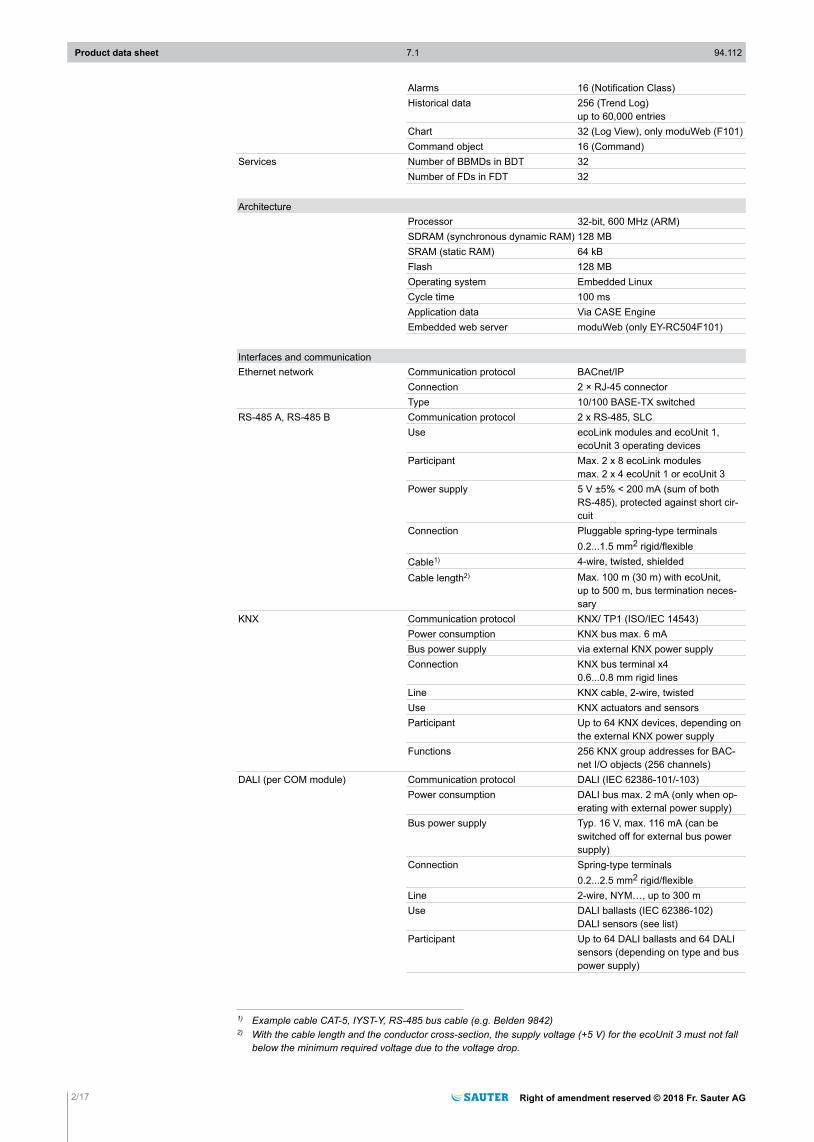
Alarms 16 (Notification Class)Historical data 256 (Trend Log)
up to 60,000 entriesChart 32 (Log View), only moduWeb (F101)Command object 16 (Command)
Services Number of BBMDs in BDT 32Number of FDs in FDT 32
ArchitectureProcessor 32-bit, 600 MHz (ARM)SDRAM (synchronous dynamic RAM) 128 MBSRAM (static RAM) 64 kBFlash 128 MBOperating system Embedded LinuxCycle time 100 msApplication data Via CASE EngineEmbedded web server moduWeb (only EY-RC504F101)
Interfaces and communicationEthernet network Communication protocol BACnet/IP
Connection 2 × RJ-45 connectorType 10/100 BASE-TX switched
RS-485 A, RS-485 B Communication protocol 2 x RS-485, SLCUse ecoLink modules and ecoUnit 1,
ecoUnit 3 operating devicesParticipant Max. 2 x 8 ecoLink modules
max. 2 x 4 ecoUnit 1 or ecoUnit 3Power supply 5 V ±5% < 200 mA (sum of both
RS-485), protected against short cir-cuit
Connection Pluggable spring-type terminals0.2...1.5 mm2 rigid/flexible
Cable1) 4-wire, twisted, shieldedCable length2) Max. 100 m (30 m) with ecoUnit,
up to 500 m, bus termination neces-sary
KNX Communication protocol KNX/ TP1 (ISO/IEC 14543)Power consumption KNX bus max. 6 mABus power supply via external KNX power supplyConnection KNX bus terminal x4
0.6...0.8 mm rigid linesLine KNX cable, 2-wire, twistedUse KNX actuators and sensorsParticipant Up to 64 KNX devices, depending on
the external KNX power supplyFunctions 256 KNX group addresses for BAC-
net I/O objects (256 channels)DALI (per COM module) Communication protocol DALI (IEC 62386-101/-103)
Power consumption DALI bus max. 2 mA (only when op-erating with external power supply)
Bus power supply Typ. 16 V, max. 116 mA (can beswitched off for external bus powersupply)
Connection Spring-type terminals0.2...2.5 mm2 rigid/flexible
Line 2-wire, NYM…, up to 300 mUse DALI ballasts (IEC 62386-102)
DALI sensors (see list)Participant Up to 64 DALI ballasts and 64 DALI
sensors (depending on type and buspower supply)
1) Example cable CAT-5, IYST-Y, RS-485 bus cable (e.g. Belden 9842)2) With the cable length and the conductor cross-section, the supply voltage (+5 V) for the ecoUnit 3 must not fall
below the minimum required voltage due to the voltage drop.
Product data sheet 7.1 94.112
2/17 Right of amendment reserved © 2018 Fr. Sauter AG
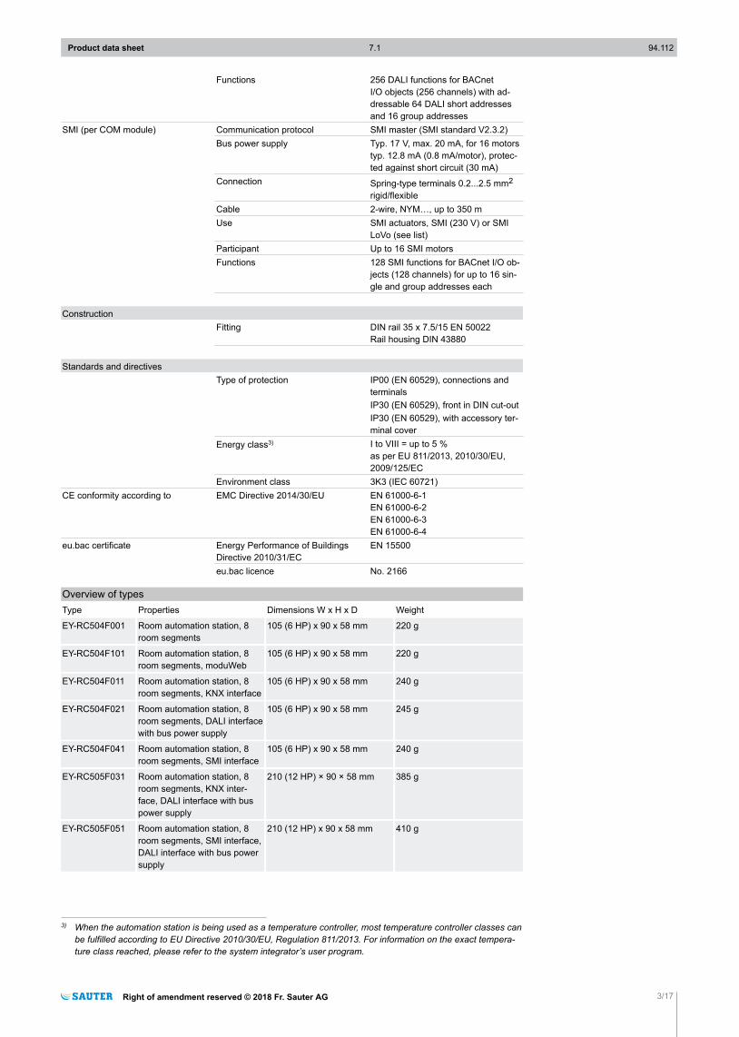
Functions 256 DALI functions for BACnetI/O objects (256 channels) with ad-dressable 64 DALI short addressesand 16 group addresses
SMI (per COM module) Communication protocol SMI master (SMI standard V2.3.2)Bus power supply Typ. 17 V, max. 20 mA, for 16 motors
typ. 12.8 mA (0.8 mA/motor), protec-ted against short circuit (30 mA)
Connection Spring-type terminals 0.2...2.5 mm2
rigid/flexibleCable 2-wire, NYM…, up to 350 mUse SMI actuators, SMI (230 V) or SMI
LoVo (see list)Participant Up to 16 SMI motorsFunctions 128 SMI functions for BACnet I/O ob-
jects (128 channels) for up to 16 sin-gle and group addresses each
ConstructionFitting DIN rail 35 x 7.5/15 EN 50022
Rail housing DIN 43880
Standards and directivesType of protection IP00 (EN 60529), connections and
terminalsIP30 (EN 60529), front in DIN cut-outIP30 (EN 60529), with accessory ter-minal cover
Energy class3) I to VIII = up to 5 %as per EU 811/2013, 2010/30/EU,2009/125/EC
Environment class 3K3 (IEC 60721)CE conformity according to EMC Directive 2014/30/EU EN 61000-6-1
EN 61000-6-2EN 61000-6-3EN 61000-6-4
eu.bac certificate Energy Performance of BuildingsDirective 2010/31/EC
EN 15500
eu.bac licence No. 2166
Overview of typesType Properties Dimensions W x H x D Weight
EY-RC504F001 Room automation station, 8room segments
105 (6 HP) x 90 x 58 mm 220 g
EY-RC504F101 Room automation station, 8room segments, moduWeb
105 (6 HP) x 90 x 58 mm 220 g
EY-RC504F011 Room automation station, 8room segments, KNX interface
105 (6 HP) x 90 x 58 mm 240 g
EY-RC504F021 Room automation station, 8room segments, DALI interfacewith bus power supply
105 (6 HP) x 90 x 58 mm 245 g
EY-RC504F041 Room automation station, 8room segments, SMI interface
105 (6 HP) x 90 x 58 mm 240 g
EY-RC505F031 Room automation station, 8room segments, KNX inter-face, DALI interface with buspower supply
210 (12 HP) × 90 × 58 mm 385 g
EY-RC505F051 Room automation station, 8room segments, SMI interface,DALI interface with bus powersupply
210 (12 HP) x 90 x 58 mm 410 g
3) When the automation station is being used as a temperature controller, most temperature controller classes canbe fulfilled according to EU Directive 2010/30/EU, Regulation 811/2013. For information on the exact tempera-ture class reached, please refer to the system integrator’s user program.
Product data sheet 7.1 94.112
Right of amendment reserved © 2018 Fr. Sauter AG 3/17
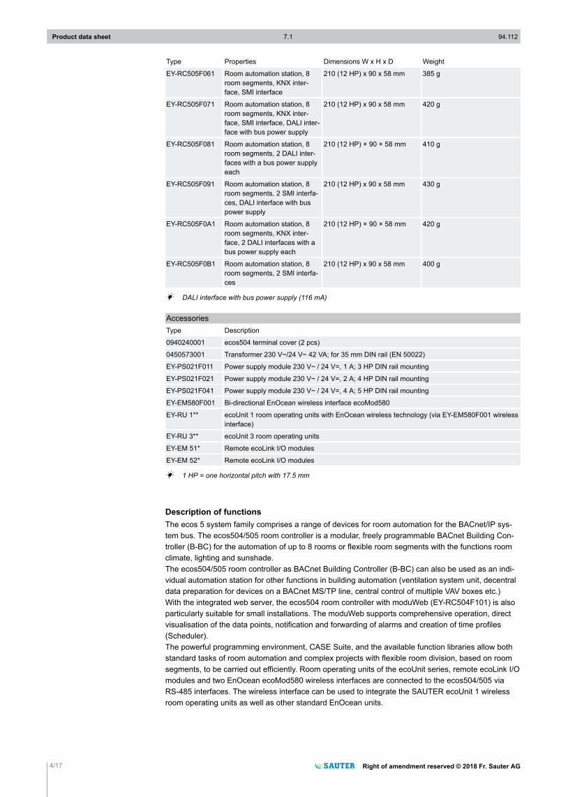
Type Properties Dimensions W x H x D Weight
EY-RC505F061 Room automation station, 8room segments, KNX inter-face, SMI interface
210 (12 HP) x 90 x 58 mm 385 g
EY-RC505F071 Room automation station, 8room segments, KNX inter-face, SMI interface, DALI inter-face with bus power supply
210 (12 HP) x 90 x 58 mm 420 g
EY-RC505F081 Room automation station, 8room segments, 2 DALI inter-faces with a bus power supplyeach
210 (12 HP) × 90 × 58 mm 410 g
EY-RC505F091 Room automation station, 8room segments, 2 SMI interfa-ces, DALI interface with buspower supply
210 (12 HP) x 90 x 58 mm 430 g
EY-RC505F0A1 Room automation station, 8room segments, KNX inter-face, 2 DALI interfaces with abus power supply each
210 (12 HP) × 90 × 58 mm 420 g
EY-RC505F0B1 Room automation station, 8room segments, 2 SMI interfa-ces
210 (12 HP) x 90 x 58 mm 400 g
A DALI interface with bus power supply (116 mA)
AccessoriesType Description
0940240001 ecos504 terminal cover (2 pcs)
0450573001 Transformer 230 V~/24 V~ 42 VA; for 35 mm DIN rail (EN 50022)
EY-PS021F011 Power supply module 230 V~ / 24 V=, 1 A; 3 HP DIN rail mounting
EY-PS021F021 Power supply module 230 V~ / 24 V=, 2 A; 4 HP DIN rail mounting
EY-PS021F041 Power supply module 230 V~ / 24 V=, 4 A; 5 HP DIN rail mounting
EY-EM580F001 Bi-directional EnOcean wireless interface ecoMod580
EY-RU 1** ecoUnit 1 room operating units with EnOcean wireless technology (via EY-EM580F001 wirelessinterface)
EY-RU 3** ecoUnit 3 room operating units
EY-EM 51* Remote ecoLink I/O modules
EY-EM 52* Remote ecoLink I/O modules
A 1 HP = one horizontal pitch with 17.5 mm
Description of functionsThe ecos 5 system family comprises a range of devices for room automation for the BACnet/IP sys-tem bus. The ecos504/505 room controller is a modular, freely programmable BACnet Building Con-troller (B-BC) for the automation of up to 8 rooms or flexible room segments with the functions roomclimate, lighting and sunshade.The ecos504/505 room controller as BACnet Building Controller (B-BC) can also be used as an indi-vidual automation station for other functions in building automation (ventilation system unit, decentraldata preparation for devices on a BACnet MS/TP line, central control of multiple VAV boxes etc.)With the integrated web server, the ecos504 room controller with moduWeb (EY-RC504F101) is alsoparticularly suitable for small installations. The moduWeb supports comprehensive operation, directvisualisation of the data points, notification and forwarding of alarms and creation of time profiles(Scheduler).The powerful programming environment, CASE Suite, and the available function libraries allow bothstandard tasks of room automation and complex projects with flexible room division, based on roomsegments, to be carried out efficiently. Room operating units of the ecoUnit series, remote ecoLink I/Omodules and two EnOcean ecoMod580 wireless interfaces are connected to the ecos504/505 viaRS-485 interfaces. The wireless interface can be used to integrate the SAUTER ecoUnit 1 wirelessroom operating units as well as other standard EnOcean units.
Product data sheet 7.1 94.112
4/17 Right of amendment reserved © 2018 Fr. Sauter AG
A KNX interface (variants F011, F031, F061, F071, F0A1) allows the use of individual KNX compo-nents in the room, such as operating devices, actuators or sensors, in order to cover special require-ments.A DALI interface with integrated DALI bus power supply (variants F021, F031, F051, F071, F091) en-ables the direct connection of DALI electronic ballasts (EB) and DALI sensors for integrated lightingcontrol or regulation.The variants with two DALI interfaces (F081, F0A1) can be operated individually as DALI bus 1 andDALI bus 2, each with a DALI bus power supply of max. 116 mA, or connected in parallel as a DALIbus with a DALI bus power supply of max. 232 mA.One or two SMI interfaces (1x: F041, F051, F061, F071; 2x: F091, F0B1) each enable the activationof up to 16 SMI actuators (SMI (230 V) or SMI LoVo; a mix of SMI (230 V) and SMI LoVo on the samebus is not permitted) for simple, intelligent, precise sunshading functions for window blinds, rollershutters etc.
)NOTEAll information related to the operation of the web server is contained in the document “modu525 weboperation” (manual 7010050001). More detailed information on BACnet functionality of the station can befound in the PICS documentation.
Intended useThis product is only suitable for the purpose intended by the manufacturer, as described in the “De-scription of operation” section.All related product regulations must also be adhered to. Changing or converting the product is not ad-missible.
Engineering notesThe ecos504/505 is a modular device suitable for series installation (DIN 43880) on 35 mm DIN rails.The installation position can be chosen at will.
Fitting and installation
)NOTEWhen fitted in an installation box or cabinet, it must be ensured that there is sufficient ventilation to allowthe permissible operating temperature to be maintained.
The following conditions must be met or observed during the installation:• Connection may only be performed when the system is disconnected from the electrical supply.• The unit must be protected against contact.• There must be an external primary isolating facility.• There must be a connection of the protective earth to the relevant terminal.• The connection to terminal MM may not be interrupted by switching elements.
Special standards such as IEC/EN 61508, IEC/EN 61511, IEC/EN 61131-1 and -2, and other similarones, were not taken into account. Local requirements regarding installation, usage, access, accessrights, accident prevention, safety, dismantling and disposal must be taken into account. Furthermore,the installation standards EN 50178, 50310, 50110, 50274, 61140 and similar must be observed.The communication wiring (Ethernet, RS-485, KNX) must be separated from current-carrying and liveinstallations.The communication wiring (DALI, SMI) can be routed with current-carrying and live installations (typi-cally with electrical installation wire NYM 5x …).
!DANGERElectric shock!►The SMI and DALI buses are not SELV electrical circuits. The DALI and SMI bus cabling must be trea-
ted as 230 V.►A mix of the two operating modes (230 V and LoVo) on one SMI bus is not permitted.
For further safety instructions, information and guidelines, see fitting instructions P100002325.
Installation in small distribution boxesThe ecos504/505 is suitable for fitting in standard small distribution boxes using DIN rail housing. Thesmall distribution boxes are available in variants for surface mounting and flush mounting from vari-
Product data sheet 7.1 94.112
Right of amendment reserved © 2018 Fr. Sauter AG 5/17
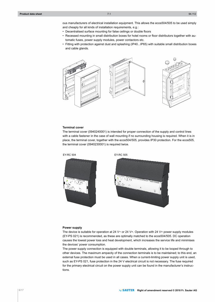
ous manufacturers of electrical installation equipment. This allows the ecos504/505 to be used simplyand cheaply for all kinds of installation requirements, e.g.:• Decentralised surface mounting for false ceilings or double floors• Recessed mounting in small distribution boxes for hotel rooms or floor distributors together with au-
tomatic fuses, power supply modules, power contactors etc.• Fitting with protection against dust and splashing (IP40...IP65) with suitable small distribution boxes
and cable glands.
Vo l
PI at
30 A
C 4
0 0 V/6
3 AV
DE
PG21/29
PG21/29
PG16/21
PG16/21
PG16/21
PG16/21
PG16
PG16
PG16
PG16
PG16
PG16
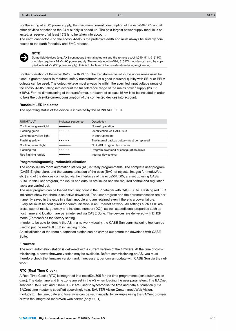
Terminal coverThe terminal cover (0940240001) is intended for proper connection of the supply and control lineswith a cable fastener in the case of wall mounting if no surrounding housing is required. When it is inplace, the terminal cover, together with the ecos504/505, provides IP30 protection. For the ecos505,the terminal cover (0940230001) is required twice.
EY-RC 504 EY-RC 505
Power supplyThe device is suitable for operation at 24 V~ or 24 V=. Operation with 24 V= power supply modules(EY-PS 021) is recommended, as these are optimally matched to the ecos504/505. DC operationcauses the lowest power loss and heat development, which increases the service life and minimisesthe devices’ power consumption.The power supply connection is equipped with double terminals, allowing it to be looped through toother devices. The maximum ampacity of the connection terminals is to be maintained; to this end, anexternal fuse protection must be used in all cases. When a current-limiting power supply unit is used,such as EY-PS 021, fuse protection in the 24 V electrical circuit is not necessary. The fuse requiredfor the primary electrical circuit on the power supply unit can be found in the manufacturer’s instruc-tions.
Product data sheet 7.1 94.112
6/17 Right of amendment reserved © 2018 Fr. Sauter AG
For the sizing of a DC power supply, the maximum current consumption of the ecos504/505 and allother devices attached to the 24 V supply is added up. The next-largest power supply module is se-lected; a reserve of at least 15% is to be taken into account.The earth connector on the ecos504/505 is the protective earth and must always be suitably con-nected to the earth for safety and EMC reasons.
)NOTESome field devices (e.g. AXS continuous thermal actuator) and the remote ecoLink510, 511, 512* I/Omodules require a 24 V~ AC power supply. The remote ecoLink514, 515 I/O modules can also be sup-plied with 24 V= (DC power supply). This is to be taken into consideration during engineering.
For the operation of the ecos504/505 with 24 V~, the transformer listed in the accessories must beused. If greater power is required, safety transformers of a good industrial quality with SELV or PELVoutputs can be used. The output voltage must always lie within the specified input voltage range ofthe ecos504/505, taking into account the full tolerance range of the mains power supply (230 V±10%). For the dimensioning of the transformer, a reserve of at least 15 VA is to be included in orderto take the pulse-like current consumption of the connected devices into account.
Run/fault LED indicatorThe operating status of the device is indicated by the RUN/FAULT LED.
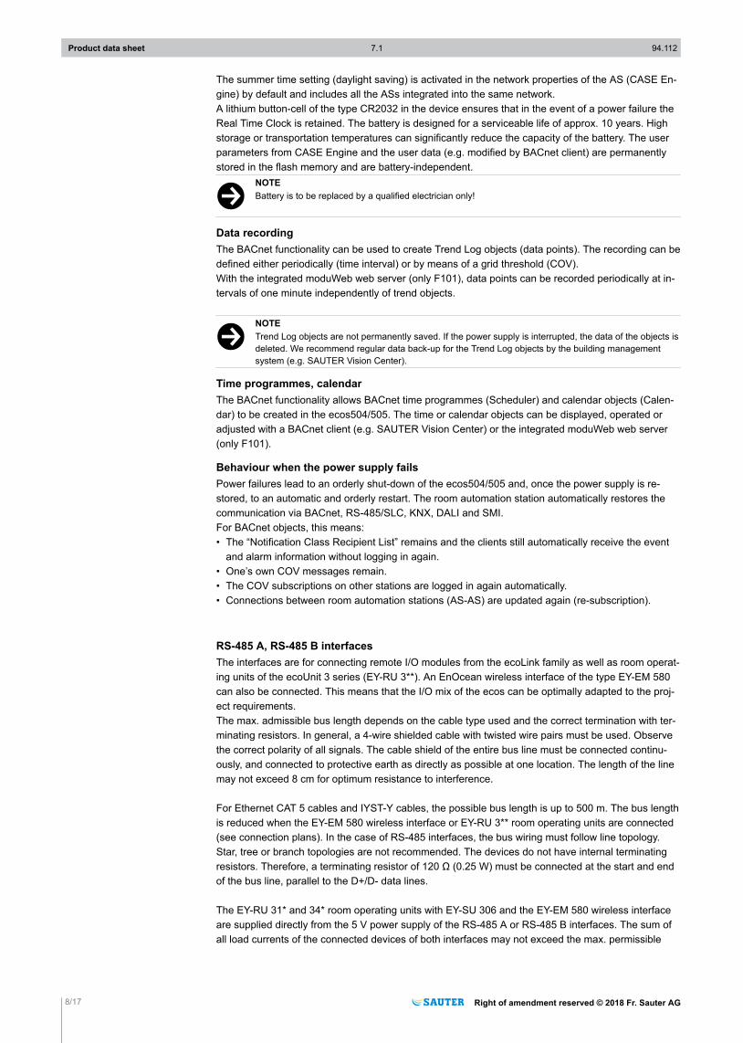
RUN/FAULT Indicator sequence DescriptionContinuous green light ------------ Normal operationFlashing green • • • • • • Identification via CASE SunContinuous yellow light ------------ In start-up modeFlashing yellow • • • • • • The internal backup battery must be replacedContinuous red light ------------ No CASE Engine plan in ecosFlashing red • • • • • • Program download or configuration activeRed flashing rapidly ••••••••••• Internal device error
Programming/configuration/initialisationThe ecos504/505 room automation station (AS) is freely programmable. The complete user program(CASE Engine plan), and the parameterisation of the ecos (BACnet objects, images for moduWeb,etc.) and of the devices connected via the interfaces of the ecos504/505, are set up using CASESuite. In this user program, the inputs and outputs are linked and the required control and regulationtasks are carried out.The user program can be loaded from any point in the IP network with CASE Suite. Flashing red LEDindicators show that there is an active download. The user program and the parameterisation are per-manently saved in the ecos in a flash module and are retained even if there is a power failure.Every AS must be configured for communication in an Ethernet network. All settings such as IP ad-dress, subnet mask, gateway and instance number (DOI), as well as additional properties such ashost name and location, are parameterised via CASE Suite. The devices are delivered with DHCPmode (Zeroconf) as the factory setting.In order to be able to identify the AS in a network visually, the CASE Sun commissioning tool can beused to put the run/fault LED in flashing mode.An initialisation of the room automation station can be carried out before the download with CASESuite.
FirmwareThe room automation station is delivered with a current version of the firmware. At the time of com-missioning, a newer firmware version may be available. Before commissioning an AS, you musttherefore check the firmware version and, if necessary, perform an update with CASE Sun via the net-work.
RTC (Real Time Clock)A Real Time Clock (RTC) is integrated into ecos504/505 for the time programmes (schedulers/calen-dars). The date, time and time zone are set in the AS when loading the user parameters. The BACnetservices “DM-TS-B” and “DM-UTC-B” are used to synchronise the time and date automatically if aBACnet time master is specified accordingly (e.g. SAUTER Vision Center, moduWeb Vision,modu525). The time, date and time zone can be set manually, for example using the BACnet browseror with the integrated moduWeb web server (only F101).
Product data sheet 7.1 94.112
Right of amendment reserved © 2018 Fr. Sauter AG 7/17
The summer time setting (daylight saving) is activated in the network properties of the AS (CASE En-gine) by default and includes all the ASs integrated into the same network.A lithium button-cell of the type CR2032 in the device ensures that in the event of a power failure theReal Time Clock is retained. The battery is designed for a serviceable life of approx. 10 years. Highstorage or transportation temperatures can significantly reduce the capacity of the battery. The userparameters from CASE Engine and the user data (e.g. modified by BACnet client) are permanentlystored in the flash memory and are battery-independent.
)NOTEBattery is to be replaced by a qualified electrician only!
Data recordingThe BACnet functionality can be used to create Trend Log objects (data points). The recording can bedefined either periodically (time interval) or by means of a grid threshold (COV).With the integrated moduWeb web server (only F101), data points can be recorded periodically at in-tervals of one minute independently of trend objects.
)NOTETrend Log objects are not permanently saved. If the power supply is interrupted, the data of the objects isdeleted. We recommend regular data back-up for the Trend Log objects by the building managementsystem (e.g. SAUTER Vision Center).
Time programmes, calendarThe BACnet functionality allows BACnet time programmes (Scheduler) and calendar objects (Calen-dar) to be created in the ecos504/505. The time or calendar objects can be displayed, operated oradjusted with a BACnet client (e.g. SAUTER Vision Center) or the integrated moduWeb web server(only F101).
Behaviour when the power supply failsPower failures lead to an orderly shut-down of the ecos504/505 and, once the power supply is re-stored, to an automatic and orderly restart. The room automation station automatically restores thecommunication via BACnet, RS-485/SLC, KNX, DALI and SMI.For BACnet objects, this means:• The “Notification Class Recipient List” remains and the clients still automatically receive the event
and alarm information without logging in again.• One’s own COV messages remain.• The COV subscriptions on other stations are logged in again automatically.• Connections between room automation stations (AS-AS) are updated again (re-subscription).
RS-485 A, RS-485 B interfacesThe interfaces are for connecting remote I/O modules from the ecoLink family as well as room operat-ing units of the ecoUnit 3 series (EY-RU 3**). An EnOcean wireless interface of the type EY-EM 580can also be connected. This means that the I/O mix of the ecos can be optimally adapted to the proj-ect requirements.The max. admissible bus length depends on the cable type used and the correct termination with ter-minating resistors. In general, a 4-wire shielded cable with twisted wire pairs must be used. Observethe correct polarity of all signals. The cable shield of the entire bus line must be connected continu-ously, and connected to protective earth as directly as possible at one location. The length of the linemay not exceed 8 cm for optimum resistance to interference.
For Ethernet CAT 5 cables and IYST-Y cables, the possible bus length is up to 500 m. The bus lengthis reduced when the EY-EM 580 wireless interface or EY-RU 3** room operating units are connected(see connection plans). In the case of RS-485 interfaces, the bus wiring must follow line topology.Star, tree or branch topologies are not recommended. The devices do not have internal terminatingresistors. Therefore, a terminating resistor of 120 Ω (0.25 W) must be connected at the start and endof the bus line, parallel to the D+/D- data lines.
The EY-RU 31* and 34* room operating units with EY-SU 306 and the EY-EM 580 wireless interfaceare supplied directly from the 5 V power supply of the RS-485 A or RS-485 B interfaces. The sum ofall load currents of the connected devices of both interfaces may not exceed the max. permissible
Product data sheet 7.1 94.112
8/17 Right of amendment reserved © 2018 Fr. Sauter AG
current of 200 mA. Furthermore, it must be ensured that there is a sufficient cable cross-section (=0.5mm2) to limit the voltage drop across the power cable to max. 1.2 V.
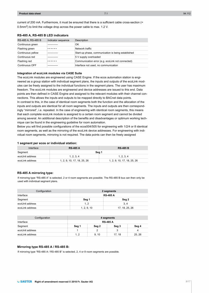
RS-485 A, RS-485 B LED indicatorsRS-485 A, RS-485 B Indicator sequence DescriptionContinuous green ------------ OKFlashing green • • • • • • Network trafficContinuous yellow ------------ Start-up phase, communication is being establishedContinuous red ------------ 5 V supply overloadedFlashing red • • • • • • Communication error (e.g. ecoLink not connected)Continuous OFF ------------ Interface not used, no communication
Integration of ecoLink modules via CASE SuiteThe ecoLink modules are engineered using CASE Engine. If the ecos automation station is engi-neered as a group station with individual segment plans, the inputs and outputs of the ecoLink mod-ules can be freely assigned to the individual functions in the segment plans. The user has maximumfreedom. The ecoLink modules are engineered and device addresses are issued to this end. Datapoints are then defined in CASE Engine and assigned to the relevant modules with their channel con-nections. This allows the inputs and outputs to be mapped directly to BACnet data points.In contrast to this, in the case of identical room segments both the function and the allocation of theinputs and outputs are identical for all room segments. The inputs and outputs are then correspond-ingly “mirrored”, i.e. repeated. In the case of engineering with identical room segments, this meansthat each complete ecoLink module is assigned to a certain room segment and cannot be dividedamong several. An additional description of the benefits and disadvantages or optimum working tech-nique can be found in the engineering guideline for room automation.Below you will find possible configurations of the ecos504/505 for engineering with 1/2/4 or 8 identicalroom segments, as well as the mirroring of the ecoLink device addresses. For engineering with indi-vidual room segments, mirroring is not required. The data points can then be freely assigned
1 segment per ecos or individual station:Interface RS-485 A RS-485 B
Segment Seg 1ecoUnit address 1, 2, 3, 4 1, 2, 3, 4ecoLink address 1, 2, 9, 10, 17, 18, 25, 26 1, 2, 9, 10, 17, 18, 25, 26
RS-485 A mirroring type:If mirroring type “RS-485 A” is selected, 2 or 4 room segments are possible. The RS-485 B bus can then only beused with individual segment plans.
Configuration 2 segmentsInterface RS-485 ASegment Seg 1 Seg 2ecoUnit address 1, 2 3, 4ecoLink address 1, 2, 9, 10 17, 18, 25, 26
Configuration 4 segmentsInterface RS-485 ASegment Seg 1 Seg 2 Seg 3 Seg 4ecoUnit address 1 2 3 4ecoLink address 1, 2 9, 10 17, 18 25, 26
Mirroring type RS-485 A / RS-485 B:If mirroring type “RS-485 A / RS-485 B” is selected, 2, 4 or 8 room segments are possible.
Product data sheet 7.1 94.112
Right of amendment reserved © 2018 Fr. Sauter AG 9/17

Configuration 2 segmentsInterface RS-485 A RS-485 BSegment Seg 1 Seg 2ecoUnit address 1, 2, 3, 4 1, 2, 3, 4ecoLink address 1, 2, 9, 10, 17, 18, 25, 26 1, 2, 9, 10, 17, 18, 25, 26
Configuration 4 segmentsInterface RS-485 A RS-485 BSegment Seg 1 Seg 2 Seg 3 Seg 4ecoUnit address 1, 2 3, 4 1, 2 3, 4ecoLink address 1, 2, 9, 10 17, 18, 25, 26 1, 2, 9, 10 17, 18, 25, 26
Configuration 8 segmentsInterface RS-485 A RS-485 BSegment Seg 1 Seg 2 Seg 3 Seg 4 Seg 5 Seg 6 Seg 7 Seg 8ecoUnit address 1 2 3 4 1 2 3 4ecoLink address 1, 2 9, 10 17, 18 25, 26 1, 2 9, 10 17, 18 25, 26
Start-up behaviour/monitoring functionThe communication between ecos and the engineered ecoLink modules at the RS-485 buses ismonitored. If the communication fails for more than the monitoring time of 10 s, the affected ecoLinkmodules switch to the safety status. The data points in the ecos are marked with the status “unrelia-ble”. All outputs of the affected ecoLink modules are switched to the defined value for the safety state(“relinquish default”).Equally, engineered room operating units are monitored; the status of the devices is shown by meansof corresponding “valid” outputs on the ROOM_UNIT block in CASE Engine.Details on start-up behaviour and monitoring functions can be found in the documentation of the pe-ripheral devices in question.
KNX interfaceThe KNX interface enables direct integration of KNX devices into BACnet/IP automation at room lev-el. The KNX devices (e.g. operating devices, actuators or sensors) are engineered in CASE Engine.The KNX data points are mapped to the CASE Engine input or output objects. This allows KNX datapoints to be used in the free programming of regulation and logic functions with CASE Engine, likeany other input or output objects. Here all KNX devices communicate with the ecos. Using the func-tion for individual segment plans in CASE Engine, KNX data points can also be integrated into theconcept of flexible room division with room segments and AS groups.For commissioning, the engineered KNX data points are exported from CASE Engine with the deter-mined group addresses and are imported into the ETS KNX configuration tool. A three-level groupaddress structure is a prerequisite for this. With ETS, the KNX devices are then selected from the da-tabase and the existing data point objects are assigned to the imported list of group addresses. Fur-thermore, ETS can be used to configure and parameterise the KNX devices.Connecting KNX devices to one another using ETS is not necessary and would be disadvantageousas all logic connections and regulation functions are contained in the CASE Engine program for a bet-ter overview and greater flexibility.The KNX network is thus a local field bus within the rooms or room segments that are regulated by anecos504/505. KNX line and area couplers may no longer be necessary with this BACnet topology.This means that many KNX bus segments can exist in a building. For simple commissioning andmaintenance, access can be made directly to all KNX segments from the shared BACnet/IP (Ether-net). The work station with CASE Engine and the ETS KNX configuration tool is connected with theEthernet network; the KNX communication is then tunnelled through the Ethernet and ecos504/505 tothe selected local KNX network.This means that it is not necessary to be connected locally to every individual KNX segment. Fromecos504/505 firmware V2.8.3 and KNX firmware V1.1.4 upwards, the KNX tunnelling functionality forETS is supported directly on the ecos504/505, which means that no external KNX interface is re-quired for the commissioning of KNX devices.In addition to the ecos504/505 and the KNX field devices, a KNX power supply module is needed, asshown in the connection diagram.All KNX devices can be used with the ecos KNX. However, the following must be considered:• Supported KNX data point type (DPT) – see table
Product data sheet 7.1 94.112
10/17 Right of amendment reserved © 2018 Fr. Sauter AG
• Design of the external KNX bus power supply• Number of KNX group addresses to be used with the corresponding external KNX group communi-
cation objects
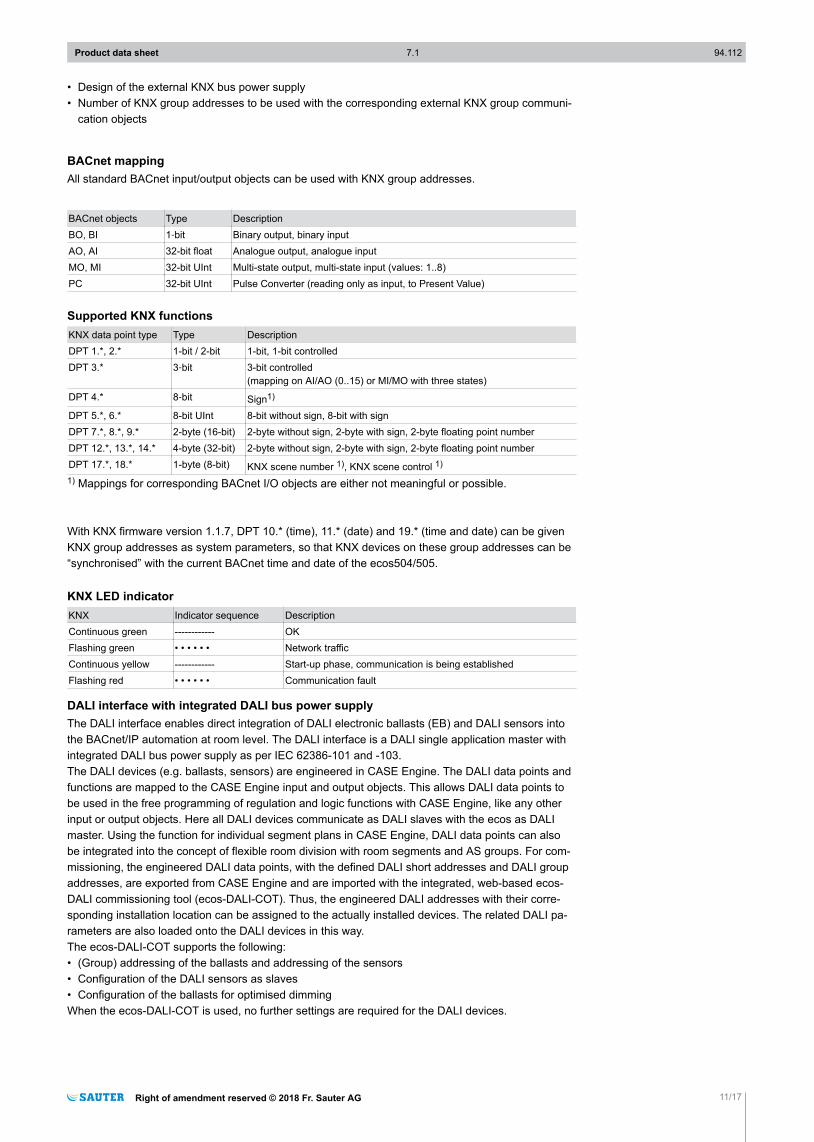
BACnet mappingAll standard BACnet input/output objects can be used with KNX group addresses.
BACnet objects Type DescriptionBO, BI 1‑bit Binary output, binary inputAO, AI 32-bit float Analogue output, analogue inputMO, MI 32-bit UInt Multi-state output, multi-state input (values: 1..8)PC 32-bit UInt Pulse Converter (reading only as input, to Present Value)
Supported KNX functionsKNX data point type Type DescriptionDPT 1.*, 2.* 1-bit / 2-bit 1-bit, 1-bit controlledDPT 3.* 3‑bit 3-bit controlled
(mapping on AI/AO (0..15) or MI/MO with three states)DPT 4.* 8‑bit Sign1)
DPT 5.*, 6.* 8-bit UInt 8-bit without sign, 8-bit with signDPT 7.*, 8.*, 9.* 2-byte (16-bit) 2-byte without sign, 2-byte with sign, 2-byte floating point numberDPT 12.*, 13.*, 14.* 4-byte (32-bit) 2-byte without sign, 2-byte with sign, 2-byte floating point numberDPT 17.*, 18.* 1-byte (8-bit) KNX scene number 1), KNX scene control 1)
1) Mappings for corresponding BACnet I/O objects are either not meaningful or possible.
With KNX firmware version 1.1.7, DPT 10.* (time), 11.* (date) and 19.* (time and date) can be givenKNX group addresses as system parameters, so that KNX devices on these group addresses can be“synchronised” with the current BACnet time and date of the ecos504/505.
KNX LED indicatorKNX Indicator sequence DescriptionContinuous green ------------ OKFlashing green • • • • • • Network trafficContinuous yellow ------------ Start-up phase, communication is being establishedFlashing red • • • • • • Communication fault
DALI interface with integrated DALI bus power supplyThe DALI interface enables direct integration of DALI electronic ballasts (EB) and DALI sensors intothe BACnet/IP automation at room level. The DALI interface is a DALI single application master withintegrated DALI bus power supply as per IEC 62386-101 and -103.The DALI devices (e.g. ballasts, sensors) are engineered in CASE Engine. The DALI data points andfunctions are mapped to the CASE Engine input and output objects. This allows DALI data points tobe used in the free programming of regulation and logic functions with CASE Engine, like any otherinput or output objects. Here all DALI devices communicate as DALI slaves with the ecos as DALImaster. Using the function for individual segment plans in CASE Engine, DALI data points can alsobe integrated into the concept of flexible room division with room segments and AS groups. For com-missioning, the engineered DALI data points, with the defined DALI short addresses and DALI groupaddresses, are exported from CASE Engine and are imported with the integrated, web-based ecos-DALI commissioning tool (ecos-DALI-COT). Thus, the engineered DALI addresses with their corre-sponding installation location can be assigned to the actually installed devices. The related DALI pa-rameters are also loaded onto the DALI devices in this way.The ecos-DALI-COT supports the following:• (Group) addressing of the ballasts and addressing of the sensors• Configuration of the DALI sensors as slaves• Configuration of the ballasts for optimised dimmingWhen the ecos-DALI-COT is used, no further settings are required for the DALI devices.
Product data sheet 7.1 94.112
Right of amendment reserved © 2018 Fr. Sauter AG 11/17
Connecting DALI devices directly to each other (sensor to ballast) is not necessary and would be dis-advantageous as all logic connections and regulation functions are contained in the CASE Engineprogram for a better overview and greater flexibility.The DALI network is thus a local field bus for the lighting within the rooms or room segments that areregulated by an ecos504/505. This means that many DALI bus segments can exist in a building. Forsimple commissioning and maintenance, access can be made directly to all DALI segments from theshared BACnet/IP (Ethernet). The work station with CASE Engine and a web browser for the ecos-DALI-COT is connected with the Ethernet network and the corresponding IP address of theecos504/505. This means that it is not necessary to be connected locally to every individual DALIsegment.The ecos504/505 with the DALI module has an integrated DALI bus power supply (up to 116 mA). Asshown in the connection diagram, individual usage of the DALI modules (each up to 116 mA, each 1x64 ballasts, 1x 64 sensors) or the parallel connection of 2 DALI modules (up to 232 mA, each 64 bal-lasts and each 64 sensors) is possible. When the 2 DALI modules are connected in parallel for in-creased bus power supply, only 1x 64 DALI ballasts and up to 1x 64 sensors can be used. In thiscase, the 2nd interface only serves as the DALI bus power supply. The internal DALI bus power sup-ply can also be switched off via CASE or ecos-DALI-COT in order to use an external DALI power sup-ply module. Note that all power supplies connected to the bus must not supply a combined total ofmore than 250 mA. The internal DALI bus power supply has short-circuit monitoring as per IEC62386-101 (section 6.6.2). Therefore, when operating simultaneously with an internal and an externalpower supply, the external power supply must not have short-circuit switch-off.All DALI ballast devices according to IEC 62386-102 can be used with the ecos DALI. The followingmust be considered:• Supported DALI functions (see table)• No support for DALI ballast additional functions as per IEC 62386-2xx• Design of the DALI bus power supply• Number of DALI addresses and functions to be used• Consideration of the bus bandwidth via optimum settings for the DALI master functions (query inter-
vals, priority...)
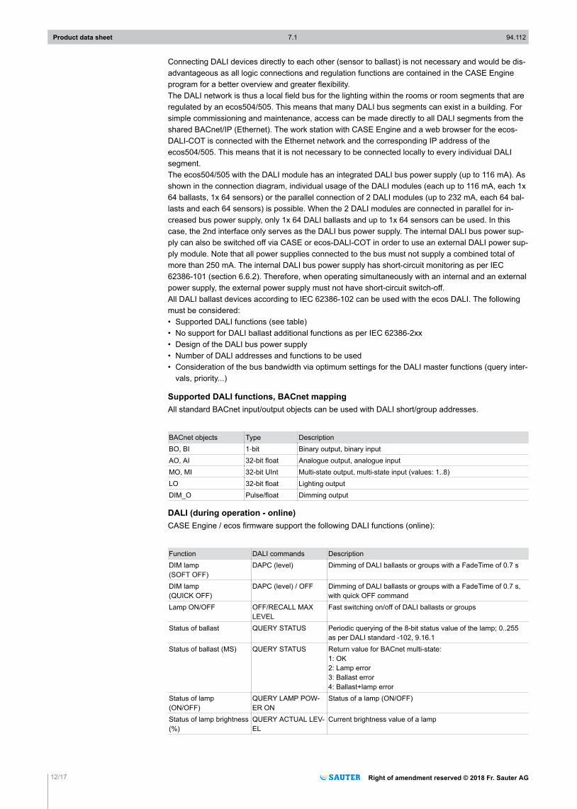
Supported DALI functions, BACnet mappingAll standard BACnet input/output objects can be used with DALI short/group addresses.
BACnet objects Type DescriptionBO, BI 1‑bit Binary output, binary inputAO, AI 32-bit float Analogue output, analogue inputMO, MI 32-bit UInt Multi-state output, multi-state input (values: 1..8)LO 32-bit float Lighting outputDIM_O Pulse/float Dimming output
DALI (during operation - online)CASE Engine / ecos firmware support the following DALI functions (online):
Function DALI commands DescriptionDIM lamp(SOFT OFF)
DAPC (level) Dimming of DALI ballasts or groups with a FadeTime of 0.7 s
DIM lamp (QUICK OFF)
DAPC (level) / OFF Dimming of DALI ballasts or groups with a FadeTime of 0.7 s,with quick OFF command
Lamp ON/OFF OFF/RECALL MAXLEVEL
Fast switching on/off of DALI ballasts or groups
Status of ballast QUERY STATUS Periodic querying of the 8-bit status value of the lamp; 0..255as per DALI standard -102, 9.16.1
Status of ballast (MS) QUERY STATUS Return value for BACnet multi-state:1: OK 2: Lamp error 3: Ballast error 4: Ballast+lamp error
Status of lamp (ON/OFF)
QUERY LAMP POW-ER ON
Status of a lamp (ON/OFF)
Status of lamp brightness(%)
QUERY ACTUAL LEV-EL
Current brightness value of a lamp
Product data sheet 7.1 94.112
12/17 Right of amendment reserved © 2018 Fr. Sauter AG

DALI (configuration)The ecos-DALI commissioning tool (COT) supports various DALI functions (config). The most impor-tant ones:
Function DALI commands DescriptionSet DALI device address SET SHORT ADDRESS Short address assignment for all DALI devices in the DALI net-
workSearch for DALI devices QUERY RANDOM Search for all connected devicesAssign DALI groups ADD TO GROUP Assignment of the DALI groups as per CASE assignment tableIdentify DALI devices RECALL MAX LEVEL Flashing of individual lamps to identify a device
DALI LED indicatorDALI Indicator sequence DescriptionContinuous green ------------ OK (all data points OK, no bus traffic)Flashing green • • • • • • OK (active bus traffic)Continuous yellow ------------ Start-up phase, communication is being establishedFlashing red • • • • • • Communication error (at least one data point cannot set up correct commu-
nication with the DALI device)Continuous red ------------ DALI bus supply error (no supply - short circuit or 230 V~ on bus)
Tested DALI devicesManufacturer DALI device type/profile RemarksDALI ballast:VariousOSRAMTRIDONICHelvarVossloh-SchwabeLunatonePhilipsBAGTCI
IEC 62386-102 Tested ballast profiles1)
-201 : Fluorescent tubes (device type 0)-204 : Low-voltage halogen lamps (device type 3)-205 : Power supply controller for light bulbs (device type 4)-207 : LED modules (device type 6)
DALI sensors:ThebenHTS Planospot360 DALI Multi-sensor with up to 5 instancesLunatone CS IR Multi-sensor (without IR functionality)Loytec LDALI-MS1 Multi-sensorOSRAM DALI LS/PD LI Multi-sensor1) Only ballast functions as per IEC 62386-102 (“basic functions”) and no additional functions fromIEC 62386-2xx (“typical functions for ballast devices”) are supported by the ecos-DALI firmware V1.x.Further supported devices are listed in the ecos-DALI compatibility list (D100317613).
SMI interface as SMI activatorThe SMI interface of the ecos504/505 serves as an SMI activator for controlling SMI actuators. Theyenable the direct integration, configuration and activation of up to 16 SMI actuators connected to theSMI bus. The activation of the motors can be carried out with CASE Engine and the correspondingBACnet input and output objects and be combined with regulation and logic functions using the freeprogramming of CASE Engine. Groups can be formed in order to activate SMI actuators as a com-plete group. Using the function for individual segment plans in CASE Engine, individual SMI actuatorscan also be integrated into the concept of flexible room division with room segments and AS groups.
The “SMI-easyMonitor” (download from www.standard-motor-interface.com) is required for the com-missioning and addressing of the SMI actuators. The tool can use a virtual serial port to access theSMI bus directly via ecos504/505 (“tunnelling”) and perform the addressing of the SMI actuators. NoUSB-SMI converter is required. The configuration of the end stops of the individual hangings (windowblinds, roller shutters,…) must be carried out on site directly on the motors using the individual settingtools to be obtained from the respective manufacturer. The commissioning via SMI-easyMonitorshould be carried out first. The parallel operation of SMI-easyMonitor and the ecos program for acti-vating SMI motors is not supported. The adjustment of the position and angle of the hangings (e.g.window blinds/slats) can be carried out individually using CASE Engine Plan. All SMI actuators canbe used with ecos-SMI (see ecos-SMI compatibility list). ecos-SMI supports the following SMI func-tions:
Product data sheet 7.1 94.112
Right of amendment reserved © 2018 Fr. Sauter AG 13/17
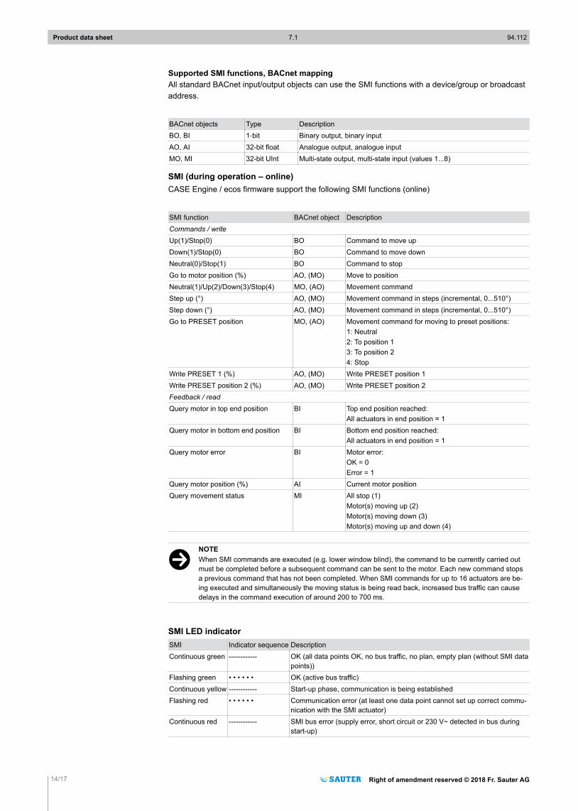
Supported SMI functions, BACnet mappingAll standard BACnet input/output objects can use the SMI functions with a device/group or broadcastaddress.
BACnet objects Type DescriptionBO, BI 1‑bit Binary output, binary inputAO, AI 32-bit float Analogue output, analogue inputMO, MI 32-bit UInt Multi-state output, multi-state input (values 1...8)
SMI (during operation – online)CASE Engine / ecos firmware support the following SMI functions (online)
SMI function BACnet object DescriptionCommands / writeUp(1)/Stop(0) BO Command to move upDown(1)/Stop(0) BO Command to move downNeutral(0)/Stop(1) BO Command to stopGo to motor position (%) AO, (MO) Move to positionNeutral(1)/Up(2)/Down(3)/Stop(4) MO, (AO) Movement commandStep up (°) AO, (MO) Movement command in steps (incremental, 0...510°)Step down (°) AO, (MO) Movement command in steps (incremental, 0...510°)Go to PRESET position MO, (AO) Movement command for moving to preset positions:
1: Neutral2: To position 13: To position 24: Stop
Write PRESET 1 (%) AO, (MO) Write PRESET position 1Write PRESET position 2 (%) AO, (MO) Write PRESET position 2Feedback / readQuery motor in top end position BI Top end position reached:
All actuators in end position = 1Query motor in bottom end position BI Bottom end position reached:
All actuators in end position = 1Query motor error BI Motor error:
OK = 0Error = 1
Query motor position (%) AI Current motor positionQuery movement status MI All stop (1)
Motor(s) moving up (2)Motor(s) moving down (3)Motor(s) moving up and down (4)
)NOTEWhen SMI commands are executed (e.g. lower window blind), the command to be currently carried outmust be completed before a subsequent command can be sent to the motor. Each new command stopsa previous command that has not been completed. When SMI commands for up to 16 actuators are be-ing executed and simultaneously the moving status is being read back, increased bus traffic can causedelays in the command execution of around 200 to 700 ms.
SMI LED indicatorSMI Indicator sequence DescriptionContinuous green ------------ OK (all data points OK, no bus traffic, no plan, empty plan (without SMI data
points))Flashing green • • • • • • OK (active bus traffic)Continuous yellow ------------ Start-up phase, communication is being establishedFlashing red • • • • • • Communication error (at least one data point cannot set up correct commu-
nication with the SMI actuator)Continuous red ------------ SMI bus error (supply error, short circuit or 230 V~ detected in bus during
start-up)
Product data sheet 7.1 94.112
14/17 Right of amendment reserved © 2018 Fr. Sauter AG

Tested SMI actuatorsManufacturer Device type RemarksDUNKER D370 SMI Window blind actuator 230 VELERO JA 05 Soft-SMI Window blind actuator 230 VGEIGER GJ5606k, E07 Window blind actuator 230 VFurther supported and tested devices are listed in the ecos-SMI compatibility list (D100370158).
Additional informationTechnical informationFitting instructions P100014308BACnet PICS ecos504/ecos505 D100275255BACnet BTL Certification No: BTL-30005 (V2.8.4b12) for EY-RC504F001AMEV attestation In preparationDeclaration on materials and the environment MD 94.112ecos 5 engineering guidelines See SAUTER extranetCompatibility list for ecos-EnOcean D100119337Compatibility list for ecos-DALI D100317613Compatibility list for ecos-SMI D100370158Operating manual for moduWeb 7010050001 (DE), 7010050002 (FR), 7010050003 (EN)
Applications as per eu.bac (eu.bac Cert)The ecos504/505 combined with ecoLink can be equipped with certified applications as single-roomcontrollers as per EN 15500 and the eu.bac “General Rules” and “Specific Rules”. The certificates areavailable at http://www.eubaccert.eu/licenses-by-criteria.asp. Further information on the applicationsfor the fan coil unit (2-/4-pipe, 2-pipe with reheater) and chilled/heated ceilings with very good controlresults (CA values between 0.0K and 0.3K) is available from SAUTER.
DisposalWhen disposing of the product, observe the currently applicable local laws.More information on materials can be found in the Declaration on materials and the environment forthis product.
Table of typesType COM1 COM2 COM3 Protection classEY-RC504F001 -- IEY-RC504F101 -- IEY-RC504F011 KNX IEY-RC504F021 DALI IEY-RC504F041 SMI IEY-RC505F031 KNX DALI -- IEY-RC505F051 SMI DALI -- IEY-RC505F061 KNX SMI -- IEY-RC595F071 KNX SMI DALI IEY-RC505F081 -- DALI1 DALI2 IEY-RC505F091 SMI1 SMI2 DALI IEY-RC505F0A1 KNX DALI1 DALI2 IEY-RC505F0B1 SMI1 SMI2 -- I
Product data sheet 7.1 94.112
Right of amendment reserved © 2018 Fr. Sauter AG 15/17

Connection diagram for EY-RC504F..., EY-RC505F...
LS LS MM MM
D-
20
D+
21
C
22
24 V ~/=
+ +
RS-485 A
5 V
23
D-
24
D+
25
C
26
RS-485 B
max. 200 mA
5 V
27
Ethernet PELV
RUN/FAULT
C D
I < 5A
24 V ~/=
COM 1* COM 2*
40...43
COM 3*
50...5330...33
* See table of types. The connection diagrams for the COM ports can be found in the fitting instruc-tions
Bus wiring
V
ecos504/505
0,25 W
0,25 W
V
ecos504/505 EY-EM580
V
0,25 W
0,25 W
(≥ 0,5 mm²)
V V
ecos504/505 EY-RU 31*
EY-RU 34*
3EN 61000-6-2:
0,25 W
0,25 W
When EY-RU 31* and EY-RU 34* are used, the max. total bus length permitted is 30 m in order tofulfil EN 61000-6-2. If EN 61000-6-2 is not required, the max. bus length may be up to 100 m. (Cross-section of cable ≥ 0.5 mm2)Further bus cabling options are to be found in the fitting instructions.
EY-RC 504 dimension drawing
Product data sheet 7.1 94.112
16/17 Right of amendment reserved © 2018 Fr. Sauter AG
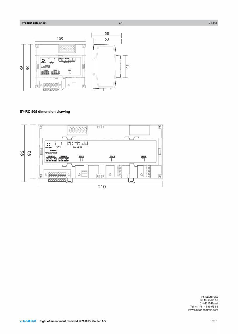
105 53
58
90
96 45ecos504
EY-RC 505 dimension drawing
210
90
96
Product data sheet 7.1 94.112
Right of amendment reserved © 2018 Fr. Sauter AG 17/17
Fr. Sauter AGIm Surinam 55
CH-4016 BaselTel. +41 61 - 695 55 55
www.sauter-controls.com