Embed Size (px)
Citation preview
1
STUART L ITTLE , DIRECTOR OF MARKETING, AVIAT NETWORKS
PETER CROY, SENIOR NETWORK ARCHITECT, AVIAT NETWORKS
HOW CAN IP MICROWAVE MEET THE LTE BACKHAUL CAPACITY CHALLENGE?
Webinar Agenda
• A realistic look at LTE capacity requirements• Options to maximize IP microwave capacity
- Microwave capacity by channel size/modulation- Ethernet transport optimization- Co‐channel operation with XPIC- Link aggregation- Adaptive Coding and Modulation- Millimeter wave systems
• New technology developments- Payload compression- Higher‐order modulation schemes- Multi‐carrier operation- MIMO
• Summary
NOVEMBER 20102 AVIAT NETWORKS |
3
PETER CROY, SR . NETWORK ARCHITECT
LTE BACKHAUL CAPACITY –A TECHNOLOGY PERSPECTIVE
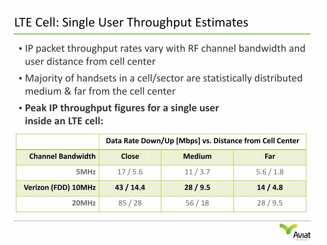
LTE Cell: Single User Throughput Estimates
• IP packet throughput rates vary with RF channel bandwidth and user distance from cell center
• Majority of handsets in a cell/sector are statistically distributed medium & far from the cell center
• Peak IP throughput figures for a single userinside an LTE cell:
Data Rate Down/Up [Mbps] vs. Distance from Cell Center
Channel Bandwidth Close Medium Far
5MHz 17 / 5.6 11 / 3.7 5.6 / 1.8
Verizon (FDD) 10MHz 43 / 14.4 28 / 9.5 14 / 4.8
20MHz 85 / 28 56 / 18 28 / 9.5
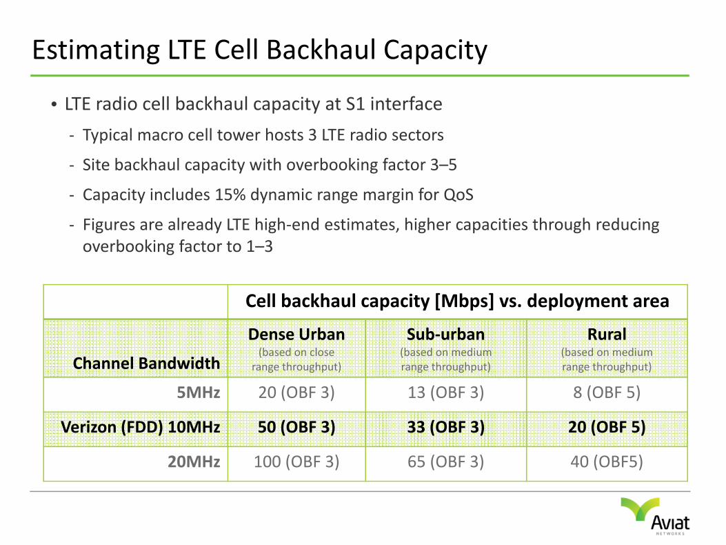
Estimating LTE Cell Backhaul Capacity
• LTE radio cell backhaul capacity at S1 interface
- Typical macro cell tower hosts 3 LTE radio sectors
- Site backhaul capacity with overbooking factor 3–5
- Capacity includes 15% dynamic range margin for QoS
- Figures are already LTE high‐end estimates, higher capacities through reducing overbooking factor to 1–3
Cell backhaul capacity [Mbps] vs. deployment area
Channel Bandwidth
Dense Urban(based on close
range throughput)
Sub‐urban(based on mediumrange throughput)
Rural(based on mediumrange throughput)
5MHz 20 (OBF 3) 13 (OBF 3) 8 (OBF 5)
Verizon (FDD) 10MHz 50 (OBF 3) 33 (OBF 3) 20 (OBF 5)
20MHz 100 (OBF 3) 65 (OBF 3) 40 (OBF5)
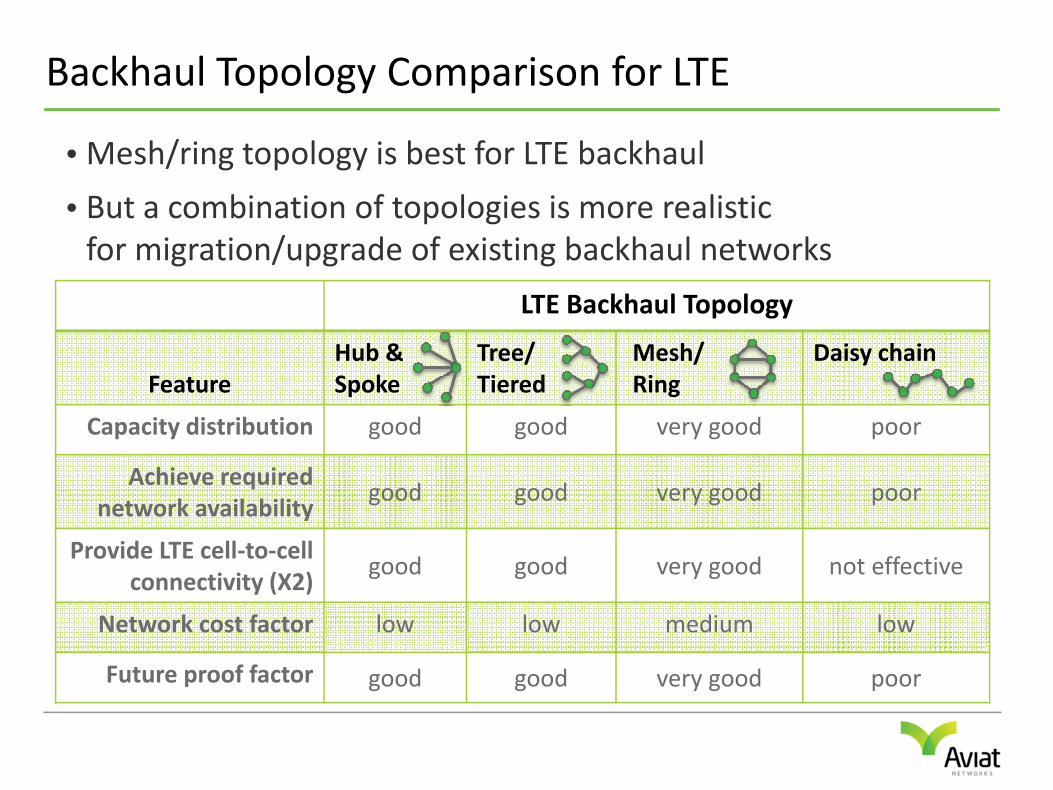
Backhaul Topology Comparison for LTE
• Mesh/ring topology is best for LTE backhaul
• But a combination of topologies is more realisticfor migration/upgrade of existing backhaul networks
LTE Backhaul Topology
FeatureHub & Spoke
Tree/Tiered
Mesh/Ring
Daisy chain
Capacity distribution good good very good poor
Achieve required network availability
good good very good poor
Provide LTE cell‐to‐cell connectivity (X2)
good good very good not effective
Network cost factor low low medium low
Future proof factor good good very good poor
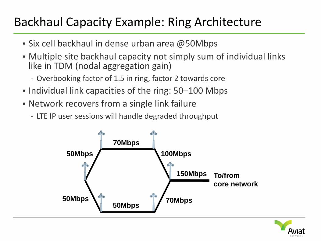
Backhaul Capacity Example: Ring Architecture
• Six cell backhaul in dense urban area @50Mbps• Multiple site backhaul capacity not simply sum of individual links like in TDM (nodal aggregation gain)- Overbooking factor of 1.5 in ring, factor 2 towards core
• Individual link capacities of the ring: 50–100 Mbps• Network recovers from a single link failure
- LTE IP user sessions will handle degraded throughput
To/fromcore network
50Mbps
50Mbps70Mbps
50Mbps70Mbps
100Mbps
150Mbps
MICROWAVE CAPACITY
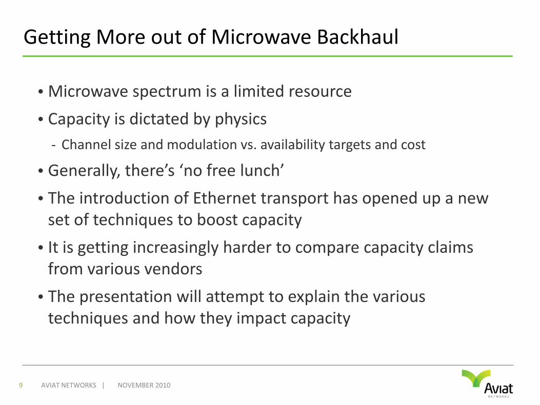
Getting More out of Microwave Backhaul
• Microwave spectrum is a limited resource
• Capacity is dictated by physics- Channel size and modulation vs. availability targets and cost
• Generally, there’s ‘no free lunch’
• The introduction of Ethernet transport has opened up a new set of techniques to boost capacity
• It is getting increasingly harder to compare capacity claims from various vendors
• The presentation will attempt to explain the various techniques and how they impact capacity
NOVEMBER 20109 AVIAT NETWORKS |
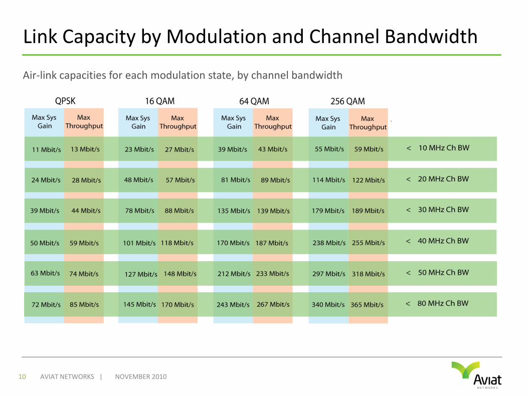
Link Capacity by Modulation and Channel Bandwidth
NOVEMBER 201010 AVIAT NETWORKS |
Air‐link capacities for each modulation state, by channel bandwidth
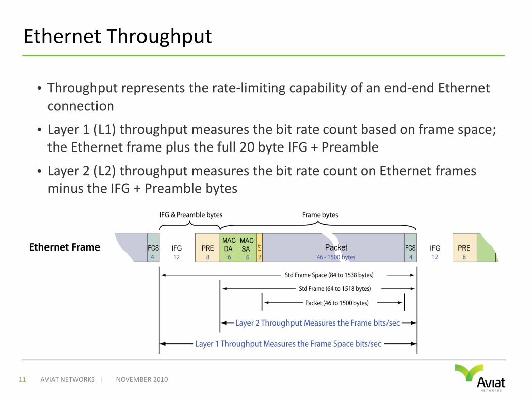
Ethernet Throughput
• Throughput represents the rate‐limiting capability of an end‐end Ethernet connection
• Layer 1 (L1) throughput measures the bit rate count based on frame space; the Ethernet frame plus the full 20 byte IFG + Preamble
• Layer 2 (L2) throughput measures the bit rate count on Ethernet frames minus the IFG + Preamble bytes
NOVEMBER 201011 AVIAT NETWORKS |
Ethernet Frame
Improving Ethernet Throughput
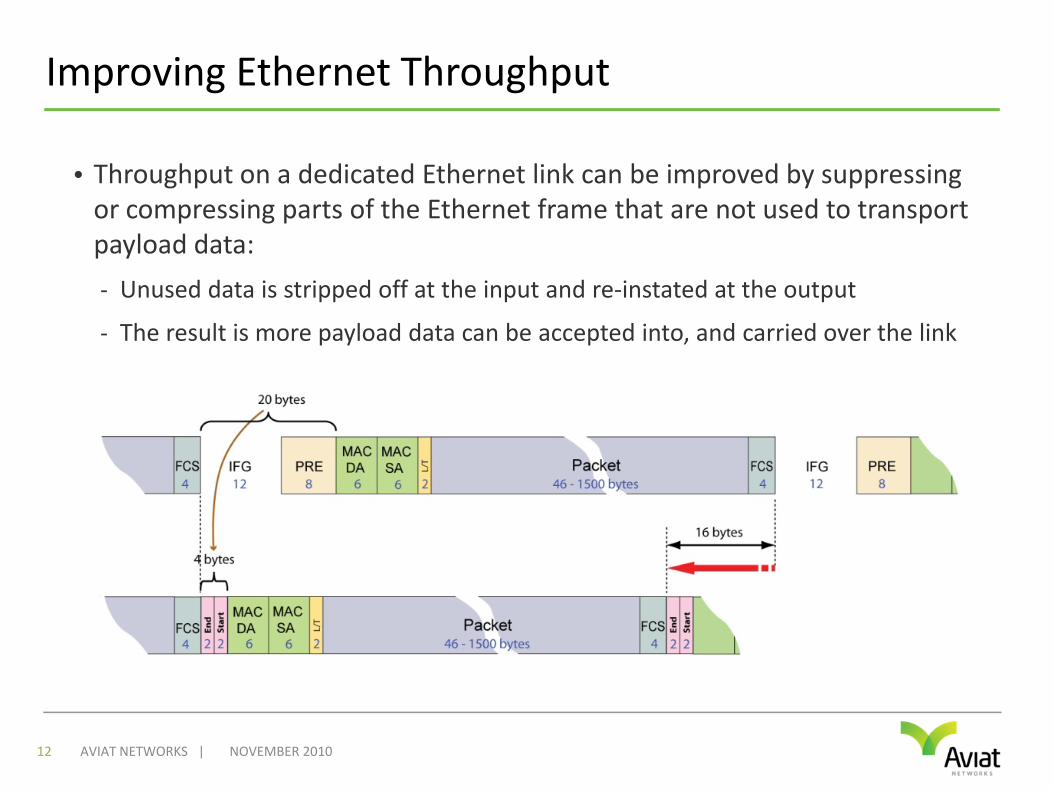
• Throughput on a dedicated Ethernet link can be improved by suppressing or compressing parts of the Ethernet frame that are not used to transport payload data:
- Unused data is stripped off at the input and re‐instated at the output
- The result is more payload data can be accepted into, and carried over the link
NOVEMBER 201012 AVIAT NETWORKS |
Layer 1 vs. Layer 2 Throughput Improvement
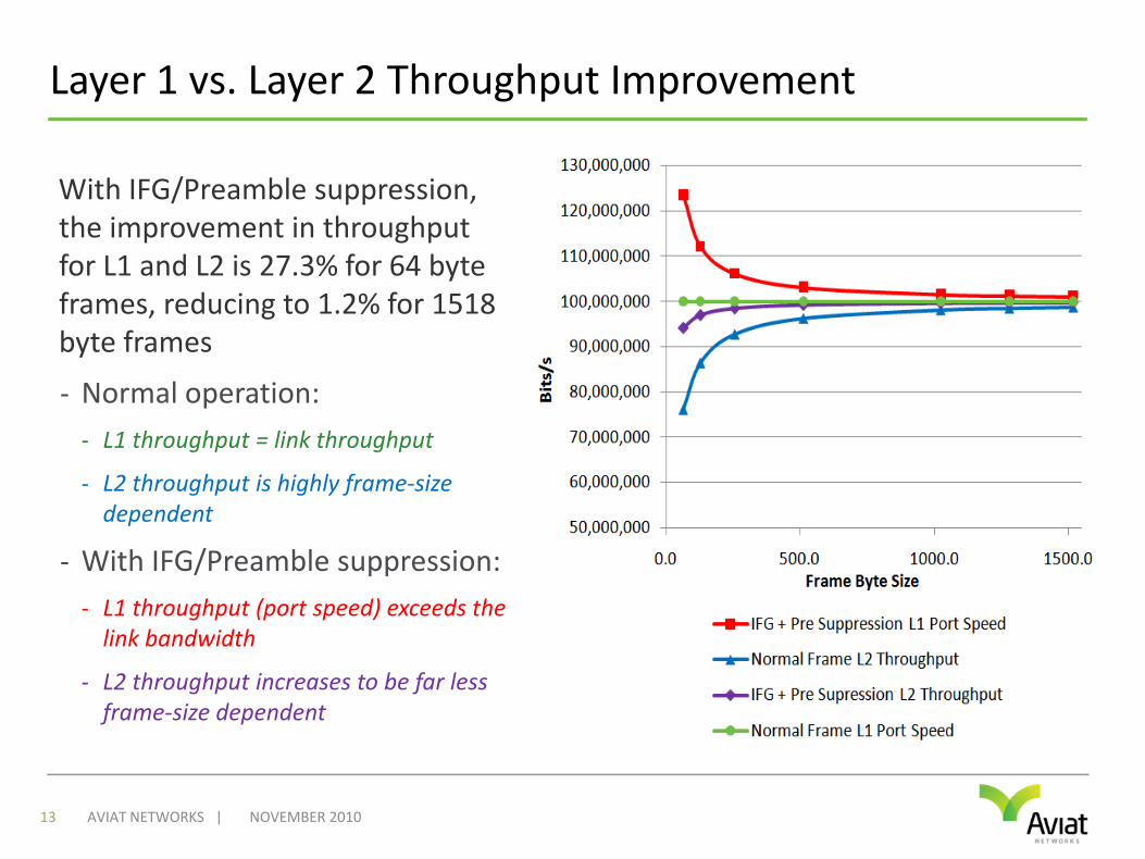
With IFG/Preamble suppression, the improvement in throughput for L1 and L2 is 27.3% for 64 byte frames, reducing to 1.2% for 1518 byte frames
- Normal operation:- L1 throughput = link throughput
- L2 throughput is highly frame‐size dependent
- With IFG/Preamble suppression:- L1 throughput (port speed) exceeds the link bandwidth
- L2 throughput increases to be far less frame‐size dependent
NOVEMBER 2010AVIAT NETWORKS |13
MAC Header Compression (HC)
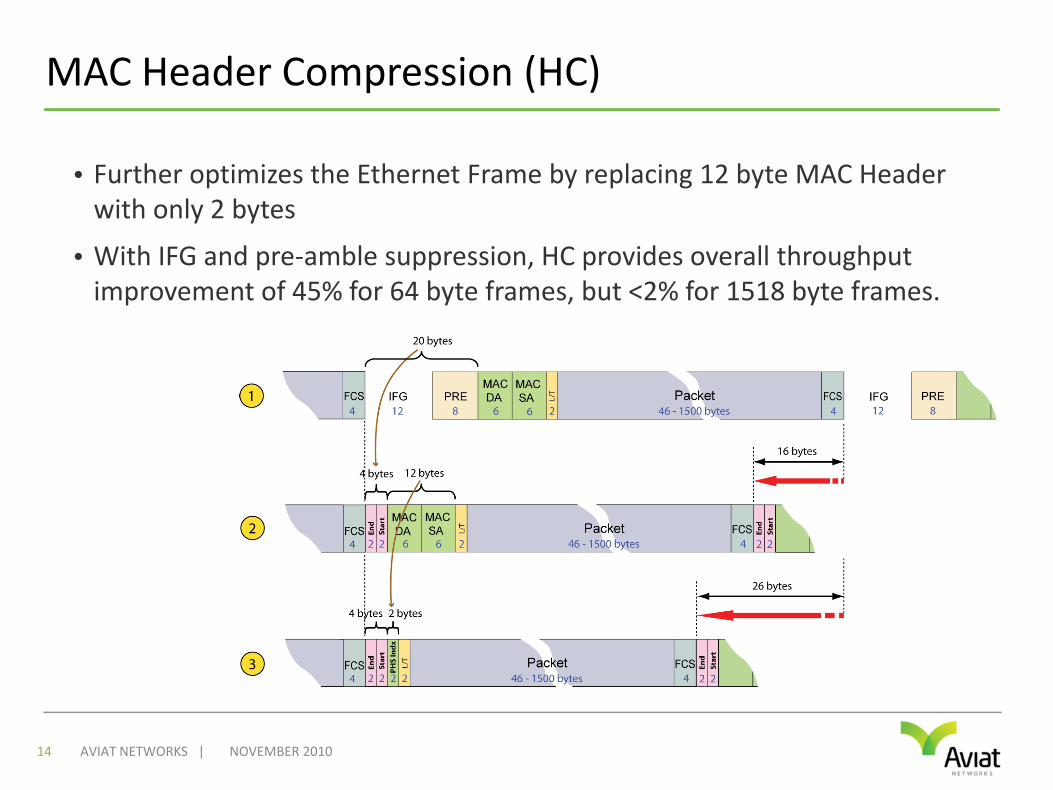
• Further optimizes the Ethernet Frame by replacing 12 byte MAC Header with only 2 bytes
• With IFG and pre‐amble suppression, HC provides overall throughput improvement of 45% for 64 byte frames, but <2% for 1518 byte frames.
NOVEMBER 201014 AVIAT NETWORKS |
Ethernet Throughput Key Points
• Frame suppression or compression techniques can significantly improve throughput on small frames
• BUT, for mid‐ to large‐size frames the benefit is much less
• Throughput can be specified for L1 or L2- Unless otherwise specified, L1 (port utilization speed) figures are normally presented based upon 64 byte frames to provide the best possible throughput figures
- Layer 2 figures more realistically represented Ethernet throughput, as they look only at the Ethernet frame – i.e.: the actual payload capacity
• Ethernet throughput measurement is standardized at L2 using RFC 2544
• Always check to see whether throughput is quoted for L1 or L2!
NOVEMBER 201015 AVIAT NETWORKS |

CO‐CHANNEL OPERATION
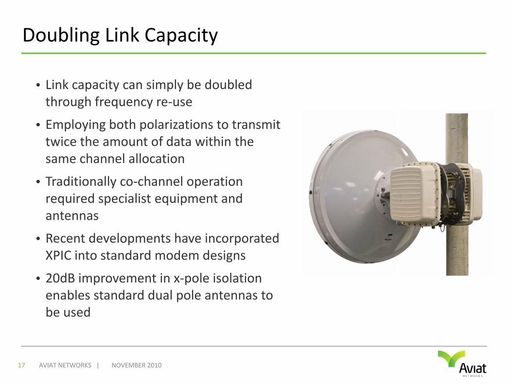
Doubling Link Capacity
• Link capacity can simply be doubled through frequency re‐use
• Employing both polarizations to transmit twice the amount of data within the same channel allocation
• Traditionally co‐channel operation required specialist equipment and antennas
• Recent developments have incorporated XPIC into standard modem designs
• 20dB improvement in x‐pole isolation enables standard dual pole antennas to be used
NOVEMBER 201017 AVIAT NETWORKS |
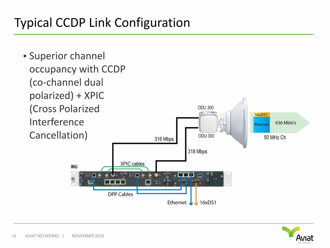
Typical CCDP Link Configuration
NOVEMBER 201018 AVIAT NETWORKS |
• Superior channel occupancy with CCDP (co‐channel dual polarized) + XPIC (Cross Polarized Interference Cancellation)
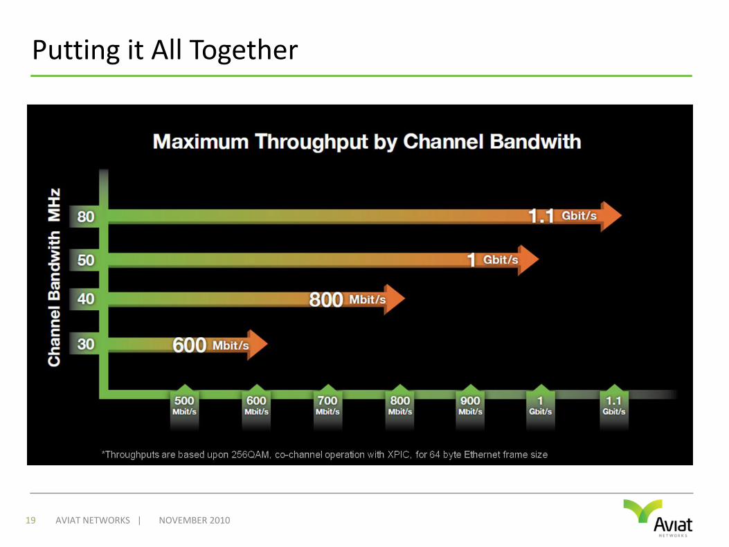
Putting it All Together
NOVEMBER 201019 AVIAT NETWORKS |

LINK AGGREGATION
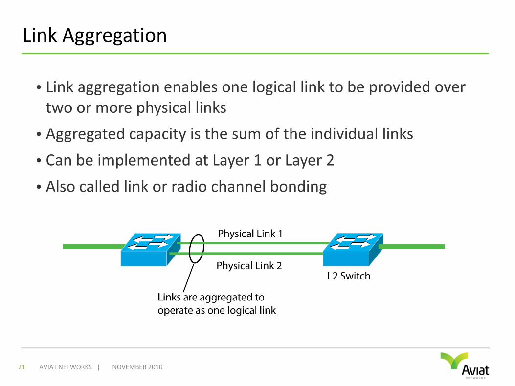
Link Aggregation
• Link aggregation enables one logical link to be provided over two or more physical links
• Aggregated capacity is the sum of the individual links
• Can be implemented at Layer 1 or Layer 2
• Also called link or radio channel bonding
NOVEMBER 201021 AVIAT NETWORKS |
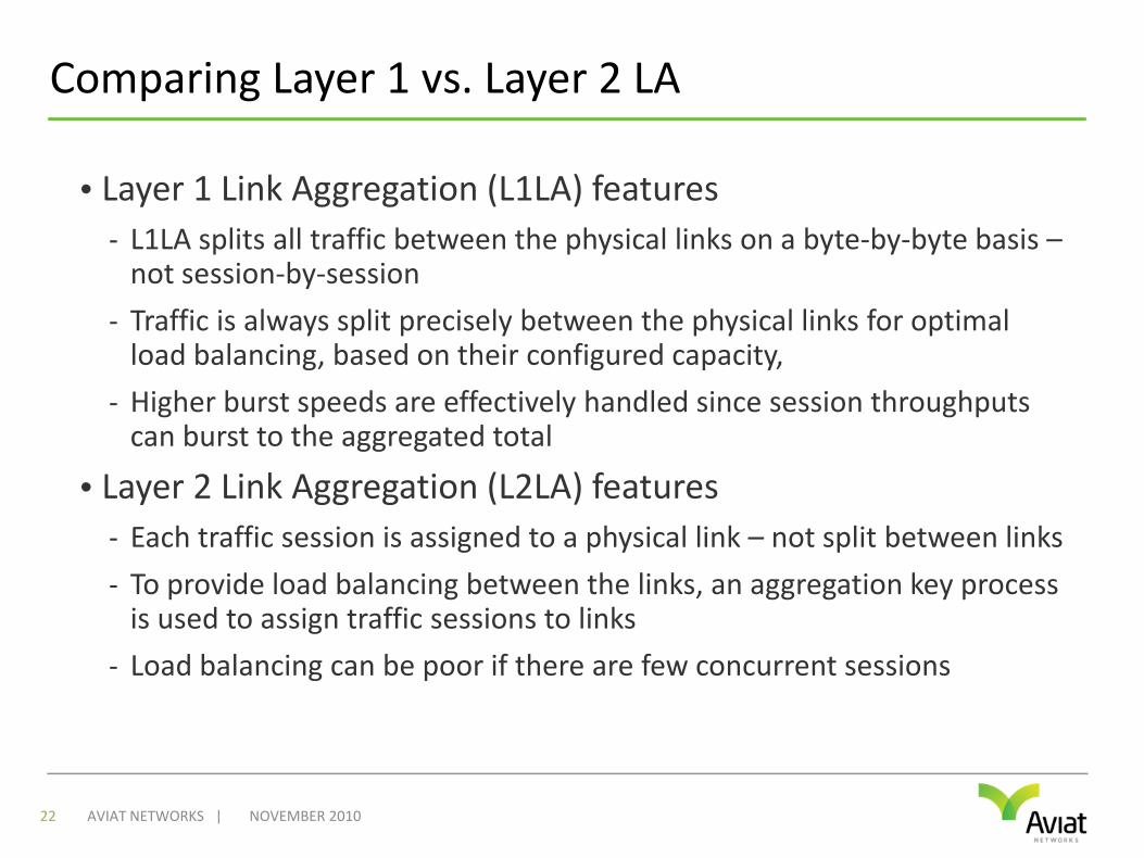
Comparing Layer 1 vs. Layer 2 LA
• Layer 1 Link Aggregation (L1LA) features- L1LA splits all traffic between the physical links on a byte‐by‐byte basis –not session‐by‐session
- Traffic is always split precisely between the physical links for optimal load balancing, based on their configured capacity,
- Higher burst speeds are effectively handled since session throughputs can burst to the aggregated total
• Layer 2 Link Aggregation (L2LA) features- Each traffic session is assigned to a physical link – not split between links- To provide load balancing between the links, an aggregation key process is used to assign traffic sessions to links
- Load balancing can be poor if there are few concurrent sessions
NOVEMBER 201022 AVIAT NETWORKS |
Built‐in N+0 Redundancy
• Link aggregation also provides redundancy• If one of the physical links fails, its traffic is directed onto the remaining link(s)
• Traffic prioritization can be used to ensure all high priority traffic is supported on remaining link capacity
• Provides similar level of redundancy to hot‐standby, but now the standby equipment can be used to pass traffic
• In traditional hot standby protection increases equipment cost by 100%, but the protection channel is rarely if ever used
• Link aggregation provides double the capacity ‐ with built‐in redundancy – eg: 2+0 protection
NOVEMBER 201023 AVIAT NETWORKS |
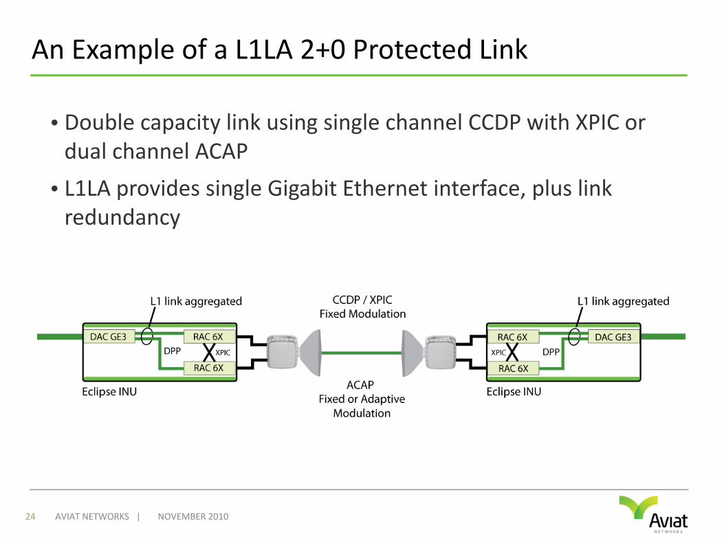
An Example of a L1LA 2+0 Protected Link
• Double capacity link using single channel CCDP with XPIC or dual channel ACAP
• L1LA provides single Gigabit Ethernet interface, plus link redundancy
NOVEMBER 201024 AVIAT NETWORKS |

ADAPTIVE MODULATION
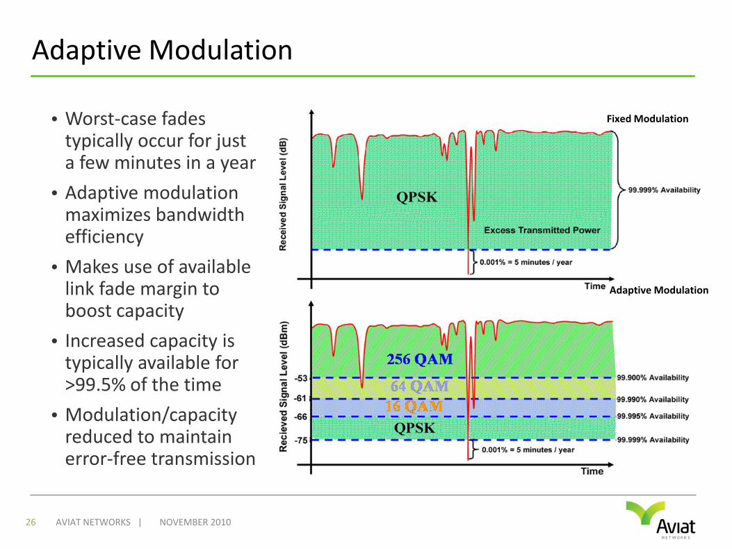
Adaptive Modulation
• Worst‐case fades typically occur for just a few minutes in a year
• Adaptive modulation maximizes bandwidth efficiency
• Makes use of available link fade margin to boost capacity
• Increased capacity is typically available for >99.5% of the time
• Modulation/capacity reduced to maintain error‐free transmission
NOVEMBER 201026 AVIAT NETWORKS |
Fixed Modulation
Adaptive Modulation
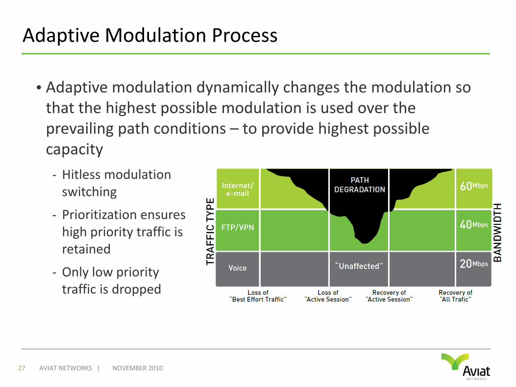
Adaptive Modulation Process
• Adaptive modulation dynamically changes the modulation so that the highest possible modulation is used over the prevailing path conditions – to provide highest possible capacity
NOVEMBER 201027 AVIAT NETWORKS |
- Hitless modulation switching
- Prioritization ensures high priority traffic is retained
- Only low priority traffic is dropped
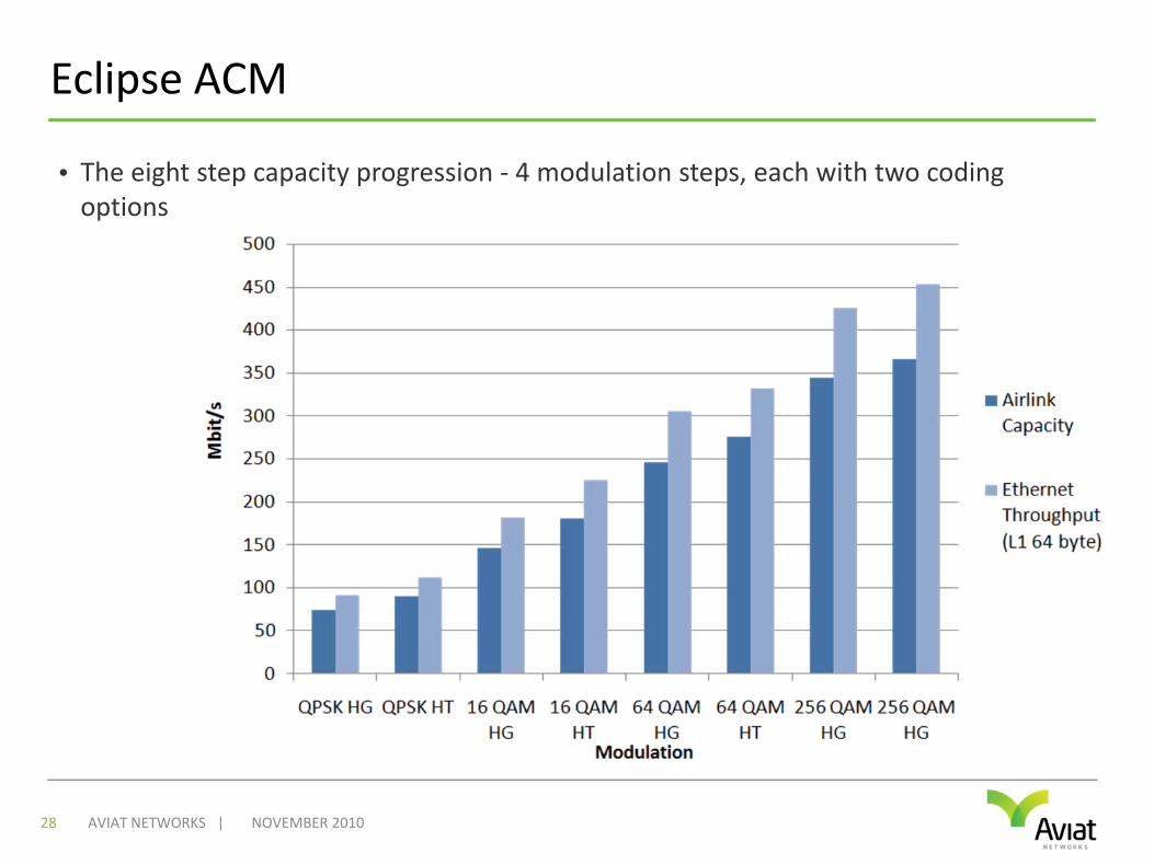
Eclipse ACM
• The eight step capacity progression ‐ 4 modulation steps, each with two coding options
NOVEMBER 201028 AVIAT NETWORKS |
ACM Cost Benefits
• Save on license costs- Annual license costs can double with a doubling of channel bandwidth
- When more capacity is needed use ACM to stay within your existing channel and license
• Save on equipment costs- Higher fixed modulation for more capacity requires larger antennas
- Increased wind loading may require tower strengthening
- Lower CAPEX ‐ smaller antennas are cheaper and easier to install
- Eliminate the need to resize antennas when more capacity is needed
• Save on tower rental costs- Tower rental on third party sites is the highest OPEX contributor
- ACM allows smaller antennas to be used – translates directly to significant OPEX savings
NOVEMBER 201029 AVIAT NETWORKS |

MILLIMETER WAVE
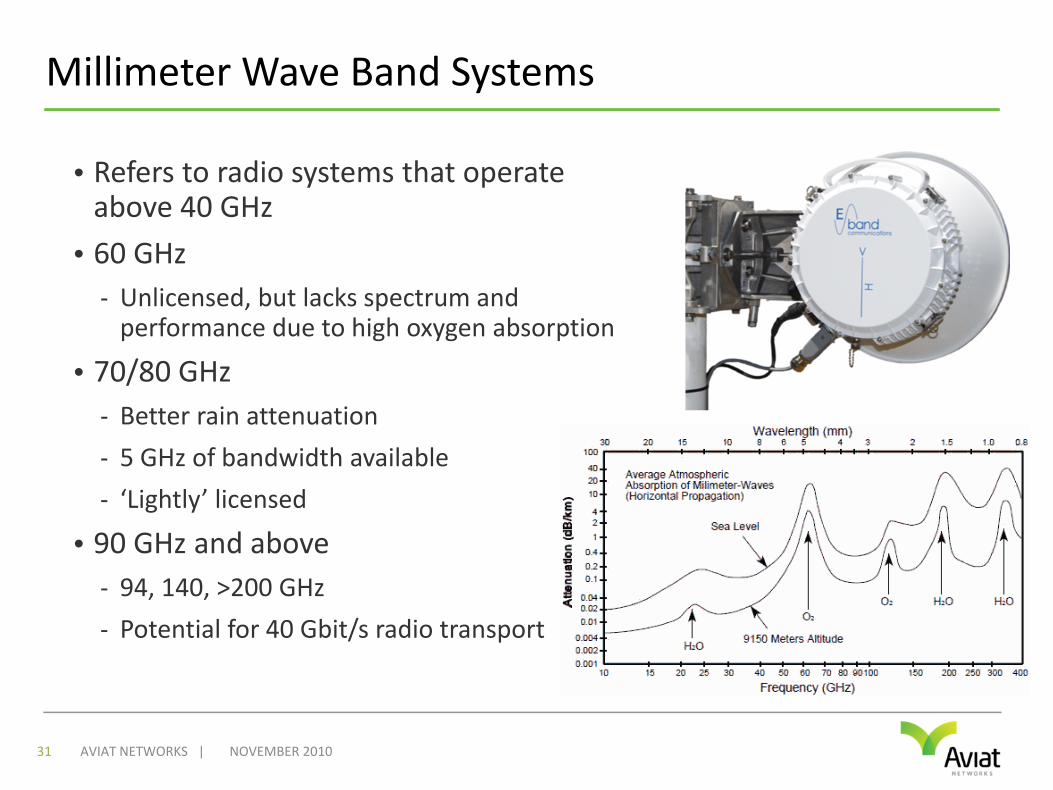
Millimeter Wave Band Systems
• Refers to radio systems that operate above 40 GHz
• 60 GHz- Unlicensed, but lacks spectrum and performance due to high oxygen absorption
• 70/80 GHz- Better rain attenuation
- 5 GHz of bandwidth available
- ‘Lightly’ licensed
• 90 GHz and above- 94, 140, >200 GHz
- Potential for 40 Gbit/s radio transport
NOVEMBER 201031 AVIAT NETWORKS |
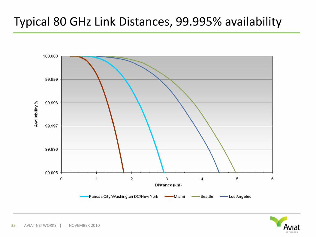
Typical 80 GHz Link Distances, 99.995% availability
NOVEMBER 201032 AVIAT NETWORKS |

LOOKING AHEAD
New Techniques to Further Increase Capacity
• Payload compression
• Higher order modulationschemes
• Multi‐carrier operation
• Multiple‐input, Multiple‐output (MIMO)
NOVEMBER 201034 AVIAT NETWORKS |
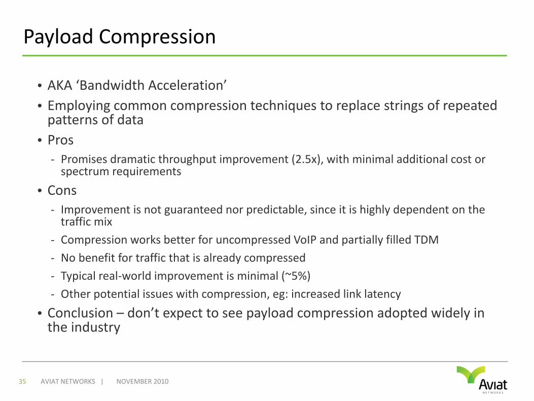
Payload Compression
• AKA ‘Bandwidth Acceleration’• Employing common compression techniques to replace strings of repeated patterns of data
• Pros- Promises dramatic throughput improvement (2.5x), with minimal additional cost or spectrum requirements
• Cons- Improvement is not guaranteed nor predictable, since it is highly dependent on the traffic mix
- Compression works better for uncompressed VoIP and partially filled TDM- No benefit for traffic that is already compressed- Typical real‐world improvement is minimal (~5%)- Other potential issues with compression, eg: increased link latency
• Conclusion – don’t expect to see payload compression adopted widely in the industry
NOVEMBER 201035 AVIAT NETWORKS |
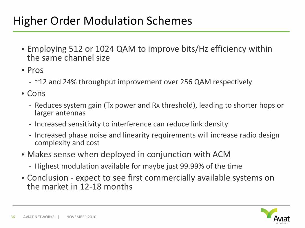
Higher Order Modulation Schemes
• Employing 512 or 1024 QAM to improve bits/Hz efficiency within the same channel size
• Pros- ~12 and 24% throughput improvement over 256 QAM respectively
• Cons- Reduces system gain (Tx power and Rx threshold), leading to shorter hops or larger antennas
- Increased sensitivity to interference can reduce link density- Increased phase noise and linearity requirements will increase radio design complexity and cost
• Makes sense when deployed in conjunction with ACM- Highest modulation available for maybe just 99.99% of the time
• Conclusion ‐ expect to see first commercially available systems on the market in 12‐18 months
NOVEMBER 201036 AVIAT NETWORKS |
Multi‐Carrier
• Employing two modems with a single RF transceiver to transport double capacity in two discrete radio channel
• Pros- Double capacity at small incremental cost
- No need for dual pole antenna, single IF cable run
• Cons- High performance impact – need to back‐off Tx power significantly (>4 dB)
- Only works with more relaxed FCC spectrum masks. Does not meet tighter international ETSI requirements
- Limitations of spectrum arrangements – T‐R and T‐T spacing
• Conclusion – still not widely supported but more products will support this in the future
NOVEMBER 201037 AVIAT NETWORKS |
MIMO
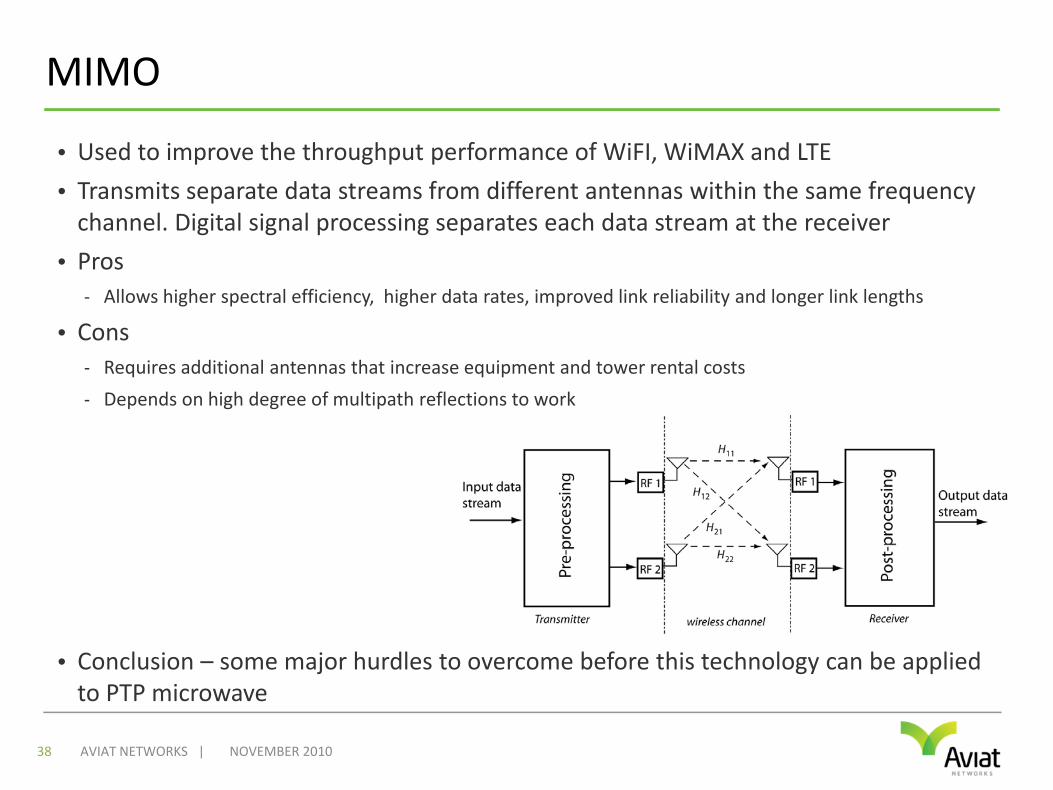
• Used to improve the throughput performance of WiFI, WiMAX and LTE
• Transmits separate data streams from different antennas within the same frequency channel. Digital signal processing separates each data stream at the receiver
• Pros- Allows higher spectral efficiency, higher data rates, improved link reliability and longer link lengths
• Cons- Requires additional antennas that increase equipment and tower rental costs
- Depends on high degree of multipath reflections to work
• Conclusion – some major hurdles to overcome before this technology can be applied to PTP microwave
NOVEMBER 201038 AVIAT NETWORKS |
CONCLUSIONS

In Conclusion
• LTE is again suffering from the same capacity hype that was prevalent when 3G was first introduced
• Microwave transport meets the foreseeable capacity needs for mobile backhaul for several years to come
• The transition to IP has opened up many new and reliable techniques to make more of existing licensed spectrum
• Millimeter wave bands promise fiber‐like capacities over short distance, cost‐effective links
• New technologies are now being researched that promise further capacity enhancements over the next 2‐3 years

WWW.AVIATNETWORKS.COM