Embed Size (px)
Citation preview

World Housing Encyclopedia an Encyclopedia of Housing Construction in
Seismically Active Areas of the World
an initiative of Earthquake Engineering Research Institute (EERI) and
International Association for Earthquake Engineering (IAEE)
HOUSING REPORT Mud wall construction in Spiti Valley
(Himachal Pradesh)
Report # 171
Report Date 05-08-2012
Country INDIA
Housing Type Adobe / Earthen House
Housing Sub-Type Adobe / Earthen House: Rammed earth/Pise construction
Authors Ankita Sood, Aditya Rahul, Yogendra Singh, Dominik H. Lang
Reviewer Qaisar Ali
Important This encyclopedia contains information contributed by various earthquake engineering professionals around the world. All opinions, findings, conclusions & recommendations expressed herein are those of the various participants, and do not necessarily reflect the views of the Earthquake Engineering Research Institute, the International Association for Earthquake Engineering, the Engineering Information Foundation, John A. Martin & Associates, Inc. or the participants' organizations.

Summary
This report describes a building type found in Himachal Pradesh, a northern state in India. It is concentrated in the upper reaches of the state in the Lahaul and Spiti districts, which are located in a cold-desert area with very hot days and chilling nights. Precipitation usually only occurs in the form of snowfall with almost no to very little rainfall. This dryness of the local climate is reflected in the architecture of this construction typology which consists of thick mud walls with small openings in order to insulate the interior from the harsh outside climate. This style of construction which is predominantly used for residential houses and temples is still being practiced though it shows high seismic vulnerability.
1. General Information
Buildings of this construction type can be found in the Spiti river valley of the districts Lahaul and Spiti, in the state of Himachal Pradesh (Figure 1, Figure 2). As a specific term has not yet been coined for these houses, it was decided to name this construction type ‘Spitian architecture’. The addressed region is a desert area where timber is scarce and mud is the main locally available construction material. The addressed buildings are therefore made of rammed earthen walls and timber is solely used for floors and roofs as well as for door and window frames. Natural stones are also scarce and are thus only used for foundations. This type of housing construction is commonly found in both rural and sub-urban areas. This construction type has been in practice for more than 200 years.
Currently, this type of construction is being built. The earliest good example is an 800 year-old Kii gompa (monastery) in the village Kii (Figure 3). This type of construction is still the main construction typology in the area.
Figure 1. Typical Spitian mud house of 2 storeys.

Figure 2. Location of the investigation area in Lahaul and Spiti districts of state Himachal Pradesh, northern India.
Figure 3. View of Kii monastry in village Kii in Lahaul and Spiti district of Himachal Pradesh.

2. Architectural Aspects
2.1 Siting These buildings are typically found on both sloped and hilly terrain. They do not share common walls with adjacent buildings. Houses in the valley are built on flat lands while those on slopes and ridges are located on flat plateaus that are artificially cut into the topographical feature. In the Spiti river valley, the village Lossar is characterized by an entirely flat topography (Figure 4) whereas the village Kibber is located on slopes (Figure 5 and Figure 6). When separated from adjacent buildings, the typical distance from a neighboring building is a minimum of 0.3 meters.
2.2 Building Configuration The houses are generally rectangular in plan without any verandah. A typical house is of two to three storeys with the lower storey used for cattle and the upper storey(s) for the family. Openings are generally of small size. In some cases, skylights are provided in the roof in order to provide natural light to the interior corridors and staircases (Figure 7 and Figure 8).
2.3 Functional Planning The main function of this building typology is a single-family house. In a typical building of this type, there are no elevators and no fire-protected exit staircases. The typical building has generally one door other than the main entrance door which can be considered as an escape route at the buildings rear. On contoured sites, these doors may be located at different levels (Figure 9).
2.4 Modification to Building It is assumed that buildings of Spitian architecture were designed and constructed under the influence of one particular architectural school that prioritized human comfort in the harsh weather conditions while being constricted to using locally available materials. In recent times, various experiments of construction using conventional building materials (bricks) have failed as these materials do not provide the same advantages with respect to insulation (both during winter and during summer) as mud. However, more contemporary materials have found their way into many Spitian houses, e.g. pre-cast RC lintels (Figure 10) which replace wooden lintels. The small open-to-sky-and-sun bath spaces (Figure 11) were recently replaced by enclosed winter gardens with large glass windows. A new variant can also be found in some places where single RC columns and beams are arranged (Figure 12).
Figure 4. Houses located on flat topography in the village Kii.

Figure 5. Houses located on slopes.
Figure 6. Houses built on hilly slopes in the village Kibber.
Figure 7. Sky-light as seen from terrace.
Figure 8. Light pouring in through sky-light above.
Figure 9. Doors at different levels.
Figure 10. Precast RC lintels in a new construction.

Figure 11. A small open-to-sky sun bath space at first floor level
of an older house.
Figure 12. RC framed structure with mud walls infill and mud
roof.
3. Structural Details
3.1 Structural System
Material Type of Load-Bearing Structure # Subtypes Most appropriate type
Masonry
Stone Masonry Walls
1Rubble stone (field stone) in mud/lime mortar or without mortar (usually with timber roof) ☐
2 Dressed stone masonry (in lime/cement mortar) ☐
Adobe/ Earthen Walls
3 Mud walls ☐
4 Mud walls with horizontal wood elements ☐
5 Adobe block walls ☐
6 Rammed earth/Pise construction ☑
Unreinforced masonry walls
7 Brick masonry in mud/lime mortar ☐
8 Brick masonry in mud/lime mortar with vertical posts ☐
9 Brick masonry in lime/cement mortar ☐
10 Concrete block masonry in cement mortar ☐
Confined masonry
11 Clay brick/tile masonry, with wooden posts and beams ☐
12 Clay brick masonry, with concrete posts/tie columnsand beams ☐
13 Concrete blocks, tie columns and beams ☐
Reinforced masonry 14 Stone masonry in cement mortar ☐
15 Clay brick masonry in cement mortar ☐
16 Concrete block masonry in cement mortar ☐

Material Type of Load-Bearing Structure # Subtypes Most appropriate type
Structural concrete
Moment resisting frame
17 Flat slab structure ☐
18 Designed for gravity loads only, with URM infill walls ☐
19 Designed for seismic effects, with URM infill walls ☐
20 Designed for seismic effects, with structural infill walls ☐
21 Dual system – Frame with shear wall ☐
Structural wall 22 Moment frame with in-situ shear walls ☐
23 Moment frame with precast shear walls ☐
Precast concrete
24 Moment frame ☐
25 Prestressed moment frame with shear walls ☐
26 Large panel precast walls ☐
27 Shear wall structure with walls cast-in-situ ☐
28 Shear wall structure with precast wall panel structure ☐
Steel
Moment-resisting frame
29 With brick masonry partitions ☐
30 With cast in-situ concrete walls ☐
31 With lightweight partitions ☐
Braced frame 32 Concentric connections in all panels ☐
33 Eccentric connections in a few panels ☐
Structural wall 34 Bolted plate ☐
35 Welded plate ☐
Timber Load-bearing timber frame
36 Thatch ☐
37 Walls with bamboo/reed mesh and post (Wattle and Daub) ☐
38 Masonry with horizontal beams/planks at intermediate levels ☐
39 Post and beam frame (no special connections) ☐
40 Wood frame (with special connections) ☐
41 Stud-wall frame with plywood/gypsum board sheathing ☐
42 Wooden panel walls ☐
Other Seismic protection systems
43 Building protected with base-isolation systems ☐
44 Building protected with seismic dampers ☐
Hybrid systems 45 other (described below) ☐
3.2 Gravity Load-Resisting System The vertical load-resisting system is earthen walls. The vertical load-resisting system consists of 300 - 500 mm wide walls made of rammed earth resting on a foundation base made of undressed field stones with mud mortar.
3.3 Lateral Load-Resisting System The lateral load-resisting system is earthen walls. The same 300 - 500 mm wide walls made of rammed earth, which are basically constructed to resist the gravity load, also constitute the lateral load resisting system. The walls have practically no tensile strength and very little shear strength resulting in extremely poor in-plane and out-of-plane resistance against lateral loads.

3.4 Building Dimensions The typical plan dimensions of these buildings are: lengths between 8 and 12 meters, and widths between 3 and 10 meters. The building has 2 to 3 storeys. The typical span of the roofing/flooring system is smaller or equal to 4 meters. The typical storey height in such buildings is 2.5 meters. The typical structural wall density is more than 20 %.
3.5 Floor and Roof System Material Description of floor/roof system Most appropriate floor Most appropriate roof
Masonry Vaulted ☐ ☐
Composite system of concrete joists and masonry panels ☐ ☐
Structural concrete
Solid slabs (cast-in-place) ☐ ☐
Waffle slabs (cast-in-place) ☐ ☐
Flat slabs (cast-in-place) ☐ ☐
Precast joist system ☐ ☐
Hollow core slab (precast) ☐ ☐
Solid slabs (precast) ☐ ☐
Beams and planks (precast) with concrete topping (cast-in-situ) ☐ ☐
Slabs (post-tensioned) ☐ ☐
Steel Composite steel deck with concrete slab (cast-in-situ) ☐ ☐
Timber
Rammed earth with ballast and concrete or plaster finishing ☐ ☐
Wood planks or beams with ballast and concrete or plaster finishing ☑ ☑
Thatched roof supported on wood purlins ☐ ☑
Wood shingle roof ☐ ☐
Wood planks or beams that support clay tiles ☐ ☐
Wood planks or beams supporting natural stones slates ☐ ☑Wood planks or beams that support slate, metal, asbestos-cement or plastic corrugated sheets or tiles ☐ ☐ Wood plank, plywood or manufactured wood panels on joists supported by beams or walls ☐ ☐
Other Described below ☑ ☑

3.6 Foundation Type Description Most appropriate type
Shallow foundation
Wall or column embedded in soil, without footing ☐
Rubble stone, fieldstone isolated footing ☐
Rubble stone, fieldstone strip footing ☑
Reinforced-concrete isolated footing ☐
Reinforced-concrete strip footing ☐
Mat foundation ☐
No foundation ☐
Deep foundation
Reinforced-concrete bearing piles ☐
Reinforced-concrete skin friction piles ☐
Steel bearing piles ☐
Steel skin friction piles ☐
Wood piles ☐
Cast-in-place concrete piers ☐
Caissons ☐
Other Described below ☐
Locally available stone is used for foundation. A trench is dug about 300 mm in depth and 500 mm in width. Courses of stones with mud mortar are then laid in the trench up to the ground level. The same courses are then taken up to 600 to 900 mm above the ground in order to form the lower portion of the walls. Through this procedure the walls are protected from direct rain water splashes and snow. Generally, there is no plinth in these houses (Figure 13).
Figure 13. Lower portion of the wall made up of field stones. The front door is arranged at ground floor level without any plinth.
4. Socio-Economic Aspects
4.1 Number of Housing Units and Inhabitants Each building typically has 1 housing unit. Generally, the building is occupied by one family only. The number of inhabitants in a building during the day or business hours is less than 5. The number of inhabitants during the evening and night is 5-10. These numbers apply to the summer months. During winters, the number of inhabitants in a building during the day and during the night is less than five as the young people move to other places, mainly Delhi and Goa, for work.
4.2 Patterns of Occupancy In large houses, the ground floor is generally used for cattle or as storage space. The first floor has a living/prayer room, 1 or 2 bedrooms, a kitchen and a toilet. In houses with three storeys, the entire top floor is used as a prayer room. The occupancy pattern changes in winters, when the inhabitants also move to the cozy ground floor. Houses have a small front yard (Figure 14) for household chores and to keep the cattle (yaks).
4.3 Economic Level of Inhabitants Income class Most appropriate type
a) very low-income class (very poor) ☑
b) low-income class (poor) ☑
c) middle-income class ☑
d) high-income class (rich) ☑
Ratio of housing unit price to annual income Most appropriate type
5:1 or worse ☐
4:1 ☑
3:1 ☐
1:1 or better ☐
What is a typical source of financing for buildings of this type? Most appropriate type
Owner financed ☑
Personal savings ☑
Informal network: friends and relatives ☑
Small lending institutions / micro-finance institutions ☐
Commercial banks/mortgages ☐
Employers ☐
Investment pools ☐
Government-owned housing ☐
Combination (explain below) ☐
other (explain below) ☐
In each housing unit, there is 1 bathroom without toilet and 1 toilet only.
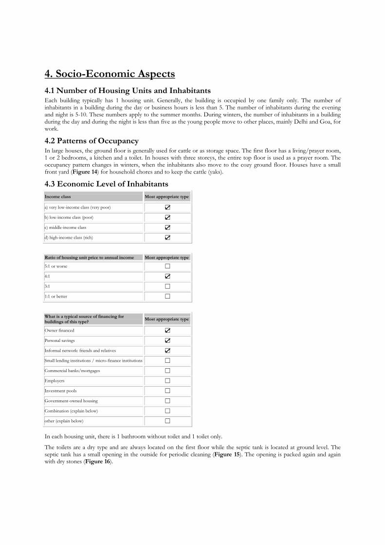
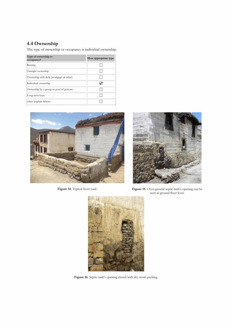
The toilets are a dry type and are always located on the first floor while the septic tank is located at ground level. The septic tank has a small opening in the outside for periodic cleaning (Figure 15). The opening is packed again and again with dry stones (Figure 16).
4.4 Ownership The type of ownership or occupancy is individual ownership.
Type of ownership or occupancy? Most appropriate type
Renting ☐
Outright ownership ☐
Ownership with debt (mortgage or other) ☐
Individual ownership ☑
Ownership by a group or pool of persons ☐
Long-term lease ☐
other (explain below) ☐
Figure 14. Typical front yard.
Figure 15. Over-ground septic tank's opening can be seen at ground floor level.
Figure 16. Septic tank's opening closed with dry stone packing.

5. Seismic Vulnerability
5.1 Structural and Architectural Features Structural/ Architectural Feature
Statement Most appropriate type
True False N/A
Lateral load path The structure contains a complete load path for seismic force effects from any horizontal direction that serves to transfer inertial forces from the building to the foundation.
☑ ☐ ☐
Building Configuration The building is regular with regards to both the plan and the elevation. ☑ ☐ ☐
Roof construction The roof diaphragm is considered to be rigid and it is expected that the roof structure will maintain its integrity, i.e. shape and form, during an earthquake of intensity expected in this area.
☐ ☑ ☐
Floor construction The floor diaphragm(s) are considered to be rigid and it is expected that the floor structure(s) will maintain its integrity during an earthquake of intensity expected in this area.
☐ ☑ ☐
Foundation performance There is no evidence of excessive foundation movement (e.g. settlement) that would affect the integrity or performance of the structure in an earthquake. ☑ ☐ ☐
Wall and frame structures - redundancy The number of lines of walls or frames in each principal direction is greater than or equal to 2. ☑ ☐ ☐
Wall proportions Height-to-thickness ratio of the shear walls at each floor level is: Less than 25 (concrete walls); Less than 30 (reinforced masonry walls); Less than 13 (unreinforced masonry walls);
☐ ☐ ☑
Foundation-wall connection Vertical load-bearing elements (columns, walls) are attached to the foundations; concrete columns and walls are doweled into the foundation. ☐ ☑ ☐
Wall-roof connections Exterior walls are anchored for out-of-plane seismic effects at each diaphragm level with metal anchors or straps ☐ ☑ ☐
Wall openings
The total width of door and window openings in a wall is:For brick masonry construction in cement mortar : less than ½ of the distance between the adjacent cross walls; For adobe masonry, stone masonry and brick masonry in mud mortar: less than 1/3 of the distance between the adjacent cross walls; For precast concrete wall structures: less than 3/4 of the length of a perimeter wall.
☑ ☐ ☐
Quality of building materials Quality of building materials is considered to be adequate per the requirements of national codes and standards (an estimate). ☐ ☑ ☐
Quality of workmanship Quality of workmanship (based on visual inspection of few typical buildings) is considered to be good (per local construction standards). ☐ ☑ ☐
Maintenance Buildings of this type are generally well maintained and there are no visible signs of deterioration of building elements (concrete, steel, timber) ☐ ☑ ☐
5.2 Seismic Features
Structural element Seismic Deficiency
Earthquake Resilient Features
Earthquake Damage Patterns
Wall The walls are made of rammed earth which has very little shear and bending strength. The flexible floors and roofs are also simply resting over the walls. In some cases opening
sizes are also quite large.
-- Not known during any past earthquake. But it is
expected that the walls will fail in out-of-plane action.
Roof and floors Roof and floors are made of wooden girders, without any
bracing or measure to prevent the relative movement. -- Not known during any past earthquake. But it is
expected that the wooden girders will move relative to each other and relative to walls, resulting in the collapse
of floors/roof.
5.3 Overall Seismic Vulnerability Rating
The overall rating of the seismic vulnerability of the housing type is A: HIGH VULNERABILITY (i.e., very poor seismic performance), the lower bound (i.e., the worst possible) is A: HIGH VULNERABILITY (i.e., very poor seismic performance), and the upper bound (i.e., the best possible) is A: HIGH VULNERABILITY (i.e., very poor seismic performance).

Vulnerability High medium-high medium medium-low low very low
very poor poor moderate good very good excellent
Vulnerability Class A B C D E F ☑ ☐ ☐ ☐ ☐ ☐
5.4 History of Past Earthquakes
Date Epicenter, region Magnitude Max. Intensity
1555 Kashmir > Mw 7.0
1720 Kumaun > M 8.0
1803 Garwhal Mw 8.09
1855 Shrinigar (Kashmir) Mw 6.3
1905 Kangra (Himachal Pradesh) Mw 7.8 IX
1974 Pattan Mw 6.2
1981 Karakoram, Darel, Tangir, Khanbari valleys M 6.2
1991 Uttarkashi (Uttarakhand) Mw 6.8, mb 6.1 (IMD), Ms 7.1 (USGS) I (MMI) = VIII
1999 Chamoli (Gharwal region) Mw 6.4, Ms 6.6, ml 6.8 (IMD), mb 6.3 (USGS) I (MMI) = VIII
2005 Muzzafarabad (Kashmir) Mw 7.6 X to XII
References: Hicyilmaz et al. (2012), Rautela et al. (2009)
Comment on structural vulnerability: The structural configuration of these buildings is quite regular. Further, these buildings have a complete and direct load path in the form of thick mud walls. The main source of deficiency in these buildings lies in their main construction material, i.e. rammed earth, which has poor in-plane and out-of-plane resistance against lateral loads. The geographical area, which is characterized by very difficult geo-environmental conditions, has a scarcity of any other construction material. At the same time, the region is remotely located and not well connected with the mainland, making the transportation of better (in terms of more seismically resilient) construction materials very difficult and costly. The flexible roof system also adds to the vulnerability as it provides no lateral restraint to the walls in the out-of-plane direction. As a result, the walls act as vertical cantilevers above the foundation, and are highly prone to failure in out-of-plane action. Nevertheless, the seismic vulnerability could be significantly reduced by using some simple strengthening measures which would involve the use of a little amount of timber in the walls and bracing of the roof girders.

6. Construction
6.1 Building Materials Structural element Building material Characteristic strength Mix proportions/dimensions Comments Walls Locally available mud No standard values available. No measurements available.
Foundation Field stones Not possible to be obtained.
Frames (beams & columns) NA Roof and floor(s) Wood, mud Wood: depending on local quality. Not possible to be obtained.
6.2 Builder Construction is carried out under the surveillance of the owner himself.
6.3 Construction Process, Problems and Phasing Wall System: Houses of Spitian architecture have a load-bearing wall system. The 300 - 500 mm thick mud walls take up the entire load. Construction materials: The foundations and walls up to 600 to 900 mm height above the ground level are made of local available field stones. Above this base, the walls are entirely constructed of rammed earth. Construction methodology of walls: Step 1 - A wooden formwork is assembled and kept at place over the stone courses of the wall. This formwork has two wooden planks laid parallel to each other at a distance of either 300 or 500 mm and is secured at place by wooden screws and members (Figure 17). The height of the planks is generally 300 mm. Step 2 - In order to lay the first course of the mud wall, the formwork is filled with mud and rammed properly with a mallet. Once the mud sets at place, the formwork is slid further in order to make the other portions of the wall. The same procedure is repeated until the whole course of all four walls is finished. Thus a course of about 300 mm height has been prepared. Through the same procedure courses are laid one over the other in order to construct the entire wall. During the summer, it is possible to do two courses per day. In winter, only one course is laid per day and then allowed to dry/harden overnight. The horizontal borderline between two individual courses can be clearly seen on the walls. Lintel beams are placed at appropriate height during the wall construction. Step 3 - Once the walls are made and dried properly, windows of appropriate and desired size can be cut into them (Figure 18). In case of scarcity of mud, window frames are arranged in place while laying the courses (Figure 19). Step 4 - The walls are finished with a mud slurry allowing for organic design patterns and finally are white washed. The lines of individual courses are still visible after finishing (Figure 20). The walls of these houses are thicker at the bottom and thinner at the top. This is not done intentionally but since one course is laid over the other before fully drying, the lower courses of the wall spread out a bit under the weight of the upper courses. Thus the bottommost course is widest while the course at the top is thinnest. This phenomenon results in somewhat better stability of the walls.
Floor system and roof typology: Ground floor - The flooring at ground floor level consists of only an earth fill which is finished with mud slurry. Upper floors - Wooden beams are laid across the walls in one direction only. These are secured in place with mud only. The distance between the beams is kept small considering the strength and weight of the overlaying material. Tree branches and wooden planks are densely laid over them and then a 50 mm thick layer of mud is spread over it (Figure 21). Roof - As the area has very little or no rainfall, the roofs are flat and constructed in the same way as the floors. Nowadays, with somewhat improved connectivity for transportation, poplar tree logs or steel sections are sometimes used for the beams as well (Figure 22). Parapets - To construct the parapets, a 300 mm thick and 300 mm high course of mud is laid at the periphery of the terrace. On top of it, dried bushes are packed densely (Figure 23). These bushes are projecting to the outside and hence also act as a sunshade (Figure 24).
The construction of this type of housing takes place in a single phase.
Typically, the building is originally designed for its final constructed size.
6.4 Design and Construction Expertise Local masons are involved in the construction of these buildings, inheriting their skills from their fathers. Architects and engineers are not involved in the design or construction of this housing type.
6.5 Building Codes and Standards This construction type is not addressed by the codes/standards of the country. However, an Indian code for improving earthquake resistance of earthen buildings (IS 13827 : 1993) exists and the provisions are applicable to this type of construction as well. The main provisions of the code recommend the provision of: (i) a wooden band at lintel level, (ii)

pillars and buttresses in long walls, (ii) vertical (cane or bamboo) reinforcement, (iii) diagonal wooden members at the corners, and (iii) diagonal bracings between roof/floor girders to avoid their relative movement.
6.6 Building Permits and Development Control Rules This type of construction is non-engineered, and authorized as per development control rules. Building permits are not required to build this housing type.
6.7 Building Maintenance Typically, the building of this housing type is maintained by the Owner(s). Exteriors are coated with mud-slurry once or twice a year whereas interiors are coated with the same more frequently for cleanliness.
6.8 Construction Economics The construction of these buildings is the only efficient option in the valley as the main building material mud is easily available and also suits to the harsh weather conditions.
Figure 17. Wooden formwork to lay courses of mud.
Figure 18. Marks can be seen on the wall of the upper floor where windows have to be cut. Lintel beams have already been provided
during the wall construction process.
Figure 19. Walls with already placed window frames.
Figure 20. Patterns made to the outer walls with mud slurry for finishing.

Figure 21. Branches are densely laid over poplar tree logs (beams).
Figure 22. A steel I-section girder is used to support the beams.
Figure 23. Parapet over a Spitian house terrace.
Figure 24. Bushes projecting outwards, hence forming a type of sunshade/roof projection.
7. Insurance
Earthquake insurance for this construction type is typically unavailable. An insurance premium discount or more complete coverage for seismically strengthened existing buildings or new buildings incorporating seismically resilient features is not relevant.
8. Strengthening
8.1 Description of Seismic Strengthening Provisions
Strengthening of Existing Construction: Seismic Deficiency Description of Seismic Strengthening provisions used
Low in-plane and out-of-plane strength of mud walls
The walls can be supported in-plane using a braced frame system. The posts of the braced frame will support the roof beams directly, so that even if the walls fail during an earthquake, collapse of the roof is avoided. The diagonal bracing in the frame provides the required in-plane strength to the walls. Wooden ties can be located at roof, lintel and sill levels on both sides of the walls to support them in out-of-plane action (Figure 25). The corners of walls and joints of girders with vertical posts can also be strengthened using diagonal bracings. This provides a resilient alternative system to resist vertical and lateral loads in the form of the wooden frame, duly braced in all directions.
Flexible roof/floor system The main cause of damage to such roof and floor systems is the relative movement between the main girders. This relative movement can be restricted by providing horizontal bracing in the plane of the ceiling, interconnecting the girders (Figure 26).

Strengthening of New Construction:
Seismic Deficiency Description of Seismic Strengthening provisions used
Low in-plane and out-of-plane strength of dry stone walls
Indian code IS 13827 : 1993 suggests simple measures to improve the seismic resistance of mud walls. These are similar to those described above for existing buildings and consist of: (i) wooden bands in walls at lintel and roof level, (ii) pillars/buttresses at wall junctions, (iii) diagonal bracing in corners, (iv) reinforcement of mud walls using cane, bamboo, or timber.
Flexible roof/floor system Flexible roofs and floors are to be provided with diagonal bracings as per IS 13935 : 2009 (Figure 26). Lack of anchorage of roof with walls
Indian code IS 13827 : 1993 suggests connection of roof girders with the roof band, which in turn is connected with the door and window frames.
Indian standard IS 13827 : 1993 provides some simple measures for improving seismic resistance of earthen buildings. A large sample of existing buildings in the region was surveyed during this study. However, no strengthening or retrofitting measures could be observed in any of these buildings.
8.2 Seismic Strengthening Adopted
Has seismic strengthening described in the above table been performed in design and construction practice, and if so, to what extent?
No case of strengthening of such buildings was observed during an extensive survey of the study area.
8.3 Construction and Performance of Seismic Strengthening
Was the construction inspected in the same manner as the new construction?
The strengthening measures suggested above are mainly based on Indian standards IS 13827:1993 and IS 13935 : 2009. The same (or any other strengthening measures) have not been observed in practice, and therefore no information about their performance during past earthquakes is available.
Figure 25. Retrofitting details for the walls.
Figure 26. Retrofitting details for the roof.

References
1. Indian Standard, Improving Earthquake Resistance of Earthen Buildings - Guidelines. IS 13827 : 1993. Bureau of Indian Standards (BIS), New Delhi, October 1993 (reaffirmed 1998), 20 pp.
2. Dhajji Dewari. Hicyilmaz, K., Bothara, J., and Stephenson, M. (2012). Report no. 146, World Housing Encyclopedia, Earthquake Engineering Research Institute, United States.
3. Timber-reinforced Stone Masonry (Koti Banal Architecture) of Uttarakhand and Himachal Pradesh, Northern India. Rautela, P., Girish, J., Singh, Y., and Lang, D.H. (2009). Report no. 150, World Housing Encyclopedia, Earthquake Engineering Research Institute, United States.
4. Indian Standard, Repair and Strengthening of Masonry Building - Guidelines. IS 13935 : 2009. Bureau of Indian Standards (BIS), New Delhi.
Authors
1. Ankita Sood MURP student, Department of Architecture and Planning, Indian Institute of Technology Roorkee (IITR), Roorkee 247667, INDIA Email: [email protected]
2. Aditya Rahul M.Arch. student, Department of Architecture and Planning, Indian Institute of Technology Roorkee (IITR), Roorkee 247667, INDIA Email: [email protected]
3. Yogendra Singh Professor, Dept. of Earthquake Engineering, Indian Institute of Technology Roorkee, Roorkee 247 667, INDIA Email: [email protected]
4. Dominik H. Lang Senior Research Engineer, NORSAR, Kjeller 2027, NORWAY Email: [email protected]
Reviewer 1. Qaisar Ali
Professor, Civil Engineering Department, UET Peshawar, Peshawar, Pakistan Email: [email protected]