Embed Size (px)
Citation preview
World Housing Encyclopedia an Encyclopedia of Housing Construction in
Seismically Active Areas of the World
an initiative of Earthquake Engineering Research Institute (EERI) and
International Association for Earthquake Engineering (IAEE)
HOUSING REPORT A single-family, two-storey house with brick walls
and timber floors
Report # 84
Report Date 21-10-2002
Country ROMANIA
Housing Type Unreinforced Masonry Building
Housing Sub-Type Unreinforced Masonry Building : Brick masonry in mud/lime mortar
Author(s) Maria D. Bostenaru, Ilie Sandu
Reviewer(s) Dina D'Ayala
Important This encyclopedia contains information contributed by various earthquake engineering professionalsaround the world. All opinions, findings, conclusions & recommendations expressed herein are those of thevarious participants, and do not necessarily reflect the views of the Earthquake Engineering ResearchInstitute, the International Association for Earthquake Engineering, the Engineering InformationFoundation, John A. Martin & Associates, Inc. or the participants' organizations.
Summary
This type of urban housing was constructed in Romania in the 1930s as single-family housingfor the middle class. Typical buildings described in this report are one- or two-story buildingswith load-bearing masonry walls. These buildings called "vila" in Romania are characterized
by a rectangular plan and are usually semidetached; they share a common wall with theadjacent building. A great variety of buildings exist of this structural type. The building typedescribed in this report has load-bearing brick masonry walls constructed of mud mortar. Thefloor structure consists of timber planks and joists. These buildings are located in an area well-known to be earthquake-prone. The epicenter is located close to Vrancea and earthquakesexceeding magnitude 7.0 on the Richter scale recur every 30 to 35 years. The latest earthquakeof this severity was the March 1977 Vrancea earthquake (M 7.2). However, the building typedescribed in this report is located in the Bucharest area and although affected by theNovember 1940 Naruja (Vrancea) earthquake (M 7.4), it usually performed well during the1940 and 1977 earthquakes. The most common type of damage was in the form of cracks andfalling chimneys. Some of the older buildings of this type have been affected by other pastearthquakes. Because this construction is common for many Romanian buildings of the"Brâncovenesc" architectural style, new retrofit techniques have been developed in recentyears (in addition to the techniques used after the 1977 earthquake).
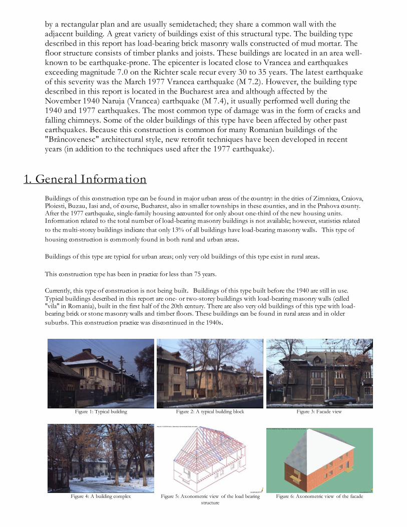
1. General InformationBuildings of this construction type can be found in major urban areas of the country: in the cities of Zimnicea, Craiova,Ploiesti, Buzau, Iasi and, of course, Bucharest, also in smaller townships in these counties, and in the Prahova county.After the 1977 earthquake, single-family housing accounted for only about one-third of the new housing units.Information related to the total number of load-bearing masonry buildings is not available; however, statistics relatedto the multi-storey buildings indicate that only 13% of all buildings have load-bearing masonry walls. This type ofhousing construction is commonly found in both rural and urban areas.
Buildings of this type are typical for urban areas; only very old buildings of this type exist in rural areas.
This construction type has been in practice for less than 75 years.
Currently, this type of construction is not being built. Buildings of this type built before the 1940 are still in use.Typical buildings described in this report are one- or two-storey buildings with load-bearing masonry walls (called"vila" in Romania), built in the first half of the 20th century. There are also very old buildings of this type with load-bearing brick or stone masonry walls and timber floors. These buildings can be found in rural areas and in oldersuburbs. This construction practice was discontinued in the 1940s.
Figure 1: Typical building
Figure 2: A typical building block
Figure 3: Facade view
Figure 4: A building complex
Figure 5: Axonometric view of the load bearingstructure
Figure 6: Axonometric view of the facade
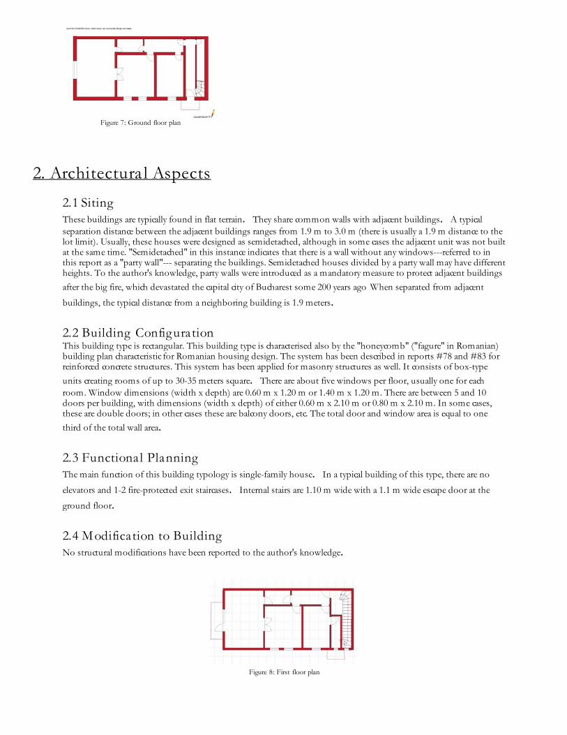
Figure 7: Ground floor plan
2. Architectura l Aspects
2.1 Siting These buildings are typically found in flat terrain. They share common walls with adjacent buildings. A typicalseparation distance between the adjacent buildings ranges from 1.9 m to 3.0 m (there is usually a 1.9 m distance to thelot limit). Usually, these houses were designed as semidetached, although in some cases the adjacent unit was not builtat the same time. "Semidetached" in this instance indicates that there is a wall without any windows---referred to inthis report as a "party wall"--- separating the buildings. Semidetached houses divided by a party wall may have differentheights. To the author's knowledge, party walls were introduced as a mandatory measure to protect adjacent buildingsafter the big fire, which devastated the capital city of Bucharest some 200 years ago When separated from adjacent
buildings, the typical distance from a neighboring building is 1.9 meters.
2.2 Building Configuration This building type is rectangular. This building type is characterised also by the "honeycomb" ("fagure" in Romanian)building plan characteristic for Romanian housing design. The system has been described in reports #78 and #83 forreinforced concrete structures. This system has been applied for masonry structures as well. It consists of box-typeunits creating rooms of up to 30-35 meters square. There are about five windows per floor, usually one for eachroom. Window dimensions (width x depth) are 0.60 m x 1.20 m or 1.40 m x 1.20 m. There are between 5 and 10doors per building, with dimensions (width x depth) of either 0.60 m x 2.10 m or 0.80 m x 2.10 m. In some cases,these are double doors; in other cases these are balcony doors, etc. The total door and window area is equal to onethird of the total wall area.
2.3 Functional Planning The main function of this building typology is single-family house. In a typical building of this type, there are no
elevators and 1-2 fire-protected exit staircases. Internal stairs are 1.10 m wide with a 1.1 m wide escape door at the
ground floor.
2.4 Modification to Building No structural modifications have been reported to the author's knowledge.
Figure 8: First floor plan
3. Structura l Deta ils
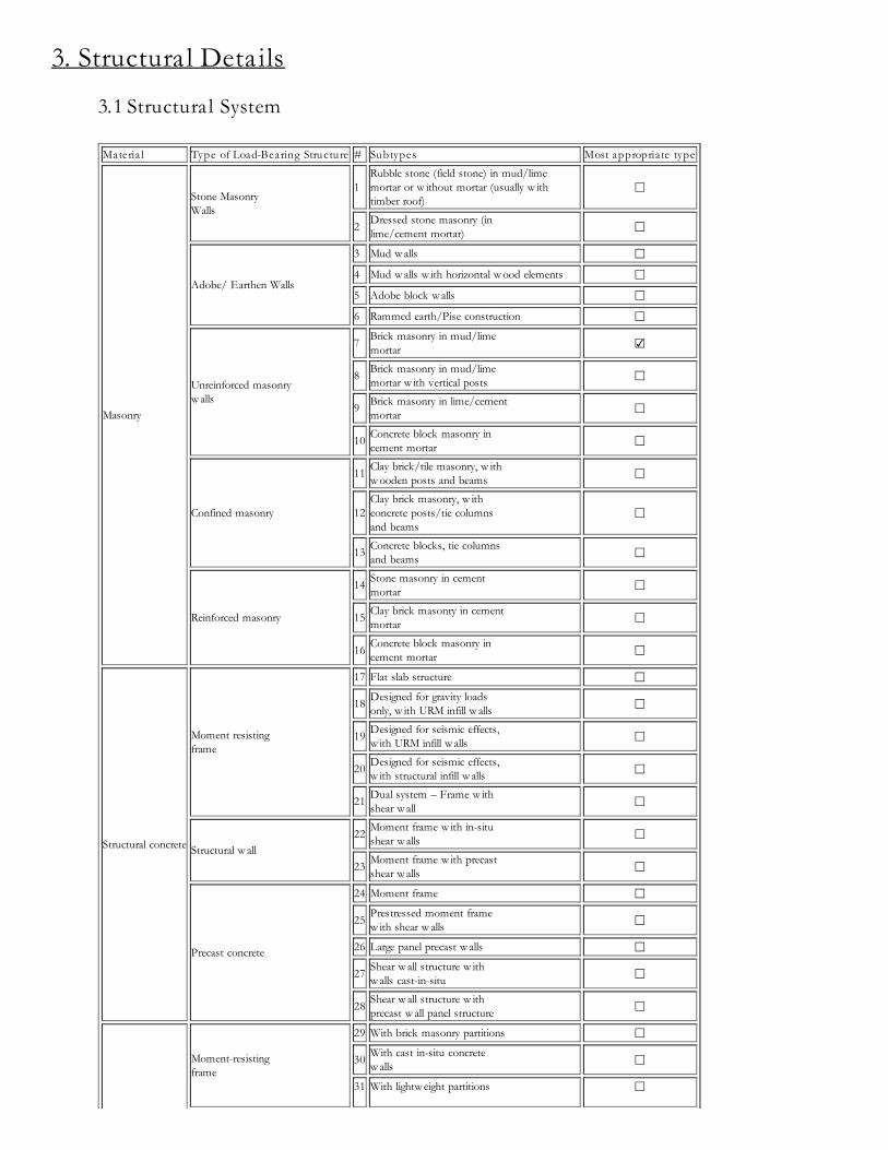
3.1 Structura l System Materia l Type of Load-Bearing Structure # Subtypes Most appropriate type
Masonry
Stone Masonry Walls
1Rubble stone (field stone) in mud/lime mortar or w ithout mortar (usually w ith timber roof)
☐
2 Dressed stone masonry (inlime/cement mortar) ☐
Adobe/ Earthen Walls
3 Mud w alls ☐4 Mud w alls w ith horizontal w ood elements ☐5 Adobe block w alls ☐6 Rammed earth/Pise construction ☐
Unreinforced masonryw alls
7 Brick masonry in mud/limemortar ☑
8 Brick masonry in mud/limemortar w ith vertical posts ☐
9 Brick masonry in lime/cementmortar ☐
10 Concrete block masonry incement mortar ☐
Confined masonry
11 Clay brick/tile masonry, w ithw ooden posts and beams ☐
12Clay brick masonry, w ithconcrete posts/tie columnsand beams
☐
13 Concrete blocks, tie columnsand beams ☐
Reinforced masonry
14 Stone masonry in cementmortar ☐
15 Clay brick masonry in cementmortar ☐
16 Concrete block masonry incement mortar ☐
Structural concrete
Moment resistingframe
17 Flat slab structure ☐18 Designed for gravity loads
only, w ith URM infill w alls ☐
19 Designed for seismic effects,w ith URM infill w alls ☐
20 Designed for seismic effects,w ith structural infill w alls ☐
21 Dual system – Frame w ithshear w all ☐
Structural w all22 Moment frame w ith in-situ
shear w alls ☐
23 Moment frame w ith precastshear w alls ☐
Precast concrete
24 Moment frame ☐25 Prestressed moment frame
w ith shear w alls ☐26 Large panel precast w alls ☐27 Shear w all structure w ith
w alls cast-in-situ ☐
28 Shear w all structure w ithprecast w all panel structure ☐
Moment-resistingframe
29 With brick masonry partitions ☐30 With cast in-situ concrete
w alls ☐31 With lightw eight partitions ☐
Steel
Braced frame
32 Concentric connections in allpanels ☐
33 Eccentric connections in afew panels ☐
Structural w all34 Bolted plate ☐35 Welded plate ☐
Timber Load-bearing timberframe
36 Thatch ☐37 Walls w ith bamboo/reed mesh
and post (Wattle and Daub) ☐
38Masonry w ith horizontalbeams/planks at intermediatelevels
☐
39 Post and beam frame (nospecial connections) ☐
40 Wood frame (w ith specialconnections) ☐
41Stud-w all frame w ithplyw ood/gypsum boardsheathing
☐
42 Wooden panel w alls ☐
OtherSeismic protection systems
43 Building protected w ith base-isolation systems ☐44 Building protected w ith
seismic dampers ☐Hybrid systems 45 other (described below ) ☐
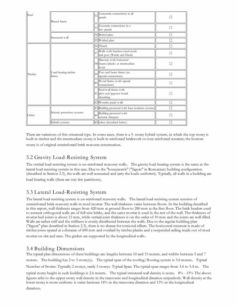
There are variations of this structural type. In some cases, there is a 3- storey hybrid system, in which the top storey isbuilt in timber and the intermediate storey is built in reinforced brickwork or even reinforced concrete; the bottomstorey is of original unreinforced brick masonry construction.
3.2 Gravity Load-Resisting System The vertical load-resisting system is un-reinforced masonry walls. The gravity load-bearing system is the same as thelateral load-resisting system in this case. Due to the "honeycomb" ("fagure" in Romanian) building configuration(described in Section 2.3), the walls are well connected and carry the loads uniformly. Typically, all walls in a building areload-bearing walls (there are very few partitions).
3.3 Latera l Load-Resisting System The lateral load-resisting system is un-reinforced masonry walls. The lateral load-resisting system consists ofunreinforced brick masonry walls in mud mortar. The wall thickness varies between floors. In the building describedin this report, wall thickness ranges from 420 mm at ground floor to 280 mm at the first floor. The brick headers usedto connect orthogonal walls are of full-size bricks, and the same mortar is used in the rest of the wall. The thickness ofmortar bed joints is about 12 mm, while vertical joint thickness is on the order of 10 mm and the joints are well-filled.Walls are rather stiff and the stiffness is evenly distributed between the walls. Due to the regular building plan("fagure" plan described in Section 2.3), there is no chance for torsional effects. The horizontal structure is made oftimber joists spaced at a distance of 600 mm and overlaid by timber planks and a suspended ceiling made out of mudmortar on slat and cane. The girders are supported by the longitudinal walls.
3.4 Building Dimensions The typical plan dimensions of these buildings are: lengths between 10 and 15 meters, and widths between 5 and 7meters. The building has 2 to 3 storey(s). The typical span of the roofing/flooring system is 3.6 meters. Typical
Number of Stories: Typically 2 storeys, rarely 3 storeys. Typical Span: The typical span ranges from 3.6 to 5.4 m. The
typical storey height in such buildings is 2.6 meters. The typical structural wall density is none. 8% - 15% The abovefigures refer to the upper storey wall density in the transverse and longitudinal direction respectively. Wall density at thelower storey is more uniform: it varies between 14% in the transverse direction and 13% in the longitudinaldirection.

3.5 Floor and Roof System
Materia l Description of floor/roof system Most appropriate floor Most appropriate roof
MasonryVaulted ☐ ☐Composite system of concrete joists andmasonry panels ☐ ☐
Structural concrete
Solid slabs (cast-in-place) ☐ ☐Waffle slabs (cast-in-place) ☐ ☐Flat slabs (cast-in-place) ☐ ☐Precast joist system ☐ ☐Hollow core slab (precast) ☐ ☐Solid slabs (precast) ☐ ☐Beams and planks (precast) w ith concretetopping (cast-in-situ) ☐ ☐Slabs (post-tensioned) ☐ ☐
Steel Composite steel deck w ith concrete slab(cast-in-situ) ☐ ☐
Timber
Rammed earth w ith ballast and concrete orplaster finishing ☐ ☐Wood planks or beams w ith ballast and concrete or plaster finishing ☐ ☐Thatched roof supported on w ood purlins ☐ ☐Wood shingle roof ☐ ☐Wood planks or beams that support clay tiles ☐Wood planks or beams supporting naturalstones slates ☐ ☐Wood planks or beams that support slate,metal, asbestos-cement or plastic corrugatedsheets or tiles
☐ ☐
Wood plank, plyw ood or manufactured w oodpanels on joists supported by beams or w alls ☑ ☐
Other Described below ☑ ☑
3.6 Foundation
Type Description Most appropriate type
Shallow foundation
Wall or column embedded insoil, w ithout footing ☐Rubble stone, fieldstoneisolated footing ☐Rubble stone, fieldstone stripfooting ☐Reinforced-concrete isolatedfooting ☐Reinforced-concrete stripfooting ☐Mat foundation ☐No foundation ☐
Deep foundation
Reinforced-concrete bearingpiles ☐Reinforced-concrete skinfriction piles ☐Steel bearing piles ☐Steel skin friction piles ☐
Wood piles ☐Cast-in-place concrete piers ☐Caissons ☐
Other Described below ☐
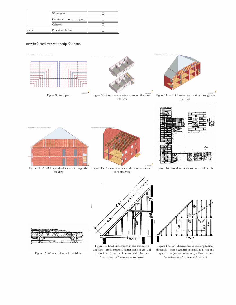
unreinforced concrete strip footing.
Figure 9: Roof plan
Figure 10: Axonometric view - ground floor andfirst floor
Figure 11: A 3D longitudinal section through thebuilding
Figure 11: A 3D longitudinal section through thebuilding
Figure 13: Axonometric view show ing w alls andfloor structure
Figure 14: Wooden floor - sections and details
Figure 15: Wooden floor w ith finishing
Figure 16: Roof dimensions in the transversedirection - cross-sectional dimensions in cm and
spans in m (source unknow n, addendum to"Constructions" course, in German)
Figure 17: Roof dimensions in the longitudinaldirection - cross-sectional dimensions in cm and
spans in m (source unknow n, addendum to"Constructions" course, in German)
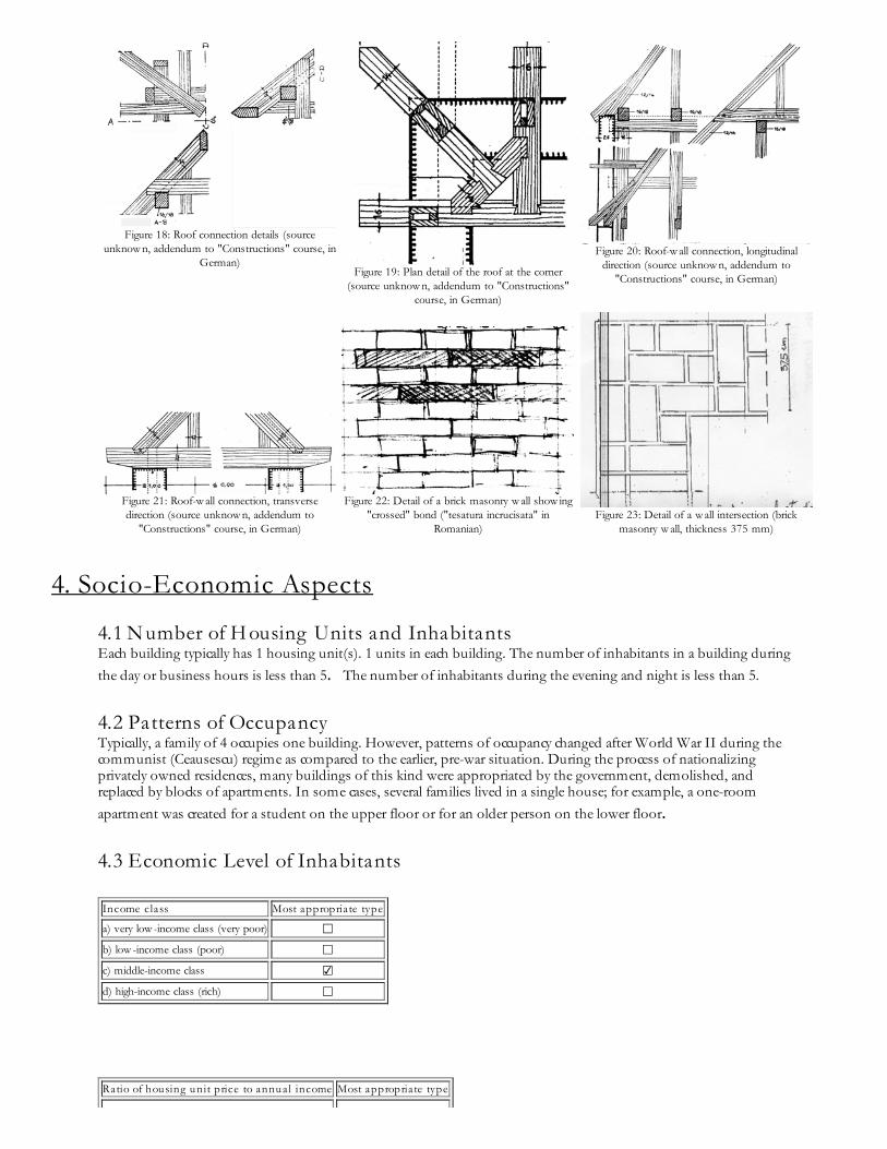
Figure 18: Roof connection details (sourceunknow n, addendum to "Constructions" course, in
German)Figure 19: Plan detail of the roof at the corner
(source unknow n, addendum to "Constructions"course, in German)
Figure 20: Roof-w all connection, longitudinaldirection (source unknow n, addendum to
"Constructions" course, in German)
Figure 21: Roof-w all connection, transversedirection (source unknow n, addendum to
"Constructions" course, in German)
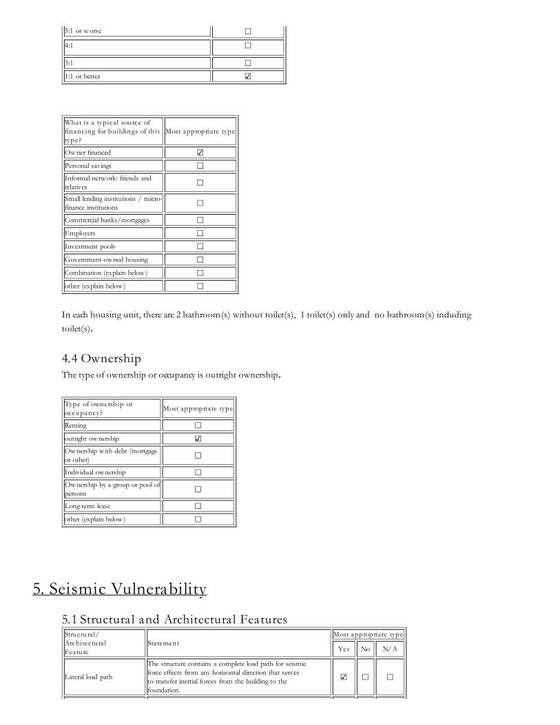
Figure 22: Detail of a brick masonry w all show ing"crossed" bond ("tesatura incrucisata" in
Romanian)Figure 23: Detail of a w all intersection (brick
masonry w all, thickness 375 mm)
4. Socio-Economic Aspects
4.1 Number of H ousing Units and Inhabitants Each building typically has 1 housing unit(s). 1 units in each building. The number of inhabitants in a building duringthe day or business hours is less than 5. The number of inhabitants during the evening and night is less than 5.
4.2 Patterns of Occupancy Typically, a family of 4 occupies one building. However, patterns of occupancy changed after World War II during thecommunist (Ceausescu) regime as compared to the earlier, pre-war situation. During the process of nationalizingprivately owned residences, many buildings of this kind were appropriated by the government, demolished, andreplaced by blocks of apartments. In some cases, several families lived in a single house; for example, a one-roomapartment was created for a student on the upper floor or for an older person on the lower floor.
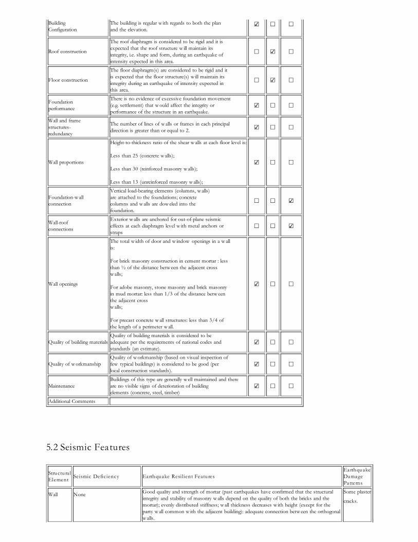
4.3 Economic Level of Inhabitants
Income class Most appropriate type
a) very low -income class (very poor) ☐b) low -income class (poor) ☐c) middle-income class ☑d) high-income class (rich) ☐
Ratio of housing unit price to annual income Most appropriate type
5:1 or w orse ☐4:1 ☐
3:1 ☐1:1 or better ☑
What is a typica l source offinancing for bu ildings of thistype?
Most appropriate type
Ow ner financed ☑Personal savings ☐Informal netw ork: friends andrelatives ☐Small lending institutions / micro-finance institutions ☐Commercial banks/mortgages ☐Employers ☐Investment pools ☐Government-ow ned housing ☐Combination (explain below ) ☐other (explain below ) ☐
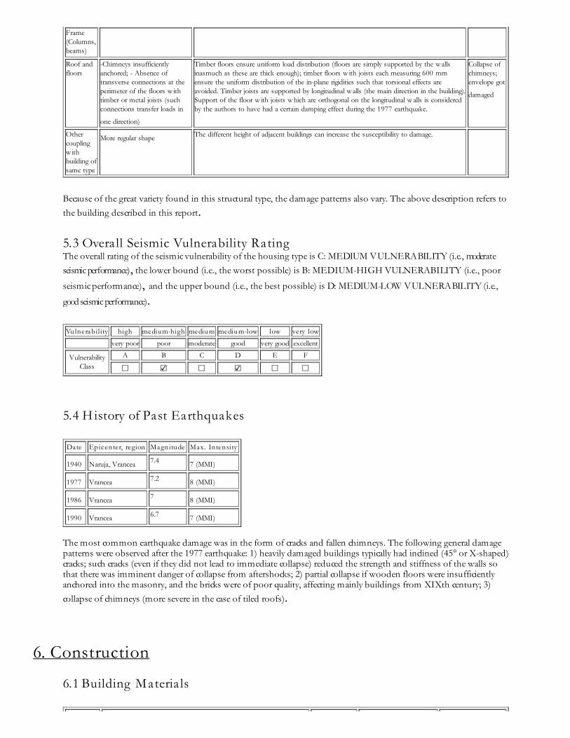
In each housing unit, there are 2 bathroom(s) without toilet(s), 1 toilet(s) only and no bathroom(s) includingtoilet(s).
4.4 Ownership The type of ownership or occupancy is outright ownership.
Type of ownership oroccupancy? Most appropriate type
Renting ☐outright ow nership ☑Ow nership w ith debt (mortgageor other) ☐Individual ow nership ☐Ow nership by a group or pool ofpersons ☐Long-term lease ☐other (explain below ) ☐
5. Seismic Vulnerability
5.1 Structura l and Architectura l Features Structura l/Architectura lFeature
StatementMost appropriate type
Yes No N/A
Lateral load path
The structure contains a complete load path for seismicforce effects from any horizontal direction that servesto transfer inertial forces from the building to thefoundation.
☑ ☐ ☐
BuildingConfiguration
The building is regular w ith regards to both the planand the elevation.
☑ ☐ ☐
Roof construction
The roof diaphragm is considered to be rigid and it isexpected that the roof structure w ill maintain itsintegrity, i.e. shape and form, during an earthquake ofintensity expected in this area.
☐ ☑ ☐
Floor construction
The floor diaphragm(s) are considered to be rigid and itis expected that the floor structure(s) w ill maintain itsintegrity during an earthquake of intensity expected inthis area.
☐ ☑ ☐
Foundationperformance
There is no evidence of excessive foundation movement(e.g. settlement) that w ould affect the integrity orperformance of the structure in an earthquake.
☑ ☐ ☐
Wall and framestructures-redundancy
The number of lines of w alls or frames in each principaldirection is greater than or equal to 2. ☑ ☐ ☐
Wall proportions
Height-to-thickness ratio of the shear w alls at each floor level is:
Less than 25 (concrete w alls);
Less than 30 (reinforced masonry w alls);
Less than 13 (unreinforced masonry w alls);
☑ ☐ ☐
Foundation-w allconnection
Vertical load-bearing elements (columns, w alls)are attached to the foundations; concretecolumns and w alls are dow eled into thefoundation.
☐ ☐ ☑
Wall-roofconnections
Exterior w alls are anchored for out-of-plane seismiceffects at each diaphragm level w ith metal anchors orstraps
☐ ☐ ☑
Wall openings
The total w idth of door and w indow openings in a w allis:
For brick masonry construction in cement mortar : lessthan ½ of the distance betw een the adjacent crossw alls;
For adobe masonry, stone masonry and brick masonryin mud mortar: less than 1/3 of the distance betw eenthe adjacent crossw alls;
For precast concrete w all structures: less than 3/4 ofthe length of a perimeter w all.
☑ ☐ ☐
Quality of building materialsQuality of building materials is considered to beadequate per the requirements of national codes andstandards (an estimate).
☑ ☐ ☐
Quality of w orkmanshipQuality of w orkmanship (based on visual inspection offew typical buildings) is considered to be good (perlocal construction standards).
☑ ☐ ☐
MaintenanceBuildings of this type are generally w ell maintained and thereare no visible signs of deterioration of buildingelements (concrete, steel, timber)
☑ ☐ ☐
Additional Comments
5.2 Seismic Features Structura lElement Seismic Deficiency Earthquake Resilient Features
EarthquakeDamagePatterns
Wall None Good quality and strength of mortar (past earthquakes have confirmed that the structuralintegrity and stability of masonry w alls depend on the quality of both the bricks and themortar); evenly distributed stiffness; w all thickness decreases w ith height (except for theparty w all common w ith the adjacent building): adequate connection betw een the orthogonalw alls.
Some plaster
cracks.
Frame(Columns,beams)
Roof andfloors
-Chimneys insufficientlyanchored; - Absence oftransverse connections at theperimeter of the floors w ithtimber or metal joists (suchconnections transfer loads in
one direction)
Timber floors ensure uniform load distribution (floors are simply supported by the w allsinasmuch as these are thick enough); timber floors w ith joists each measuring 600 mmensure the uniform distribution of the in-plane rigidities such that torsional effects areavoided. Timber joists are supported by longitudinal w alls (the main direction in the building).Support of the floor w ith joists w hich are orthogonal on the longitudinal w alls is consideredby the authors to have had a certain damping effect during the 1977 earthquake.
Collapse ofchimneys;envelope got
damaged
Othercouplingw ithbuilding ofsame type
More regular shape The different height of adjacent buildings can increase the susceptibility to damage.
Because of the great variety found in this structural type, the damage patterns also vary. The above description refers tothe building described in this report.
5.3 Overall Seismic Vulnerability Rating The overall rating of the seismic vulnerability of the housing type is C: MEDIUM VULNERABILITY (i.e., moderateseismic performance), the lower bound (i.e., the worst possible) is B: MEDIUM-HIGH VULNERABILITY (i.e., poor
seismic performance), and the upper bound (i.e., the best possible) is D: MEDIUM-LOW VULNERABILITY (i.e.,
good seismic performance).
Vulnerability high medium-high medium medium-low low very low
very poor poor moderate good very good excellent
VulnerabilityClass
A B C D E F
☐ ☑ ☐ ☑ ☐ ☐
5.4 H istory of Past Earthquakes Date Epicenter, region Magnitude Max. Intensity
1940 Naruja, Vrancea 7.4 7 (MMI) 1977 Vrancea 7.2 8 (MMI) 1986 Vrancea 7 8 (MMI) 1990 Vrancea 6.7 7 (MMI)
The most common earthquake damage was in the form of cracks and fallen chimneys. The following general damagepatterns were observed after the 1977 earthquake: 1) heavily damaged buildings typically had inclined (45° or X-shaped)cracks; such cracks (even if they did not lead to immediate collapse) reduced the strength and stiffness of the walls sothat there was imminent danger of collapse from aftershocks; 2) partial collapse if wooden floors were insufficientlyanchored into the masonry, and the bricks were of poor quality, affecting mainly buildings from XIXth century; 3)collapse of chimneys (more severe in the case of tiled roofs).
6. Construction
6.1 Building Materia ls
Structura lelement
Bu ilding materia l Characteristicstrength
Mixproportions/dimensions
Comments
Walls Bricks 6.25cmx12.5cmx25cm
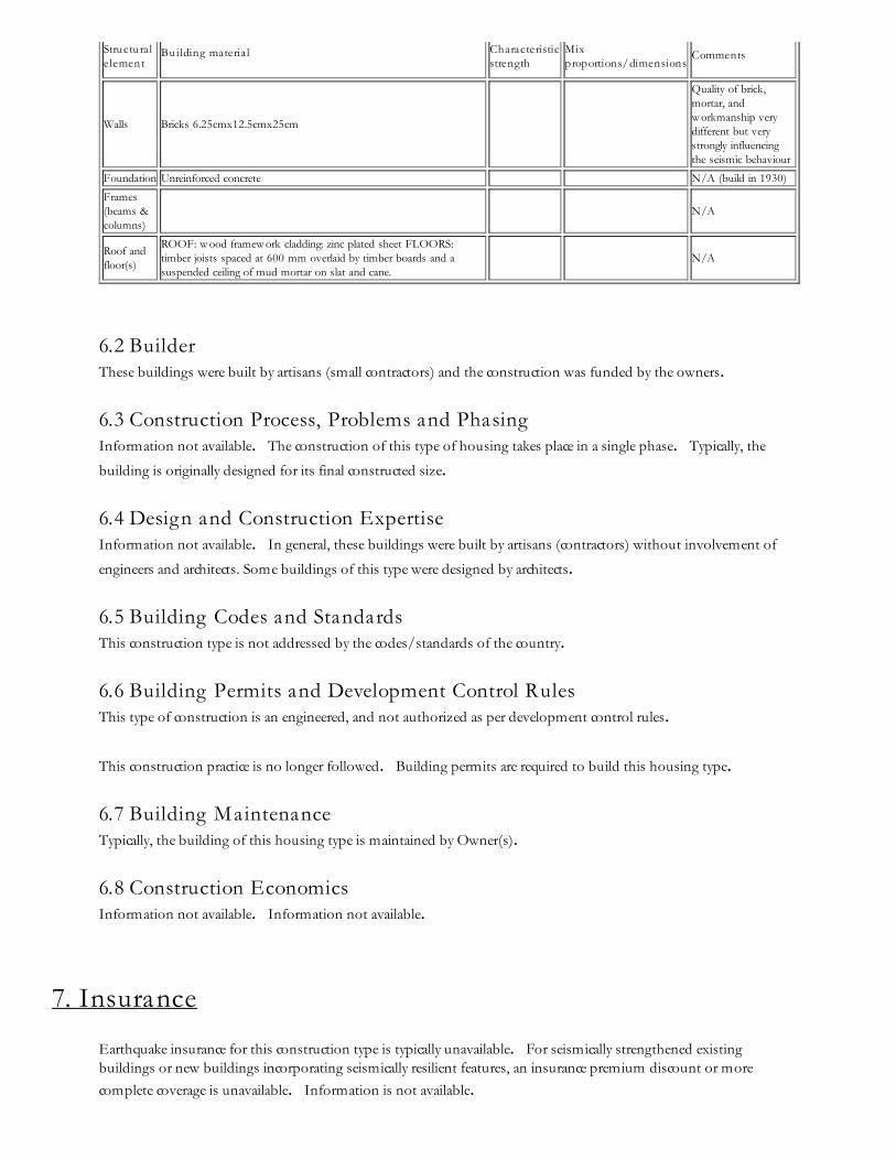
Quality of brick,mortar, andw orkmanship verydifferent but verystrongly influencingthe seismic behaviour
Foundation Unreinforced concrete N/A (build in 1930)
Frames(beams &columns)
N/A
Roof andfloor(s)
ROOF: w ood framew ork cladding: zinc plated sheet FLOORS:timber joists spaced at 600 mm overlaid by timber boards and asuspended ceiling of mud mortar on slat and cane.
N/A
6.2 Builder These buildings were built by artisans (small contractors) and the construction was funded by the owners.
6.3 Construction Process, Problems and Phasing Information not available. The construction of this type of housing takes place in a single phase. Typically, the
building is originally designed for its final constructed size.
6.4 Design and Construction Expertise Information not available. In general, these buildings were built by artisans (contractors) without involvement of
engineers and architects. Some buildings of this type were designed by architects.
6.5 Building Codes and Standards This construction type is not addressed by the codes/standards of the country.
6.6 Building Permits and Development Control Rules This type of construction is an engineered, and not authorized as per development control rules.
This construction practice is no longer followed. Building permits are required to build this housing type.
6.7 Building Maintenance Typically, the building of this housing type is maintained by Owner(s).
6.8 Construction Economics Information not available. Information not available.
7. Insurance
Earthquake insurance for this construction type is typically unavailable. For seismically strengthened existingbuildings or new buildings incorporating seismically resilient features, an insurance premium discount or morecomplete coverage is unavailable. Information is not available.
8. Strengthening
8.1 Description of Seismic Strengthening Provisions
Strengthening of Existing Construction :SeismicDeficiency Description of Seismic Strengthening provisions used
Diagonal "X"cracks in the
w alls
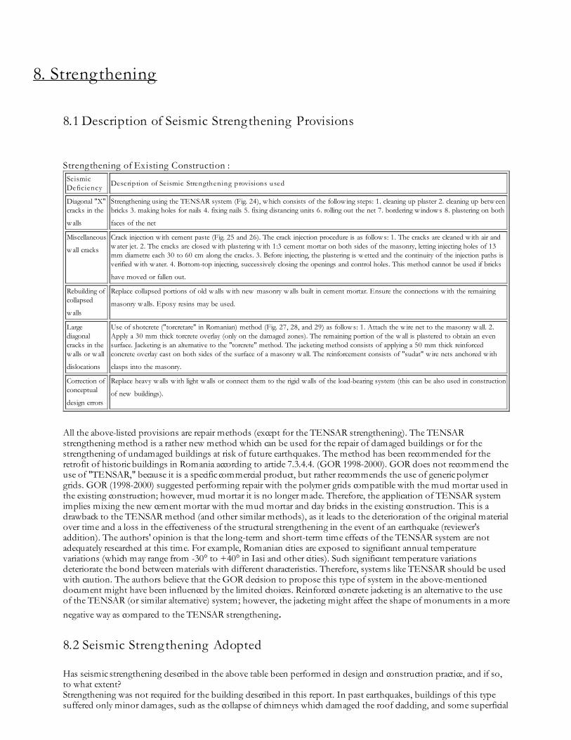
Strengthening using the TENSAR system (Fig. 24), w hich consists of the follow ing steps: 1. cleaning up plaster 2. cleaning up betw eenbricks 3. making holes for nails 4. fixing nails 5. fixing distancing units 6. rolling out the net 7. bordering w indow s 8. plastering on both
faces of the net Miscellaneous
w all cracks Crack injection w ith cement paste (Fig. 25 and 26). The crack injection procedure is as follow s: 1. The cracks are cleaned w ith air andw ater jet. 2. The cracks are closed w ith plastering w ith 1:3 cement mortar on both sides of the masonry, letting injecting holes of 13mm diametre each 30 to 60 cm along the cracks. 3. Before injecting, the plastering is w etted and the continuity of the injection paths isverified w ith w ater. 4. Bottom-top injecting, successively closing the openings and control holes. This method cannot be used if bricks
have moved or fallen out. Rebuilding ofcollapsed
w alls
Replace collapsed portions of old w alls w ith new masonry w alls built in cement mortar. Ensure the connections w ith the remaining
masonry w alls. Epoxy resins may be used.
Largediagonalcracks in thew alls or w all
dislocations
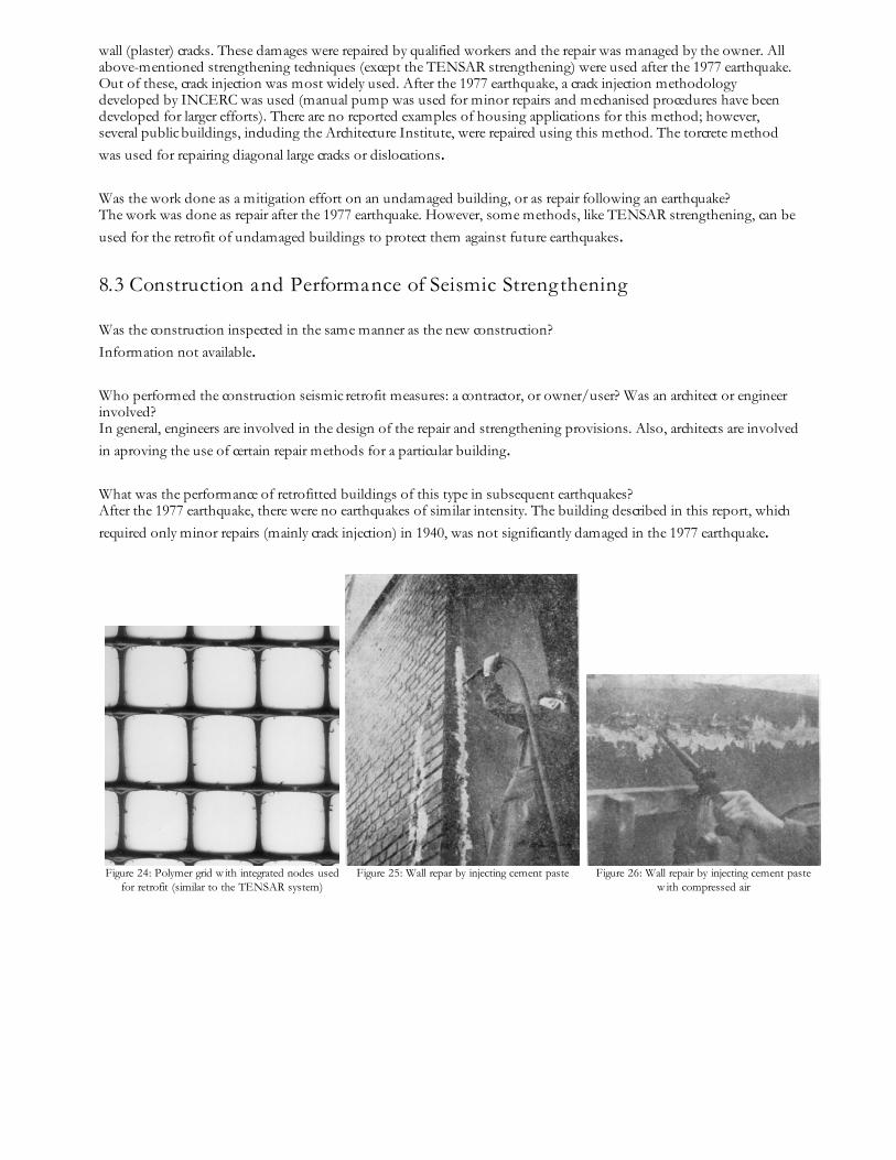
Use of shotcrete ("torcretare" in Romanian) method (Fig. 27, 28, and 29) as follow s: 1. Attach the w ire net to the masonry w all. 2.Apply a 30 mm thick torcrete overlay (only on the damaged zones). The remaining portion of the w all is plastered to obtain an evensurface. Jacketing is an alternative to the "torcrete" method. The jacketing method consists of applying a 50 mm thick reinforcedconcrete overlay cast on both sides of the surface of a masonry w all. The reinforcement consists of "sudat" w ire nets anchored w ith
clasps into the masonry. Correction ofconceptual
design errors
Replace heavy w alls w ith light w alls or connect them to the rigid w alls of the load-bearing system (this can be also used in construction
of new buildings).
All the above-listed provisions are repair methods (except for the TENSAR strengthening). The TENSARstrengthening method is a rather new method which can be used for the repair of damaged buildings or for thestrengthening of undamaged buildings at risk of future earthquakes. The method has been recommended for theretrofit of historic buildings in Romania according to article 7.3.4.4. (GOR 1998-2000). GOR does not recommend theuse of "TENSAR," because it is a specific commercial product, but rather recommends the use of generic polymergrids. GOR (1998-2000) suggested performing repair with the polymer grids compatible with the mud mortar used inthe existing construction; however, mud mortar it is no longer made. Therefore, the application of TENSAR systemimplies mixing the new cement mortar with the mud mortar and clay bricks in the existing construction. This is adrawback to the TENSAR method (and other similar methods), as it leads to the deterioration of the original materialover time and a loss in the effectiveness of the structural strengthening in the event of an earthquake (reviewer'saddition). The authors' opinion is that the long-term and short-term time effects of the TENSAR system are notadequately researched at this time. For example, Romanian cities are exposed to significant annual temperaturevariations (which may range from -30° to +40° in Iasi and other cities). Such significant temperature variationsdeteriorate the bond between materials with different characteristics. Therefore, systems like TENSAR should be usedwith caution. The authors believe that the GOR decision to propose this type of system in the above-mentioneddocument might have been influenced by the limited choices. Reinforced concrete jacketing is an alternative to the useof the TENSAR (or similar alternative) system; however, the jacketing might affect the shape of monuments in a morenegative way as compared to the TENSAR strengthening.
8.2 Seismic Strengthening Adopted
Has seismic strengthening described in the above table been performed in design and construction practice, and if so,to what extent? Strengthening was not required for the building described in this report. In past earthquakes, buildings of this typesuffered only minor damages, such as the collapse of chimneys which damaged the roof cladding, and some superficial
wall (plaster) cracks. These damages were repaired by qualified workers and the repair was managed by the owner. Allabove-mentioned strengthening techniques (except the TENSAR strengthening) were used after the 1977 earthquake.Out of these, crack injection was most widely used. After the 1977 earthquake, a crack injection methodologydeveloped by INCERC was used (manual pump was used for minor repairs and mechanised procedures have beendeveloped for larger efforts). There are no reported examples of housing applications for this method; however,several public buildings, including the Architecture Institute, were repaired using this method. The torcrete methodwas used for repairing diagonal large cracks or dislocations.
Was the work done as a mitigation effort on an undamaged building, or as repair following an earthquake? The work was done as repair after the 1977 earthquake. However, some methods, like TENSAR strengthening, can beused for the retrofit of undamaged buildings to protect them against future earthquakes.
8.3 Construction and Performance of Seismic Strengthening
Was the construction inspected in the same manner as the new construction? Information not available.
Who performed the construction seismic retrofit measures: a contractor, or owner/user? Was an architect or engineerinvolved? In general, engineers are involved in the design of the repair and strengthening provisions. Also, architects are involvedin aproving the use of certain repair methods for a particular building.
What was the performance of retrofitted buildings of this type in subsequent earthquakes? After the 1977 earthquake, there were no earthquakes of similar intensity. The building described in this report, whichrequired only minor repairs (mainly crack injection) in 1940, was not significantly damaged in the 1977 earthquake.
Figure 24: Polymer grid w ith integrated nodes usedfor retrofit (similar to the TENSAR system)
Figure 25: Wall repar by injecting cement paste
Figure 26: Wall repair by injecting cement pastew ith compressed air
Figure 27: "Torcrete" retrofit method
Figure 28: Torcrete method - step 1: cleaning ofthe w all surface w ith compressed air
Figuer 29: "Torcrete" retrofit : application oftorcrete overlay on the steel net attached to the
w all
Reference(s)1. Cutremurul de Pam
Balan,S., Cristescu,V., and Cornea,I.The Academy of the Socialist Republic of Romania, Bucharest, Romania 1982
2. Recommendations over the retrofit of buildings after an earthquake (in Greek)TEEEdited by the Association of Greek Engineers (TEE), Rectorat of the National Technical University of Athens, Athens, Greece 1988
3. Sto Ges.m.b.H., Austria http://www.sto.at/htmger/servi_f.htmSTO
4. ConstructionsSmighielschi,M.Course Notes (in Romanian), Institute of Architecture Ion Mincu, Bucharest, Romania
5. Stan. FinishingsCourse Notes (in Romanian), Institute of Architecture Ion Mincu, Bucharest, Romania
6. Methodology for the Risk Evaluation and Required Restoration Interventions for the Historical MonumentStructuresGORIntermediary Manuscript, Phase 4 (1998-2000), the Romanian Ministry for Public Works and Regional Planing, Government of Romania,Bucharest, Romania 2000
7. Strengthening and/or rehabilitation of clay brick masonry buildings with polymer grids with integrated stiffnodesAGIRCourse proceedings, The Romanian Engineering Association (AGIR), Bucharest, Romania 2002
8. RichterGard. http://www.richtergard.com/home2.html
9. ConstructionCourse notes-an addendum (in German). Institute of Architecture "Ion Mincu"; Bucharest, Romania
Author(s)1. Maria D. Bostenaru
researcher, History and Theory of Architecture & Heritage Cons, Ion Mincu University of Architecture and Urbanism
str. Academiei nr. 18-20, Bucharest 010014, ROMANIAEmail:[email protected] FAX: 0040213077178
2. Ilie Sandu, Sos. Oltenitei 34Bl. 5C et. V ap. 23, Bucharest 7000, ROMANIA
Reviewer(s)1. Dina D'Ayala
Director of Postgraduate StudiesDepartment of Architecture & Civil Engineering, University of BathBath BA2 7AY, UNITED KINGDOMEmail:D.F.D'[email protected] FAX: 00 44 1225 386691
Save page as