Embed Size (px)
Citation preview
HOUSELIGHT HOIST Lighting Suspension
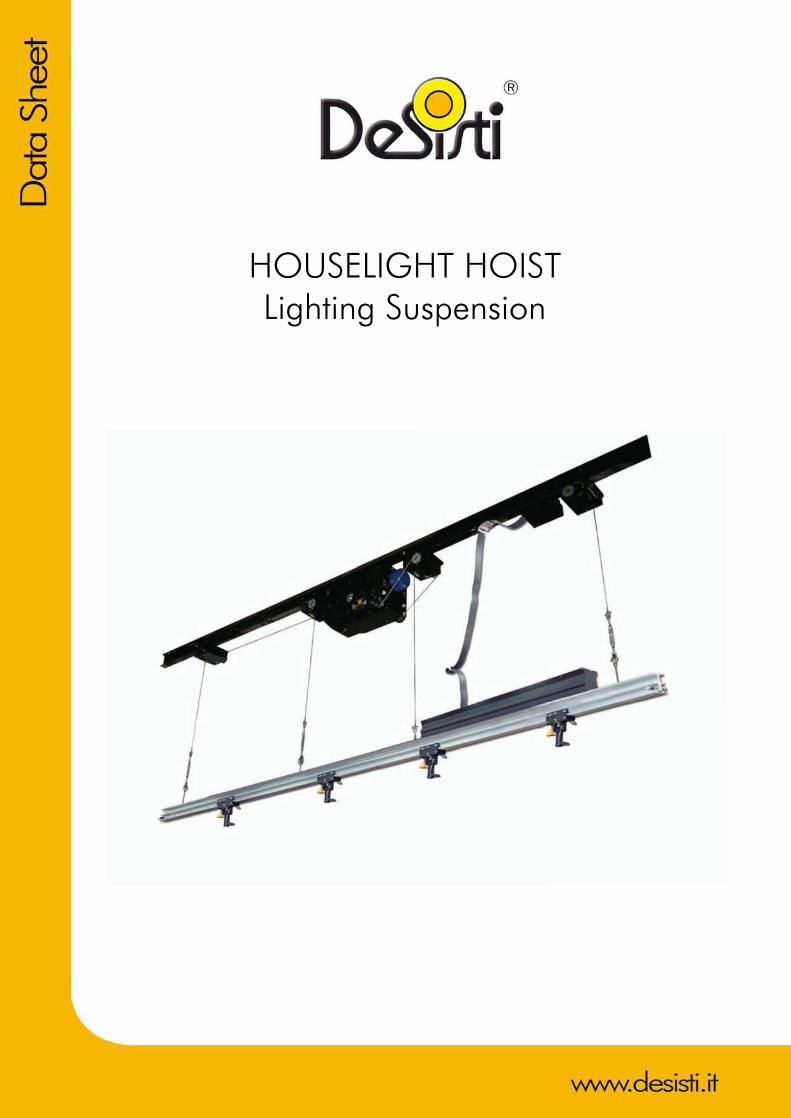
FEATURES • SAFETY The HOUSELIGHT HOIST complies with all safety standards set forth by the Internationally
recognized testing authorities of VBG 70 and by UL laboratories standards. These standards are directly associated with the safety of suspensions systems mounted above an assembly of people. The safety features incorporated into the HOUSELIGHT HOIST include, a self sustaining worm-geared set motor to prevent back winding in a static position and backed up by a breaking system when moving. The system also includes two safety micro switches, one for the top limit plus an extra emergency safety switch and one for the bottom limit plus an extra emergency safety switch. Each wire rope has overload sensors and slack line detection.
• FLEXIBILITY The HOUSELIGHT HOIST can be specified in lengths from 30’ (9.1 meters) up to 60’ (18 meters) and can carry loads up to 200 lbs evenly distributed SWL (Safe Working Load). The HOUSELIGHT HOIST can provide up to 60’ of an extruded aluminum I beam which acts as a combination wire-way and mounting rail for architectural lighting fixtures. The flexibility, ease of installation, and the length of the mounting rail it can lift, makes it an ideal product for accessing the houselights. This is especially true where no other access for servicing and re-lamping the auditorium down lights exists.
• MECHANICAL The mechanical design incorporates Three major components. The First is a motor compartment which is under hung from the steel and houses a 1.8kw motor, dual cable lifting drums, the 3 Phase 208 volt power feed terminals and the control circuit terminals. The Second, depending on the length of the batten, which can be up to 60 feet long, will incorporate either two or four single line diverter pulley’s modules. Sheet metal strips shall be mounted between the motor module and each pulley separating the modules and provides for exact spacing. The diverter pulley modules will support the length of the Pipe Batten with single lift cables. Each Cable having a minimum breaking load of 1,200 kg / 2,400 lbs. The third component is an extruded aluminum I Beam (for rigidity over the 60’ span) wire way with a cover on the front and back. A strain relief for the lighting fixture cord is mounted into holes punched into the wire way cover. The wire way houses the outlet terminal blocks for hardwiring the lighting fixtures and can also be barricaded in order to separate any emergency lighting circuits. The main components are all pre-wired and pre-assembled from the factory making the installation an easy task.

• OPERATIONAL The HOUSELIGHT HOIST is capable of lifting a (SWL) safe working load of 200 lbs, plus the self-weight of the hoist, which is based on the travel distance and the optional features included. The maximum travel distance is 40 feet / 12 meters. Special travel distance requirements are available as an option.
• OPTIONAL FEATURES The De Sisti HOUSELIGHT HOIST offers several unique optional features: 1. Memorized Posi t ioning Control memorizes and recalls the position of each hoist and
records the information into a preset. 2. DMX Up/Down and Posi t ioning Control via a standard lighting control board or any
DMX control system
SPECIFICATIONS The De Sisti Rigging and Automation HOUSELIGHT HOIST shall be made up of THREE elements. The first being the motor module compartment which shall be a completely self-contained enclosure. This enclosure shall house a motorized winch drive unit with dual cable lifting drums, limit and load sensing switches and terminals for both the motor feed and control terminals. The Second, depending on the length of the mounting rail, (which can be up to 60 feet in length) shall incorporate either two or four single line diverter pulley modules. The Third is an aluminum I-Beam / Wire way which carries the load circuits (up to 6 – 20amp circuits) to terminal blocks spaced to accommodate the architectural down lights along the length of the wire way. Sheet metal strips and a terminal box mounting rail shall be mounted between the motor module and each of the diverter pulley module to separate the modules and providing for exact spacing. The diverter pulley modules shall support the entire length of the extruded aluminum I- Beam Mounting Rail with single line wire rope lifting cables. Each wire rope lifting cable shall have a minimum breaking load of 1,200 kg / 2,400 lbs. The main components shall all be pre-wired and pre-assembled from the factory making the installation an easy task. This product shall be U.L. approved as a complete system. Other products that incorporate a combination of U.L. components, but not specifically approved and tested by U.L. as a complete working system will not be accepted. The motor assembly shall house a 1.8kw 208 volt, 60 Hz 3-phase motor, integrated with a sel f sustaining worm-geared set to prevent back winding in a static position and backed up by a breaking system when the hoist is moving. The maximum torque shall be either 616Nm or 1,000Nm, with permanent lubrication. The average lifting speed shall be 30 feet per minute. The SWL (safe working load) shall be 200 lbs, distributed evenly over the length of the mounting rail. The maximum travel distance is 40’ (12 meters). It shall have four independent steel lifting cables 4mm.in diameter, constructed in 7 groups of 19 wires with a minimum breaking force on each wire rope of at least 1,200 kg / 2,400 lbs. Incorporated into the hoist system shall be cut out safety micro switches (double act ivated SPRING-LEVER type) for each cable l ine for both slack line and overload detection, plus travel limit switches, one for the top plus extra safety switch and one bottom limit switch plus safety stop switch. All circuit protection panel boards, emergency contactors, three phase feed to the motors, control wiring and load circuit wiring to the hoist shall be by others unless otherwise specified. The entire device must comply with all the safety standards as set forth by the Internationally recognized testing authorized VBG 70 and carry the U.L. label Tested and Approved as a complete system. There are several Control Options offered by De Sisti.
• Up /Down Push Button Control either PBS (Push Button Station) or HMC (Hoist Manual Control with optional remote control).
• DMX Up / Down Control as well as Positioning Control. • HDC System (Hoist Digital Control) with manual back up DMX Input. • ICARUS Control System for (Memory Control of hoists and automated lighting)
FCT FOLDING CABLE TRAY version
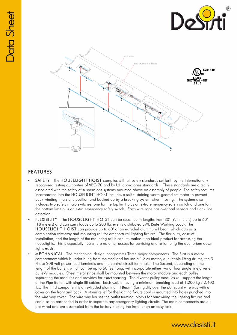
CHARACTERISTICS & PERFORMANCE DATA
STANDARD DUTY VERSION
Total l i f t ing capacity of winch unit:
416 kg / 915 lbs.
Net l i f t ing capacity of HOIST (PAYLOAD):
In this product the net Capacity is limited to 200 lbs to permit a lightweight and long moving batten. Safe Working Load is 91 kg. / 200 lbs. (distributed load)
Number of l i f t cables: 4 independent steel ropes
Li f t cable specif icat ions: 4 mm. diameter, 7 x 19 construction, galvanized steel wire ropes, specific resistance class 200 kg.: sq.mm. UNI 7293-74. Minimum breaking Load 1,200 kg / 2,400 lbs
Li f t ing speed (average): 9 m/min. – 30’/min.
Winch Unit specs for Vert ical l i f t :
1.8 kW, 3 phase AC primary supply: 120/208 V 60 Hz +/- 5 %, Transmission ratio 1:60
Load Sensing: Over/under load sensing mechanism independent on each lift cable
Travel l imit system TÜV approved mechanism, including 4 fine adjustable safety switches (resolution of 3 mm. in a 10.5 m. travel), including: ET = EXTRA TOP LIMIT, TL = TOP LIMIT, BL = BOTTOM
LIMIT, EB = EXTRA BOTTOM LIMIT. The mechanism can be easily retrofitted with positioning sensor.
TYPICAL HOUSELIGHT HOIST DRAWING
HOUSELIGHT HOIST
BATTEN HOIST
STAGE HOIST

TYPICAL TOP ATTACHMENTS FOR HOUSELIGHT HOIST A range of standard top attachments are shown herewith, to support the Houselight hoists under Steel sub-structures. De Sisti Lighting Projects Department is available to help define specialized solutions for custom support not included in standard structural components.
DIRECT ATTACHMENT PERPENDICULAR ATTACHMENT WITH BRIDGING
PARALELL ATTACHMENT WITH BRIDGING


![[XLS] · Web viewHOIST HOIST EQUIPMENT ACTUATOR, MLG HOIST HOIST EQUIPMENT - ACTUATOR, MLG HOIST HOIST - CARDAN PIN HOIST HOIST-CARDAN PIN HOIST HOIST-DEVICE,FLAP TRACK 2-5 HOIST](https://img.pdfslide.us/doc/110x75/5b1fa5177f8b9aa64c8b4800/xls-web-viewhoist-hoist-equipment-actuator-mlg-hoist-hoist-equipment-actuator.jpg)