Embed Size (px)
Citation preview

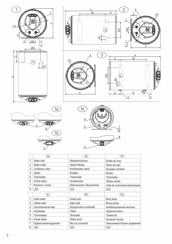
EN HOUSEHOLD ELECTRIC WATER HEATERS 30-120designed for wall installation
MANUAL FOR INSTALLATION, OPERATION AND MAINTENANCE
1c
4
13
5
8
2
2
Water inlet
Water outlet
Combined valve
Switch
Thermostat
Anode tester
Electronic control
LED
Intrare apă
Ieşire apă
Supapă/valvă combinată
Cheie
Termostat
Tester anod
Bloc de comandă
LED
1
2
3
4
5
6
7
8
EN
RO
Вход вода
Выход вода
Комбинированный вентиль
Переключатель
Термостат
Анодный тестер
Электронным блоком управления
LED
RUNL
DE FR
1
2
3
4
5
6
7
8
Wasseranschluss
Ablauf Wasser
Kombiniertes Ventil
Schalter
Thermostat
Anodentester
Elektronischen Steuereinheit
LED
Entrée de l'eau
Sortie de l'eau
Soupape combiné
Bouton
Thermostat
Testeur anode
Unité de commande électroniques
LED
Inlaat water
Uitlaat water
Gecombineerde klep
Schakelaar
Thermostaat
Anode tester
Digitaal bedieningspaneel
LED

The
val
ues
in th
e ta
bles
are
onl
y ap
prox
imat
e.
30
50
80
80
10
012
0
Fig
. 1
(1;
1a
; 1b
) /
1c
А5
60 /
56
87
60
/ 7
68
112
5 /
113
383
5 /
825
10
05
/ 1
000
10
70
/ 1
06
5
C1
55
155
155
185
/ 1
75
185
/ 1
75
185
/ 1
75
D3
87
387
387
462
/ 4
35
462
/ 4
35
462
/ 4
35
E8
080
80
96
/ 8
59
6 /
85
96 /
85
F4
10
410
410
484
/ 4
55
48
4 /
45
54
84 /
45
5
50
80
80
10
01
20
Fig
. 2
2 /
3 /
2
А76
011
25
83
51
005
1170
C1
55
155
185
18
518
5
D3
87
387
462
46
246
2
E8
080
96
96
96
F4
10
410
484
48
448
4
M4
05
77
04
15
58
775
3
B-
223
250
25
025
0
K-
617
262
43
460
0
Vo
lum
e g
rou
p /
Dim
en
sio
ns /
[mm
]
Ta
ble
Mo
de
l
Vo
lum
e g
rou
p
Dim
en
sio
ns /
[mm
]
3

4
1
2
8
9
10
EN
RO RUNL
DE FR
1
2
8
9
10
Water inlet
Water outlet
Heat exchanger I
Heat exchanger II
Thermostat coupling
Wasseranschluss
Ablauf Wasser
Wärmetauscher I
Wärmetauscher II
Thermostatmuffe
Entrée de l'eau
Sortie de l'eau
Échangeur de chaleur I
Échangeur de chaleur II
Douille de thermostat
Inlaat water
Uitlaat water
Warmtewisselaar I
Warmtewisselaar II
Mof van thermostaat
Intrare apă
Ieşire apă
Schimbător de căldură I
Schimbător de căldură II
Cuplung termostat
Вход вода
Выход вода
Теплообменник I
Теплообменник II
Муфта для термостата

5
80
100
120
80
120
100
120
Fig
. 4
5
S0.4
90.6
50.6
50.4
90.6
50.3
60.5
3
S2
--
-0.2
20.3
0.3
60.5
3
S0.6
0.8
70.8
70.6
0.8
70.5
60.6
6
S2
--
--
0.3
40.5
60.6
6
F250
250
250
250
250
250
250
J450
450
450
450
450
450
630
K-
--
770
780
365
355
L-
--
220
200
--
80
80
100
120
Fig
. 7
0.3
60.3
50.3
50.5
9
D387
462
462
462
E80
96
96
96
M770
415
587
753
C155
185
185
185
K223
250
250
250
B617
262
434
600
W410
484
484
484
Table
Model
Volu
me g
roup
Coil-
pip
es s
urf
ace
[m2]
Enamel
Dim
ensio
ns
Table
Model
Volu
me g
roup
Coil-
pip
e s
urf
ace [m
2]
Dim
ensio
ns
[mm
]

6
81
3
8
2
5
6 4 7
9
ANODETESTER
( ) – Option / Option / Options / Optie / Opţiune / Опция
EN – for water pressure in the mains above 0,5 MPaDE – bei Wasserleitungsdruck ab 0,5 MPaFR – lorsque la pression de l'eau dans le conduit passe au-dessus de 0,5 MPaNL – wanneer de waterdruk van de waterleiding meer dan 0,5 MPa isRO – la presiune în conducta de apă de peste 0.5 MPaRU – при давлении воды в водопроводе свыше 0,5 MPa
Thermal cut-outThermostatRocker switchHeaterAnode Anode testerSignal lamp / LED
1234567
Interrupteur thermiqueThermostatBoutonThermostatAnodeTesteur anodeLED
TemperatuurbegrenzerThermostaatSchakelaarVerwarmingsunitAnodeAnode testerLED
Termo-întrerupătorTermostatCheieÎncălzitorAnodTester anodLED
ТермовыключательТермостатВыключательНагревательАнодАнодный тестерLED
EN FR
RO RUNL
10
230 V
~ L
N
1 2 3 4
6 5
1 2 3
6
230 V
~ L
N
L(A1) L(A2)
N(B1) N(B2)
5
114
L(A1) L(A2)
N(B1) N(B2)
230 V
~
L
N
L L
N N
1 2
7 4
3
(B1) (B2)
(A1) (A2)
5
12
Water heaterWater inletWater outletPressure Reducing ValveSafety ReliefExp VesselNon ReturnHot water
EN
12345678
WärmeauslöserThermostatSchalterHeizelementAnode AnodentesterLED
DE
1234567

To comply with UK regulations insulation should always be in accordance to UK laws and regulations such as WRAS and G3.
YGHP strictly suggest checking installer certification and that the installer in unvented certified. While the units themselves can often be simple to install to
comply with UK laws all installers must be unvented certified.
If you are unsure on how to fit the unit please contact YGHP to prevent any install damages.
YGHP without prior communication can void warranty if the unit has been modified, damaged or installed wrong.
It is vital the units are installed to UK laws and regulations.

WARNING! Before installation and operation with the appliance, read carefully the present manual!
EN
7
KEY REQUIREMENTS FOR SAFETYBefore starting the installation of your appliance and its operation it is compulsory to read carefully the text of the instructions booklet. It is designed to familiarize you with the unit, with the rules for its proper and safe use and the minimum activities necessary to maintain and service it. Furthermore, you will need to provide this
guide for use by qualified persons who will install and repair the unit in case of failure. Installation and commissioning of the unit is not a warranty obligation of the seller and/or manufacturer.Keep this guide in a suitable place for future reference. Compliance with the rules helps for safety use of the appliance and is one of the warranty terms and conditions.
ATTENTION! Installation of the water heater and connection to the water main system should be performed only by qualified persons in accordance with the instructions in present manual and local regulations in force. Installation of safety and other components provided by the manufacturer is COMPULSORY!
ATTENTION! Connection of the water heater to the water main system should be performed only by qualified persons in accordance with the instructions in present manual and local regulations in force. The appliance should be properly connected to the current-carrying wires and the protection grid! Do not connect the appliance to the electrical installation before filling its water tank up with water! Failure to comply shall make the appliance dangerous and in such state its use is strictly forbidden!
ATTENTION! Connecting the tank with integrated heat exchangers to a local heating system (solar and/or other water heating systems using water or water solution as coolant) must be carried out by qualified and competent persons in accordance with their design. The way of use of such water heater when heating the water in its tank from an alternative electric coolant, as well as compliance with safety measures must be carried out as described in the supplementary instructions, regulations and requirements for use, servicing and maintenance. Such additional instruction booklet is provided by the company responsible for the design and installation works for connecting the tank to alternative heating sources.
WARNING! When using the appliance there is a risk of hot water scalding!
WARNING! Do not touch the appliance and its control panel with wet hands or if you are barefoot or standing on a wet spot!
WARNING! his appliance may be used by children of age over eight years old and persons with reduced physical, sensory or mental capabilities, or lack of experience and knowledge, where they are under supervision or instructed about the safe use of the appliance and understand the dangers. Children must not be allowed to play with the unit! It is absolutely forbidden that children undertake cleaning or servicing of this appliance!
ENVIRONMENTAL PROTECTIONThis appliance is marked according the REGULATION concerning waste electric and electronic equipment (WEEE). By ensuring this product is disposed of correctly, you will help prevent potential negative consequences for the environment and human health, which could otherwise be caused by inappropriate waste handling of this product.The symbol on the product, or on the accompanying
documents indicates that this appliance may not be treated as household waste. Instead it should be handed over to the applicable collection point for the recycling of electrical and electronic equipment. Disposal must be carried out in accordance with local environmental regulations for waste disposal. For more detailed information about treatment, recovery and recycling of this product, please contact your local city office, your household waste disposal service or the shop where you purchased the product.

EN
8
TECHNICAL DESCRIPTIONThe water heater is intended for domestic purposes in households, and can provide hot water from the common water main system simultaneously for a few consumers – kitchen, bathroom and etc.The heated water should be correspond to the normative documents for domestic water and, in particular: its chlorides composition should be less than 250 mg/l and its electric conductivity should be more than 100 µS/cm, while its pH within the limits of 6.5-8 for the water heaters with enameled water tanks, and electric conductivity less than 200 µS/cm for the water heaters with chrome-nickel steel water tanks. The water pressure in the water supply system should be higher than 0.1 MPa and lower than 0.5 MPa. If the water pressure is higher than 0.5 MPa - please refer to the instructions in the section for connection to the water supply network. Special water heater models are in production (for regions where local regulations require) with design to work in plumbing pressure up to 1 MPa.The appliances water containers (water tanks) are properly protected against corrosion by using high quality enameled coating, or are made of high-range alloy chrome-nickel (corrosion resistant) steel. Water tanks with enameled coating are equipped with built-in anodes made of special alloy providing additional protection.The outer casing of the appliances is made of epoxy-polymer coverage and the heat insulation is made of CFC-free polyurethane foam.Schematic views of the basic models with their modifications are shown in Fig. 1-7, and technical specifications – in Tables 1, 1a, 2 and 2a. All figures and tables are located at the beginning of this booklet.The water heater models are marked with letters and digits as follow:џ The first two letters and the following five digits indicate the
device base model.џ „W“ – the devices are designed for premise wall mounting.џ „V“ – the water heater can be installed only in a vertical
position.џ „H“ – the water heater can be installed only in a horizontal
position.џ „U“ – the water heater is with a universal mounting - can be
installed in a vertical or in a horizontal position.џ xxx – the first three digits after the letters „V“, „H“ or „U“, are
code for the water tank capacity range of the water heater.џ yy – the next two digits are code of the device diameter.џ „А“ – in the enameled water tank is built-in an anode tester
indicating the level of corrosion protection and anode wear, Fig. 1а, pos. 6џ „I“ – the water tank of the appliance is made of chrome-nickel
steel alloy.џ „S“, „S2“, „S21“ and „Т“ – in the water heater are built-in one or
two heat exchangers for water heating from an alternative heat source (local water heating, solar collector and any other similar sources), Fig. 4 for „S“ and „S2“, Fig. 5 for „S21“ and Fig. 6 for „Т“. Water heaters with a heat exchanger designed for horizontal installation, are shown in Fig.7.џ „L“ – the outlets of the heat exchanger and/or pipes for cold
and hot water of some vertical and horizontal water heaters are located on the left side of the wall-mounted unit.џ „R“ – the outlets of the heat exchanger and/or pipes for cold
and hot water of some vertical and horizontal water heaters
are located on the right side of the wall-mounted unit.џ „B“ – the outlets of cold/hot water pipes of horizontal
water heaters are located below of the wall-mounted unit.џ „D“, „C“ – within the water heaters are built-in up to
two electric heaters located in special tubes on the water tank flange. It improves the appliance safety of the device while increasing corrosion resistance. "D" - with tubular metal heating element, to 1,6 kW for units with a capacity up to 50 l (volume groups 30 and 50), up to 2 kW for units with a capacity of up to 100 l (vol. groups 80 and 100) and up to 2,4 kW for all others. "C" - with ceramic heating element, 1,5 kW for units in volume group 50, and up to 2,2 kW for the remaining.џ „Е“, „Еxy“ – the water heater is equipped with electronic
control unit for the heater or for water heaters with heat exchangers - for the heater and the devices for coolant flow control, Fig. 1b. These appliances are accompanied by additional instructions describing how to use the digital control unit.
The hot and cold water pipes are marked with colored pointers, respectively red and blue.The water heater power (excluding those with letters "D" and "C") is 1,5 kW for the units in volume group 30, up to 2 kW for the units in group 50 and 3 kW for the rest.The exact and complete model number, nominal operating parameters and serial number of purchased water heater are marked on manufacturer plate affixed on its body.
Water heaters for vertical installation. These models of heaters are designed for mounting only in a vertical position with cold and hot water pipes downward, Fig. 1 Fig. 4-6.
Water heaters for horizontal installation. These models of heaters are designed for mounting only in a horizontal position in accordance with the schema designed for each model number, Fig. 2 Fig. 3 Fig. 7
Water heaters for universal installation. These models water heaters are designed for optional vertical (Fig. 1), or horizontal installation (Fig. 2).
WARNING! When the water heater with universal installation is mounted in a horizontal position IT IS MANDATORY that the pipes for hot and cold water, and its electric control be on its left side, see Fig. 2. Failure to do so will make the unit dangerous and the manufacturer and / or the trader shall not assume any responsibility for occurrence of any adverse effects and damages!
Water heaters with heat exchanger. The water heaters of these models secure an energy efficient operation thanks to their built-in heat exchangers. The heat exchanger(s) outlets locations and their basic installation distances are shown on Fig. 4, 5, 6, 7 and Tables 2 and 2a. By using a heat exchanger bigger quantities of water inside the water container can be heated through an additional alternative energy source, i.e. local or central heating system, solar collectors and other similar sources. For more efficient heat exchanger use it is recommended to move the heat-transfer liquid with a circulation pump. For heat-transfer liquid can be used water with composition and index values within the levels laid down in the regulations related to water or a dedicated aqueous solution which is not aggressive to heat exchanger

EN
9
material. The heat-transfer liquid must be with temperature not higher than 85 °С and in its circuit must be installed a control device set at this temperature in order not to allow thermal cut-out of the electrical heating element during normal operation. The pressure of the heat-transfer liquid in the heat exchangers must not exceed the stated working pressure of the heater.
WATER HEATER INSTALLATION ON THE WALL OF THE PREMISEThe water heater can be installed only in normal fire safeguarded premises and where temperature cannot fall under 0 °C. The availability of a siphon on the installation for waste waters as during normal usage of the water heater, water may leak from the safety valve aperture. At the same time the siphon will facilitate the water tank maintenance, prevention and servicing operations when water needs to be drained out of the water tank.The type and nature of wall construction material, the appliance dimensions, the way of fixing it, the location of its fixing elements and tubes, its protection against dripping water must be taken into account when choosing the proper place for installation. All these data are duly marked on the appliance production plate with its serial number. The appliance must be mounted where it is protected against water dispersion or water pouring over. In order to reduce heat loss it is recommended to keep minimum distance between the heater and the places where the hot water is used.If you purchased a water heater with factory-fitted power cord with plug, the unit cannot be installed in a wet premise! The location of the device must comply with the requirements for the electric installation and its contact. Refer to the electrical connection of this instruction.It is obligatory that there are spaces provided between the appliance and the surrounding walls and the ceiling of the premise, as follow:џ For vertical water heaters – at least 70 mm between the
appliance and the ceiling; at least 50 mm between the appliance and the side wall; at least 350 mm below the appliance to facilitate servicing and possible repair.џ For horizontal water heaters – at least 70 mm between the
unit and the ceiling; at least 70 mm between the side cover (outlets excluded) and the wall; at least 350 mm between the electric part plastic cover and the wall to facilitate the servicing and possible repair, and a sufficient distance below the unit for installation of water connections and drain the water from the tank.џ In tanks with heat exchangers must be kept a distance from
the coil terminals side and the joints for additional thermostats necessary to connect the additional control and safety units.
Water heater should be installed steadily on the wall of the premises. For this purpose steel bolts (studs), tightly fixed in the wall, with diameter 10-12 mm are used. The fixing elements should be secured against pulling aside the wall – they should be anchor or passage bolts (depending of the wall construction material). It is recommended that the elements on which the heater will be suspended are designed for three times greater loads than the appliance total weight and located in the water therein. Installation of the water heater on decorative walls (made of single bricks or of other light materials) is strictly forbidden. On Fig. 1,2,3,7 and in the tables are shown the distances between the bolts (studs) for mounting the units.
WARNING! The bearing plates of horizontal water heaters must be securely clamped to the premise wall. Under the bolts heads (nuts on studs) must be placed support washers!WARNING! Non observance of the requirements for fixing the water heater on the wall may cause damages of the appliance, damages on other appliances and the premises, where the device is located, as well as corrosion of the casing or even more serious failures and damages. In such cases eventual failures and damages are not a subject to manufacturer and seller warranty liabilities and will be at the expense of the party which has not observed the present manual instructions.
The water heater mounting to the premise wall must be completed only by a specialist.
WATER HEATER CONNECTION TO THE WATER SUPPLY NETWORKThe plumbing to which the water heater will be connected, as well as any other elements included in it shall have to withstand sustained water temperatures above 80°C and for short periods - above 100°C, as well as to pressure at least twice high the appliance working pressure.Upon connection of the water heater to the water supply grid, the arrows and indication rings around the water heater pipes for hot and cold water must be observed (inlet and outlet pipes). With an arrow towards the pipe and blue color is marked the cold water pipe and an arrow starting from the pipe in red color - the hot water pipe. Some appliances pipes are additionally marked with badges. The pipes outlets are with threading 1/2". A schematic diagram for water heater connection is shown on Fig 8. When the water heater works at the water pipe tank pressure and that of the safety valve. In the event where the conduit pressure is greater than 0,5 MPa it shall be required the installation of reduce valve (pressure-reducing valve). Where local regulations require use of additional devices that are not included with the unit supply set and are not placed in the packaging, these must be purchased and installed according to regulations.The water heater is equipped with a combined check-safety valve. The latter is factory-fitted on the cold water pipe. Exception is made for horizontal mounted water heaters with heat exchangers or without and their modifications, where the pipes for hot and cold water pass through the cylinder of the shell of the unit. For these models the combined check-safety valve is located in a bag attached to the appliance packaging and MUST OBLIGATORY be mounted on the cold water pipe. During that installation follow the arrow on its hull showing the direction of water flow through it.
WARNING! It is FORBIDDEN to install any kind of shut-off fittings between the combined valve and the water heater! It is absolutely forbidden to obstruct the lateral opening of the combined valve and/or to block its lever!
Where the plumbing pipes are copper or of another metal, other than that of the water tank, or where brass fasteners are used, it is obligatory to install on the water tank inlet and outlet non-metallic couplings (dielectric fittings).
ATTENTION! For units with heat exchangers. Any additional tubular outlets (excluding those of the serpentines) that will be connected with the plumbing, and the holes for additional thermostats and / or thermomanometer must be closed with a package insert or other suitable for the purpose. The connections must be sealed for a water pressure of at least 1.6 Mpa.
It is recommended to set up a draining system for any dripping
EN
10
from the combined valve side opening. The draining pipe must have a constant downward slope and located in frost secure environment and its ends to be constantly kept open to the atmosphere.Once the water heater is connected to the water supply main, its water tank should be filled up with water. It is carried out in the following order:џ Open completely the turn-cock for hot water of the most
distant mixing tap.џ Open the stop valve on pos. 4 from Fig. 8.џ Wait for the air from the system to come out and over half a
minute from the fitting outlet to flow out a thick and strong water stream.џ Close the turn-cock for hot water of the mixing tap.џ lift the lever of the combined valve on pos. 5 from Fig. 8 and
wait for about 30-60 seconds until a thick and powerful stream of water runs out from the valve side opening.џ Loose the lever of the combined valve.
WARNING! If no water is coming out of the opening of the combined valve or the flow is weak (during normal water pressure), this should be considered as a malfunction indicating that impurities from the plumbing or caused by sewage connections have blocked the safety valve of the combined valve.
IT IS FORBIDDEN to proceed with appliance electric connection before eliminating the reason for malfunction!
WARNING! Failure to comply with the requirements for connection to the water supply system may cause partial filling up of the water tank and malfunction of the heating element, or when the combined valve is not installed at all or has been improperly installed this may even cause destruction of the water tank, the room and/or other damages to tangible and intangible property. Such consequences are not within the scope of manufacturer or seller warranty liabilities and shall be at the expense of the party, which has not observed the present manual instructions.
WARNING! The combined reciprocating safety valve is one of the unit safety components ensuring security for water heater users. It is specifically FORBIDDEN to use the water heater with a defective or removed/unmounted combined safety valve!
The water heater connection to the water supply system must be performed only by qualified persons.Where necessary the safety valve may serve for draining the water out of the water tank. It is carried out the following order:џ Disconnect the heater from the electrical power supply
network with the optional device and for greater security disconnect the fuse in the heater phase circuit.џ Cut the cold water access to the appliance - close the stop
cock, pos. 4 from Fig. 8.џ Open the hot water cock on the tap or disconnect the tank hot
water pipe (outlet pipe) connection.џ Lift the lever of the combined valve 5 in Fig. 8 and wait until
the water stops flowing out of the valve opening.These steps do not still secure the complete draining of the water out of the tank. It is completed only by a qualified person because it requires complete disconnection of the appliance electric circuit and dismantling the water tank flange.
WARNING! IT IS STRICTLY PROHIBITED to turn on the heater power while the water tank is partially or completely emptied of water! Do not forget to fill the tank with water before putting it
back into operation.
WARNING! The coolant circulation through the heat exchanger of a water heater equipped with such device is PROHIBITED when the water tank is partially or completely emptied of water.
WARNING! When draining the water out of the water tank all necessary precautions must be taken to prevent damages from flowing out water.
CONNECTING THE HEAT EXCHANGER OF WATER HEATER TO THE ALTERNATIVE HEAT SOURCE CIRCUITThe water heater with heat exchanger must be connected to the alternative heat source in accordance with the special additional instructions provided by the company responsible for the installation and connection of the heater design. It is mandatory to install all supplied and/or recommended by this company safety, control and coolant movement management devices.
WARNING! It is prohibited to fit stop valves on heat exchanger both ends (inlet and outlet) simultaneously. In cases where the water heater heat exchanger shall not be used and is not connected to the heat source circuit, it must be filled with propylene glycol solution suitable for heating systems.
Connecting the heat exchanger of the water heater to an alternative heat source circuit must be completed only by qualified technicians in the field from a company specializing in such services and in accordance with the design.
WATER HEATER CONNECTION TO THE POWER SUPPLY NETWORK
WARNING! Do not proceed to connect the water heater to the power supply network unless you have made sure that its water tank is full with water! Check!
The water heater is an appliance with protection degree against current damages Class I, which requires its compulsory connection to the earthling circuit of the power supply installation.The water heaters models electric circuit schema are shown on Fig. 10 and 11 (with two heaters, modifications with „D“)The electric power supply of the water heater is 230 V~ and is performed by a separate current circuit of insulated three-core
2supply cable with a cross-section of each of the wires of 2,5 mm (phase, neutral and grounding). Therefore if the in-wall cable is two-wire, a qualified electrician must add a third, protective conductor with no interruption on its track from the switchboard to the water heater. If the earthling conductor/wire has intermediate connections, latter must be secured against loosening. Otherwise the appliance shall not be correctly earthed and it shall reduce its safety.
WARNING! IT IS COMPULSORY that in the electric circuit feeding the heater is installed such a device which in the conditions of over voltage category III provides full disconnection of all poles. The conductors between the circuit and the device incoming electrical terminals must not be interrupted by any circuit breaker or fuse. Should the water heater be installed in premise with shower cubicle and/or bath the disconnecting device must be located outside.
All the extremities of wires in the appliance circuit must be properly connected to the main power switchboard and in the heater connection point to the power supply grid. In the phase circuit it is

EN
11
obligatory to install an electric fuse 10 А for water heater electric capacity up to 2 kW and 16 A for electric capacity of 3 kW. The electric installation to which the heater will be connected must be built in accordance with the requirements of the applicable statutes and local regulations in force. Where the regulations in force do not require that in the water heater circuit be installed an automatic breaker against leakage of current (residual current protection device), we recommend to install such a device. The connection of the cables from the mains switchboard to the unit terminals shall be carried out after carefully removing the plastic cover so that the electrical wiring in the unit does not disengage. In accordance with electric circuit schema glued on the cover connect the phase conductor of the power wire to the terminal marked L (or A1 depending on the version), the neutral wire to the terminal marked N (or B1) and the earthling - to the security terminal (screw or stud) marked for safety grounding. The power cord must be secured against displacement by using the cable clamp located next to the cable entry in the plastic cover. After connecting and attaching the power cable, put the plastic cover into place and secure it with screws, taking care for free movement of cables, thermostat capillary tube and the control switch.If you have purchased water heater with pre-installed power cord with a plug, the electric connection shall be carried out as the plug in put directly in a functioning and grounded socket of the premise electric installation. The socket should be on a separate, dedicated only for the water heater circuit and located so as to be easily accessible after the unit installation. The section of the electric installation wires in which the socket is placed must be suitable for the water heater electric power consumption. On the phase line must be installed a fuse (10 A for a capacity of 2 kW and 16 A for 3 kW). The installation must be carried out in compliance with the regulations in force. Taking out the power cord plug from its socket shuts down the water heater. Faulty and / or inappropriate electric installation and / or socket are high-risk conditions for accidents with damages to the product and possible damages to the environment, objects and living species.Once the appliance is connected to the power supply grid check its functionality.
WARNING! Failure to comply with the requirements concerning connection to the mains shall impede the appliance safety, in which it is prohibited to use. Adverse effects occurring as a result of non-compliance with requirements concerning the appliance electric connection are not covered by the manufacturer and seller warranty liabilities and are at the expense of the party violating the requirements of this instruction manual.
The water heater connection to the power supply and checks of its functionality shall be performed only by specialists and are not manufacturer or seller obligations and are not subject to warranty service.
HOW TO USE THE APPLIANCEThe water heater is switched on operative mode by switching the light key by pressing its extremity marked „І”. With the knob you may adjust to desired water temperature. Lighting of the key when in switched on position indicates that the water heater is operating and water is heating, while when the light is off it indicates that the water has reached adjusted temperature and the heater is switched off. You may switch off the appliance by pressing the end of the button of the glowing key marked "0". The water heater
complete disconnection from power supply takes place from the additional disconnecting device.For models marked with the letter "D" each key on the two-buttons light key located on the control dashboard serves to switch on / off one of the heaters. Thus you may use appliance half or full electric power depending on the specific needs and desired time for water heating.The chart around the thermostat knob has a distinct sector marked ECO. When the cursor of the knob is in the sector, the water is warmed to an optimum temperature at which the heat losses of the device are reduced and the reduced use of electric energy. At the same time, the warm water is sufficient for normal households. When a need for a large amount of mixed water is required the thermostat knob is rotated in the direction of travel counterclockwise to its maximum position, to reach the higher temperature of the water in the tank. We recommend to keep the knob in the sector ECO, when the heater is left on for long periods without use of hot water and only to store heated water. The appliance built-in thermostat unit has antifreeze function. When the thermostat knob is to the extreme left, at the scale beginning, the heater shall switch on at ambient temperature around 8-10°C and shall switch off at about 12-15°C. Thus in case of air temperature fall in the room, the water in the tank will be protected from freezing. ATTENTION! This feature shall not prevent the water in the room plumbing from freezing!Switching on and off, set up and using water heaters equipped with electronic control board takes place in accordance with the instructions and requirements listed in the additional manual supplied with the appliance - instruction how to connect and use an appliance with electronic control board. For such appliances the additional instruction manual is an integral part of the present installation and operation manual.The temperature indicator installed on the appliance external coating indicates the process of water heating. It is not a device for control measurement and indicates only the approximate temperature and quantity of hot water within the water tank.
WARNING! Do never switch the appliance if there is a chance that the water in the water tank is frozen! This shall damage both heater and the tank.
WARNING! This appliance may be used by children of age over eight years old and persons with reduced physical, sensory or mental capabilities, or lack of experience and knowledge, where they are under supervision or instructed about the safe use of the appliance and understand the dangers. Children must not be allowed to play with the unit! It is absolutely forbidden that children undertake cleaning or servicing of this appliance!
Within the combined valve is built a special valve which during water heater normal operation allows the expanded during heating water not to leak through the valve side hole, but to pass into cold water plumbing. The quantity of this water is negligible and usually is with low temperature. During normal operation of the water heater, as well as in present of additional return valve, it is possible that through the valve side opening leak some water drops. This

EN
12
should not be perceived as defect and the side hole of combined valve should not be blocked because it shall cause destruction of the tank. The built-in non-return valve in the combined valve prevents, in case of cutting water supply, the water in the water tank to return to cold water pipeline.Using the built-in heater exchangers (for appliances equipped with) to heat the water in the tank must take place in accordance with the instruction provided for by the persons who carried out the design and installation of the system for heating water from alternative electric sources. Compliance with the instruction in such guides is mandatory.When the appliance is used in areas with water rich in limestone it is possible to hear some noises during water heating. The noise is due to the limestone deposition on the heater and in the tank. The quantity of limestone contained depends of the type of water and its heating temperature. When the latter is higher than 60°С the quantity of separate limestone increases. Accumulated limestone impedes the heater efficiency and may even cause its failure, while increasing the time for water heating.When using the appliance it is possible to hear some weak noise due to the water flow through the pipelines and the appliance, as well as to the natural process of expanding and heating.When the heater is regularly used to heat water to a lower temperature, it is recommended to turn the thermostat knob at least once monthly to its maximum position, then to heat the water to maximum degrees and keep it such at least for 24 hours. The purpose it to prevent bacteria growth.
ADDITIONAL CORROSION PROTECTIONEnameled water heater tanks. In each water heater with enameled tank is installed additional corrosion protection. It consists of an anode of special alloy operating only when the water tank is full. The anode is a consumable (i.e. a device with normal wear during the appliance operation) and its average operational life is up to 3 (three) years. This period depends much of the type of operating the appliance and the characteristics of the heated water. After the period of operational life, a manufacturer authorized specialist or dealer service company must check the conditions of the anode. Where necessary it should be replaced with new one. Compliance with the inspection deadline and timely replacement of the anode is important for the effective protection of the tank from corrosion. Both the assessment and replacement of the anode are not subject of manufacturer and seller warranty liabilities.
Water heater with enamel tank and anode tester. The availability of the anode tester as control device is essential for the heater operation. Some water heater modifications with traditional thermostat are equipped with electromechanical anode tester (Fig. 9). It consists of a arrow-indicating system with a scale and switch (button). The scale has two sections - red and green. In tank normal operating condition the tester pointer is in the red section - the tester is not switched on and the anode is working properly. Checking the anode efficiency is carried out when the water is fully heated (switched off thermostat, i.e. the key is not lit) by pressing for few seconds the button on the tester. The arrow shall depart in the direction of the scale green sector. The magnitude of the variation is strongly affected by the parameters of the water and its temperature, as the boundary between the two sectors correspond to the water average values. The anode efficiency criterion is its arrow deflection. When at the time of pressing the
tester button, the arrow does not divert or is hold at the beginning of the red section, you should contact the specialists at your nearest manufacturer or vendor authorized service company. Their specialist shall review the tank corrosion protection and repair, if necessary. In some water heaters modifications the electronic control board indicates the anode efficiency and degree of wear with periodic regular display blinking. With advanced wear the size of lighted part decreases. More specifically the process is described in the additional instruction manual concerning the electronic control board functions. Once the lighted part of the display switches off completely you may contact the closest service company to review and eventually replace the anode.
Water tanks of high quality chrome-nickel steel. Corrosion protection and guaranteed long life are secured by correct choice of steel, adequate design and engineering construction during tank manufacture process.
SERVICE, PREVENTION, MAINTENANCEIn order to secure reliable operation of the water tank in areas with highly calcareous water it is recommended to clean the limestone accumulated within. This operation should take place at least once every two years, while in areas with higher limestone content even more frequently. The depositions on the enamel coating should not be removed otherwise than wiped with dry cotton cloth and without using hard tools. Regular limestone removal and cleaning is particularly important for appliance reliable operation. It is recommended that during this maintenance operation you carry out a review of the enameled tank anode condition. These services are not subject to warranty coverage and must be performed only by qualified person.
WARNING! In order to ensure safe and trouble-free operation of the water heater, the combined valve should be checked regularly for reduction of its permeability. This is done by lifting the lever, and wait for 30-60 seconds from the side opening the valve to flow thick and strong jet of water. This operation must be carried out after connecting the heater to the plumbing and when filling of the tank with water, in the process of using the heater not less than once every two weeks, as well as eventually after stop and start of water supply. When at full tank by opening the valve does not leak or water flow is weak, there is a failure and probably the valve is clogged by impurities in the sewage. Using water heater combined with a defective valve is strictly prohibited. Switch off immediately the appliance from the power supply and contact the nearest authorized by manufacturer service company. Otherwise, it will cause damage to the water tank, and could cause tangible and intangible damages in the room where the water heater is located.
When you are not certain about the temperature in the room where the water heater is installed, i.e. that it may fall below 0°C, the water from the water tank MUST be drained - please refer to section 'CONNECTION TO THE WATER SUPPLY NETWORK'The water heater outer shell and plastic parts can be cleaned using only a slightly damp soft cotton cloth and never with invasive and/or abrasive substances and preparations. Before cleaning the appliance, it MUST be disconnected from the power supply with the additional disconnection device or by unplugging the plug on the power cord. IT IS FORBIDDEN to clean the appliance with steam generator. Particular attention should be paid to prevent wetting of the appliance light switch on its control panel. The water heater may be switched on in operation only after complete removal of

EN
13
moisture.The rules for checking the corrosion protection and anode replacement (please refer to previous section), as well as removal of the accumulated limestone, must be strictly observed both during and after the appliance warranty period.During the appliance usage and maintenance do not damage the metal plate with its technical data and serial number. Should you take it off, keep it with the warranty form because it is the document serving to identify the water heater.
FAILURESWhen the heater does not heat the water, check if the external disconnecting device is not switched off, if the lighting key is switched off and if the thermostat knob is not turned to the lowest position. If the power supply is in order, the lighting key is switched on and the thermostat knob is turned to its highest position, but the water in the appliance is still not warming (it is possible that the lighting key or the signal lamp are lighted or not), using the external disconnecting device unplug the heater and contact the nearest authorized service company.In case when from the mixer at completely open tap for hot water there is no leakage or water flow is weak, check if the filter at the mixer outlet is not clogged, or whether the shut-off valve before the heater is not fully or partially closed (4, Fig. 8), or if water supply is not stopped. If all listed above causes are not the cause of failure, using the external disconnecting device unplug the heater and contact the nearest authorized service company.When the water heater is equipped with electronic control board, at the end of the additional instruction manual are listed the error messages appearing on the display in case of failure and what measures to take for each case. In any other general case of failure, using the external disconnecting device unplug the heater and contact the nearest authorized service company.In case of failure of the power cord and/or plug for water heaters with such, contact the nearest authorized by the manufacturer service company as the cord with plug must be replaced by the manufacturer, its service agent, or a person with similar qualifications in order to avoid danger.
WARRANTY, WARRANTY PERIOD AND WARRANTY CONDITIONSThe warranty, warranty conditions, warranty period, warranty validity for purchased appliance and service related manufacturer or vendor liabilities during the appliance warranty period are listed in the appliance warranty form. When buying the appliance the warranty form must be filled and signed both by seller and buyer. Keep the warranty form in a secure place. In all instances shall be in force the applicable laws, regulations and other legislation dealing with the rights and obligations of consumer, seller and manufacturer, and their relationships related to purchased water heater, its installation, use, servicing and maintenance. Warranty term is determined by seller and is in force only for the geographical territory of the country.Warranty is valid only if the appliance:џ Is installed according to the requirements for installation and
operation.џ Is used only as per designed purpose and in accordance with
the installation and operation manual.Warranty consists of free of charge repair of all factory defects, which may arise during the warranty term. Repair is performed by service specialists, authorized by seller. Warranty is not valid for damages, caused by:џ Improper transportationџ Improper storageџ Improper usageџ Parameters of water, different from the admissible norms for
quality of drinking water, and particularly if the composition of chlorides is more than 250 mg/l; the electrical conductivity is less than 100 μS/cm and pH is outside of 6,5-8 for water heaters with enameled water tanks; the electrical conductivity is more than 200 μS/cm for water heaters with water tanks made of chrome-nickel steel.џ Supply voltage, different than the unit's rated voltage.џ Damages due to freezing of water.џ Elemental perils, disasters and other force majeure
circumstances.џ Non observance of the installation and operation manual.џ In cases, when a non authorized person has tried to repair
any kind of a defect. In the above cases the defect will be repaired against relative payment.Warranty shall not apply to normal wear parts and components of the device, parts that are being removed during normal use, lighting and signal lamps and the like, changing the color of external surfaces, change of shape, size and location of parts and components that are exposed to impact and conditions that are not considered normal use.Lost profits, tangible and intangible damages caused by temporary inability to use the device during its prevention and repair shall not by covered by the warranty.
COMPLIANCE WITH THE REQUIREMENTS OF THIS INSTRUCTION MANUAL IS A PREREQUISITE FOR SAFE OPERATION OF YOUR PURCHASED PRODUCT AND IS ONE OF THE WARRANTY TERMS AND CONDITIONS. IT IS ABSOLUTELY PROHIBITED TO THE USER OR ANY AUTHORIZED BY HIM PERSON TO UNDERTAKE ANY CHANGES IN THE PRODUCT DESIGN AND STRUCTURE. ANY FINDING OF SUCH ACTIONS OR ATTEMPTS SHALL AUTOMATICALLY RENDER VOID ALL WARRANTY LIABILITIES OF SELLER OR PRODUCER. IN CASE OF NECESSITY FOR SERVICE SEEK ONLY MANUFACTURER AUTHORIZED SERVICE COMPANIES LISTED IN THE ANNEXED FORM. THE MANUFACTURER PRESERVED HIS RIGHT TO STRUCTURAL CHANGES WITHOUT NOTICE WHERE SUCH SHALL NOT AFFECT PRODUCT SAFETY.MANUFACTURED IN EUROPE FOR YGHP WITH ALL UK WARRANTY BEING SUPPORTED BY YGHP.