Embed Size (px)
Citation preview

www.atmorusa.com
Hot Water on Demand
Installation and Operation Guide
18kW, 21kW, 24kW, 27kW
118ºF
ThermoPro Thermostatic Series

Description Page
Safety Guidelines ..........................................................................................................................2
Technical Information .....................................................................................................................3
Plumbing .................................................................................................................................... 4-5
Mounting ........................................................................................................................................5
Installation Procedure ................................................................................................................ 6-8
Wiring ............................................................................................................................................9
Starting the system ......................................................................................................................10
Operation Guide ............................................................................................................................11
Care and Maintenance ................................................................................................................13
Troubleshooting ...........................................................................................................................14
Table of Contents
1
2
Important Safety Guidelines
SAVE THESE INSTRUCTIONS
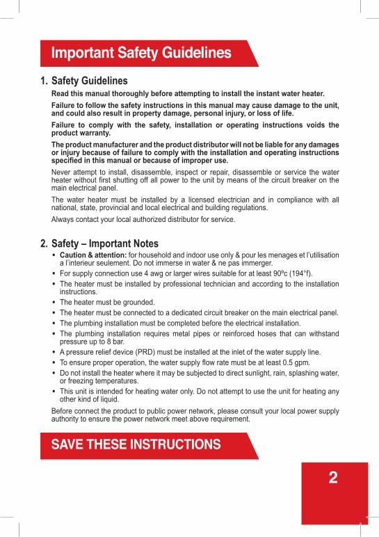
1. Safety GuidelinesRead this manual thoroughly before attempting to install the instant water heater.Failure to follow the safety instructions in this manual may cause damage to the unit, and could also result in property damage, personal injury, or loss of life.Failure to comply with the safety, installation or operating instructions voids the product warranty. The product manufacturer and the product distributor will not be liable for any damages or injury because of failure to comply with the installation and operating instructions specified in this manual or because of improper use.Never attempt to install, disassemble, inspect or repair, disassemble or service the water heater without first shutting off all power to the unit by means of the circuit breaker on the main electrical panel.The water heater must be installed by a licensed electrician and in compliance with all national, state, provincial and local electrical and building regulations.Always contact your local authorized distributor for service.
2. Safety – Important Notes • Caution & attention: for household and indoor use only & pour les menages et l’utilisation
a l’interieur seulement. Do not immerse in water & ne pas immerger. • For supply connection use 4 awg or larger wires suitable for at least 90ºc (194°f). • The heater must be installed by professional technician and according to the installation
instructions. • The heater must be grounded. • The heater must be connected to a dedicated circuit breaker on the main electrical panel. • The plumbing installation must be completed before the electrical installation. • The plumbing installation requires metal pipes or reinforced hoses that can withstand
pressure up to 8 bar. • A pressure relief device (PRD) must be installed at the inlet of the water supply line. • To ensure proper operation, the water supply flow rate must be at least 0.5 gpm. • Do not install the heater where it may be subjected to direct sunlight, rain, splashing water,
or freezing temperatures. • This unit is intended for heating water only. Do not attempt to use the unit for heating any
other kind of liquid.Before connect the product to public power network, please consult your local power supply authority to ensure the power network meet above requirement.

112 .5A
Technical InformationElectrical Specifications
ThermoPro18 kw
ThermoPro21 kw
ThermoPro24 kw
ThermoPro27 kw
Heating elements 3 3 3 3Watts 18,000 21,000 24,000 27,000Kilowatts 18 kW 21 kW 24 kW 27 kWVoltage 240 V 240 V 240 V 240 VCircuit Breaker Amperage 3 x 30 A 3 x 40 A 3 x 40 A 3 x 40 A
Breaker/Relay 3 x Single phase
Total Connection Load 75 A 87.5 A 100 ACable Size (minimum) 3 x 8 AWG 3 x 8 AWG 3 x 8 AWG 3 x 6 AWG
Plumbing SpecificationsMinimum water flow to activate unit 0.5 gpmWorking pressure 0.5–10 bar (7–145 psi)Tested pressure 20 bar (290 psi)Water connections 3/4" NPT
Flow Rate
Temperature RiseΔt (°F)
Flow Rate (gpm)
18 kwThermoPro
21 kwThermoPro
24 kwThermoPro
27 kw81 1.6 1.8 2 2.274 1.7 1.9 2.2 2.563 2 2.2 2.5 2.854 2.4 2.7 3 3.345 2.85 3.2 3.6 436 3.6 4.1 4.5 4.9
Physical DimensionsHeight Width Depth Weight13
3/8 in.
(340 mm)17
3/8 in.
(440 mm)5
1/4 in.
(135 mm)17
lbs(7.7 kg)
3
ThermoPro
double-pole3 x Single phase
double-pole3 x Single phase
double-pole3 x Single phase
double-pole

Plumbing
01 02 A pressure reduction device (PRD) must be installed on the heater’s incoming water supply line prior to installing the unit. The maximum recommended operating water pressure is 8 bar. The plumbing installation
must be completed before the electrical installation.
4
08 Before proceeding to electrical installation, run water through the unit for several minutes to flush out any air bubbles from the water line.
050403
Copper water pipes are recommended for use within three feet of the unit’s water inlet and outlet. Other types of piping can be used provided that are rated for high temperature applications.
The plumbing installation requires pipes or reinforced flexible hoses that can withstand pressure up to 8 bar and that are rated for high temperature applications.
Residential plumbing systems with unstable pressure or pressure above 5 bar require the application of a pressure stabilizer valve, set to 4–5 bar.
06 If installing the heater on an upper floor or in an attic, be sure installation is in compliance with local code. Install a drip pan with drainage, or a leak detector and automatic shutoff valve, to prevent damage in case of a leak.
07After plumbing installation is completed, carefully inspect all connections, unions, and the pressure relief device for leaks.
Mounting
01 02
06
0403
07
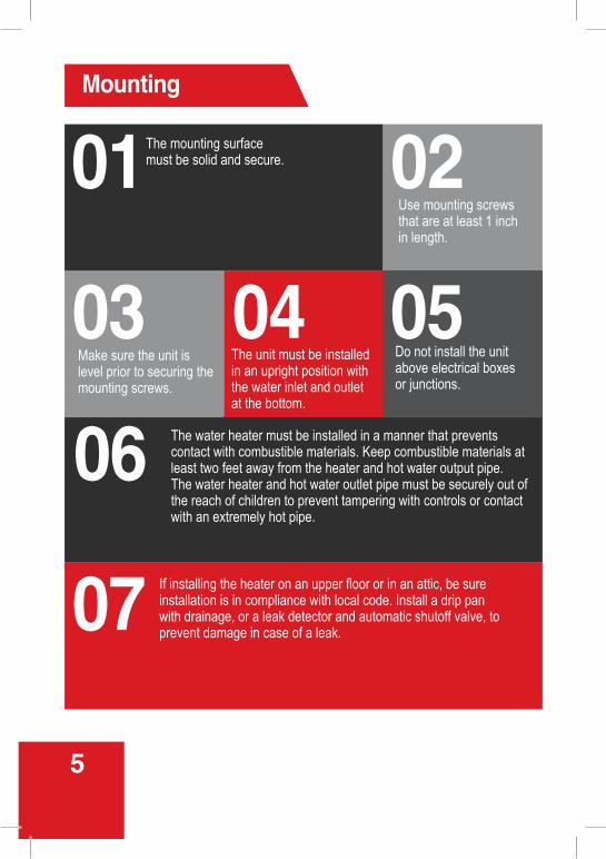
Use mounting screws that are at least 1 inch in length.
The water heater must be installed in a manner that prevents contact with combustible materials. Keep combustible materials at least two feet away from the heater and hot water output pipe.The water heater and hot water outlet pipe must be securely out of the reach of children to prevent tampering with controls or contact with an extremely hot pipe.
The mounting surface must be solid and secure.
The unit must be installed in an upright position with the water inlet and outlet at the bottom.
Make sure the unit is level prior to securing the mounting screws.
If installing the heater on an upper floor or in an attic, be sure installation is in compliance with local code. Install a drip pan with drainage, or a leak detector and automatic shutoff valve, to prevent damage in case of a leak.
5
05Do not install the unit above electrical boxes or junctions.
Assembly Instructions
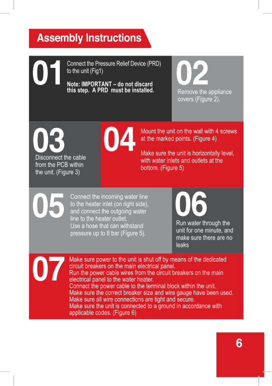
Run water through the unit for one minute, and make sure there are no leaks
01
07
06
02
05
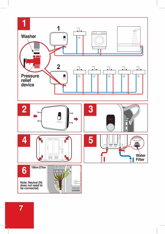
0403Remove the appliance covers (Figure 2).
Connect the Pressure Relief Device (PRD) to the unit (Fig1)
Note: IMPORTANT – do not discard this step. A PRD must be installed.
Connect the incoming water line to the heater inlet (on right side), and connect the outgoing water line to the heater outlet. Use a hose that can withstand pressure up to 8 bar (Figure 5).
Mount the unit on the wall with 4 screws at the marked points. (Figure 4)
Make sure the unit is horizontally level, with water inlets and outlets at the bottom. (Figure 5)
Disconnect the cable from the PCB within the unit. (Figure 3)
Make sure power to the unit is shut off by means of the dedicated circuit breakers on the main electrical panel. Run the power cable wires from the circuit breakers on the main electrical panel to the water heater.Connect the power cable to the terminal block within the unit.Make sure the correct breaker size and wire gauge have been used. Make sure all wire connections are tight and secure.Make sure the unit is connected to a ground in accordance with applicable codes. (Figure 6)
6
118ºF
3118ºF
2
4 5
1
6 18kw-27kw
Note: Neutral (N) does not need to be connected.
104ºF
104ºF
1
2
Washer
Pressure relief device
L1 L2 L1 L2 L1 L2
Water Filter
7

12 Do not install the heater where it may be subject to direct sunlight, and freezing temperatures.
09 1008Replace the front cover onto the unit and reattach it with 2 screws. (Figure 2)
Reconnect the cable to the PCB within the unit. (Figure 3)
Restore power to the unit by means of the dedicated circuit breakers on the main electrical panel.
Before turning on power to the water heater, open several hot water faucets and allow water to run through the unit for several minutes to purge any air from the heater and water lines. This step must be performed before turning on power to the heater. Failure to perform this step may result in permanent damage to the heating elements.
11
13 Install the unit in a location that does not require significant modifications to plumbing and near the main electrical panel.
8
Assembly Instructions
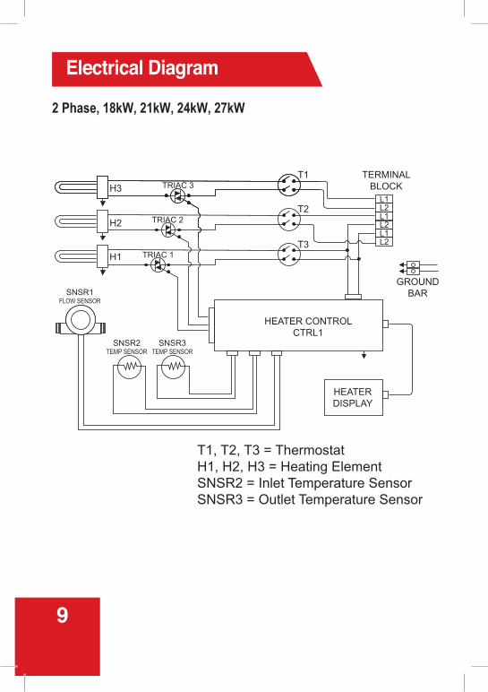
Electrical Diagram
2 Phase, 18kW, 21kW, 24kW, 27kW
H3 TRIAC 3T1
T2
T3
HEATER CONTROLCTRL1
GROUNDBAR
L1L2L1L2L1L2
HEATERDISPLAY
TRIAC 2
TRIAC 1
SNSR1FLOW SENSOR
SNSR2TEMP SENSOR
SNSR3TEMP SENSOR
H2
H1
T1, T2, T3 = ThermostatH1, H2, H3 = Heating ElementSNSR2 = Inlet Temperature SensorSNSR3 = Outlet Temperature Sensor
TERMINALBLOCK
9
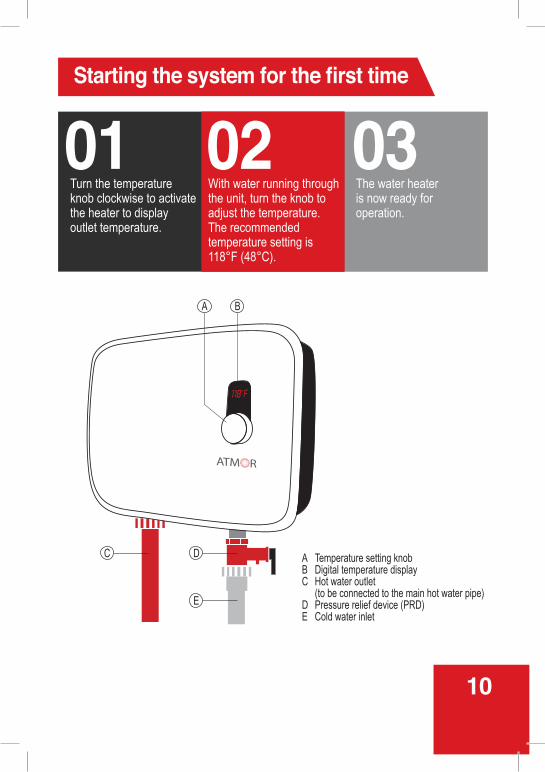
Starting the system for the first time
01 0302The water heater is now ready for operation.
With water running through the unit, turn the knob to adjust the temperature.The recommended temperature setting is 118°F (48°C).
Turn the temperature knob clockwise to activate the heater to display outlet temperature.
118ºF
A Temperature setting knobB Digital temperature displayC Hot water outlet (to be connected to the main hot water pipe)D Pressure relief device (PRD)E Cold water inlet
BA
C D
E
10
Operation GuideOperating Instructions for the Home Owner This electric water heater is designed to supply hot water for a house or apartment. Unlike a conventional tank storage water heater, this unit is a tankless water heater that does not store hot water. However, once you begin using the system, you will find it operates much like a conventional tank system.
Tankless systems deliver hot water instantaneously on demand. Since a tankless system does not waste energy continually heating water that is idly sitting and losing heat in a storage tank, it provides greater energy efficiency than a conventional system.
With your new system, as soon as you turn on a hot water faucet, the demand for hot water is detected, and high power heating elements are activated. Sensors continually monitor water flow rate and incoming and outgoing temperature, and transmit data to the system controller, which determines the exact amount of power required by heating elements to reach the set temperature.
It is important to keep in mind that all tankless water heaters are subject to a maximum flow rate. If this flow rate is exceeded, the heater will not be capable of fully heating water.
Also keep in mind that conventional tank heaters are set to high temperatures to prevent running out of hot water quickly, and thus a large amount of cold water needs to be mixed in to reach a comfortable level for washing and showering. Since this unit heats water on demand, it is designed to heat to a lower temperature. This means you only need to mix in a small amount of cold water, or none at all.
Your hot water supply may also be affected by the incoming water temperature. During winter, if incoming water temperature is very cold, you might not be able to run multiple hot water outlets at the same time. However, you can run showers back-to-back without having to wait for water to heat.
Setting the Output Water TemperatureTo set the temperature, first turn on a hot water faucet and allow water to run through the heater.
The digital display lights up and shows the current temperature setting.
To increase or lower the temperature setting, press the UP or DOWN button.
Temperature can be set to a level from 90°F to 122°F (30°C to 50°C).
A comfortable temperature for bathing and showering is between 98°F and 105°F (37°C to 41°C).
The recommended temperature setting is 118°F (48°C), which will deliver hot water for all household needs at a maximum water flow rate. A higher temperature setting is not recommended, as it can cause serious scalding injuries to children and elderly persons. Higher temperatures also produce more scale buildup in water heating devices.
11
Care and MaintenanceThe water heater has no required maintenance procedures, but periodic inspections and tests are recommended.
Remember that water heated to higher temperatures produces scale buildup much faster than at lower temperatures.
Clean the filter once a half year.
Electrical connections should be tested once a year by a qualified technician.
Plumbing connections on the water heater should be inspected at least once a year for any signs of damage or failure. If the water supply has a high level of mineralization (hard water), the water heater should be inspected and descaled more frequently.
As a result of maintenance or a water stoppage, air may be introduced into the plumbing system. Under such circumstances, follow the steps below to ensure the unit can safely resume operation.
Stopping and restarting the system due to servicing, water stoppage, or other interruptions of operation
12
Operation GuideFreezing TemperaturesIf the ambient temperature falls below 32°F (0°C), protect the heater from potential damage. Shut off power to the unit by means of the dedicated circuit breaker on the main electrical panel. Open a faucet slightly to cause water to flow continuously through the device at a very low rate, without heating. Restore power to the unit when temperature conditions allow.
If the water inside the heater freezes, it can cause damage that is not covered by warranty. If you suspect water has frozen within the unit, do not turn it on until you are certain the frozen water has melted and there are no leaks in the unit. It is recommended to contact a qualified electrician or the manufacturer for service in this situation.
Leak DetectedIf you detect a water leak from the water heater: Turn off the water supply at the shutoff valve on the unit’s incoming water supply line, shut off power to the heater, and contact your local authorized distributor for service.

13
01 020403
05
Perform the maintenance or servicing tasks.
Press the power switch to the OFF position.Shut off all power to the unit at the circuit breaker on the main electrical panel.
Reconnect power to the unit at the circuit breaker on the main electrical panel. Press the power switch to the ON position.
Open one or more hot water faucets and allow water to run through the unit for several minutes to purge any air from the heater and water lines. This step must be performed before turning on power to the heater.Failure to perform this step may cause permanent damage to the heating elements.
With water running through the unit, check and reset the temperature if necessary.The recommended temperature setting is 118°F (48°C).
Care and Maintenance
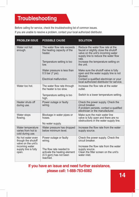
Before calling for service, check the troubleshooting list of common issues.
If you are unable to resolve a problem, contact your local authorized distributor.
Troubleshooting
PROBLEM ISSUE POSSIBLE CAUSE SOLUTION
Water not hot enough.
The water flow rate exceeds the heating capacity of the heater.
Temperature setting is too low.
Water pressure is less than 0.5 bar (7 psi).
Electrical malfunction.
Reduce the water flow rate at the faucet or slightly close the shutoff valve on the unit’s incoming water supply line to reduce the water flow rate. Increase the temperature setting on the unit.
Make sure the shutoff valve is fully open and the water supply line is not blocked. Contact a qualified electrician or your local authorized distributor for service.
Water too hot. The water flow rate through the heater is too slow.
Temperature setting is too high.
Increase the flow rate at the water outlet.
Switch to a lower temperature setting.
Heater shuts off during use.
Power outage or faulty wiring.
Check the power supply. Check the circuit breaker. If problem persists, contact a qualified electrician or the manufacturer.
Water stops flowing.
Blockage in water pipes or hoses.
No water supply.
Make sure the main water line valve is fully open and there are no obstructions in the water supply line.
Water temperature varies from hot to cold during use.
Water pressure has dropped below minimum level.
Increase the flow rate from the water supply source.
No hot water even though the shutoff valve on the unit’s incoming water supply line is fully open.
Power outage or faulty wiring.
The flow rate needed to activate the heating element (0.5 gpm) has not been reached.
Check the power supply. Check the circuit breaker.
Increase the flow rate from the water supply source.Clean the filter screen on the unit’s water inlet.
If you have an issue and need further assistance,please call: 1-888-783-6082
14
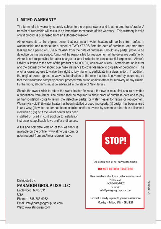
LIMITED WARRANTY The terms of this warranty is solely subject to the original owner and is at no time transferable. A transfer of ownership will result in an immediate termination of this warranty. This warranty is valid only if product is purchased from an authorized reseller.
Atmor warrants to the original owner that our instant water heaters will be free from defect in workmanship and material for a period of TWO YEARS from the date of purchase, and free from leakage for a period of SEVEN YEARS from the date of purchase. Should any part(s) prove to be defective during this period, Atmor will be responsible for replacement of the defective part(s) only. Atmor is not responsible for labor charges or any incidental or consequential expenses. Atmor’s liability is limited to the cost of the product or $1,000.00, whichever is less. Atmor is not an insurer and the original owner should purchase insurance to cover damage to property or belongings. The original owner agrees to waive their right to jury trial or to participate in a class action. In addition, the original owner agrees to waive subordination to the extent a loss is covered by insurance, so that their insurance company cannot proceed with action against Atmor for recovery of any claims. Furthermore, all claims must be arbitrated in the state of New Jersey.
Should the owner wish to return the water heater for repair, the owner must first secure a written authorization from Atmor. The owner shall be required to show proof of purchase date and to pay all transportation costs to return the defective part(s) or water heater for repair or replacement. Warranty is void if: (i) water heater has been installed or used improperly; (ii) design has been altered in any way; (iii) water heater has been installed and/or serviced by someone other than a licensed electrician ; (iv) or if the water heater has been installed or used in contradiction to installation instructions, applicable laws and/or ordinances.
A full and complete version of this warranty is available on the online, www.atmorusa.com, or upon request from an Atmor representative
P.N
. 196
183C
Distributed by:
PARAGON GROUP USA LLCEnglewood, NJ 07631USAPhone: 1-888-783-6082Email: [email protected]: www.atmorusa.com