Embed Size (px)
Citation preview
Hot Sprue BushingsProducts/Technical Guide
USB5 And SB5 Hot Sprue Bushings
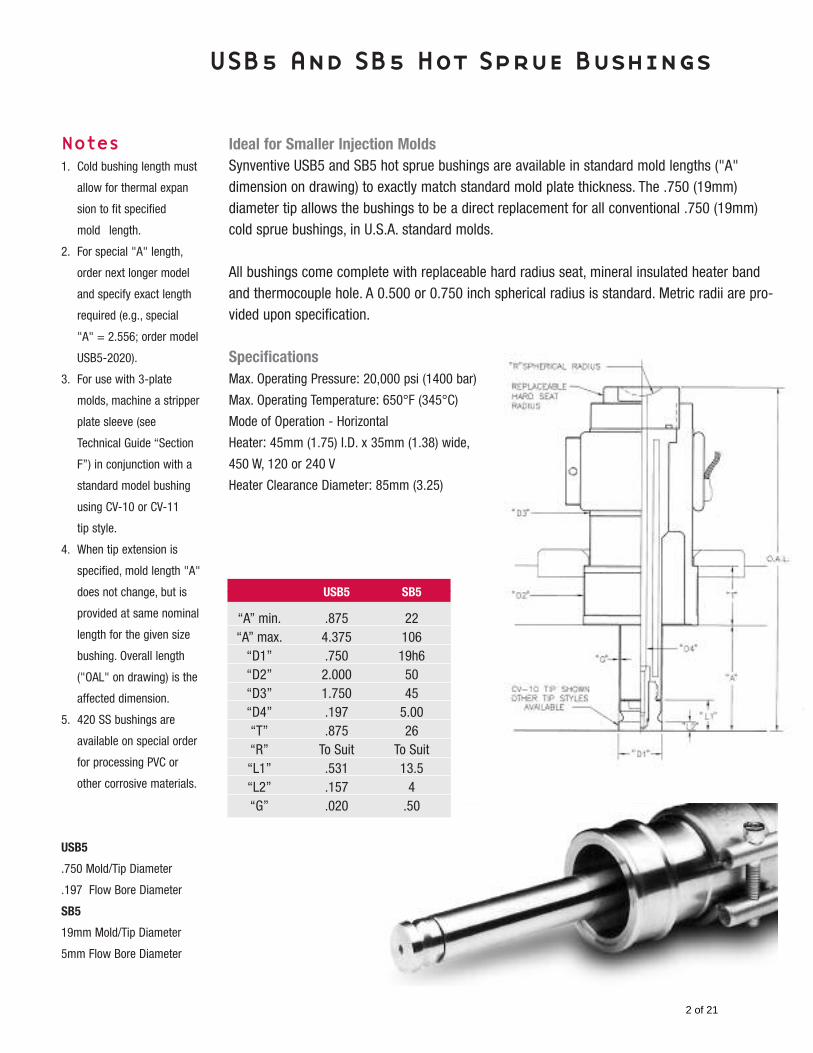
Ideal for Smaller Injection MoldsSynventive USB5 and SB5 hot sprue bushings are available in standard mold lengths ("A"dimension on drawing) to exactly match standard mold plate thickness. The .750 (19mm) diameter tip allows the bushings to be a direct replacement for all conventional .750 (19mm)cold sprue bushings, in U.S.A. standard molds.
All bushings come complete with replaceable hard radius seat, mineral insulated heater bandand thermocouple hole. A 0.500 or 0.750 inch spherical radius is standard. Metric radii are pro-vided upon specification.
SpecificationsMax. Operating Pressure: 20,000 psi (1400 bar)
Max. Operating Temperature: 650°F (345°C)
Mode of Operation - Horizontal
Heater: 45mm (1.75) I.D. x 35mm (1.38) wide,
450 W, 120 or 240 V
Heater Clearance Diameter: 85mm (3.25)
Notes1. Cold bushing length must
allow for thermal expan
sion to fit specified
mold length.
2. For special "A" length,
order next longer model
and specify exact length
required (e.g., special
"A" = 2.556; order model
USB5-2020).
3. For use with 3-plate
molds, machine a stripper
plate sleeve (see
Technical Guide “Section
F”) in conjunction with a
standard model bushing
using CV-10 or CV-11
tip style.
4. When tip extension is
specified, mold length "A"
does not change, but is
provided at same nominal
length for the given size
bushing. Overall length
("OAL" on drawing) is the
affected dimension.
5. 420 SS bushings are
available on special order
for processing PVC or
other corrosive materials.
USB5
.750 Mold/Tip Diameter
.197 Flow Bore Diameter
SB5
19mm Mold/Tip Diameter
5mm Flow Bore Diameter
USB5 SB5
“A” min. .875 22“A” max. 4.375 106
“D1” .750 19h6“D2” 2.000 50“D3” 1.750 45“D4” .197 5.00“T” .875 26“R” To Suit To Suit“L1” .531 13.5“L2” .157 4“G” .020 .50
2 of 21
Ordering information – See Worksheet Page 19
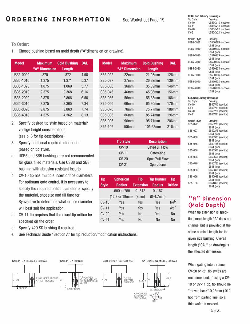
To Order:1. Choose bushing based on mold depth ("A"dimension on drawing).
2. Specify desired tip style based on material/
vestige height considerations
(see p. 6 for tip descriptions)
3. Specify additional required information
(based on tip style).
a. USB5 and SB5 bushings are not recommended
for glass filled materials. Use USB8 and SB8
bushing with abrasion resistant inserts
b. CV-10 tip has multiple insert orifice diameters.
For optimum gate control, it is necessary to
specify the required orifice diameter or specify
the material, shot size and fill time for
Synventive to determine what orifice diameter
will best suit the application.
c. CV-11 tip requires that the exact tip orifice be
specified on the order.
d. Specify 420 SS bushing if required.
e. See Technical Guide “Section A” for tip reduction/modification instructions.
USB5 Cad Library DrawingsTip Style DrawingCV-10 USB5CV10 (section)CV-11 USB5CV11 (section)CV-20 USB5CV20 (section)CV-21 USB5CV21 (section)
Nozzle Style DrawingUSB5-0022 US50022S (section)
US5T (top)USB5-1010 US51010S (section)
US5T (top)USB5-1020 US51020S (section)
US5T (top)USB5-2010 US52010S (section)
US5T (top)USB5-2020 US52020S (section)
US5T (top)USB5-3010 US53010S (section)
US5T (top)USB5-3020 US53020S (section)
US5T (top)USB5-4010 US54010S (section)
US5T (top)
SB5 Cad Library DrawingsTip Style DrawingCV-10 SB5CV10 (section)CV-11 SB5CV11 (section)CV-20 SB5CV20 (section)CV-21 SB5CV21 (section)
Nozzle Style DrawingSB5-022 SB5022S (section)
SB5T (top)SB5-027 SB5027S (section)
SB5T (top)SB5-036 SB5036S (section)
SB5T (top)SB5-046 SB5046S (section)
SB5T (top)SB5-056 SB5056S (section)
SB5T (top)SB5-066 SB5066S (section)
SB5T (top)SB5-076 SB5076S (section)
SB5T (top)SB5-086 SB5086S (section)
SB5T (top)SB5-096 SB5096S (section)
SB5T (top)SB5-106 SB5106S (section)
SB5T (top)
“A” Dimension(Mold Depth)When tip extension is speci-
fied, mold length "A" does not
change, but is provided at the
same nominal length for the
given size bushing. Overall
length ("OAL" on drawing) is
the affected dimension.
When gating into a runner,
CV-20 or -21 tip styles are
recommended. If using a CV-
10 or CV-11 tip, tip should be
"moved back" 0.25mm (.010)
hot from parting line, so a
thin wafer is molded.
Tip Style Description
CV-10 Gate/Full Flow
CV-11 Gate/Cone
CV-20 Open/Full Flow
CV-21 Open/Cone
Tip Spherical Tip Tip Runner Tip
Style Radius Extension Radius Orifice
.500 or.750 0-.312 0-.187
(12.7 or 19mm) (8mm) (0-4.7mm)
CV-10 Yes Yes Yes Nob
CV-11 Yes Yes Yes Yesc
CV-20 Yes No Yes No
CV-21 Yes No No No
Model Maximum Cold Bushing OAL
"A" Dimension Length
USB5-0020 .875 .872 4.98
USB5-1010 1.375 1.371 5.37
USB5-1020 1.875 1.869 5.77
USB5-2010 2.375 2.368 6.16
USB5-2020 2.875 2.866 6.56
USB5-3010 3.375 3.365 7.34
USB5-3020 3.875 3.863 7.74
USB5-4010 4.375 4.362 8.13
Model Maximum Cold Bushing OAL
"A" Dimension Length
SB5-022 22mm 21.93mm 126mm
SB5-027 27mm 26.92mm 136mm
SB5-036 36mm 35.89mm 146mm
SB5-046 46mm 45.86mm 156mm
SB5-056 56mm 55.83mm 166mm
SB5-066 66mm 65.80mm 176mm
SB5-076 76mm 75.77mm 186mm
SB5-086 86mm 85.74mm 196mm
SB5-096 96mm 95.71mm 206mm
SB5-106 106mm 105.68mm 216mm
3 of 21
Attn:
Fax:
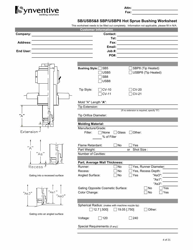
SB/USB5&8 SBP/USBP8 Hot Sprue Bushing WorksheetThis worksheet needs to be filled out completely. Information not applicable, please fill in N/A.
Company: Contact:
Tel:
Address: Fax:
Email:
End User: Job #:
PO#:
Bushing Style: SB5 SBP8 (Tip Heated)
USB5 USBP8 (Tip Heated)
SB8
USB8
Tip Style: CV-10 CV-20
CV-11 CV-21
Mold "A" Length "A":
Tip Extension:
Tip Orifice Diameter:
Manufacture/Grade:
Filler: None Glass Other:
% of Filler
Flame Retardant: No Yes
Part Weight: or Shot Size :
Number of Cavities:
Runner: No Yes, Runner Diameter:
Recess: No Yes, Recess Depth:
Angled Surface: No Yes "AsO":
"As1":
"As3":
Gating Opposite Cosmetic Surface: No Yes
Color Change: No Yes
12.7 [.500] 19.05 [.750] Other:
Voltage: 120 240
Special Requirements (if any):
Gating onto an angled surface
(If no extension is required, specify "0")
Molding Material:
Part; Average Wall Thickness:
Spherical Radius: (mates with machine nozzle tip)
Customer Information
Gating into a recessed surface
4 of 21
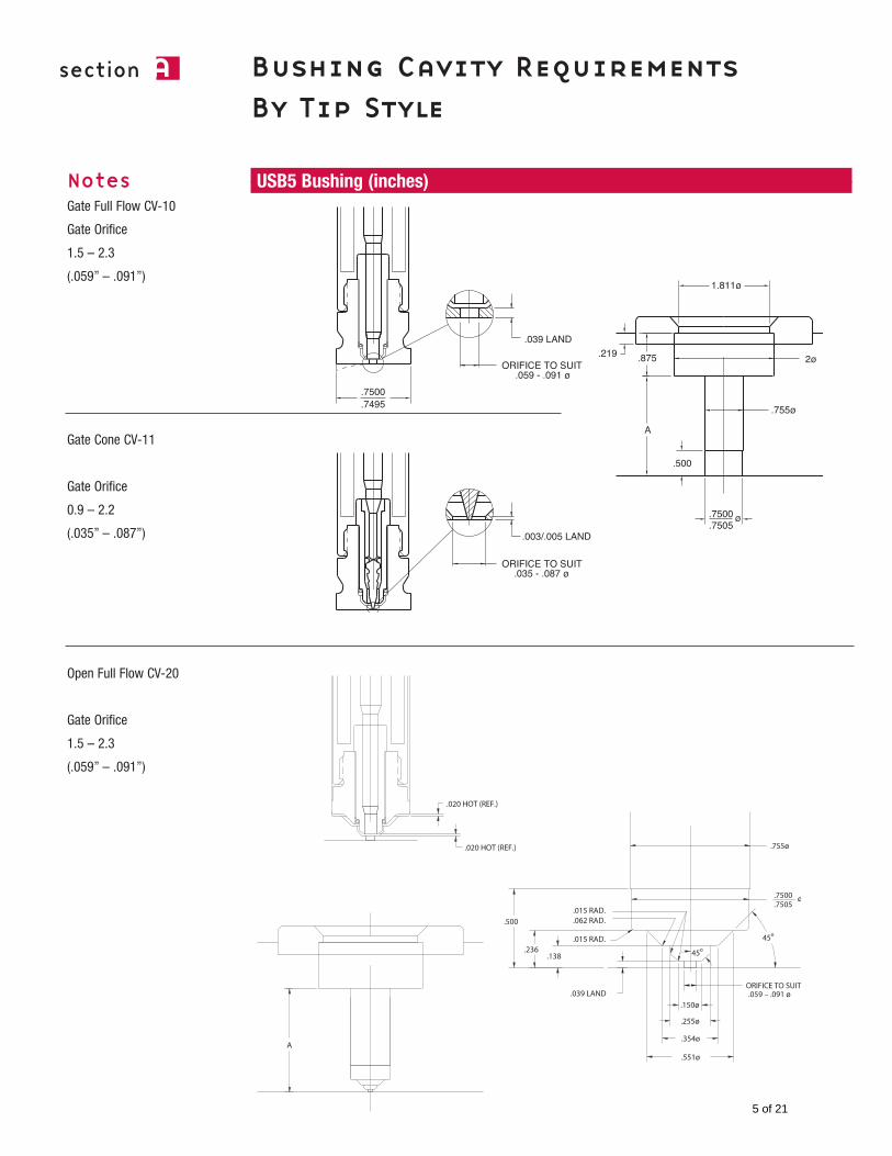
section a Bushing Cavity Requirements By Tip Style
USB5 Bushing (inches)NotesGate Full Flow CV-10
Gate Orifice
1.5 – 2.3
(.059” – .091”)
Gate Cone CV-11
Gate Orifice
0.9 – 2.2
(.035” – .087”)
Open Full Flow CV-20
Gate Orifice
1.5 – 2.3
(.059” – .091”)
5 of 21
section a
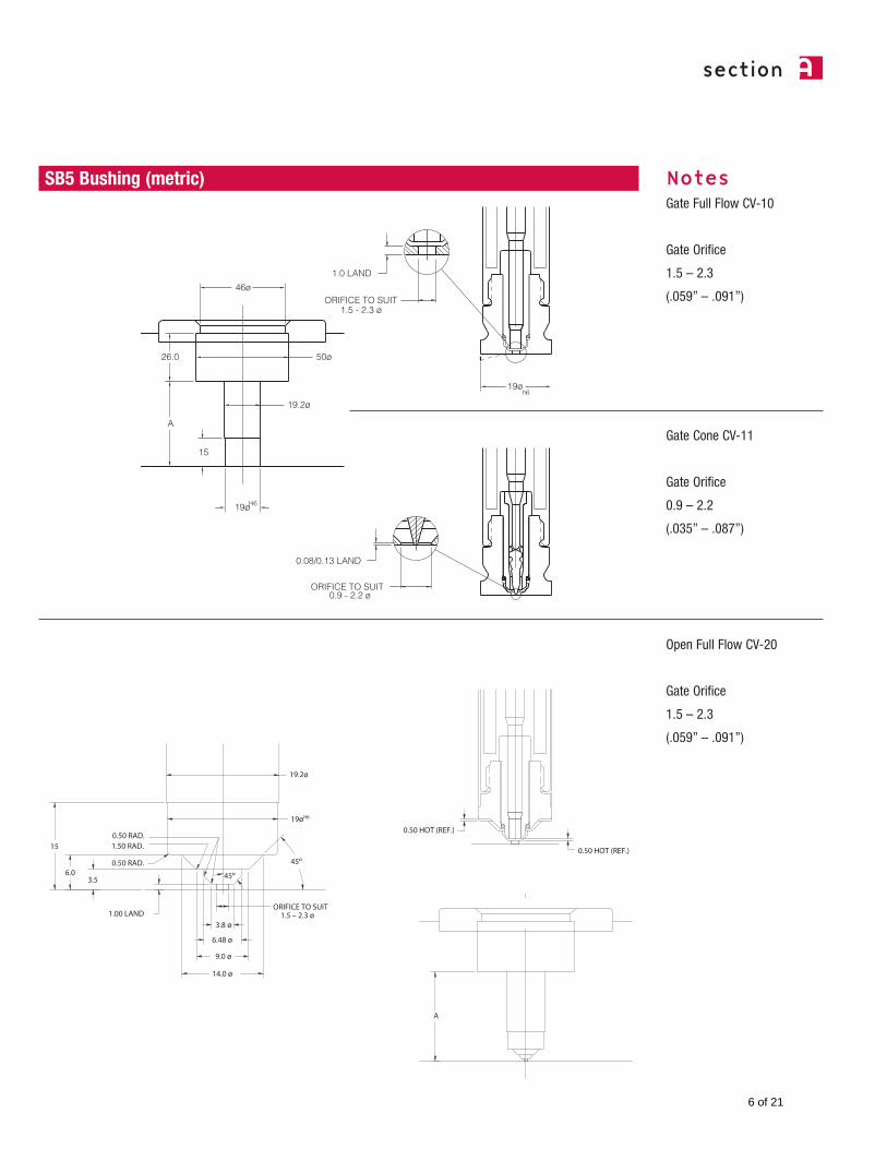
NotesGate Full Flow CV-10
Gate Orifice
1.5 – 2.3
(.059” – .091”)
Gate Cone CV-11
Gate Orifice
0.9 – 2.2
(.035” – .087”)
Open Full Flow CV-20
Gate Orifice
1.5 – 2.3
(.059” – .091”)
SB5 Bushing (metric)
6 of 21
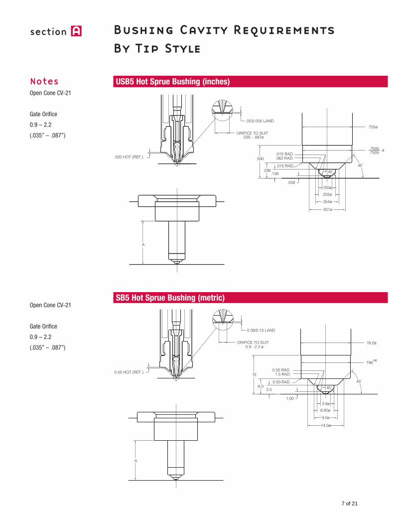
NotesOpen Cone CV-21
Gate Orifice
0.9 – 2.2
(.035” – .087”)
Open Cone CV-21
Gate Orifice
0.9 – 2.2
(.035” – .087”)
section a Bushing Cavity Requirements By Tip Style
USB5 Hot Sprue Bushing (inches)
SB5 Hot Sprue Bushing (metric)
7 of 21
section a
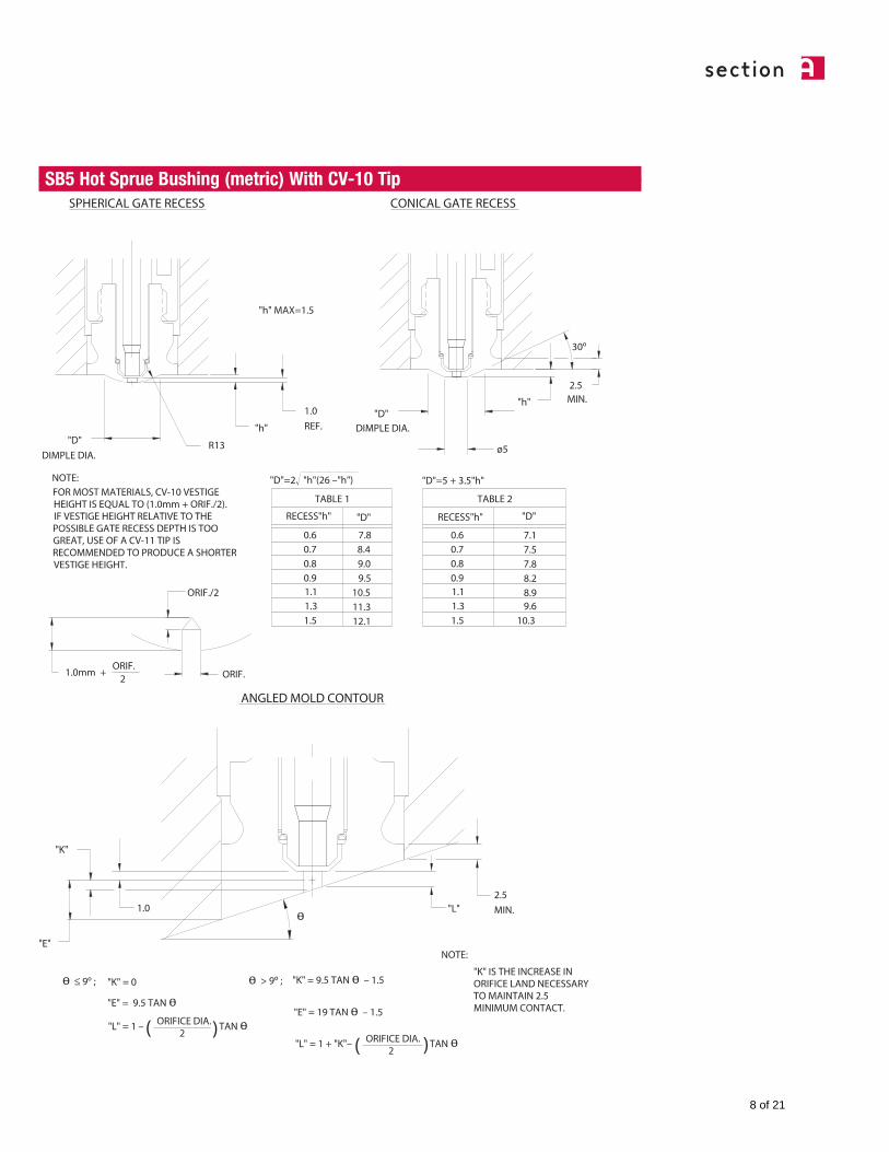
SB5 Hot Sprue Bushing (metric) With CV-10 Tip
8 of 21
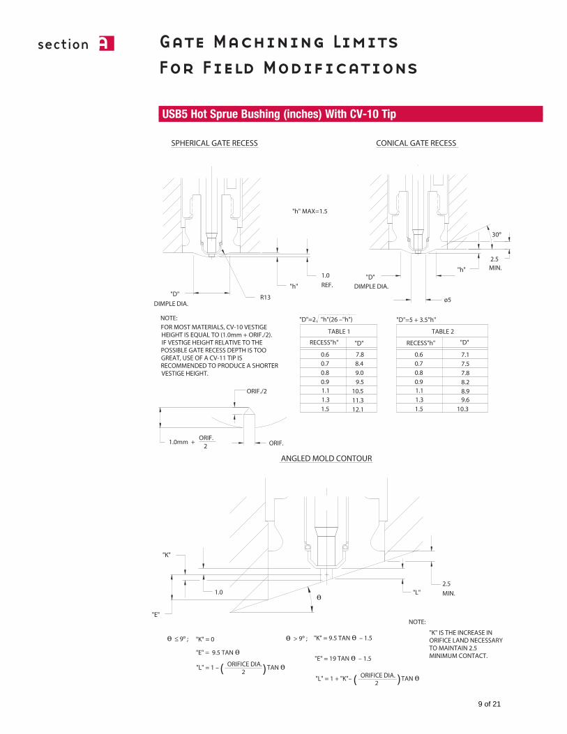
section a Gate Machining Limits For Field Modifications
USB5 Hot Sprue Bushing (inches) With CV-10 Tip
9 of 21
section a Gate Machining Limits For Field Modifications
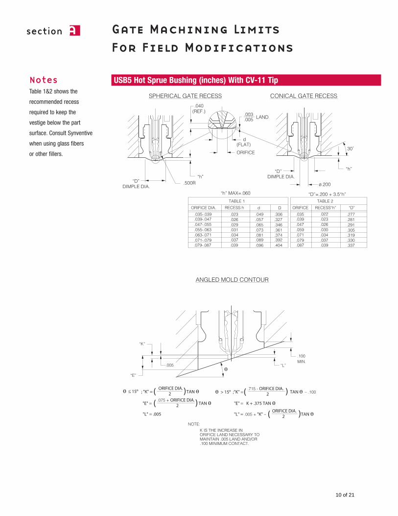
USB5 Hot Sprue Bushing (inches) With CV-11 TipNotesTable 1&2 shows the
recommended recess
required to keep the
vestige below the part
surface. Consult Synventive
when using glass fibers
or other fillers.
10 of 21
section a
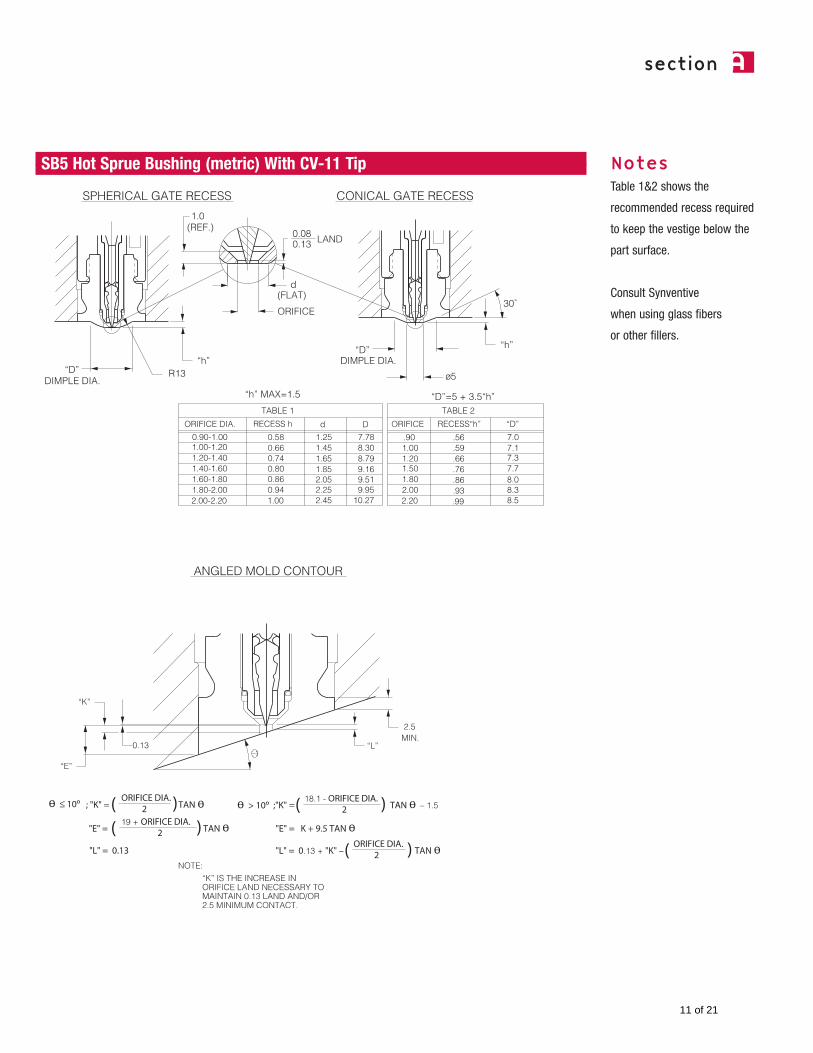
SB5 Hot Sprue Bushing (metric) With CV-11 Tip NotesTable 1&2 shows the
recommended recess required
to keep the vestige below the
part surface.
Consult Synventive
when using glass fibers
or other fillers.
11 of 21
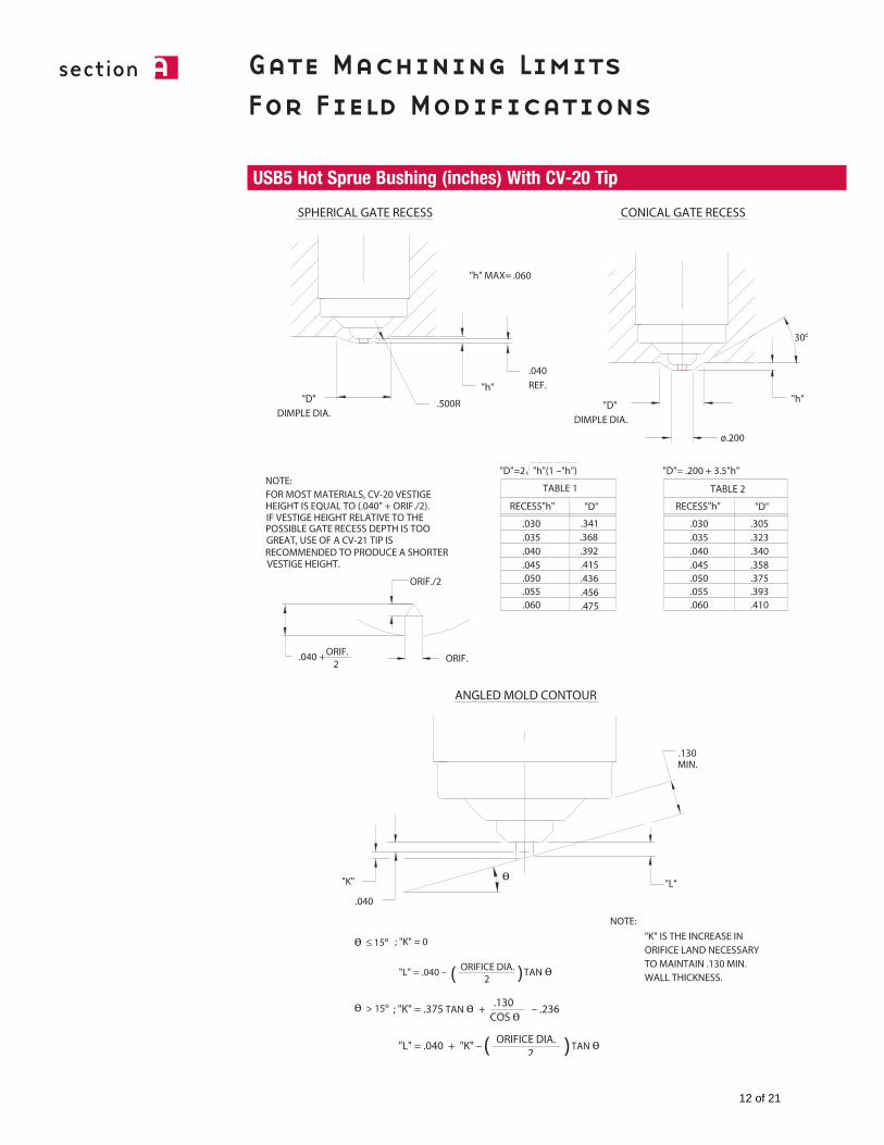
section a Gate Machining Limits For Field Modifications
USB5 Hot Sprue Bushing (inches) With CV-20 Tip
12 of 21
section a
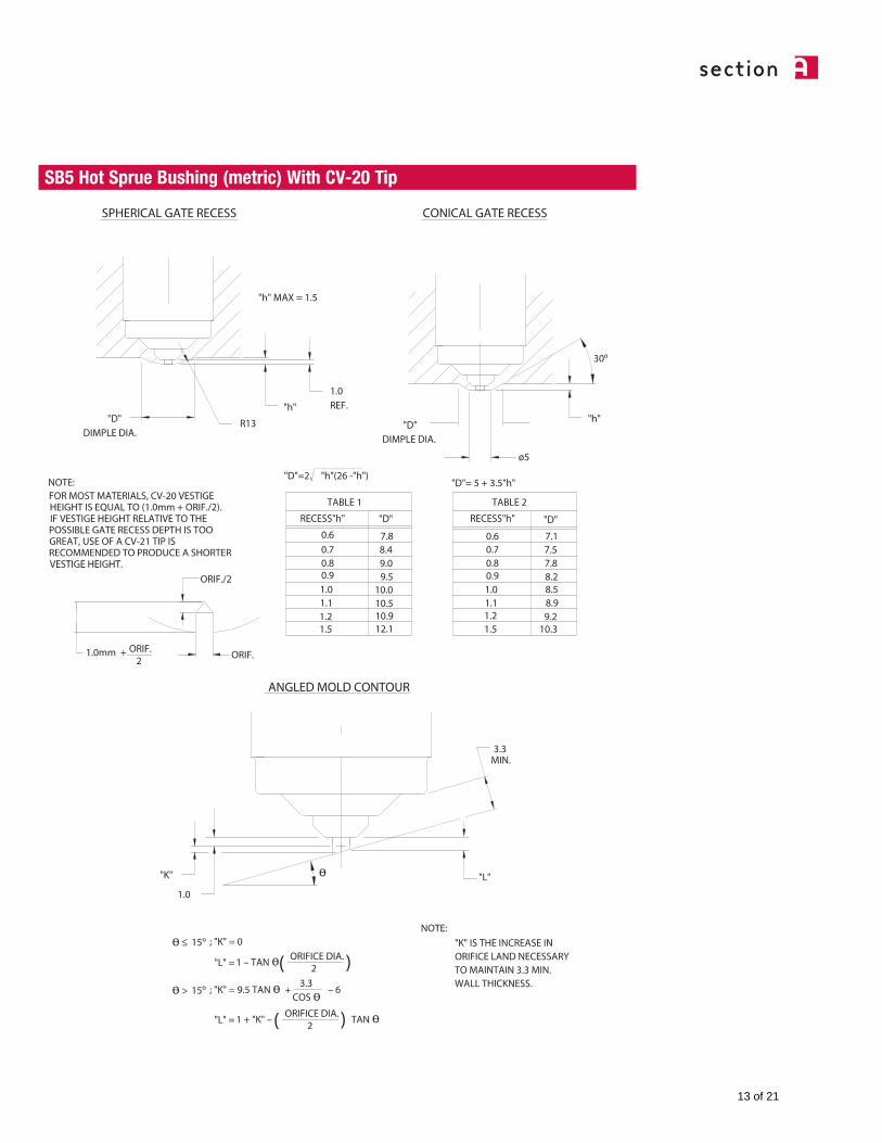
SB5 Hot Sprue Bushing (metric) With CV-20 Tip
13 of 21
section a Gate Machining Limits For Field Modifications
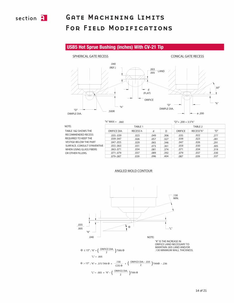
USB5 Hot Sprue Bushing (inches) With CV-21 Tip
14 of 21
section a
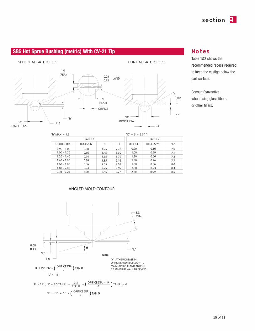
SB5 Hot Sprue Bushing (metric) With CV-21 Tip NotesTable 1&2 shows the
recommended recess required
to keep the vestige below the
part surface.
Consult Synventive
when using glass fibers
or other fillers.
15 of 21
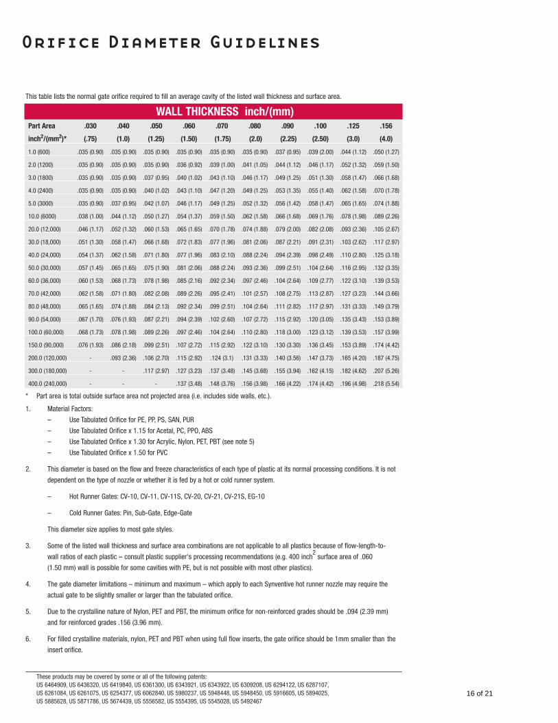
Orifice Diameter Guidelines
This table lists the normal gate orifice required to fill an average cavity of the listed wall thickness and surface area.
* Part area is total outside surface area not projected area (i.e. includes side walls, etc.).
1. Material Factors:
– Use Tabulated Orifice for PE, PP, PS, SAN, PUR
– Use Tabulated Orifice x 1.15 for Acetal, PC, PPO, ABS
– Use Tabulated Orifice x 1.30 for Acrylic, Nylon, PET, PBT (see note 5)
– Use Tabulated Orifice x 1.50 for PVC
2. This diameter is based on the flow and freeze characteristics of each type of plastic at its normal processing conditions. It is not
dependent on the type of nozzle or whether it is fed by a hot or cold runner system.
– Hot Runner Gates: CV-10, CV-11, CV-11S, CV-20, CV-21, CV-21S, EG-10
– Cold Runner Gates: Pin, Sub-Gate, Edge-Gate
This diameter size applies to most gate styles.
3. Some of the listed wall thickness and surface area combinations are not applicable to all plastics because of flow-length-to-
wall ratios of each plastic – consult plastic supplier's processing recommendations (e.g. 400 inch2
surface area of .060
(1.50 mm) wall is possible for some cavities with PE, but is not possible with most other plastics).
4. The gate diameter limitations – minimum and maximum – which apply to each Synventive hot runner nozzle may require the
actual gate to be slightly smaller or larger than the tabulated orifice.
5. Due to the crystalline nature of Nylon, PET and PBT, the minimum orifice for non-reinforced grades should be .094 (2.39 mm)
and for reinforced grades .156 (3.96 mm).
6. For filled crystalline materials, nylon, PET and PBT when using full flow inserts, the gate orifice should be 1mm smaller than the
insert orifice.
These products may be covered by some or all of the following patents:US 6464909, US 6436320, US 6419840, US 6361300, US 6343921, US 6343922, US 6309208, US 6294122, US 6287107,US 6261084, US 6261075, US 6254377, US 6062840, US 5980237, US 5948448, US 5948450, US 5916605, US 5894025,US 5885628, US 5871786, US 5674439, US 5556582, US 5554395, US 5545028, US 5492467
WALL THICKNESS inch/(mm)Part Area .030 .040 .050 .060 .070 .080 .090 .100 .125 .156
inch2/(mm2)* (.75) (1.0) (1.25) (1.50) (1.75) (2.0) (2.25) (2.50) (3.0) (4.0)
1.0 (600) .035 (0.90) .035 (0.90) .035 (0.90) .035 (0.90) .035 (0.90) .035 (0.90) .037 (0.95) .039 (2.00) .044 (1.12) .050 (1.27)
2.0 (1200) .035 (0.90) .035 (0.90) .035 (0.90) .036 (0.92) .039 (1.00) .041 (1.05) .044 (1.12) .046 (1.17) .052 (1.32) .059 (1.50)
3.0 (1800) .035 (0.90) .035 (0.90) .037 (0.95) .040 (1.02) .043 (1.10) .046 (1.17) .049 (1.25) .051 (1.30) .058 (1.47) .066 (1.68)
4.0 (2400) .035 (0.90) .035 (0.90) .040 (1.02) .043 (1.10) .047 (1.20) .049 (1.25) .053 (1.35) .055 (1.40) .062 (1.58) .070 (1.78)
5.0 (3000) .035 (0.90) .037 (0.95) .042 (1.07) .046 (1.17) .049 (1.25) .052 (1.32) .056 (1.42) .058 (1.47) .065 (1.65) .074 (1.88)
10.0 (6000) .038 (1.00) .044 (1.12) .050 (1.27) .054 (1.37) .059 (1.50) .062 (1.58) .066 (1.68) .069 (1.76) .078 (1.98) .089 (2.26)
20.0 (12,000) .046 (1.17) .052 (1.32) .060 (1.53) .065 (1.65) .070 (1.78) .074 (1.88) .079 (2.00) .082 (2.08) .093 (2.36) .105 (2.67)
30.0 (18,000) .051 (1.30) .058 (1.47) .066 (1.68) .072 (1.83) .077 (1.96) .081 (2.06) .087 (2.21) .091 (2.31) .103 (2.62) .117 (2.97)
40.0 (24,000) .054 (1.37) .062 (1.58) .071 (1.80) .077 (1.96) .083 (2.10) .088 (2.24) .094 (2.39) .098 (2.49) .110 (2.80) .125 (3.18)
50.0 (30,000) .057 (1.45) .065 (1.65) .075 (1.90) .081 (2.06) .088 (2.24) .093 (2.36) .099 (2.51) .104 (2.64) .116 (2.95) .132 (3.35)
60.0 (36,000) .060 (1.53) .068 (1.73) .078 (1.98) .085 (2.16) .092 (2.34) .097 (2.46) .104 (2.64) .109 (2.77) .122 (3.10) .139 (3.53)
70.0 (42,000) .062 (1.58) .071 (1.80) .082 (2.08) .089 (2.26) .095 (2.41) .101 (2.57) .108 (2.75) .113 (2.87) .127 (3.23) .144 (3.66)
80.0 (48,000) .065 (1.65) .074 (1.88) .084 (2.13) .092 (2.34) .099 (2.51) .104 (2.64) .111 (2.82) .117 (2.97) .131 (3.33) .149 (3.79)
90.0 (54,000) .067 (1.70) .076 (1.93) .087 (2.21) .094 (2.39) .102 (2.60) .107 (2.72) .115 (2.92) .120 (3.05) .135 (3.43) .153 (3.89)
100.0 (60,000) .068 (1.73) .078 (1.98) .089 (2.26) .097 (2.46) .104 (2.64) .110 (2.80) .118 (3.00) .123 (3.12) .139 (3.53) .157 (3.99)
150.0 (90,000) .076 (1.93) .086 (2.18) .099 (2.51) .107 (2.72) .115 (2.92) .122 (3.10) .130 (3.30) .136 (3.45) .153 (3.89) .174 (4.42)
200.0 (120,000) - .093 (2.36) .106 (2.70) .115 (2.92) .124 (3.1) .131 (3.33) .140 (3.56) .147 (3.73) .165 (4.20) .187 (4.75)
300.0 (180,000) - - .117 (2.97) .127 (3.23) .137 (3.48) .145 (3.68) .155 (3.94) .162 (4.15) .182 (4.62) .207 (5.26)
400.0 (240,000) - - - .137 (3.48) .148 (3.76) .156 (3.98) .166 (4.22) .174 (4.42) .196 (4.98) .218 (5.54)
16 of 21
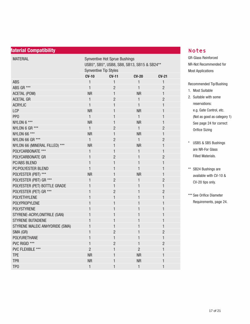
Material Compatibility
MATERIAL Synventive Hot Sprue BushingsUSB5*, SB5*, USB8, SB8, SB13, SB15 & SB24**Synventive Tip StylesCV-10 CV-11 CV-20 CV-21
ABS 1 1 1 1ABS GR *** 1 2 1 2ACETAL (POM) NR 1 NR 1ACETAL GR 1 2 1 2ACRYLIC 1 1 1 1LCP NR 1 NR 1PPO 1 1 1 1NYLON 6 *** NR 1 NR 1NYLON 6 GR *** 1 2 1 2NYLON 66 *** NR 1 NR 1NYLON 66 GR *** 1 2 1 2NYLON 66 (MINERAL FILLED) *** NR 1 NR 1POLYCARBONATE *** 1 1 1 1POLYCARBONATE GR 1 2 1 2PC/ABS BLEND 1 1 1 1PC/POLYESTER BLEND 1 1 1 1POLYESTER (PBT) *** NR 1 NR 1POLYESTER (PBT) GR *** 1 2 1 2POLYESTER (PET) BOTTLE GRADE 1 1 1 1POLYESTER (PET) GR *** 1 2 1 2POLYETHYLENE 1 1 1 1POLYPROPYLENE 1 1 1 1POLYSTYRENE 1 1 1 1STYRENE-ACRYLONITRILE (SAN) 1 1 1 1STYRENE BUTADIENE 1 1 1 1STYRENE MALEIC ANHYDRIDE (SMA) 1 1 1 1SMA (GR) 1 2 1 2POLYURETHANE 1 1 1 1PVC RIGID *** 1 2 1 2PVC FLEXIBLE *** 2 1 2 1TPE NR 1 NR 1TPR NR 1 NR 1TPO 1 1 1 1
NotesGR-Glass Reinforced
NR-Not Recommended for
Most Applications
Recommended Tip/Bushing
1. Most Suitable
2. Suitable with some
reservations:
e.g. Gate Control, etc.
(Not as good as category 1)
See page 24 for correct
Orifice Sizing
* USB5 & SB5 Bushings
are NR-For Glass
Filled Materials.
** SB24 Bushings are
available with CV-10 &
CV-20 tips only.
*** See Orifice Diameter
Requirements, page 24.
17 of 21
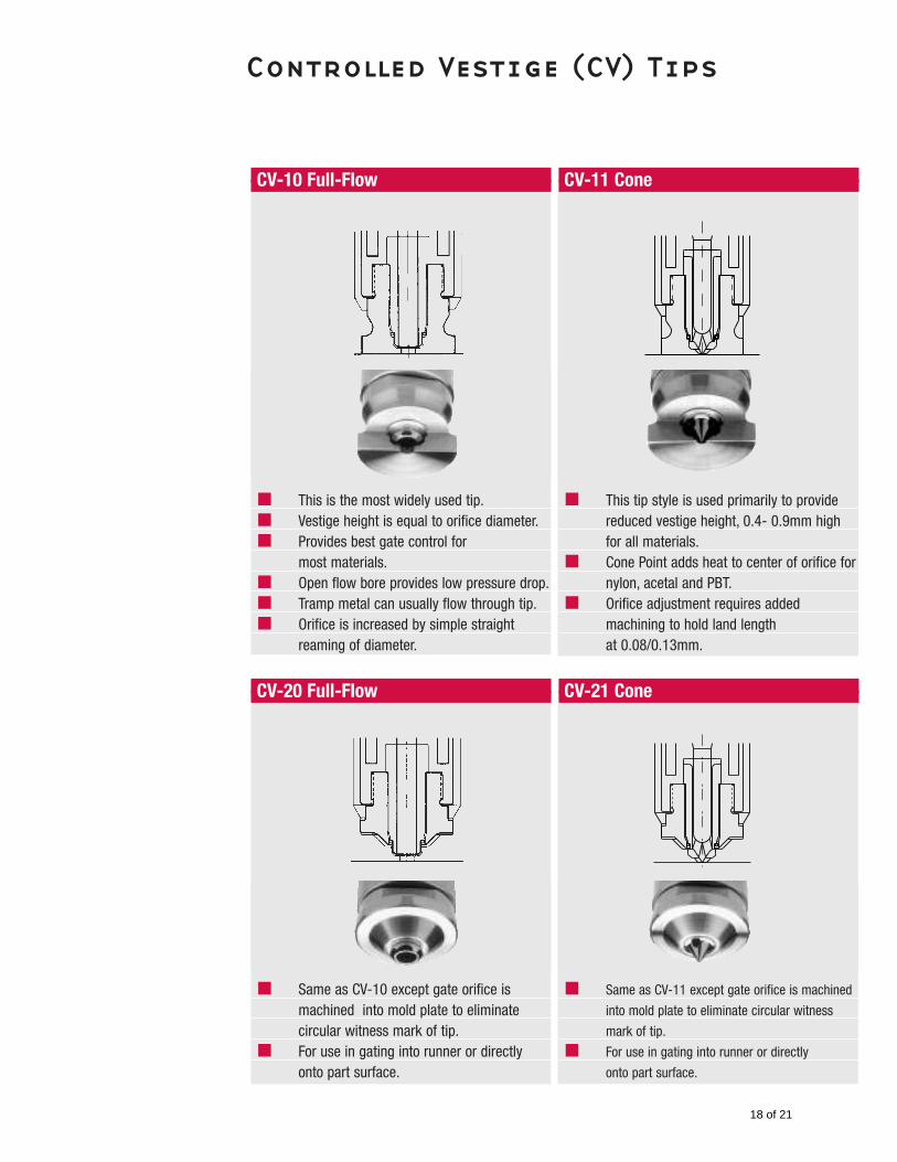
Controlled Vestige (CV) Tips
CV-10 Full-Flow
This is the most widely used tip.Vestige height is equal to orifice diameter.Provides best gate control for most materials.Open flow bore provides low pressure drop.Tramp metal can usually flow through tip.Orifice is increased by simple straight reaming of diameter.
CV-20 Full-Flow
Same as CV-10 except gate orifice is machined into mold plate to eliminate circular witness mark of tip.For use in gating into runner or directlyonto part surface.
CV-11 Cone
This tip style is used primarily to provide reduced vestige height, 0.4- 0.9mm high for all materials.Cone Point adds heat to center of orifice for nylon, acetal and PBT.Orifice adjustment requires added machining to hold land length at 0.08/0.13mm.
CV-21 Cone
Same as CV-11 except gate orifice is machined
into mold plate to eliminate circular witness
mark of tip.
For use in gating into runner or directly
onto part surface.
18 of 21
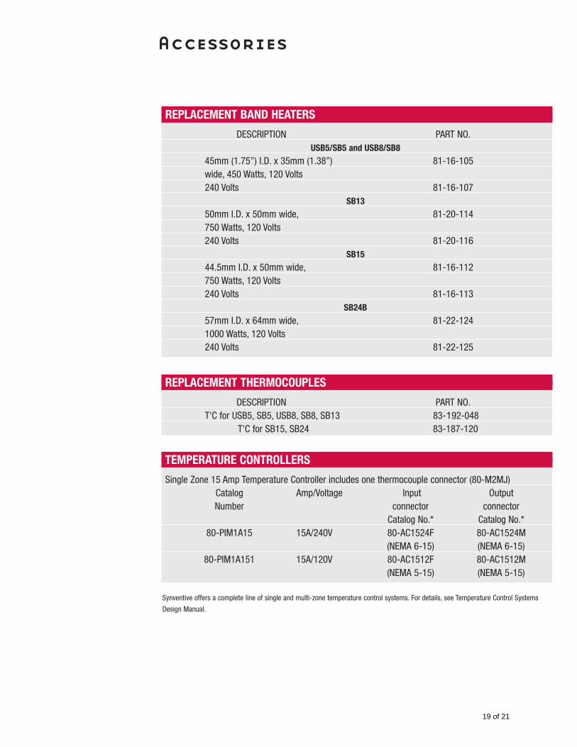
Accessories
Synventive offers a complete line of single and multi-zone temperature control systems. For details, see Temperature Control Systems
Design Manual.
REPLACEMENT BAND HEATERS
DESCRIPTION PART NO.USB5/SB5 and USB8/SB8
45mm (1.75”) I.D. x 35mm (1.38”) 81-16-105wide, 450 Watts, 120 Volts240 Volts 81-16-107
SB13
50mm I.D. x 50mm wide, 81-20-114750 Watts, 120 Volts240 Volts 81-20-116
SB15
44.5mm I.D. x 50mm wide, 81-16-112750 Watts, 120 Volts240 Volts 81-16-113
SB24B
57mm I.D. x 64mm wide, 81-22-1241000 Watts, 120 Volts240 Volts 81-22-125
REPLACEMENT THERMOCOUPLES
DESCRIPTION PART NO.T'C for USB5, SB5, USB8, SB8, SB13 83-192-048
T'C for SB15, SB24 83-187-120
TEMPERATURE CONTROLLERS
Single Zone 15 Amp Temperature Controller includes one thermocouple connector (80-M2MJ)Catalog Amp/Voltage Input OutputNumber connector connector
Catalog No.* Catalog No.*80-PIM1A15 15A/240V 80-AC1524F 80-AC1524M
(NEMA 6-15) (NEMA 6-15)80-PIM1A151 15A/120V 80-AC1512F 80-AC1512M
(NEMA 5-15) (NEMA 5-15)
19 of 21
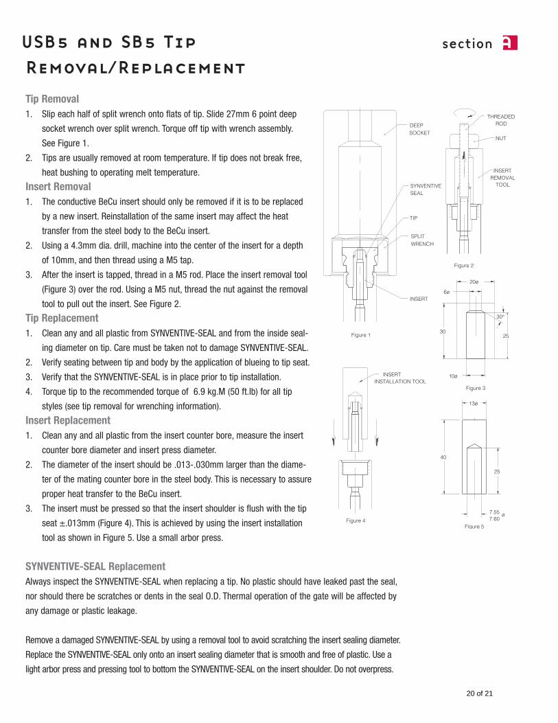
section aUSB5 and SB5 TipRemoval/ReplacementTip Removal1. Slip each half of split wrench onto flats of tip. Slide 27mm 6 point deep
socket wrench over split wrench. Torque off tip with wrench assembly.
See Figure 1.
2. Tips are usually removed at room temperature. If tip does not break free,
heat bushing to operating melt temperature.
Insert Removal1. The conductive BeCu insert should only be removed if it is to be replaced
by a new insert. Reinstallation of the same insert may affect the heat
transfer from the steel body to the BeCu insert.
2. Using a 4.3mm dia. drill, machine into the center of the insert for a depth
of 10mm, and then thread using a M5 tap.
3. After the insert is tapped, thread in a M5 rod. Place the insert removal tool
(Figure 3) over the rod. Using a M5 nut, thread the nut against the removal
tool to pull out the insert. See Figure 2.
Tip Replacement1. Clean any and all plastic from SYNVENTIVE-SEAL and from the inside seal-
ing diameter on tip. Care must be taken not to damage SYNVENTIVE-SEAL.
2. Verify seating between tip and body by the application of blueing to tip seat.
3. Verify that the SYNVENTIVE-SEAL is in place prior to tip installation.
4. Torque tip to the recommended torque of 6.9 kg.M (50 ft.lb) for all tip
styles (see tip removal for wrenching information).
Insert Replacement1. Clean any and all plastic from the insert counter bore, measure the insert
counter bore diameter and insert press diameter.
2. The diameter of the insert should be .013-.030mm larger than the diame-
ter of the mating counter bore in the steel body. This is necessary to assure
proper heat transfer to the BeCu insert.
3. The insert must be pressed so that the insert shoulder is flush with the tip
seat ±.013mm (Figure 4). This is achieved by using the insert installation
tool as shown in Figure 5. Use a small arbor press.
SYNVENTIVE-SEAL ReplacementAlways inspect the SYNVENTIVE-SEAL when replacing a tip. No plastic should have leaked past the seal,
nor should there be scratches or dents in the seal O.D. Thermal operation of the gate will be affected by
any damage or plastic leakage.
Remove a damaged SYNVENTIVE-SEAL by using a removal tool to avoid scratching the insert sealing diameter.
Replace the SYNVENTIVE-SEAL only onto an insert sealing diameter that is smooth and free of plastic. Use a
light arbor press and pressing tool to bottom the SYNVENTIVE-SEAL on the insert shoulder. Do not overpress.
20 of 21
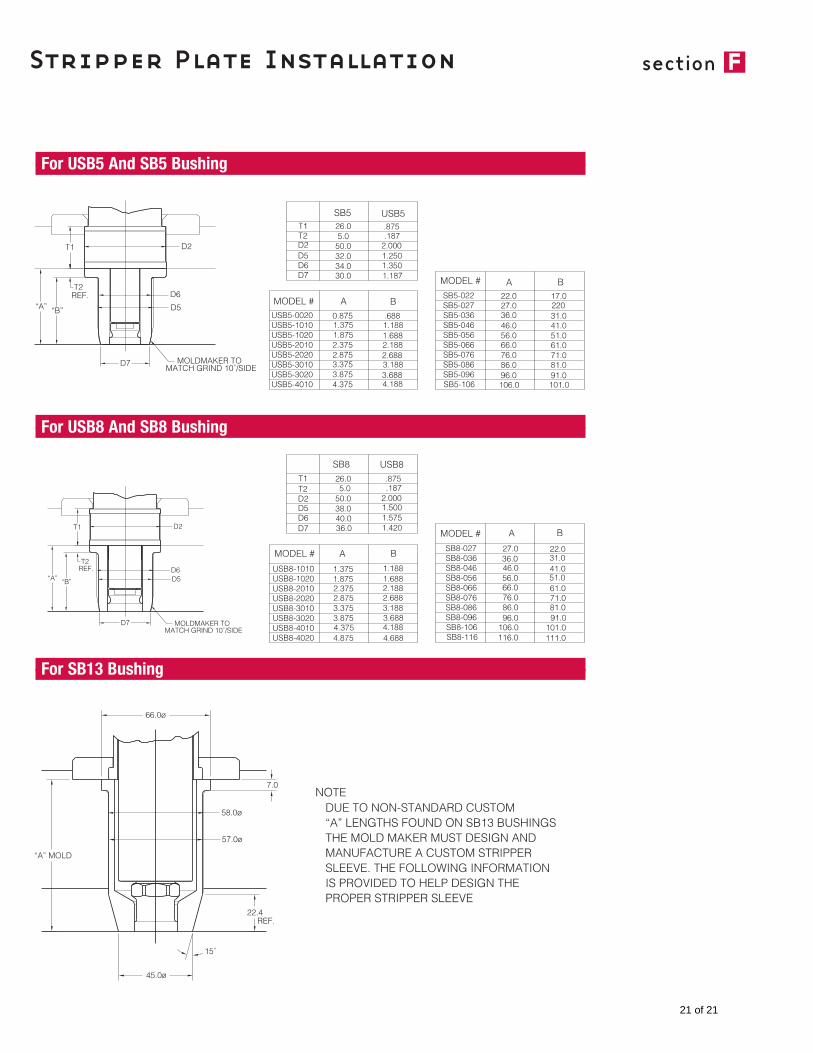
Stripper Plate Installation
For USB5 And SB5 Bushing
For USB8 And SB8 Bushing
For SB13 Bushing
section f
21 of 21