Embed Size (px)
Citation preview
S t a b i l i z e y o u r P r o c e s s
H O T R U N N E R T E C H N O L O G Y
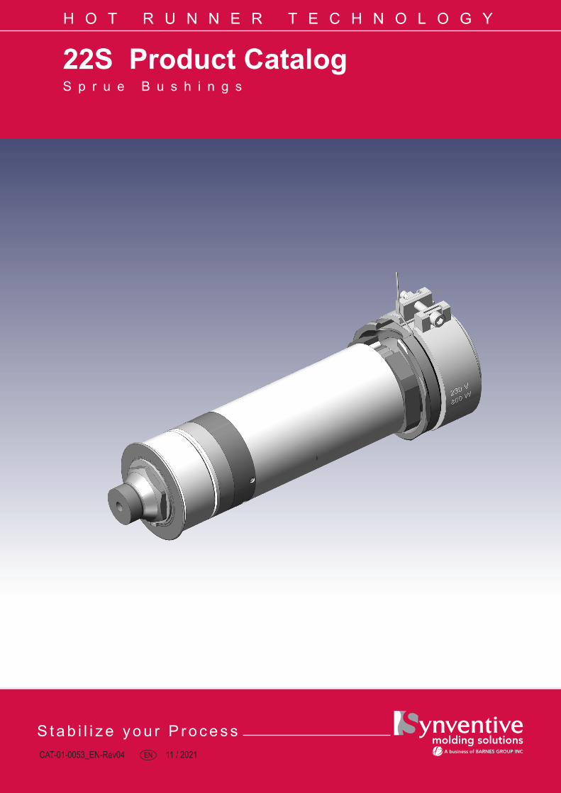
22S Product CatalogS p r u e B u s h i n g s
CAT-01-0053_EN-Rev04 EN 11 / 2021
H O T R U N N E R T E C H N O L O G Y
-2-
CAT-01-0053_EN-REV04Master Language is English For a specific application, please consult Synventive
© 2020 Synventive Molding Solutions All rights reserved. Errors and omissions excepted.
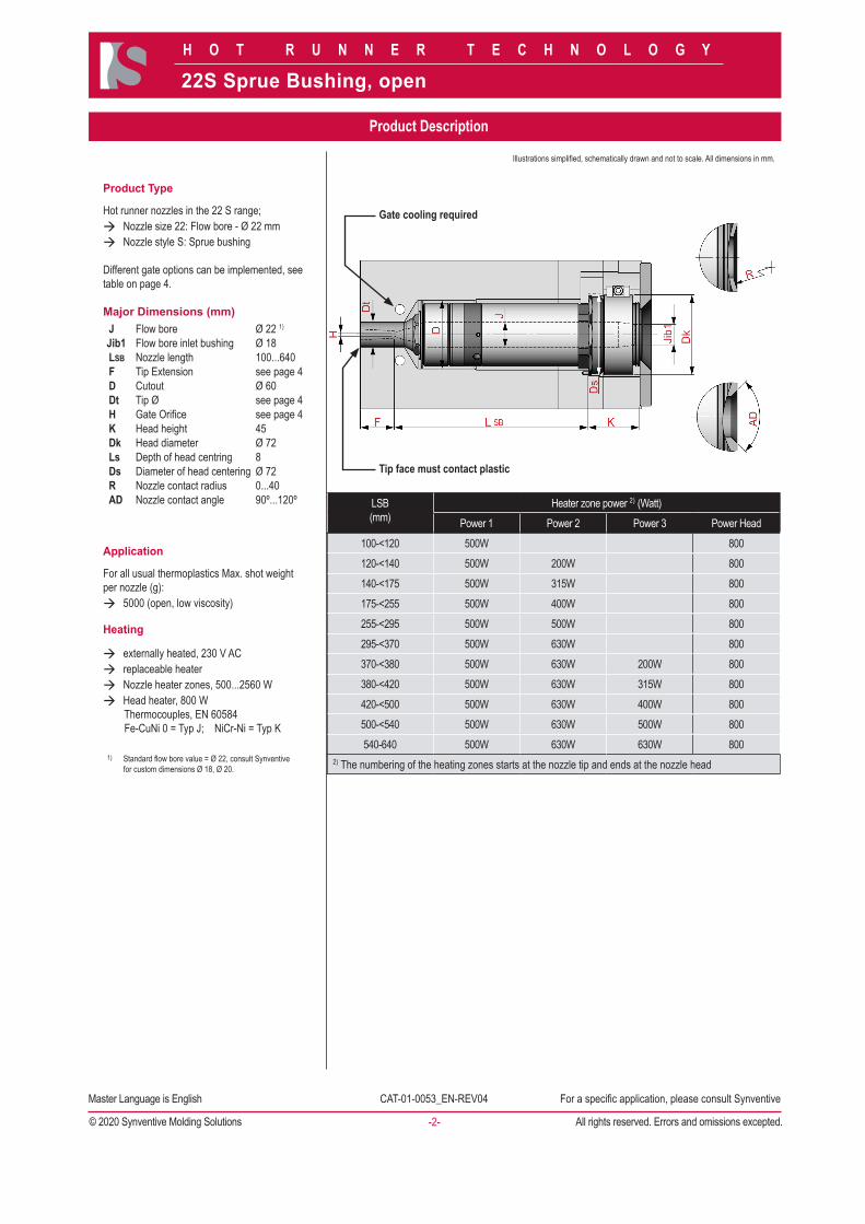
Product Type
Hot runner nozzles in the 22 S range;à Nozzle size 22: Flow bore - Ø 22 mmà Nozzle style S: Sprue bushing
Different gate options can be implemented, see table on page 4.
Major Dimensions (mm)J Flow bore Ø 22 1)
Jib1 Flow bore inlet bushing Ø 18LSB Nozzle length 100...640F Tip Extension see page 4D Cutout Ø 60Dt Tip Ø see page 4H Gate Orifice see page 4K Head height 45Dk Head diameter Ø 72Ls Depth of head centring 8Ds Diameter of head centering Ø 72R Nozzle contact radius 0...40AD Nozzle contact angle 90º...120º
Application
For all usual thermoplastics Max. shot weight per nozzle (g):à 5000 (open, low viscosity)
Heating
à externally heated, 230 V ACà replaceable heaterà Nozzle heater zones, 500...2560 Wà Head heater, 800 W Thermocouples, EN 60584 Fe-CuNi 0 = Typ J; NiCr-Ni = Typ K
1) Standard flow bore value = Ø 22, consult Synventive for custom dimensions Ø 18, Ø 20.
Gate cooling required
Tip face must contact plastic
LSB(mm)
Heater zone power 2) (Watt)Power 1 Power 2 Power 3 Power Head
100-<120 500W 800120-<140 500W 200W 800140-<175 500W 315W 800175-<255 500W 400W 800255-<295 500W 500W 800295-<370 500W 630W 800370-<380 500W 630W 200W 800380-<420 500W 630W 315W 800420-<500 500W 630W 400W 800500-<540 500W 630W 500W 800540-640 500W 630W 630W 800
2) The numbering of the heating zones starts at the nozzle tip and ends at the nozzle head
Product Description
22S Sprue Bushing, open
Illustrations simplified, schematically drawn and not to scale. All dimensions in mm.
H O T R U N N E R T E C H N O L O G Y
-3-
CAT-01-0053_EN-REV04Master Language is English For a specific application, please consult Synventive
© 2020 Synventive Molding Solutions All rights reserved. Errors and omissions excepted.
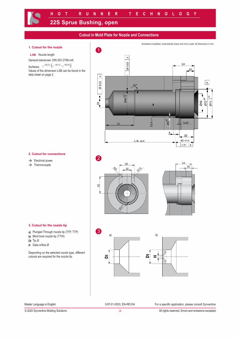
1. Cutout for the nozzle
LSB Nozzle lengthGeneral tolerances: DIN ISO 2768-mK
Surfaces: Ra 3.2 Ra 1.6 Ra 0.8( )
Values of the dimension LSB can be found in the data sheet on page 2.
2. Cutout for connections
à Electrical powerà Thermocouple
3. Cutout for the nozzle tip
a) Plunged Through nozzle tip (TFP, TTP)b) Blind bore nozzle tip (TTW)Dt Tip ØH Gate orifice Ø
Depending on the selected nozzle type, different cutouts are required for the nozzle tip.
Cutout in Mold Plate for Nozzle and Connections
22S Sprue Bushing, open
Illustrations simplified, schematically drawn and not to scale. All dimensions in mm.
Preferred Available Not Available
H O T R U N N E R T E C H N O L O G Y
-4-
CAT-01-0053_EN-REV04Master Language is English For a specific application, please consult Synventive
© 2020 Synventive Molding Solutions All rights reserved. Errors and omissions excepted.
Series 12S
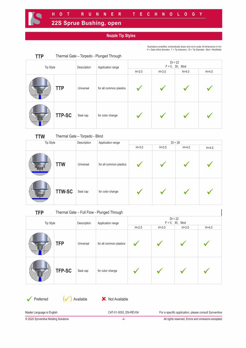
TTP Thermal Gate – Torpedo - Plunged Through
Tip Style Description Application range Dt = 22F = 0, 30, Mod
H=3.0 H=3.5 H=4.0 H=4.5
TTP Universal for all common plastics
TTP-SC Seal cap for color change
TTW Thermal Gate – Torpedo - BlindTip Style Description Application range Dt = 28
H=3.0 H=3.5 H=4.0 H=4.5
TTW Universal for all common plastics
TTW-SC Seal cap for color change
TFP Thermal Gate – Full Flow - Plunged Through
Tip Style Description Application range Dt = 22F = 0, 30, Mod
H=2.5 H=3.0 H=3.5 H=4.0
TFP Universal for all common plastics
TFP-SC Seal cap for color change
22S Sprue Bushing, open
Illustrations simplified, schematically drawn and not to scale. All dimensions in mmH = Gate orifice diameter, F = Tip extension, Dt = Tip Diameter, Mod = Modifiable
Nozzle Tip Styles
Preferred Available Not Available
H O T R U N N E R T E C H N O L O G Y
-5-
CAT-01-0053_EN-REV04Master Language is English For a specific application, please consult Synventive
© 2020 Synventive Molding Solutions All rights reserved. Errors and omissions excepted.
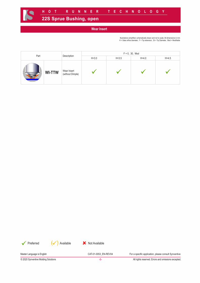
Series 12S
Part DescriptionF = 0, 30, Mod
H=3.0 H=3.5 H=4.0 H=4.5
WI-TTW Wear Insert(without Dimple)
22S Sprue Bushing, open
Illustrations simplified, schematically drawn and not to scale. All dimensions in mmH = Gate orifice diameter, F = Tip extension, Dt = Tip Diameter, Mod = Modifiable
Wear Insert
H O T R U N N E R T E C H N O L O G Y
-6-
CAT-01-0053_EN-REV04Master Language is English For a specific application, please consult Synventive
© 2020 Synventive Molding Solutions All rights reserved. Errors and omissions excepted.
22S Sprue Bushing, open
Illustrations simplified, schematically drawn and not to scale. All dimensions in mm.
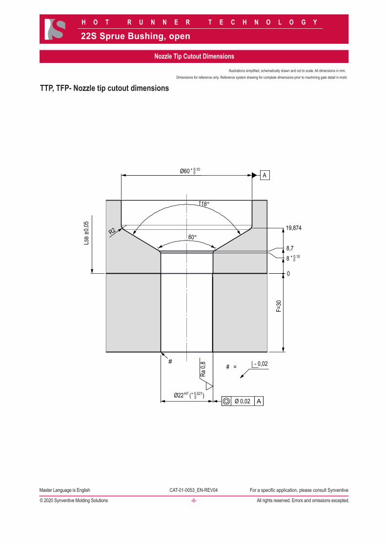
TTP, TFP- Nozzle tip cutout dimensions
Ø60
# =
R2 60°
118°
Ø22 ( )
- 0,02 #
0
8 8,7
19,874
LSB ±
0,05
F=30
Ra 0,
8
Ø 0,02 A
A
H7 + 0,021 0
+ 0,10 0
+ 0,10 0
Nozzle Tip Cutout Dimensions
Dimensions for reference only. Reference system drawing for complete dimensions prior to machining gate detail in mold.
H O T R U N N E R T E C H N O L O G Y
-7-
CAT-01-0053_EN-REV04Master Language is English For a specific application, please consult Synventive
© 2020 Synventive Molding Solutions All rights reserved. Errors and omissions excepted.
22S Sprue Bushing, open
Illustrations simplified, schematically drawn and not to scale. All dimensions in mm.
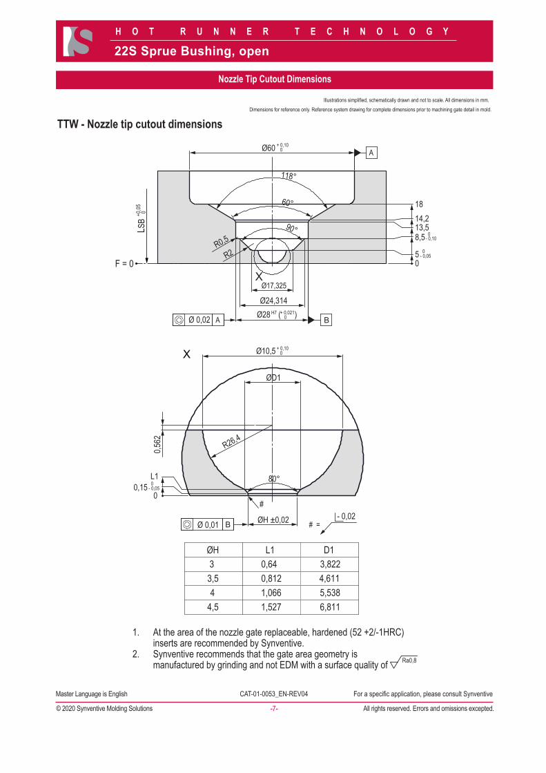
TTW - Nozzle tip cutout dimensions
At the area of the nozzle gate replaceable, hardened (52 +2/-1HRC) 1.inserts are recommended by Synventive.Synventive recommends that the gate area geometry is 2.manufactured by grinding and not EDM with a surface quality of Ra0,8
ØH L13 0,643,5 0,8124 1,066
4,5 1,527
4,6115,538
D1
6,811
3,822
+0,05
0
F = 0
LSB
Ø60
Ø28 ( ) B
B
Ø24,314
R0,5
R2 0 5 0- 0,05
0- 0,05
0- 0,108,5
13,5 14,2 18
90°
60°
118°
Ø10,5 + 0,10
0
+ 0,10 0
H7 + 0,021 0
ØD1
R26,4
80°
0,562
0 0,15
L1
Ø 0,02 A
Ø 0,01
#
ØH ±0,02 - 0,02 # =
A
Ø17,325
Nozzle Tip Cutout Dimensions
Dimensions for reference only. Reference system drawing for complete dimensions prior to machining gate detail in mold.
H O T R U N N E R T E C H N O L O G Y
-8-
CAT-01-0053_EN-REV04Master Language is English For a specific application, please consult Synventive
© 2020 Synventive Molding Solutions All rights reserved. Errors and omissions excepted.
22S Sprue Bushing, open
Illustrations simplified, schematically drawn and not to scale. All dimensions in mm.
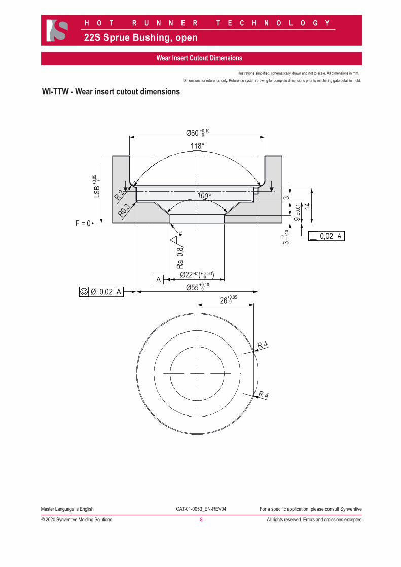
WI-TTW - Wear insert cutout dimensions
#
A
0,02 A
A 0 - 0
,10
+0,10 0
+0,05
0
+0,10 0
+0,05 0
H7 + 0,021 0
26
Ø60 118°
F = 0
R 2 R0,3
R 4
Ra 0
,8
Ø22 ( ) Ø55
100°
3 9
±0,01
14
Ø 0,02
R 4
LSB
3
Wear Insert Cutout Dimensions
Dimensions for reference only. Reference system drawing for complete dimensions prior to machining gate detail in mold.

www.synventive.com
The AmericasSynventive Molding Solutions Inc.10 Centennial DrivePeabody, MA 01960Tel.: +1 978 750 8065Fax: +1 978 646 3600Email: [email protected]
EuropeSynventive Molding Solutions GmbHHeimrodstraße 10P. O. Box 312364625 BensheimTel. :+49 (0)6251 9332-0Fax :+49 (0)6251 9332-90Email: [email protected]
AsiaSynventive Molding Solutions (Suzhou) Co. Ltd.12B Gang Tian Industrial SquareSuzhou Industrial Park, China 215021Tel.: +86 512 6283 8870Fax: +86 512 6283 8890Email: [email protected]
CAT-01-0053_EN-REV04 2021-Nov-29 © 2021 Synventive Molding Solutions DTP: RS


![Fusion Splicer - slimdata.ru · This fusion splicer 22S is a fusion splicer which can connect a single optical fiber. Moreover, a new function was added and made the manual. [22S]](https://img.pdfslide.us/doc/110x75/5f033dcf7e708231d4083ca8/fusion-splicer-this-fusion-splicer-22s-is-a-fusion-splicer-which-can-connect-a.jpg)