Embed Size (px)
Citation preview

Order code: EQLED089
Hot RodUser Manual
www.prolight.co.uk Hot Rod User Manual 2
Safety advice
WARNINGFOR YOUR OWN SAFETY, PLEASE READ THIS USER MANUAL CAREFULLY BEFORE YOUR INITIAL START-UP!• Beforeyourinitialstart-up,pleasemakesurethatthereisnodamagecausedduringtransportation.
• Shouldtherebeanydamage,consultyourdealeranddonotusetheequipment.
• Tomaintaintheequipmentingoodworkingconditionandtoensuresafeoperation,itisnecessaryfortheusertofollowthesafetyinstructionsandwarningnoteswritteninthismanual.
• Pleasenotethatdamagescausedbyusermodificationstothisequipmentarenotsubjecttowarranty.
IMPORTANT:The manufacturer will not accept liability for any resulting damages caused by the non-observance of this manual or any unauthorised modification to the equipment.
OPERATING DETERMINATIONSIfthisequipmentisoperatedinanyotherway,thanthosedescribedinthismanual,theproductmaysufferdamageandthewarrantybecomesvoid.Incorrectoperationmayleadtodangere.g:short-circuit,burnsandelectricshocksetc.
Donotendangeryourownsafetyandthesafetyofothers!
Incorrectinstallationorusecancauseseriousdamagetopeopleand/orproperty.
CAUTION!KEEP THIS EQUIPMENT AWAY FROM RAIN, MOISTURE AND LIQUIDS
CAUTION! TAKE CARE USING THIS EQUIPMENT!HIGH VOLTAGE-RISK OF ELECTRIC SHOCK!!
• Neverletthepowercablecomeintocontactwithothercables.Handlethepowercableandallmainsvoltageconnectionswithparticularcaution!
• Neverremovewarningorinformativelabelsfromtheunit.
• Donotopentheequipmentanddonotmodifytheunit.
• Donotconnectthisequipmenttoadimmerpack.
• Donotswitchtheequipmentonandoffinshortintervals,asthiswillreducethesystem’slife.
• Onlyusetheequipmentindoors.
• Donotexposetoflammablesources,liquidsorgases.
• Alwaysdisconnectthepowerfromthemainswhenequipmentisnotinuseorbeforecleaning!Onlyhandlethepower-cablebytheplug.Neverpullouttheplugbypullingthepower-cable.
• Makesurethattheavailablemainssupplyvoltageisbetween100~240VAC,50/60Hz.
• Makesurethatthepowercableisnevercrimpedordamaged.Checktheequipmentandthepowercableperiodically.
• Iftheequipmentisdroppedordamaged,disconnectthemainspowersupplyimmediatelyandhaveaqualifiedengineerinspecttheequipmentbeforeoperatingagain.
• Iftheequipmenthasbeenexposedtodrastictemperaturefluctuation(e.g.aftertransportation),donotconnectpowerorswitchitonimmediately.Thearisingcondensationmightdamagetheequipment.Leavetheequipmentswitchedoffuntilithasreachedroomtemperature.
• Ifyourproductfailstofunctioncorrectly,stopuseimmediately.Packtheunitsecurely(preferablyintheoriginalpackingmaterial),andreturnittoyourProLightdealerforservice.
• Onlyusefusesofsametypeandrating.
• Repairs,servicingandpowerconnectionmustonlybecarriedoutbyaqualifiedtechnician.THISUNITCONTAINSNOUSERSERVICEABLEPARTS.
• Thislightingfixtureisforprofessionaluseonly-itisnotdesignedfororsuitableforhouseholduse.Theproductmustbeinstalledbyaqualifiedtechnicianinaccordancewithlocalterritoryregulations.Thesafetyoftheinstallationistheresponsibilityoftheinstaller.Thefixturepresentsrisksofsevereinjuryordeathduetofirehazards,electricshockandfalls.
• Warning!RiskGroup2LEDproductaccordingtoEN62471.Donotviewthelightoutputwithopticalinstrumentsoranydevicethatmayconcentratethebeam.
• WARRANTY:Oneyearfromdateofpurchase.
www.prolight.co.uk Hot Rod User Manual 3
Product overview & technical specifications
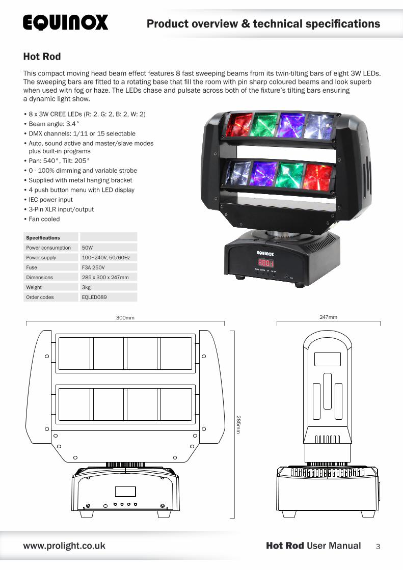
Thiscompactmovingheadbeameffectfeatures8fastsweepingbeamsfromitstwin-tiltingbarsofeight3WLEDs.Thesweepingbarsarefittedtoarotatingbasethatfilltheroomwithpinsharpcolouredbeamsandlooksuperbwhenusedwithfogorhaze.TheLEDschaseandpulsateacrossbothofthefixture’stiltingbarsensuringadynamiclightshow.
•8x3WCREELEDs(R:2,G:2,B:2,W:2)
•Beamangle:3.4°
•DMXchannels:1/11or15selectable
•Auto,soundactiveandmaster/slavemodesplusbuilt-inprograms
•Pan:540°,Tilt:205°
•0-100%dimmingandvariablestrobe
•Suppliedwithmetalhangingbracket
•4pushbuttonmenuwithLEDdisplay
•IECpowerinput
•3-PinXLRinput/output
•Fancooled
Hot Rod
Specifications
Powerconsumption 50W
Powersupply 100~240V,50/60Hz
Fuse F3A250V
Dimensions 285x300x247mm
Weight 3kg
Ordercodes EQLED089
285mm
300mm 247mm
www.prolight.co.uk Hot Rod User Manual 4
Technical specifications
DMX INPUT DMX OUTPUT
FUSE: F3A 250Vwww.prolight.co.uk
POWER INPUT:100-240V~50/60Hz
MICMENU DOWNUP ENTER
02 0301 04 05 07 0806
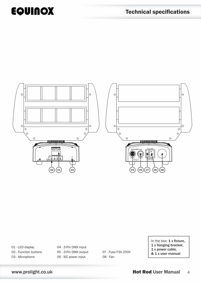
01-LEDdisplay
02-Functionbuttons
03-Microphone
04-3-PinDMXinput
05-3-PinDMXoutput
06-IECpowerinput
07-FuseF3A250V
08-Fan
Inthebox:1 x fixture, 1 x hanging bracket, 1 x power cable, & 1 x user manual
www.prolight.co.uk Hot Rod User Manual 5
Operating instructionsOperating instructions
MENU
1
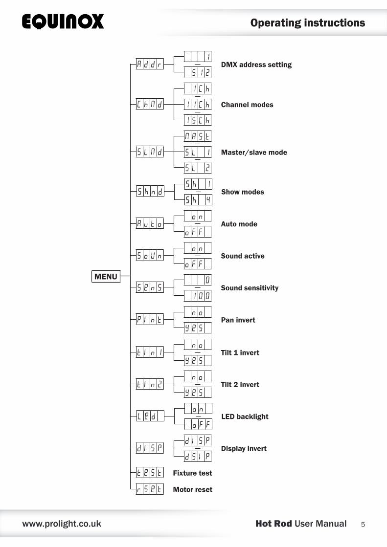
5 1 2A d d r DMX address setting
1 C h
1 1 C h
1 5 C h
C h N d Channel modes
N A s t
S L 1
S L 2
S L N d Master/slave mode
S h 1
S h 4S h n d Show modes
0
1 0 0S e n S Sound sensitivity
o n
o F FS o U n Sound active
o n
o F FA u t o Auto mode
n o
y e sP I n t Pan invert
n o
y e st I n 1 Tilt 1 invert
n o
y e st I n 2 Tilt 2 invert
o n
o F FL e d LED backlight
d I S P
d S I pd I S P Display invert
t e S t Fixture test
r s e t Motor reset
www.prolight.co.uk Hot Rod User Manual 6
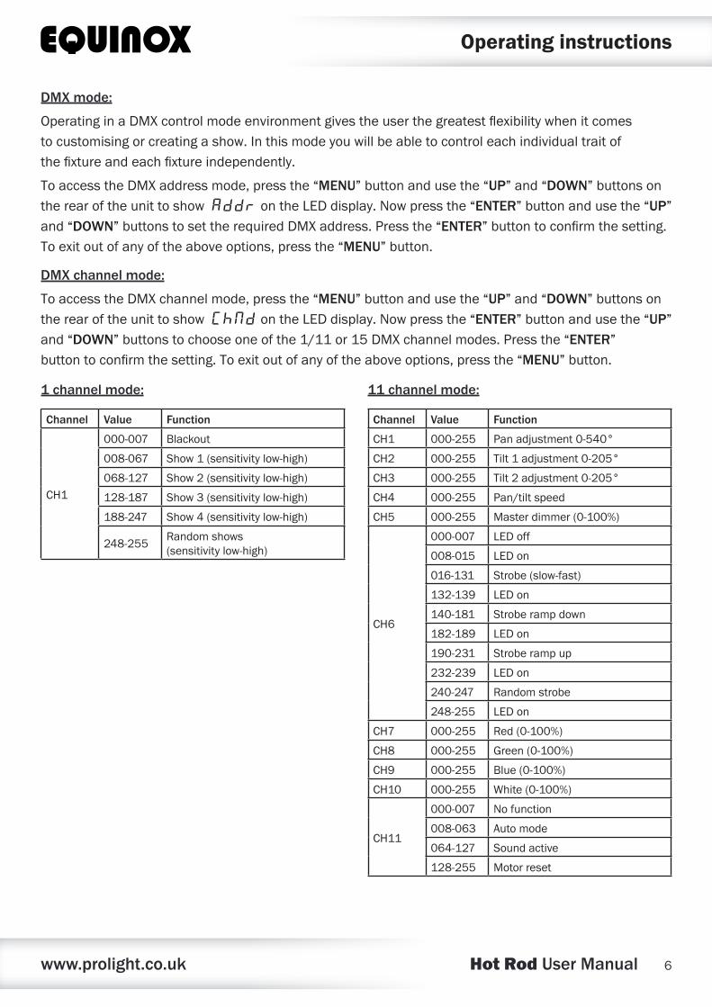
DMX mode:
OperatinginaDMXcontrolmodeenvironmentgivestheuserthegreatestflexibilitywhenitcomestocustomisingorcreatingashow.Inthismodeyouwillbeabletocontroleachindividualtraitofthefixtureandeachfixtureindependently.
ToaccesstheDMXaddressmode,pressthe“MENU”buttonandusethe“UP”and“DOWN”buttonsontherearoftheunittoshowAddrontheLEDdisplay.Nowpressthe“ENTER”buttonandusethe“UP”and“DOWN”buttonstosettherequiredDMXaddress.Pressthe“ENTER”buttontoconfirmthesetting. Toexitoutofanyoftheaboveoptions,pressthe“MENU”button.
DMX channel mode:
ToaccesstheDMXchannelmode,pressthe“MENU”buttonandusethe“UP”and“DOWN”buttonsontherearoftheunittoshowChNdontheLEDdisplay.Nowpressthe“ENTER”buttonandusethe“UP”and“DOWN”buttonstochooseoneofthe1/11or15DMXchannelmodes.Pressthe“ENTER”buttontoconfirmthesetting.Toexitoutofanyoftheaboveoptions,pressthe“MENU”button.
Operating instructions
11 channel mode:
Channel Value Function
CH1 000-255 Panadjustment0-540°
CH2 000-255 Tilt1adjustment0-205°
CH3 000-255 Tilt2adjustment0-205°
CH4 000-255 Pan/tiltspeed
CH5 000-255 Masterdimmer(0-100%)
CH6
000-007 LEDoff
008-015 LEDon
016-131 Strobe(slow-fast)
132-139 LEDon
140-181 Stroberampdown
182-189 LEDon
190-231 Stroberampup
232-239 LEDon
240-247 Randomstrobe
248-255 LEDon
CH7 000-255 Red(0-100%)
CH8 000-255 Green(0-100%)
CH9 000-255 Blue(0-100%)
CH10 000-255 White(0-100%)
CH11
000-007 Nofunction
008-063 Automode
064-127 Soundactive
128-255 Motorreset
1 channel mode:
Channel Value Function
CH1
000-007 Blackout
008-067 Show1(sensitivitylow-high)
068-127 Show2(sensitivitylow-high)
128-187 Show3(sensitivitylow-high)
188-247 Show4(sensitivitylow-high)
248-255Randomshows(sensitivitylow-high)
www.prolight.co.uk Hot Rod User Manual 7
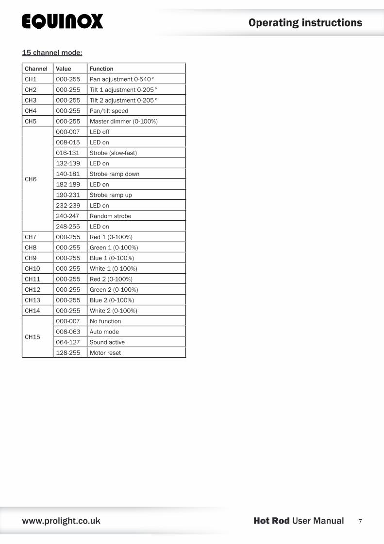
15 channel mode:
Channel Value Function
CH1 000-255 Panadjustment0-540°
CH2 000-255 Tilt1adjustment0-205°
CH3 000-255 Tilt2adjustment0-205°
CH4 000-255 Pan/tiltspeed
CH5 000-255 Masterdimmer(0-100%)
CH6
000-007 LEDoff
008-015 LEDon
016-131 Strobe(slow-fast)
132-139 LEDon
140-181 Stroberampdown
182-189 LEDon
190-231 Stroberampup
232-239 LEDon
240-247 Randomstrobe
248-255 LEDon
CH7 000-255 Red1(0-100%)
CH8 000-255 Green1(0-100%)
CH9 000-255 Blue1(0-100%)
CH10 000-255 White1(0-100%)
CH11 000-255 Red2(0-100%)
CH12 000-255 Green2(0-100%)
CH13 000-255 Blue2(0-100%)
CH14 000-255 White2(0-100%)
CH15
000-007 Nofunction
008-063 Automode
064-127 Soundactive
128-255 Motorreset
Operating instructions
www.prolight.co.uk Hot Rod User Manual 8
Operating instructions
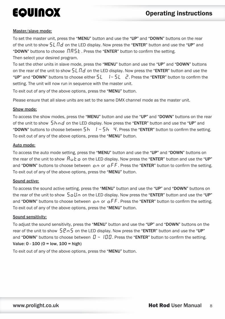
Master/slave mode:
Tosetthemasterunit,pressthe“MENU”buttonandusethe“UP”and“DOWN”buttonsontherearoftheunittoshowSLNd ontheLEDdisplay.Nowpressthe“ENTER”buttonandusethe“UP”and“DOWN”buttonstochooseNast.Pressthe“ENTER”buttontoconfirmthesetting.Thenselectyourdesiredprogram.Tosettheotherunitsinslavemode,pressthe“MENU”buttonandusethe“UP”and“DOWN”buttonsontherearoftheunittoshowSLNdontheLEDdisplay.Nowpressthe“ENTER”buttonandusethe“UP”and“DOWN”buttonstochooseeitherSL 1~SL 2.Pressthe“ENTER”buttontoconfirmthesetting.Theunitwillnowruninsequencewiththemasterunit.
Toexitoutofanyoftheaboveoptions,pressthe“MENU”button.
PleaseensurethatallslaveunitsaresettothesameDMXchannelmodeasthemasterunit.
Show mode:
Toaccesstheshowmodes,pressthe“MENU”buttonandusethe“UP”and“DOWN”buttonsontherearoftheunittoshowShndontheLEDdisplay.Nowpressthe“ENTER”buttonandusethe“UP”and“DOWN”buttonstochoosebetweenSh 1~Sh 4.Pressthe“ENTER”buttontoconfirmthesetting.Toexitoutofanyoftheaboveoptions,pressthe“MENU”button.
Auto mode:
Toaccesstheautomodesetting,pressthe“MENU”buttonandusethe“UP”and“DOWN”buttonsontherearoftheunittoshowAutoontheLEDdisplay.Nowpressthe“ENTER”buttonandusethe“UP”and“DOWN”buttonstochoosebetweenonorofF.Pressthe“ENTER”buttontoconfirmthesetting.Toexitoutofanyoftheaboveoptions,pressthe“MENU”button.
Sound active:
Toaccessthesoundactivesetting,pressthe“MENU”buttonandusethe“UP”and“DOWN”buttonsontherearoftheunittoshowSoUnontheLEDdisplay.Nowpressthe“ENTER”buttonandusethe“UP”and“DOWN”buttonstochoosebetweenonorofF.Pressthe“ENTER”buttontoconfirmthesetting.Toexitoutofanyoftheaboveoptions,pressthe“MENU”button.
Sound sensitivity:
Toadjustthesoundsensitivity,pressthe“MENU”buttonandusethe“UP”and“DOWN”buttonsontherearoftheunittoshowSensontheLEDdisplay.Nowpressthe“ENTER”buttonandusethe“UP”and“DOWN”buttonstochoosebetween0~100.Pressthe“ENTER”buttontoconfirmthesetting.Value: 0 - 100 (0 = low, 100 = high)
Toexitoutofanyoftheaboveoptions,pressthe“MENU”button.
www.prolight.co.uk Hot Rod User Manual 9
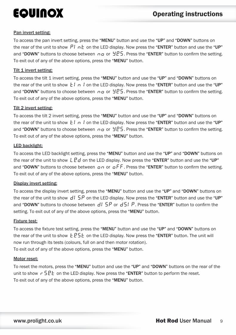
Pan invert setting:
Toaccessthepaninvertsetting,pressthe“MENU”buttonandusethe“UP”and“DOWN”buttonsontherearoftheunittoshowPIntontheLEDdisplay.Nowpressthe“ENTER”buttonandusethe“UP”and“DOWN”buttonstochoosebetweennooryes.Pressthe“ENTER”buttontoconfirmthesetting.Toexitoutofanyoftheaboveoptions,pressthe“MENU”button.
Tilt 1 invert setting:
Toaccessthetilt1invertsetting,pressthe“MENU”buttonandusethe“UP”and“DOWN”buttonsontherearoftheunittoshowtIn1ontheLEDdisplay.Nowpressthe“ENTER”buttonandusethe“UP”and“DOWN”buttonstochoosebetweennooryes.Pressthe“ENTER”buttontoconfirmthesetting.Toexitoutofanyoftheaboveoptions,pressthe“MENU”button.
Tilt 2 invert setting:
Toaccessthetilt2invertsetting,pressthe“MENU”buttonandusethe“UP”and“DOWN”buttonsontherearoftheunittoshowtIn1ontheLEDdisplay.Nowpressthe“ENTER”buttonandusethe“UP”and“DOWN”buttonstochoosebetweennooryes.Pressthe“ENTER”buttontoconfirmthesetting.Toexitoutofanyoftheaboveoptions,pressthe“MENU”button.
LED backlight:
ToaccesstheLEDbacklightsetting,pressthe“MENU”buttonandusethe“UP”and“DOWN”buttonsontherearoftheunittoshowLedontheLEDdisplay.Nowpressthe“ENTER”buttonandusethe“UP”and“DOWN”buttonstochoosebetweenonorofF.Pressthe“ENTER”buttontoconfirmthesetting.Toexitoutofanyoftheaboveoptions,pressthe“MENU”button.
Display invert setting:
Toaccessthedisplayinvertsetting,pressthe“MENU”buttonandusethe“UP”and“DOWN”buttonsontherearoftheunittoshowdIspontheLEDdisplay.Nowpressthe“ENTER”buttonandusethe“UP”and“DOWN”buttonstochoosebetweendISPordSIP.Pressthe“ENTER”buttontoconfirmthesetting.Toexitoutofanyoftheaboveoptions,pressthe“MENU”button.
Fixture test:
Toaccessthefixturetestsetting,pressthe“MENU”buttonandusethe“UP”and“DOWN”buttonsontherearoftheunittoshowtestontheLEDdisplay.Nowpressthe“ENTER”button.Theunitwillnowrunthroughitstests(colours,fullonandthenmotorrotation).Toexitoutofanyoftheaboveoptions,pressthe“MENU”button.
Motor reset:
Toresetthemotors,pressthe“MENU”buttonandusethe“UP”and“DOWN”buttonsontherearoftheunittoshowrsetontheLEDdisplay.Nowpressthe“ENTER”buttontoperformthereset.Toexitoutofanyoftheaboveoptions,pressthe“MENU”button.
Operating instructions
www.prolight.co.uk Hot Rod User Manual 10
Setting the DMX address:
TheDMXmodeenablestheuseofauniversalDMXcontroller.Eachfixturerequiresa“startaddress”from1-512.Afixturerequiringoneormorechannelsforcontrolbeginstoreadthedataonthechannelindicatedbythestartaddress.Forexample,afixturethatoccupiesoruses7channelsofDMXandwasaddressedtostartonDMXchannel100,wouldreaddatafromchannels:100,101,102,103,104,105and106.Chooseastartaddresssothatthechannelsuseddonotoverlap.E.g.thenextunitinthechainstartsat107.
DMX 512:
DMX(DigitalMultiplex)isauniversalprotocolusedasaformofcommunicationbetweenintelligentfixturesandcontrollers.ADMXcontrollersendsDMXdatainstructionsformthecontrollertothefixture.DMXdataissentasserialdatathattravelsfromfixturetofixtureviatheDATA“IN”andDATA“OUT”XLRterminalslocatedonallDMXfixtures(mostcontrollersonlyhaveadata“out”terminal).
DMX linking:
DMXisalanguageallowingallmakesandmodelsofdifferentmanufacturestobelinkedtogetherandoperatefromasinglecontroller,aslongasallfixturesandthecontrollerareDMXcompliant.ToensureproperDMXdatatransmission,whenusingseveralDMXfixturestrytousetheshortestcablepathpossible.TheorderinwhichfixturesareconnectedinaDMXlinedoesnotinfluencetheDMXaddressing.Forexample;afixtureassignedtoaDMXaddressof1maybeplacedanywhereinaDMXline,atthebeginning,attheend,oranywhereinthemiddle.WhenafixtureisassignedaDMXaddressof1,theDMXcontrollerknowstosendDATAassignedtoaddress1tothatunit,nomatterwhereitislocatedintheDMXchain.
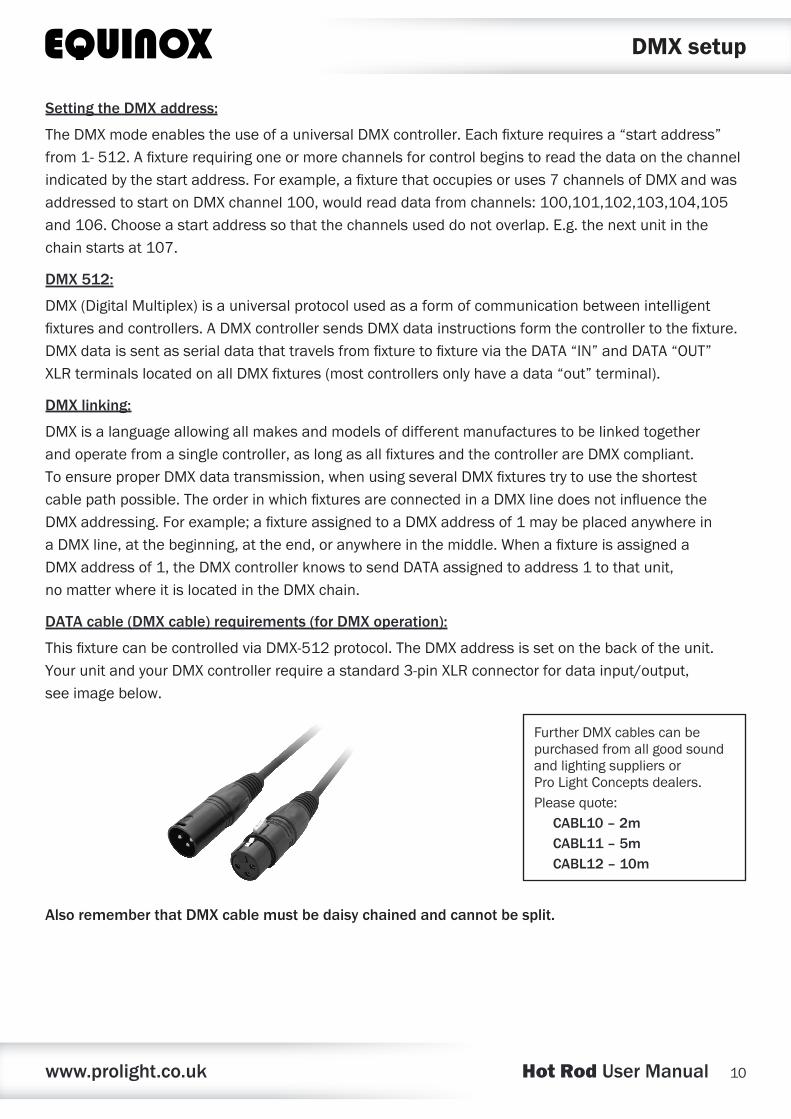
DATA cable (DMX cable) requirements (for DMX operation):
ThisfixturecanbecontrolledviaDMX-512protocol.TheDMXaddressissetonthebackoftheunit.YourunitandyourDMXcontrollerrequireastandard3-pinXLRconnectorfordatainput/output,seeimagebelow.
Also remember that DMX cable must be daisy chained and cannot be split.
DMX setup
FurtherDMXcablescanbepurchasedfromallgoodsoundandlightingsuppliersorProLightConceptsdealers.Pleasequote:
CABL10 – 2mCABL11 – 5mCABL12 – 10m
www.prolight.co.uk Hot Rod User Manual 11
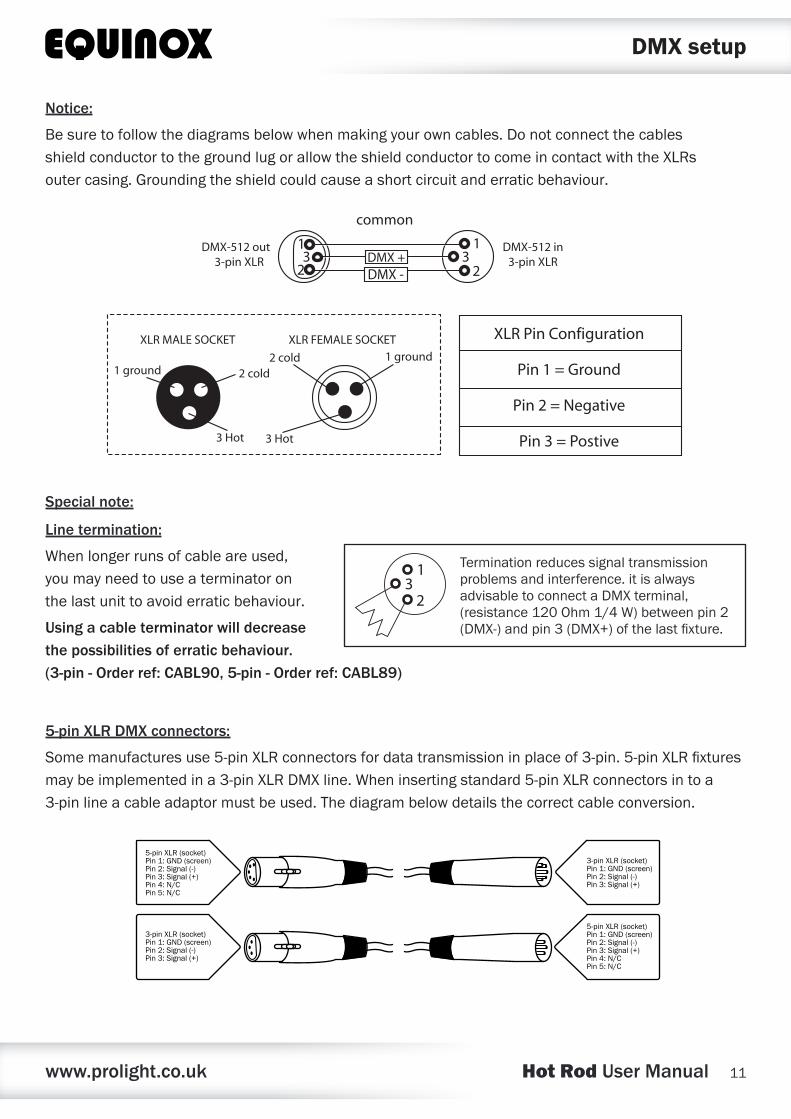
Notice:
Besuretofollowthediagramsbelowwhenmakingyourowncables.DonotconnectthecablesshieldconductortothegroundlugorallowtheshieldconductortocomeincontactwiththeXLRsoutercasing.Groundingtheshieldcouldcauseashortcircuitanderraticbehaviour.
Special note:
Line termination:
Whenlongerrunsofcableareused,youmayneedtouseaterminatoronthelastunittoavoiderraticbehaviour.
Using a cable terminator will decrease the possibilities of erratic behaviour. (3-pin - Order ref: CABL90, 5-pin - Order ref: CABL89)
5-pin XLR DMX connectors:
Somemanufacturesuse5-pinXLRconnectorsfordatatransmissioninplaceof3-pin.5-pinXLRfixturesmaybeimplementedina3-pinXLRDMXline.Wheninsertingstandard5-pinXLRconnectorsintoa3-pinlineacableadaptormustbeused.Thediagrambelowdetailsthecorrectcableconversion.
Terminationreducessignaltransmissionproblemsandinterference.itisalwaysadvisabletoconnectaDMXterminal,(resistance120Ohm1/4W)betweenpin2(DMX-)andpin3(DMX+)ofthelastfixture.
5-pin XLR (socket)Pin 1: GND (screen)Pin 2: Signal (-)Pin 3: Signal (+)Pin 4: N/CPin 5: N/C
3-pin XLR (socket)Pin 1: GND (screen)Pin 2: Signal (-)Pin 3: Signal (+)
3-pin XLR (socket)Pin 1: GND (screen)Pin 2: Signal (-)Pin 3: Signal (+)
5-pin XLR (socket)Pin 1: GND (screen)Pin 2: Signal (-)Pin 3: Signal (+)Pin 4: N/CPin 5: N/C
DMX setup

www.prolight.co.uk Hot Rod User Manual 12
WEEE notice
Correct Disposal of this Product (Waste Electrical & Electronic Equipment)
(Applicable in the European Union and other European countries with separate collection systems)
Thismarkingshownontheproductoritsliterature,indicatesthatitshouldnotbedisposedofwithotherhouseholdwastesattheendofitsworkinglife.Topreventpossibleharmtotheenvironmentorhumanhealthfromuncontrolledwastedisposal,pleaseseparatethisfromothertypesofwastesandrecycleitresponsiblytopromotethesustainablereuseofmaterialresources.
Householdusersshouldcontacteithertheretailerwheretheypurchasedthisproduct,ortheirlocalgovernmentoffice,fordetailsofwhereandhowtheycantakethisitemforenvironmentallysaferecycling.
Businessusersshouldcontacttheirsupplierandcheckthetermsandconditionsofthepurchasecontract.Thisproductshouldnotbemixedwithothercommercialwastesfordisposal.


![[Proposal]Hot Rod Client DOTNET](https://img.pdfslide.us/doc/110x75/55cf9938550346d0339c3f2c/proposalhot-rod-client-dotnet.jpg)