Embed Size (px)
Citation preview
ENMaster Language is English Hot Runner System Installation Guide SVC-17-0001_EN-Rev11RESTRICTED: Property of Synventive. - 43 - All rights reserved. Errors and omissions exceptedFor limited third party distribution based on need and intended use. © 2019 Synventive Molding Solutions
H O T R U N N E R T E C H N O L O G Y
Hot Runner System Installation Guide
Installation of PLUG´N PLAY® HR Systems with Threaded Nozzles
4.5 Installation of PLUG´N PLAY® HR Systems with Threaded Nozzles
Heavy Weight HazardTransport and lifting equipment should be operated only by trained personnel.Operate lifting and transport equipment slowly and carefully to avoid uncontrolled swinging of the manifold.Lifting and transport equipment for lifting Hot Runner Systems shall be approved and properly rated taking into account the weight and size of the manifold.When unpacking the Hot Runner System, there is a risk of injury due to falling parts and sharp edges. Maintain a minimum distance of 1 m from the Hot Runner System.Use personal protective equipment, such as head gear, safety shoes and work gloves.For first aid contact your medical / safety representing.
NOTICEHazard of Material Damage
Without consulting Synventive it is not permitted to do modifications to the hot runner system e.g. geometrical changes to the nozzle tip, except the part shape adjustment in the area of material allowance.Never install or remove the hot runner when the manifold or nozzles are hot, this may cause damage to the nozzles.Move the Hot Runner System only up or down at room temperature 20 °C (68 °F).Always tighten the screws to the torque specified in the respective table in section 13.
The PLUG´N PLAY® hot runner system is supported by thrust pads, center support and positioning dowels. It is not screwed to the cavity plate. The system can be assembled without adjustment. The thrust pads take up the thermal expansion.The following pages reference numbers for the individual parts of the Hot Runner System based on the figure on this page.
Doc003029.png
Parts of the PLUG´N PLAY® Hot Runner System
(1) Insulation plate *(2) Cavity plate *(3) Nozzle tip(4) Center support(5) Spacer plate *(6) Thrust pad(7) Clamping plate *(8) Positioning dowel(9) Center locating ring ** Not included in delivery
ENMaster Language is English Hot Runner System Installation Guide SVC-17-0001_EN-Rev11RESTRICTED: Property of Synventive. - 44 - All rights reserved. Errors and omissions exceptedFor limited third party distribution based on need and intended use. © 2019 Synventive Molding Solutions
H O T R U N N E R T E C H N O L O G Y
Hot Runner System Installation Guide
Installation of PLUG´N PLAY® HR Systems with Threaded Nozzles
4.5.1 Preparation for System Installation
1) Clean the mold cutout and remove metal chips if necessary.
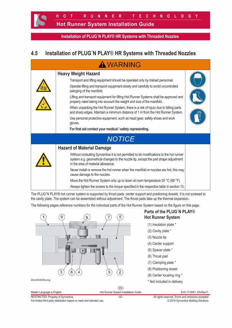
2) Apply plasticine or any other similar substance on the nozzle tip (3).
Doc003034.png
3) Apply a general-purpose grease to the mating surface (d) of the nozzle tip.
Doc003070.png
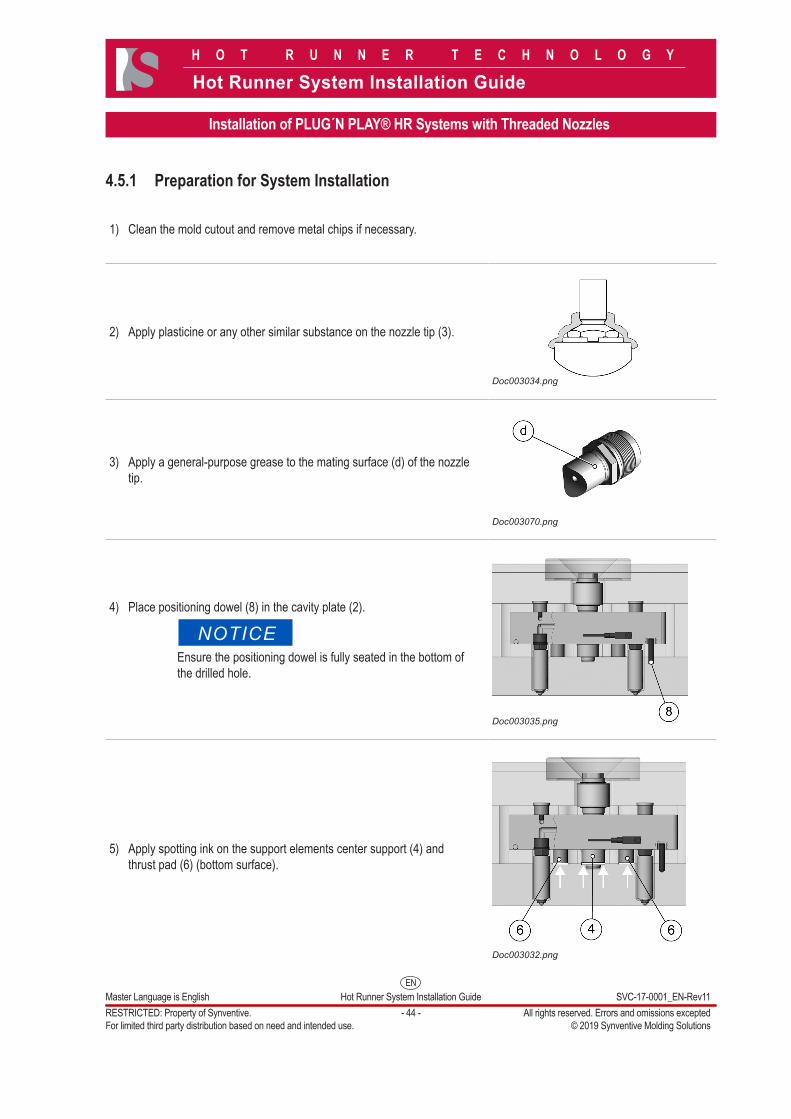
4) Place positioning dowel (8) in the cavity plate (2).
NOTICEEnsure the positioning dowel is fully seated in the bottom of the drilled hole.
Doc003035.png
5) Apply spotting ink on the support elements center support (4) and thrust pad (6) (bottom surface).
Doc003032.png
ENMaster Language is English Hot Runner System Installation Guide SVC-17-0001_EN-Rev11RESTRICTED: Property of Synventive. - 45 - All rights reserved. Errors and omissions exceptedFor limited third party distribution based on need and intended use. © 2019 Synventive Molding Solutions
H O T R U N N E R T E C H N O L O G Y
Hot Runner System Installation Guide
Installation of PLUG´N PLAY® HR Systems with Threaded Nozzles
NOTICEThe following steps have to be done at room temperature 20 ºC (68 ºF).
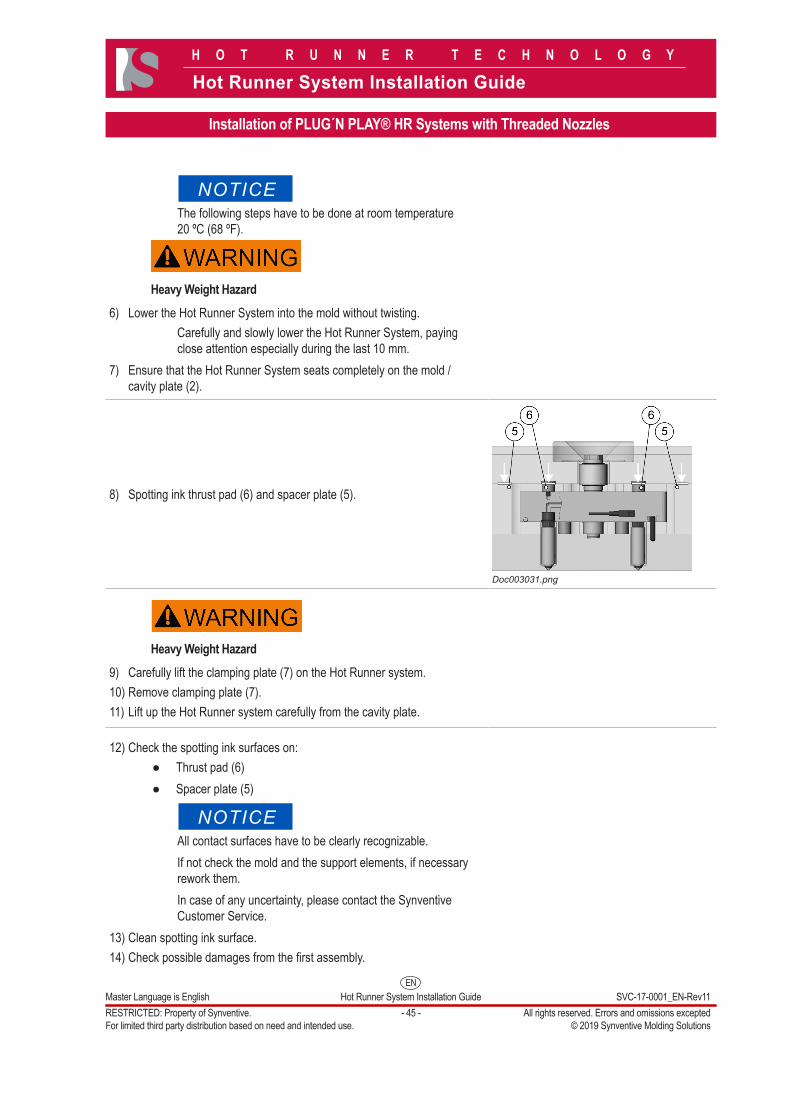
Heavy Weight Hazard6) Lower the Hot Runner System into the mold without twisting.
Carefully and slowly lower the Hot Runner System, paying close attention especially during the last 10 mm.
7) Ensure that the Hot Runner System seats completely on the mold / cavity plate (2).
8) Spotting ink thrust pad (6) and spacer plate (5).
Doc003031.png
Heavy Weight Hazard9) Carefully lift the clamping plate (7) on the Hot Runner system.10) Remove clamping plate (7).11) Lift up the Hot Runner system carefully from the cavity plate.
12) Check the spotting ink surfaces on:●● Thrust pad (6)●● Spacer plate (5)
NOTICEAll contact surfaces have to be clearly recognizable. If not check the mold and the support elements, if necessary rework them.In case of any uncertainty, please contact the Synventive Customer Service.
13) Clean spotting ink surface.14) Check possible damages from the first assembly.
ENMaster Language is English Hot Runner System Installation Guide SVC-17-0001_EN-Rev11RESTRICTED: Property of Synventive. - 46 - All rights reserved. Errors and omissions exceptedFor limited third party distribution based on need and intended use. © 2019 Synventive Molding Solutions
H O T R U N N E R T E C H N O L O G Y
Hot Runner System Installation Guide
Installation of PLUG´N PLAY® HR Systems with Threaded Nozzles
15) Check if the plasticine at the nozzle tip (3) or nozzle is evenly distributed.
NOTICEEnsure there is enough gap between mold and nozzle tip (3). If not rework them.Please note that the distance between mold and nozzle tip (3) will be reduced by thermal expansion while the hot runner is heated up.
16) Remove the plasticine.Doc003030.png
4.5.2 System Installation
NOTICEHazard of Material Damage
Precondition to assembly the system is: ● Applied spotting ink test in the relevant areas. ● Applied plasticine test regarding the nozzle cutouts.
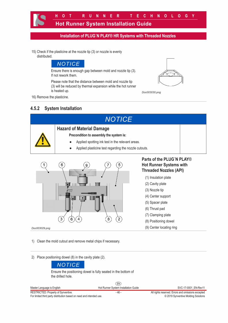
Doc003029.png
Parts of the PLUG´N PLAY® Hot Runner Systems with Threaded Nozzles (API)
(1) Insulation plate(2) Cavity plate(3) Nozzle tip(4) Center support(5) Spacer plate(6) Thrust pad(7) Clamping plate(8) Positioning dowel(9) Center locating ring
1) Clean the mold cutout and remove metal chips if necessary.
2) Place positioning dowel (8) in the cavity plate (2).
NOTICEEnsure the positioning dowel is fully seated in the bottom of the drilled hole.
ENMaster Language is English Hot Runner System Installation Guide SVC-17-0001_EN-Rev11RESTRICTED: Property of Synventive. - 47 - All rights reserved. Errors and omissions exceptedFor limited third party distribution based on need and intended use. © 2019 Synventive Molding Solutions
H O T R U N N E R T E C H N O L O G Y
Hot Runner System Installation Guide
Installation of PLUG´N PLAY® HR Systems with Threaded Nozzles
Heavy Weight Hazard3) Lower the Hot Runner System into the cavity plate without twisting.
NOTICECarefully and slowly lower the Hot Runner System, paying close attention especially during the last 10 mm.
Heavy Weight Hazard4) Carefully lift the clamping plate (7) on the Hot Runner System.
5) Lubricate the thread of the fastening screws (clamping plate / spacer plate / cavity plate) with high-temperature assembly paste (anti-seize compound).
NOTICEThis is an important measure to prevent thread corrosion due to aggressive gases, which could be released during plastics processing.
6) Screw the clamping plate / spacer plate / cavity plate together with the fastening screws.
NOTICEUse torque wrench with wrench insert and the torque specified in the respective table in section 13.
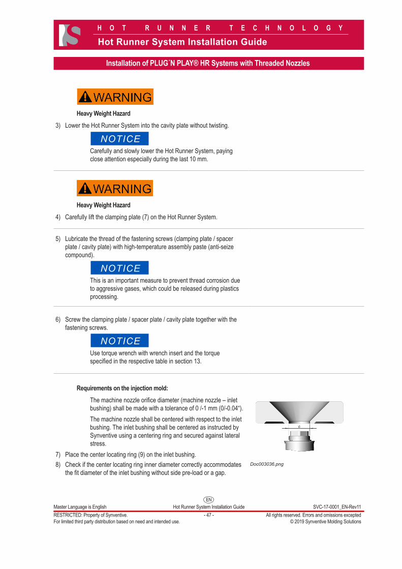
Requirements on the injection mold:The machine nozzle orifice diameter (machine nozzle – inlet bushing) shall be made with a tolerance of 0 /-1 mm (0/-0.04“).The machine nozzle shall be centered with respect to the inlet bushing. The inlet bushing shall be centered as instructed by Synventive using a centering ring and secured against lateral stress.
7) Place the center locating ring (9) on the inlet bushing.8) Check if the center locating ring inner diameter correctly accommodates
the fit diameter of the inlet bushing without side pre-load or a gap.Doc003036.png
ENMaster Language is English Hot Runner System Installation Guide SVC-17-0001_EN-Rev11RESTRICTED: Property of Synventive. - 48 - All rights reserved. Errors and omissions exceptedFor limited third party distribution based on need and intended use. © 2019 Synventive Molding Solutions
H O T R U N N E R T E C H N O L O G Y
Hot Runner System Installation Guide
Installation of PLUG´N PLAY® HR Systems with Threaded Nozzles
9) Lubricate the threads of the center locating ring (9) fastening screws with high-temperature assembly paste (antiseize compound).
NOTICEThis is an important measure to prevent thread corrosion due to aggressive gases, which could be released during plastics processing.
10) Screw the center locating ring (9) together with the clamping plate (7).
NOTICEUse torque wrench with wrench insert and the torque specified in the respective table in section 13.
11) Lubricate the thread of the fastening screws hot half / cavity plate with high-temperature assembly paste (antiseize compound).
12) Bolt together the hot half and the cavity plate.
NOTICEUse torque wrench with wrench insert and the torque specified in the respective table in section 13.
4.5.3 Nozzle Tip AdjustmentIn some cases it is necessary to adjust the nozzle tips to the cutout shape for the injected part. Only nozzle tips with tip extension can be cut. If the nozzle tips with extension are too long, they have to be removed and cut shorter.
Hot Surfaces HazardContact between the skin and the hot injection mold could result in burns.Use personal protective equipment, such as gloves, apron, sleeves and face protection, to guard against burns.
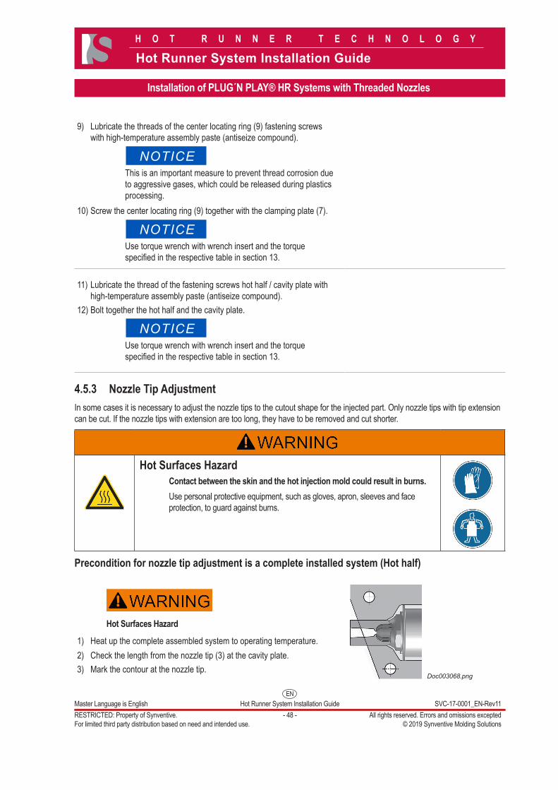
Precondition for nozzle tip adjustment is a complete installed system (Hot half)
Hot Surfaces Hazard
1) Heat up the complete assembled system to operating temperature.2) Check the length from the nozzle tip (3) at the cavity plate.3) Mark the contour at the nozzle tip.
Doc003068.png
ENMaster Language is English Hot Runner System Installation Guide SVC-17-0001_EN-Rev11RESTRICTED: Property of Synventive. - 49 - All rights reserved. Errors and omissions exceptedFor limited third party distribution based on need and intended use. © 2019 Synventive Molding Solutions
H O T R U N N E R T E C H N O L O G Y
Hot Runner System Installation Guide
Installation of PLUG´N PLAY® HR Systems with Threaded Nozzles
NOTICEHazard of Material Damage
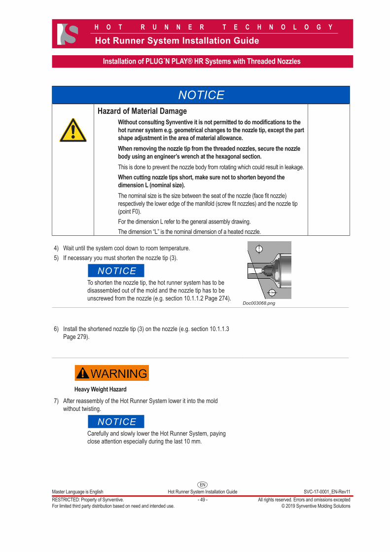
Without consulting Synventive it is not permitted to do modifications to the hot runner system e.g. geometrical changes to the nozzle tip, except the part shape adjustment in the area of material allowance.When removing the nozzle tip from the threaded nozzles, secure the nozzle body using an engineer’s wrench at the hexagonal section.This is done to prevent the nozzle body from rotating which could result in leakage.When cutting nozzle tips short, make sure not to shorten beyond the dimension L (nominal size).The nominal size is the size between the seat of the nozzle (face fit nozzle) respectively the lower edge of the manifold (screw fit nozzles) and the nozzle tip (point F0). For the dimension L refer to the general assembly drawing.The dimension “L” is the nominal dimension of a heated nozzle.
4) Wait until the system cool down to room temperature.5) If necessary you must shorten the nozzle tip (3).
NOTICETo shorten the nozzle tip, the hot runner system has to be disassembled out of the mold and the nozzle tip has to be unscrewed from the nozzle (e.g. section 10.1.1.2 Page 274).
Doc003068.png
6) Install the shortened nozzle tip (3) on the nozzle (e.g. section 10.1.1.3 Page 279).
Heavy Weight Hazard 7) After reassembly of the Hot Runner System lower it into the mold
without twisting.
NOTICECarefully and slowly lower the Hot Runner System, paying close attention especially during the last 10 mm.
ENMaster Language is English Hot Runner System Installation Guide SVC-17-0001_EN-Rev11RESTRICTED: Property of Synventive. - 50 - All rights reserved. Errors and omissions exceptedFor limited third party distribution based on need and intended use. © 2019 Synventive Molding Solutions
H O T R U N N E R T E C H N O L O G Y
Hot Runner System Installation Guide
Installation of PLUG´N PLAY® HR Systems with Threaded Nozzles
8) Lubricate the thread of the fastening screws (clamping plate / spacer plate / cavity plate ) with high-temperature assembly paste (anti-seize compound).
NOTICEThis is an important measure to prevent thread corrosion due to aggressive gases, which could be released during plastics processing.
9) Bolt together the clamping plate / spacer plate / cavity plate with the fastening screws.
NOTICEMeet the prescribed torque values and use high-temperature assembly paste for the threads.
10) Remove all guiding elements if used.
Hot Surfaces Hazard11) Heat the hot runner to normal operating temperature.12) Contour the nozzle tip to the cavity if required.
13) Machine the contour of the nozzle tip when nozzle is installed in the cavity.
14) In the case where the final contour needs to be placed on the valve pin, the valve pin must be rounded at the adjusted area also.
NOTICEGenerally only tips with extension are allowed to be contoured.
Heavy Weight Hazard15) Install the clamping plate (7) and the insulation plate (1).16) Lubricate the thread of the insulation plate (1) / clamping plate (7)
screws with high-temperature assembly paste (antiseize compound).
NOTICEThis is an important measure to prevent thread corrosion due to aggressive gases, which could be released during plastics processing.
ENMaster Language is English Hot Runner System Installation Guide SVC-17-0001_EN-Rev11RESTRICTED: Property of Synventive. - 51 - All rights reserved. Errors and omissions exceptedFor limited third party distribution based on need and intended use. © 2019 Synventive Molding Solutions
H O T R U N N E R T E C H N O L O G Y
Hot Runner System Installation Guide
Installation of PLUG´N PLAY® HR Systems with Threaded Nozzles
17) Screw the insulation plate (1) and the clamping plate (7) together.
NOTICEUse torque wrench with wrench insert and the torque specified in the respective table in section 13.
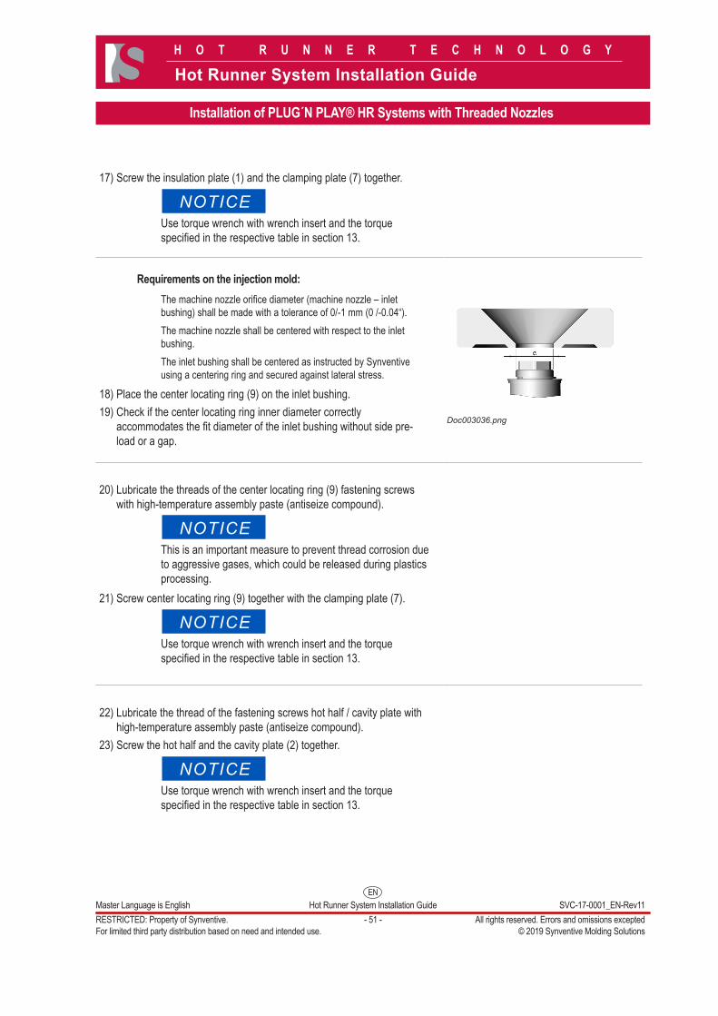
Requirements on the injection mold:The machine nozzle orifice diameter (machine nozzle – inlet bushing) shall be made with a tolerance of 0/-1 mm (0 /-0.04“).The machine nozzle shall be centered with respect to the inlet bushing. The inlet bushing shall be centered as instructed by Synventive using a centering ring and secured against lateral stress.
18) Place the center locating ring (9) on the inlet bushing.19) Check if the center locating ring inner diameter correctly
accommodates the fit diameter of the inlet bushing without side pre-load or a gap.
Doc003036.png
20) Lubricate the threads of the center locating ring (9) fastening screws with high-temperature assembly paste (antiseize compound).
NOTICEThis is an important measure to prevent thread corrosion due to aggressive gases, which could be released during plastics processing.
21) Screw center locating ring (9) together with the clamping plate (7).
NOTICEUse torque wrench with wrench insert and the torque specified in the respective table in section 13.
22) Lubricate the thread of the fastening screws hot half / cavity plate with high-temperature assembly paste (antiseize compound).
23) Screw the hot half and the cavity plate (2) together.
NOTICEUse torque wrench with wrench insert and the torque specified in the respective table in section 13.
ENMaster Language is English Hot Runner System Installation Guide SVC-17-0001_EN-Rev11RESTRICTED: Property of Synventive. - 52 - All rights reserved. Errors and omissions exceptedFor limited third party distribution based on need and intended use. © 2019 Synventive Molding Solutions
H O T R U N N E R T E C H N O L O G Y
Hot Runner System Installation Guide
Installation of PLUG´N PLAY® HR Systems with Threaded Nozzles
4.5.4 For non pre-wired Systems
Danger to Life by Electric ShockSerious personal injury or death can result from electrical contact.Power supply should only be connected by properly trained and qualified personnel.Verify that all power source connections are properly grounded (proceed as described in section 5.2).For first aid contact your medical / safety representing.
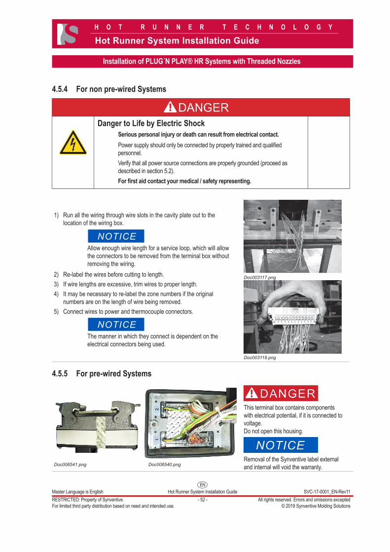
1) Run all the wiring through wire slots in the cavity plate out to the location of the wiring box.
NOTICEAllow enough wire length for a service loop, which will allow the connectors to be removed from the terminal box without removing the wiring.
2) Re-label the wires before cutting to length.3) If wire lengths are excessive, trim wires to proper length.4) It may be necessary to re-label the zone numbers if the original
numbers are on the length of wire being removed.5) Connect wires to power and thermocouple connectors.
NOTICEThe manner in which they connect is dependent on the electrical connectors being used.
Doc003117.png
Doc003118.png
4.5.5 For pre-wired Systems
Doc006541.png Doc006540.png
This terminal box contains components with electrical potential, if it is connected to voltage. Do not open this housing.
Removal of the Synventive label external and internal will void the warranty.