Embed Size (px)
Citation preview
HOT Lane Buffer and Mid-Point Access Design Review Report October 2006
Prepared for the
Washington State Department of Transportation and in cooperation with
U.S. Department of Transportation Federal Highway Administration
HOT/HOV Lane Buffer and Mid-Point Access Oct. 2006 Design Guidance Report TOC-i
HOT/HOV Lane Buffer and Mid-Point Access Oct. 2006 Design Guidance Report TOC-ii
1. REPORT NO. 2. GOVERNMENT ACCESSION NO. 3. RECIPIENT'S CATALOG NO.
WA-RD 651.1
4. TITLE AND SUBTITLE 5. REPORT DATE
HOT Lane Buffer and Mid-Point Access Design Review Report October 2006 6. PERFORMING ORGANIZATION CODE 7. AUTHOR(S) 8. PERFORMING ORGANIZATION REPORT NO.
Carter Burgess in association with Wilbur Smith Associates; The Resource Group; Perteet; EnviroIssues; IBI Group; Demich Consulting 9. PERFORMING ORGANIZATION NAME AND ADDRESS 10. WORK UNIT NO.
Carter Burgess 1420 Fifth Avenue, Suite 2200 11. CONTRACT OR GRANT NO.
Seattle, WA 98101
12. SPONSORING AGENCY NAME AND ADDRESS 13. TYPE OF REPORT AND PERIOD COVERED
Washington State Department of Transportation Planning and Programming Service Center, Research Office
Research, Spring 2006 with a September 2006 update
Olympia, Washington 98504-7370 14. SPONSORING AGENCY CODE
Washington State Dept. of Transportation 15. SUPPLEMENTARY NOTES
This study was conducted in cooperation with the U.S. Department of Transportation, Federal Highway Administration. 16. ABSTRACT
The purpose of this report is to provide an overview of buffer and midpoint access designs for concurrent flow, high occupancy toll (HOT) lanes that are either in operation or under study and recommended the preferred buffer and access designs for these facilities. HOT lanes are dedicated to transit, carpools and vanpools, but also allow solo drivers to use the facility for a toll when surplus capacity is available. With the application of a HOT lane facility, a single occupant vehicle (SOV) can choose to pay for the use of the surplus capacity in the lanes. Tolls are adjusted to assure that these lanes keep flowing even when the regular lanes are congested. The primary tasks completed for this report include:
• Research on non-barrier-separated designs, locations and designs for access points, and enforcement measures through a literature review and survey of other state agency HOT and /or HOV lane designs;
• Evaluation of the various design options including safety, cost, and performance; and
• Documentation of the findings and design recommendations for future HOT lane facilities in the state of Washington.
Based on the information gathered from existing and planned concurrent traffic flow, high occupancy vehicle (HOV) or HOT facilities, this report provides presents the following recommendations:
• A preferred buffer width between a HOT lane and an adjacent general purpose lane of 4 feet, with a minimum recommended width of 2 feet if it is not feasible to provide a 4 foot buffer.
• A continuous inside shoulder of 14 feet for enforcement and to serve as a breakdown lane, with a minimum 2-foot inside shoulder recommended to separate the travel lane from any barrier if the ideal width is not feasible.
• Mid-point access location openings of 1,000 feet per lane change; with a minimum length of 500 feet. For a combined access (allowing both ingress and egress), the length of the access point should be at least 1,000 feet (twice the minimum acceptable lane change distance of 500 feet).
17. KEY WORDS 18. DISTRIBUTION STATEMENT
High occupancy toll lanes, HOT lanes, buffers, access, median, barriers, high occupancy vehicles, tolls, pricing, State Route 167, Seattle
No restrictions. This document is available to the public through the National Technical Information Service, Springfield, VA 22616
19. SECURITY CLASSIF. (of this report) 20. SECURITY CLASSIF. (of this page) 21. NO. OF PAGES 22. PRICE
None None N/A
HOT/HOV Lane Buffer and Mid-Point Access Oct. 2006 Design Guidance Report TOC-iii
DISCLAIMER
The contents of this report reflect the views of the authors, who are responsible for the facts and the accuracy of the data presented herein. The contents do not necessarily reflect the official views or policies of the Washington State Department of Transportation or the Federal Highway Administration. This report does not constitute a standard, specification, or regulation.
HOT/HOV Lane Buffer and Mid-Point Access Oct. 2006 Design Guidance Report TOC-iv
TABLE OF CONTENTS
Executive Summary....................................................................................................................1
1. Introduction ..........................................................................................................................1-1 1.1 How are HOT lanes different from HOV lanes?...............................................................1-1 1.2 How are the lanes physically managed? .........................................................................1-1 1.3 What is the purpose of this report? ..................................................................................1-2 1.4 What is contained in this report?......................................................................................1-2
2. Overview of Existing Programs and research ..................................................................2-1 2.1 Literature Review .............................................................................................................2-1 2.2 Agency Interviews............................................................................................................2-2
3. Design Guidance..................................................................................................................3-4 3.1 Cross-Section Design ......................................................................................................3-4 3.2 Buffer Separation from General Purpose (GP) lanes ......................................................3-6 3.3 Access Points ................................................................................................................3-13 3.4 Enforcement...................................................................................................................3-20
4. Recommendations.............................................................................................................4-27 4.1 Buffer and Inside Shoulder Width ..................................................................................4-27 4.2 Access Point Location....................................................................................................4-27 4.3 Access Point Length ......................................................................................................4-27 4.4 Access Point Design ......................................................................................................4-28 4.5 Final Considerations ......................................................................................................4-28
LIST OF EXHIBITS- Exhibit 3-1 Median-Based Concurrent Flow HOT Cross-sections .......................................3-8 Exhibit 3-2 Alternative HOT Lane Slip Ramp Configuration ..............................................3-14 Exhibit 3-3 Long Island Expressway Ingress Point ............................................................3-15 Exhibit 3-4 Long Island Expressway Access Striping ........................................................3-16 Exhibit 3-5 Ingress/Egress Access for Concurrent Flow HOV Lanes ................................3-17 Exhibit 3-6 Weave Distance at Buffer—Separated HOV Facilities ....................................3-18 Exhibit 3-7 Examples of Cross-sections for Enforcement Areas along concurrent Flow and
Exclusive Buffer-Separated Managed Lanes .................................3-23 Exhibit 3-8 Examples of Directional and Bi-Directional Enforcement Area Layouts ..........3-24 LIST OF TABLES Summary Table 3-1 HOT Lane Cross-Section Design Standards.......................................3-6 Summary Table 3-2 Example Design Adjustments for Concurrent Flow Managed Lanes
Facilities............................................................................................3-9 Summary Table 3-3 Advantages and Disadvantages of Buffer Separation with Limited
Access Versus Unlimited Access ...................................................3-12 Summary Table 3-4 Weaving Distances for Managed Lane Cross-Freeway Maneuvers ities
........................................................................................................3-19 Summary Table 3-5 General Enforcement Information ......................................................3-25 LIST OF APPENDICES Appendix A: References Appendix B: Summary of Reports Appendix C: Summary of Agency Interviews
HOT/HOV Lane Buffer and Mid-Point Access Oct. 2006 Design Guidance Report TOC-v
EXECUTIVE SUMMARY
i. WHAT IS THE PURPOSE OF THIS REPORT?
The purpose of this report is to provide an overview of buffer and midpoint access designs for concurrent flow, high occupancy toll (HOT) lanes that are either in operation or under study and to recommend the preferred buffer and access designs for these facilities.
HOT lanes are dedicated to transit, carpools and vanpools, but also allow solo drivers to use the facility for a toll when surplus capacity is available. With the application of a HOT lane facility, a single occupant vehicle (SOV) can choose to pay for the use of the surplus capacity in the lanes. Tolls are adjusted to ensure that these lanes keep flowing even when the regular lanes are congested.
The primary tasks completed to prepare this report include:
• Research on non-barrier-separated designs, locations and designs for access points, and enforcement measures through a literature review and survey of other state agency HOT and /or HOV lane designs;
• Evaluation of the various design options including safety, cost, and performance; and
• Documentation of the findings and design recommendations for future HOT lane facilities in the state of Washington.
Based on the information gathered from existing and planned concurrent traffic flow, high occupancy vehicle (HOV) or HOT facilities, this report provides presents the following recommendations:
• A preferred buffer width between a HOT lane and an adjacent general purpose lane of 4 feet, with a minimum recommended width of 2 feet if it is not feasible to provide a 4 foot buffer.
• A continuous inside shoulder of 14 feet for enforcement and to serve as a breakdown lane, with a minimum 2-
HOT/HOV Lane Buffer and Mid-Point Access Oct. 2006 Design Guidance Report ES-1
foot inside shoulder recommended to separate the travel lane from any barrier if the ideal width is not feasible.
Mid-point access location openings of 1,000 feet per lane change; with a minimum length of 500 feet. For a combined access (allowing both ingress and egress), the length of the access point should be at least 1,000 feet (twice the minimum acceptable lane change distance of 500 feet).
The findings and recommendations presented in this report may be considered for the design of the SR 167 HOT Lanes project and future HOT facilities in Washington state.
HOT/HOV Lane Buffer and Mid-Point Access Oct. 2006 Design Guidance Report ES-2
1. INTRODUCTION
The Washington State Department of Transportation (WSDOT) has recently engaged in several studies to evaluate High Occupancy Vehicle (HOV) lanes and their potential conversion to High Occupancy Toll (HOT) lanes in the central Puget Sound region. The culmination of these studies was the authorization and funding of the SR 167 HOT Lanes Pilot Project, the first in Washington State . This project is a four-year pilot program that will test the benefits of implementing HOT lanes in one corridor to help determine how and where additional HOT lanes can be implemented.
1.1
1.2
HOW ARE HOT LANES DIFFERENT FROM HOV LANES?
HOV lanes are an effective way to improve the overall person-moving capacity of a roadway. Typically a dedicated travel lane is provided within existing roadway right-of-way for the exclusive use of buses and other HOVs. HOT lanes are similar to HOV lanes – they are dedicated to transit, carpools and vanpools, but also allow solo drivers to use the facility for a toll fee. A single occupant vehicle (SOV) can choose to pay for the use of the surplus capacity in the HOT lanes. Tolls are adjusted to ensure that these lanes keep flowing even when the regular lanes are congested.
HOW ARE HOT LANES PHYSICALLY MANAGED?
HOT lanes are physically managed by creating buffers and/or barriers and access restrictions along the roadway. There are a number of functioning HOT lane programs throughout the country, which use various management techniques. Research studies also provide guidance on the best ways to manage lanes. This SR 167: HOT Buffer and Mid-Point Access Design
HOT/HOV Lane Buffer and Mid-Point Access Oct. 2006 Design Guidance Report 1-1

Review Report provides a summary of these existing programs and research reports.
1.3
1.4
WHAT IS THE PURPOSE OF THIS REPORT?
The purpose of this report is to provide an overview of buffer and midpoint access designs for concurrent flow, high occupancy toll (HOT) lanes that are either in operation or under study and to recommend the preferred buffer and access designs for these facilities.
The primary tasks completed to prepare this report include:
Research on non-barrier-separated designs, locations and designs for access points, and enforcement measures through a literature review and survey of other state agency HOT lane designs;
Evaluation of the various design options including safety, cost, and performance; and
Documentation of the findings and design recommendations for the SR 167 project as well as future HOT lane facilities in the state of Washington.
Prior to the initiation of this study, WSDOT began the research effort by contacting other agencies and requesting information regarding the other agencies’ HOT lanes. Specifically, WSDOT inquired about how the lanes were physically constructed, striped, and signed, as well as how the lanes were managed. The project team’s research builds on this effort by documenting the information received from other state agencies, describing the methodology used, evaluating these different methods, and providing a design guidance document for WSDOT.
WHAT IS CONTAINED IN THIS REPORT?
The project effort, as documented in this report, began with the project team contacting six transportation agencies that are currently planning, designing, constructing or operating HOT/HOV lane facilities.
In addition, literature regarding HOT lane design was reviewed. Chapter 2 provides an overview of this research.
HOT/HOV Lane Buffer and Mid-Point Access Oct. 2006 Design Guidance Report 1-2
Agencies across the United States were contacted with six agencies being interviewed in person or over the telephone (with multiple representatives being interviewed depending on how responsibilities for the HOT lanes were divided in the organization). The agencies interviewed included:
Minnesota Department of Transportation (MnDOT)
Colorado Department of Transportation (CDOT)
Orange County Transportation Authority (OCTA)
California Department of Transportation (Caltrans)
Texas Department of Transportation (TxDOT)
New York State Department of Transportation (NYSDOT).
Chapter 3 provides specific examples of design guidance and discusses relevant design issues such as separation, access control, safety, and enforcement on HOT facilities. Chapter 4 presents a summary of findings.
HOT/HOV Lane Buffer and Mid-Point Access Oct. 2006 Design Guidance Report 1-3
2. OVERVIEW OF EXISTING PROGRAMS AND RESEARCH
The research conducted for this study included a literature review and interviews with agencies in the latter stages of planning or that are currently operating HOT lane facilities. Appendices A through C provide the complete interviews, findings, and conclusions from this research effort. The following provides an overview of the research findings.
2.1 LITERATURE REVIEW
An extensive literature review was conducted to determine the current thinking on HOT lanes, and to develop an understanding of what current studies suggest in terms of safety, operation, separation design, and access design for HOT/HOV facilities. A list of references is located in Appendix A.
When reviewing existing research, the project team identified six reports which provided significant guidance for HOT lane design. These six reports were:
Weave Analysis and Performance: The Washington State Case Study, October 2001
Interim Managed Lane Manual, October 2003
Crash Data Identify Safety Issues for High Occupancy Vehicle Lanes in Selected Texas Corridors, 2004. Project Summary Report. 04434S
HOT/HOV Lane Buffer and Mid-Point Access Oct. 2006 Design Guidance Report 2-1
A Guide for HOT Lane Development; Report FHWA-OP-03-009, US Department of Transportation, Federal Highway Administration, 2003
Caltrans High Occupancy Vehicle (HOV) Guidelines, California Department of Transportation, 2003
HOV Systems Manual, National Cooperative Highway Research Program (NCHRP) Report 414, Transportation Research Board, National Research Council, 1998
Information from these documents was used to develop guidelines and design proposals for the SR 167 HOT lanes project. They are referenced throughout Chapter 3 of this document, and are also summarized in Appendix B.
2.2 AGENCY INTERVIEWS
The project team contacted a number of state departments of transportation (DOT) and other public agencies that are actively planning, designing, constructing, or operating HOT and /or HOV facilities. The agencies contacted include:
Minnesota Department of Transportation (MnDOT)
Colorado Department of Transportation (CDOT)
Orange County Transportation Authority (OCTA)
California Department of Transportation (Caltrans)
Texas Department of Transportation (TxDOT)
New York State Department of Transportation (NYSDOT).
Information was obtained by conducting telephone interviews with key personnel from each of these state DOTs.
The results of the interviews indicate that when making design decisions, most agencies began their managed lane projects with a review of the current literature for standard guidance on managed lane facilities. This literature typically includes the Federal Highway Administration’s Guide for HOT Lane
HOT/HOV Lane Buffer and Mid-Point Access Oct. 2006 Design Guidance Report 2-2
Development, the National Cooperative Highway Research Program (NCHRP) Report 414 High Occupancy Vehicle (HOV) Systems Manual, Caltrans High Occupancy Vehicle Guidelines, and others. The agencies then network amongst themselves to determine any “lessons learned” and other specific design considerations for which the contacted agencies accounted. The surveyed agencies have typically applied the accepted standards as best they can to their specific corridor. HOT lanes are most often HOV to HOT lane conversions such as I-10 Katy Freeway in Houston. Because of right-of-way and funding constraints, the surveyed agencies were often not able to provide the most desirable design guidelines. No contemporary cases of general purpose lanes being converted to HOV or HOT lane use were found.
Appendix C provides a summary of findings from these interviews.
HOT/HOV Lane Buffer and Mid-Point Access Oct. 2006 Design Guidance Report 2-3
3. DESIGN GUIDANCE
This chapter addresses some of the major design issues related to HOT lane facilities. The design considerations addressed here are limited to physical features focused specifically on buffer and access design, and providing sufficient facilities for enforcement. .
This chapter provides an overview of current practice for HOT lane design. Presented in this chapter is information regarding:
General roadway cross-section design
Buffer separation from general purpose lanes (ideal, acceptable, and minimum standards)
Other separation options (flexible and rigid barriers)
Access points—design (including length and location)
Access points—enforcement
In addition to current practices, recommendations are also presented for each of these roadway elements.
3.1 CROSS-SECTION DESIGN OPTIONS
The cross-section design of the various existing HOT lane facilities in the United States are not consistent. Recommended design standards, guidelines, and specifications are available for HOV facilities from the Federal Highway Administration, NCHRP, several state DOTs, and various local governments. They all tend to be minor variations of the same theme (refer to Table 3-1, Exibit 3-1, and Exibit 3-2 for examples of recommended cross-sections).
HOT/HOV Lane Buffer and Mid-Point Access Oct. 2006 Design Guidance Report 3-4
While recommended specifications and procedures exist for HOV facilities, the concept of HOT lane facilities is relatively new and design standards adopted for various HOT lane elements are similar to HOV facilities except for access control requirements, toll collection facilities and enforcement.
As shown in Summary Table 3-1, the basic cross-section requirements of HOT lanes are similar to those of general purpose and HOV lanes. Similar to most HOV lanes, HOT lanes have been placed in or adjacent to the median of an existing highway. The development of additional lane capacity within existing highway corridors inevitably requires extensive retrofitting and often does not allow desired standards to be achieved throughout the length of the corridor. When this is the case, adjustments to the standards need to be assessed on a case by case basis.
Note:
While reviewing this design information, the project team observed an inconsistency in how lane widths and buffer widths are generally described. Lane widths are typically described from center of striping to center of striping. Buffer widths in contrast tend to be measured from outside edge of buffer striping to outside edge of buffer striping. While recognizing this discrepancy, for consistency in this report the existing conventions will be used. Existing conventions are:
All travel-lane widths will be described from center of lane striping to center of lane striping. In other words, three twelve-foot lanes total 36 feet wide, not 36 feet plus the lane stripe widths.
Buffer widths will be described from edge of buffer striping to edge of buffer striping. For example, a 2-foot buffer could be an 8-inch stripe, 8-inch gap, and another 8-inch stripe, creating a 24-inch (2-foot) buffer
HOT/HOV Lane Buffer and Mid-Point Access Oct. 2006 Design Guidance Report 3-5
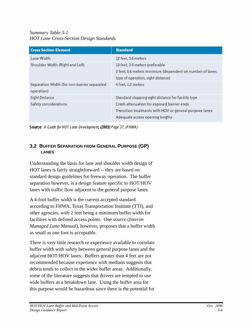
Summary Table 3-1
Source: A Guide for HOT Lane Development, (2003) Page
HOT Lane Cross-Section Design Standards
37, (FHWA)
.2 BUFFER SEPARATION FROM GENERAL PURPOSE (GP)
Understanding the basis for lane and shoulder width design of
ffer
I), and
idth
ience available to correlate
r
3LANES
HOT lanes is fairly straightforward -- they are based on standard design guidelines for freeway operation. The buseparation however, is a design feature specific to HOT/HOV lanes with traffic flow adjacent to the general purpose lanes.
A 4-foot buffer width is the current accepted standard according to FHWA, Texas Transportation Institute (TTother agencies, with 2 feet being a minimum buffer width for facilities with defined access points. One source (Interim Managed Lane Manual), however, proposes that a buffer was small as one foot is acceptable.
There is very little research or experbuffer width with safety between general purpose lanes and the adjacent HOT/HOV lanes. Buffers greater than 4 feet are not recommended because experience with medians suggests that debris tends to collect in the wider buffer areas. Additionally, some of the literature suggests that drivers are tempted to use wide buffers as a breakdown lane. Using the buffer area for this purpose would be hazardous since there is the potential fo
HOT/HOV Lane Buffer and Mid-Point Access Oct. 2006 Design Guidance Report 3-6
high speed traffic on both sides of the buffer area. While the 4-foot buffer seems to be an accepted maximum, and the caution exhibited in not wanting to provide an unsafe “refuge” is intuitively obvious, no research or specific experience wasfound regarding driver behavior and use of buffers wider thafeet.
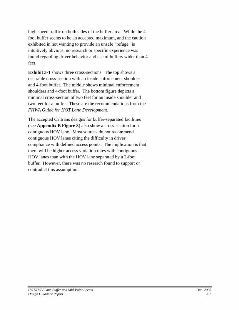
Exhib
n 4
it 3-1 shows three cross-sections. The top shows a r
nd e
arated facilities
ion is that
r
desirable cross-section with an inside enforcement shouldeand 4-foot buffer. The middle shows minimal enforcement shoulders and 4-foot buffer. The bottom figure depicts a minimal cross-section of two feet for an inside shoulder atwo feet for a buffer. These are the recommendations from thFHWA Guide for HOT Lane Development.
The accepted Caltrans designs for buffer-sep(see Appendix B Figure 3) also show a cross-section for a contiguous HOV lane. Most sources do not recommend contiguous HOV lanes citing the difficulty in driver compliance with defined access points. The implicatthere will be higher access violation rates with contiguous HOV lanes than with the HOV lane separated by a 2-foot buffer. However, there was no research found to support ocontradict this assumption.
HOT/HOV Lane Buffer and Mid-Point Access Oct. 2006 Design Guidance Report 3-7
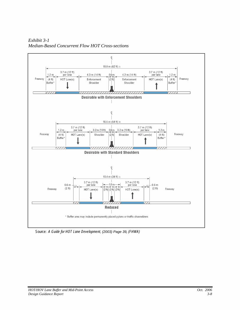
Exhibit 3-1 Median-Based Concurrent Flow HOT Cross-sections
Source: A Guide for HOT Lane Development, (2003) Page 39, (FHWA)
HOT/HOV Lane Buffer and Mid-Point Access Oct. 2006 Design Guidance Report 3-8
In addition to Exhibit 3-1 depicting buffer-separated facilities, the Interim Managed Lane Manual provides the following (Summary Table 3-2) prioritized listing of design compromises, should existing conditions prohibit the construction of the ideal cross-section.
Summary Table 3-2 Example Design Adjustments for Concurrent Flow Managed Lanes Facilities Ordered Sequence Cross-Section Design Change
First Reduce left managed lane lateral clearance to no less than 2 ft (0.6 m). Second Reduce freeway right lateral clearance (shoulder) from 10 ft (3.0 m) to no less
than 8 ft (2.4 m). Third Reduce buffer separation to no less than 1 ft (0.3m). Fourth Reduce managed lane width to no less than 11 ft (3.3 m). (Some agencies
prefer reversing fourth and fifth steps when busses are projected to use the managed lane facility.)
Fifth Reduce selected mixed-flow lane widths to no less than 11 ft (3.3 m). (Leave at least one 12-ft (3.6 m) outside lane for trucks.)
Sixth Reduce freeway right lateral clearance shoulder from 8 ft (2.4 m) to no less than 4 ft (1.2 m).
Seventh Transition barrier shape at columns to vertical face or remove buffer separation between the managed lane and the mixed-flow lanes.
Source: Interim Managed Lane Manual (2003) Page 4-28 (TTI, FHWA, TxDOT)
3.2.1
3.2.2
Recommended Buffer Cross Section
Research results indicate that buffers can range in width and cross section depending upon the existing roadway configuration. The following section presents the project team’s findings for the ideal situation, as well as preferred and minimum buffer cross sections.
Ideal Buffer-Separated Cross Section
As a result of the research done for this study, the project team recommends that the ideal buffer-separated cross-section include a 4-foot buffer with a 14-foot inside shoulder (to be used as an enforcement lane). Under this configuration, the HOT lanes can shift onto the shoulder at designated access points in order to provide an auxiliary lane to be used as acceleration or deceleration lane for separated access points or a weave lane for combined access points.
HOT/HOV Lane Buffer and Mid-Point Access Oct. 2006 Design Guidance Report 3-9
Providing a supplemental lane allows for the separation of weaving movements from the general purpose lane and the HOT lane. Removing the weave from the HOT lane allows for more consistent speeds in the lane. The draw back of this approach is that a vehicle moving from one lane to the other has to merge twice; once into the weaving lane and again into the destination lane. Separating the ingress and egress points to the HOT lane can eliminate the second weave maneuver. In a separated access design, drivers only have to exit their current traffic lane, change speed as appropriate in the acceleration/ deceleration lane and then merge into the destination lane.
Separate auxiliary lanes at the access points can be provided with the smaller buffer widths in a manner similar to the ideal buffer width described above. To accomplish this, the travel lanes need to use the width of the inside shoulder and, if necessary the outside shoulder to flare out to create adequate width for the auxiliary lane.
3.2.3 Acceptable Buffer Width
An acceptable buffer design consists of a 2-foot to 4-foot wide striped buffer. The standard acceptable buffer width as outlined in the FHWA Guide for HOT Lane Development is four feet with a minimum of two feet.
September 2006 Update
According to a recent TTI report, previous studies regarding the safety of concurrent flow, buffer separated HOV and/or HOT lane facilities regarding safety “have been relatively inconclusive. Some studies have concluded that buffer-separated concurrent flow lanes are as safe as other types of HOV lane projects, while others have indicated a safety concern with these types of projects”.
The same report cites an increase in injury crash rates since installation of buffer separated HOV lanes on two corridors in Dallas, Texas. The report cites that increases in injury crashes was likely due to the speed differential between HOV lanes and
HOT/HOV Lane Buffer and Mid-Point Access Oct. 2006 Design Guidance Report 3-10
the general-purpose lanes. [TTI Crash Data Identify Safety Issues for High-Occupancy Vehicle Lanes in Selected Texas Corridors, 2004. Project Summary Report 04434S]
In contrast, a section of the Interstate 394 (I-394) in Minneapolis, Minnesota recently converted its concurrent flow HOV lanes to HOT facilities with a two foot buffer separation between the HOT lanes and adjacent general purpose lanes. The HOT lanes include multiple mid-point access locations. Since opening the facility in May 2005, the I-394 HOT lanes have not experienced an increase in accidents within this corridor – in fact they have seen a marked decrease in the number of accidents along the corridor. Transportation officials also noted that transit operators say that having designated access points (for the I-394 HOT lanes) have improved operations for them on the facility.
3.2.4 Minimum Buffer Width
The minimum buffer width that can be used is “zero” feet or essentially the width of the HOT lane identifying striping only. This should only be used in circumstances where the need for a HOT lane outweighs the drawbacks associated with providing no physical separation between the HOT lanes and the general purpose lanes. While definitive research is lacking, the current thinking is that without a buffer separation, controlled access points are difficult to enforce.
Summary Table 3-3 from the Orange County HOV Lane Operations Study discusses the advantages and disadvantages of no-buffer/continuous access facilities compared to buffer-separated controlled access facilities. The table highlights the lessened pavement width requirement for a contiguous HOV/ HOT lane vs. the perceived safety problems with allowing continuous access.
HOT/HOV Lane Buffer and Mid-Point Access Oct. 2006 Design Guidance Report 3-11
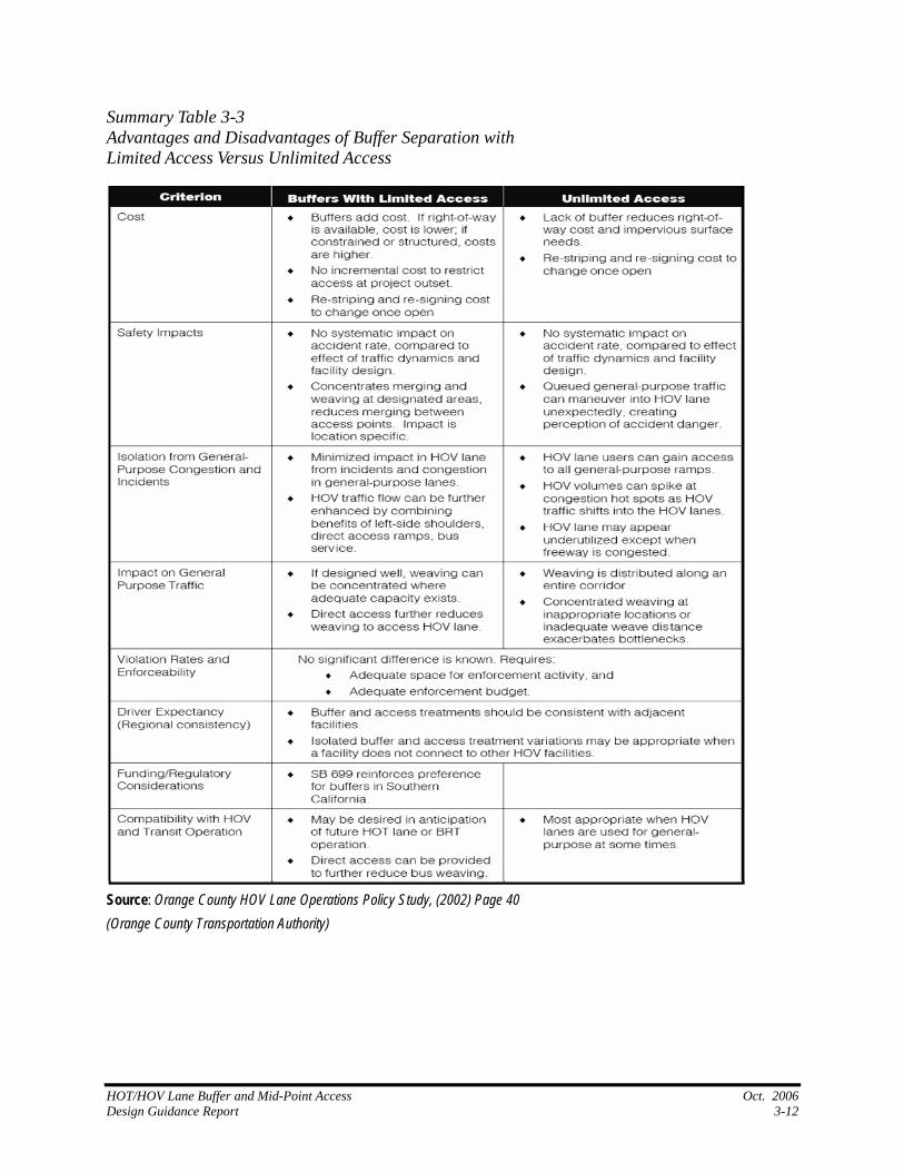
Summary Table 3-3 Advantages and Disadvantages of Buffer Separation with Limited Access Versus Unlimited Access
Source: Orange County HOV Lane Operations Policy Study, (2002) Page 40 (Orange County Transportation Authority)
HOT/HOV Lane Buffer and Mid-Point Access Oct. 2006 Design Guidance Report 3-12
3.3
3.3.1
ACCESS POINTS
As discussed in the previous section, ingress/egress to access points can vary depending upon buffer design and roadway configuration. The following presents a discussion of access point options as well as guidance for concurrent flow, buffer separated HOT lanes.
Combined Access
Access point designs currently in use across the country vary considerably. Exhibit 3-2 demonstrates the various access point designs for HOT lanes as found in the FHWA Guide for HOT Lane Development. A common design provides for ingress and egress to or from the HOV/ HOT lane by changing the buffer striping only. The prohibitive striping changes to permitted lane change striping, typically a single broken line, to allow vehicles to enter and leave the HOV/ HOT lane.
An alternative design includes a weave lane that is buffer-separated from the managed lanes. Where a separate weaving lane is provided, weaving traffic has to make two lane changes to arrive in the desired lane. The weaving lane was developed to better maintain speed and flows in the HOV/HOT lane. The project team was unable to find any hard data that supported this assumption. The weave lane is part of the Caltrans HOV Design Guidelines and is included in California managed lane access designs where possible. Additional research should be conducted to determine whether the weaving lanes provide for better operations in the HOV/HOT lane and, if so, under what conditions.
HOT/HOV Lane Buffer and Mid-Point Access Oct. 2006 Design Guidance Report 3-13
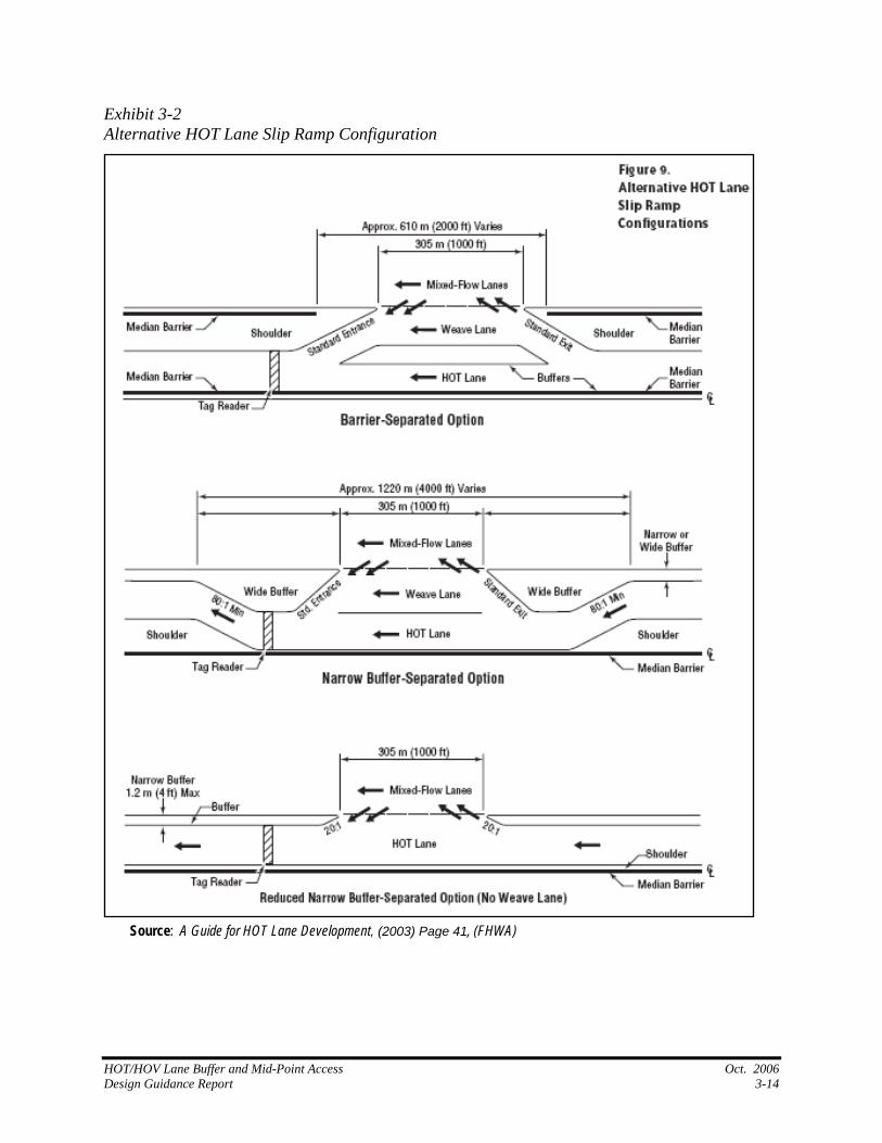
Exhibit 3-2 Alternative HOT Lane Slip Ramp Configuration
Source: A Guide for HOT Lane Development, (2003) Page 41, (FHWA)
HOT/HOV Lane Buffer and Mid-Point Access Oct. 2006 Design Guidance Report 3-14
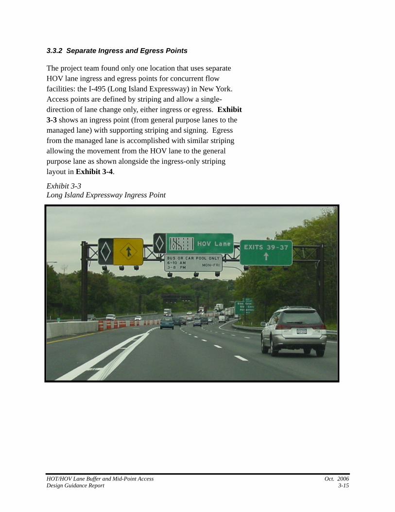
3.3.2 Separate Ingress and Egress Points
The project team found only one location that uses separate HOV lane ingress and egress points for concurrent flow facilities: the I-495 (Long Island Expressway) in New York. Access points are defined by striping and allow a single-direction of lane change only, either ingress or egress. Exhibit 3-3 shows an ingress point (from general purpose lanes to the managed lane) with supporting striping and signing. Egress from the managed lane is accomplished with similar striping allowing the movement from the HOV lane to the general purpose lane as shown alongside the ingress-only striping layout in Exhibit 3-4.
Exhibit 3-3 Long Island Expressway Ingress Point
HOT/HOV Lane Buffer and Mid-Point Access Oct. 2006 Design Guidance Report 3-15
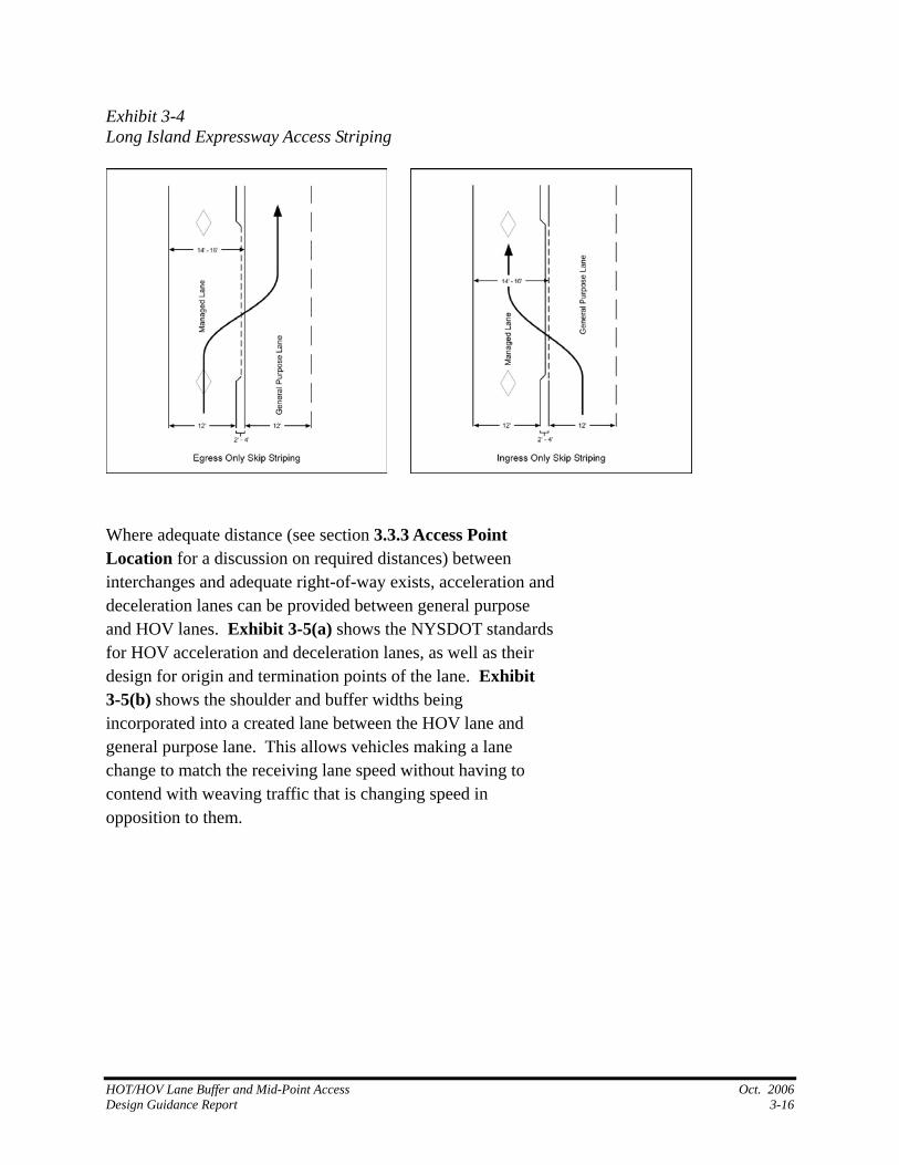
Exhibit 3-4
Long Island Expressway Access Striping
here adequate distance (see section 3.3.3 Access Point
and
ds
ane and
WLocation for a discussion on required distances) between interchanges and adequate right-of-way exists, accelerationdeceleration lanes can be provided between general purpose and HOV lanes. Exhibit 3-5(a) shows the NYSDOT standarfor HOV acceleration and deceleration lanes, as well as their design for origin and termination points of the lane. Exhibit 3-5(b) shows the shoulder and buffer widths being incorporated into a created lane between the HOV lgeneral purpose lane. This allows vehicles making a lane change to match the receiving lane speed without having tocontend with weaving traffic that is changing speed in opposition to them.
HOT/HOV Lane Buffer and Mid-Point Access Oct. 2006 Design Guidance Report 3-16
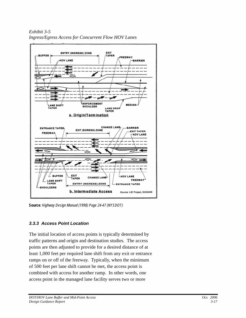
Exhibit 3-5 Ingress/Egress Access for Concurrent Flow HOV Lanes
Source: Highway Design Manual (1998) Page 24-47 (NYSDOT)
3.3.3 Access Point Location
The initial location of access points is typically determined by traffic patterns and origin and destination studies. The access points are then adjusted to provide for a desired distance of at least 1,000 feet per required lane shift from any exit or entrance ramps on or off of the freeway. Typically, when the minimum of 500 feet per lane shift cannot be met, the access point is combined with access for another ramp. In other words, one access point in the managed lane facility serves two or more
HOT/HOV Lane Buffer and Mid-Point Access Oct. 2006 Design Guidance Report 3-17
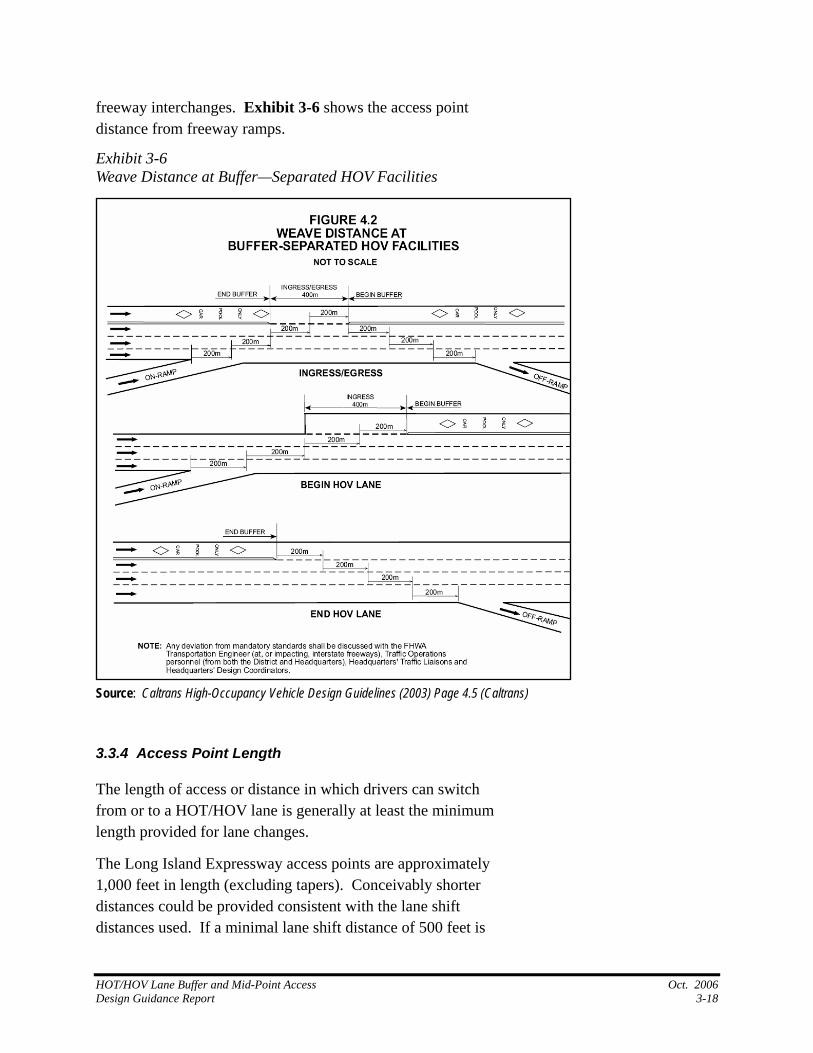
freeway interchanges. Exhibit 3-6 shows the access point distance from freeway ramps.
Exhibit 3-6 Weave Distance at Buffer—Separated HOV Facilities
Source: Caltrans High-Occupancy Vehicle Design Guidelines (2003) Page 4.5 (Caltrans)
3.3.4 Access Point Length
The length of access or distance in which drivers can switch from or to a HOT/HOV lane is generally at least the minimum length provided for lane changes.
The Long Island Expressway access points are approximately 1,000 feet in length (excluding tapers). Conceivably shorter distances could be provided consistent with the lane shift distances used. If a minimal lane shift distance of 500 feet is
HOT/HOV Lane Buffer and Mid-Point Access Oct. 2006 Design Guidance Report 3-18
used to locate the access point and if access to or from the HOT/HOV lane is restricted to one movement, then the access opening could be as short as 500 feet. (Note: As stated earlier, the Long Island Expressway is the only location encountered that is providing separated access. Therefore no access points of less than 1,000 feet have been observed. A decision to provide a shorter access length, even on a separated access, should be reviewed carefully). A combined access using the same minimal lane change distance should provide at least 1,000 feet (2 x 500 feet per lane change) of access.
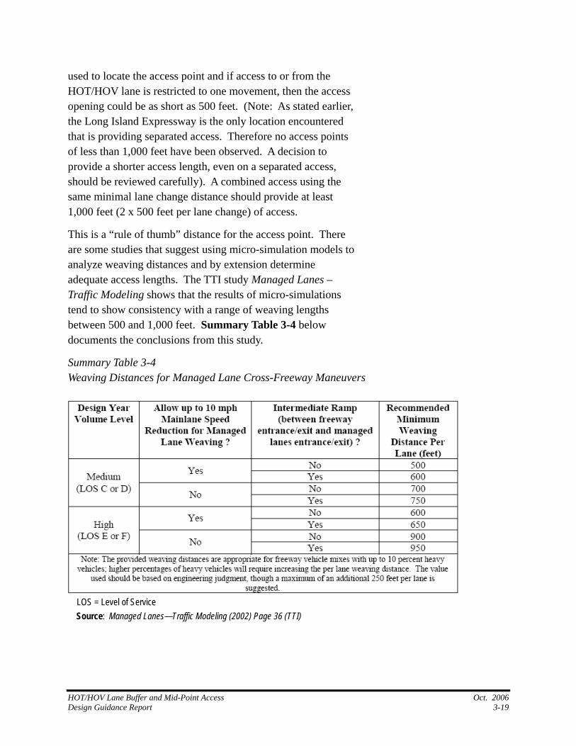
This is a “rule of thumb” distance for the access point. There are some studies that suggest using micro-simulation models to analyze weaving distances and by extension determine adequate access lengths. The TTI study Managed Lanes – Traffic Modeling shows that the results of micro-simulations tend to show consistency with a range of weaving lengths between 500 and 1,000 feet. Summary Table 3-4 below documents the conclusions from this study.
Summary Table 3-4
LOS = Level of Service
Weaving Distances for Managed Lane Cross-Freeway Maneuvers
Source: Managed Lanes—Traffic Modeling (2002) Page 36 (TTI)
HOT/HOV Lane Buffer and Mid-Point Access Oct. 2006 Design Guidance Report 3-19
3.3.5
3.4
Recommended Access Point Design
Ideally, access points will be located based on origin/ destination studies and will provide separate locations for ingress and egress. The distance from an interchange to the access point will provide upwards of 1,000 feet per lane change required. The length of the access point should be a minimum of 1,000 feet. This is important especially where separate ingress and egress points can be located, an acceleration/deceleration lane will be provided between the managed lanes and the general purpose lanes.
Where the ideal access point locations can not be accommodated, the following compromises can be used to provide adequate access to and from the managed lanes:
Minimum of 500 feet provided for each lane change required to access the managed lane from an on-ramp or vice versa.
Combine Ingress and Egress points. In other words allow both ingress and egress at the same location.
Remove the acceleration/deceleration lane.
ENFORCEMENT
This enforcement discussion relies heavily on the information provided in NCHRP Report 414 HOV Systems Manual. The enforcement strategies used for HOV lanes typically transfer readily to enforcing HOT lane operations. In most cases there is the added burden for the enforcing officer to have to first determine if the HOT lane occupancy requirements are met, and if not, then ascertain whether a toll has been paid. Various electronic and visual strategies are used to allow officers to make the second determination. In the case of I-25 in Denver where two lanes will be provided, CDOT has assigned vehicles to either be in an HOV lane or a toll lane. Under this enforcement strategy, a toll paying vehicle will still be ticketed if it is traveling in the HOV lanes. Enforcement of tolls will be done electronically, so an HOV traveling in the toll lane will be ticketed if a toll has not been paid.
HOT/HOV Lane Buffer and Mid-Point Access Oct. 2006 Design Guidance Report 3-20
Effective enforcement policies and programs are essential for the successful operation of a HOT lane facility. Several strategies can be used to provide enforcement with the type of enforcement chosen largely depending upon the type of design. Buffer-separated facilities require a different enforcement strategy than a barrier separated facility.
Typical enforcement on HOT lanes often requires dedicated enforcement areas, which are usually located immediately adjacent to the HOT lane facility and downstream of a tolling location. This configuration allows enforcement personnel to monitor the facility as well as pursue and apprehend violators to issue appropriate citations. Where separate HOT/HOV lanes are provided (I-25 in Denver, Colorado) the tolling can be enforced with photo enforcement technology.
Enforcement areas can be classified as low-speed or high-speed and usually by type of separation from the general purpose lanes. The following descriptions and guidelines are provided by NCHRP Report 414—HOV Systems Manual (pp. 6.69-6.76)
3.4.1 Low Speed Enforcement Areas
Low-speed enforcement areas are associated with barrier-separated freeway facilities. These enforcement areas are usually located at entrance or exit points where vehicle speeds are relatively slow, typically below 45 mph.
The following design features may be considered with slow-speed enforcement areas:
An at least 100 foot long enforcement area and preferably up to 200 foot area on high-volume facilities, not including approach and departure tapers.
An enforcement area 14 to 15 feet wide.
An enforcement area with a departure taper of 10:1 or 150 feet to allow for vehicle acceleration into the lane.
HOT/HOV Lane Buffer and Mid-Point Access Oct. 2006 Design Guidance Report 3-21
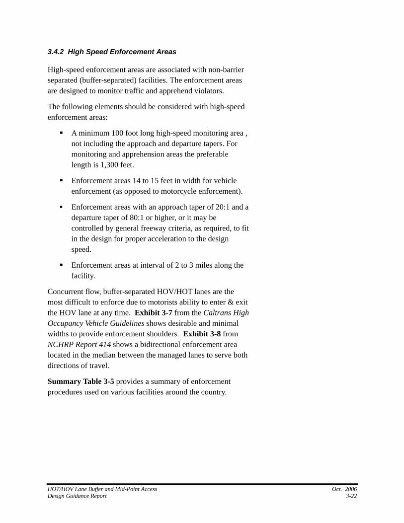
3.4.2 High Speed Enforcement Areas
High-speed enforcement areas are associated with non-barrier separated (buffer-separated) facilities. The enforcement areas are designed to monitor traffic and apprehend violators.
The following elements should be considered with high-speed enforcement areas:
A minimum 100 foot long high-speed monitoring area , not including the approach and departure tapers. For monitoring and apprehension areas the preferable length is 1,300 feet.
Enforcement areas 14 to 15 feet in width for vehicle enforcement (as opposed to motorcycle enforcement).
Enforcement areas with an approach taper of 20:1 and a departure taper of 80:1 or higher, or it may be controlled by general freeway criteria, as required, to fit in the design for proper acceleration to the design speed.
Enforcement areas at interval of 2 to 3 miles along the facility.
Concurrent flow, buffer-separated HOV/HOT lanes are the most difficult to enforce due to motorists ability to enter & exit the HOV lane at any time. Exhibit 3-7 from the Caltrans High Occupancy Vehicle Guidelines shows desirable and minimal widths to provide enforcement shoulders. Exhibit 3-8 from NCHRP Report 414 shows a bidirectional enforcement area located in the median between the managed lanes to serve both directions of travel.
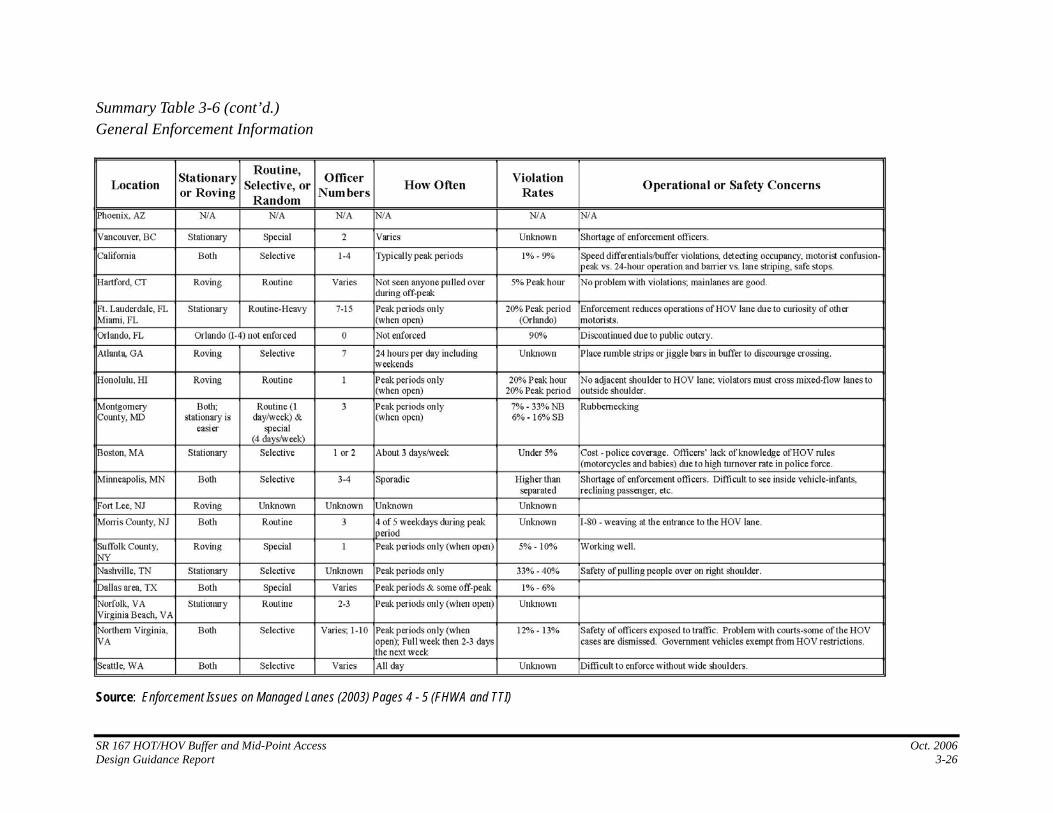
Summary Table 3-5 provides a summary of enforcement procedures used on various facilities around the country.
HOT/HOV Lane Buffer and Mid-Point Access Oct. 2006 Design Guidance Report 3-22
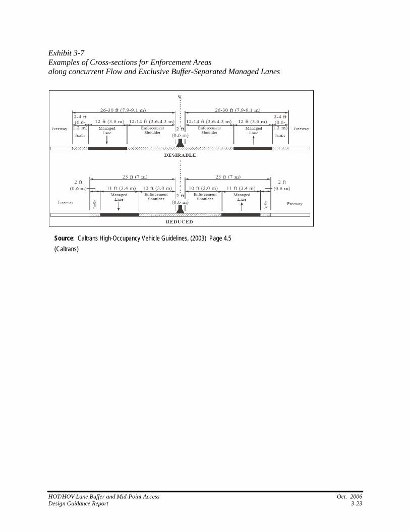
Exhibit 3-7 Examples of Cross-sections for Enforcement Areas along concurrent Flow and Exclusive Buffer-Separated Managed Lanes
Source: Caltrans High-Occupancy Vehicle Guidelines, (2003) Page 4.5 (Caltrans)
HOT/HOV Lane Buffer and Mid-Point Access Oct. 2006 Design Guidance Report 3-23
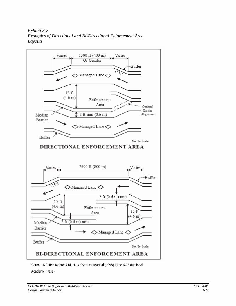
HOT/HOV Lane Buffer and
Source: NCHRP Report 414, HOV Systems Manual (1998) Page 6-75 (National Academy Press)
Exhibit 3-8 Examples of Directional and Bi-Directional Enforcement Area Layouts
Mid-Point Access Oct. 2006 Design Guidance Report 3-24
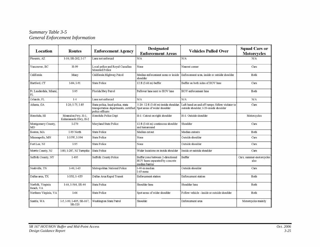
Summary Table 3-5 General Enforcement Information
SR 167 HOT/HOV Buffer and Mid-Point Access Oct. 2006 Design Guidance Report 3-25
SR 167 HOT/HOV Buffer and Mid-Point Access Oct. 2006 Design Guidance Report 3-26
Source: Enforcement Issues on Managed Lanes (2003) Pages 4 - 5 (FHWA and TTI)
Summary Table 3-6 (cont’d.) General Enforcement Information
4. RECOMMENDATIONS
This chapter summarizes the recommendations for HOT lane buffer and access points. It is based on the literature and information gathered from existing and planned facilities.
4.1
4.2
4.3
BUFFER AND INSIDE SHOULDER WIDTH
Where feasible, a buffer-separated facility should have a separation width of 4 feet between the HOT/HOV lane and the adjacent general purpose lane.
A continuous inside shoulder of 14 feet is desirable for enforcement and to serve as a breakdown lane. The minimum section should provide at least a 2-foot buffer (except at access points) and a 2-foot inside shoulder to separate the travel lane from any barrier if installed. An enforcement/breakdown area should be a minimum of 10 feet wide.
ACCESS POINT LOCATION
Access points should be located so that there is a distance of between 500 and 1,000 feet or more per lane change required to move from a ramp to the managed lane or vice versa; the higher number being the desired distance and the lower number being the minimum.
ACCESS POINT LENGTH
Access to or from the HOT/HOV lane should be consistent with the above guidance, providing at least the minimum acceptable distance per lane change to set the access point length for each movement. For a combined access (allowing both ingress and egress), the length of the access point should be at least twice the minimum acceptable lane change distance.
SR 167 HOT/HOV Buffer and Mid-Point Access Oct. 2006 Design Guidance Report 4-27
As described in Section 3.4.1.4 the decision to provide an access length of less than 1,000 feet should be carefully studied for safety and effectiveness.
4.4
4.5
ACCESS POINT DESIGN
The ideal access point design will provide separate locations for ingress and egress. Between the managed lane and the general purpose lane, an auxiliary lane will be provided to allow vehicles to accelerate or decelerate as appropriate. Immediately downstream of the access point an enforcement shoulder should be provided to allow enforcement officers to monitor access to the managed lanes.
Often insufficient right of way or distance between interchanges exists to provide the ideal solution. In such cases, access points can be combined to allow ingress and egress at the same point and if necessary or desired, the auxiliary lane can be removed.
At a minimum the striping will change from the prohibited buffer “double white stripe” to permissive skip white striping.
FINAL CONSIDERATIONS
While the recommendations included in this study represent the state of the practice, it is important to note that they are the “best available” based on recent experience. Extensive research designed to definitively identify the impacts of the different designs does not exist, particularly regarding access design where physical constraints often determine the type of access (combined, vs. separate, whether a weave lane is provided, etc.). In existing facilities, every effort is made to adequately balance the desire for high levels of service in the managed lanes with providing safe and efficient access and separation options.
The design recommendations provided is based on previous system experience, engineering judgment, and where existing, results of applicable research. The appropriate design for any new or converted managed lane will vary based on field specific conditions including existing right-of-way, available pavement width, design traffic volumes, facility type, traffic
SR 167 HOT/HOV Buffer and Mid-Point Access Oct. 2006 Design Guidance Report 4-28
mix, etc. As such, Chapter 3.0 discusses the options in detail. These explanations are intended to assist the engineer using these guidelines in making adjustments, as appropriate, for the specific project being designed.
SR 167 HOT/HOV Buffer and Mid-Point Access Oct. 2006 Design Guidance Report 4-29
APPENDIX A: REFERENCES
1. Parsons Brinckerhoff, Texas Transportation Institute. Report FHWA-OP-03-009, A
Guide for HOT Lane Development. U.S. Department of Transportation, Federal Highway Administration, 2003.
2. Parsons Brinckerhoff Quade and Douglas, Inc. Orange County High Occupancy Vehicle (HOV) Operations Policy Study, Study prepared for Orange County Transportation Authority, August 2002.
3. California Department of Transportation (Caltrans), Department of Transportation, Division of Traffic Operations High Occupancy Vehicle (HOV) Guidelines for Planning, Design and Operations, California Department of Transportation, 2003.
4. Texas Transportation Institute, Parsons, Brinckerhoff, Quade, and Douglas, and Pacific Rim Resources. NCHRP Report 414: HOV Systems Manual. TRB, National Research Council, Washington, D.C., 1998.
5. Cothron, A.S., Ranft, S.E., Walters, C.H., Fenno, D.W., and Lord, D., Research Report FHWA/TX-04/0-4434-1, Crash Analysis of Selected High-Occupancy Vehicle Facilities in Texas: Methodology, Findings, and Recommendations, , Texas Transportation Institute, The Texas A&M University System, College Station, Texas, May 2004.
6. Stockton, W.R., Daniels, G.F., Skowronek, D.A., and Fenno, D.W. Research Project 0-1353, The ABC’s of HOV The Texas Experience. Texas Transportation Institute, The Texas A&M University System, College Station, Texas, September 1999.
7. Skowronek, D.A., Ranft, S.E. and Cothron, A.S. Research Report TX-02/4961-4, An Evaluation of Dallas Area HOV Lanes, Year 2001. Texas Transportation Institute, The Texas A&M University System, College Station, Texas, November 2002.
8. Stockton, W., Benz, R., Rilett, L., Skowronek, D.A., Vadali, S., and Daniels G. Research Report TX-00-4915-1, Investigating the General Feasibility of High Occupancy/Toll
SR 167 HOT/HOV Buffer and Mid-Point Access APPENDIX A Design Guidance Report
Lanes in Texas. Texas Transportation Institute, The Texas A&M University System, College Station, Texas, December, 2000.
9. Sullivan, E. Continuation Study to Evaluate the Impacts of the SR 91 Value Priced Express Lanes. Department of Civil & Environmental Engineering, Cal Poly State University, San Luis Obispo, California, December, 2000.
10. Collier, T. and Goodin, G.D. Research Report FHWA/TX-02/4160-7, Marketing the Managed Lanes Concept., Texas Transportation Institute, The Texas A&M University System, College Station, Texas, April, 2002.
11. Stockton, W. and Daniels, G. Project Summary Report 7-4915-S, Considerations in Assessing the Feasibility of High-Occupancy Toll Lanes. Texas Transportation Institute, The Texas A&M University System, College Station, Texas, 2000.
12. Safirova, E., Gillingham, K., Harrington, W., and Nelson, P. Are HOT Lanes a Hot Deal? The Potential Consequences of Converting HOV to HOT Lanes in Northern Virginia. Urban Complexities Issue Brief, Washington, DC: Resources for the Future, 2003.
13. Cothron, S. A., Skoronek, D. A., Kuhn, B. T. Enforcement Issues on Managed Lanes. Texas Transportation Institute, The Texas A&M University System, College Station, Texas, January 2003.
14. Kuhn, B. T, Goodin, G. D., Brewer, M., Collier, T., Fitzpatrick, K., Jasek, D., Venglar, S., Interim Manual for Managed Lanes. Texas Transportation Institute, The Texas A&M University System, College Station, Texas, October, 2003.
15. New York State Department of Transportation, Design Division - Design Quality Assurance Bureau. Highway Design Manual – Chapter 24. New York State Department of Transportation, May, 1998.
16. Golob, T. F., Wrecker, W. W., Alvarez, V. M., Safety Aspects of Freeway Weaving Sections. Paper dated November, 2002, Presented at the 82nd Annual Meeting of the Transportation Research Board. January 12-26, 2003, Washington, DC
17. Venglar, S., Fenno, D., Goel, S., Schrader, P., Managed Lanes – Traffic Modeling. Texas Transportation Institute, The Texas A&M University System, College Station, Texas, December, 2001.
18. Fitzpatrick, K., Brewer, M. A., Venglar, S. Managed Lane Ramp and Roadway Design Issues. Texas Transportation Institute, The Texas A&M University System, College Station, Texas, January, 2003.
SR 167 HOT/HOV Buffer and Mid-Point Access APPENDIX A Design Guidance Report
APPENDIX B: Summary of Reports
SR 167 HOT/HOV Buffer and Mid-Point Access APPENDIX B Design Guidance Report
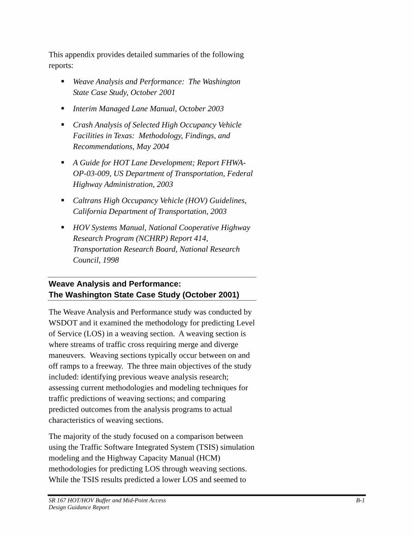
This appendix provides detailed summaries of the following reports:
Weave Analysis and Performance: The Washington State Case Study, October 2001
Interim Managed Lane Manual, October 2003
Crash Analysis of Selected High Occupancy Vehicle Facilities in Texas: Methodology, Findings, and Recommendations, May 2004
A Guide for HOT Lane Development; Report FHWA-OP-03-009, US Department of Transportation, Federal Highway Administration, 2003
Caltrans High Occupancy Vehicle (HOV) Guidelines, California Department of Transportation, 2003
HOV Systems Manual, National Cooperative Highway Research Program (NCHRP) Report 414, Transportation Research Board, National Research Council, 1998
Weave Analysis and Performance: The Washington State Case Study (October 2001)
The Weave Analysis and Performance study was conducted by WSDOT and it examined the methodology for predicting Level of Service (LOS) in a weaving section. A weaving section is where streams of traffic cross requiring merge and diverge maneuvers. Weaving sections typically occur between on and off ramps to a freeway. The three main objectives of the study included: identifying previous weave analysis research; assessing current methodologies and modeling techniques for traffic predictions of weaving sections; and comparing predicted outcomes from the analysis programs to actual characteristics of weaving sections.
The majority of the study focused on a comparison between using the Traffic Software Integrated System (TSIS) simulation modeling and the Highway Capacity Manual (HCM) methodologies for predicting LOS through weaving sections. While the TSIS results predicted a lower LOS and seemed to
SR 167 HOT/HOV Buffer and Mid-Point Access B-1 Design Guidance Report
produce results consistent with field results, the sample size was too small to be considered statistically significant. The authors indicated that the HCM methodologies were the accepted state of the practice and, based on their research, could not recommend changing that practice in Washington.
Recommendations made by the authors included incorporating significant engineering judgment into design decisions, not treating weaving congestion as a localized phenomena, and utilizing traffic modeling programs such as TSIS as part of the engineering analysis. The authors did warn, however, that on-site observations of weaving sections should be conducted when considering traffic modeling analysis, especially when complicated geometry exists. Additionally, further examination of the safety impacts of weaving sections needs to be conducted.
Interim Managed Lane Manual (October 2003)
The Interim Managed Lane Manual was drafted by Texas Transportation Institute (TTI) in cooperation with the Federal Highway Administration (FHWA) and the Texas Department of Transportation (TxDOT) and was submitted as a draft in October 2003. At this time, the final version is not readily available.
Chapter 4—“Managed Lanes Facility Design” has a wealth of information regarding managed lanes, separations, and access point locations. The chapter addresses many design elements of managed lanes including design speed and clearances, as well as access and buffer design. The manual includes recommended design standards, but does not provide specific analysis. However, the manual does provide some discussion about general analysis considerations.
The report noted that since a majority of the HOV facilities are retrofitted to existing highway rights of way, some design compromises may need to be considered. In that regard, desirable design elements may not always be realistic. Desirable criteria include all the preferred design elements and generally reflect criteria associated with permanent or new facility construction, meeting American Association of State
SR 167 HOT/HOV Buffer and Mid-Point Access B-2 Design Guidance Report
Highway and Transportation Officials (AASHTO) and other standards.
Designs with reduced elements reflect the inability to meet the desirable criteria due to lack of available right-of-way or other limiting factors. Reduced designs do not reflect those associated with permanent facilities and each reduced design should be considered on a case-by-case basis based on sound engineering practices.
The design and operational components of a managed lane facility must be considered simultaneously. Right-of-way constraints will usually govern the extent of design that is possible. When reduced design standards are implemented, the operations component of the managed lane development becomes increasingly important.
Recommendations from the report include the following:
Design speed of 70 mph (desirable) and 50 mph (minimum) for rural and 70 mph (desirable and minimum) for urban managed lane facilities.
Design speed of 70 mph (desirable) and 50 mph (reduced) for barrier-separated, 60 mph (desirable) and 50 mph (reduced) for concurrent flow, and 50 mph (desirable) and 30 mph (reduced) for contraflow managed lane facilities.
Horizontal clearance to fixed objects of 5 feet is desired, however, 2 feet should be provided as a minimum at barriers, sign columns, and other obstructions.
Lane width for the managed lane of 12 feet is desired with a minimum width of 11 feet.
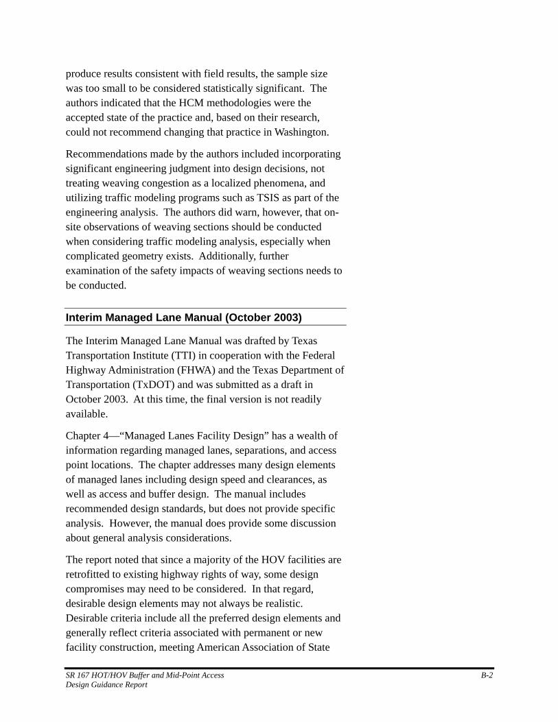
The Interim Managed Lane Manual provides diagrams for buffer-separated facilities as shown in Appendix B Figure 1.
SR 167 HOT/HOV Buffer and Mid-Point Access B-3 Design Guidance Report
Appendix B Figure 1 Buffer-Separated Facilities
Source: Interim Managed Lane Manual (2003) Page 4-27 (TTI, FHWA, TxDOT)
SR 167 HOT/HOV Buffer and Mid-Point Access B-4 Design Guidance Report
Crash Analysis of Selected High Occupancy Vehicle Facilities in Texas: Methodology, Findings, and Recommendations (May 2004)
A research study conducted by TTI in 2004 analyzed crashes on selected HOV facilities in Texas. The objective of the research was to develop a better understanding of the safety issues associated with HOV lanes; particularly buffer-separated, concurrent flow HOV lanes. The research team analyzed injury crash data from three freeway corridors in the Dallas area. The HOV lane safety survey results indicate that for the buffer-separated HOV facilities, safety issues can be attributed to ingress and egress difficulty, illegal crossing of the buffer, high speed differentials, and reduced inside shoulder widths.
The study also noted that crashes on roadways after the introduction of HOV lanes tend to be higher than what would be expected as a result of growth alone. The authors present data that suggest higher crash rates are most significantly impacted by the speed differential between the HOV lanes and the general purpose lanes. Appendix B Figure 2 illustrates TTI’s recommended cross-section design for buffer-separated facilities.
SR 167 HOT/HOV Buffer and Mid-Point Access B-5 Design Guidance Report
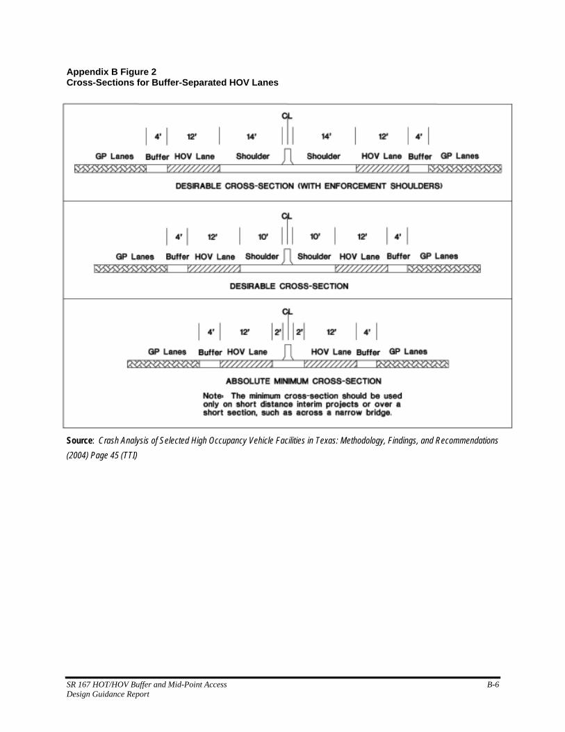
Appendix B Figure 2 Cross-Sections for Buffer-Separated HOV Lanes
Source: Crash Analysis of Selected High Occupancy Vehicle Facilities in Texas: Methodology, Findings, and Recommendations (2004) Page 45 (TTI)
SR 167 HOT/HOV Buffer and Mid-Point Access B-6 Design Guidance Report
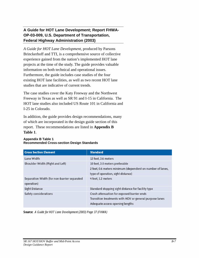
A Guide for HOT Lane Development; Report FHWA-OP-03-009, U.S. Department of Transportation, Federal Highway Administration (2003)
A Guide for HOT Lane Development, produced by Parsons Brinckerhoff and TTI, is a comprehensive source of collective experience gained from the nation’s implemented HOT lane projects at the time of the study. The guide provides valuable information on both technical and operational issues. Furthermore, the guide includes case studies of the four existing HOT lane facilities, as well as two recent HOT lane studies that are indicative of current trends.
The case studies cover the Katy Freeway and the Northwest Freeway in Texas as well as SR 91 and I-15 in California. The HOT lane studies also included US Route 101 in California and I-25 in Colorado.
In addition, the guide provides design recommendations, many of which are incorporated in the design guide section of this report. These recommendations are listed in Appendix B Table 1.
Appendix B Table 1 Recommended Cross-section Design Standards
Source: A Guide for HOT Lane Development (2003) Page 37 (FHWA)
SR 167 HOT/HOV Buffer and Mid-Point Access B-7 Design Guidance Report
Caltrans High Occupancy Vehicle (HOV) Guidelines, California Department of Transportation (2003)
The High Occupancy Vehicle (HOV) Guidelines were prepared by Caltrans to provide a “how to” for the planning, design, and operations of HOV facilities. The guidelines clearly state that they are advisory in nature and are to be used only when every effort to conform to established standards has been exhausted. Additionally, the guidelines instruct that when conformance is not possible, the deviation must be documented by a sound and defensible analysis and an approved design exception fact sheet. The guidance covers important topics such as planning, operations, geometric design, ingress and egress, signs and markings, and enforcement.
Analysis considerations for separation design follow a hierarchy of preferences. The first choice is to design two-way barrier-separated facilities. When right-of-way and/or environmental constraints exist, a reversible, barrier-separated design should be utilized. If barrier-separated designs do not fit a specific application, buffer-separated designs should be considered. As a last resort, if no buffer can be provided, contiguous designs can be employed, however these are usually associated with short duration, high-volume peak commute traffic periods.
Appendix B Figure 3 illustrates Caltrans’ typical cross-sections for buffer-separated facilities.
SR 167 HOT/HOV Buffer and Mid-Point Access B-8 Design Guidance Report
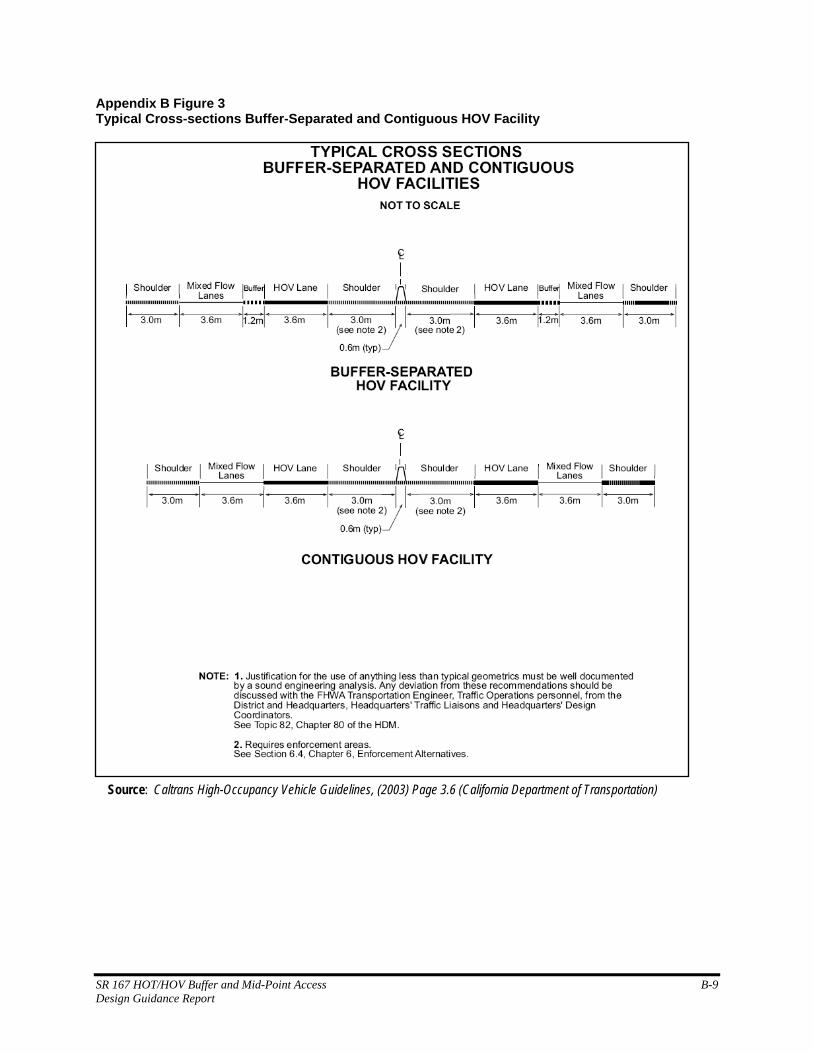
Appendix B Figure 3 Typical Cross-sections Buffer-Separated and Contiguous HOV Facility
Source: Caltrans High-Occupancy Vehicle Guidelines, (2003) Page 3.6 (California Department of Transportation)
SR 167 HOT/HOV Buffer and Mid-Point Access B-9 Design Guidance Report
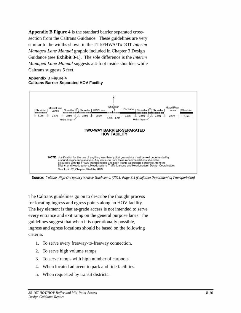
Appendix B Figure 4 is the standard barrier separated cross-section from the Caltrans Guidance. These guidelines are very similar to the widths shown in the TTI/FHWA/TxDOT Interim Managed Lane Manual graphic included in Chapter 3 Design Guidance (see Exhibit 3-1). The sole difference is the Interim Managed Lane Manual suggests a 4-foot inside shoulder while Caltrans suggests 5 feet.
Appendix B Figure 4 Caltrans Barrier-Separated HOV Facility
Source: Caltrans High-Occupancy Vehicle Guidelines, (2003) Page 3.5 (California Department of Transportation)
The Caltrans guidelines go on to describe the thought process for locating ingress and egress points along an HOV facility. The key element is that at-grade access is not intended to serve every entrance and exit ramp on the general purpose lanes. The guidelines suggest that when it is operationally possible, ingress and egress locations should be based on the following criteria:
1. To serve every freeway-to-freeway connection.
2. To serve high volume ramps.
3. To serve ramps with high number of carpools.
4. When located adjacent to park and ride facilities.
5. When requested by transit districts.
SR 167 HOT/HOV Buffer and Mid-Point Access B-10 Design Guidance Report
6. To assist in the modification of local commute patterns (may be at local request).
7. To help balance and optimize interchange operational level of service within a local jurisdiction, within a corridor, or within a region.
8. To support and encourage ride sharing programs (HOV demand/usage).
When considering buffer-separated facilities, ingress and egress locations should be relative to the origin and destination patterns of HOVs. If the majority of HOVs originate upstream and have destinations downstream of the facility, they will all use the HOV facility, and there will be little impact related to intermediate access points. However, intermediate access points will allow greater use of the facility.
A critical component in determining access point locations is the operation of weaving sections. It is important that ingress and egress points be of proper length and location to provide the best possible access, especially to adjoining freeways. There could be situations in which merging to and from the HOV lane can create queuing in the HOV lane. One example would be providing ingress and egress near ramp locations on a freeway that has many closely spaced ramps in a bottleneck section. This could create conflicts in the flow of both the HOV and mainline facilities. Design should include the consideration of an additional lane between these ramps to allow ingress/egress to the HOV facility without adversely impacting either it or the mixed-flow lanes.
Provisions for traffic to enter and leave the HOV facility should be provided at every freeway-to-freeway interchange. Ingress and egress to state highways and major arterials should be considered where demand exists and where operation is not severely impacted. Ingress and egress locations should be on a tangent and away from enforcement areas whenever possible.
Appendix B Figure 5 and Appendix B Figure 6 summarize Caltrans’ recommendations for access point design and location for both barrier-separated and buffer-separated facilities.
SR 167 HOT/HOV Buffer and Mid-Point Access B-11 Design Guidance Report
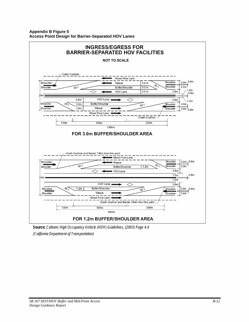
Appendix B Figure 5 Access Point Design for Barrier-Separated HOV Lanes
Source: Caltrans High Occupancy Vehicle (HOV) Guidelines, (2003) Page 4.4 (California Department of Transportation)
SR 167 HOT/HOV Buffer and Mid-Point Access B-12 Design Guidance Report
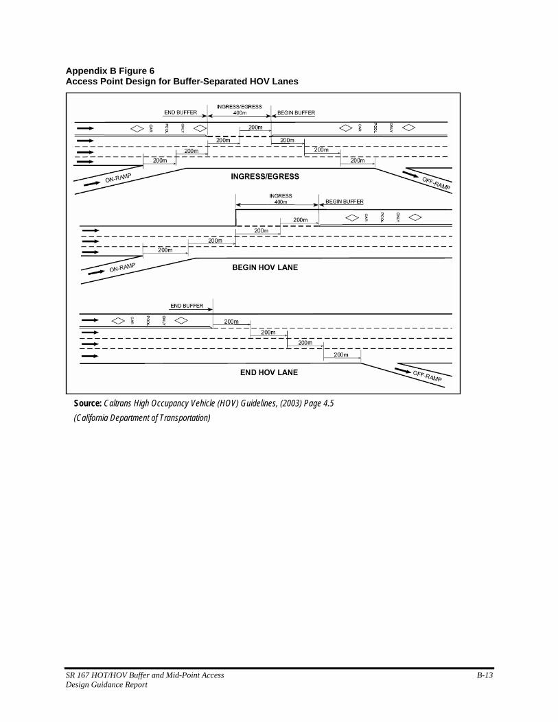
Appendix B Figure 6 Access Point Design for Buffer-Separated HOV Lanes
Source: Caltrans High Occupancy Vehicle (HOV) Guidelines, (2003) Page 4.5 (California Department of Transportation)
SR 167 HOT/HOV Buffer and Mid-Point Access B-13 Design Guidance Report
HOV Systems Manual, National Cooperative Highway Research Program (NCHRP) Report 414, Transportation Research Board, National Research Council, National Academy Press, Washington, D.C. (1998)
The HOV Systems Manual provides a comprehensive guide to developing policies, planning, designing, implementing, marketing, operating, enforcing, and evaluating HOV facilities. The manual evaluates existing procedures and specifications for various aspects of HOV systems to identify alternatives and discuss their applicability. One of the objectives of the manual is to promote consistency and effectiveness in HOV applications throughout the country. NCHRP Report 414 designs are referenced in some of the Caltrans cross-sections as well as directly in Chapter 3 of this report.
Chapter six of the HOV Systems Manual pertains most directly to this study regarding buffer and access design. The chapter summary found on page 1-3 of the report states that “Chapter 6 presents the design elements associated with HOV facilities on freeways and in separate rights-of-way. It includes information on the design process, the groups that are usually included in this process, vehicle design criteria, and the design features of barrier separated, concurrent flow, and contraflow HOV lanes, as well as different types of access treatments. Examples of cross-sections, signing and pavement markings, and other design elements are presented.”
As we found in our research, the NCHRP Report 414 states on page 6-34 that, “Concurrent flow HOV facilities are often developed by retrofitting an existing freeway cross-section. For example, the inside shoulder or center median may be converted to an additional lane, or the freeway right-of-way may be expanded and a HOV lane added. As a result, a wide range of design treatments are found with these types of projects.” Those same reasons account for the variability found in conversions to HOT lanes.
SR 167 HOT/HOV Buffer and Mid-Point Access B-14 Design Guidance Report
APPENDIX C: Summary of Agency Interviews
SR 167 HOT/HOV Buffer and Mid-Point Access APPENDIX C Design Guidance Report
This appendix provides a summary of findings from interviews with six transportation agencies in the United States. Each of these agencies is either operating or implementing HOT lanes in their respective state. The six agencies are:
Minnesota Department of Transportation (MinnDOT)
Colorado Department of Transportation (CDOT)
Orange County Transportation Authority (OCTA)
California Department of Transportation (Caltrans)
Texas Department of Transportation (TxDOT)
New York State Department of Transportation (NYSDOT)
I-394 HOT Lanes—Minneapolis, Minnesota
Interstate 394 (I-394) is an 11-mile section of freeway with three miles of barrier-separated, reversible HOT lanes and eight miles of buffer-separated HOT lanes. The buffer-separated portion has a standard configuration of a 3-foot inside shoulder, a 12-foot HOT lane, a 2-foot buffer, multiple 12-foot general purpose lanes, and a 10-foot outside shoulder. Enforcement areas are provided in select locations downstream of transponder readers. The Minnesota Department of Transportation (MinnDOT) works with the Minnesota State Patrol to provide daily enforcement of the HOT lanes. In their determination, enforcement is a key component to maintaining adequate levels of service in the HOT lanes.
When preparing for the conversion to HOT lanes, Nick Thompson, Operations Manager of the I-394 project stated that representatives from MinnDOT conducted tours of existing facilities and reviewed existing standards. They then had to adapt the designs they saw during their research to I-394’s unique conditions. Specifically, the impact of snow removal operations restricted their choice of lane markings and the consideration of supplemental separators such as tubular delineators.
SR 167 HOT/HOV Buffer and Mid-Point Access C-1 Design Guidance Report
Design Decisions: In locating their access points, MinnDOT attempted to use a generous 1,500 feet per required lane shift to access the HOT lanes. There are several high volume interchanges located in an 8-mile section of I-394 as it intersects four freeways within that distance. These interchanges were MinnDOT’s priority in determining the location of access points. Furthermore, accesses to and from other I-394 ramps were fixed based on physical and geometric constraints. Ultimately, MinnDOT adjusted the 1,500-foot per lane shift as required to provide adequate service based on origin and destination data. In some cases, MinnDOT needed to consolidate access points to and from the HOT lanes. The cross-section and buffer width used reduced some element widths to less than desirable to make sure all widths were at least the minimum recommended. These decisions varied depending on the width of existing pavement, locations of bridge piers, etc.
Successes and Failures: Officials indicated that although the HOT lanes generally have been considered successful, there may be some areas for improvement. Ideas discussed include allowing access anywhere along the system and reconfiguring the enforcement light at tolling locations to face upstream. Nick Thompson said that providing unlimited access to HOT facilities is worth considering further. While recognizing that tolling an unlimited access facility would pose a significant design challenge, the experience in Minnesota has been that congestion in the managed lanes tends to build from the access points.
Another idea discussed was that the toll readers used on I-394 have an “enforcement light” that allows officers to visually recognize whether a toll has been paid or not. Mr. Thompson suggests that allowing drivers upstream of the tolling location to see this light would provide some self enforcement. When drivers know that the enforcement light will signal to other upstream drivers that they have not paid a toll, they are less
SR 167 HOT/HOV Buffer and Mid-Point Access C-2 Design Guidance Report
likely to commit this access violation. In other words, providing other drivers this indication removes peer anonymity.
I-25 Downtown Express—Denver, Colorado
The existing I-25 Bus/HOV lanes, also known as Downtown Express lanes, are being converted to HOT lanes between downtown Denver and 70th Avenue, a distance of 6.6 miles, and will consist of a 2-lane, barrier-separated, reversible facility in the median of I-25. The lanes will be used by southbound traffic from 5:00 am to 10:00 am and by northbound traffic from noon to 3:00 am. The freeway section consists of the express lanes plus four general purpose lanes in each direction. The current section inside the barriers consists of a 10-foot shoulder, two 12-foot HOV lanes, and a 4-foot shoulder. Since the lanes are reversible, the breakdown lane will be on the inside in one direction and on the outside in the other. The existing HOV lanes that are being converted to HOT lanes are only accessible at the ends of the facility. There was no compelling reason to allow new access points. By limiting access to each end, the Colorado Department of Transportation (CDOT) is able to operate the facility with only two toll readers.
Myron Swisher of the CDOT indicated that this HOT lane facility will feature time-based variable pricing of Single Occupant Vehicles (SOVs). SOVs will be excluded from access to the facility if the LOS in the HOT lane drops below a set threshold. The system, as a HOT lane facility, is yet to be placed into service; hence there were no safety or enforcement issues identified.
Design Decisions: CDOT reviewed existing toll lane operations elsewhere and found the I-15 facility in San Diego to be most similar to the proposed I-25 facility. CDOT focused their effort on researching tolls and tolling operations. The primary focus of CDOT’s HOT lane project is to maintain transit reliability. The tolling will be time based and the tolls will be displayed on non-changing signs. The tolls will be set conservatively high to maintain transit (bus) travel times. Construction is
SR 167 HOT/HOV Buffer and Mid-Point Access C-3 Design Guidance Report
underway to provide a cross-section of a 10-foot shoulder, two 12-foot travel lanes, and another 15-foot shoulder between barriers. Enforcement will take place from the 15-foot shoulder, on the drivers left or right depending on which direction the vehicles are traveling. In effort to provide the best opportunity for occupancy enforcement, one of the lanes will be restricted for HOVs while the other lane will be the HOT lane. The HOV lane will always be next to the 15-foot enforcement shoulder regardless of which direction the lanes are traveling. Colorado State Patrol will enforce occupancy requirements while cameras will enforce the toll lane. Once a vehicle is in a lane, it will not be permitted to change lanes though the lanes are separated only by striping.
The lane restrictions and configuration were determined mainly because of retrofit constraints and a desire to simplify enforcement of the differing requirements (multiple passengers versus toll paying vehicles). The enforcement design was coordinated with the State Police and State legislature to allow video enforcement of the tolls.
Successes and Failures: The tolled lanes are scheduled to open in spring of 2006. Since the lanes are not yet in operation, there are no successes or failures of the reconfigured lanes to report.
State Route 91 Express Lanes - Orange County, California
State Route 91 (SR 91) is a 10-mile toll facility providing two lanes in each direction between the SR 91/55 junction in Anaheim and the Orange/Riverside County Line. The facility runs in the median and access points are provided at each end of the express facility. The availability of additional publicly-owned right-of-way played an important role in the creation of the facility. SR 91 was the first fully automated toll road in the United States. Due to the lack of traditional funding sources for adding more capacity to SR 91, the California Department of Transportation (Caltrans) looked to private sources for funding. Thus, SR 91 was planned, constructed, and is operated by a
SR 167 HOT/HOV Buffer and Mid-Point Access C-4 Design Guidance Report
private company, the California Private Transportation Company (CPTC).
Mr. Dipak Roy, P.E., Senior Project Manager of the Orange County Transportation Authority (OCTA) provided information about the design and operation of the SR 91 toll facility. The two lanes in each direction are restricted in a manner similar to the operation of the proposed I-25 lanes in Denver. One lane is for HOVs with 3 or more passengers and the second lane is tolled. Enforcement is accomplished thorough a combination of California Highway Patrol and photo enforcement. Bi-directional enforcement areas in the median allow officers to observe vehicles entering and leaving the HOT/HOV lanes.
The HOT/HOV lanes are separated from the general purpose lanes by double-double yellow lines. The distance of the buffer from edge of lane line to edge of lane line is 4 feet. Between the lane lines is a flexible barrier of tubular pylons. The pylons are placed 6 feet on center.
Design Decisions: When the SR 91 HOV lanes were designed over 15 years ago, the main constraint on design was the available right-of-way. The cross-section used as described from the median barrier is a 4-foot inside shoulder, two 12-foot HOV lanes, and a 4-foot buffer between the HOV lanes and general purpose lanes.
Successes and Failures: Mr. Roy indicated that even with the pylons they have a number of drivers violate the access requirements of the express lanes either by trying to avoid the toll and enforcement areas or by using the lanes for shorter trips, creating their own access points through the pylons. OCTA replaces approximately 1,000 pylons per month. He stated that while the cost of maintaining the pylons was high, the barrier was essential to successful operation of the facility. His sense is that without the pylons enforcement would be impossible.
SR 167 HOT/HOV Buffer and Mid-Point Access C-5 Design Guidance Report
Interstate-15 Express Lanes—San Diego, California
The existing I-15 Express Lanes facility is an 8-mile, 2-lane, reversible HOT lane facility. The facility currently extends northerly on I-15 from the junction with SR 163 to the junction with SR 56. The current HOT lane facility is a conversion from an HOV facility. The facility uses a dynamic, real-time tolling structure, which allows the toll to vary with the level of congestion.
Lynn Barton, Project Manager of the Traffic Operations Division of the California Department of Transportation (Caltrans) provided insight into the operation of these lanes and on the current expansion project. In regard to the existing HOV lane barrier separated facility, Mr. Barton indicated that the lanes were originally built in 1988 as an HOV-only facility. In the early 1990s, there was public pressure to open the lanes to mixed-flow traffic due to excess capacity in the HOV lanes. At this time, the San Diego Association of Governments (SANDAG) proposed a demonstration project that would allow SOVs to use the HOV lanes for a fee. Soon after legislative authorization to begin road pricing on the lanes was secured, a pilot project began in December 1996. Full electronic toll collection (ETC) was achieved in March 1998. Today, all tolling is done via ETC at high-speed on the open Express Lanes. When the HOV lanes added the SOVs, the lanes became HOT lanes.
Caltrans is responsible for the physical construction and maintenance of the lanes. The SANDAG operates the tolling system on the HOT lanes and contracts with the California Highway Patrol (CHP) for enforcement of the lanes. From its inception, the road pricing project was not set up to make money. The idea was to move people. Dynamic Tolling is used to control demand for the excess capacity in the HOT lanes. The proceeds from the tolling operation covers the cost of operating the toll system, system maintenance and enforcement. Any excess revenue is used to fund an Express Bus route that operates in the I-15 corridor.
SR 167 HOT/HOV Buffer and Mid-Point Access C-6 Design Guidance Report
Since the system is barrier-separated and has no intermediate access points, there is a single tolling point located approximately two miles from the south end of the facility. Toll rates are dynamically adjusted as often as every six minutes in order to maintain acceptable levels of service in the HOT lanes. A time delay is programmed into the ETC system’s calculation to ensure that the price displayed on the variable message sign (VMS) near the facility’s entrances is the same toll rate that is charged to the patrons’ accounts. Pricing depends on vehicle usage on the HOT lanes and not on the mixed flow lanes.
Currently, construction is underway to extend the existing HOT lanes an additional 8 miles to the north and call them the Managed Lanes. There will be four lanes in this barrier-separated section with a moveable barrier. The moveable barrier allows for adjusting the number of lanes to accommodate unbalanced directional splits. The barrier can allow for two lanes each inbound and outbound, three lanes in one direction and one lane in the opposing direction, or in an extreme case, four lanes in one direction.
Design Decisions: The section currently under construction will allow for intermediate access points. These will be accomplished with slip ramps from the managed lanes to a weave lane next to the innermost general purpose lanes. The access points were located and designed according to the Caltrans HOV Design Guidelines as were the cross-section and enforcement shoulder widths. These guidelines are based on California’s experience with HOV lanes as well as current research. The Guidelines, referenced earlier in this report, were last published in 2003.
In addition to allowing for traditional buses, HOVs, and tolled vehicles, a Bus Rapid Transit system (BRT) also will be accommodated by the new lanes. The BRT busses will access the managed lanes by way of dedicated ramps.
This new facility is scheduled to open in 2007. The tolling system has yet to be finalized. The remaining two projects in this corridor will widen the existing two lane Expressway to four lanes and extend the Managed Lanes four more miles to
SR 167 HOT/HOV Buffer and Mid-Point Access C-7 Design Guidance Report
the north. This will provide a total length of 20 miles of Managed Lanes that should be completed in about 2012.
After this corridor is completed, other corridors will be considered in the San Diego area.
Successes and Failures: Initially, the tolling was done via prepaid monthly decals that were mounted to the windshield of a select number of SOVs. Following the installation of the ETC system, tolling became dynamic and was applied per trip. The public perception is generally positive and Caltrans and SANDAG receive very few complaints about the system.
Houston Managed Lane Network—Houston, Texas
The Houston Metropolitan Transit Authority’s (METRO) High Occupancy Vehicle (HOV) lanes were originally built primarily for buses. However, the HOV system also promotes ridesharing through vanpools and carpools, which reduce traffic congestion and provide environmental benefits throughout the region. Drivers need only observe the occupancy requirements, rules of the road, and hours of operation in order to use the system. Vehicles not allowed on the HOV lanes include SOVs, vehicles towing trailers of any sort, and trucks with more than two axles or a load capacity of one ton or greater.
METRO operates and maintains HOV lanes on six of Houston's major freeway corridors to serve the eight-county region. Generally, the HOV lanes move morning rush-hour traffic inbound toward downtown, Monday-Friday from 5:00 a.m. to 11:00 a.m. During afternoon and evening rush hours, from 2:00 p.m. to 8:00 p.m., the HOV lanes reverse, moving traffic outbound away from downtown. METRO currently operates a total of 112.9 miles of HOV lanes of a planned 115-mile HOV lane network:
IH 45 North (North Freeway) US 59 North (Eastex Freeway) IH 45 South (Gulf Freeway) US 59 South (Southwest Freeway)* IH 10 West (Katy Freeway)
SR 167 HOT/HOV Buffer and Mid-Point Access C-8 Design Guidance Report
US 290 West (Northwest Freeway)
* A 2.1-mile addition to the Southwest HOV lane is under construction. [Text provided by METRO website: http://www.ridemetro.org/services/hovsystem.asp]
Physically located in the center of most major Houston freeways, the HOV lanes are typically single-lane, reversible, barrier-separated roadways that allow buses, vanpools, carpools and motorcycles to move higher volumes of passengers to and from downtown. The only exceptions to this configuration are the Katy Diamond Lanes. The Katy Diamond Lanes operate the same as the other HOV lanes with the caveat that they employ a single-direction, buffer-separated design. In place of the barrier are two distinctive white stripes consisting of an 8-inch stripe, a 32-inch buffer, and another 8-inch stripe, resulting in a 4-foot wide buffer, which help guide commuters to their destination quickly and easily while warning mainstream traffic against entering the restricted lanes. The Katy Diamond Lanes provide limited points of legal entry in order to preserve a premium Level of Service.
As previously mentioned, the HOV network was designed and built as a high-speed lane for mass transit buses and vanpools. Eventually, carpools were included as allowable users in order to increase the efficiency of the lanes. From a safety perspective, these lanes (including the travel lane and shoulders) are generally at least 19.5 feet wide, which is sufficient clearance for a bus to pass when another has pulled over to the right.
Some performance measures Houston uses to gauge their managed lane operations include:
The HOV lanes facilitate almost 118,000 person trips each weekday, serving about 36,400 vehicle trips that would otherwise continue traveling the mainline lanes.
The average rush-hour speed on Houston freeways is roughly 24 miles per hour. HOV lanes maintain an operating speed of roughly 50-55 miles per hour, hence saving the average HOV commuter 12 to 22 minutes per trip.
SR 167 HOT/HOV Buffer and Mid-Point Access C-9 Design Guidance Report
The HOV network is as efficient as 24 freeway lanes, which, if combined, would equal the amount of rush-hour passengers traveling the HOV lane network.
[Text provided by METRO website: http://www.ridemetro.org/services/hovsystem.asp]
Currently Texas has two operational HOT lanes, which are collectively known as QuickRide and include the Northwest Freeway and the Katy Freeway. The HOT lanes operate as normal HOV lanes for a majority of the day. However, during peak rush hours, these HOV lanes raise the minimum requirements for free ridership to 3+ passengers while allowing commuters with two passengers to continue using the HOV lanes for $2 each way. The Northwest Freeway operates under the program inbound between 6:45 a.m. and 8:00 a.m. The Katy Freeway operates under the program inbound between 6:45 a.m. and 8:00 a.m. and outbound between 5:00 p.m. and 6:00 p.m. [Text provided by METRO website: www.ridemetro.org]
A 23-mile stretch of the Katy Freeway is currently undergoing reconstruction and the Katy HOV lane is in a constant state of change. The ultimate configuration of the Katy Freeway will consist of a 10-foot outside shoulder, four 12-foot mainline lanes, and a 10-foot inside shoulder. Additionally, there will be HOT lanes between IH 610 and SH 6 consisting of a 10-foot outside shoulder, two 12-foot HOT lanes, and a 4-foot inside shoulder in each direction. The HOT lanes will be, barrier-separated from the general purpose lanes. The entrance and access points for the proposed HOT lanes are shown in
(dropped text)
SR 167 HOT/HOV Buffer and Mid-Point Access C-10 Design Guidance Report
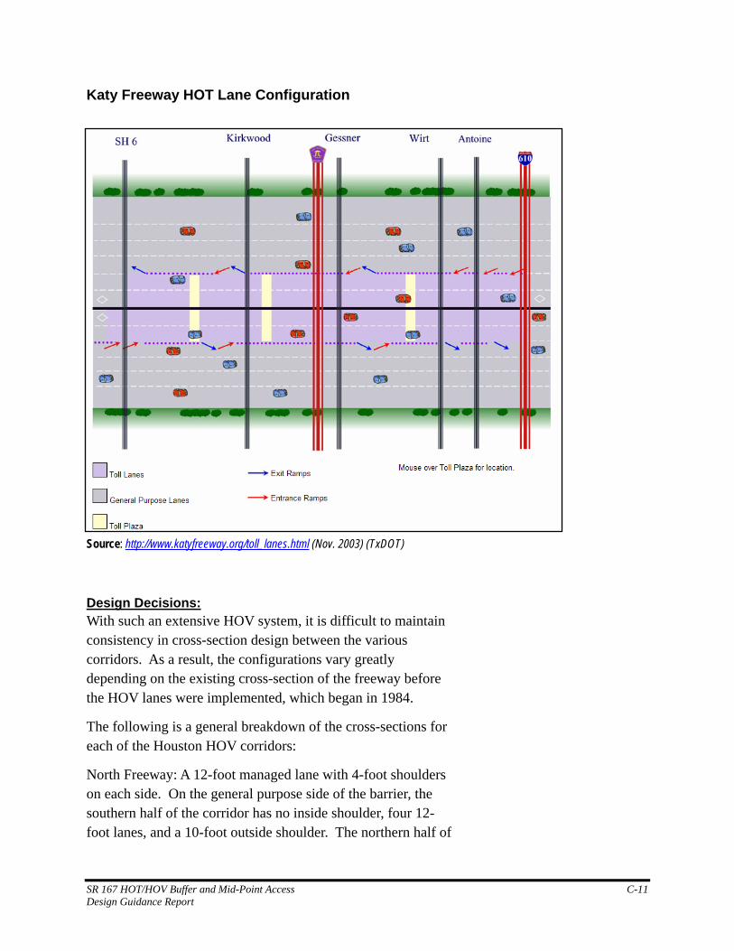
Katy Freeway HOT Lane Configuration
Source: http://www.katyfreeway.org/toll_lanes.html (Nov. 2003) (TxDOT)
Design Decisions: With such an extensive HOV system, it is difficult to maintain consistency in cross-section design between the various corridors. As a result, the configurations vary greatly depending on the existing cross-section of the freeway before the HOV lanes were implemented, which began in 1984.
The following is a general breakdown of the cross-sections for each of the Houston HOV corridors:
North Freeway: A 12-foot managed lane with 4-foot shoulders on each side. On the general purpose side of the barrier, the southern half of the corridor has no inside shoulder, four 12-foot lanes, and a 10-foot outside shoulder. The northern half of
SR 167 HOT/HOV Buffer and Mid-Point Access C-11 Design Guidance Report
this corridor has the same configuration with the exception of a 10-foot inside shoulder.
Eastex Freeway: A 12-foot managed lane with 6-foot shoulders on each side for southern two-thirds of the corridor and a 12-foot managed lane with 10-foot shoulders on each side for the northern third of the corridor. On the general purpose side of the barrier, the section remains constant with a 10-foot inside shoulder, five 12-foot lanes, and a 10-foot outside shoulder.
Gulf Freeway: A 12-foot managed lane with 4-foot shoulders on each side. On the general purpose side of the barrier, the northern third consists of no inside shoulder, four 12-foot lanes, and a 10-foot outside shoulder; the middle third consists of a 10-foot inside shoulder, four 12-foot lanes, and a 10-foot outside shoulder; and the southern third consists of a 10-foot inside shoulder, three 12-foot lanes, and a 10-foot outside shoulder.
Southwest Freeway: A 12-foot managed lane with 4-foot shoulders on each side. On the general purpose side of the barrier, the section remains constant with a 10-foot inside shoulder, four 12-foot lanes, and a 10-foot outside shoulder.
Northwest Freeway: A 12-foot managed lane with 4-foot shoulders on each side. On the general purpose side of the barrier, the north third consists of a 10-foot inside shoulder, four 12-foot lanes, and a 10-foot outside shoulder, while the southern two-thirds consists of no inside shoulder, four 12-foot lanes, and a 10-foot outside shoulder.
Many reasons contributed to the reduction in shoulder widths on the Houston HOV system. The most notable is the fact the HOV lanes were retrofits of existing freeways. In some cases, the existing pavement could not be widened to the outside due to the densely populated and extremely expensive property in the area. Where this was the case, the HOV lanes were constructed by “borrowing” the inside shoulders in each direction. This resulted in the minimum HOV section of a 12-foot lane with a 4-foot shoulder on each side and no inside shoulder on the general purpose lanes. Where some widening could occur, the HOV section was increased to provide 6-foot
SR 167 HOT/HOV Buffer and Mid-Point Access C-12 Design Guidance Report
shoulders on each side. Preferably though, the HOV section consisted of a 12-foot lane with a 10-foot shoulder on each side and a 10-foot inside shoulder on the general purpose lanes.
The use of barriers for a majority of the system can be attributed to the original intent of providing a dedicated express lane for buses in order to better manage schedules and provide transit users trip reliability.
Strategically placed ramps along the lanes allow drivers to enter or exit the HOV lane mainly from remote Park & Ride lots and Transit Centers, but also, to a lesser extent, from the general purpose lanes. One-way ramps operate as an entrance in the morning and exit in the evening. Two-way ramps are both entrance and exit, mornings and evenings. Cross ramps and Wishbone ramps are both designed to allow access to/from both sides of the freeway, while Tee ramps are used when access is only needed from one side of the freeway. Slip ramps allow freeway traffic to merge into or out of the general purpose lanes. Generally slip ramps are not used to allow mid-point access; however, most Houston HOV lanes start/end with this type of configuration. [Information provided by METRO website: www.ridemetro.org]
Successes and Failures: With regard to the buffer separated “Diamond Lanes” on the Katy Freeway, Nader Mirjamali, Senior Transportation Engineer with Metropolitan Transit Authority of Harris County, stated that the primary operational problems they have with the diamond lanes is enforcement. There are restricted access points; but, drivers will access the diamond lanes from any location.
In addition, the inside shoulder is not wide enough to provide enforcement. When enforcing traffic violations in the managed lanes the violating vehicle and the officer must cross all lanes of traffic to the outside shoulder.
Even with the high violation rates, the managed lanes maintain operating speeds of between 50 and 55 mile per hour.
SR 167 HOT/HOV Buffer and Mid-Point Access C-13 Design Guidance Report
Dallas Managed Lane Network—Dallas, Texas
The Dallas area managed lane network consists of four HOV corridors, two of which are buffer-separated while the other two are barrier-separated. The Texas Transportation Institute (TTI) researched the feasibility of HOV alternatives, for a number of corridors, for the Dallas Area Rapid Transit District (DART) and the Texas Department of Transportation (TxDOT). The analysis resulted in the recommendation to begin HOV operations on two buffer-separated corridors including IH 35E (Stemmons Freeway) and IH 635 (LBJ Freeway) as well as two barrier-separated corridors including IH 35E (South RL Thornton/Marvin D Love Freeway) and IH 30 (East RL Thornton Freeway). The Dallas HOV network was created with the intent of relieving congestion on the parallel general purpose lanes by encouraging carpools and transit use, but it was not specifically geared towards buses as was the Houston system.
Design Decisions: Buffer-Separated HOV Lanes: The Stemmons Freeway HOV lanes opened in 1996 and consist of a single, concurrent-flow buffer-separated lane in each direction. The HOV lane is 11½ feet wide with a 2 foot – 10 inch buffer consisting of a 4-inch white stripe, a 26-inch space with two reflective raised pavement markers, and another 4-inch white stripe. The inside shoulder varies in width, ranging from a usual 2 feet to approximately 14 feet to accommodate enforcement vehicles at specific locations. In this corridor, there are three entrances and three exits in both the northbound and southbound directions. These concurrent-flow HOV lanes operate 24 hours a day.
The LBJ Interchange Bypass is a short, reversible HOV lane section on the Stemmons Freeway that provides an alternative to the significant congestion that occurs in the vicinity of the IH 35E/IH 635 Interchange. It operates southbound during morning peak periods from 6:00 a.m. to 9:00 a.m. and northbound during afternoon peak periods from 3:30 p.m. to 7:00 p.m. on weekdays only.
SR 167 HOT/HOV Buffer and Mid-Point Access C-14 Design Guidance Report
The LBJ Freeway HOV lanes opened in 1997 and consist of a single, concurrent-flow buffer-separated lane in each direction. The HOV lane is 11 feet wide with a 3-foot buffer consisting of a 4-inch white stripe, a 32-inch space with two reflective raised pavement markers, and another 4-inch white stripe. The inside shoulder varies in width, ranging from a usual 3 feet to approximately 14 feet to accommodate enforcement vehicles at specific locations. In this corridor, there are three entrances and three exits in the westbound direction, and four entrances and exits in the eastbound direction. These concurrent-flow HOV lanes operate 24 hours a day.
[Information provided by DART website www.DART.org]
Barrier-Separated HOV Lanes: The South RL Thornton/Marvin D Love Freeway HOV lanes, that opened in 2002, consist of both a concurrent-flow, buffer-separated lane as well as a single-lane, reversible, barrier-separated lane. The concurrent-flow portion comprises a 12-foot lane with a 2-foot buffer consisting of a 4-inch white stripe, a 20-inch space with two reflective raised pavement markers, and another 4-inch white stripe. The inside shoulder varies in width, ranging from a usual 2 feet to approximately 16 feet to accommodate enforcement vehicles at specific locations. For the concurrent-flow lanes in this corridor, there is one entrance and one exit in each direction, and the lanes operate 24 hours a day. The reversible portion consists of a 12-foot lane with two 4-foot shoulders on each side. For the reversible lane, there are two entrances and two exits in each direction. The northbound hours of operation are from 6:00 a.m. to 10:00 a.m. while the southbound hours are from 2:30 p.m. to 7:00 p.m. [Information provided by DART website www.DART.org]
The East RL Thornton Freeway HOV lanes opened in 1991 as the first contraflow lanes in the State of Texas. Based on TTI research, it was decided that the IH 30 roadway geometry and traffic patterns best suited the use of the moveable barrier technology, with major congestion in the peak direction and spare capacity in the opposite direction. The moveable concrete barrier also provides the safety of physical separation of opposing traffic flows making the HOV lane accessible to car pools. Twice a day, five days a week, 10 miles of barrier is
SR 167 HOT/HOV Buffer and Mid-Point Access C-15 Design Guidance Report
transferred, from 11 to 22 feet, to create an additional lane for commuters into and out of Dallas. The HOV lane is 12 feet wide with no offset to the barrier and a 10-foot inside shoulder. [Information provided by Barrier Systems, Inc. website www.barriersystemsinc.com]
The westbound contraflow lane has two entrances and one exit while the eastbound lane has one entrance and two exits. Since this corridor is a contraflow lane, only one direction is open at a time, operating during the morning peak period from 6:00 a.m. to 9:00 a.m. and in the afternoon peak period from 3:30 p.m. to 7:00 p.m. [Information provided by DART website www.DART.org]
I-495 (Long Island Expressway)—New York, New York
Interstate 495 in New York (The Long Island Expressway) was recently reconstructed to provide a buffer-separated HOV lane in both the inbound and outbound directions to the City of New York. The cross-section provides a standard 2-foot striped buffer that is either eliminated at access points or widened to provide acceleration or deceleration lanes depending on available right-of-way. The access points are typically 1,000 feet in length, providing separate points for the ingress and egress movements from the HOV lane.
This is the only facility that we found using separate ingress and egress points on a buffer-separated HOV lane. The design guidance section explains in detail the separate access point design. Where an auxiliary lane is created, the HOV lane shifts into the shoulder area using standard freeway lane shift taper lengths. The tapers are approximately 1,000 feet in length. The access point, including the acceleration/ deceleration lane, exists for approximately 1,000 feet. In other words, where auxiliary lanes are provided, the total length required for the access is approximately 3,000 feet.
Mark Bocamazo, Regional Design Engineer of the New York State Department of Transportation discussed the Long Island
SR 167 HOT/HOV Buffer and Mid-Point Access C-16 Design Guidance Report
Expressway. In total it is over 40-miles long. As the roadway approaches New York City, the right-of-way width shrinks dramatically. Where sufficient right-of-way existed access lanes were “shadowed out” whereby the HOV lane shifted into the inside shoulder to allow the creation of an acceleration or deceleration lane. Where there was insufficient right-of-way, the access points were defined by striping only. (The access points are described more fully in the design guidance section of this report.)
Design Decisions: The facility was planned and designed several years ago. The buffer widths follow existing standards (two to four feet in width depending on available right-of-way) with 14-foot shoulders. There are two-way enforcement areas that allow police to enforce either direction of traffic from a single point. Mr. Bocamazo indicated that the decisions for buffer width and separated access points were made many years ago and could not say what those reasons were. He did not see any reason to change those decisions, however.
Access locations were determined primarily by origin and destination data. Since the Long Island Expressway has multiple interchanges in relatively short distances, access to and from the HOV lane is combined for several interchanges.
Successes and Failures: The HOV lanes opened this past summer and therefore have only been in operation for a few months. One of the challenges at this point is re-educating drivers to understand the meaning of the various striping schemes. Access violation rates are currently high, but NYSDOT is working with the New York State Patrol on enforcement and educating drivers as to the meaning of the different striping.
SR 167 HOT/HOV Buffer and Mid-Point Access C-17 Design Guidance Report