Embed Size (px)
Citation preview
Manufacturing andMaterials Processing
Journal of
Communication
Hot Gas Forming of Aluminum Alloy Tubes UsingFlame Heating
Ali Talebi-Anaraki 1,* , Mehdi Chougan 2, Mohsen Loh-Mousavi 3 and Tomoyoshi Maeno 4
1 Department of Mechanical Engineering, Materials Science, and Ocean Engineering, Graduate School ofEngineering Science, Yokohama National University, Yokohama, Kanagawa 240-8501, Japan
2 College of Engineering, Design and Physical Sciences, Brunel University London, Uxbridge,Middlesex UB8 3PH, UK; [email protected]
3 Department of Mechanical Engineering, Khomeinishahr Branch, Islamic Azad University, Khomeinishahr,Isfahan 81857-93768, Iran; [email protected]
4 Division of Systems Research, Faculty of Engineering, Yokohama National University, Yokohama,Kanagawa 240-8501, Japan; [email protected]
* Correspondence: [email protected] or [email protected]
Received: 23 May 2020; Accepted: 13 June 2020; Published: 16 June 2020�����������������
Abstract: Hot metal gas forming (HMGF) is a desirable way for the automotive industry to producecomplex metallic parts with poor formability, such as aluminum alloys. A simple hot gas formingmethod was developed to form aluminum alloy tubes using flame heating. An aluminum alloytube was heated by a flame torch while the tube was rotated and compressed using a lathe machineand simultaneously pressurized with a constant air pressure. The effects of the internal pressureand axial feeding on expansion and wall thickness distribution were examined. The results showedthat the proposed gas forming method was effective for forming aluminum alloy tubes. It was alsoindicated that axial feeding is a vital parameter to prevent reductions in wall thickness by supplyingthe material flow during the forming process.
Keywords: gas forming; hot forming; tube forming; bulging; flame heating
1. Introduction
In recent years, light-weight materials such as aluminum alloys have been widely used inthe automotive and aerospace industries. Tube hydroforming is a well-known forming process thatis utilized to form tubular components with variable cross-sections using internal pressure media.However, it is difficult to gain a proper pressure path in hydroforming, and forming defects such asrupture or folding can occur.
The poor formability of low ductility materials such as aluminum alloys at room temperaturelimits their applications. Therefore, warm and hot forming processes have been proposed to increasethe formability of materials with low ductility at room temperature. Alzahrani et al. [1] analyticallymodeled a multi-nose symmetric tube in the hydroforming process based on a mechanistic approach.Afshar et al. [2] investigated the forming limit diagrams of hydroformed aluminum tubes to predictbursting, and they compared the numerical results with experimental tests. Keigler et al. [3] enhancedthe formability of aluminum components via warm hydroforming, and they studied the effect oftemperature controlling on wall thickness and microstructure before and after the forming process.Yi et al. [4] introduced a new combined heating system for the warm hydroforming of light-weightalloy tubes. Hwang et al. [5] examined the T-shape hydroforming of an AZ61 magnesium alloyat 150 and 300 ◦C. Chan and Kot [6] studied the formability of an AZ31B magnesium alloy madeby three different loading paths for quadrilateral tubular components fabricated by the warm tube
J. Manuf. Mater. Process. 2020, 4, 56; doi:10.3390/jmmp4020056 www.mdpi.com/journal/jmmp
J. Manuf. Mater. Process. 2020, 4, 56 2 of 9
hydroforming process. However, warm tube hydroforming has a limitation on the heating temperature:it is generally kept below 300 ◦C to prevent the evaporation of fluid media such as oil and water.
The limitation of the heating temperature in the tube forming can be eliminated by utilizing gasas a pressure medium. The hot metal gas forming (HMGF) of tubes is a novel hot-forming processthat is utilized to form hollow steel and aluminum alloy parts. In this process, a tube is formedinto a specific shape by gas or air pressure while the tube is heated before or during the formingprocess. Dykstra et al. [7] proposed the hot gas forming process to form hot metallic tubes. However,it is difficult to simultaneously control the heating temperature and internal pressure during gasforming due to the short deformation time of tubes in gas forming. Since internal gas pressure iscompressive and the volume of the pressure medium is automatically expanding, it is difficult to controlthe deformation behavior. Most often, electrical resistance or electromagnetic induction methods areused to heat tubes [8–12]. However, Joule heating requires a certain electrical resistance for heatingmaterials, and it is not suitable for heating an aluminum alloy with a high electric conductivity.Therefore, other heating methods such as flame heating can be effective for the heating of aluminumalloy tubes.
Vadillo et al. [13] compared their simulation and experimental results of the hot gas formingtechnology for high-strength steel and stainless-steel tubes. Maeno et al. [14] developed a hot gasbulging process for an aluminum alloy tube using resistance heating. Maeno et al. [15] optimizedthe forming condition in the hot tube gas bulging of aluminum alloys using resistance heating setinto dies. He et al. [16] investigated the mechanical properties and formability of TA2 extrudedtubes in HMGF at elevated temperatures. Maeno et al. [17] formed an ultra-high-strength steelhollow part by stamping an air-filled steel tube using resistance heating. Liu et al. [18] determinedthe formability of titanium tubular components for high-pressure gas forming at elevated temperatures.Paul and Strano [19] studied the influence of the process variables on the gas forming and presshardening of steel tubes. They also determined the effects of internal pressure and preheating onhardening and the surface finish. Talebi Anaraki et al. [20] developed the gas forming of tubes usingpulsating pressure and oscillating heating. Their results revealed that, upon applying pulsatingpressure, the wall thickness gradually decreased. The oscillated heating, accompanied by pulsatingpressure, increased the bulging area. Though large deformation zone is suitable for forming withdies, it is difficult to use forming dies with flame heating. The flame heating technique is suitablefor the dieless forming of tubes.
In hot tube forming using local heating, dieless forming has been studied. Hwang et al. [21]developed the dieless drawing of stainless steel for tube- or wire-drawing processes using ahigh-frequency heating source. Furushima and Manabe [22] reported the effectiveness of the dielessdrawing process for microtube fabrication. The dieless gas forming of tubes is an advancedmaterial-forming technology that can be classified as a flexible forming process with the absence of diematerials. Dieless gas forming can be utilized to manufacture automobile parts, pressure vessel heads,large elbow joints, etc.
In this paper, to utilize flame heating for dieless gas forming, local deformation behavior wasinvestigated. The gas forming of an aluminum alloy tube using fixed flame heating was performed.The effects of the internal pressure and axial feeding on the expansion and wall thickness distributionof the deformed tubes were evaluated in experiments. In addition, the effect of the gas forming processon the microstructure was studied.
2. Hot Gas Forming of Aluminum Alloy Tubes Using Flame Heating
Experimental Procedure
To investigate the bulging behavior in the local area, a hot gas forming apparatus was utilized tosimplify the equipment for the experimental approach and the heating of tubes using flame heating.It is difficult to control the generation of heat using resistance heating because it is dependent on
J. Manuf. Mater. Process. 2020, 4, 56 3 of 9
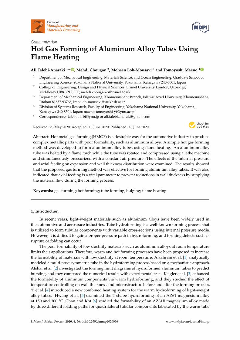
thickness. The heat generated in this case was concentrated on the heating portion due to the highcurrent density. However, by using flame heating, the heating portion can be controlled, which makes itsuitable for the heating of aluminum alloys with a low resistivity. The sequence of the hot gas formingof a tube using a lathe machine by flame heating and a schematic drawing of the tube and air sealingcomponents are shown in Figures 1 and 2, respectively. Conical bushes and brass housings were usedto seal the tube. The tube was filled with compressed air and provided with a flow control valve and anair compressor. The air that filled the tube was heated with a fixed flame torch placed a specific distanceaway during the experiments. To increase the uniformity of the temperature distribution of the tubeduring the forming process, the tube was rotated by employing a three-jaw chuck of the lathe machine.
J. Manuf. Mater. Process. 2020, 4, x FOR PEER REVIEW 3 of 9
makes it suitable for the heating of aluminum alloys with a low resistivity. The sequence of the hot gas forming of a tube using a lathe machine by flame heating and a schematic drawing of the tube and air sealing components are shown in Figures 1 and 2, respectively. Conical bushes and brass housings were used to seal the tube. The tube was filled with compressed air and provided with a flow control valve and an air compressor. The air that filled the tube was heated with a fixed flame torch placed a specific distance away during the experiments. To increase the uniformity of the temperature distribution of the tube during the forming process, the tube was rotated by employing a three-jaw chuck of the lathe machine.
Figure 1. Sequence of hot gas forming of the tube using flame heating: (a) setup and charge with compressed air; (b) start of flame heating and rotating of tube; and (c) start of axial feeding.
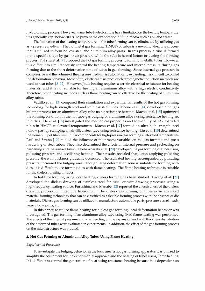
Figure 2. A schematic drawing of the tube and air sealing components.
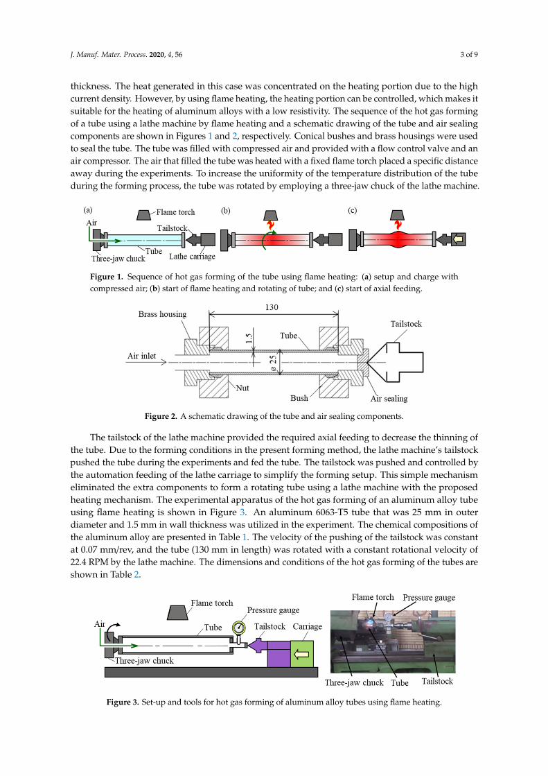
The tailstock of the lathe machine provided the required axial feeding to decrease the thinning of the tube. Due to the forming conditions in the present forming method, the lathe machine’s tailstock pushed the tube during the experiments and fed the tube. The tailstock was pushed and controlled by the automation feeding of the lathe carriage to simplify the forming setup. This simple mechanism eliminated the extra components to form a rotating tube using a lathe machine with the proposed heating mechanism. The experimental apparatus of the hot gas forming of an aluminum alloy tube using flame heating is shown in Figure 3. An aluminum 6063-T5 tube that was 25 mm in outer diameter and 1.5 mm in wall thickness was utilized in the experiment. The chemical compositions of the aluminum alloy are presented in Table 1. The velocity of the pushing of the tailstock was constant at 0.07 mm/rev, and the tube (130 mm in length) was rotated with a constant rotational velocity of 22.4 RPM by the lathe machine. The dimensions and conditions of the hot gas forming of the tubes are shown in Table 2.
Figure 3. Set-up and tools for hot gas forming of aluminum alloy tubes using flame heating.
Figure 1. Sequence of hot gas forming of the tube using flame heating: (a) setup and charge withcompressed air; (b) start of flame heating and rotating of tube; and (c) start of axial feeding.
J. Manuf. Mater. Process. 2020, 4, x FOR PEER REVIEW 3 of 9
makes it suitable for the heating of aluminum alloys with a low resistivity. The sequence of the hot gas forming of a tube using a lathe machine by flame heating and a schematic drawing of the tube and air sealing components are shown in Figures 1 and 2, respectively. Conical bushes and brass housings were used to seal the tube. The tube was filled with compressed air and provided with a flow control valve and an air compressor. The air that filled the tube was heated with a fixed flame torch placed a specific distance away during the experiments. To increase the uniformity of the temperature distribution of the tube during the forming process, the tube was rotated by employing a three-jaw chuck of the lathe machine.
Figure 1. Sequence of hot gas forming of the tube using flame heating: (a) setup and charge with compressed air; (b) start of flame heating and rotating of tube; and (c) start of axial feeding.
Figure 2. A schematic drawing of the tube and air sealing components.
The tailstock of the lathe machine provided the required axial feeding to decrease the thinning of the tube. Due to the forming conditions in the present forming method, the lathe machine’s tailstock pushed the tube during the experiments and fed the tube. The tailstock was pushed and controlled by the automation feeding of the lathe carriage to simplify the forming setup. This simple mechanism eliminated the extra components to form a rotating tube using a lathe machine with the proposed heating mechanism. The experimental apparatus of the hot gas forming of an aluminum alloy tube using flame heating is shown in Figure 3. An aluminum 6063-T5 tube that was 25 mm in outer diameter and 1.5 mm in wall thickness was utilized in the experiment. The chemical compositions of the aluminum alloy are presented in Table 1. The velocity of the pushing of the tailstock was constant at 0.07 mm/rev, and the tube (130 mm in length) was rotated with a constant rotational velocity of 22.4 RPM by the lathe machine. The dimensions and conditions of the hot gas forming of the tubes are shown in Table 2.
Figure 3. Set-up and tools for hot gas forming of aluminum alloy tubes using flame heating.
Figure 2. A schematic drawing of the tube and air sealing components.
The tailstock of the lathe machine provided the required axial feeding to decrease the thinning ofthe tube. Due to the forming conditions in the present forming method, the lathe machine’s tailstockpushed the tube during the experiments and fed the tube. The tailstock was pushed and controlled bythe automation feeding of the lathe carriage to simplify the forming setup. This simple mechanismeliminated the extra components to form a rotating tube using a lathe machine with the proposedheating mechanism. The experimental apparatus of the hot gas forming of an aluminum alloy tubeusing flame heating is shown in Figure 3. An aluminum 6063-T5 tube that was 25 mm in outerdiameter and 1.5 mm in wall thickness was utilized in the experiment. The chemical compositions ofthe aluminum alloy are presented in Table 1. The velocity of the pushing of the tailstock was constantat 0.07 mm/rev, and the tube (130 mm in length) was rotated with a constant rotational velocity of22.4 RPM by the lathe machine. The dimensions and conditions of the hot gas forming of the tubes areshown in Table 2.
J. Manuf. Mater. Process. 2020, 4, x FOR PEER REVIEW 3 of 9
makes it suitable for the heating of aluminum alloys with a low resistivity. The sequence of the hot gas forming of a tube using a lathe machine by flame heating and a schematic drawing of the tube and air sealing components are shown in Figures 1 and 2, respectively. Conical bushes and brass housings were used to seal the tube. The tube was filled with compressed air and provided with a flow control valve and an air compressor. The air that filled the tube was heated with a fixed flame torch placed a specific distance away during the experiments. To increase the uniformity of the temperature distribution of the tube during the forming process, the tube was rotated by employing a three-jaw chuck of the lathe machine.
Figure 1. Sequence of hot gas forming of the tube using flame heating: (a) setup and charge with compressed air; (b) start of flame heating and rotating of tube; and (c) start of axial feeding.
Figure 2. A schematic drawing of the tube and air sealing components.
The tailstock of the lathe machine provided the required axial feeding to decrease the thinning of the tube. Due to the forming conditions in the present forming method, the lathe machine’s tailstock pushed the tube during the experiments and fed the tube. The tailstock was pushed and controlled by the automation feeding of the lathe carriage to simplify the forming setup. This simple mechanism eliminated the extra components to form a rotating tube using a lathe machine with the proposed heating mechanism. The experimental apparatus of the hot gas forming of an aluminum alloy tube using flame heating is shown in Figure 3. An aluminum 6063-T5 tube that was 25 mm in outer diameter and 1.5 mm in wall thickness was utilized in the experiment. The chemical compositions of the aluminum alloy are presented in Table 1. The velocity of the pushing of the tailstock was constant at 0.07 mm/rev, and the tube (130 mm in length) was rotated with a constant rotational velocity of 22.4 RPM by the lathe machine. The dimensions and conditions of the hot gas forming of the tubes are shown in Table 2.
Figure 3. Set-up and tools for hot gas forming of aluminum alloy tubes using flame heating.
Figure 3. Set-up and tools for hot gas forming of aluminum alloy tubes using flame heating.
J. Manuf. Mater. Process. 2020, 4, 56 4 of 9
Table 1. Chemical composition of the A6063 tube (wt %).
Al Mg Si Pb Fe
98.3 0.396 0.388 0.439 0.342
Table 2. Dimensions and conditions of hot gas forming process.
Parameters Value
Outer diameter (mm) 25Thickness (mm) 1.5
Length (mm) 130Rotational velocity (RPM) 22.4
Velocity of pushing of tailstock (mm/rev) 0.07
Internal pressure and axial feeding (stroke) are the most critical parameters in the gas formingprocess. The internal pressure (p), which was measured by the pressure gauge at the plug, was keptconstant during the experiment. The stroke of the axial feeding (s) term was defined as the axialcompression in the axial direction of the tube. According to the designed equipment, the stroke wasdefined as the total amount of moving of the tailstock, which was equal to the difference in the tubelength before and after forming.
The bulging was the difference between the tube’s diameter before and after deformation. In thisstudy, the tube freely bulged until bursting occurred to achieve the maximum diameter. It should benoted that the desired final geometry in dieless gas forming can be tuned by controlling the heatingposition or using contact tools.
The internal pressure (p) and the total amount of stroke (s) were varied in the experiment, as shownin Table 3. The free bulging (i.e., forming without dies) was carried out using three different values ofconstant internal pressure. The tubes were subjected to pressures of 0.4, 0.55, and 0.7 MPa to investigatethe effect of internal pressure on the expansion and thickness distribution of the deformed parts. Then,the tubes were bulged by a maximum internal pressure of 0.7 MPa with and without axial feedingto investigate the effect of the axial feeding during the forming process of the tubes at a constant airpressure. In addition, due to the instability of the fracture phenomenon, all of the experiments weredone three times until the coefficient of variation of the bulging diameter results was less than 3%,and then the average values were calculated.
Table 3. Experimental condition of gas forming process.
Parameters Value
Internal pressure p (MPa) 0.4, 0.55, or 0.7Total amount of stroke s (mm) 0–5
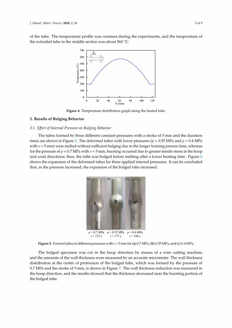
The temperature distribution along the heated tube was measured by an infrared thermometer,as shown in Figure 4. The emissivity is calculated by a thermocouple. The tube was heated for 90 sbefore bulging to increase the temperature and to achieve a steady-state condition. The temperaturedistribution was measured by the moving sensor. The scanning time of the temperature distributionwas about 6 s along the tube. It should be noted that the surface between the tube and the sealingcomponents was assumed to be at a constant temperature (about 200 ◦C). The temperature distributionof the tube was not constant on the surface of the tube, which indicated that the temperature was variedalong the tube. The varied temperature distribution is a positive factor in dieless forming to controlthe heating portion during and after the bulging of aluminum alloys. The temperature of the middle ofthe tube, which was heated directly by the fixed flame, was higher than in the other sections. Propanegas was used as the fuel of the flame heating, and the flame was set within 200 mm of the center
J. Manuf. Mater. Process. 2020, 4, 56 5 of 9
of the tube. The temperature profile was constant during the experiments, and the temperature ofthe extruded tube in the middle section was about 560 ◦C.J. Manuf. Mater. Process. 2020, 4, x FOR PEER REVIEW 5 of 9
Figure 4. Temperature distribution graph along the heated tube.
3. Results of Bulging Behavior
3.1. Effect of Internal Pressure on Bulging Behavior
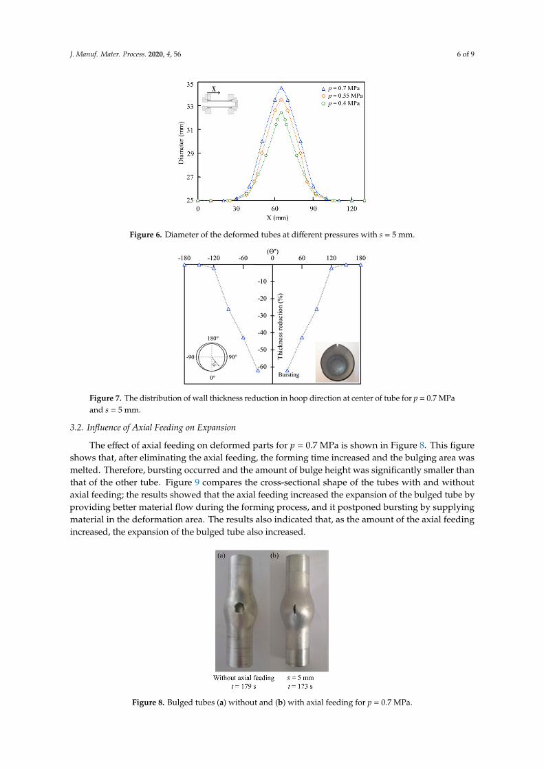
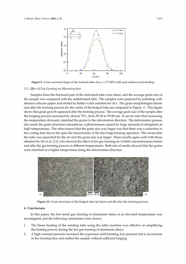
The tubes formed by three different constant pressures with a stroke of 5 mm and the duration times are shown in Figure 5. The deformed tubes with lower pressures (p = 0.55 MPa and p = 0.4 MPa with s = 5 mm) were melted without sufficient bulging due to the longer forming process time, whereas for the pressure of p = 0.7 MPa with s = 5 mm, bursting occurred due to greater tensile stress in the hoop and axial directions; thus, the tube was bulged before melting after a lower heating time. Figure 6 shows the expansion of the deformed tubes for three applied internal pressures. It can be concluded that, as the pressure increased, the expansion of the bulged tube increased.
Figure 5. Formed tubes in different pressures with s = 5 mm for (a) 0.7 MPa, (b) 0.55 MPa, and (c) 0.4 MPa.
Figure 6. Diameter of the deformed tubes at different pressures with s = 5 mm.
Figure 4. Temperature distribution graph along the heated tube.
3. Results of Bulging Behavior
3.1. Effect of Internal Pressure on Bulging Behavior
The tubes formed by three different constant pressures with a stroke of 5 mm and the durationtimes are shown in Figure 5. The deformed tubes with lower pressures (p = 0.55 MPa and p = 0.4 MPawith s = 5 mm) were melted without sufficient bulging due to the longer forming process time, whereasfor the pressure of p = 0.7 MPa with s = 5 mm, bursting occurred due to greater tensile stress in the hoopand axial directions; thus, the tube was bulged before melting after a lower heating time. Figure 6shows the expansion of the deformed tubes for three applied internal pressures. It can be concludedthat, as the pressure increased, the expansion of the bulged tube increased.
J. Manuf. Mater. Process. 2020, 4, x FOR PEER REVIEW 5 of 9
Figure 4. Temperature distribution graph along the heated tube.
3. Results of Bulging Behavior
3.1. Effect of Internal Pressure on Bulging Behavior
The tubes formed by three different constant pressures with a stroke of 5 mm and the duration times are shown in Figure 5. The deformed tubes with lower pressures (p = 0.55 MPa and p = 0.4 MPa with s = 5 mm) were melted without sufficient bulging due to the longer forming process time, whereas for the pressure of p = 0.7 MPa with s = 5 mm, bursting occurred due to greater tensile stress in the hoop and axial directions; thus, the tube was bulged before melting after a lower heating time. Figure 6 shows the expansion of the deformed tubes for three applied internal pressures. It can be concluded that, as the pressure increased, the expansion of the bulged tube increased.
Figure 5. Formed tubes in different pressures with s = 5 mm for (a) 0.7 MPa, (b) 0.55 MPa, and (c) 0.4 MPa.
Figure 6. Diameter of the deformed tubes at different pressures with s = 5 mm.
Figure 5. Formed tubes in different pressures with s = 5 mm for (a) 0.7 MPa, (b) 0.55 MPa, and (c) 0.4 MPa.
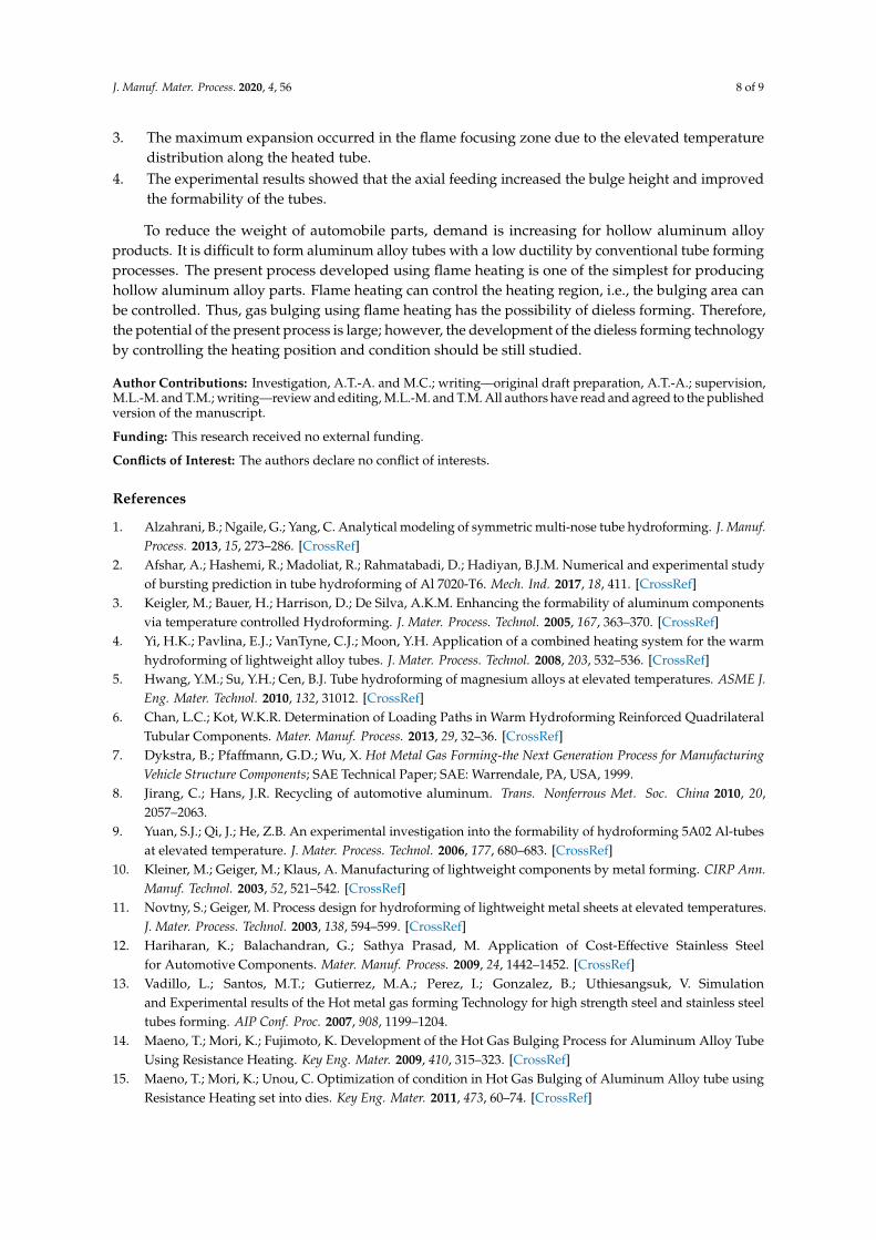
The bulged specimen was cut in the hoop direction by means of a wire cutting machine,and the amounts of the wall thickness were measured by an accurate micrometer. The wall thicknessdistribution at the center of protrusion of the bulged tube, which was formed by the pressure of0.7 MPa and the stroke of 5 mm, is shown in Figure 7. The wall thickness reduction was measured inthe hoop direction, and the results showed that the thickness decreased near the bursting portion ofthe bulged tube.
J. Manuf. Mater. Process. 2020, 4, 56 6 of 9
J. Manuf. Mater. Process. 2020, 4, x FOR PEER REVIEW 5 of 9
Figure 4. Temperature distribution graph along the heated tube.
3. Results of Bulging Behavior
3.1. Effect of Internal Pressure on Bulging Behavior
The tubes formed by three different constant pressures with a stroke of 5 mm and the duration times are shown in Figure 5. The deformed tubes with lower pressures (p = 0.55 MPa and p = 0.4 MPa with s = 5 mm) were melted without sufficient bulging due to the longer forming process time, whereas for the pressure of p = 0.7 MPa with s = 5 mm, bursting occurred due to greater tensile stress in the hoop and axial directions; thus, the tube was bulged before melting after a lower heating time. Figure 6 shows the expansion of the deformed tubes for three applied internal pressures. It can be concluded that, as the pressure increased, the expansion of the bulged tube increased.
Figure 5. Formed tubes in different pressures with s = 5 mm for (a) 0.7 MPa, (b) 0.55 MPa, and (c) 0.4 MPa.
Figure 6. Diameter of the deformed tubes at different pressures with s = 5 mm.
Figure 6. Diameter of the deformed tubes at different pressures with s = 5 mm.
J. Manuf. Mater. Process. 2020, 4, x FOR PEER REVIEW 6 of 9
The bulged specimen was cut in the hoop direction by means of a wire cutting machine, and the amounts of the wall thickness were measured by an accurate micrometer. The wall thickness distribution at the center of protrusion of the bulged tube, which was formed by the pressure of 0.7 MPa and the stroke of 5 mm, is shown in Figure 7. The wall thickness reduction was measured in the hoop direction, and the results showed that the thickness decreased near the bursting portion of the bulged tube.
Figure 7. The distribution of wall thickness reduction in hoop direction at center of tube for p = 0.7 MPa and s = 5 mm.
3.2. Influence of Axial Feeding on Expansion
The effect of axial feeding on deformed parts for p = 0.7 MPa is shown in Figure 8. This figure shows that, after eliminating the axial feeding, the forming time increased and the bulging area was melted. Therefore, bursting occurred and the amount of bulge height was significantly smaller than that of the other tube. Figure 9 compares the cross-sectional shape of the tubes with and without axial feeding; the results showed that the axial feeding increased the expansion of the bulged tube by providing better material flow during the forming process, and it postponed bursting by supplying material in the deformation area. The results also indicated that, as the amount of the axial feeding increased, the expansion of the bulged tube also increased.
Figure 8. Bulged tubes (a) without and (b) with axial feeding for p = 0.7 MPa.
Figure 7. The distribution of wall thickness reduction in hoop direction at center of tube for p = 0.7 MPaand s = 5 mm.
3.2. Influence of Axial Feeding on Expansion
The effect of axial feeding on deformed parts for p = 0.7 MPa is shown in Figure 8. This figureshows that, after eliminating the axial feeding, the forming time increased and the bulging area wasmelted. Therefore, bursting occurred and the amount of bulge height was significantly smaller thanthat of the other tube. Figure 9 compares the cross-sectional shape of the tubes with and withoutaxial feeding; the results showed that the axial feeding increased the expansion of the bulged tube byproviding better material flow during the forming process, and it postponed bursting by supplyingmaterial in the deformation area. The results also indicated that, as the amount of the axial feedingincreased, the expansion of the bulged tube also increased.
J. Manuf. Mater. Process. 2020, 4, x FOR PEER REVIEW 6 of 9
The bulged specimen was cut in the hoop direction by means of a wire cutting machine, and the amounts of the wall thickness were measured by an accurate micrometer. The wall thickness distribution at the center of protrusion of the bulged tube, which was formed by the pressure of 0.7 MPa and the stroke of 5 mm, is shown in Figure 7. The wall thickness reduction was measured in the hoop direction, and the results showed that the thickness decreased near the bursting portion of the bulged tube.
Figure 7. The distribution of wall thickness reduction in hoop direction at center of tube for p = 0.7 MPa and s = 5 mm.
3.2. Influence of Axial Feeding on Expansion
The effect of axial feeding on deformed parts for p = 0.7 MPa is shown in Figure 8. This figure shows that, after eliminating the axial feeding, the forming time increased and the bulging area was melted. Therefore, bursting occurred and the amount of bulge height was significantly smaller than that of the other tube. Figure 9 compares the cross-sectional shape of the tubes with and without axial feeding; the results showed that the axial feeding increased the expansion of the bulged tube by providing better material flow during the forming process, and it postponed bursting by supplying material in the deformation area. The results also indicated that, as the amount of the axial feeding increased, the expansion of the bulged tube also increased.
Figure 8. Bulged tubes (a) without and (b) with axial feeding for p = 0.7 MPa. Figure 8. Bulged tubes (a) without and (b) with axial feeding for p = 0.7 MPa.
J. Manuf. Mater. Process. 2020, 4, 56 7 of 9J. Manuf. Mater. Process. 2020, 4, x FOR PEER REVIEW 7 of 9
Figure 9. Cross-sectional shape of the formed tubes for p = 0.7 MPa with and without axial feeding.
3.3. Effect of Gas Forming on Microstructure
Samples from the fractured part of the deformed tube were taken, and the average grain size of the sample was compared with the undeformed tube. The samples were prepared by polishing with abrasive silicone paper and etched by Keller’s etch solution for 10 s. The grain morphologies before and after the forming process for the center of the bulged tube are compared in Figure 10. This figure shows that grain growth appeared after the forming process. The average grain size of the sample after the bulging process increased by almost 73%, from 55.36 to 95.88 µm. It can be seen that increasing the temperature obviously stretched the grains in the deformation direction. The deformation process also made the grain structures amorphous, a phenomenon caused by large amounts of elongation at high temperatures. The other reason that the grain size was larger was that there was a reduction in the cooling time due to the open die characteristic of the free bulge forming operation. This means that the tube was quenched by the air and the grain size was larger. These results agree well with those obtained by He et al. [23], who showed the effect of hot gas forming on AA6061 microstructures before and after the gas forming process at different temperatures. Both sets of results showed that the grains were stretched at a higher temperature along the deformation direction.
Figure 10. Grain structures of the bulged tube (a) before and (b) after the forming process.
4. Conclusions
In this paper, the hot metal gas forming of aluminum tubes at an elevated temperature was investigated, and the following conclusions were drawn:
1. The flame heating of the rotating tube using the lathe machine was effective at simplifying the heating process during the hot gas forming of aluminum alloys.
2. A high constant pressure increased the expansion until bursting; low pressure led to an increase in the forming time and melted the sample without sufficient bulging.
Figure 9. Cross-sectional shape of the formed tubes for p = 0.7 MPa with and without axial feeding.
3.3. Effect of Gas Forming on Microstructure
Samples from the fractured part of the deformed tube were taken, and the average grain size ofthe sample was compared with the undeformed tube. The samples were prepared by polishing withabrasive silicone paper and etched by Keller’s etch solution for 10 s. The grain morphologies beforeand after the forming process for the center of the bulged tube are compared in Figure 10. This figureshows that grain growth appeared after the forming process. The average grain size of the sample afterthe bulging process increased by almost 73%, from 55.36 to 95.88 µm. It can be seen that increasingthe temperature obviously stretched the grains in the deformation direction. The deformation processalso made the grain structures amorphous, a phenomenon caused by large amounts of elongation athigh temperatures. The other reason that the grain size was larger was that there was a reduction inthe cooling time due to the open die characteristic of the free bulge forming operation. This means thatthe tube was quenched by the air and the grain size was larger. These results agree well with thoseobtained by He et al. [23], who showed the effect of hot gas forming on AA6061 microstructures beforeand after the gas forming process at different temperatures. Both sets of results showed that the grainswere stretched at a higher temperature along the deformation direction.
J. Manuf. Mater. Process. 2020, 4, x FOR PEER REVIEW 7 of 9
Figure 9. Cross-sectional shape of the formed tubes for p = 0.7 MPa with and without axial feeding.
3.3. Effect of Gas Forming on Microstructure
Samples from the fractured part of the deformed tube were taken, and the average grain size of the sample was compared with the undeformed tube. The samples were prepared by polishing with abrasive silicone paper and etched by Keller’s etch solution for 10 s. The grain morphologies before and after the forming process for the center of the bulged tube are compared in Figure 10. This figure shows that grain growth appeared after the forming process. The average grain size of the sample after the bulging process increased by almost 73%, from 55.36 to 95.88 µm. It can be seen that increasing the temperature obviously stretched the grains in the deformation direction. The deformation process also made the grain structures amorphous, a phenomenon caused by large amounts of elongation at high temperatures. The other reason that the grain size was larger was that there was a reduction in the cooling time due to the open die characteristic of the free bulge forming operation. This means that the tube was quenched by the air and the grain size was larger. These results agree well with those obtained by He et al. [23], who showed the effect of hot gas forming on AA6061 microstructures before and after the gas forming process at different temperatures. Both sets of results showed that the grains were stretched at a higher temperature along the deformation direction.
Figure 10. Grain structures of the bulged tube (a) before and (b) after the forming process.
4. Conclusions
In this paper, the hot metal gas forming of aluminum tubes at an elevated temperature was investigated, and the following conclusions were drawn:
1. The flame heating of the rotating tube using the lathe machine was effective at simplifying the heating process during the hot gas forming of aluminum alloys.
2. A high constant pressure increased the expansion until bursting; low pressure led to an increase in the forming time and melted the sample without sufficient bulging.
Figure 10. Grain structures of the bulged tube (a) before and (b) after the forming process.
4. Conclusions
In this paper, the hot metal gas forming of aluminum tubes at an elevated temperature wasinvestigated, and the following conclusions were drawn:
1. The flame heating of the rotating tube using the lathe machine was effective at simplifyingthe heating process during the hot gas forming of aluminum alloys.
2. A high constant pressure increased the expansion until bursting; low pressure led to an increasein the forming time and melted the sample without sufficient bulging.
J. Manuf. Mater. Process. 2020, 4, 56 8 of 9
3. The maximum expansion occurred in the flame focusing zone due to the elevated temperaturedistribution along the heated tube.
4. The experimental results showed that the axial feeding increased the bulge height and improvedthe formability of the tubes.
To reduce the weight of automobile parts, demand is increasing for hollow aluminum alloyproducts. It is difficult to form aluminum alloy tubes with a low ductility by conventional tube formingprocesses. The present process developed using flame heating is one of the simplest for producinghollow aluminum alloy parts. Flame heating can control the heating region, i.e., the bulging area canbe controlled. Thus, gas bulging using flame heating has the possibility of dieless forming. Therefore,the potential of the present process is large; however, the development of the dieless forming technologyby controlling the heating position and condition should be still studied.
Author Contributions: Investigation, A.T.-A. and M.C.; writing—original draft preparation, A.T.-A.; supervision,M.L.-M. and T.M.; writing—review and editing, M.L.-M. and T.M. All authors have read and agreed to the publishedversion of the manuscript.
Funding: This research received no external funding.
Conflicts of Interest: The authors declare no conflict of interests.
References
1. Alzahrani, B.; Ngaile, G.; Yang, C. Analytical modeling of symmetric multi-nose tube hydroforming. J. Manuf.Process. 2013, 15, 273–286. [CrossRef]
2. Afshar, A.; Hashemi, R.; Madoliat, R.; Rahmatabadi, D.; Hadiyan, B.J.M. Numerical and experimental studyof bursting prediction in tube hydroforming of Al 7020-T6. Mech. Ind. 2017, 18, 411. [CrossRef]
3. Keigler, M.; Bauer, H.; Harrison, D.; De Silva, A.K.M. Enhancing the formability of aluminum componentsvia temperature controlled Hydroforming. J. Mater. Process. Technol. 2005, 167, 363–370. [CrossRef]
4. Yi, H.K.; Pavlina, E.J.; VanTyne, C.J.; Moon, Y.H. Application of a combined heating system for the warmhydroforming of lightweight alloy tubes. J. Mater. Process. Technol. 2008, 203, 532–536. [CrossRef]
5. Hwang, Y.M.; Su, Y.H.; Cen, B.J. Tube hydroforming of magnesium alloys at elevated temperatures. ASME J.Eng. Mater. Technol. 2010, 132, 31012. [CrossRef]
6. Chan, L.C.; Kot, W.K.R. Determination of Loading Paths in Warm Hydroforming Reinforced QuadrilateralTubular Components. Mater. Manuf. Process. 2013, 29, 32–36. [CrossRef]
7. Dykstra, B.; Pfaffmann, G.D.; Wu, X. Hot Metal Gas Forming-the Next Generation Process for ManufacturingVehicle Structure Components; SAE Technical Paper; SAE: Warrendale, PA, USA, 1999.
8. Jirang, C.; Hans, J.R. Recycling of automotive aluminum. Trans. Nonferrous Met. Soc. China 2010, 20,2057–2063.
9. Yuan, S.J.; Qi, J.; He, Z.B. An experimental investigation into the formability of hydroforming 5A02 Al-tubesat elevated temperature. J. Mater. Process. Technol. 2006, 177, 680–683. [CrossRef]
10. Kleiner, M.; Geiger, M.; Klaus, A. Manufacturing of lightweight components by metal forming. CIRP Ann.Manuf. Technol. 2003, 52, 521–542. [CrossRef]
11. Novtny, S.; Geiger, M. Process design for hydroforming of lightweight metal sheets at elevated temperatures.J. Mater. Process. Technol. 2003, 138, 594–599. [CrossRef]
12. Hariharan, K.; Balachandran, G.; Sathya Prasad, M. Application of Cost-Effective Stainless Steelfor Automotive Components. Mater. Manuf. Process. 2009, 24, 1442–1452. [CrossRef]
13. Vadillo, L.; Santos, M.T.; Gutierrez, M.A.; Perez, I.; Gonzalez, B.; Uthiesangsuk, V. Simulationand Experimental results of the Hot metal gas forming Technology for high strength steel and stainless steeltubes forming. AIP Conf. Proc. 2007, 908, 1199–1204.
14. Maeno, T.; Mori, K.; Fujimoto, K. Development of the Hot Gas Bulging Process for Aluminum Alloy TubeUsing Resistance Heating. Key Eng. Mater. 2009, 410, 315–323. [CrossRef]
15. Maeno, T.; Mori, K.; Unou, C. Optimization of condition in Hot Gas Bulging of Aluminum Alloy tube usingResistance Heating set into dies. Key Eng. Mater. 2011, 473, 60–74. [CrossRef]
J. Manuf. Mater. Process. 2020, 4, 56 9 of 9
16. He, Z.B.; Teng, B.G.; Che, C.Y.; Wang, Z.B.; Zheng, K.L.; Yuan, S.J. Mechanical properties and formability ofTA2 extrude tube for hot metal gas forming at elevated temperature. Trans. Nonferrous Met. Soc. China 2012,22, s479–s484. [CrossRef]
17. Maeno, T.; Mori, K.; Adachi, K. Gas forming of ultra-high strength steel hollow part using air filled intosealed tube and resistance heating. J. Mater. Process. Technol. 2014, 214, 97–105. [CrossRef]
18. Liu, G.; Wua, Y.; Zhaoa, J.; Wanga, K.; Yuana, S. Formability determination of titanium alloy tube for highpressure pneumatic forming at elevated temperature. Procedia Eng. 2014, 81, 2243–2248. [CrossRef]
19. Paul, A.; Strano, M. The Influence of Process Variables on the Gas Forming and press Hardening of SteelTubes. J. Mater. Process. Technol. 2015, 228, 160–169. [CrossRef]
20. Talebi Anaraki, A.; Loh-Mousavi, M.; Wang, L.-L. Experimental and numerical investigation of the influenceof pulsating pressure on hot tube gas forming using oscillating heating. Int. J. Adv. Manuf. Technol. 2018, 97,3839–3848. [CrossRef]
21. Hwang, Y.M.; Kuo, T.Y. Dieless drawing of stainless steel tubes. Int. J. Adv. Manuf. Technol. 2013, 68,1311–1316. [CrossRef]
22. Furushima, T.; Manabe, K. Experimental and numerical study on deformation behavior in dieless drawingprocess of superplastic microtubes. J. Mater. Process. Technol. 2007, 191, 59–63. [CrossRef]
23. He, Z.B.; Fan, X.B.; Shao, F.; Zheng, K.L.; Wang, Z.B.; Yuan, S.J. Formability and Microstructure of AA6061 AlAlloy Tube for Hot Metal Gas Forming at Elevated Temperature. Trans. Nonferrous Met. Soc. China 2012, 22,s364–s369. [CrossRef]
© 2020 by the authors. Licensee MDPI, Basel, Switzerland. This article is an open accessarticle distributed under the terms and conditions of the Creative Commons Attribution(CC BY) license (http://creativecommons.org/licenses/by/4.0/).