Embed Size (px)
Citation preview
* Technical contribution to the 46º Seminário de Redução de Minério de Ferro e Matérias-primas, to 17º Simpósio Brasileiro de Minério de Ferro and to 4º Simpósio Brasileiro de Aglomeração de Minério de Ferro, part of the ABM Week, September 26th-30th, 2016, Rio de Janeiro, RJ, Brazil.
HOT BLAST AIR DISTRIBUTION MAIN DESIGN MODIFICATIONS FOR IMPROVED PERFORMANCE*
Kyle T. Chomyn1
Salustiano M. Pinto2
Matthew E. DeGorter 3
Adam D. Blackmore 4 John W. Busser5
Hamid R. Ghorbani6 Abstract Multi-disciplinary engineering analysis and advanced modeling techniques were used to identify and develop low cost design modifications to improve a blast furnace hot blast air distribution main that experienced frequent refractory failures. Piping flexibility analysis helped identify the root causes of refractory damage and determine the need for new expansion joints. Finite element analysis was used to optimize a custom-designed elbow-to-elbow tie-rod system, which ensures thermal expansion loads are not placed on connecting piping. Heat transfer coefficients through the elbows were estimated using computational fluid dynamics (CFD) flow modeling. The cast refractory design was changed to a more reliable brick refractory design. Excessive draft was occurring during furnace back-drafting, so the system was assessed using CFD, and a passive flow-reduction spool was designed. This first-principles engineering design approach allowed for optimization and verification, ensuring that the new design addressed the root cause of the previous deficiencies. Keywords: Finite element analysis; Computational fluid dynamics; Piping flexibility analysis; Refractory design. 1 Bachelors of Applied Science, Senior Engineer, Specialized Engineering Analysis & Design, Hatch
Ltd, Mississauga, Ontario, Canada. 2 Masters of Engineering, Engineering, ArcelorMittal Monlevade, Belo Horizonte, Minas Gerais,
Brazil. 3 Bachelors of Applied Science, Refractory Engineer, Furnace Group, Hatch Ltd, Mississauga,
Ontario, Canada. 4 Masters of Applied Science, Engineer, Specialized Engineering Analysis & Design, Hatch Ltd,
Mississauga, Ontario, Canada. 5 Bachelors of Applied Science, Masters of Business Administration, Project Manager, Iron & Steel,
Hatch Ltd, Mississauga, Ontario, Canada. 6 PhD Mechanical Engineering, Practice Lead, Specialized Engineering Analysis & Design, Hatch
Ltd, Mississauga, Ontario, Canada.
27
ISSN 1983-4764
* Technical contribution to the 46º Seminário de Redução de Minério de Ferro e Matérias-primas, to 17º Simpósio Brasileiro de Minério de Ferro and to 4º Simpósio Brasileiro de Aglomeração de Minério de Ferro, part of the ABM Week, September 26th-30th, 2016, Rio de Janeiro, RJ, Brazil.
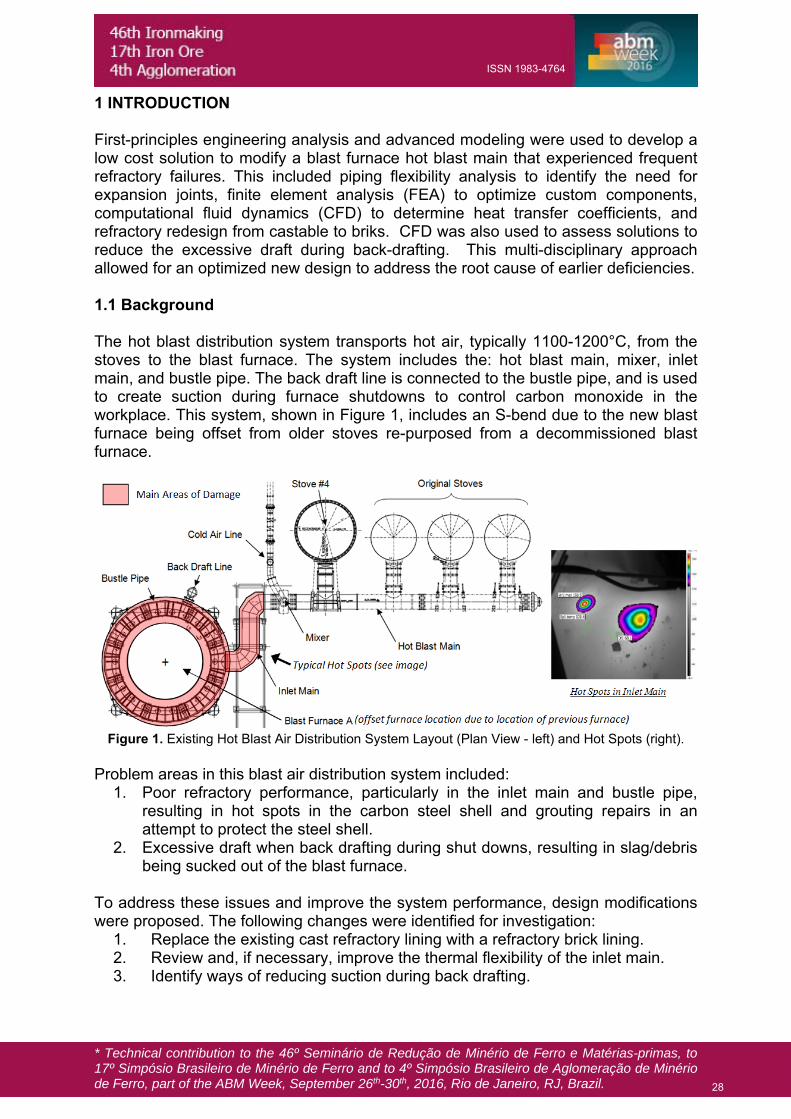
1 INTRODUCTION First-principles engineering analysis and advanced modeling were used to develop a low cost solution to modify a blast furnace hot blast main that experienced frequent refractory failures. This included piping flexibility analysis to identify the need for expansion joints, finite element analysis (FEA) to optimize custom components, computational fluid dynamics (CFD) to determine heat transfer coefficients, and refractory redesign from castable to briks. CFD was also used to assess solutions to reduce the excessive draft during back-drafting. This multi-disciplinary approach allowed for an optimized new design to address the root cause of earlier deficiencies. 1.1 Background The hot blast distribution system transports hot air, typically 1100-1200°C, from the stoves to the blast furnace. The system includes the: hot blast main, mixer, inlet main, and bustle pipe. The back draft line is connected to the bustle pipe, and is used to create suction during furnace shutdowns to control carbon monoxide in the workplace. This system, shown in Figure 1, includes an S-bend due to the new blast furnace being offset from older stoves re-purposed from a decommissioned blast furnace.
Figure 1. Existing Hot Blast Air Distribution System Layout (Plan View - left) and Hot Spots (right).
Problem areas in this blast air distribution system included:
1. Poor refractory performance, particularly in the inlet main and bustle pipe, resulting in hot spots in the carbon steel shell and grouting repairs in an attempt to protect the steel shell.
2. Excessive draft when back drafting during shut downs, resulting in slag/debris being sucked out of the blast furnace.
To address these issues and improve the system performance, design modifications were proposed. The following changes were identified for investigation:
1. Replace the existing cast refractory lining with a refractory brick lining. 2. Review and, if necessary, improve the thermal flexibility of the inlet main. 3. Identify ways of reducing suction during back drafting.
28
ISSN 1983-4764
* Technical contribution to the 46º Seminário de Redução de Minério de Ferro e Matérias-primas, to 17º Simpósio Brasileiro de Minério de Ferro and to 4º Simpósio Brasileiro de Aglomeração de Minério de Ferro, part of the ABM Week, September 26th-30th, 2016, Rio de Janeiro, RJ, Brazil.
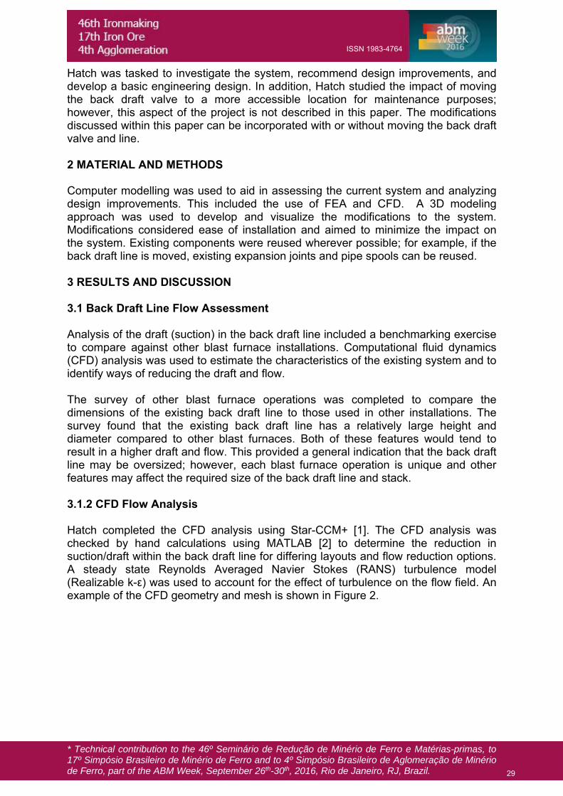
Hatch was tasked to investigate the system, recommend design improvements, and develop a basic engineering design. In addition, Hatch studied the impact of moving the back draft valve to a more accessible location for maintenance purposes; however, this aspect of the project is not described in this paper. The modifications discussed within this paper can be incorporated with or without moving the back draft valve and line. 2 MATERIAL AND METHODS Computer modelling was used to aid in assessing the current system and analyzing design improvements. This included the use of FEA and CFD. A 3D modeling approach was used to develop and visualize the modifications to the system. Modifications considered ease of installation and aimed to minimize the impact on the system. Existing components were reused wherever possible; for example, if the back draft line is moved, existing expansion joints and pipe spools can be reused. 3 RESULTS AND DISCUSSION 3.1 Back Draft Line Flow Assessment Analysis of the draft (suction) in the back draft line included a benchmarking exercise to compare against other blast furnace installations. Computational fluid dynamics (CFD) analysis was used to estimate the characteristics of the existing system and to identify ways of reducing the draft and flow. The survey of other blast furnace operations was completed to compare the dimensions of the existing back draft line to those used in other installations. The survey found that the existing back draft line has a relatively large height and diameter compared to other blast furnaces. Both of these features would tend to result in a higher draft and flow. This provided a general indication that the back draft line may be oversized; however, each blast furnace operation is unique and other features may affect the required size of the back draft line and stack. 3.1.2 CFD Flow Analysis Hatch completed the CFD analysis using Star-CCM+ [1]. The CFD analysis was checked by hand calculations using MATLAB [2] to determine the reduction in suction/draft within the back draft line for differing layouts and flow reduction options. A steady state Reynolds Averaged Navier Stokes (RANS) turbulence model (Realizable k-ε) was used to account for the effect of turbulence on the flow field. An example of the CFD geometry and mesh is shown in Figure 2.
29
ISSN 1983-4764

* Technical contribution to the 46º Seminário de Redução de Minério de Ferro e Matérias-primas, to 17º Simpósio Brasileiro de Minério de Ferro and to 4º Simpósio Brasileiro de Aglomeração de Minério de Ferro, part of the ABM Week, September 26th-30th, 2016, Rio de Janeiro, RJ, Brazil.
Figure 2. Typical Velocity Results with Flow Reduction Spool (left), and Reduction Spool (right).
Flow reduction options considered included active systems, such as a back draft control valve, a control damper, or steam injection; and passive systems, such as flow restriction or reducing the stack height. A passive control technology was selected for further study, as it is intrinsically safer and has less impact on operations and maintenance. CFD was used to size two different flow reduction spools in order to achieve either a low pressure drop or a moderate pressure drop, as shown in Table 1. Typical reduction spool geometry is shown in Figure 2. The main pressure drop is achieved at the sudden transition back to the nominal diameter. This provides a more reliable pressure drop compared to an extended section of reduced diameter, which would be highly dependent on the surface roughness. A suitable location within the back draft stack was identified to allow for easy installation of the flow reduction spool, which would replace an existing stack piece.
Table 1. Effect of Flow Reduction Spools with Existing Back Draft Line Layout.
Reduction Spool Scenario Draft ∆% Flow ∆%
Low Pressure Drop -23% -12%
Moderate Pressure Drop -33% -19%
3.2 Piping Flexibility Analysis A piping flexibility analysis was performed to assess the flexibility of the system and resulting thermal loads during expansion. The analysis was done using Strand7 [3] FEA software. A number of cases were investigated, including the existing design and a revised design to improve flexibility.
30
ISSN 1983-4764
* Technical contribution to the 46º Seminário de Redução de Minério de Ferro e Matérias-primas, to 17º Simpósio Brasileiro de Minério de Ferro and to 4º Simpósio Brasileiro de Aglomeração de Minério de Ferro, part of the ABM Week, September 26th-30th, 2016, Rio de Janeiro, RJ, Brazil.
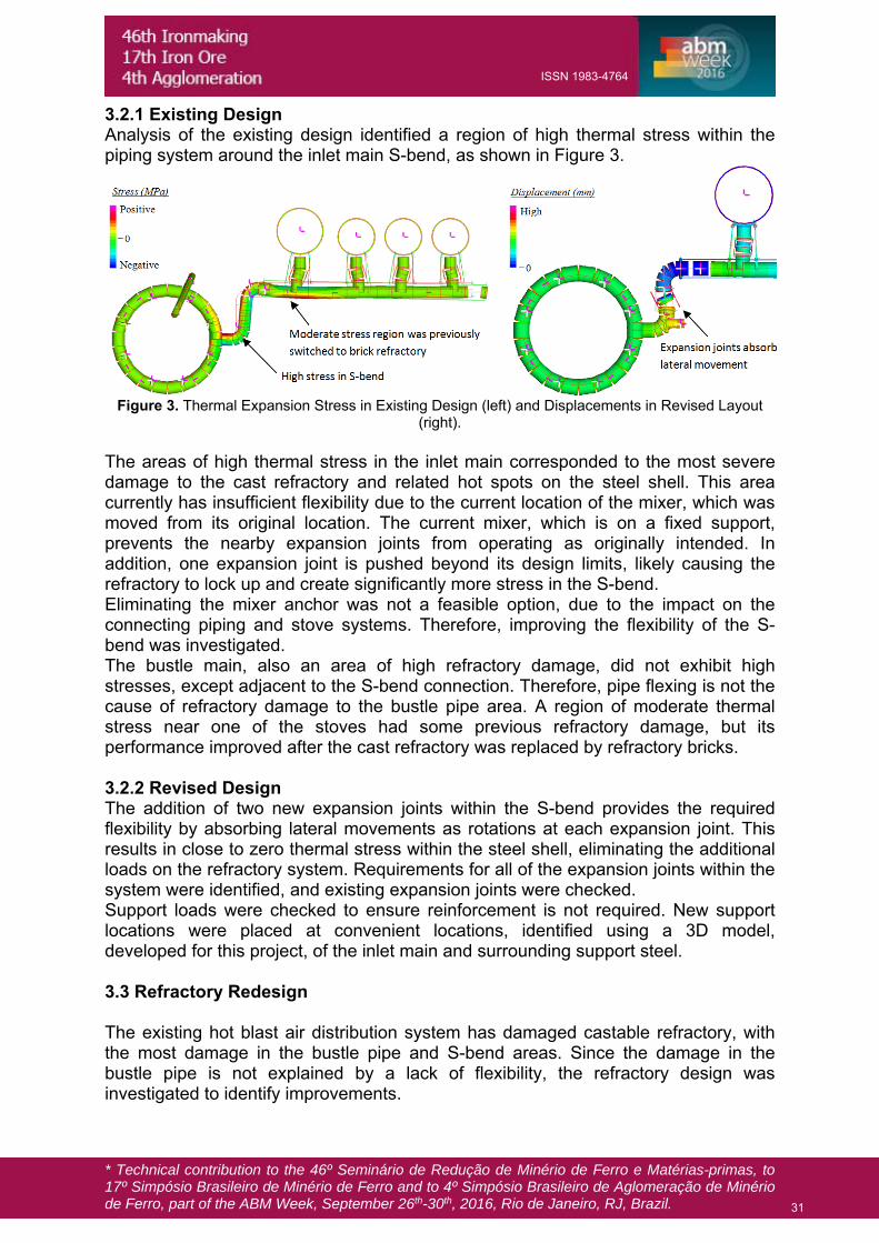
3.2.1 Existing Design Analysis of the existing design identified a region of high thermal stress within the piping system around the inlet main S-bend, as shown in Figure 3.
Figure 3. Thermal Expansion Stress in Existing Design (left) and Displacements in Revised Layout
(right). The areas of high thermal stress in the inlet main corresponded to the most severe damage to the cast refractory and related hot spots on the steel shell. This area currently has insufficient flexibility due to the current location of the mixer, which was moved from its original location. The current mixer, which is on a fixed support, prevents the nearby expansion joints from operating as originally intended. In addition, one expansion joint is pushed beyond its design limits, likely causing the refractory to lock up and create significantly more stress in the S-bend. Eliminating the mixer anchor was not a feasible option, due to the impact on the connecting piping and stove systems. Therefore, improving the flexibility of the S-bend was investigated. The bustle main, also an area of high refractory damage, did not exhibit high stresses, except adjacent to the S-bend connection. Therefore, pipe flexing is not the cause of refractory damage to the bustle pipe area. A region of moderate thermal stress near one of the stoves had some previous refractory damage, but its performance improved after the cast refractory was replaced by refractory bricks. 3.2.2 Revised Design The addition of two new expansion joints within the S-bend provides the required flexibility by absorbing lateral movements as rotations at each expansion joint. This results in close to zero thermal stress within the steel shell, eliminating the additional loads on the refractory system. Requirements for all of the expansion joints within the system were identified, and existing expansion joints were checked. Support loads were checked to ensure reinforcement is not required. New support locations were placed at convenient locations, identified using a 3D model, developed for this project, of the inlet main and surrounding support steel. 3.3 Refractory Redesign The existing hot blast air distribution system has damaged castable refractory, with the most damage in the bustle pipe and S-bend areas. Since the damage in the bustle pipe is not explained by a lack of flexibility, the refractory design was investigated to identify improvements.
31
ISSN 1983-4764
* Technical contribution to the 46º Seminário de Redução de Minério de Ferro e Matérias-primas, to 17º Simpósio Brasileiro de Minério de Ferro and to 4º Simpósio Brasileiro de Aglomeração de Minério de Ferro, part of the ABM Week, September 26th-30th, 2016, Rio de Janeiro, RJ, Brazil.
The first proposed change was to switch from an all castable refractory design to a refractory brick design. Refractory brick offers a range of performance advantages over castable refractory: A finished product is supplied – the properties are known, whereas castable
refractory relies on the installation procedure. The brick refractory system is more flexible and better able to absorb thermal
expansion, particularly if a relatively soft mortar is used, and expansion joints tend to be more reliable / predictable.
Bricks typically have better long-term performance, leading to a longer service life, and any damage is more effectively repaired.
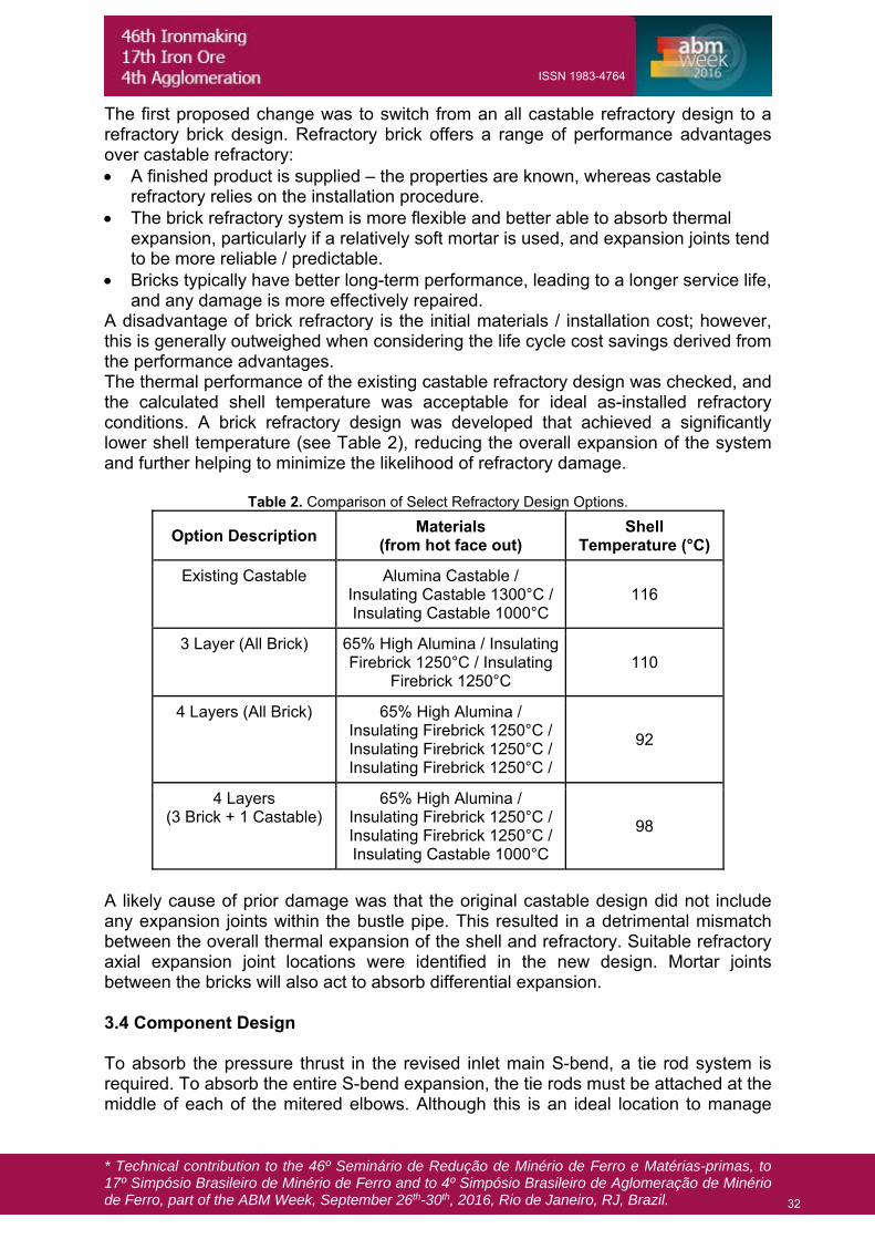
A disadvantage of brick refractory is the initial materials / installation cost; however, this is generally outweighed when considering the life cycle cost savings derived from the performance advantages. The thermal performance of the existing castable refractory design was checked, and the calculated shell temperature was acceptable for ideal as-installed refractory conditions. A brick refractory design was developed that achieved a significantly lower shell temperature (see Table 2), reducing the overall expansion of the system and further helping to minimize the likelihood of refractory damage.
Table 2. Comparison of Select Refractory Design Options.
Option Description Materials
(from hot face out) Shell
Temperature (°C)
Existing Castable Alumina Castable / Insulating Castable 1300°C / Insulating Castable 1000°C
116
3 Layer (All Brick) 65% High Alumina / Insulating Firebrick 1250°C / Insulating
Firebrick 1250°C 110
4 Layers (All Brick) 65% High Alumina / Insulating Firebrick 1250°C /Insulating Firebrick 1250°C / Insulating Firebrick 1250°C /
92
4 Layers (3 Brick + 1 Castable)
65% High Alumina / Insulating Firebrick 1250°C / Insulating Firebrick 1250°C / Insulating Castable 1000°C
98
A likely cause of prior damage was that the original castable design did not include any expansion joints within the bustle pipe. This resulted in a detrimental mismatch between the overall thermal expansion of the shell and refractory. Suitable refractory axial expansion joint locations were identified in the new design. Mortar joints between the bricks will also act to absorb differential expansion. 3.4 Component Design To absorb the pressure thrust in the revised inlet main S-bend, a tie rod system is required. To absorb the entire S-bend expansion, the tie rods must be attached at the middle of each of the mitered elbows. Although this is an ideal location to manage
32
ISSN 1983-4764
* Technical contribution to the 46º Seminário de Redução de Minério de Ferro e Matérias-primas, to 17º Simpósio Brasileiro de Minério de Ferro and to 4º Simpósio Brasileiro de Aglomeração de Minério de Ferro, part of the ABM Week, September 26th-30th, 2016, Rio de Janeiro, RJ, Brazil.
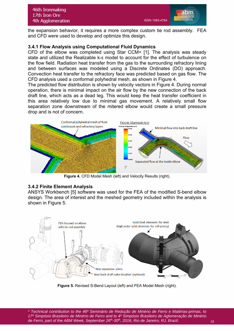
the expansion behavior, it requires a more complex custom tie rod assembly. FEA and CFD were used to develop and optimize this design. 3.4.1 Flow Analysis using Computational Fluid Dynamics CFD of the elbow was completed using Star CCM+ [1]. The analysis was steady state and utilized the Realizable k-ε model to account for the effect of turbulence on the flow field. Radiation heat transfer from the gas to the surrounding refractory lining and between surfaces was modeled using a Discrete Ordinates (DO) approach. Convection heat transfer to the refractory face was predicted based on gas flow. The CFD analysis used a conformal polyhedral mesh, as shown in Figure 4. The predicted flow distribution is shown by velocity vectors in Figure 4. During normal operation, there is minimal impact on the air flow by the new connection of the back draft line, which acts as a dead leg. This would keep the heat transfer coefficient in this area relatively low due to minimal gas movement. A relatively small flow separation zone downstream of the mitered elbow would create a small pressure drop and is not of concern.
Figure 4. CFD Model Mesh (left) and Velocity Results (right).
3.4.2 Finite Element Analysis ANSYS Workbench [5] software was used for the FEA of the modified S-bend elbow design. The area of interest and the meshed geometry included within the analysis is shown in Figure 5.
Figure 5. Revised S-Bend Layout (left) and FEA Model Mesh (right).
33
ISSN 1983-4764
* Technical contribution to the 46º Seminário de Redução de Minério de Ferro e Matérias-primas, to 17º Simpósio Brasileiro de Minério de Ferro and to 4º Simpósio Brasileiro de Aglomeração de Minério de Ferro, part of the ABM Week, September 26th-30th, 2016, Rio de Janeiro, RJ, Brazil.
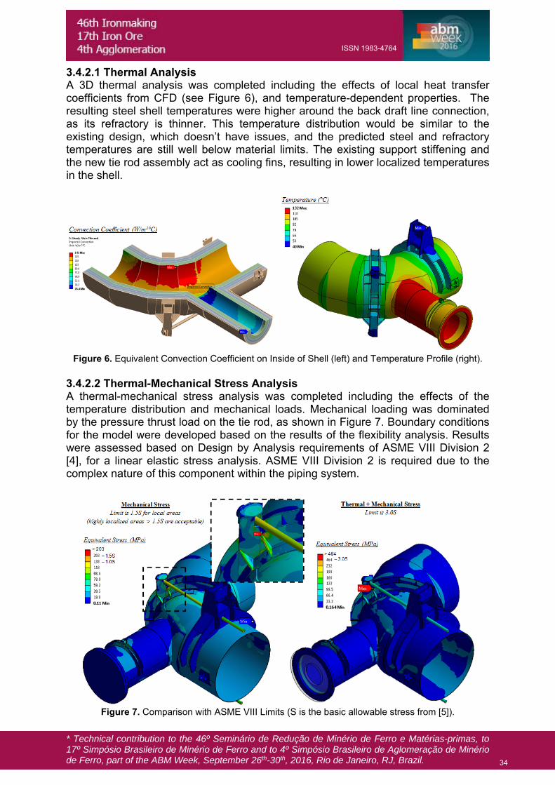
3.4.2.1 Thermal Analysis A 3D thermal analysis was completed including the effects of local heat transfer coefficients from CFD (see Figure 6), and temperature-dependent properties. The resulting steel shell temperatures were higher around the back draft line connection, as its refractory is thinner. This temperature distribution would be similar to the existing design, which doesn’t have issues, and the predicted steel and refractory temperatures are still well below material limits. The existing support stiffening and the new tie rod assembly act as cooling fins, resulting in lower localized temperatures in the shell.
Figure 6. Equivalent Convection Coefficient on Inside of Shell (left) and Temperature Profile (right).
3.4.2.2 Thermal-Mechanical Stress Analysis A thermal-mechanical stress analysis was completed including the effects of the temperature distribution and mechanical loads. Mechanical loading was dominated by the pressure thrust load on the tie rod, as shown in Figure 7. Boundary conditions for the model were developed based on the results of the flexibility analysis. Results were assessed based on Design by Analysis requirements of ASME VIII Division 2 [4], for a linear elastic stress analysis. ASME VIII Division 2 is required due to the complex nature of this component within the piping system.
Figure 7. Comparison with ASME VIII Limits (S is the basic allowable stress from [5]).
34
ISSN 1983-4764

* Technical contribution to the 46º Seminário de Redução de Minério de Ferro e Matérias-primas, to 17º Simpósio Brasileiro de Minério de Ferro and to 4º Simpósio Brasileiro de Aglomeração de Minério de Ferro, part of the ABM Week, September 26th-30th, 2016, Rio de Janeiro, RJ, Brazil.
Initial analyses identified areas of the tie-rod assembly that were either over-stressed or were carrying minimal stress. These areas were modified through several design iterations to provide an optimized solution. Highly localized stresses due to structural discontinuities are classified as secondary or peak [4]. These stresses will redistribute due to localized plasticity and are not cause for concern as the hot blast air distribution system experiences minimal cyclic loading. Thermal stresses were combined with mechanical stresses and checked against the ASME limits for ratcheting [4], and found to be well within limits. This ensured that the tie rod system will not exhibit progressive deformation over its service life. 3.4.2.3 Thermal-Mechanical Deformations Analysis In addition to the strength of the elbow, the deflections of the system were checked to ensure there is not an adverse affect on refractory, due to ovalling or other warping. Limits are not given in ASME code, but excessive warping can result in refractory damage. Hatch’s in-house best practice are based on European code requirements for fabrication tolerances in refractory systems. Ovalling was checked at the most critical sections, as shown in Figure 8. The calculated values were found to be within the limits for a component of this size, confirming the deformations are acceptable.
Figure 8. Exaggerated Deformation (left) and Checking of Out-of-Roundness (right).
4 CONCLUSION A hot blast air distribution system experiencing refractory damage, hot spots, and excessive back draft suction pressure was studied using a multi-disciplinary first-principles engineering analysis. This included CFD analysis of flow within the back draft line, piping flexibility analysis, refractory redesign, and custom design of components using FEA and CFD. A low cost solution was developed for restricting the flow within the back draft line, to minimize the chance of slag being drawn in from the blast furnace. Deficiencies in the piping flexibility between the stoves and bustle pipe were identified, and new expansion joints were added to improve flexibility. A refractory brick design was developed to minimize the use of castable refractory and improve performance. A safe and economical custom tie-rod assembly was developed for use with the new expansion joints. This project highlighted the value of using modern design tools to develop designs in challenging brownfield conditions. The new design will improve the future hot blast air distribution system campaign life with maximized re-use of existing components.
35
ISSN 1983-4764

* Technical contribution to the 46º Seminário de Redução de Minério de Ferro e Matérias-primas, to 17º Simpósio Brasileiro de Minério de Ferro and to 4º Simpósio Brasileiro de Aglomeração de Minério de Ferro, part of the ABM Week, September 26th-30th, 2016, Rio de Janeiro, RJ, Brazil.
REFERENCES 1 Star-CCM. Release 10.02.012 [Computer software]. CD-Adapco, New York, NY. 2 MATLAB. Release 3023b SP1 [Computer software]. MathWorks, Natick, MA. 3 Strand7 Finite Element Analysis System. Release 2.4.5 [Computer software]. Strand7
Pty Ltd, Sydney, Australia. 4 The American Society of Mechanical Engineers, 2015 ASME Boiler and Pressure
Vessel Code Section VIII Division 2, The American Society of Mechanical Engineers, New York, NY, 2015.
5 ANSYS Workbench. Release 16.2. [Computer software]. ANSYS Incm Canonsburg, PA.
36
ISSN 1983-4764


![TOP GAS RECYCLE BLAST FURNACE …...1980s in 12 campaigns by RPA Toulachermet [24] in Russia at blast furnace No. 2 (Volume: 1033 m³). In this all-coke blast furnace concept, hot](https://img.pdfslide.us/doc/110x75/5e6d35c47d175e6b1021e25f/top-gas-recycle-blast-furnace-1980s-in-12-campaigns-by-rpa-toulachermet-24.jpg)


![Use of Hot Metal With High Phosphorous Content in …...blast furnace is naturally converted into the hot metal by 90–100%. The only possibility to limit the [%P] of the hot metal](https://img.pdfslide.us/doc/110x75/5f4652d286652e476d5bee5e/use-of-hot-metal-with-high-phosphorous-content-in-blast-furnace-is-naturally.jpg)