Embed Size (px)
Citation preview

SERVICE MANUAL
ISSUED: JULY. 13, 1999
MODEL
HOSHIZAKIMODULAR FLAKER
F-1000MAF-22C
NO: 73088
DEC. 15, 2003REVISED:

2
HOSHIZAKI AMERICA, INC.618 Highway 74 SouthPeachtree City, GA 30269
Attn: HOSHIZAKI Technical Support Department
Phone: 1-800-233-1940 Technical Service(770) 487-2331
Fax: (770) 487-3360
NOTE: To expedite assistance, all correspondence/communication MUST include the following information:
• Model Number
• Serial Number
• Complete and detailed explanation of the problem
IMPORTANTOnly qualified service technicians should attempt to service or maintain this icemaker.No service or maintenance should be undertaken until the technician hasthoroughly read this Service Manual.
HOSHIZAKI provides this manual primarily to assist qualified service technicians in theservice and maintenance of the icemaker.
Should the reader have any questions or concerns which have not been satisfactorilyaddressed, please call or write to the HOSHIZAKI Technical Support Department forassistance.

3
CONTENTSPAGE
I. SPECIFICATIONS .................................................................................................... 41. ICEMAKER ............................................................................................................. 4
II. GENERAL INFORMATION ...................................................................................... 51. CONSTRUCTION................................................................................................... 52. CONTROL BOX LAYOUT ...................................................................................... 6
III. TECHNICAL INFORMATION .................................................................................. 71. WATER CIRCUIT AND REFRIGERANT CIRCUIT ................................................ 72. WIRING DIAGRAM ................................................................................................ 83. SEQUENCE OF ELECTRICAL CIRCUIT ............................................................... 94. TIMING CHART.................................................................................................... 195. PERFORMANCE DATA ....................................................................................... 22
IV. SERVICE DIAGNOSIS ......................................................................................... 231. NO ICE PRODUCTION ........................................................................................ 232. LOW ICE PRODUCTION ..................................................................................... 253. OTHERS............................................................................................................... 26
V. REMOVAL AND REPLACEMENT OF COMPONENTS ........................................ 271. SERVICE FOR REFRIGERANT LINES ............................................................... 27
[a] REFRIGERANT RECOVERY ......................................................................... 27[b] EVACUATION AND RECHARGE ................................................................... 27
2. BRAZING.............................................................................................................. 283. REMOVAL AND REPLACEMENT OF COMPRESSOR....................................... 294. REMOVAL AND REPLACEMENT OF DRIER ..................................................... 305. REMOVAL AND REPLACEMENT OF EXPANSION VALVE ............................... 316. REMOVAL AND REPLACEMENT OF EVAPORATOR ASSEMBLY ................... 327. REMOVAL AND REPLACEMENT OF FAN MOTOR ........................................... 368. REMOVAL AND REPLACEMENT OF CONTROL WATER VALVE .................... 369. REMOVAL AND REPLACEMENT OF FLUSH WATER VALVE .......................... 37
VII. MAINTENANCE AND CLEANING INSTRUCTIONS ........................................... 381. PREPARING THE ICEMAKER FOR LONG STORAGE ...................................... 382. CLEANING INSTRUCTIONS ............................................................................... 393. MAINTENANCE ................................................................................................... 43
Please review this manual. It should be read carefully before the icemaker is serviced ormaintenance operations are performed. Only qualified service technicians should serviceand maintain the icemaker. This manual should be made available to the technician priorto service or maintenance.

4
I. SPECIFICATION1. ICEMAKER
F-1000MAF-22
We reserve the right to make changes in specifications and design without prior notice.
AC SUPPLY VOLTAGE 208-230/60/1 (3 wire with neutral for 115V) COMPRESSOR 240 V 4.5 RLA 34 LRAGEAR MOTOR 120 V 1.6 FLA 1/6 HPFAN MOTOR 115 V 0.85FLA 1/15 HPOTHER 120 V 0.03AMAXIMUM FUSE SIZE 15 AMAX. HACR BREAKER (USA ONLY) 15 AMAX. CIRC. BREAKER (CANADA ONLY) 15 AMINIMUM CIRCUIT AMPACITY 15 AAPPROXIMATE ICE PRODUCTION Ambient WATER TEMP. (˚F)PER 24 HR. Temp.(˚F) 50 70 90 lbs./day ( kg/day ) 70 *860 (390) 820 (360) 790 (348)Reference without *marks 80 765 (338) 720 (327) 710 (317)
90 680 (307) *670 (304) 635 (288)100 615 (279) 585 (271) *555 (252)
SHAPE OF ICE CubeletICE QUALITY Approx. 80%, Ice (90/70˚F, Conductivity 200 µs/cm)APPROXIMATE STORAGE CAPACITY N/AELECTRIC & WATER CONSUMPTION 90/70˚F 70/50˚F ELECTRIC W (kWH/100 lbs.) 1205 (4.3) 1155 (3.2) POTABLE WATER 80 (12) 103 (12) gal./24HR (gal./100 lbs.)EXTERIOR DIMENSIONS (WxDxH) 22" x 27-3/8" x 25-1/4" (560 x 695 x 642mm)EXTERIOR FINISH Stainless Steel, Galvanized Steel (Rear) WEIGHT Net 172 lbs. ( 78 kg ), Shipping 198 lbs. ( 90 kg )CONNECTIONS - ELECTRIC Permanent - Connection - WATER SUPPLY Inlet 1/2" FPT - DRAIN Outlet 3/4" FPTICE MAKING SYSTEM Auger typeHARVESTING SYSTEM Direct Driven Auger ( 1/6 HP Gear Motor )ICE MAKING WATER CONTROL Float SwitchCOOLING WATER CONTROL N/ABIN CONTROL SYSTEM Mechanical Bin Control ( Proximity Sw. )COMPRESSOR Hermetic, Model REK3-0124-PFVCONDENSER Air-cooled, Fin and tube typeEVAPORATOR Copper Tube on CylinderREFRIGERANT CONTROL Thermostatic Expansion ValveREFRIGERANT CHARGE R-22 1 lb.7oz. (660g)DESIGN PRESSURE High 400 PSIG, Low 230 PSIGP.C. BOARD CIRCUIT PROTECTION High Voltage Cut-off RelayCOMPRESSOR PROTECTION Internal ProtectorGEAR MOTOR PROTECTION Manual reset Circuit Breaker or Fuse 1.5AREFRIGERANT CIRCUIT PROTECTION Auto-reset High Pressure Control SwitchLOW WATER PROTECTION Float Switch and TimerACCESSORIES -SUPPLIED Spare Fuse -REQUIRED Ice Storage BinOPERATING CONDITIONS VOLTAGE RANGE 187-253 V
AMBIENT TEMP. 45-100˚ FWATER SUPPLY TEMP. 45-90˚ FWATER SUPPLY PRESSURE 10-113 PSIG

5
II. GENERAL INFORMATION
1. CONSTRUCTION
F-1000MAF-22
Water SupplyInlet
Junction Box
Condenser
Fan Motor
Compressor
Drier
Control Water Valve
Bin Control
Ice Chute
Evaporator
ExpansionValve
Flush WaterValve
Control Box
Gear Motor

6
2. CONTROL BOX LAYOUT
F-1000MAF-22
Note: The above component names are identical with the Wiring Label, but not withthe Parts List.
PRESSURESWITCH
CONNECTOR
STARTCAPACITOR
RUNCAPACITOR
WATER CONTROL RELAY
FLUSHTIMER
TRANSFORMER
GEARMOTORRELAY
GEARMOTORCAP.
FLUSH
ICEFANMOTORCAP
GEAR MOTORPROTECT RELAY
STARTER
CONTROLTIMER
FUSE(GEAR MOTOR)
FUSE
POWERSWITCH
FLUSHSWITCH
CIRCUIT PROTECTRELAY

7
III. TECHNICAL INFORMATION
1. WATER CIRCUIT AND REFRIGERATION CIRCUIT
F-1000MAF-22
8
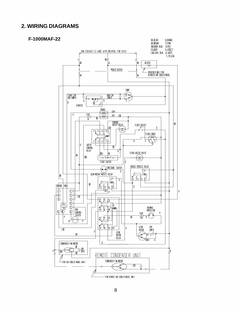
2. WIRING DIAGRAMS
F-1000MAF-22
9
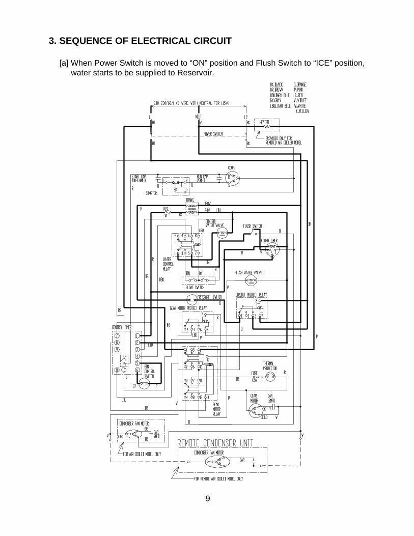
3. SEQUENCE OF ELECTRICAL CIRCUIT
[a] When Power Switch is moved to “ON” position and Flush Switch to “ICE” position, water starts to be supplied to Reservoir.

10
[b] When Reservoir has been filled, Gear Motor starts immediately.

11
[c] Compressor starts about 60 sec. after Gear Motor starts.

12
[d] Bin Control operates, and about 6 sec. later, Compressor and Gear Motor stopsimultaneously.

13
[e] Low Water

14
[f] Dirty Air Filter, Pressure Switch to “OPEN”, Compressor and Gear Motor operatesintermittently.

15
[g] When Flush Switch is moved to “FLUSH” position, Flush Water Valve opens and flushes Reservoir and Evaporator.
16
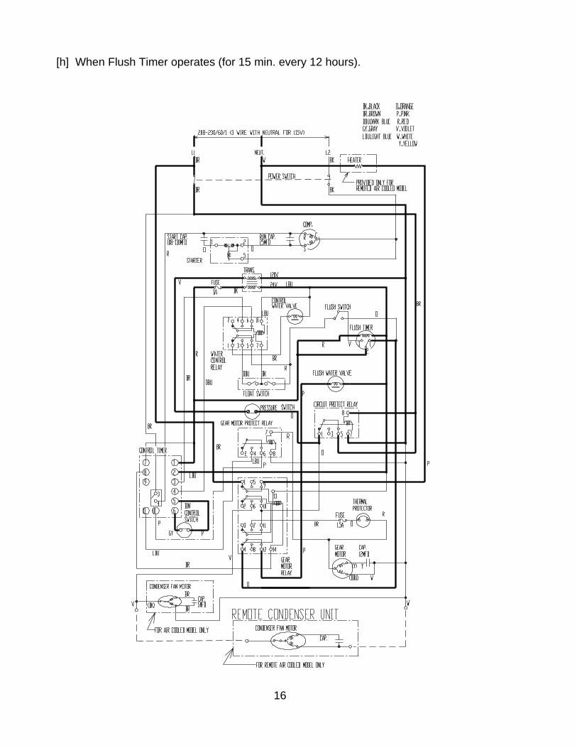
[h] When Flush Timer operates (for 15 min. every 12 hours).
17
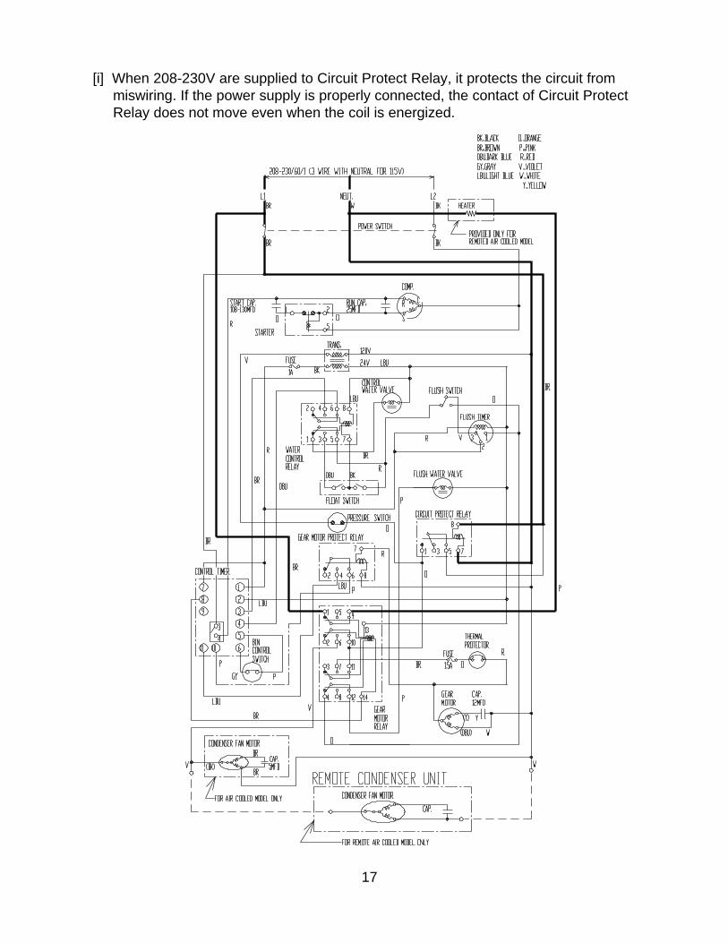
[i] When 208-230V are supplied to Circuit Protect Relay, it protects the circuit from miswiring. If the power supply is properly connected, the contact of Circuit Protect Relay does not move even when the coil is energized.

18
[j] When input voltage is too low, (Less than 70%), Gear Motor Fuse (1.5A) is blown causing the Compressor and Gear Motor to turn off immediately.

19
Miswiring. Circuit Protect Relay operates.)Proper wiring. The unit starts. BIN CONTROL
OFF ON1. CIRCUIT PROTECT
RELAY
2. WATER LEVEL
3. FLOAT
SWITCH
UPPER
LOWER
4. WATER CONTROL
RELAY
5. CONTROL WATER
VALVE
6. FLUSH TIMER
7. FLUSH SWITCH
8. FLUSH WATER
VALVE
9. BIN CONTROL
10. GEAR MOTOR
RELAY
11. GEAR MOTOR
12. FAN MOTOR
13. COMPRESSOR
14. PRESSURE
SWITCH
15. HEATER
ON
OFF
ON
OFF
ON
OFF
ON
OFF
ON
OFF
1 - 2
2 - 3
FLUSH
ICE
ON
OFF
ON
OFF
ON
OFF
ON
OFF
ON
OFF
ON
OFF
ON
OFF
ON
OFF
1 sec
60 sec
6 sec 1 sec
60 sec
UPPER
LOWER
BOTTOM
4. TIMING CHART

20
1. CIRCUIT PROTECT
RELAY
2. WATER LEVEL
3. FLOAT
SWITCH
UPPER
LOWER
4. WATER CONTROL
RELAY
5. CONTROL WATER
VALVE
6. FLUSH TIMER
7. FLUSH SWITCH
8. FLUSH WATER
VALVE
9. BIN CONTROL
10. GEAR MOTOR
RELAY
11. GEAR MOTOR
12. FAN MOTOR
14. PRESSURE
SWITCH
15. HEATER
ON
OFF
ON
OFF
ON
OFF
ON
OFF
ON
OFF
1 - 2
2 - 3
FLUSH
ICE
ON
OFF
ON
OFF
ON
OFF
ON
OFF
ON
OFF
ON
OFF
ON
OFF
ON
OFF
UPPER
LOWERBOTTOM
LOW WATER FLUSH TIMER
21 min every 12 hr
150 sec 1 sec 150 sec
90 sec 60 sec 90 sec 60 sec
1 sec
13. COMPRESSOR

21
1. CIRCUIT PROTECT
RELAY
2. WATER LEVEL
3. FLOAT
SWITCH
UPPER
LOWER
4. WATER CONTROL
RELAY
5. CONTROL WATER
VALVE
6. FLUSH TIMER
7. FLUSH SWITCH
8. FLUSH WATER
VALVE
9. BIN CONTROL
10. GEAR MOTOR
RELAY
11. GEAR MOTOR
12. FAN MOTOR
14. PRESSURE
SWITCH
15. HEATER
ON
OFF
ON
OFF
ON
OFF
ON
OFF
ON
OFF
1 - 2
2 - 3
FLUSH
ICE
ON
OFF
ON
OFF
ON
OFF
ON
OFF
ON
OFF
ON
OFF
ON
OFF
ON
OFF
UPPER
LOWERBOTTOM
FLUSH SWITCH PRESSURE SWITCHFLUSH ICE OFF ON
150 sec 1 sec
90 sec 60 sec
13. COMPRESSOR
1 sec
1 sec
60 sec
22
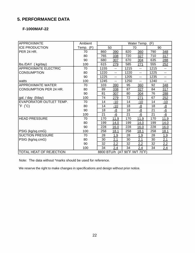
5. PERFORMANCE DATA
F-1000MAF-22
We reserve the right to make changes in specifications and design without prior notice.
APPROXIMATE Ambient Water Temp. (F)ICE PRODUCTION Temp. (F)PER 24 HR. 70 860 390 820 360 790 348
80 765 338 720 327 710 31790 680 307 670 304 635 288
lbs./DAY ( kg/day) 100 615 279 585 271 555 252APPROXIMATE ELECTRIC 70 1155 -- 1215 -- 1215 --CONSUMPTION 80 1220 -- 1220 -- 1225 --
90 1225 -- 1205 -- 1235 --watts 100 1245 -- 1250 -- 1240 --APPROXIMATE WATER 70 103 390 95 360 92 348CONSUMPTION PER 24 HR. 80 89 338 87 327 84 317
90 81 307 80 304 76 288gal. / day (l/day) 100 74 279 72 271 67 252EVAPORATOR OUTLET TEMP. 70 14 -10 14 -10 14 -10˚F (˚C) 80 14 -10 18 -8 18 -8
90 18 -8 18 -8 21 -6100 21 -6 21 -6 21 -6
HEAD PRESSURE 70 170 11.9 170 11.9 170 11.980 199 14.0 199 14.0 199 14.090 228 16.0 228 16.0 228 16.0
PSIG (kg/sq.cmG) 100 258 18.1 258 18.1 258 18.1SUCTION PRESSURE 70 28 1.9 28 1.9 28 1.9PSIG (kg/sq.cmG) 80 30 2.1 30 2.1 30 2.1
90 32 2.2 32 2.2 32 2.2100 34 2.4 34 2.4 34 2.4
TOTAL HEAT OF REJECTION 8800 BTU/h (AT 90˚F /WT 70˚F)
Note: The data without *marks should be used for reference.
50 70 90

23
IV. SERVICE DIAGNOSIS
1. NO ICE PRODUCTION
PROBLEM POSSIBLE CAUSE REMEDY[1] The icemaker will
not start.a) Power Supply 1. OFF position. 1. Move to ON position.
2. Loose connection. 2. Tighten.3. Bad contacts. 3. Check for continuity
and replace.4. Blown fuse. 4. Replace.
b) Power Switch(Control Box)
1. Off position. 1. Move to ON position.2. Bad contacts. 2. Check for continuity
and replace.c) Fuse (Control Box) 1. Blown out. 1. Check for short circuit
and replace.d) Circuit Protect Relay 1. Miswiring. 1. Check power supply
voltage and wireproperly.
e) Flush Timer 1. Flushing out. 1. Wait for 15 minutes.2. Bad contacts. 2. Check for continuity
and replace.f) Flush Switch 1. FLUSH position. 1. Move to ICE position.
2. Bad contacts. 2. Check for continuityand replace.
g) Transformer 1. Coil winding opened. 1. Replace.h) Control Water Valve 1. Coil winding opened. 1. Replace.i) Shut-off Valve 1. Closed. 1. Open.
2. Water failure. 2. Wait till water issupplied.
j) Plug and Receptacle(Control Box)
1. Disconnected. 1. Connect.2. Terminal out of Plug
or Receptacle.2. Insert Terminal back in
position[2] Water flow does not
stop, and theicemaker will notstart
a) Water Control Relay 1. Contact fused. 1. Replace.2. Coil winding opened. 2. Replace.
b) Float Switch 1. Bad contacts. 1. Check for continuityand replace.
2. Float does not movefreely.
2. Clean or replace.
c) Flush Water Valve 1. Valve seat cloggedand water leaking.
1. Clean or replace
d) Hoses 1. Disconnected. 1. Connect.[3] Water has been
supplied, but theicemaker will notstart.
a) Water Control Relay 1. Bad contacts. 1. Check for continuityand replace.
b) Bin Control 1. Bad contacts. 1. Check for continuityand replace.
2. Activator does notmove freely.
2. Clean Axle and itscorresponding holesor replace Bin Control.
c) Gear Motor Relay 1. Coil winding opened. 1. Replace.2. bad contacts. 2. Check for continuity
and replace.d) Control Timer
(Printed CircuitBoard)
1. Broken. 1. Replace.
e) Gear Motor ProtectRelay
1. Coil winding opened. 1. Replace.2. Bad contacts. 2. Check for continuity
and replace.

24
PROBLEM POSSIBLE CAUSE REMEDY
[4] Water has beensupplied, Fan Motorstarts, but GearMotor andCompressor will notstart.
a) Gear Motor Fuse(BUSSMAN GMD1.5A)
1. Blown Fuse. 1.-00
See "3. [3]." Find outthe cause andreplace the Fuse.
b) Thermal Protector(Gear Motor)
1. Bad contacts. 1. Check for continuityand replace.
[5] Gear Motor andCompressor startbut operateintermittently.
a) Pressure Switch 1. Dirty Air Filter orCondenser.
1. Clean.
2. Ambient orcondenser watertemperature toowarm.
2. Get cooler.
3. Fan not rotating. 3. See "3. [1] a) FanMotor."
4. Refrigerantovercharged.
4. Recharge.
5. Refrigerant line orcomponentsplugged.
5. Clean and replacedrier.
6. Bad contacts. 6. Check for continuityand replace.
7. Loose connections. 7. Tighten.[6] Gear Motor starts,
but Compressor willnot start oroperatesintermittently.
a) X2 Relay onControl Timer
1. Bad contacts. 1. Replace.Check forcontinuity andreplace.
2. Coil windingopened.
2. Replace Timer.
b) Starter 1. Bad contacts. 1. Check for continuityand replace.
2. Coil windingopened.
2. Replace.
3. Loose Connections. 3. Tighten.c) Start Capacitor or
Run Capacitor1. Defective. 1. Replace.
d) Compressor 1. Loose connections. 1. Tighten.
2. Motor windingopened orgrounded.
2. Replace.
3. Motor Protectortripped.
3. Find out the cause ofoverheat orovercurrent.
e) Power Supply 1. Circuit Ampacitytoo low.
1. Install a larger-sizedconductor.
[7] Gear Motor andCompressor start,but no ice isproduced.
a) Refrigerant Line 1. Gas leaks. 1. Check for leaks witha leak detector.Reweld leak, replacedrier and charge withrefrigerant. Theamount of refrigerantis marked onNameplate or Label.
2. Refrigerant lineclogged.
2. Replace the cloggedcomponent.
25
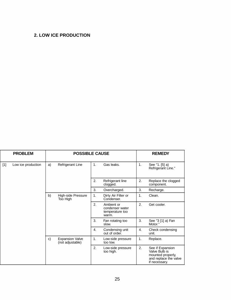
2. LOW ICE PRODUCTION
PROBLEM POSSIBLE CAUSE REMEDY
[1] Low ice production a) Refrigerant Line 1. Gas leaks. 1. See "1. [5] a)Refrigerant Line."
2. Refrigerant lineclogged.
2. Replace the cloggedcomponent.
3. Overcharged. 3. Recharge.b) High-side Pressure
Too High1. Dirty Air Filter or
Condenser.1. Clean.
2. Ambient orcondenser watertemperature toowarm.
2. Get cooler.
3. Fan rotating tooslow.
3. See "3 [1] a) FanMotor."
4. Condensing unitout of order.
4. Check condensingunit.
c) Expansion Valve(not adjustable)
1. Low-side pressuretoo low.
1. Replace.
2. Low-side pressuretoo high.
2. See if ExpansionValve Bulb ismounted properly,and replace the valveif necessary.

26
3. OTHERS

27
V. REMOVAL AND REPLACEMENT OF COMPONENTS
IMPORTANT
Ensure all components, fasteners and thumbscrews are securely in placeafter the equipment is serviced.
1. SERVICE FOR REFRIGERANT LINES
[a] REFRIGERANT RECOVERY
The icemaker unit is provided with two Refrigerant Access Valves - one on the low-side andone on the high-side line. Using proper refrigerant practices recover the refrigerant from theAccess Valves and store it in an approved container. Do not discharge the refrigerant intothe atmosphere.
[b] EVACUATION AND RECHARGE [R-22]
1) Attach Charging Hoses, a Service Manifold and a Vacuum Pump to the system. Besure to connect Charging Hoses to both High-side and Low-side Access Valves.
2) Turn on the Vacuum Pump. Never allow the oil in the Vacuum Pump to flow backward.
3) Allow the Vacuum Pump to pull down to a 29.9" Hg vacuum. Evacuating period de-pends on pump capacity.
4) Close the Low-side Valve and High-side Valve on the Service Manifold.
5) Disconnect the Vacuum Pump, and attach a Refrigerant Service Cylinder to the High-side line. Remember to loosen the connection, and purge the air from the Hose. Seethe Nameplate for the required refrigerant charge. Hoshizaki recommends only virginrefrigerant or reclaimed refrigerant which meets ARI Standard No. 700-88 be used.
6) Open the Low-side Valve. Do not invert the Service Cylinder. A liquid charge willdamage the Compressor.
7) Turn on the icemaker when charging speed gets slow. Turn off the icemaker when theLow-side Gauge shows approximately 0 PSIG. Do not run the icemaker at negativepressures. Close the Low-side Valve when the Service Cylinder gets empty.
8) Repeat the above steps 4) through 7), if necessary, until the required amount ofrefrigeratant has entered the system.
28
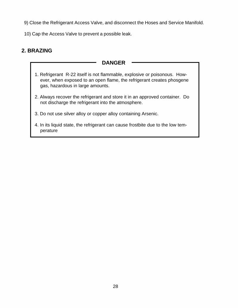
2. BRAZING
DANGER
1. Refrigerant R-22 itself is not flammable, explosive or poisonous. How-ever, when exposed to an open flame, the refrigerant creates phosgenegas, hazardous in large amounts.
2. Always recover the refrigerant and store it in an approved container. Donot discharge the refrigerant into the atmosphere.
3. Do not use silver alloy or copper alloy containing Arsenic.
4. In its liquid state, the refrigerant can cause frostbite due to the low tem-perature
9) Close the Refrigerant Access Valve, and disconnect the Hoses and Service Manifold.
10) Cap the Access Valve to prevent a possible leak.

29
3. REMOVAL AND REPLACEMENT OF COMPRESSOR
IMPORTANT
Always install a new Drier every time the sealed refrigeration system isopened. Do not replace the Drier until after all other repairs or replacementhave been made.
1) Turn off the power supply, and remove the panels.
2) Remove the Terminal Cover on the Compressor, and disconnect the CompressorWiring.
3) Recover the refrigerant and store it in an approved container, if required by an applicablelaw.
4) Remove the Discharge, Suction and Access Pipes from the Compressor using brazingequipment.
WARNING
When repairing a refrigerant system, be careful not to let the burner flamecontact any electrical wires or insulation.
5) Remove the Bolts and Rubber Grommets.
6) Slide and remove the Compressor. Unpack the new Compressor package. Install thenew Compressor.
7) Attach the Rubber Grommets of the prior Compressor.
8) Sandpaper the Discharge, Suction and Access Pipes.
9) Place the Compressor in position, and secure it using the Bolts.
10) Remove plugs from the Discharge, Suction and Access Pipes.
11) Braze the Access, Suction and Discharge lines (Do not change this order), while purgingwith nitrogen gas flowing at the pressure of 3-4 PSIG.
12) Install the new Drier.
13) Check for leaks using nitrogen gas (140 PSIG) and soap bubbles.
30
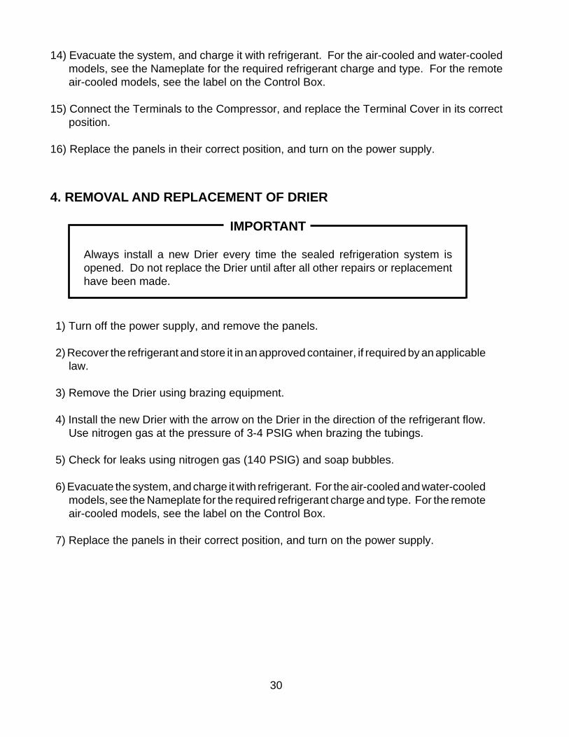
14) Evacuate the system, and charge it with refrigerant. For the air-cooled and water-cooledmodels, see the Nameplate for the required refrigerant charge and type. For the remoteair-cooled models, see the label on the Control Box.
15) Connect the Terminals to the Compressor, and replace the Terminal Cover in its correctposition.
16) Replace the panels in their correct position, and turn on the power supply.
4. REMOVAL AND REPLACEMENT OF DRIER
IMPORTANT
Always install a new Drier every time the sealed refrigeration system isopened. Do not replace the Drier until after all other repairs or replacementhave been made.
1) Turn off the power supply, and remove the panels.
2) Recover the refrigerant and store it in an approved container, if required by an applicablelaw.
3) Remove the Drier using brazing equipment.
4) Install the new Drier with the arrow on the Drier in the direction of the refrigerant flow.Use nitrogen gas at the pressure of 3-4 PSIG when brazing the tubings.
5) Check for leaks using nitrogen gas (140 PSIG) and soap bubbles.
6) Evacuate the system, and charge it with refrigerant. For the air-cooled and water-cooledmodels, see the Nameplate for the required refrigerant charge and type. For the remoteair-cooled models, see the label on the Control Box.
7) Replace the panels in their correct position, and turn on the power supply.

31
5. REMOVAL AND REPLACEMENT OF EXPANSION VALVE
IMPORTANT
Sometimes moisture in the refrigerant circuit exceeds the Drier capacity andfreezes up at the Expansion Valve. Always install a new Drier every time thesealed refrigeration system is opened. Do not replace the Drier until after allother repairs or replacement have been made.
1) Turn off the power supply, and remove the panels.
2) Recover the refrigerant and store it in an approved container, if required by an applicablelaw.
3) Remove the Expansion Valve Bulb at the Evaporator outlet.
4) Remove the Expansion Valve Cover, and remove the Expansion Valve using brazingequipment.
5) Braze the new Expansion Valve with nitrogen gas flowing at the pressure of 3-4 PSIG.
WARNING
Always protect the valve body by using a damp cloth to prevent the valve fromoverheating. Do not braze with the valve body exceeding 250°F.
6) Install the new Drier.
7) Check for leaks using nitrogen gas (140 PSIG) and soap bubbles.
8) Evacuate the system. Charge it with refrigerant. For the air-cooled and water-cooledmodels, see the Nameplate for the required refrigerant charge and type. For the remoteair-cooled models, see the label on the Control Box.
9) Attach the Bulb to the suction line. Be sure to secure the Bulb using a band and toinsulate it.
10) Place the new set of Expansion Valve Covers in position.
11) Replace the panels in their correct position, and turn on the power supply.
32
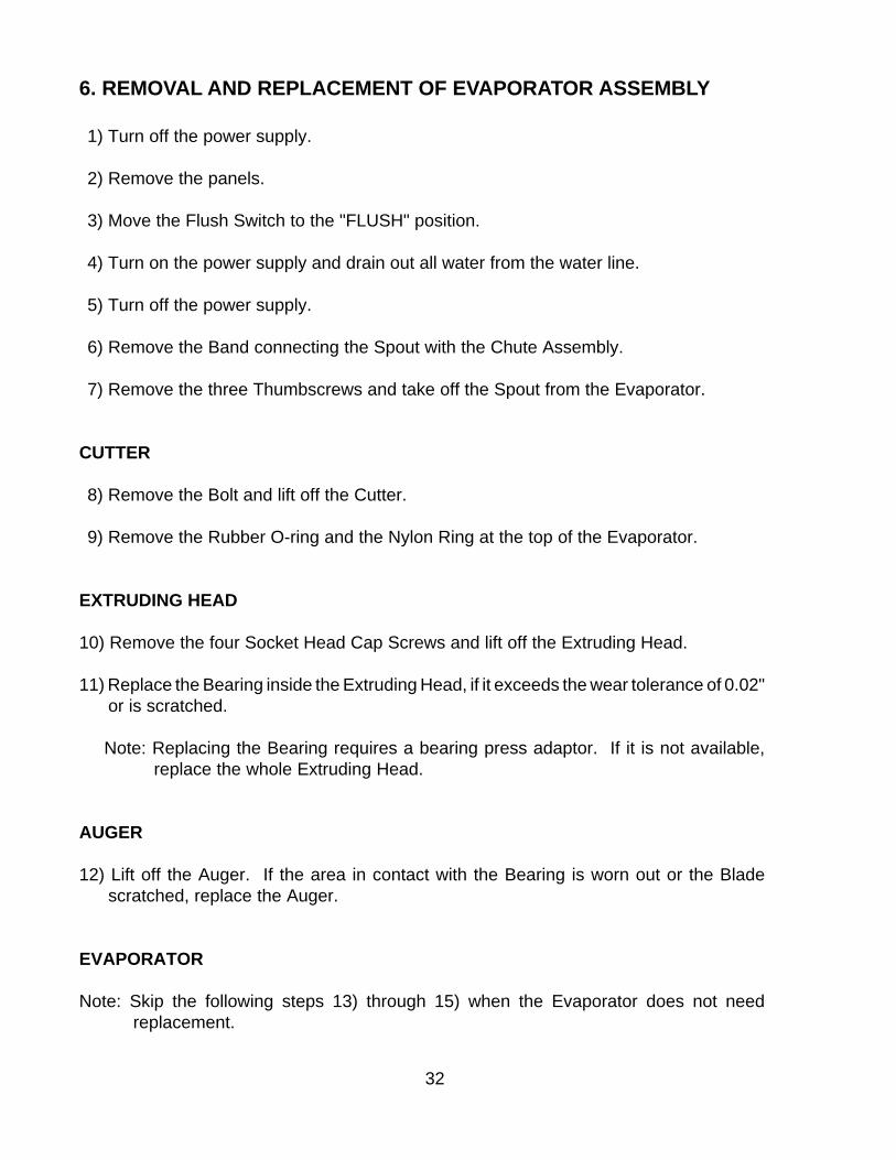
6. REMOVAL AND REPLACEMENT OF EVAPORATOR ASSEMBLY
1) Turn off the power supply.
2) Remove the panels.
3) Move the Flush Switch to the "FLUSH" position.
4) Turn on the power supply and drain out all water from the water line.
5) Turn off the power supply.
6) Remove the Band connecting the Spout with the Chute Assembly.
7) Remove the three Thumbscrews and take off the Spout from the Evaporator.
CUTTER
8) Remove the Bolt and lift off the Cutter.
9) Remove the Rubber O-ring and the Nylon Ring at the top of the Evaporator.
EXTRUDING HEAD
10) Remove the four Socket Head Cap Screws and lift off the Extruding Head.
11) Replace the Bearing inside the Extruding Head, if it exceeds the wear tolerance of 0.02"or is scratched.
Note: Replacing the Bearing requires a bearing press adaptor. If it is not available,replace the whole Extruding Head.
AUGER
12) Lift off the Auger. If the area in contact with the Bearing is worn out or the Bladescratched, replace the Auger.
EVAPORATOR
Note: Skip the following steps 13) through 15) when the Evaporator does not needreplacement.
33
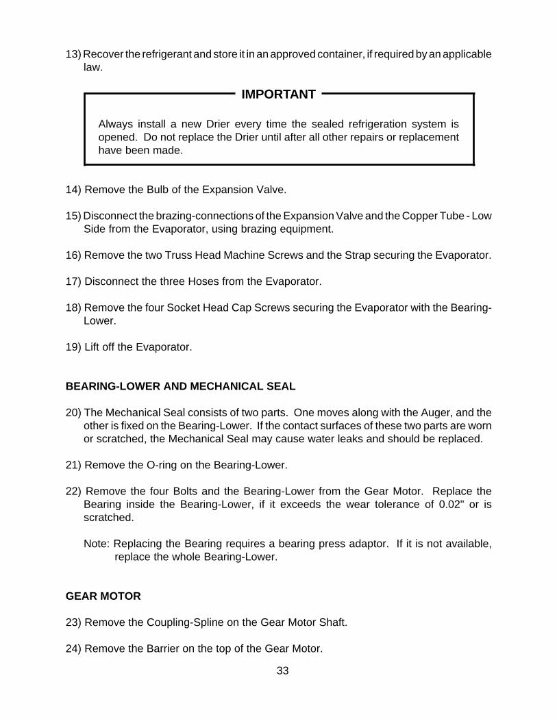
13) Recover the refrigerant and store it in an approved container, if required by an applicablelaw.
IMPORTANT
Always install a new Drier every time the sealed refrigeration system isopened. Do not replace the Drier until after all other repairs or replacementhave been made.
14) Remove the Bulb of the Expansion Valve.
15) Disconnect the brazing-connections of the Expansion Valve and the Copper Tube - LowSide from the Evaporator, using brazing equipment.
16) Remove the two Truss Head Machine Screws and the Strap securing the Evaporator.
17) Disconnect the three Hoses from the Evaporator.
18) Remove the four Socket Head Cap Screws securing the Evaporator with the Bearing-Lower.
19) Lift off the Evaporator.
BEARING-LOWER AND MECHANICAL SEAL
20) The Mechanical Seal consists of two parts. One moves along with the Auger, and theother is fixed on the Bearing-Lower. If the contact surfaces of these two parts are wornor scratched, the Mechanical Seal may cause water leaks and should be replaced.
21) Remove the O-ring on the Bearing-Lower.
22) Remove the four Bolts and the Bearing-Lower from the Gear Motor. Replace theBearing inside the Bearing-Lower, if it exceeds the wear tolerance of 0.02" or isscratched.
Note: Replacing the Bearing requires a bearing press adaptor. If it is not available,replace the whole Bearing-Lower.
GEAR MOTOR
23) Remove the Coupling-Spline on the Gear Motor Shaft.
24) Remove the Barrier on the top of the Gear Motor.
34
25) Remove the three Socket Head Cap Screws securing the Gear Motor.
26) Assemble the removed parts in the reverse order of the above procedure.
WARNING
Be careful not to scratch the surface of the O-ring, or it may cause water leaks.Handle the Mechanical Seal with care not to scratch nor to contaminate itscontact surface.
27) When replacing the Evaporator;
(a) Braze the new Evaporator with nitrogen gas flowing at the pressure of 3-4 PSIG.
(b) Replace the Drier.
(c) Check for leaks using nitrogen gas (140 PSIG) and soap bubbles.
(d) Evacuate the system. Charge it with refrigerant. For the air-cooled and water-cooled models, see the Nameplate for required refrigerant charge and type. Forthe remote air-cooled models, see the label on the Control Box.
28) Move the Flush Switch to the “ICE” position.
29) Replace the panels in their correct position.
30) Turn on the power supply.
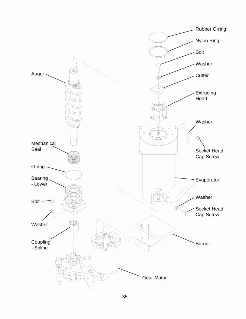
35
Auger
MechanicalSeal
O-ring
Bearing- Lower
Bolt
Washer
Coupling- Spline
Rubber O-ring
Nylon Ring
Bolt
Washer
Cutter
ExtrudingHead
Washer
Socket HeadCap Screw
Evaporator
Washer
Socket HeadCap Screw
Barrier
Gear Motor
36
7. REMOVAL AND REPLACEMENT OF FAN MOTOR
1) Turn off the power supply and remove the panels.
2) Remove the wire connectors from the Fan Motor leads.
3) Remove the Fan Motor Bracket and Fan Motor.
4) Install the new Fan Motor.
5) Replace the Fan Motor Bracket and the wire connectors.
6) Replace the panels in their correct position, and turn on the power supply.
8. REMOVAL AND REPLACEMENT OF CONTROL WATER VALVE
1) Turn off the power supply, remove the panels and close the Water Supply Line Shut-off Valve.
2) Disconnect the Terminals from the Control Water Valve.
3) Loosen the Fitting Nut on the Control Water Valve Inlets, and remove the Control WaterValve. Do not lose the Packings inside the Fitting Nut.
4) Remove the Water Supply Hose from the Control Water Valve.
5) Install the new Control Water Valve.
6) Assemble the removed parts in the reverse order of the above procedure.
7) Open the Water Supply Line Shut-off Valve.
8) Check for water leaks.
9) Replace the panels in their correct position, and turn on the power supply.
37
9. REMOVAL AND REPLACEMENT OF FLUSH WATER VALVE
1) Turn off the power supply, remove the panels and close the Water Supply Line Shut-off Valve.
2) Remove the Clamp and disconnect the Hose from the Flush Water Valve.
Note: Water may still remain inside the Evaporator. Be sure to drain the water into theDrain Pan.
3) Disconnect the Terminals from the Flush Water Valve.
4) Remove the Flush Water Valve from the Bracket.
5) Remove the Drain Pipe from the Flush Water Valve.
6) Connect the Drain Pipe to the new Flush Water Valve, and place the valve in position.
7) Connect the Hose to the Flush Water Valve and secure it with the Clamp.
8) Pour water into the Reservoir, and check for water leaks on the Flush Water Valve.
9) Open the Water Supply Line Shut-off Valve, and turn on the power supply.
10) Move the Flush Switch to the “ICE” position.
11) Check for water leaks.
12) Move the Flush Switch to the “FLUSH” position, and make sure water is flushing.
13) Move the Flush Switch to the “ICE” position.
14) Replace the panels in their correct position.

38
VI. MAINTENANCE AND CLEANING INSTRUCTIONS
IMPORTANT
Ensure all components, fasteners and thumbscrews are securely in placeafter any maintenance or cleaning is done to the equipment.
1. PREPARING THE ICEMAKER FOR LONG STORAGE
WARNING
When shutting off the icemaker for an extended time, drain out all water fromthe water line and remove the ice from the Storage Bin. The Storage Binshould be cleaned and dried. Drain the icemaker to prevent damage to thewater supply line at sub-freezing temperatures, using air or carbon dioxide.Shut off the icemaker until the proper ambient temperature is resumed.
1) Run the icemaker with the Water Supply Line Shut-off Valve closed.
2) Open the Drain Valve and blow out the water inlet line by using air pressure.
3) Turn off the power supply.
4) Remove the Front Panel.
5) Move the Flush Switch on the Control Box to the“FLUSH” position.
6) Turn on the power supply, and then drain out allwater from the water line.
7) Turn off the power supply.
8) Turn off the Power Switch on the Control Box.
9) Replace the Front Panel in its correct position.
10) Close the Drain Valve.
11) Remove all ice from the Storage Bin, and clean the bin.

39
2. CLEANING INSTRUCTIONS
WARNING
1. HOSHIZAKI recommends cleaning this unit at least once a year. Morefrequent cleaning, however, may be required in some existing waterconditions.
2. To prevent injury to individuals and damage to the icemaker, do not useammonia type cleaners.
3. Always wear liquid-proof gloves for safe handling of the cleaning andsanitizing solution. This will prevent irritation in case the solution comesinto contact with skin.
<STEP 1>
Dilute the solutions with water as follows.
Cleaning solution: 4.8 fl. oz. of recommended cleaner Hoshizaki “Scale Away” or“LIME-A-WAY” (Economics Laboratory, Inc.) with 0.8 gal. of water.This is a minimum amount. Make more solution, if necessary.
Sanitizing solution: 2.5 fl. oz. of a 5.25% sodium hypochlorite solution (chlorine bleach)with 5 gal. of water.
IMPORTANT
For safety and maximum effectiveness, use the solution immediately afterdilution.
<STEP 2>
Use the cleaning solution to remove lime deposits in the water system.
1) Turn off the power supply.
2) Close the Water Supply Line Shut-off Valve.
3) Remove all ice from the Storage Bin.
4) Remove the Front Panel and the Top Panel.
5) Move the Flush Switch to the “FLUSH” position.

40
6) Turn on the power supply and drain out all water from the water line.
7) Turn off the power supply.
8) Remove the Control Water Valve by releasing the Fitting Nut. Do not lose the Packing.
9) Remove the Cover of the Reservoir.
10) Fill the Reservoir with the cleaning solution.
11) Replace the Cover of the Reservoir and the Control Water Valve in their correct position.
Note: This unit is designed to start operating when the Reservoir is filled with water.
12) Move the Flush Switch to the “ICE” position.
13) Replace the Top Panel and the Front Panel in their correct position.
14) Allow the icemaker to set for about 10 minutes before the operation. Then, turn on thepower supply, and make ice using the solution until the icemaker stops icemaking.
15) Remove the Front Panel.
16) Move the Flush Switch to the “FLUSH” position to drain the cleaning solution.
17) Move the Flush Switch to the “ICE” position.
18) Replace the Front Panel in its correct position.
19) Open the Water Supply Line Shut-off Valve, and supply water to the Reservoir.
20) Turn off the power supply when the Gear Motor starts.
21) Drain out all water from the water line. See 4) through 7).
<STEP 3>
Use 3/4 gal. of the sanitizing solution to sanitize the icemaker.
1) Close the Water Supply Line Shut-off Valve.
2) Remove the Control Water Valve by releasing the Fitting Nut.
3) Remove the Cover of the Reservoir.
4) Fill the Reservoir with the sanitizing solution.

41
5) Replace the Cover of the Reservoir and the Control Water Valve in their correct position.
6) Move the Flush Switch to the “ICE” position.
7) Replace the Top Panel and the Front Panel in their correct position.
8) Allow the icemaker to set for about 10 minutes before the operation. Then, turn on thepower supply, and make ice using the solution until the icemaker stops icemaking.
9) Remove the Front Panel.
10) Move the Flush Switch to the “FLUSH” position to drain the sanitizing solution.
11) Move the Flush Switch to the “ICE” position.
12) Replace the Front Panel in its correct position.
13) Open the Water Supply Line Shut-off Valve, and supply water to the Reservoir.
14) Turn off the power supply when the Gear Motor starts.
15) Drain out all water from the water line. See 4) through 7) in STEP 2.
16) Move the Flush Switch to the “ICE” position.
<STEP 4>
Use the sanitizing solution to sanitize removed parts.
1) Remove the Thumbscrew securing the Bin Control Switch on the Chute Assembly.
2) Remove the Band connecting the Spout with the Chute Assembly, and take out theChute Assembly from the icemaker.
3) Remove the Gasket at the bottom of the Ice Chute and another at the Spout.
4) Remove the three Ties and the Insulation of the Chute.
5) Remove the six Wing Nuts and two Baffles.
IMPORTANT
When installing the Baffles, make sure that the bent surface (the one withoutthe studs) faces the Activator so that the bent surface can guide the ice to thecenter of the Activator.

42
6) Remove the two Thumbscrews, Plate, and Gasket at the top of the Ice Chute, and thenremove the Bin Control Assembly by sliding it slightly toward the Spout and lifting it off.
7) Disassemble the Bin Control Assembly by removing the two Snap Pins, Shaft andActivator.
8) Remove the three Thumbscrews and the Spout.
9) Remove the Rubber O-ring and Nylon Ring at the top of the Cylinder.
10) Soak or wipe the removed parts.
11) Rinse these parts thoroughly.
IMPORTANT
If the solution is left on these parts, they will rust.
12) Replace the removed parts and the panels.
13) Turn on the power supply and run the icemaker.
14) Turn off the power supply after 30 minutes.
15) Pour warm water into the Storage Bin to melt all ice, and then clean the Bin Liner withthe solution.
16) Flush out any solution from the Storage Bin.
17) Turn on the power supply and start the automatic icemaking process.
IMPORTANT
1. After cleaning, do not use ice made from the sanitizing solution. Be carefulnot to leave any solution in the Storage Bin.
2. Follow carefully any instructions provided with the bottles of cleaning orsanitizing solution.
3. Never run the icemaker when the Reservoir is empty.

43
3. MAINTENANCE
IMPORTANT
1. This icemaker must be maintained individually, referring to the instructionmanual and labels provided with the icemaker.
2. To have the optimum performance of this icemaker, the following consumableparts need periodic inspection, maintenance and replacement:
Extruding HeadHousingGear MotorAugerMechanical Seal
These parts should be inspected at least once a year or every 10,000 hoursof operation. Their service life, however, depends on water quality andenvironment. More frequent inspection and maintenance are recommended.
Consult with your local distributor about inspection and maintenanceservice. To obtain the name and phone number of your local distributor, callHoshizaki Technical Support at 1-800-233-1940.
1) Stainless Steel Exterior
To prevent corrosion, wipe the exterior occasionally with a clean and soft cloth. Usea damp cloth containing a neutral cleaner to wipe off oil or dirt build up.
2) Storage Bin and Scoop
• Wash your hands before removing ice. Use the plastic scoop provided (Bin accessory).• The Storage Bin is for ice use only. Do not store anything else in the bin.• Keep the scoop clean. Clean using a neutral cleaner and rinse thoroughly.• Clean the bin liner using a neutral cleaner. Rinse thoroughly after cleaning. Wash your hands before removing ice. Use the plastic scoop provided (Bin accessory).
44
3) Air Filter
A plastic mesh air filter removes dirt or dust from the air, and keeps the Condenserfrom getting clogged. As the filter gets clogged, the icemaker’s performance will bereduced. Check the filter at least twice a month. When clogged, use warm water anda neutral cleaner to wash the filter.
4) Condenser
Check the Condenser once a year, and clean if required by using a brush or vacuumcleaner. More frequent cleaning may be required depending on the location of theicemaker.