Embed Size (px)
Citation preview
ASSEMBLY INSTRUCTIONS
GC0410
HOSE REEL TROLLEYModel No CHC90
Part No 7956025
(Hose notincluded)
2
INTRODUCTION
Thank you for purchasing this CLARKE Hose Reel Trolley.
Before attempting to use this product, it is essential that you read this manualthoroughly and carefully follow all instructions given. In doing so you willensure the safety of yourself and that of others around you, and you can alsolook forward to the product giving you long and satisfactory service.
GUARANTEE
This CLARKE product is guaranteed against faulty manufacture for a period of12 months from the date of purchase. Please keep your receipt as proof ofpurchase.
This guarantee is invalid if the product is found to have been abused ortampered with in any way, or not used for its intended purpose.
Faulty goods should be returned to their place of purchase, no product canbe returned to us without prior permission.
This guarantee does not effect your statutory rights.
ENVIRONMENTAL PROTECTION
Do not dispose of this product with general household waste. Alltools, accessories and packaging should be sorted, taken to arecycling centre and disposed of appropriately.
TECHNICAL SPECIFICATIONS
Please note that the details and specifications contained herein, are correct at thetime of going to print. However, CLARKE International reserve the right to changespecifications at any time without prior notice.
erutaeF noitacificepS
thgieW gk81
)HxDxL(snoisnemiD mm0101x016x039
egarotSesoHxaM )m5.19(tf003
htgneLesoHtelnI mm0081
rotcennoCesoHtelnI rotcennocpatdedaerht"4/3ssarB
seryTcitamuenP )detarisp03xam(ediwmm08xaidmm562
3
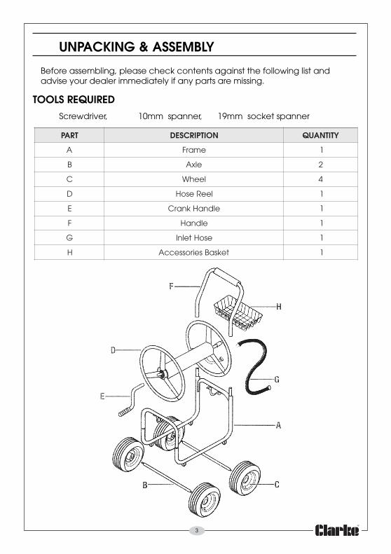
UNPACKING & ASSEMBLY
Before assembling, please check contents against the following list andadvise your dealer immediately if any parts are missing.
TOOLS REQUIREDScrewdriver, 10mm spanner, 19mm socket spanner
TRAP NOITPIRCSED YTITNAUQ
A emarF 1
B elxA 2
C leehW 4
D leeResoH 1
E eldnaHknarC 1
F eldnaH 1
G esoHtelnI 1
H teksaBseirosseccA 1
4
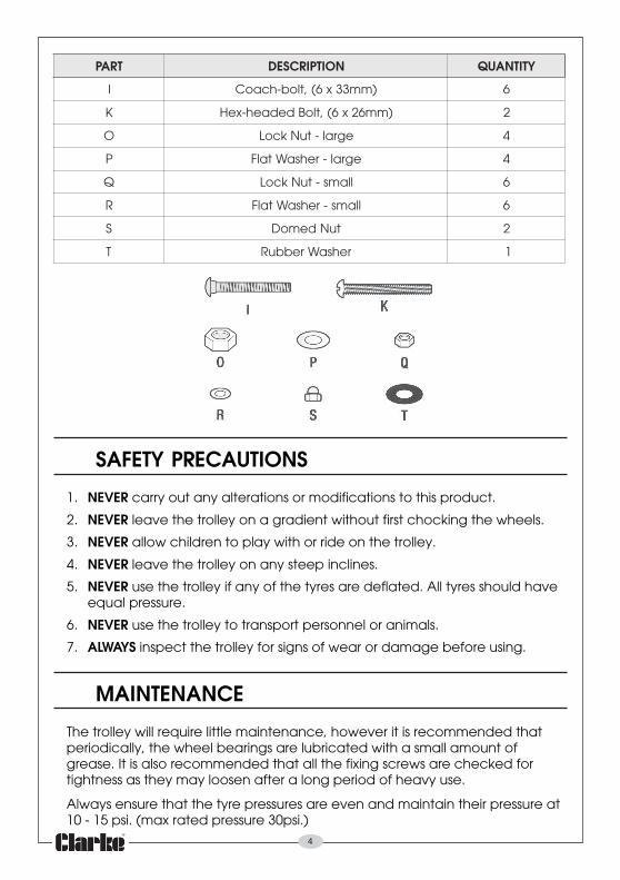
TRAP NOITPIRCSED YTITNAUQ
I )mm33x6(,tlob-hcaoC 6
K )mm62x6(,tloBdedaeh-xeH 2
O egral-tuNkcoL 4
P egral-rehsaWtalF 4
Q llams-tuNkcoL 6
R llams-rehsaWtalF 6
S tuNdemoD 2
T rehsaWrebbuR 1
SAFETY PRECAUTIONS
1. NEVER carry out any alterations or modifications to this product.
2. NEVER leave the trolley on a gradient without first chocking the wheels.
3. NEVER allow children to play with or ride on the trolley.
4. NEVER leave the trolley on any steep inclines.
5. NEVER use the trolley if any of the tyres are deflated. All tyres should haveequal pressure.
6. NEVER use the trolley to transport personnel or animals.
7. ALWAYS inspect the trolley for signs of wear or damage before using.
MAINTENANCE
The trolley will require little maintenance, however it is recommended thatperiodically, the wheel bearings are lubricated with a small amount ofgrease. It is also recommended that all the fixing screws are checked fortightness as they may loosen after a long period of heavy use.
Always ensure that the tyre pressures are even and maintain their pressure at10 - 15 psi. (max rated pressure 30psi.)
5
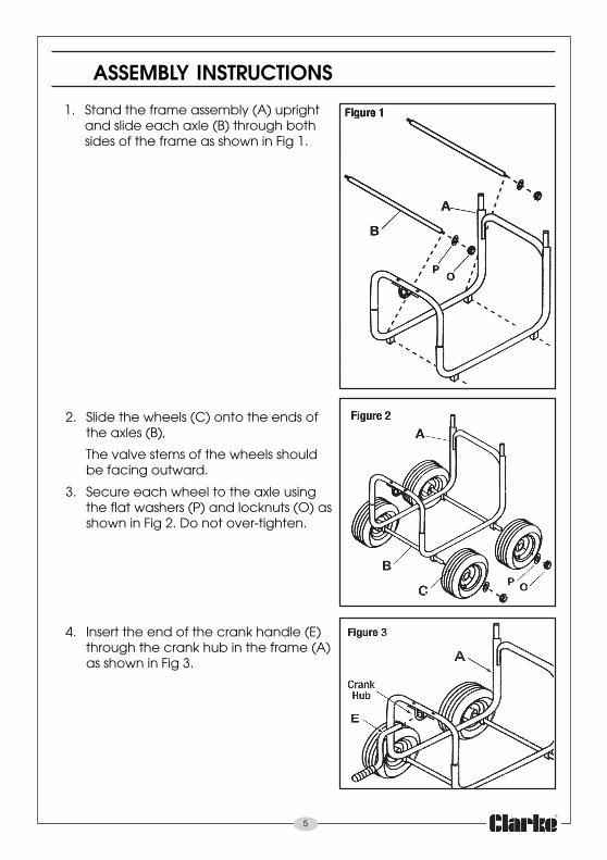
2. Slide the wheels (C) onto the ends ofthe axles (B),
The valve stems of the wheels shouldbe facing outward.
3. Secure each wheel to the axle usingthe flat washers (P) and locknuts (O) asshown in Fig 2. Do not over-tighten.
4. Insert the end of the crank handle (E)through the crank hub in the frame (A)as shown in Fig 3.
ASSEMBLY INSTRUCTIONS
1. Stand the frame assembly (A) uprightand slide each axle (B) through bothsides of the frame as shown in Fig 1.
6
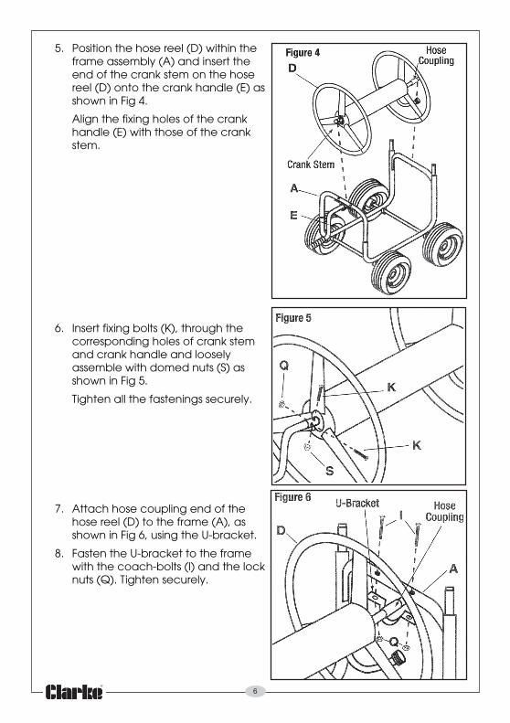
5. Position the hose reel (D) within theframe assembly (A) and insert theend of the crank stem on the hosereel (D) onto the crank handle (E) asshown in Fig 4.
Align the fixing holes of the crankhandle (E) with those of the crankstem.
6. Insert fixing bolts (K), through thecorresponding holes of crank stemand crank handle and looselyassemble with domed nuts (S) asshown in Fig 5.
Tighten all the fastenings securely.
7. Attach hose coupling end of thehose reel (D) to the frame (A), asshown in Fig 6, using the U-bracket.
8. Fasten the U-bracket to the framewith the coach-bolts (I) and the locknuts (Q). Tighten securely.
7
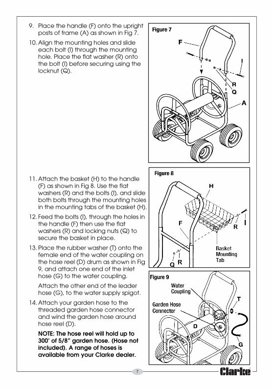
9. Place the handle (F) onto the uprightposts of frame (A) as shown in Fig 7.
10. Align the mounting holes and slideeach bolt (I) through the mountinghole. Place the flat washer (R) ontothe bolt (I) before securing using thelocknut (Q).
11. Attach the basket (H) to the handle(F) as shown in Fig 8. Use the flatwashers (R) and the bolts (I), and slideboth bolts through the mounting holesin the mounting tabs of the basket (H).
12. Feed the bolts (I), through the holes inthe handle (F) then use the flatwashers (R) and locking nuts (Q) tosecure the basket in place.
13. Place the rubber washer (T) onto thefemale end of the water coupling onthe hose reel (D) drum as shown in Fig9, and attach one end of the inlethose (G) to the water coupling.
Attach the other end of the leaderhose (G), to the water supply spigot.
14. Attach your garden hose to thethreaded garden hose connectorand wind the garden hose aroundhose reel (D).
NOTE: The hose reel will hold up to300’ of 5/8” garden hose. (Hose notincluded). A range of hoses isavailable from your Clarke dealer.