Embed Size (px)
Citation preview
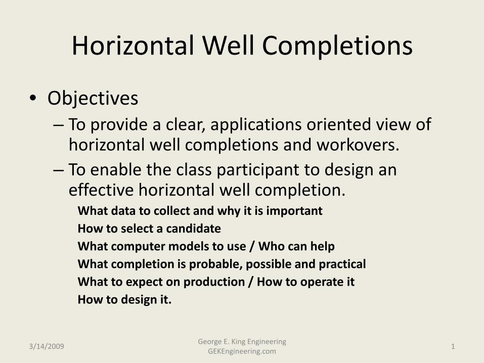
Horizontal Well Completions
• Objectives– To provide a clear, applications oriented view of
horizontal well completions and workovers.– To enable the class participant to design an
effective horizontal well completion.What data to collect and why it is importantHow to select a candidateWhat computer models to use / Who can helpWhat completion is probable, possible and practicalWhat to expect on production / How to operate itHow to design it.
3/14/2009 1George E. King Engineering
GEKEngineering.com
Horizontal Wells
• First conceived in US and USSR in 1930’s
• First serious attempts in 1950’s
• First successful completions in 1970’s
• Caught on world-wide in 1980’s
• Now a standard well configuration
3/14/2009 2George E. King Engineering
GEKEngineering.com
3/14/2009 3George E. King Engineering
GEKEngineering.com
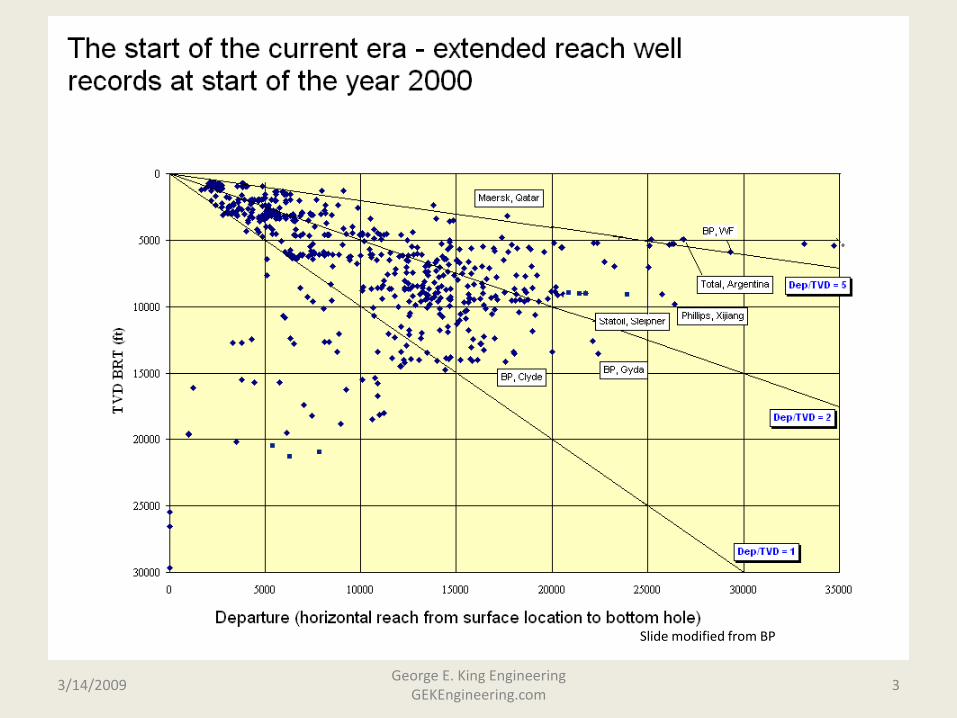
Slide modified from BP
Uses of Horizontal Wells
• increasing reservoir contact
• water/gas coning control
• water/steam injection
• extended reach capability
• minimizing surface locations, slot saving
• improving wellbore location
• prospecting and gathering reservoir info.
• drain individual compartments
3/14/2009 4George E. King Engineering
GEKEngineering.com
Other Uses
• Prospecting - as a tool to prove up seismic in an area
• Accessing all parts of the field - flank wells a favorite in offshore reservoirs
• As a platform for fracturing
• As a “gathering system” - Amoco Canada’s “Big Kahuna”
3/14/2009 5George E. King Engineering
GEKEngineering.com
Favorite Targets
• Naturally fractured chalks and shales
• Water coning problem areas
• Field edges
3/14/2009 6George E. King Engineering
GEKEngineering.com
Best Candidates from a Reservoir Perspective
• 1. Must still have good volume of reserves, pressure and fluids of value.
• 2. Permeability values (horizontal and vertical) more a design consideration than a limit.
• 3. Oil was thought to be a better candidate than gas because of hydraulic fracturing, however, horizontal wells with multistage fracturing are a common completion for low permeability gas plays.
3/14/2009 7George E. King Engineering
GEKEngineering.com

Best - non stimulated candidates
• No vertical barriers and generally high permeability reservoirs.
• Kv/Kh > 0.1 to 0.5 (opinion) (consider frac if perm is too low)
• natural fractures often viewed as “good”, but watch effects on the drainage profile and also bottom water.
3/14/2009 8George E. King Engineering
GEKEngineering.com
Red Flags - for unstimulated horizontals
• Poor quality reservoirs - need something to start with.
• Very low Kv, vertical flow barriers
• Some extremely thick zones
3/14/2009 9George E. King Engineering
GEKEngineering.com
Reservoir Considerations
• Will reduced footprint help? (offshore and high land cost or political areas)
• Will there be improvements in contact with some dipping beds.
• Pay configuration issues:– layers
– boundries
– anisotrophy
3/14/2009 10George E. King Engineering
GEKEngineering.com
Permeability Variance
• Kh, KH, Kv
• Barriers
• Bed angle (a vertical well can be horizontal to the bedding plane in some instances
3/14/2009 11George E. King Engineering
GEKEngineering.com
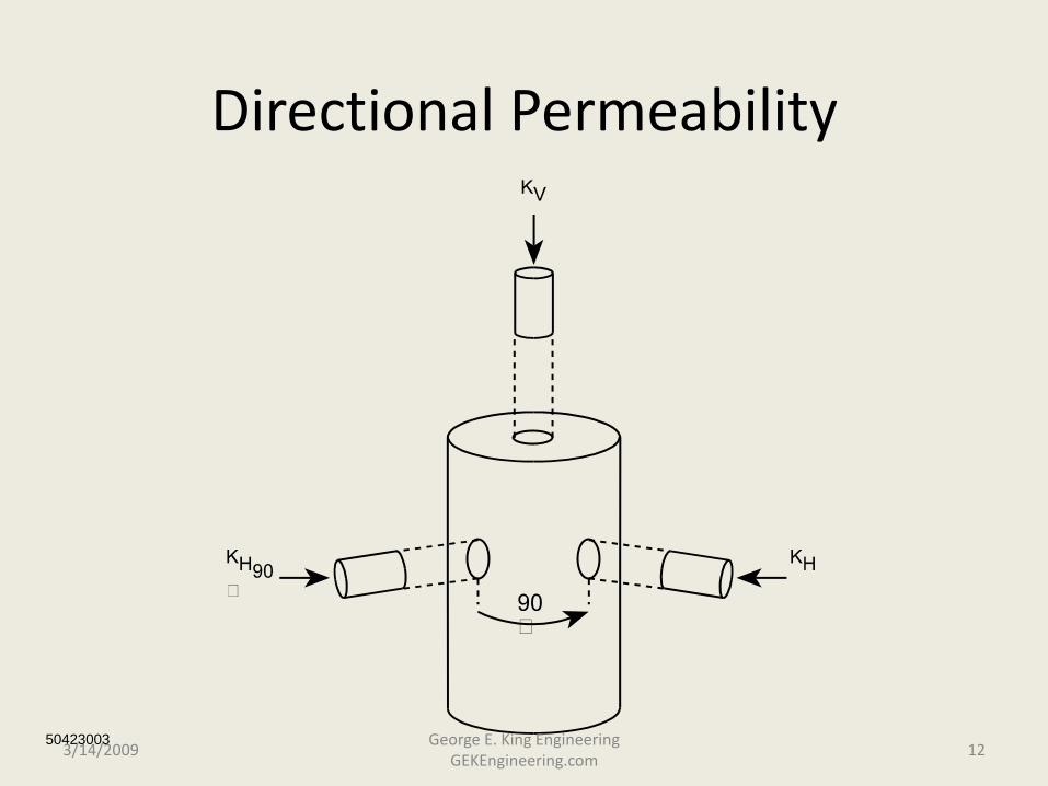
Directional Permeability
504230033/14/2009 12
George E. King Engineering GEKEngineering.com
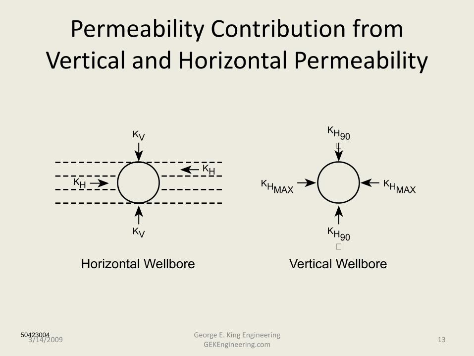
Permeability Contribution from Vertical and Horizontal Permeability
504230043/14/2009 13
George E. King Engineering GEKEngineering.com
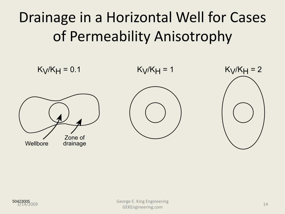
Drainage in a Horizontal Well for Cases of Permeability Anisotrophy
504230053/14/2009 14
George E. King Engineering GEKEngineering.com
Placement of the Horizontal Above the O/W Contact
• Depends on:– vertical permeability
– fluid viscosities
– pay zone thickness
– anomolies in the zone
– depth (?) and formations above the pay zone
3/14/2009 15George E. King Engineering
GEKEngineering.com
Pay Zone Thickness
• no minimum or optimum
• vertical and horizontal permeability more critical– fractures
• incidence of fractures
• location of fractures
• permeability of fractures
• good or bad? - water???
3/14/2009 16George E. King Engineering
GEKEngineering.com

When is a Multi-lateral Required?
• Wherever compartmentalization reduces the ability of a single wellbore (stimulation?) to effectively and economically drain the reservoir.
3/14/2009 17George E. King Engineering
GEKEngineering.com
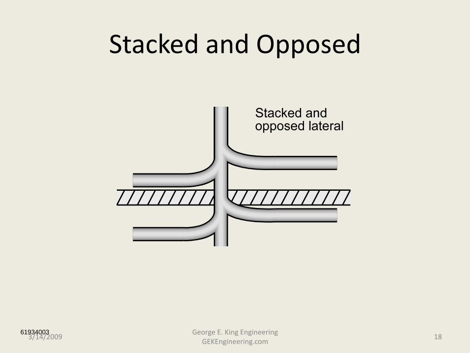
Stacked and Opposed
619340033/14/2009 18
George E. King Engineering GEKEngineering.com
Compartment Recognition
• Geological clues
• DST’s
• Production behavior
• Hydrocarbon source variances (oil fingerprinting)
• Early Recognition - addressed in design
• Later Recognition - requires a workover
3/14/2009 19George E. King Engineering
GEKEngineering.com
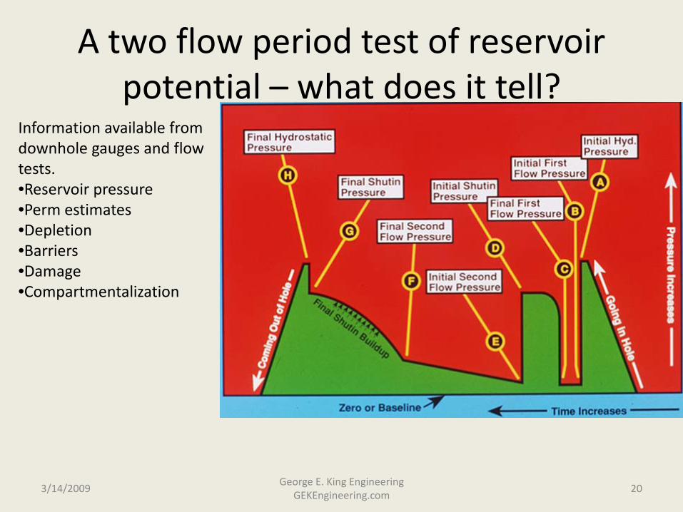
A two flow period test of reservoir potential – what does it tell?
3/14/2009George E. King Engineering
GEKEngineering.com20
Information available from downhole gauges and flow tests. •Reservoir pressure•Perm estimates•Depletion•Barriers•Damage•Compartmentalization
3/14/2009 21George E. King Engineering
GEKEngineering.com
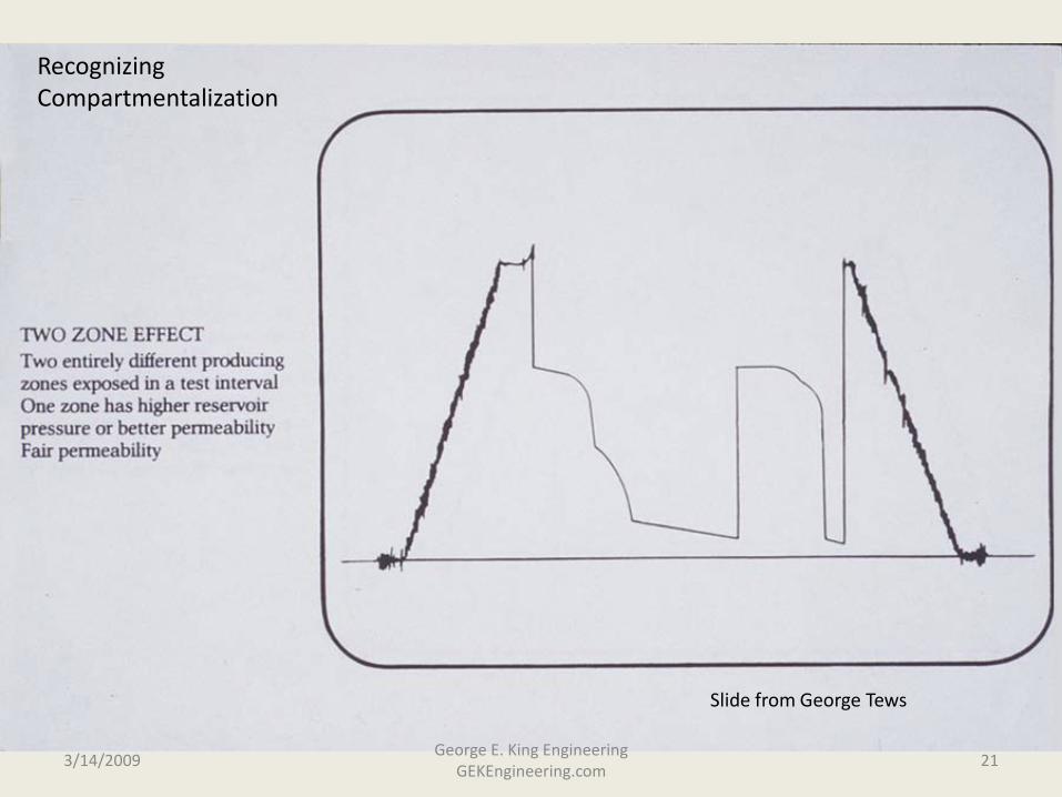
Recognizing Compartmentalization
Slide from George Tews
Horizontal Well Expectations
• Uncertainty???– can it be drilled?
– can it be completed?
– can it be operated/produced?
– is it really a good candidate?
– is fracturing needed?
3/14/2009 22George E. King Engineering
GEKEngineering.com

Horizontal and Lateral Drilling
• An introduction to horizontal well drilling technology: – Goal is to make the engineer/foreman aware of
some problems and solutions available in drilling operations that can have a major effect on completions and production.
3/14/2009 23George E. King Engineering
GEKEngineering.com
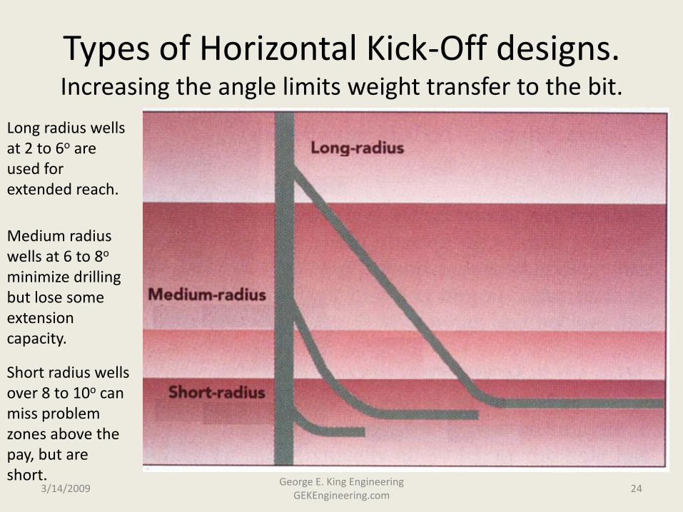
Types of Horizontal Kick-Off designs. Increasing the angle limits weight transfer to the bit.
3/14/2009George E. King Engineering
GEKEngineering.com24
Long radius wells at 2 to 6o are used for extended reach.
Medium radius wells at 6 to 8o
minimize drilling but lose some extension capacity.
Short radius wells over 8 to 10o can miss problem zones above the pay, but are short.
Ability to Lift Cuttings
• Must reach high enough velocities to carry particles upward.– Problems in horizontals:
• limited circulation rate
• large annular areas = low flow velocity
• striated flow regimes – especially at 30o to 60o
• difficult in all liquid systems (rate)
• difficult in all gas systems (striation)
3/14/2009 25George E. King Engineering
GEKEngineering.com
Cuttings Beds
• Symmetric suspension - constant concentration in cross section
• Asymmetric suspension - all carried, but more at bottom
• Moving bed - like a dune• Stationary bed - builds to height dictated by flow rate• Boycott settling - explains severe solids drop out in
the 30 to 60 degree range.
3/14/2009 26George E. King Engineering
GEKEngineering.com
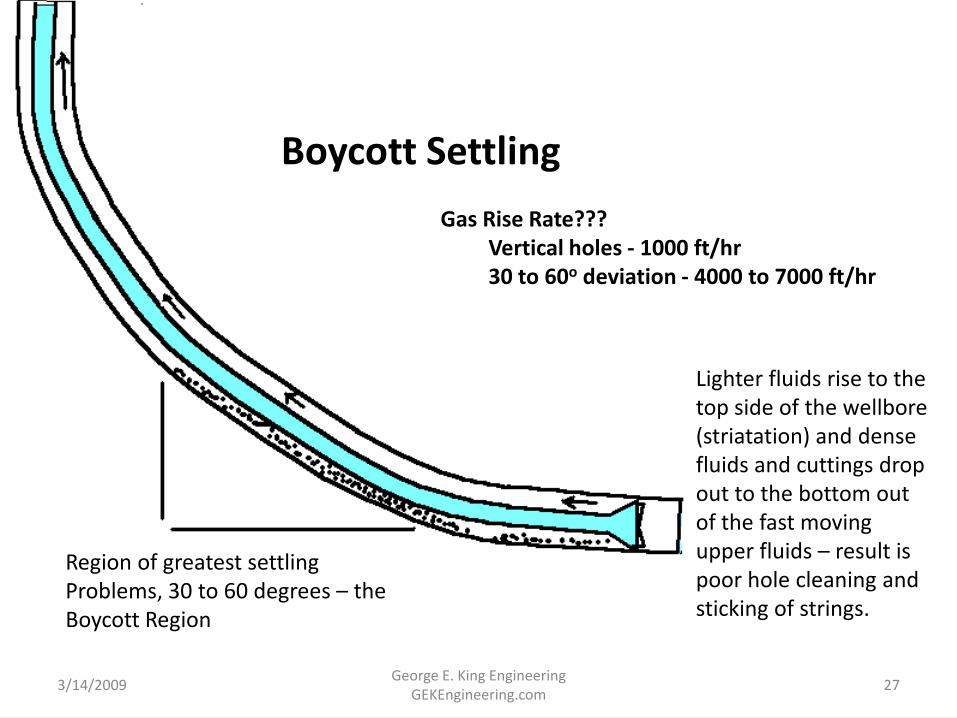
Boycott Settling
Gas Rise Rate???Vertical holes - 1000 ft/hr30 to 60o deviation - 4000 to 7000 ft/hr
Region of greatest settling Problems, 30 to 60 degrees – the Boycott Region
3/14/2009 27George E. King Engineering
GEKEngineering.com
Lighter fluids rise to the top side of the wellbore (striatation) and dense fluids and cuttings drop out to the bottom out of the fast moving upper fluids – result is poor hole cleaning and sticking of strings.
Consequences of Poor Hole Cleaning
• Bridging - sticking pipe
• Failure to run to bottom
• Debris in perfs
• Emulsions and scale “seeds” left in the well?
• Cave-ins? - probably not
3/14/2009 28George E. King Engineering
GEKEngineering.com
3/14/2009 29George E. King Engineering
GEKEngineering.com
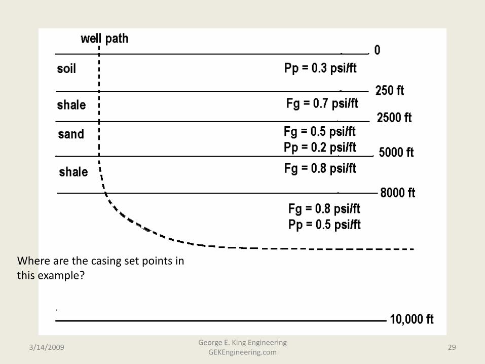
Where are the casing set points in this example?

BUT, is it stable as the hole approaches horizontal? Remember that hole stability is lowest in the bend area.
3/14/2009 30George E. King Engineering
GEKEngineering.com
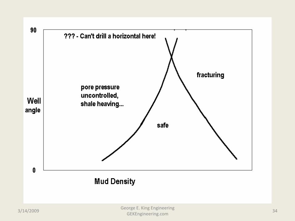
Drilling Fluid Operating “Window”
• Mud density must be higher than the pore pressure to keep fluids from entering the well.
• Mud density must control tendency of shale to spall particles into wellbore
• Mud density must be less than the formation fracture (extension) gradient – corrected for friction pressures while circulating. The pressure exerted by the fluid at any depth is a function of its density plus the friction pressure in the circulating path back to the surface.
3/14/2009 31George E. King Engineering
GEKEngineering.com
Drilling Wellbore Stability
• Issues - during drilling, completion and production
• Destabilizing Mechanism– support pressure too low (spalling)
– support pressure too high (fracturing)
– Rx with drilling fluids (sloughing, swelling)
– formation stress unloading
3/14/2009 32George E. King Engineering
GEKEngineering.com
3/14/2009 33George E. King Engineering
GEKEngineering.com
3/14/2009 34George E. King Engineering
GEKEngineering.com
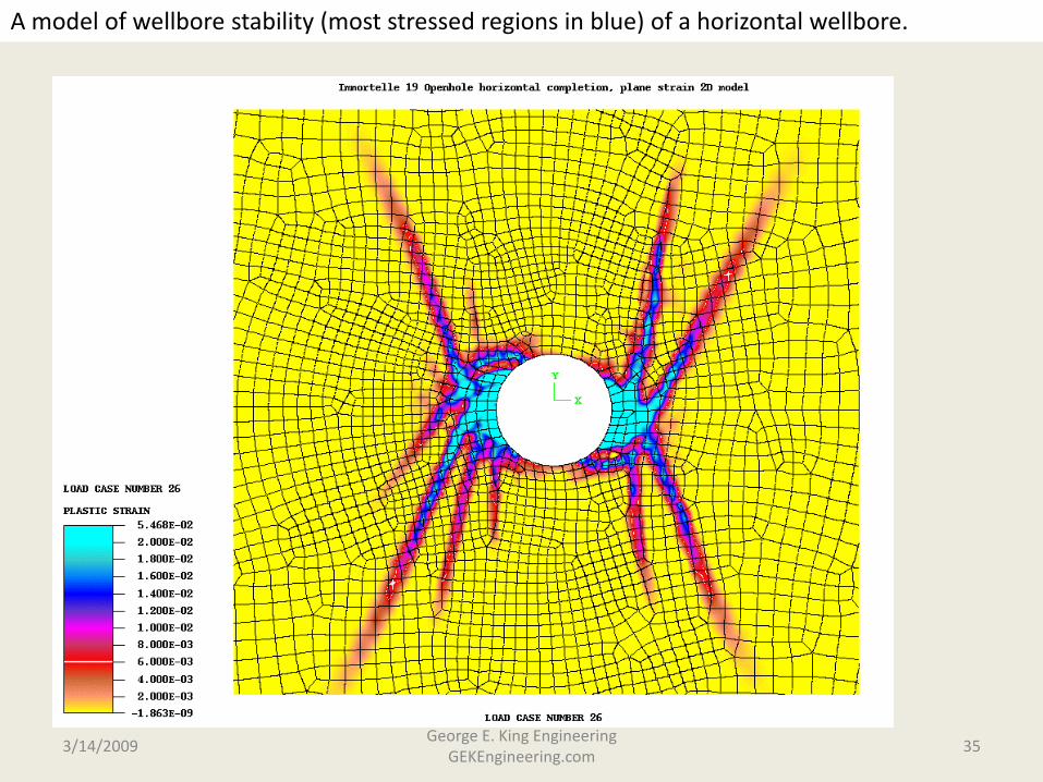
A model of wellbore stability (most stressed regions in blue) of a horizontal wellbore.
3/14/2009 35George E. King Engineering
GEKEngineering.com
Broad Based Conclusion
• Most Important Failure Factors– pore pressure prediction– weak, fissible beddling planes– low support pressures– time dependent loss of strength
• Open holes best in stable formations (carbonates, clastics)
• Most instability problems in the shales
3/14/2009 36George E. King Engineering
GEKEngineering.com

So, how far do you drill?
• Consider edge boundries
• Consider drilling costs (usually low in lateral)
• Consider vertical perm
3/14/2009 37George E. King Engineering
GEKEngineering.com
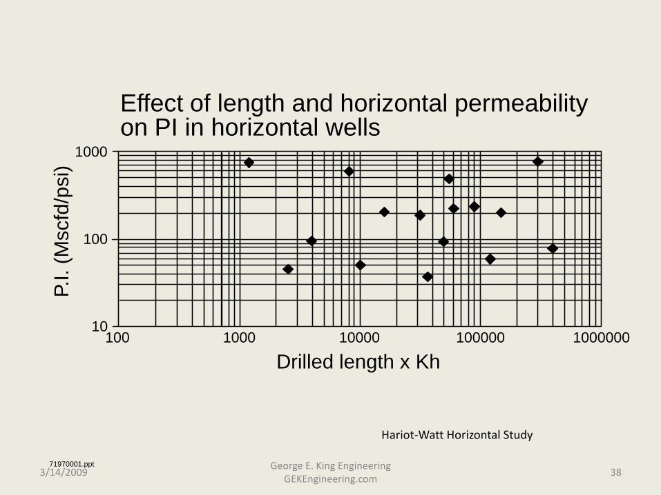
Effect of length and horizontal permeability on PI in horizontal wells
1000
100
10
P.I.
(Msc
fd/p
si)
100 1000 10000 100000 1000000
Drilled length x Kh
71970001.ppt3/14/2009 38
George E. King Engineering GEKEngineering.com
Hariot-Watt Horizontal Study
71970002.ppt
10000
1000
100
1010 100 1000 10000 100000 1000000
Length x (KvKh)^0.5
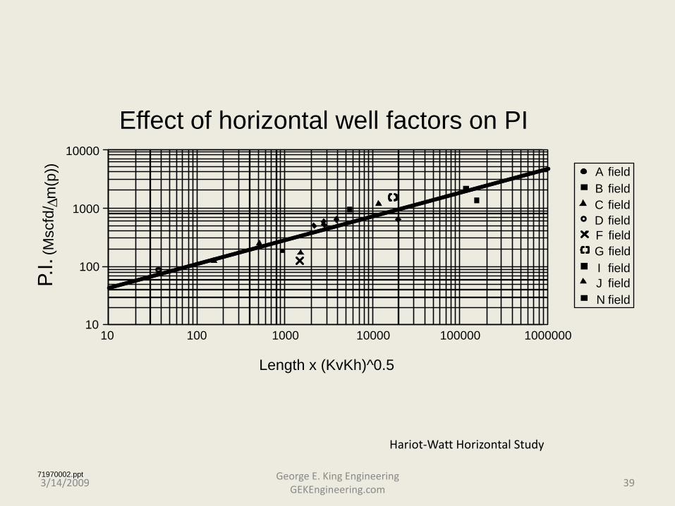
Effect of horizontal well factors on PI
A fieldB fieldC fieldD fieldF fieldG fieldI fieldJ fieldN field
P.I.
(Msc
fd/ ∆
m(p
))
3/14/2009 39George E. King Engineering
GEKEngineering.com
Hariot-Watt Horizontal Study
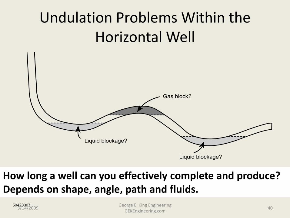
Undulation Problems Within the Horizontal Well
50423007
How long a well can you effectively complete and produce? Depends on shape, angle, path and fluids.
3/14/2009 40George E. King Engineering
GEKEngineering.com
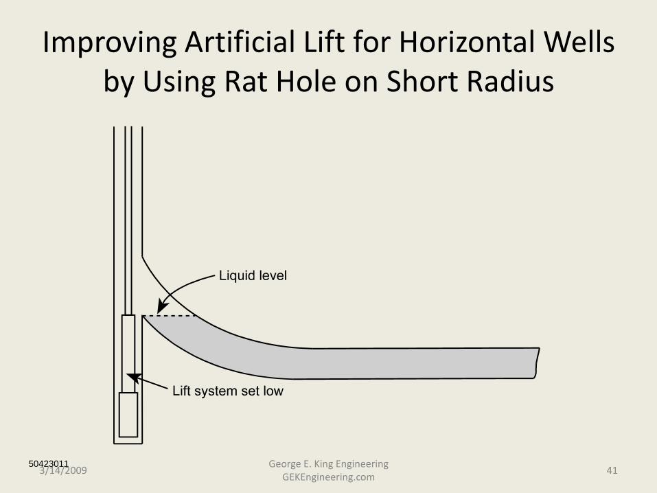
Improving Artificial Lift for Horizontal Wells by Using Rat Hole on Short Radius
504230113/14/2009 41
George E. King Engineering GEKEngineering.com
Production Index Factors
(a comparison to horizontal well performance)
• Theoritical PIF’s may range from 1 to 8.
• Actual PIF’s range from 1 to about 4 or 5.
• Causes:– reservoir not homogeneous
– reservoir “estimates” too generous
– completion design was an after-thought
3/14/2009 42George E. King Engineering
GEKEngineering.com
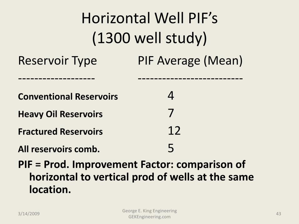
Horizontal Well PIF’s(1300 well study)
Reservoir Type PIF Average (Mean)------------------- --------------------------Conventional Reservoirs 4Heavy Oil Reservoirs 7Fractured Reservoirs 12All reservoirs comb. 5PIF = Prod. Improvement Factor: comparison of
horizontal to vertical prod of wells at the same location.
3/14/2009 43George E. King Engineering
GEKEngineering.com
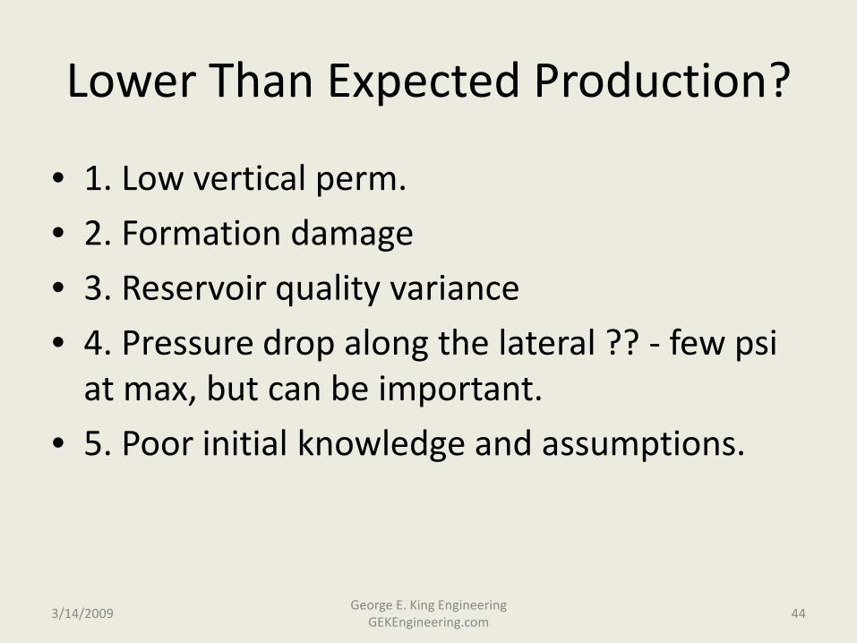
Lower Than Expected Production?
• 1. Low vertical perm.
• 2. Formation damage
• 3. Reservoir quality variance
• 4. Pressure drop along the lateral ?? - few psi at max, but can be important.
• 5. Poor initial knowledge and assumptions.
3/14/2009 44George E. King Engineering
GEKEngineering.com
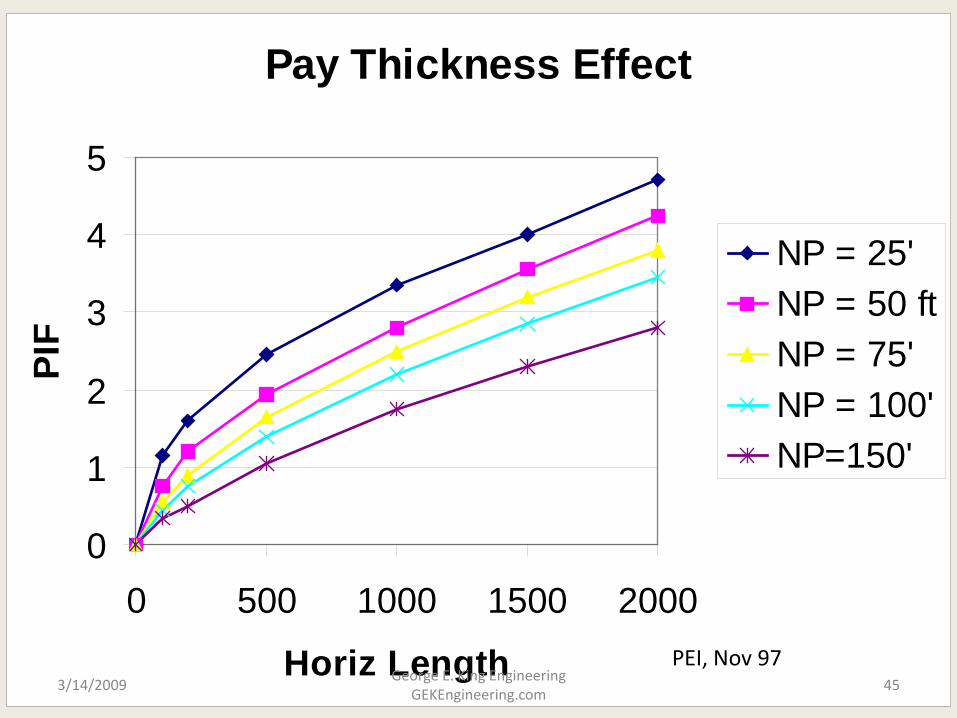
Pay Thickness Effect
0
1
2
3
4
5
0 500 1000 1500 2000
Horiz Length
PIF
NP = 25'NP = 50 ftNP = 75'NP = 100'NP=150'
PEI, Nov 973/14/2009 45
George E. King Engineering GEKEngineering.com
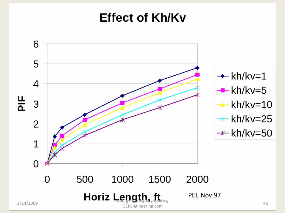
Effect of Kh/Kv
0
1
2
3
4
5
6
0 500 1000 1500 2000
Horiz Length, ft
PIF
kh/kv=1kh/kv=5kh/kv=10kh/kv=25kh/kv=50
PEI, Nov 973/14/2009 46
George E. King Engineering GEKEngineering.com
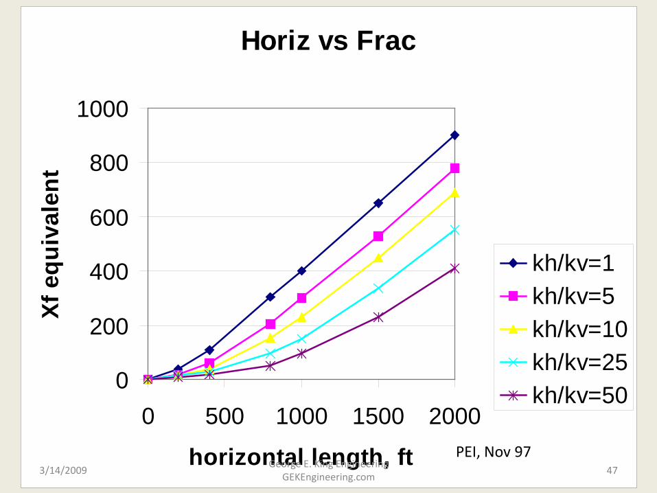
Horiz vs Frac
0
200
400
600
800
1000
0 500 1000 1500 2000
horizontal length, ft
Xf e
quiv
alen
t
kh/kv=1kh/kv=5kh/kv=10kh/kv=25kh/kv=50
PEI, Nov 973/14/2009 47
George E. King Engineering GEKEngineering.com
Horizontal Uses?
• Consider them any time a well is designed.
• Particularly good for:– Coning control,
– Extending reach,
– Increasing reservoir contact,
– Lowering drawdown per unit area,
– As a platform for multiple fracture stimulation
– In some water injector projects.
3/14/2009George E. King Engineering
GEKEngineering.com48