Embed Size (px)
Citation preview
GRADLLC.COM
HORIZONTAL
Basics:
HORIZONTAL WAVE FORMS
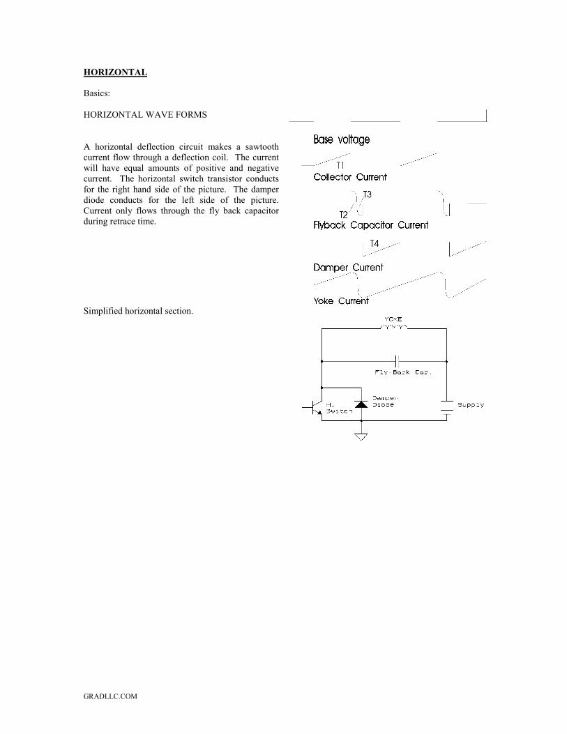
A horizontal deflection circuit makes a sawtoothcurrent flow through a deflection coil. The currentwill have equal amounts of positive and negativecurrent. The horizontal switch transistor conductsfor the right hand side of the picture. The damperdiode conducts for the left side of the picture.Current only flows through the fly back capacitorduring retrace time.
Simplified horizontal section.
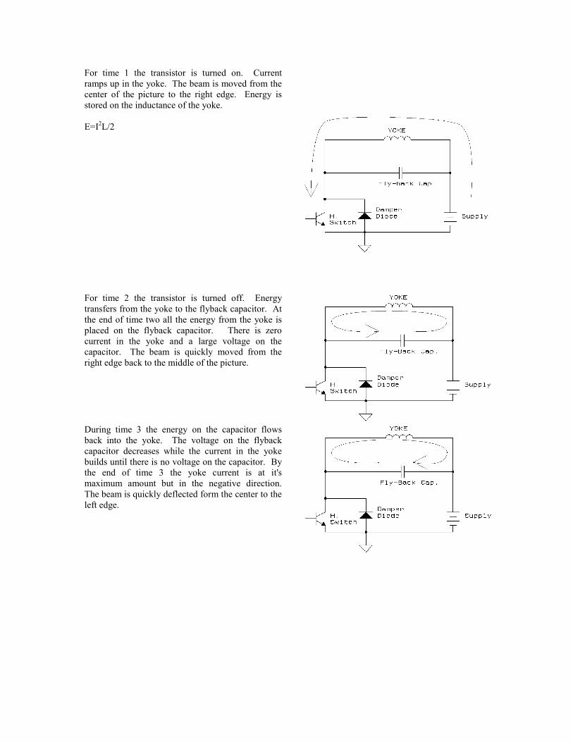
For time 1 the transistor is turned on. Currentramps up in the yoke. The beam is moved from thecenter of the picture to the right edge. Energy isstored on the inductance of the yoke.
E=I2L/2
For time 2 the transistor is turned off. Energytransfers from the yoke to the flyback capacitor. Atthe end of time two all the energy from the yoke isplaced on the flyback capacitor. There is zerocurrent in the yoke and a large voltage on thecapacitor. The beam is quickly moved from theright edge back to the middle of the picture.
During time 3 the energy on the capacitor flowsback into the yoke. The voltage on the flybackcapacitor decreases while the current in the yokebuilds until there is no voltage on the capacitor. Bythe end of time 3 the yoke current is at it'smaximum amount but in the negative direction.The beam is quickly deflected form the center to theleft edge.
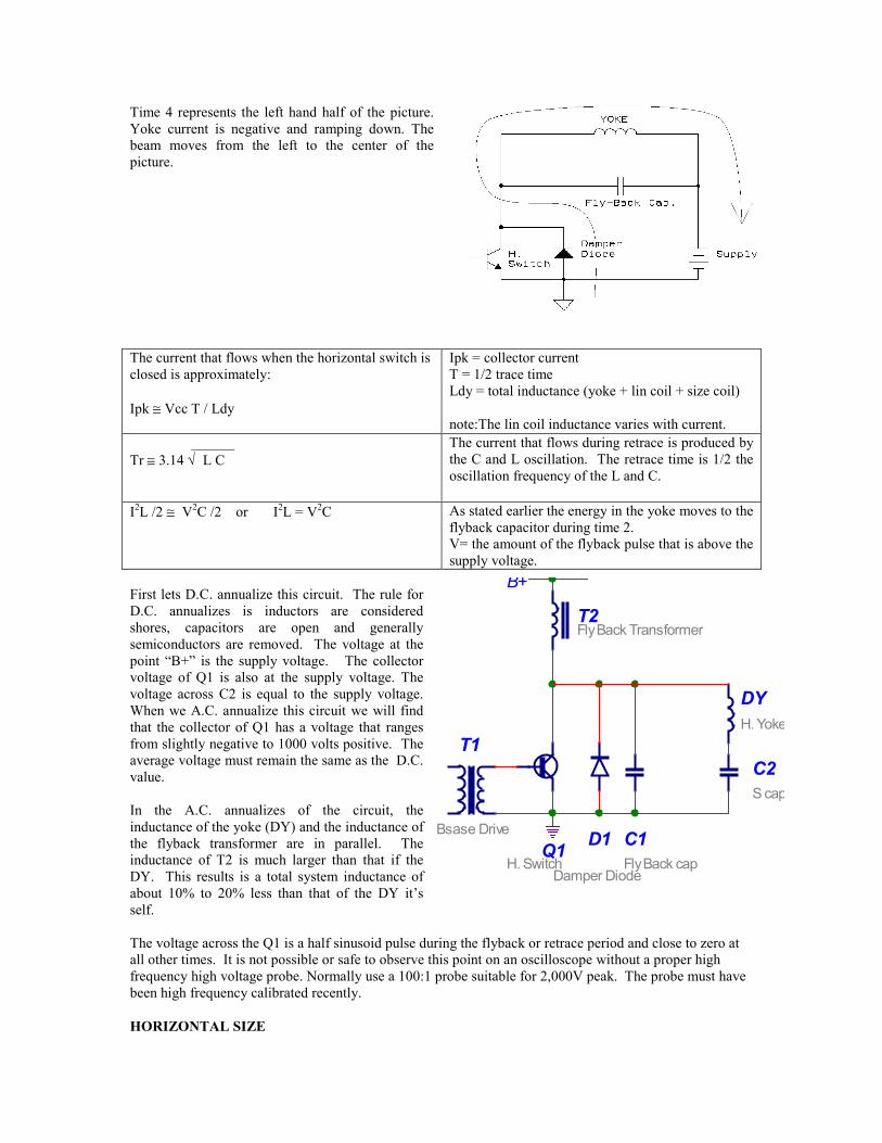
Time 4 represents the left hand half of the picture.Yoke current is negative and ramping down. Thebeam moves from the left to the center of thepicture.
The current that flows when the horizontal switch isclosed is approximately:
Ipk ≅ Vcc T / Ldy
Ipk = collector currentT = 1/2 trace timeLdy = total inductance (yoke + lin coil + size coil)
note:The lin coil inductance varies with current. ______Tr ≅ 3.14 √ L C
The current that flows during retrace is produced bythe C and L oscillation. The retrace time is 1/2 theoscillation frequency of the L and C.
I2L /2 ≅ V2C /2 or I2L = V2C As stated earlier the energy in the yoke moves to theflyback capacitor during time 2.V= the amount of the flyback pulse that is above thesupply voltage.
First lets D.C. annualize this circuit. The rule forD.C. annualizes is inductors are consideredshores, capacitors are open and generallysemiconductors are removed. The voltage at thepoint “B+” is the supply voltage. The collectorvoltage of Q1 is also at the supply voltage. Thevoltage across C2 is equal to the supply voltage.When we A.C. annualize this circuit we will findthat the collector of Q1 has a voltage that rangesfrom slightly negative to 1000 volts positive. Theaverage voltage must remain the same as the D.C.value.
In the A.C. annualizes of the circuit, theinductance of the yoke (DY) and the inductance ofthe flyback transformer are in parallel. Theinductance of T2 is much larger than that if theDY. This results is a total system inductance ofabout 10% to 20% less than that of the DY it’sself.
The voltage across the Q1 is a half sinusoid pulse during the flyback or retrace period and close to zero atall other times. It is not possible or safe to observe this point on an oscilloscope without a proper highfrequency high voltage probe. Normally use a 100:1 probe suitable for 2,000V peak. The probe must havebeen high frequency calibrated recently.
HORIZONTAL SIZE
T1
Bsase Drive C1Fly Back cap
C2S cap
D1
Damper DiodeQ1
H. Switch
DYH. Yoke
T2Fly Back Transformer
B+
There are several different methods of adjusting horizontal size.
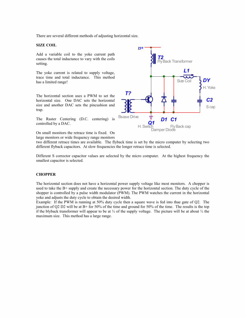
SIZE COIL
Add a variable coil to the yoke current pathcauses the total inductance to vary with the coilssetting.
The yoke current is related to supply voltage,trace time and total inductance. This methodhas a limited range!
The horizontal section uses a PWM to set thehorizontal size. One DAC sets the horizontalsize and another DAC sets the pincushion andtrap.
The Raster Centering (D.C. centering) iscontrolled by a DAC.
On small monitors the retrace time is fixed. Onlarge monitors or wide frequency range monitorstwo different retrace times are available. The flyback time is set by the micro computer by selecting twodifferent flyback capacitors. At slow frequencies the longer retrace time is selected.
Different S corrector capacitor values are selected by the micro computer. At the highest frequency thesmallest capacitor is selected.
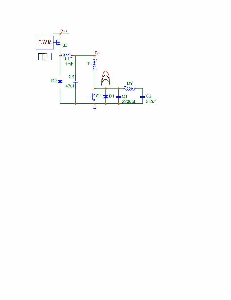
CHOPPER
The horizontal section does not have a horizontal power supply voltage like most monitors. A chopper isused to take the B+ supply and create the necessary power for the horizontal section. The duty cycle of theshopper is controlled by a pulse width modulator (PWM). The PWM watches the current in the horizontalyoke and adjusts the duty cycle to obtain the desired width.Example: If the PWM is running at 50% duty cycle then a square wave is fed into thae gate of Q2. Thejunction of Q2 D2 will be at B+ for 50% of the time and ground for 50% of the time. The results is the topif the blyback transformer will appear to be at ½ of the supply voltage. The picture will be at about ½ themaximum size. This method has a large range.
T?
Bsase Drive C1Fly Back cap
C2S cap
D1
Damper DiodeQ1
H. Switch
DYH. Yoke
T2Fly Back Transformer
B+
L1
Size Coil
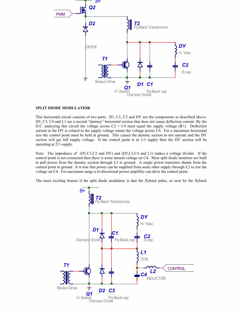
SPLIT DIODE MODULATIOR
This horizontal circuit consists of two parts. D1, C1, C2 and DY are the components as described above.D2, C3, C4 and L1 are a second “dummy” horizontal section that does not cause deflection current. By theD.C. analyzing this circuit the voltage across C2 + C4 must equal the supply voltage (B+). Deflectioncurrent in the DY is related to the supply voltage minus the voltage across C4. For a maximum horizontalsize the control point must be held at ground. This causes the dummy section to not operate and the DYsection will get full supply voltage. If the control point is at 1/3 supply then the DY section will beoperating at 2/3 supply.
Note: The impedance of (D1,C1,C2 and DY) and (D2,C3,C4 and L1) makes a voltage divider. If thecontrol point is not connected then there is some natural voltage on C4. Most split diode monitors are builtto pull power from the dummy section through L2 to ground. A single power transistor shunts from thecontrol point to ground. It is true that power can be supplied from some other supply through L2 to rise thevoltage on C4. For maximum range a bi-directional power amplifier can drive the control point.
The most exciting feature if the split diode modulator is that the flyback pulse, as seen by the flyback
PWM
T1
Bsase Drive C1Fly Back cap
C2S cap
D1
Damper Diode
Q1H. Switch
DYH. Yoke
T2Fly Back Transformer
B+
D2
DIODE
Q2
CONTROLT1
Bsase Drive C3Fly Back cap
C4
D2
Damper Diode
Q1H. Switch
L1COIL
T2Fly Back Transformer
C1Fly Back cap
C2S cap
D1
Damper Diode
DYH. Yoke
L2INDUCTOR
B+
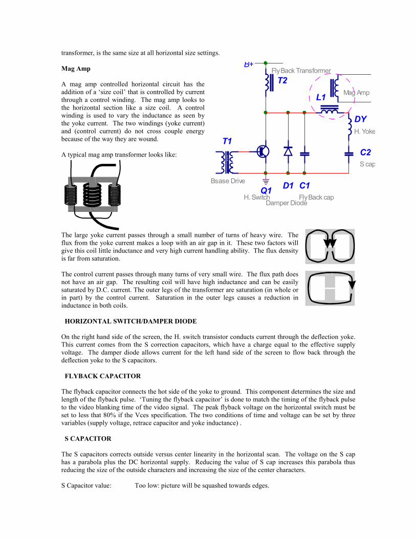
transformer, is the same size at all horizontal size settings.
Mag Amp
A mag amp controlled horizontal circuit has theaddition of a ‘size coil’ that is controlled by currentthrough a control winding. The mag amp looks tothe horizontal section like a size coil. A controlwinding is used to vary the inductance as seen bythe yoke current. The two windings (yoke current)and (control current) do not cross couple energybecause of the way they are wound.
A typical mag amp transformer looks like:
The large yoke current passes through a small number of turns of heavy wire. Theflux from the yoke current makes a loop with an air gap in it. These two factors willgive this coil little inductance and very high current handling ability. The flux densityis far from saturation.
The control current passes through many turns of very small wire. The flux path doesnot have an air gap. The resulting coil will have high inductance and can be easilysaturated by D.C. current. The outer legs of the transformer are saturation (in whole orin part) by the control current. Saturation in the outer legs causes a reduction ininductance in both coils.
HORIZONTAL SWITCH/DAMPER DIODE
On the right hand side of the screen, the H. switch transistor conducts current through the deflection yoke.This current comes from the S correction capacitors, which have a charge equal to the effective supplyvoltage. The damper diode allows current for the left hand side of the screen to flow back through thedeflection yoke to the S capacitors.
FLYBACK CAPACITOR
The flyback capacitor connects the hot side of the yoke to ground. This component determines the size andlength of the flyback pulse. ‘Tuning the flyback capacitor’ is done to match the timing of the flyback pulseto the video blanking time of the video signal. The peak flyback voltage on the horizontal switch must beset to less that 80% if the Vces specification. The two conditions of time and voltage can be set by threevariables (supply voltage, retrace capacitor and yoke inductance) .
S CAPACITOR
The S capacitors corrects outside versus center linearity in the horizontal scan. The voltage on the S caphas a parabola plus the DC horizontal supply. Reducing the value of S cap increases this parabola thusreducing the size of the outside characters and increasing the size of the center characters.
S Capacitor value: Too low: picture will be squashed towards edges.
T1
Bsase Drive C1Fly Back cap
C2S cap
D1
Damper Diode
Q1H. Switch
DYH. Yoke
T2Fly Back Transformer
B+
L1 Mag Amp
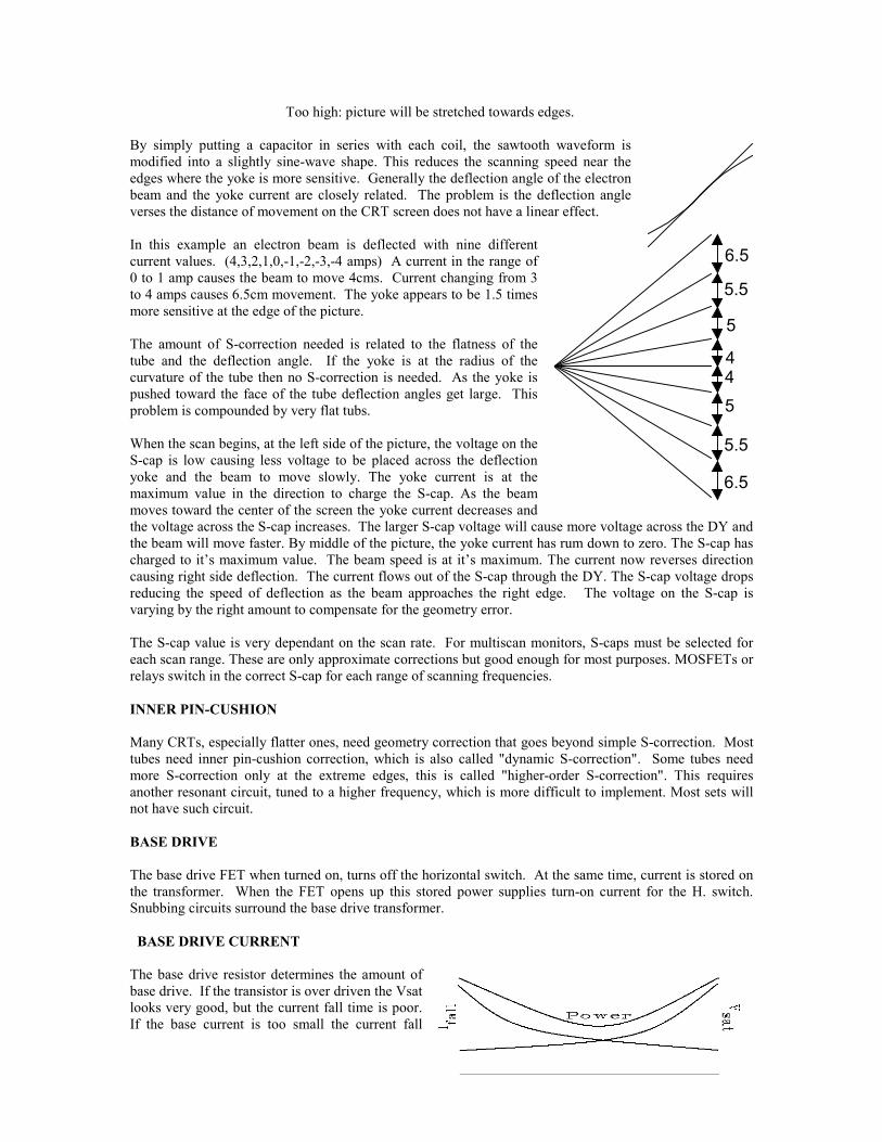
Too high: picture will be stretched towards edges.
By simply putting a capacitor in series with each coil, the sawtooth waveform ismodified into a slightly sine-wave shape. This reduces the scanning speed near theedges where the yoke is more sensitive. Generally the deflection angle of the electronbeam and the yoke current are closely related. The problem is the deflection angleverses the distance of movement on the CRT screen does not have a linear effect.
In this example an electron beam is deflected with nine differentcurrent values. (4,3,2,1,0,-1,-2,-3,-4 amps) A current in the range of0 to 1 amp causes the beam to move 4cms. Current changing from 3to 4 amps causes 6.5cm movement. The yoke appears to be 1.5 timesmore sensitive at the edge of the picture.
The amount of S-correction needed is related to the flatness of thetube and the deflection angle. If the yoke is at the radius of thecurvature of the tube then no S-correction is needed. As the yoke ispushed toward the face of the tube deflection angles get large. Thisproblem is compounded by very flat tubs.
When the scan begins, at the left side of the picture, the voltage on theS-cap is low causing less voltage to be placed across the deflectionyoke and the beam to move slowly. The yoke current is at themaximum value in the direction to charge the S-cap. As the beammoves toward the center of the screen the yoke current decreases andthe voltage across the S-cap increases. The larger S-cap voltage will cause more voltage across the DY andthe beam will move faster. By middle of the picture, the yoke current has rum down to zero. The S-cap hascharged to it’s maximum value. The beam speed is at it’s maximum. The current now reverses directioncausing right side deflection. The current flows out of the S-cap through the DY. The S-cap voltage dropsreducing the speed of deflection as the beam approaches the right edge. The voltage on the S-cap isvarying by the right amount to compensate for the geometry error.
The S-cap value is very dependant on the scan rate. For multiscan monitors, S-caps must be selected foreach scan range. These are only approximate corrections but good enough for most purposes. MOSFETs orrelays switch in the correct S-cap for each range of scanning frequencies.
INNER PIN-CUSHION
Many CRTs, especially flatter ones, need geometry correction that goes beyond simple S-correction. Mosttubes need inner pin-cushion correction, which is also called "dynamic S-correction". Some tubes needmore S-correction only at the extreme edges, this is called "higher-order S-correction". This requiresanother resonant circuit, tuned to a higher frequency, which is more difficult to implement. Most sets willnot have such circuit.
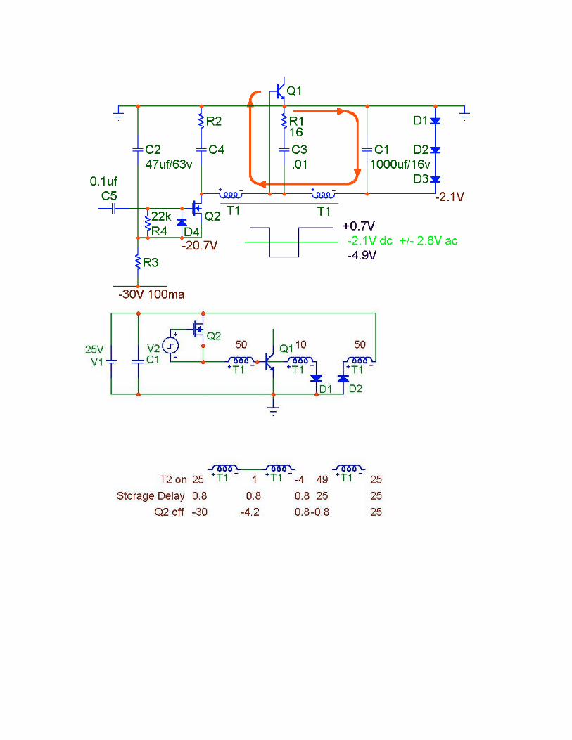
BASE DRIVE
The base drive FET when turned on, turns off the horizontal switch. At the same time, current is stored onthe transformer. When the FET opens up this stored power supplies turn-on current for the H. switch.Snubbing circuits surround the base drive transformer.
BASE DRIVE CURRENT
The base drive resistor determines the amount ofbase drive. If the transistor is over driven the Vsatlooks very good, but the current fall time is poor.If the base current is too small the current fall
45
5.5
6.5
4
5
5.5
6.5
time is very fast. The problem is that the transistor will have many volts across C-E when closed.
The best condition is found by placing the transistor in the heaviest load condition. Adjust the base resistorfor the least power consumption then increase the base drive a small amount. This will slightly over drivethe base.Through the base drive DAC the micro computer can make changes in base drive current to compensate forfrequency changes. This option is only available on the larger monitors.
HORIZONTAL LINEARITY
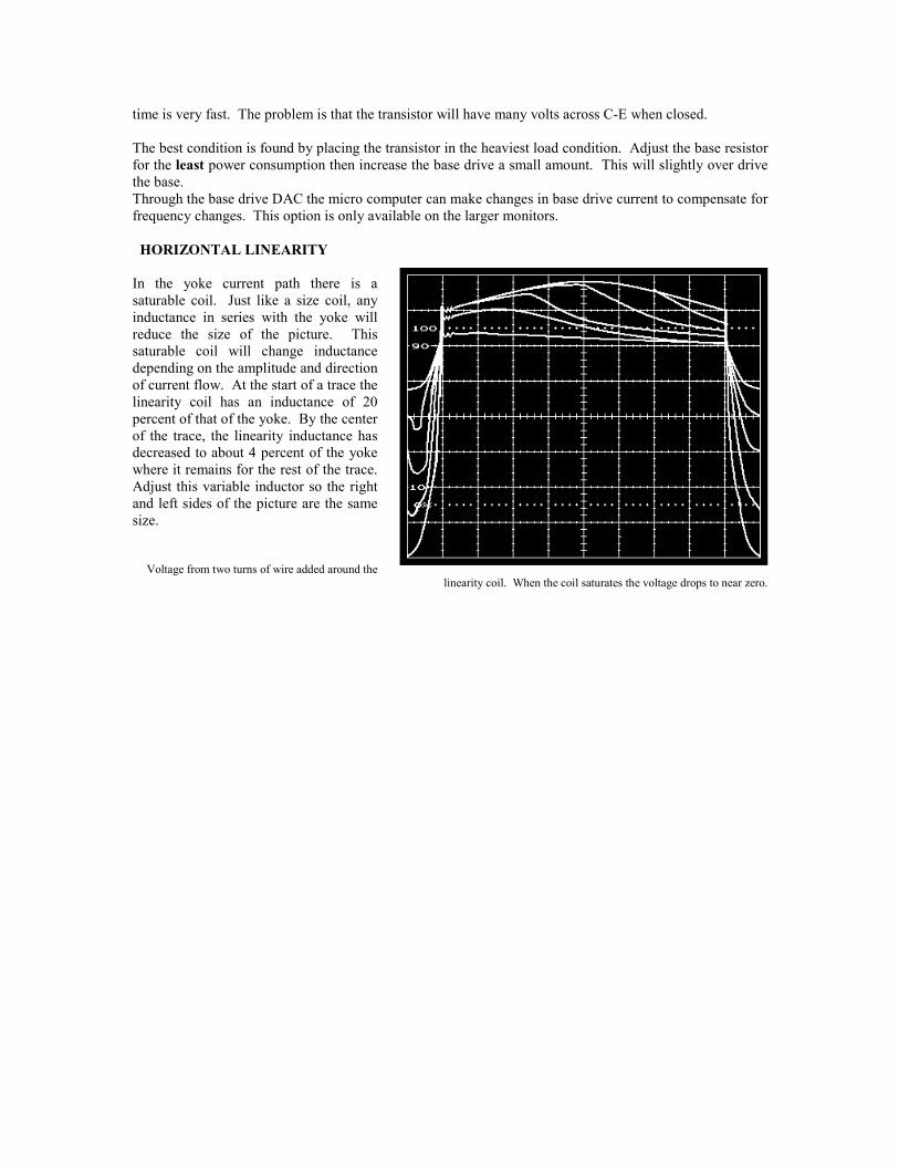
In the yoke current path there is asaturable coil. Just like a size coil, anyinductance in series with the yoke willreduce the size of the picture. Thissaturable coil will change inductancedepending on the amplitude and directionof current flow. At the start of a trace thelinearity coil has an inductance of 20percent of that of the yoke. By the centerof the trace, the linearity inductance hasdecreased to about 4 percent of the yokewhere it remains for the rest of the trace.Adjust this variable inductor so the rightand left sides of the picture are the samesize.
Voltage from two turns of wire added around thelinearity coil. When the coil saturates the voltage drops to near zero.
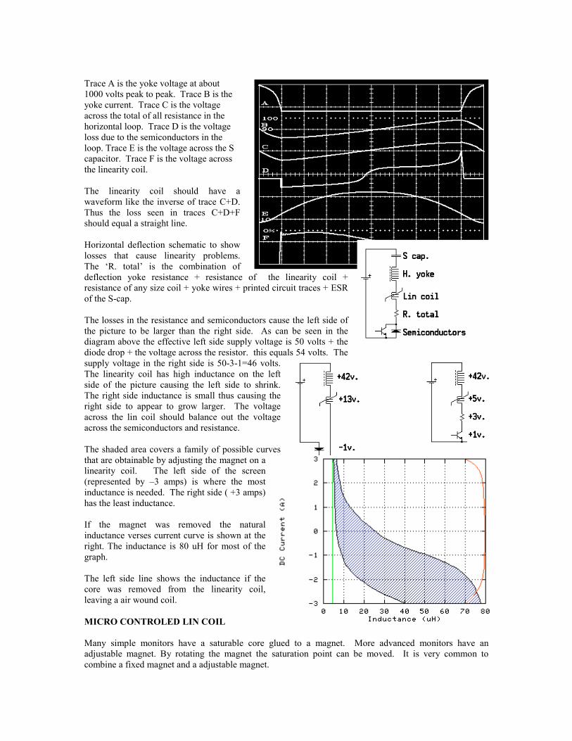
Trace A is the yoke voltage at about1000 volts peak to peak. Trace B is theyoke current. Trace C is the voltageacross the total of all resistance in thehorizontal loop. Trace D is the voltageloss due to the semiconductors in theloop. Trace E is the voltage across the Scapacitor. Trace F is the voltage acrossthe linearity coil.
The linearity coil should have awaveform like the inverse of trace C+D.Thus the loss seen in traces C+D+Fshould equal a straight line.
Horizontal deflection schematic to showlosses that cause linearity problems.The ‘R. total’ is the combination ofdeflection yoke resistance + resistance of the linearity coil +resistance of any size coil + yoke wires + printed circuit traces + ESRof the S-cap.
The losses in the resistance and semiconductors cause the left side ofthe picture to be larger than the right side. As can be seen in thediagram above the effective left side supply voltage is 50 volts + thediode drop + the voltage across the resistor. this equals 54 volts. Thesupply voltage in the right side is 50-3-1=46 volts.The linearity coil has high inductance on the leftside of the picture causing the left side to shrink.The right side inductance is small thus causing theright side to appear to grow larger. The voltageacross the lin coil should balance out the voltageacross the semiconductors and resistance.
The shaded area covers a family of possible curvesthat are obtainable by adjusting the magnet on alinearity coil. The left side of the screen(represented by –3 amps) is where the mostinductance is needed. The right side ( +3 amps)has the least inductance.
If the magnet was removed the naturalinductance verses current curve is shown at theright. The inductance is 80 uH for most of thegraph.
The left side line shows the inductance if thecore was removed from the linearity coil,leaving a air wound coil.
MICRO CONTROLED LIN COIL
Many simple monitors have a saturable core glued to a magnet. More advanced monitors have anadjustable magnet. By rotating the magnet the saturation point can be moved. It is very common tocombine a fixed magnet and a adjustable magnet.
By the time multi-sync monitors became popular design engineers were placing multiple linearity coils inthe deflection circuits. The problem is how to switch in the right coil. Relays and FETs have been usedwith varying degrees of success. If a monitor has two lin coils then there is only really only two horizontalfrequencies where the linearity is correct.
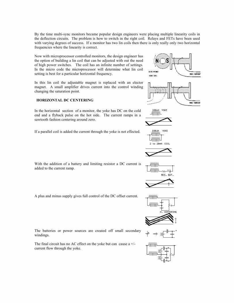
Now with microprocessor controlled monitors, the design engineer hasthe option of building a lin coil that can be adjusted with out the needof high power switches. The coil has an infinite number of settings.In the micro code the microprocessor will determine what lin coilsetting is best for a particular horizontal frequency.
In this lin coil the adjustable magnet is replaced with an electormagnet. A small amplifier drives current into the control windingchanging the saturation point.
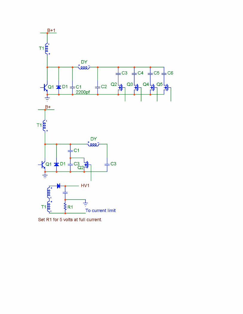
HORIZONTAL DC CENTERING
In the horizontal section of a monitor, the yoke has DC on the coldend and a flyback pulse on the hot side. The current ramps in asawtooth fashion centering around zero.
If a parallel coil is added the current through the yoke is not effected.
With the addition of a battery and limiting resistor a DC current isadded to the current ramp.
A plus and minus supply gives full control of the DC offset current.
The batteries or power sources are created off small secondarywindings.
The final circuit has no AC effect on the yoke but can cause a +/-current flow through the yoke.
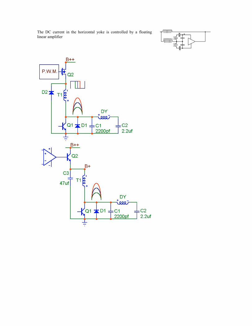
The DC current in the horizontal yoke is controlled by a floatinglinear amplifier