Embed Size (px)
Citation preview
Mark Pankuch PhD
AAPM MidWest Chapter
April 25 2015
Horizontal Plane Computed Tomography
CT’s in the seated position

Today's Discussion
•Define the potential capacity issues as we implement Pencil Beam Scanning in the Gantry room 4
• Introduce a potential solution : the Horizontal Plane CT scanner
• Share some design concepts
•Reach out for potential collaborations
2

Proton Center Beam Delivery System
IBTR3 IBTR2 GTR4 FBTR1
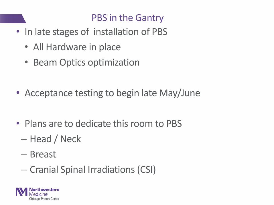
• In late stages of installation of PBS
• All Hardware in place
• Beam Optics optimization
• Acceptance testing to begin late May/June
• Plans are to dedicate this room to PBS
Head / Neck
Breast
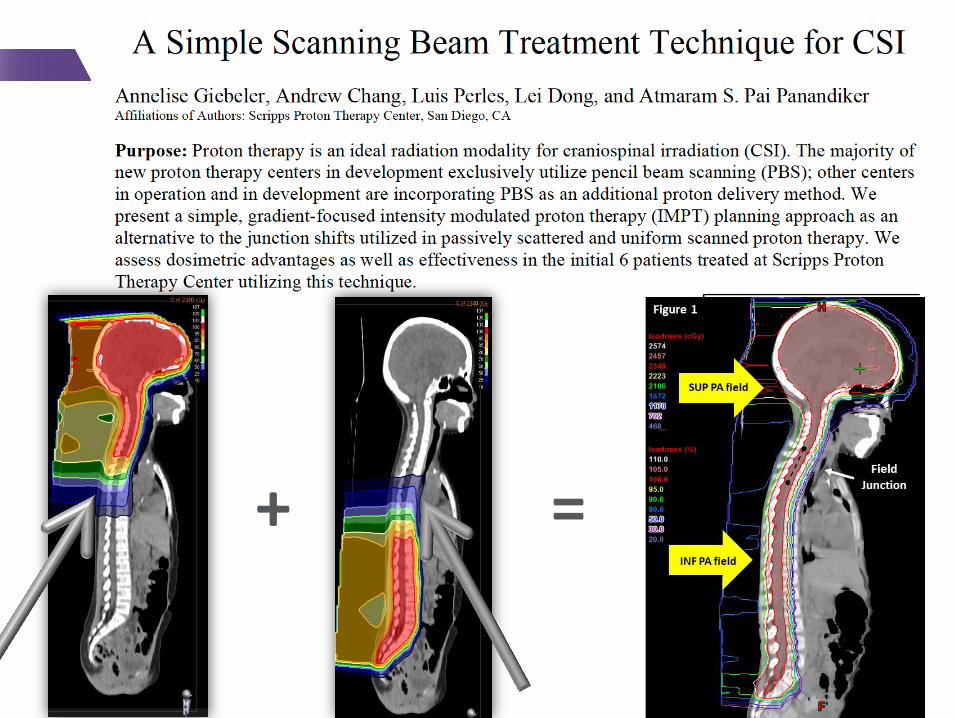
Cranial Spinal Irradiations (CSI)
PBS in the Gantry

Head / Neck with PBS
5
Proton PBS Photon IMRT

Stage 3, Left Breast/Chestwall + IMN
6
7
+ =
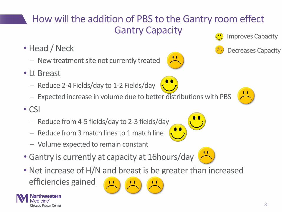
How will the addition of PBS to the Gantry room effect Gantry Capacity
• Head / Neck New treatment site not currently treated
• Lt Breast Reduce 2-4 Fields/day to 1-2 Fields/day
Expected increase in volume due to better distributions with PBS
• CSI Reduce from 4-5 fields/day to 2-3 fields/day
Reduce from 3 match lines to 1 match line
Volume expected to remain constant
• Gantry is currently at capacity at 16hours/day
• Net increase of H/N and breast is be greater than increased efficiencies gained
8
Improves Capacity
Decreases Capacity
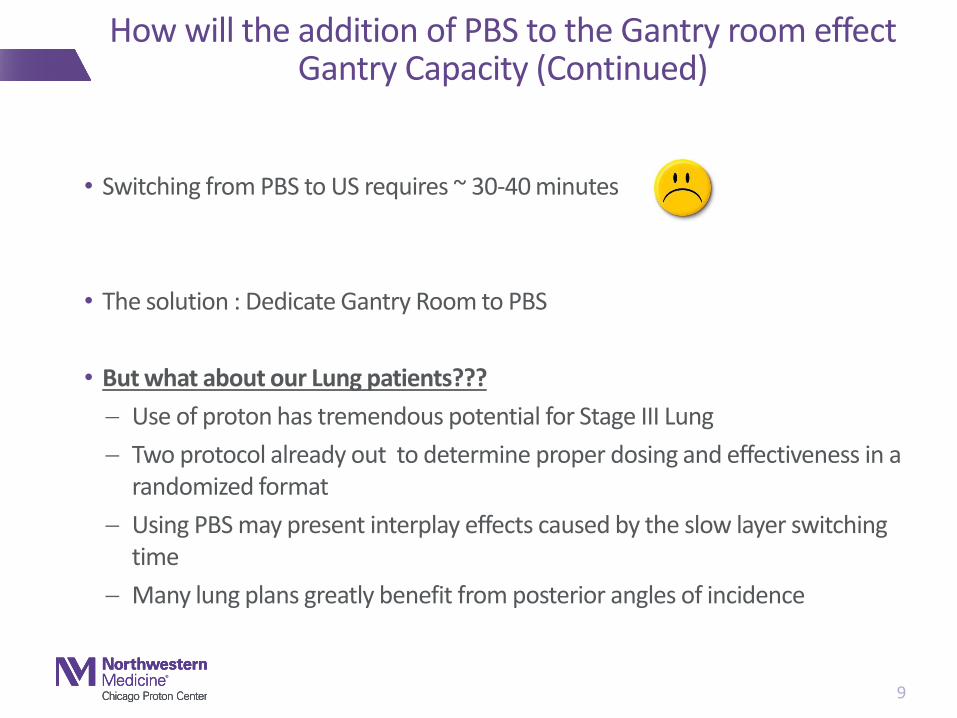
How will the addition of PBS to the Gantry room effect Gantry Capacity (Continued)
• Switching from PBS to US requires ~ 30-40 minutes
• The solution : Dedicate Gantry Room to PBS
• But what about our Lung patients???
Use of proton has tremendous potential for Stage III Lung
Two protocol already out to determine proper dosing and effectiveness in a randomized format
Using PBS may present interplay effects caused by the slow layer switching time
Many lung plans greatly benefit from posterior angles of incidence
9
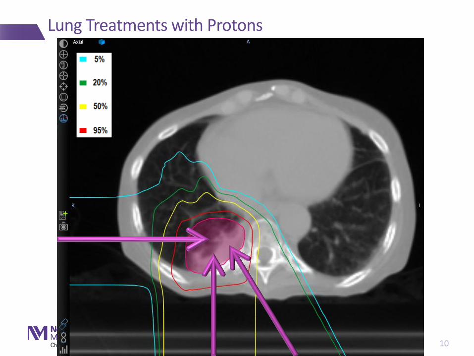
Lung Treatments with Protons
10
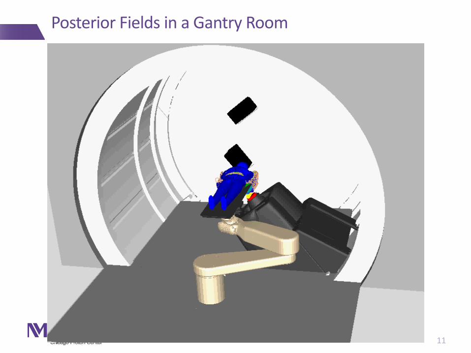
Posterior Fields in a Gantry Room
11
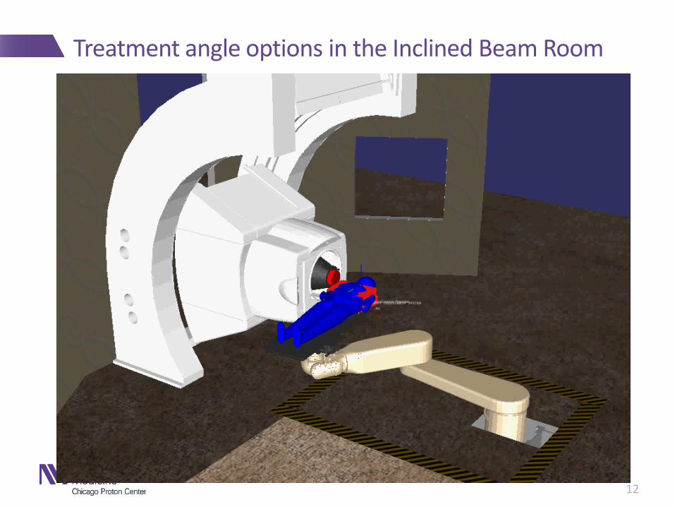
Treatment angle options in the Inclined Beam Room
12

Lung Treatments in the Incline Beam Line
13

Supine vs. Prone : Areas of motion
14
Supine Treatment Prone Treatment

Consider treatment is seated position
15
16
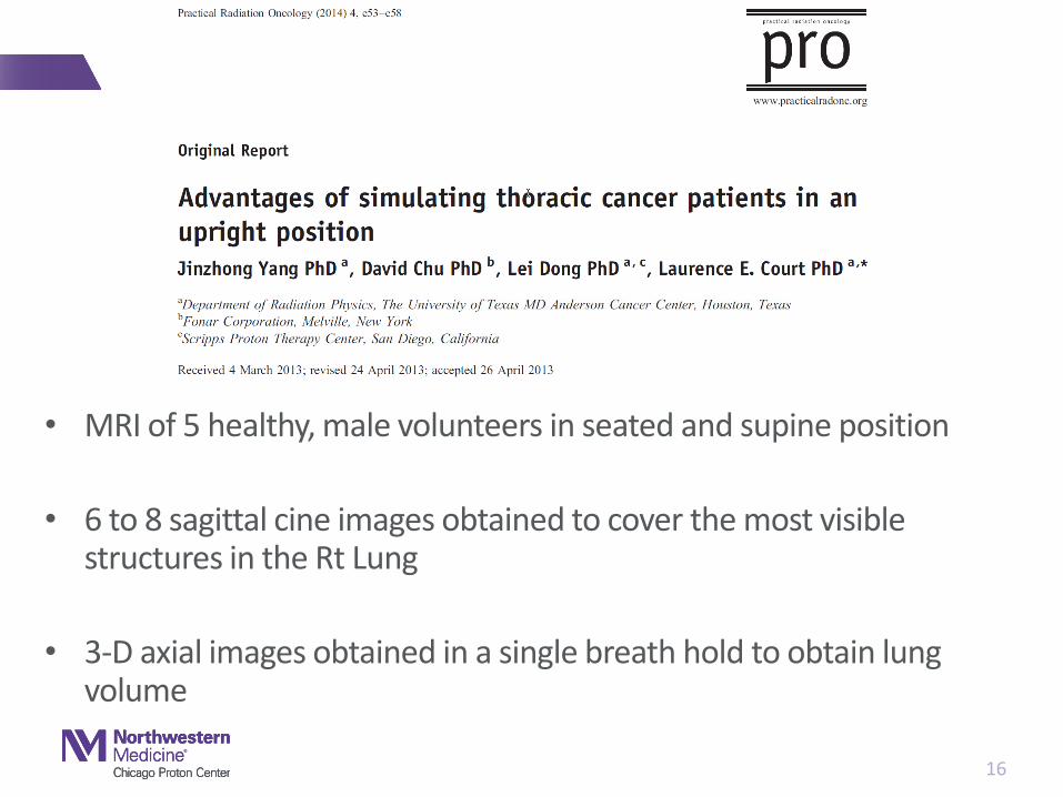
• MRI of 5 healthy, male volunteers in seated and supine position
• 6 to 8 sagittal cine images obtained to cover the most visible structures in the Rt Lung
• 3-D axial images obtained in a single breath hold to obtain lung volume

Determination of Magnitude of Sup/Inf Motion
• Sagittal cine MRI
• Trajectory of clear landmarks were determined
• Magnitude of internal breathing obtained for several points with >2mm of motion
• Positions normalized to distances from the diaphragm
0.0 at diaphragm
1.0 at lung apex
17
- 0.0
- 1.0
18
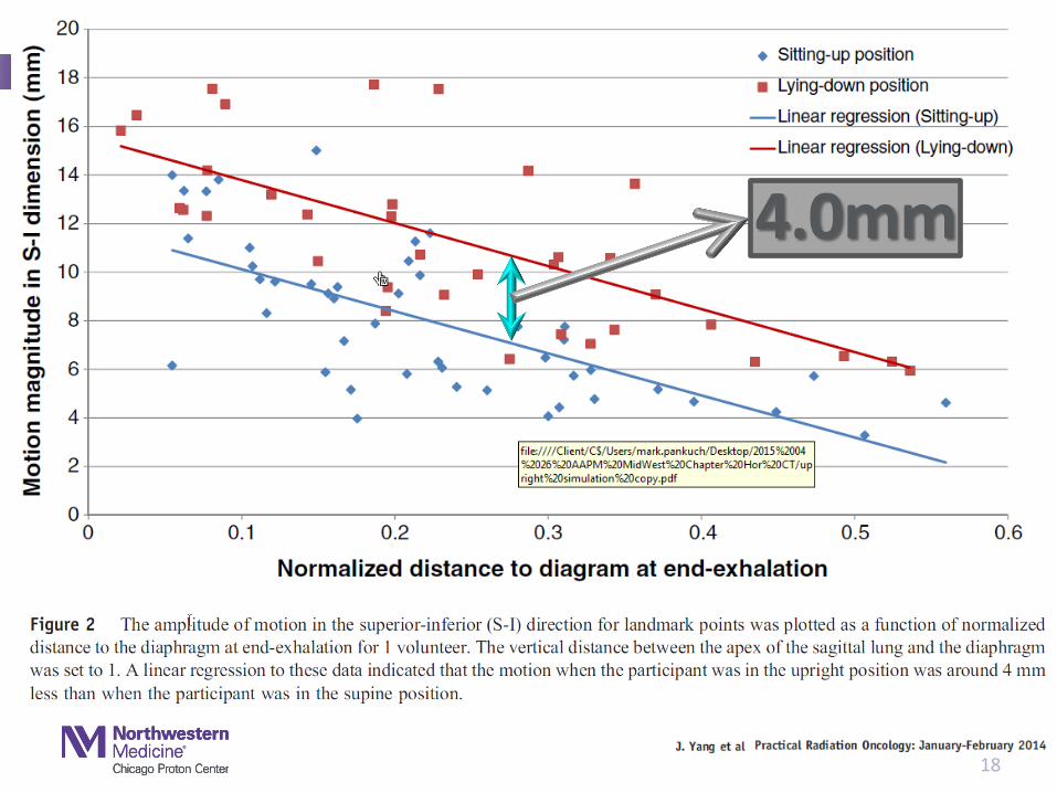
4.0mm

Average Motion Magnitude Difference
19
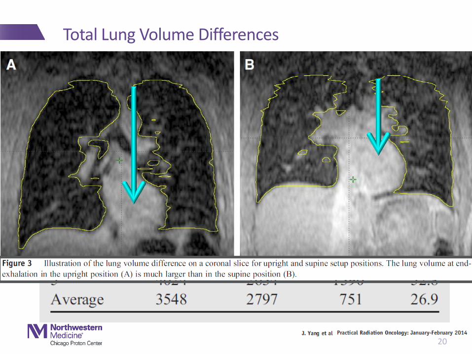
Total Lung Volume Differences
20
• Increase Lung volume
• Decrease lung motion
• Displaces the heart
• Provide us the opportunity to treat with US in IBL with Gantry-like field arrangements
• Less sensitive to interplay effects
• The answer for us :
• Treatment in the seated position
• Horizontal Plane scanner
Treatment In the seated position has potential benefits

P-Cure Solution \ Phillips Large Bore CT Scanner
22
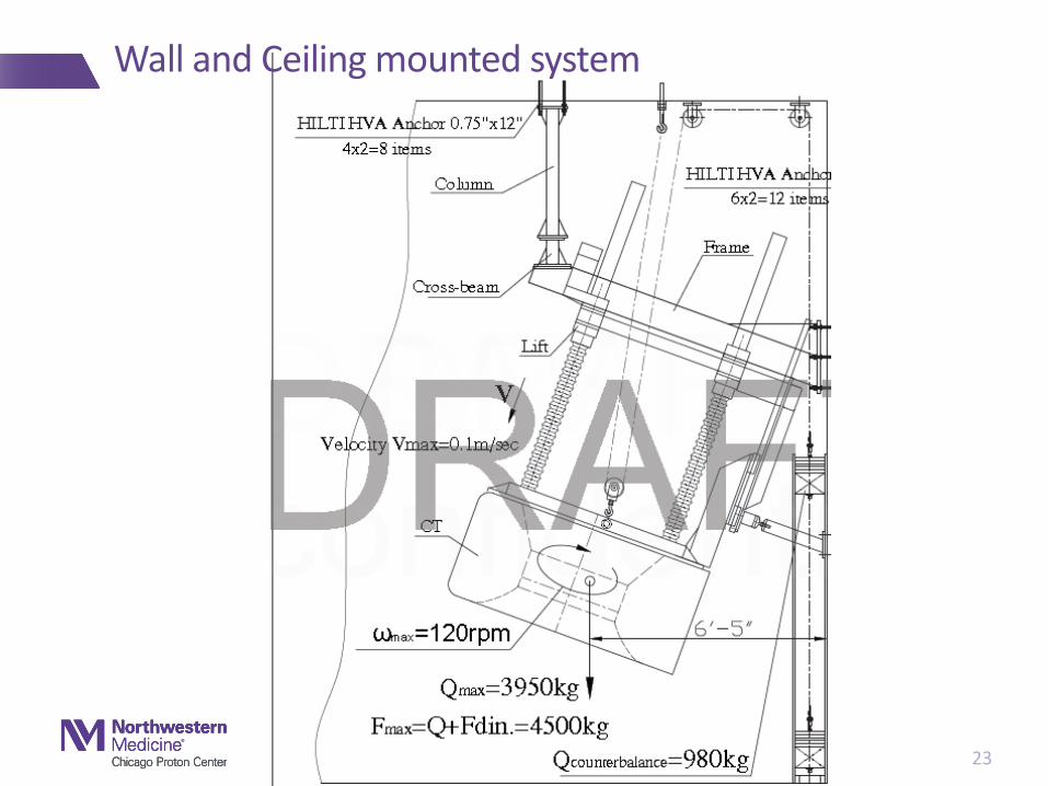
Wall and Ceiling mounted system
23

Wall Mounted System in IBL3
24
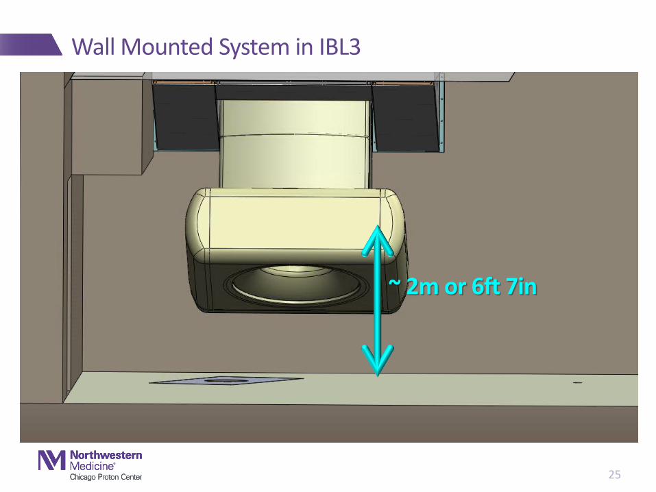
Wall Mounted System in IBL3
25
~ 2m or 6ft 7in
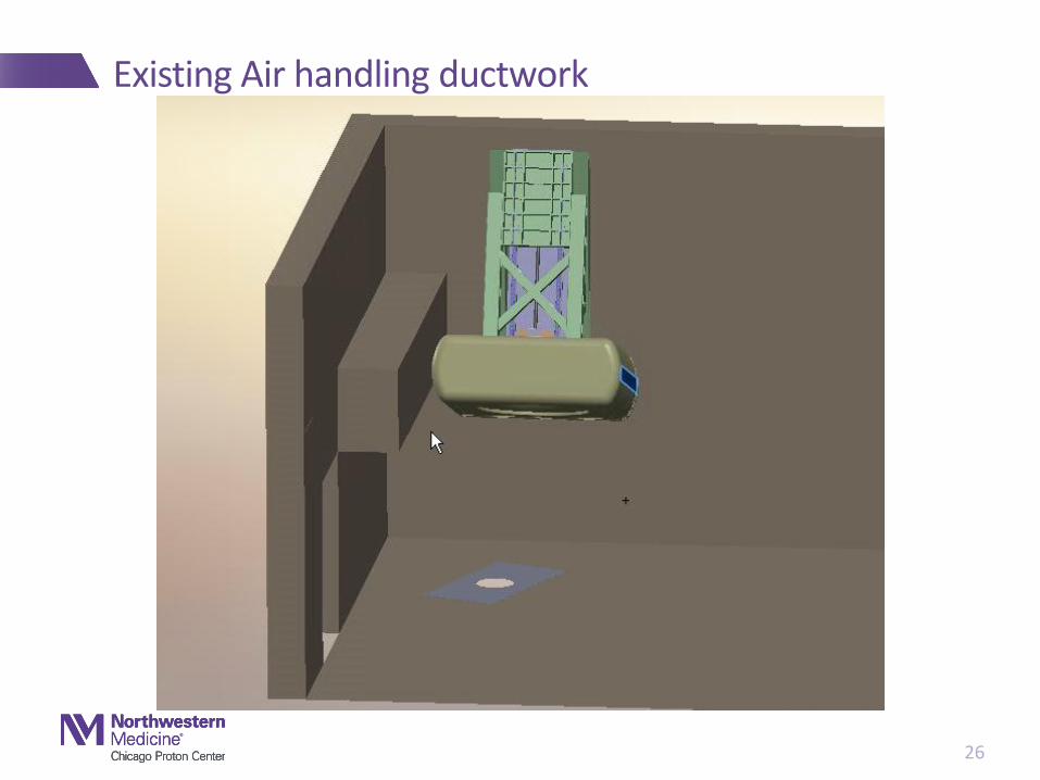
Existing Air handling ductwork
26
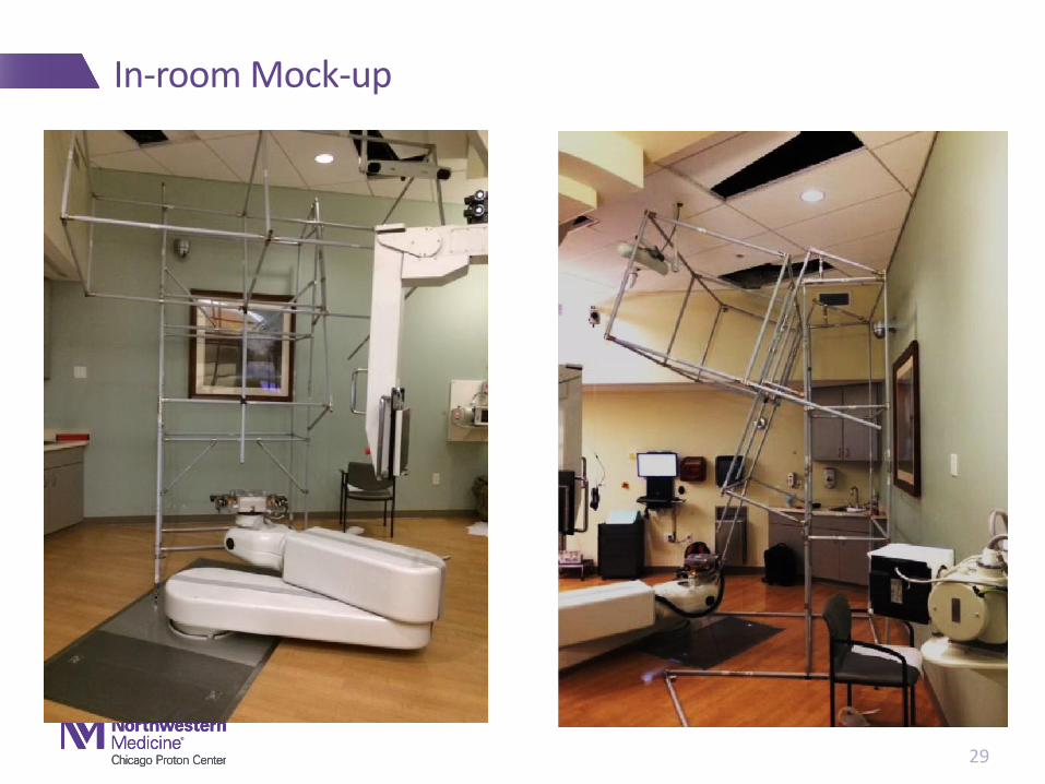
In-room Mock-up
29

Functional system with collision guard
30
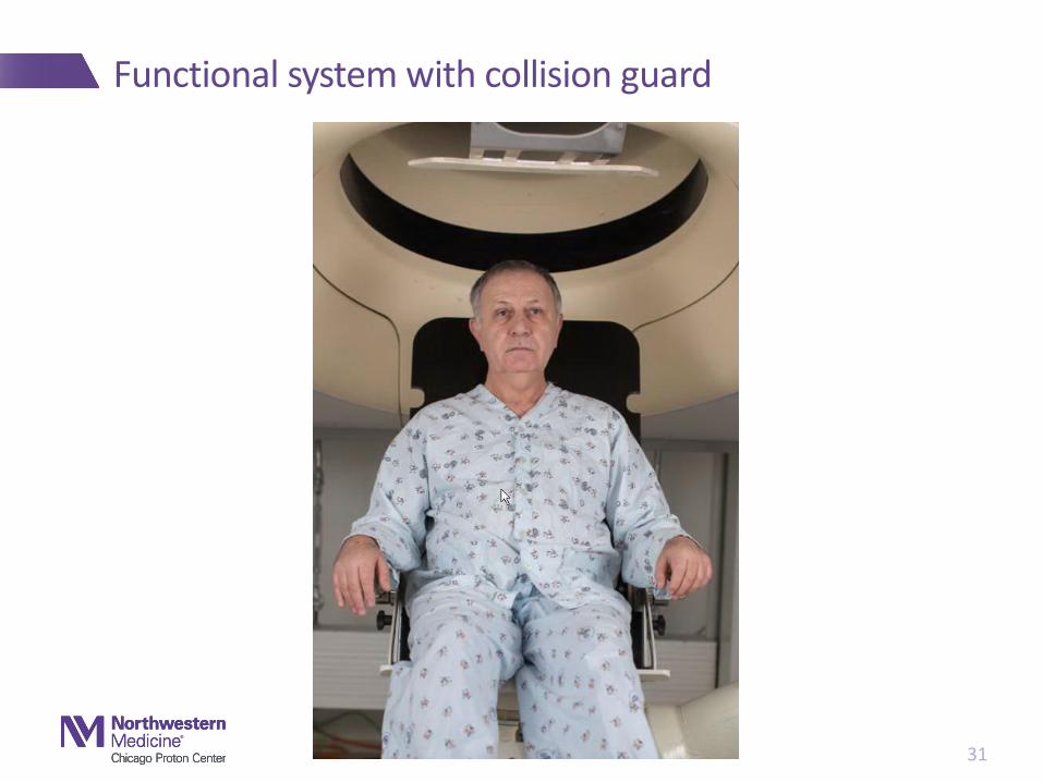
Functional system with collision guard
31
Thoracic chair - requirements
• Patient comfort
• Must be able to treat through the backrest
• Must attach to the top of the PPS wrist – full 360 degree rotation
• Weight limit – 400 lbs
• Interchangeable backrest with Unique IDs
• Must be able to scan below the diaphragm
33

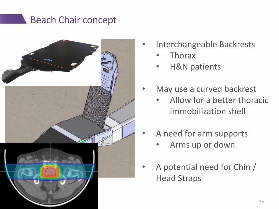
Beach Chair concept
34
Wing Board Attachment
PPS attaches to the chair under the knees
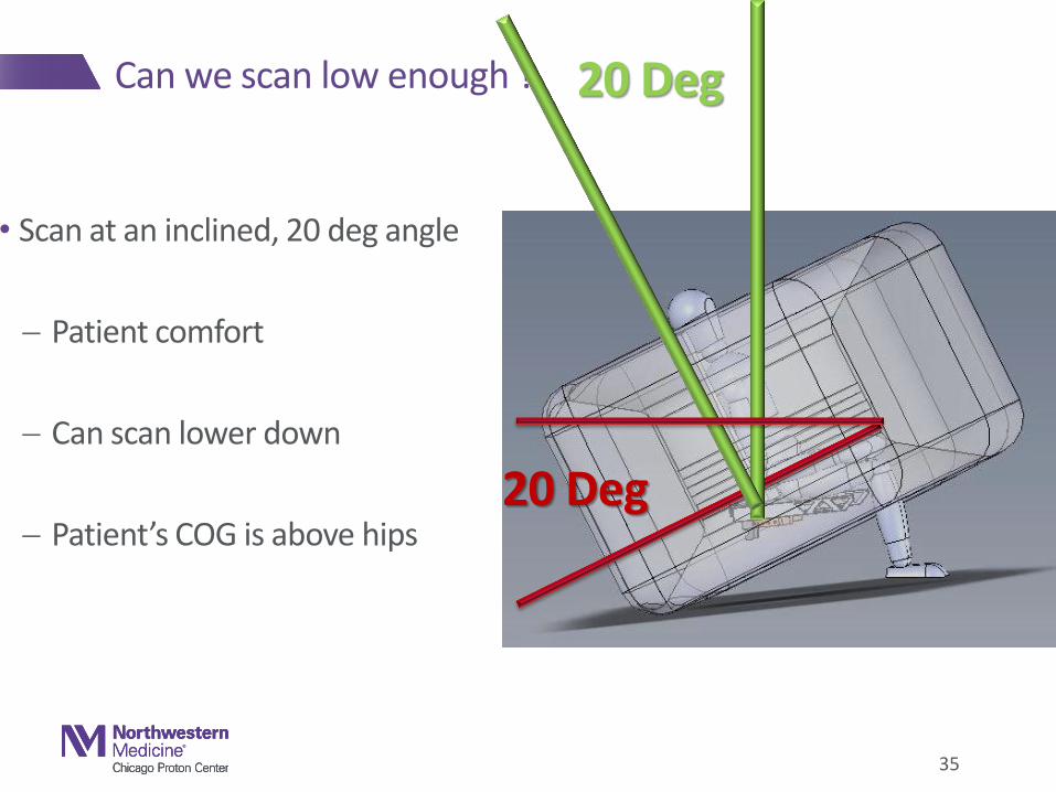
• Scan at an inclined, 20 deg angle
Patient comfort
Can scan lower down
Patient’s COG is above hips
35
Can we scan low enough ? 20 Deg
20 Deg
Beach Chair concept
36
• Interchangeable Backrests • Thorax • H&N patients
• May use a curved backrest • Allow for a better thoracic
immobilization shell • A need for arm supports
• Arms up or down
• A potential need for Chin / Head Straps

Beach Chair concept – comfort testing
37
Geometry testing in a Wooden chair at TDC

Horizontal CT : Additional Acceptance Testing
• Axial geometry accuracy • A geometric phantom with clearly identifiable objects of known separations will be imaged. Distances between objects
within an axial slice will be measured using the scanner software and compared to the know distances of the phantom. • Expected tolerance: The measured distance should not deviate from the known distance by more than one pixel length. • • Longitudinal geometry accuracy • A geometric phantom with clearly identifiable objects of known separations will be imaged. Distances between object
obtained on axial slices of differing longitudinal positions will be measured using the scanner software and compared to the know distances of the phantom.
• Expected tolerance: The measured distance should not deviate from the know distance by more than the axial slice thickness.
• • Orientation of the chair base with respect to the imaging plane • A series of images will be obtained of the treatment chair through a 30cm portion of the back support. • Expected tolerance: • On the axial image, the back of the chair should not deviate from the image plane in the Left/Right direction by more than
+/-1mm across the entire length of the treatment chair back. • On consecutive images, the back of the chair should not deviate in the anterior/posterior direction by more than +/- 1mm
over the entire length of the acquired images. • • Orientation of lasers with respect to the imaging plane • The CDH Proton Center’s CT laser phantom will be indexed to the treatment chair, aligned to the external lasers and
imaged. • Expected tolerance: Laser positions obtained from the phantom image shall coincide with the expected position on the
image by +/-2mm

Geometry Phantom for Horizontal Plane Scanner
39
Implementation plan
1) Use for treatment planning CT only
Respiratory monitoring?
2) On treatment CT in treatment position
3) Volumetric Localization
40
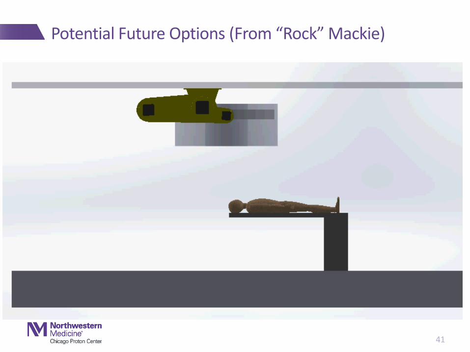
Potential Future Options (From “Rock” Mackie)
41

Thanks for your attention !!!
•Comments / Questions
•Are you interested???
•We are welcoming potential collaborators!
•Contact me at
42