Embed Size (px)
Citation preview
Shock and Vibration 15 (2008) 543–550 543IOS Press
Horizontal bulk material pressure in silosubjected to impulsive load
Radosław Tatkoa,∗ and Sylwester KobielakbaThe Faculty of Environmental Engineering and Geodesy, Wroclaw University of Environmental and Life Sciences,pl. Grunwaldzki 24, 50-363 Wroclaw, PolandbInstitute of Building Engineering, Wroclaw University of Technology, Wybrzeze Wyspianskiego 27, 50-370Wroclaw, Poland
Received 2 February 2006
Revised April 2007
Abstract. This paper describes laboratory tests carried out in the steel flat-bottomed silo model filled with sand, subjected toexternal dynamic loads. The model was placed on a system of springs, which represent subsoil. The loads in the form ofhorizontal impulses were applied to the bottom plate of the silo. Horizontal pressure-time courses were used to analyze theinfluence of subsoil vibrations on the distribution changes of these pressures. Basic conclusion: (1) the subsoil vibrations causetwo types of changes of the horizontal pressures: stable changes which are observed when the model vibrations finish and cyclicof short duration (brief) changes; (2) the subsoil vibrations either generate stable increase or stable decrease of the pressuresfrom before vibrations or do not generate any essential stable change; (3) the cyclic dynamic changes of the horizontal pressuresdepend on the direction of the silo wall displacements and they are the function of the values of these displacements.
Keywords: Silo model test, granular material, dynamic pressure measurement, vibration
1. Introduction
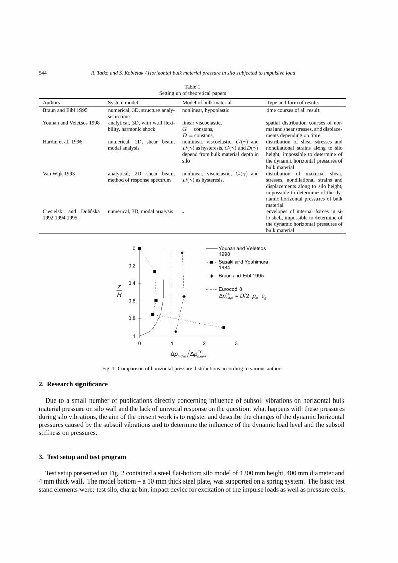
Not much has been known on the subject of behavior of silos and bulk materials stored into them subjected tosubsoil vibrations in despite of permanent interest of the anti-seismic engineering. Up to now only few papersreferring to this subject have been published. The most important theoretical papers are listed in Table 1. Well-established techniques were published by Braun and Eibl [1] and Younan and Veletsos [11,12]. In both theoreticalmodels which allow to determine the distribution of bulk material pressures acting on silo wall and stresses withinstored bulk material were presented. Papers about experimental tests on this subject are even fewer. Among thempapers of Sasaki and Yoshimura [9] and Sakai et al. [8] contain results in the form of dynamic pressure distributionsacting on the silo wall. Figure 1 shows discrepancies between the pressure distributions shown by above mentionedauthors. As can be seen from this Figure there exist large differences between individual data. One of the reasonscan be complicated nonlinear properties of bulk materials and mutual relations between their characteristics. Thebasic difficulty is to the formulate far-going assumptions concerning constitutive relations. They are necessary tosolve equations. Moreover, in the case of numerical model, entirely pure numerical constitutive parameters haveto be used. Constitutive parameters of the bulk materials have often decisive influence on the final result. Resultsof experimental tests which are carried out on the models of reduced scale models, generally are not possible totransferred on real objects due as scale effect. On the other hand test on real objects present technical-operating andoften financial difficulties.
∗Corresponding author. Tel.: +48 71 320 55 29; Fax: +48 71 320 55 84.
ISSN 1070-9622/08/$17.00 2008 – IOS Press and the authors. All rights reserved
544 R. Tatko and S. Kobielak / Horizontal bulk material pressure in silo subjected to impulsive load
Table 1Setting up of theoretical papers
Authors System model Model of bulk material Type and form of results
Braun and Eibl 1995 numerical, 3D, structure analy-sis in time
nonlinear, hypoplastic time courses of all result
Younan and Veletsos 1998 analytical, 3D, with wall flexi-bility, harmonic shock
linear viscoelastic,G = constans,D = constans,
spatial distribution courses of nor-mal and shear stresses, and displace-ments depending on time
Hardin et al. 1996 numerical, 2D, shear beam,modal analysis
nonlinear, viscoelastic,G(γ) andD(γ) as hysteresis,G(γ) andD(γ)depend from bulk material depth insilo
distribution of shear stresses andnondilational strains along to siloheight, impossible to determine ofthe dynamic horizontal pressures ofbulk material
Van Wijk 1993 analytical, 2D, shear beam,method of response spectrum
nonlinear, viscielastic,G(γ) andD(γ) as hysteresis,
distribution of maximal shear,stresses, nondilational strains anddisplacements along to silo height,impossible to determine of the dy-namic horizontal pressures of bulkmaterial
Ciesielski and Dulinska1992 1994 1995
numerical, 3D, modal analysis envelopes of internal forces in si-lo shell, impossible to determine ofthe dynamic horizontal pressures ofbulk material
D a
zH
∆ ∆, ,EC
h dyn h dynp p
0
0,2
0,4
0,6
0,8
1
0 1 2 3
Younan and Veletsos1998
Sasaki and Yoshimura1984
Braun and Eibl 1995
Eurocod 8ρ∆ =, 2EC
h dyn m gp . .
Fig. 1. Comparison of horizontal pressure distributions according to various authors.
2. Research significance
Due to a small number of publications directly concerning influence of subsoil vibrations on horizontal bulkmaterial pressure on silo wall and the lack of univocal response on the question: what happens with these pressuresduring silo vibrations, the aim of the present work is to register and describe the changes of the dynamic horizontalpressures caused by the subsoil vibrations and to determine the influence of the dynamic load level and the subsoilstiffness on pressures.
3. Test setup and test program
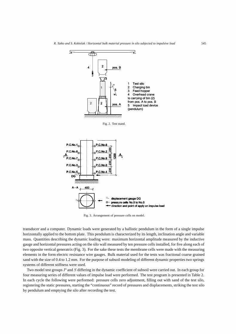
Test setup presented on Fig. 2 contained a steel flat-bottom silo model of 1200 mm height, 400 mm diameter and4 mm thick wall. The model bottom – a 10 mm thick steel plate, was supported on a spring system. The basic teststand elements were: test silo, charge bin, impact device for excitation of the impulse loads as well as pressure cells,
R. Tatko and S. Kobielak / Horizontal bulk material pressure in silo subjected to impulsive load 545
M
pos. B
pos. A2 2
2
15
4
3
1 Test silo2 Charging bin3 Feed hopper 4 Overhead crane to carrying of bin (2) from pos. A to pos. B5 Impact load device (pendulum)
M
pos. B
pos. A2 2
2
15
4
3
M
φ
pos. B
pos. A2 2
2
15
4
3
1 Test silo2 Charging bin3 Feed hopper 4 Overhead crane to carrying of bin (2) from pos. A to pos. B5 Impact load device (pendulum)
Fig. 2. Test stand.
displacement gauge DGpressure cells No.0 to No.9direction and point of apply an impulse load
A - A 400
A
235
235
235
235
1200
DG
P.C.No.1
P.C.No.8
P.C.No.7
P.C.No.3
P.C.No.5
P.C.No.0
P.C.No.6
P.C.No.2
P.C.No.9
P.C.No.4
A
displacement gauge DGpressure cells No.0 to No.9direction and point of apply an impulse load
displacement gauge DGpressure cells No.0 to No.9direction and point of apply an impulse load
displacement gauge DGpressure cells No.0 to No.9direction and point of apply an impulse load
A - A 400
A
235
235
235
235
1200
DG
P.C.No.1
P.C.No.8
P.C.No.7
P.C.No.3
P.C.No.5
P.C.No.0
P.C.No.6
P.C.No.2
P.C.No.9
P.C.No.4
A
A - A 400A - A 400
A
235
235
235
235
1200
DG
P.C.No.1
P.C.No.8
P.C.No.7
P.C.No.3
P.C.No.5
P.C.No.0
P.C.No.6
P.C.No.2
P.C.No.9
P.C.No.4
AA
235
235
235
235
1200
DG
P.C.No.1
P.C.No.8
P.C.No.7
P.C.No.3
P.C.No.5
DG
P.C.No.1
P.C.No.8
P.C.No.7
P.C.No.3
P.C.No.5
P.C.No.0
P.C.No.6
P.C.No.2
P.C.No.9
P.C.No.4
P.C.No.0
P.C.No.6
P.C.No.2
P.C.No.9
P.C.No.4
A
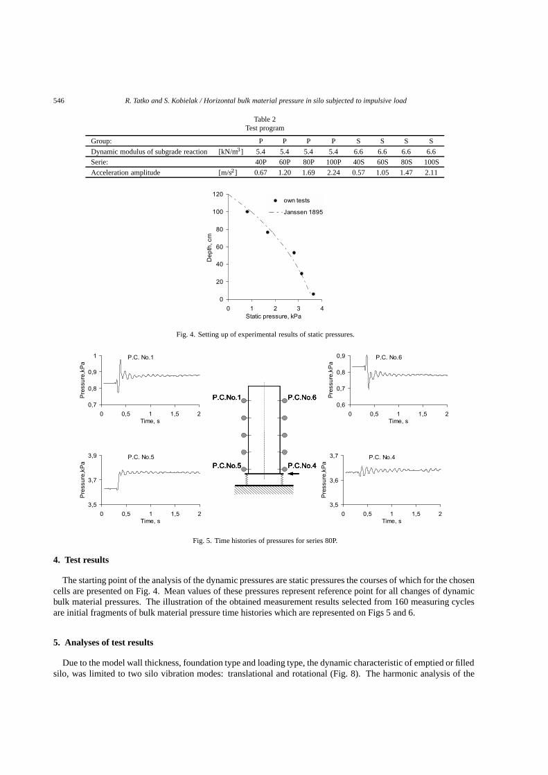
Fig. 3. Arrangement of pressure cells on model.
transducer and a computer. Dynamic loads were generated by a ballistic pendulum in the form of a single impulsehorizontally applied to the bottom plate. This pendulum is characterized by its length, inclination angle and variablemass. Quantities describing the dynamic loading were: maximum horizontal amplitude measured by the inductivegauge and horizontal pressures acting on the silo wall measured by ten pressure cells installed, for five along each oftwo opposite vertical generatrix (Fig. 3). For the sake these tests the membrane cells were made with the measuringelements in the form electric resistance wire gauges. Bulk material used for the tests was fractional coarse grainedsand with the size of 0.4 to 1.2 mm. For the purpose of subsoil modeling of different dynamic properties two springssystems of different stiffness were used.
Two model test groupsP andS differing in the dynamic coefficient of subsoil were carried out. In each group forfour measuring series of different values of impulse load were performed. The test program is presented in Table 2.In each cycle the following were performed: pressure cells zero adjustment, filling out with sand of the test silo,registering the static pressures, starting the “continuous” record of pressures and displacements, striking the test siloby pendulum and emptying the silo after recording the test.
546 R. Tatko and S. Kobielak / Horizontal bulk material pressure in silo subjected to impulsive load
Table 2Test program
Group: P P P P S S S S
Dynamic modulus of subgrade reaction [kN/m3] 5.4 5.4 5.4 5.4 6.6 6.6 6.6 6.6
Serie: 40P 60P 80P 100P 40S 60S 80S 100S
Acceleration amplitude [m/s2] 0.67 1.20 1.69 2.24 0.57 1.05 1.47 2.11
0
20
40
60
80
100
120
0 1 2 3 4Static pressure, kPa
Dep
th, c
mown tests
Janssen 1895
Fig. 4. Setting up of experimental results of static pressures.
P.C.No.1
P.C.No.5
P.C.No.6
P.C.No.4
P.C.No.1
P.C.No.5
P.C.No.1
P.C.No.5
P.C.No.6
P.C.No.4
P.C.No.6
P.C.No.4
P.C. No.1
0,7
0,8
0,9
1
0 0,5 1 1,5 2Time, s
Pre
ssur
e,kP
a
P.C. No.5
3,5
3,7
3,9
0 0,5 1 1,5 2Time, s
Pre
ssur
e,kP
a
P.C. No.4
3,5
3,6
3,7
0 0,5 1 1,5 2Time, s
Pre
ssur
e,kP
a
P.C. No.6
0,6
0,7
0,8
0,9
0 0,5 1 1,5 2Time, s
Pre
ssur
e,kP
a
Fig. 5. Time histories of pressures for series 80P.
4. Test results
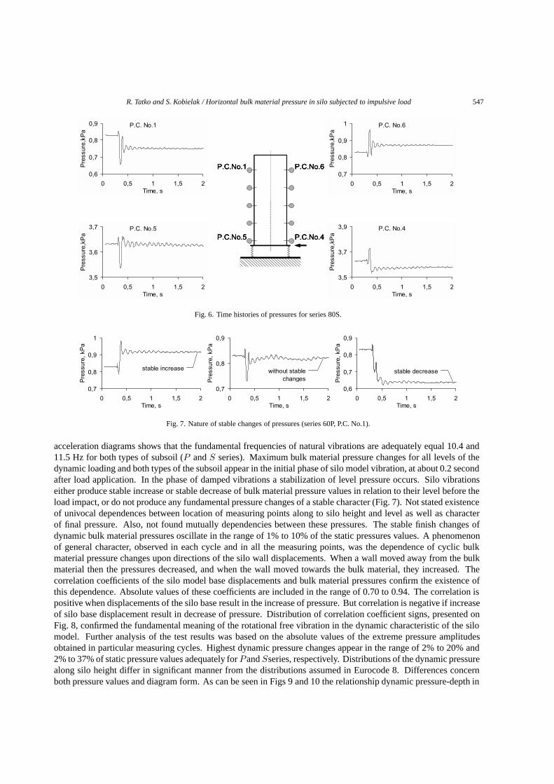
The starting point of the analysis of the dynamic pressures are static pressures the courses of which for the chosencells are presented on Fig. 4. Mean values of these pressures represent reference point for all changes of dynamicbulk material pressures. The illustration of the obtained measurement results selected from 160 measuring cyclesare initial fragments of bulk material pressure time histories which are represented on Figs 5 and 6.
5. Analyses of test results
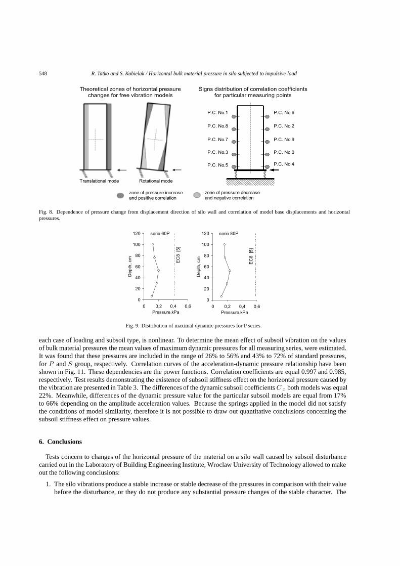
Due to the model wall thickness, foundation type and loading type, the dynamic characteristic of emptied or filledsilo, was limited to two silo vibration modes: translational and rotational (Fig. 8). The harmonic analysis of the
R. Tatko and S. Kobielak / Horizontal bulk material pressure in silo subjected to impulsive load 547
P.C.No.1
P.C.No.5
P.C.No.6
P.C.No.4
P.C.No.1
P.C.No.5
P.C.No.1
P.C.No.5
P.C.No.6
P.C.No.4
P.C.No.6
P.C.No.4
P.C. No.1
0,6
0,7
0,8
0,9
0 0,5 1 1,5 2Time, s
Pre
ssur
e,kP
a
P.C. No.6
0,7
0,8
0,9
1
0 0,5 1 1,5 2Time, s
Pre
ssur
e,kP
a
P.C. No.5
3,5
3,6
3,7
0 0,5 1 1,5 2Time, s
Pre
ssur
e,kP
a
P.C. No.4
3,5
3,7
3,9
0 0,5 1 1,5 2Time, s
Pre
ssur
e,kP
a
Fig. 6. Time histories of pressures for series 80S.
0,7
0,8
0,9
1
0 0,5 1 1,5 2Time, s
Pre
ssur
e, k
Pa
stable increase
0,7
0,8
0,9
0 0,5 1 1,5 2Time, s
Pre
ssur
e, k
Pa
without stable changes
0,6
0,7
0,8
0,9
0 0,5 1 1,5 2Time, s
Pre
ssur
e, k
Pa
stable decrease
Fig. 7. Nature of stable changes of pressures (series 60P, P.C. No.1).
acceleration diagrams shows that the fundamental frequencies of natural vibrations are adequately equal 10.4 and11.5 Hz for both types of subsoil (P andS series). Maximum bulk material pressure changes for all levels of thedynamic loading and both types of the subsoil appear in the initial phase of silo model vibration, at about 0.2 secondafter load application. In the phase of damped vibrations a stabilization of level pressure occurs. Silo vibrationseither produce stable increase or stable decrease of bulk material pressure values in relation to their level before theload impact, or do not produce any fundamental pressure changes of a stable character (Fig. 7). Not stated existenceof univocal dependences between location of measuring points along to silo height and level as well as characterof final pressure. Also, not found mutually dependencies between these pressures. The stable finish changes ofdynamic bulk material pressures oscillate in the range of 1% to 10% of the static pressures values. A phenomenonof general character, observed in each cycle and in all the measuring points, was the dependence of cyclic bulkmaterial pressure changes upon directions of the silo wall displacements. When a wall moved away from the bulkmaterial then the pressures decreased, and when the wall moved towards the bulk material, they increased. Thecorrelation coefficients of the silo model base displacements and bulk material pressures confirm the existence ofthis dependence. Absolute values of these coefficients are included in the range of 0.70 to 0.94. The correlation ispositive when displacements of the silo base result in the increase of pressure. But correlation is negative if increaseof silo base displacement result in decrease of pressure. Distribution of correlation coefficient signs, presented onFig. 8, confirmed the fundamental meaning of the rotational free vibration in the dynamic characteristic of the silomodel. Further analysis of the test results was based on the absolute values of the extreme pressure amplitudesobtained in particular measuring cycles. Highest dynamic pressure changes appear in the range of 2% to 20% and2% to 37% of static pressure values adequately forPandSseries, respectively. Distributions of the dynamic pressurealong silo height differ in significant manner from the distributions assumed in Eurocode 8. Differences concernboth pressure values and diagram form. As can be seen in Figs 9 and 10 the relationship dynamic pressure-depth in
548 R. Tatko and S. Kobielak / Horizontal bulk material pressure in silo subjected to impulsive load
Translational mode Rotational mode
P.C. No.1
P.C. No.0
P.C. No.8
P.C. No.7
P.C. No.3
P.C. No.5
P.C. No.6
P.C. No.2
P.C. No.9
P.C. No.4
Theoretical zones of horizontal pressurechanges for free vibration models
Signs distribution of correlation coefficientsfor particular measuring points
zone of pressure increase and positive correlation
zone of pressure decrease and negative correlation
Fig. 8. Dependence of pressure change from displacement direction of silo wall and correlation of model base displacements and horizontalpressures.
serie 60P
0
20
40
60
80
100
120
0 0,2 0,4 0,6Pressure,kPa
Dep
th, c
m
EC
8 [5
]
serie 80P
0
20
40
60
80
100
120
0 0,2 0,4 0,6Pressure,kPa
Dep
th, c
m
EC
8 [5
]
Fig. 9. Distribution of maximal dynamic pressures for P series.
each case of loading and subsoil type, is nonlinear. To determine the mean effect of subsoil vibration on the valuesof bulk material pressures the mean values of maximum dynamic pressures for all measuring series, were estimated.It was found that these pressures are included in the range of 26% to 56% and 43% to 72% of standard pressures,for P andS group, respectively. Correlation curves of the acceleration-dynamic pressure relationship have beenshown in Fig. 11. These dependencies are the power functions. Correlation coefficients are equal 0.997 and 0.985,respectively. Test results demonstrating the existence of subsoil stiffness effect on the horizontal pressure caused bythe vibration are presented in Table 3. The differences of the dynamic subsoil coefficientsC x both models was equal22%. Meanwhile, differences of the dynamic pressure value for the particular subsoil models are equal from 17%to 66% depending on the amplitude acceleration values. Because the springs applied in the model did not satisfythe conditions of model similarity, therefore it is not possible to draw out quantitative conclusions concerning thesubsoil stiffness effect on pressure values.
6. Conclusions
Tests concern to changes of the horizontal pressure of the material on a silo wall caused by subsoil disturbancecarried out in the Laboratory of Building Engineering Institute, Wroclaw University of Technology allowed to makeout the following conclusions:
1. The silo vibrations produce a stable increase or stable decrease of the pressures in comparison with their valuebefore the disturbance, or they do not produce any substantial pressure changes of the stable character. The
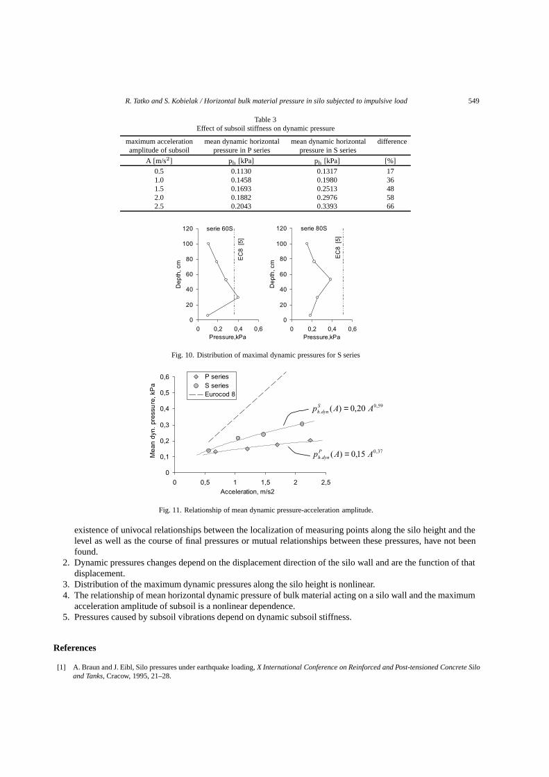
R. Tatko and S. Kobielak / Horizontal bulk material pressure in silo subjected to impulsive load 549
Table 3Effect of subsoil stiffness on dynamic pressure
maximum acceleration mean dynamic horizontal mean dynamic horizontal differenceamplitude of subsoil pressure in P series pressure in S series
A [m/s2] ph [kPa] ph [kPa] [%]
0.5 0.1130 0.1317 171.0 0.1458 0.1980 361.5 0.1693 0.2513 482.0 0.1882 0.2976 582.5 0.2043 0.3393 66
serie 60S
0
20
40
60
80
100
120
0 0,2 0,4 0,6Pressure,kPa
Dep
th, c
m
EC
8 [5
]
serie 80S
0
20
40
60
80
100
120
0 0,2 0,4 0,6Pressure,kPa
Dep
th, c
m
EC
8 [5
]
Fig. 10. Distribution of maximal dynamic pressures for S series
0
0,1
0,2
0,3
0,4
0,5
0,6
0 0,5 1 1,5 2 2,5Acceleration, m/s2
Mea
n dy
n. p
ress
ure
, kP
a
P seriesS seriesEurocod 8
37,0
. 15,0)( AApPdynh =
59,0
. 20,0)( AApSdynh =
Fig. 11. Relationship of mean dynamic pressure-acceleration amplitude.
existence of univocal relationships between the localization of measuring points along the silo height and thelevel as well as the course of final pressures or mutual relationships between these pressures, have not beenfound.
2. Dynamic pressures changes depend on the displacement direction of the silo wall and are the function of thatdisplacement.
3. Distribution of the maximum dynamic pressures along the silo height is nonlinear.4. The relationship of mean horizontal dynamic pressure of bulk material acting on a silo wall and the maximum
acceleration amplitude of subsoil is a nonlinear dependence.5. Pressures caused by subsoil vibrations depend on dynamic subsoil stiffness.
References
[1] A. Braun and J. Eibl, Silo pressures under earthquake loading,X International Conference on Reinforced and Post-tensioned Concrete Siloand Tanks, Cracow, 1995, 21–28.
550 R. Tatko and S. Kobielak / Horizontal bulk material pressure in silo subjected to impulsive load
[2] R. Ciesielski and J. Dulinska,Response analysis of cylindrical reinforced concrete silo under paraseismic disturbance, IX Conference onReinforced and Post-tensioned Concrete Silo and Tanks, Wrocław-Szklarska Pore¸ba, 13–35.
[3] R. Ciesielski and J. Dulinska,Analysis of paraseismic influences on selected structures of rotational-symmetrical types, VII Symposiumon Seismic and Paraseismic Influences on Structures, Cracow, 1994, 179–190.
[4] R. Ciesielski and J. Dulinska,Response comparison of rotational-symmetrical tanks on paraseismic influences for different disturbancemodes, X International Conference on Reinforced and Post-tensioned Concrete Silo and Tanks, Cracow, 1995, 13–20.
[5] Eurocode 8, Design Provision for Earthquake Resistance of Structures.[6] B.O. Hardin, R.A. Bucklin and I.J. Ross, Shear-beam analysis for seismic response of metal wheat bins,Transactions of the ASAE 39(2)
(1996), 677–687.[7] H.A. Janssen, Versucheuber Getreidedruck in Silozellen,Zeitschrift des Vereins deutscher Ingenieure 39(35) (1895), 1045–1049.[8] M. Sakai, H. Matsumura, M. Sasaki, N. Nakamura, M. Kobayashi and Y. Kitagawa, Study on the dynamic behavior of coal silos against
earthquakes,Bulk Solids Handling 5(5) (1985), 1021.[9] Y. Sasaki and J. Yoshimura,Dynamic behavior of concrete stave silos, Proceedings of the 8th World Conference on Earthquake Engineering,
1984.[10] L.A. Van Wijk, Earthquake resistance of mammoth silos of the Eurosilo type, PhD Thesis, University of Twente, Enschede, 1993.[11] A.H. Younan and A.S. Veletsos, Dynamics of solid-containing tanks, I: rigid tanks,Journal of Structural Engineering 124(1) (1998),
52–61.[12] A.H. Younan and A.S. Veletsos, Dynamics of solid-containing tanks, II: flexible tanks,Journal of Structural Engineering 124(1) (1998),
62–70.

International Journal of
AerospaceEngineeringHindawi Publishing Corporationhttp://www.hindawi.com Volume 2010
RoboticsJournal of
Hindawi Publishing Corporationhttp://www.hindawi.com Volume 2014
Hindawi Publishing Corporationhttp://www.hindawi.com Volume 2014
Active and Passive Electronic Components
Control Scienceand Engineering
Journal of
Hindawi Publishing Corporationhttp://www.hindawi.com Volume 2014
International Journal of
RotatingMachinery
Hindawi Publishing Corporationhttp://www.hindawi.com Volume 2014
Hindawi Publishing Corporation http://www.hindawi.com
Journal ofEngineeringVolume 2014
Submit your manuscripts athttp://www.hindawi.com
VLSI Design
Hindawi Publishing Corporationhttp://www.hindawi.com Volume 2014
Hindawi Publishing Corporationhttp://www.hindawi.com Volume 2014
Shock and Vibration
Hindawi Publishing Corporationhttp://www.hindawi.com Volume 2014
Civil EngineeringAdvances in
Acoustics and VibrationAdvances in
Hindawi Publishing Corporationhttp://www.hindawi.com Volume 2014
Hindawi Publishing Corporationhttp://www.hindawi.com Volume 2014
Electrical and Computer Engineering
Journal of
Advances inOptoElectronics
Hindawi Publishing Corporation http://www.hindawi.com
Volume 2014
The Scientific World JournalHindawi Publishing Corporation http://www.hindawi.com Volume 2014
SensorsJournal of
Hindawi Publishing Corporationhttp://www.hindawi.com Volume 2014
Modelling & Simulation in EngineeringHindawi Publishing Corporation http://www.hindawi.com Volume 2014
Hindawi Publishing Corporationhttp://www.hindawi.com Volume 2014
Chemical EngineeringInternational Journal of Antennas and
Propagation
International Journal of
Hindawi Publishing Corporationhttp://www.hindawi.com Volume 2014
Hindawi Publishing Corporationhttp://www.hindawi.com Volume 2014
Navigation and Observation
International Journal of
Hindawi Publishing Corporationhttp://www.hindawi.com Volume 2014
DistributedSensor Networks
International Journal of