Embed Size (px)
Citation preview
Horizontal Alignment and Design Speed
Horizontal Alignment and Design Speed
Norman W. GarrickLecture 11.2
Street and Highway Design
Norman W. GarrickLecture 11.2
Street and Highway Design
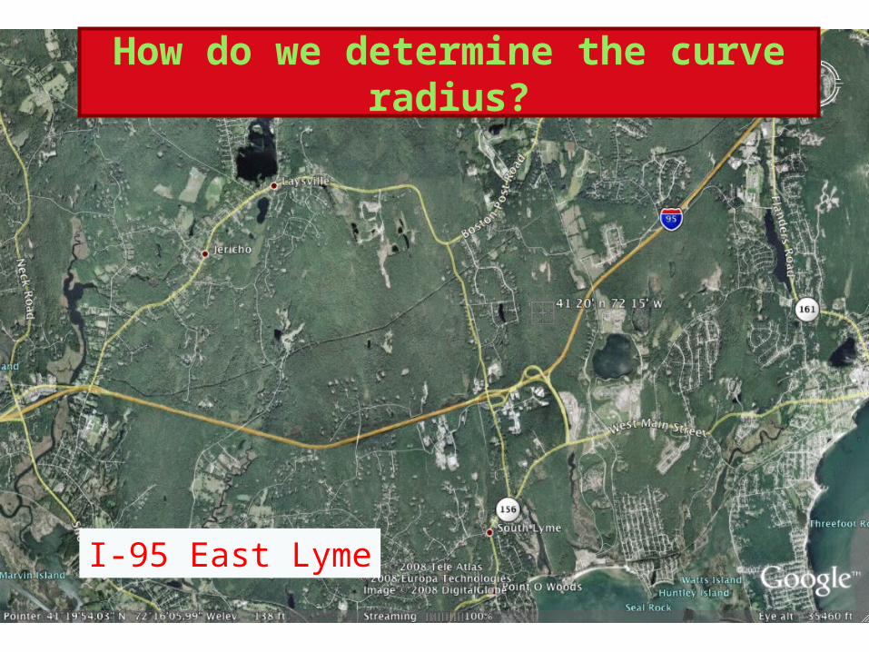
I-95 East Lyme
How do we determine the curve radius?
1000 ft
A
B
1
2
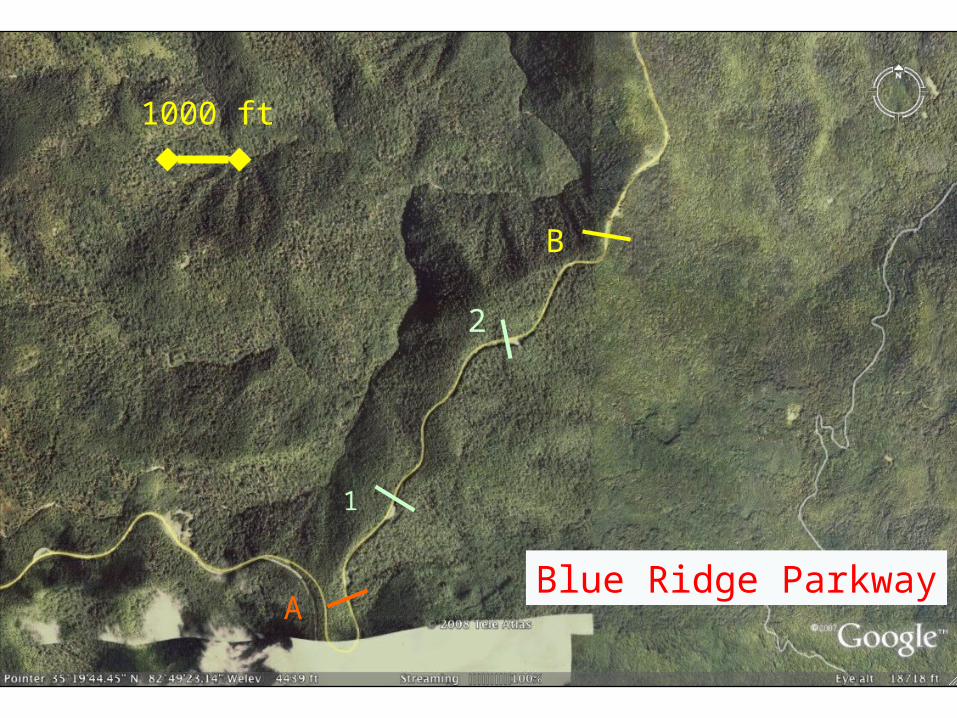
Blue Ridge Parkway

5000 ft
A
B
New York Thruway
5000 ft
A
B
1
2
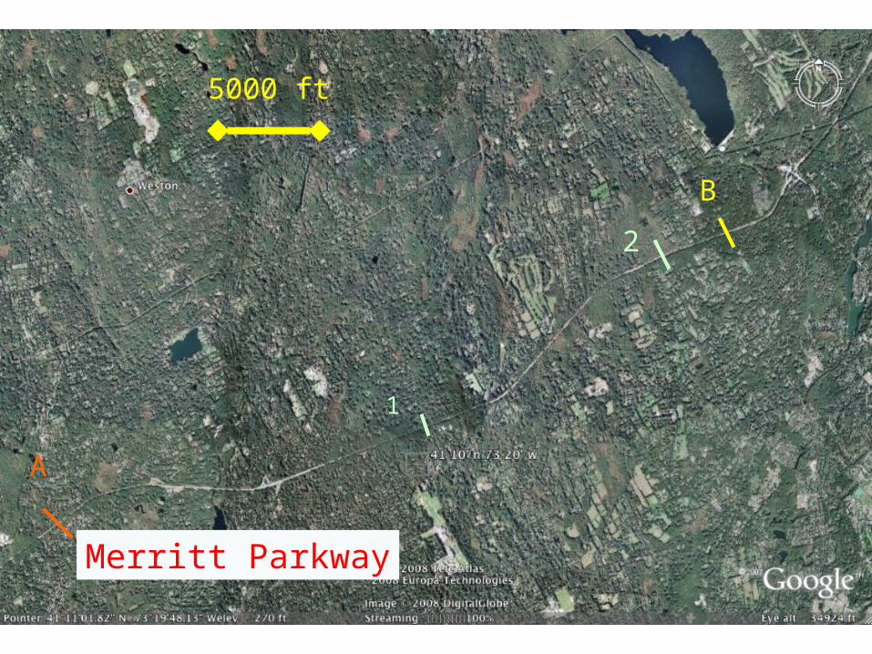
Merritt Parkway

http://www.bombardier.com/en/transportation/products-services/rail-vehicles/high-speed-trains/x2000---sweden?docID=0901260d80010605#
The first high-speed tilting train, X 2000, was delivered to Swedish State Railways in 1990 on the Stockholm - Gothenburg
route.
Travel time for this route was reduced by more than 25 percent with only minor
upgrading of the infrastructure.
The key to increased speeds lie in the radial self-steering bogies whereby track
forces are reduced, allowing up to 50 percent higher speed through curves.
Microprocessor-controlled, active passenger car tilting technology assures
passenger comfort in curves.
Swede High Speed Tilt Train

Norman W. Garrick
Cornering ForcesSoft Bogies!
Radial-steered bogies on their own allow an increase in operating speeds by 40% or up to 180Km/h (112mph) without increasing rail/wheel forces compared with conventional bogies.
This reduces wear on both the rail and wheels - wheel life is increased by up to six times. However, the increase in speeds allowed by these bogies would be uncomfortable to the passengers without tilt.
www.lococarriage.org.uk/x2000.htm
Norman W. Garrick
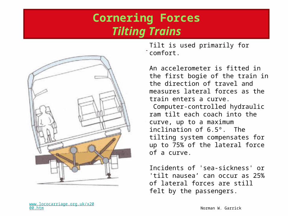
Tilt is used primarily for comfort.
An accelerometer is fitted in the first bogie of the train in the direction of travel and measures lateral forces as the train enters a curve. Computer-controlled hydraulic ram tilt each coach into the curve, up to a maximum inclination of 6.5º. The tilting system compensates for up to 75% of the lateral force of a curve. Incidents of 'sea-sickness' or 'tilt nausea’ can occur as 25% of lateral forces are still felt by the passengers.
www.lococarriage.org.uk/x2000.htm
Cornering ForcesTilting Trains

http://paultan.org/2006/01/11/top-gear-tests-cornering-ability/
Cornering Cars
Does you every day car need to handle like the EXIGE?

Forces on Cornering Car

mv2/rma
http://www.nascar.com/kyn/101/glossary/index.html
=Normal Forcemg


Road Superelevation (e)
What is largest superelevation rate practical?
Depends on Climate, Speed, Vehicle Type
Maximum superelevation in practice – 12%

Rate of superelevation is ‘e’ in %
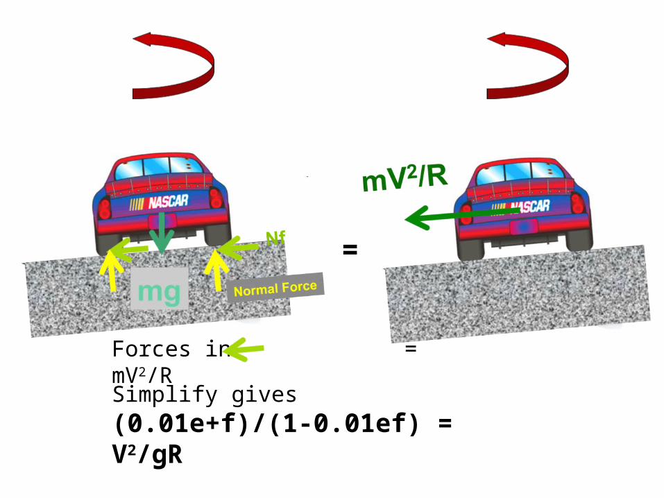
=
Forces in = mV2/R
Simplify gives (0.01e+f)/(1-0.01ef) = V2/gR
note: f is in fraction, e is in %

What Value of f should be used?
The road is designed so that the expected value of side friction is much less than the value that would cause sliding.
The value of ‘f’ used is equivalent to that which wouldcause a minimum level of discomfort to the vehicle occupants.

Maximum and Assume Side Friction
Norman W. Garrick
Maximum side friction for smooth tires and wet concrete – 0.35 at 45 mph
The value decrease as speed increase
The assumed value of side friction for design varies from 0.1 to 0.25 dependingon the design speed (higher values for lower speeds)
AASHTO
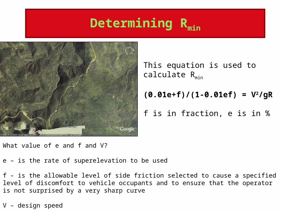
Determining Rmin
This equation is used to calculate Rmin
(0.01e+f)/(1-0.01ef) = V2/gR
f is in fraction, e is in %
What value of e and f and V?
e – is the rate of superelevation to be used
f – is the allowable level of side friction selected to cause a specified level of discomfort to vehicle occupants and to ensure that the operator is not surprised by a very sharp curve
V – design speed
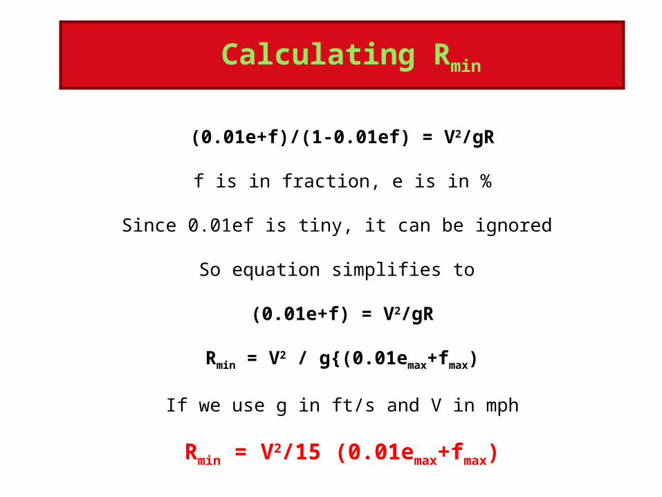
Calculating Rmin
(0.01e+f)/(1-0.01ef) = V2/gR
f is in fraction, e is in %
Since 0.01ef is tiny, it can be ignored
So equation simplifies to
(0.01e+f) = V2/gR
Rmin = V2 / g{(0.01emax+fmax)
If we use g in ft/s and V in mph
Rmin = V2/15 (0.01emax+fmax)

I-95: Calculating Rmin
Rmin = V2/15 (0.01emax+fmax)
I-95 East LymeAssumeV = Design Speed = 60 mphemax = 6 %fmax = 0.13
Rmin = 602 / 15 (0.01*6 + 0.13) = 3600/15*(0.19) = 1264 feet

I-95 East Lyme
R versus Rmin
R1 > Rmin
R2 > Rmin
R3 > Rmin
R4 > Rmin
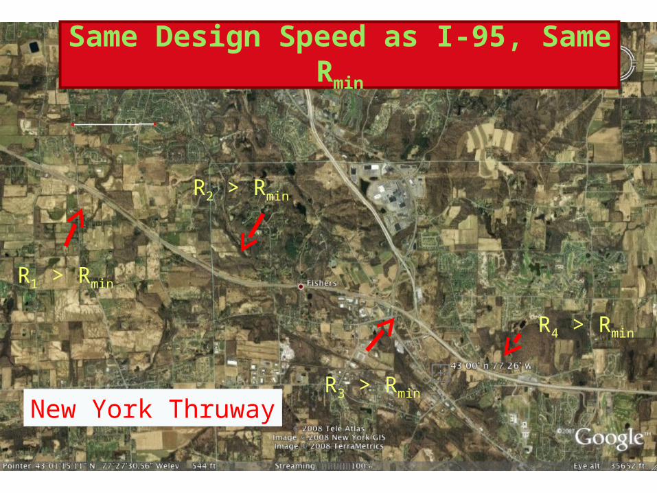
New York Thruway
Same Design Speed as I-95, Same Rmin
R1 > Rmin
R2 > Rmin
R3 > Rmin
R4 > Rmin
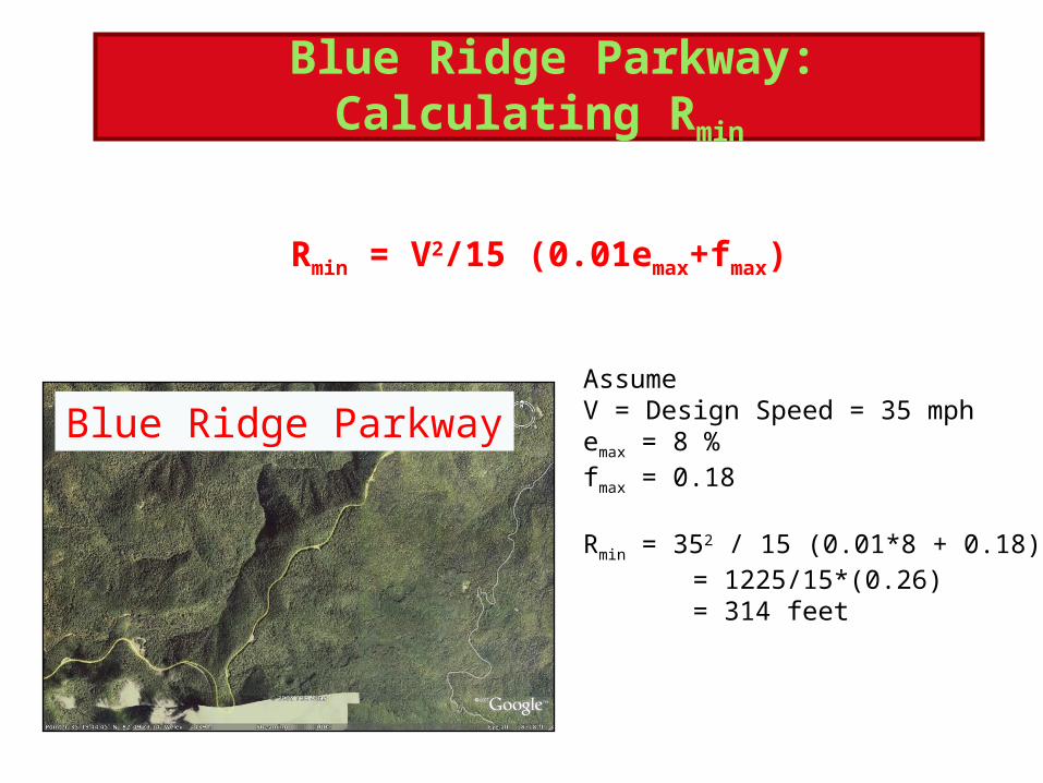
Blue Ridge Parkway: Calculating Rmin
Rmin = V2/15 (0.01emax+fmax)
Blue Ridge ParkwayAssumeV = Design Speed = 35 mphemax = 8 %fmax = 0.18
Rmin = 352 / 15 (0.01*8 + 0.18) = 1225/15*(0.26) = 314 feet