Embed Size (px)
Citation preview
1
HooToo Dual Band AC1200 Router
ONLINE GUIDE
Model: HT-ND001
2
Table of Contents
1 Product Overview .................................................................................... 4
1.1 Introduction ....................................................................................... 4
1.2 Package Contents ........................................................................... 5
1.3 Product Diagram .............................................................................. 6
1.4 LED Indicator ..................................................................................... 7
1.5 Physical Interface ............................................................................. 8
2 Connecting .............................................................................................. 9
2.1 Preparation ....................................................................................... 9
2.2 Hardware Connection .................................................................. 10
2.3 PC TCP/IP Settings .......................................................................... 10
2.4 For Windows .................................................................................... 11
2.5 For Mac OS ...................................................................................... 14
3. Logging into the Router ......................................................................... 15
3.1 Log in ................................................................................................ 15
3.2 Webpage Layout ........................................................................... 16
3.3 Commonly Used Webpage Elements ........................................ 17
4. Features & Configuration ...................................................................... 18
4.1 Quick Setup ..................................................................................... 18
4.1.1 Router ..................................................................................... 18
4.1.2 WISP ........................................................................................ 20
4.2 System Status................................................................................... 22
4.2.1 System Status ......................................................................... 23
4.2.2 WAN Status ............................................................................ 23
4.2.3 LAN Status .............................................................................. 25
4.2.4 Wireless Status ....................................................................... 25
4.3 Network Settings ............................................................................. 26
4.3.1 LAN Settings ........................................................................... 26
4.3.2 WAN Settings ......................................................................... 27
4.3.3 MAC Address Clone ............................................................. 31
4.4 WLAN Settings ................................................................................. 32
4.4.1 Basic Settings ......................................................................... 32
4.4.2 Security Settings .................................................................... 34
4.4.3 Advanced Settings ............................................................... 35
4.4.4 WPS Settings........................................................................... 36
4.4.5 Access Control ...................................................................... 36
4.4.6 Connection Status ................................................................ 37
4.5 USB Settings ..................................................................................... 37
3
4.5.1 Device Sharing ...................................................................... 37
4.5.2 Media Server ......................................................................... 43
4.5.3 Print Server ............................................................................. 43
4.5.4 User Account ......................................................................... 44
4.6 DHCP Server .................................................................................... 44
4.6.1 DHCP Server .......................................................................... 44
4.6.2 DHCP List & Binding .............................................................. 45
4.7 Virtual Server ................................................................................... 46
4.7.1 Port Range ............................................................................. 46
4.7.2 DMZ Settings .......................................................................... 48
4.7.3 UPnP Settings ......................................................................... 48
4.8 Security Settings .............................................................................. 49
4.8.1 Client Filter ............................................................................. 49
4.8.2 URL Filter ................................................................................. 52
4.8.3 MAC Filter ............................................................................... 54
4.8.4 Threat Prevention.................................................................. 57
4.8.5 Remote WEB Access ............................................................ 57
4.8.6 WAN Ping ............................................................................... 59
4.9 Routing Settings .............................................................................. 60
4.10 Traffic Control .................................................................................. 60
4.11 System Tools .................................................................................... 61
4.11.1 Time Settings ........................................................................ 61
4.11.2 DDNS ..................................................................................... 61
4.11.3 Backup/Restore .................................................................. 62
4.11.4 Factory Reset ....................................................................... 65
4.11.5 Firmware Upgrade .............................................................. 66
4.11.6 Reboot .................................................................................. 67
4.11.7 Change Password .............................................................. 68
4.11.8 System Log ........................................................................... 69
5 FAQs ........................................................................................................... 70
6 Factory Default Settings ........................................................................... 71
4
1 Product Overview
Thank you for choosing the HooToo HT-ND001 Dual Band AC1200 Router.
Please read this manual carefully and keep it for future reference.
1.1 Introduction
The HT-ND001 Router supports both 2.4GHz and 5GHz wireless bands for
up to 1200Mbps of total available bandwidth, as well as DHCP, PPPoE,
and static IP Internet modes. Other features include Wireless Password
Setup, USB functionality to save/read data to/from a USB flash drive, and
the following:
Compliance with IEEE 802.11a/an/ac and 802.11b/g/n
USB 3.0 port for file sharing and use as a print server
WPA/WPA2, WPA-PSK/WPA2-PSK authentication, TKIP/AES
encryption security
Access control
Client filter, MAC filter, URL filter
Remote web management
DDNS, Port forwarding, DMZ host, UPNP
5
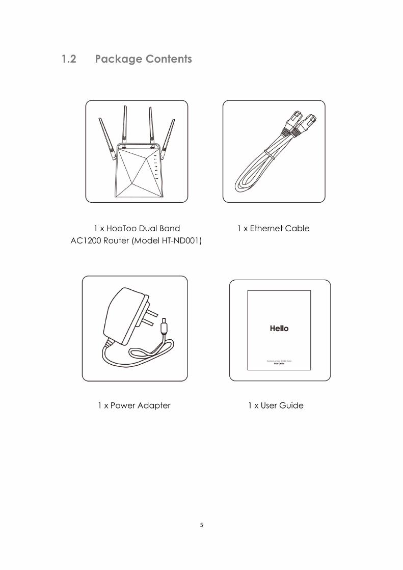
1.2 Package Contents
1 x HooToo Dual Band 1 x Ethernet Cable
AC1200 Router (Model HT-ND001)
1 x Power Adapter 1 x User Guide
6
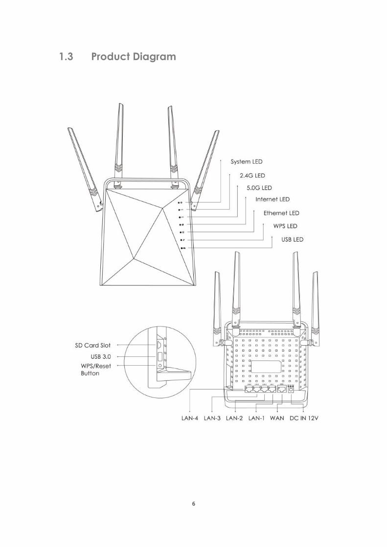
1.3 Product Diagram
7
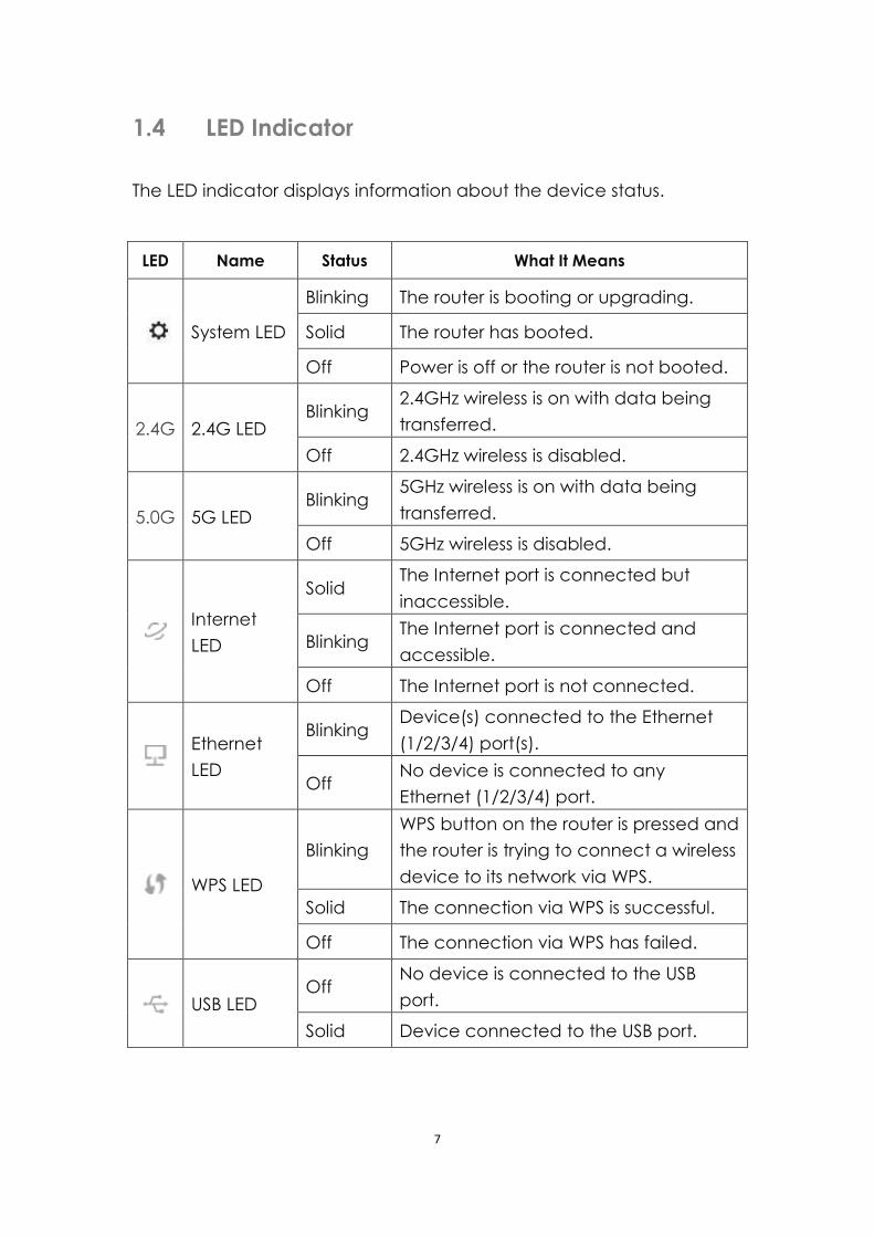
1.4 LED Indicator
The LED indicator displays information about the device status.
LED Name Status What It Means
System LED
Blinking The router is booting or upgrading.
Solid The router has booted.
Off Power is off or the router is not booted.
2.4G 2.4G LED Blinking
2.4GHz wireless is on with data being
transferred.
Off 2.4GHz wireless is disabled.
5.0G 5G LED Blinking
5GHz wireless is on with data being
transferred.
Off 5GHz wireless is disabled.
Internet
LED
Solid The Internet port is connected but
inaccessible.
Blinking The Internet port is connected and
accessible.
Off The Internet port is not connected.
Ethernet
LED
Blinking Device(s) connected to the Ethernet
(1/2/3/4) port(s).
Off No device is connected to any
Ethernet (1/2/3/4) port.
WPS LED
Blinking
WPS button on the router is pressed and
the router is trying to connect a wireless
device to its network via WPS.
Solid The connection via WPS is successful.
Off The connection via WPS has failed.
USB LED Off
No device is connected to the USB
port.
Solid Device connected to the USB port.
8
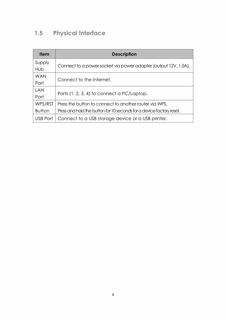
1.5 Physical Interface
Item Description
Supply
Hub Connect to a power socket via power adapter (output 12V, 1.5A).
WAN
Port Connect to the Internet.
LAN
Port Ports (1, 2, 3, 4) to connect a PC/Laptop.
WPS/RST
Button
Press the button to connect to another router via WPS.
Press and hold the button for 10 seconds for a device factory reset.
USB Port Connect to a USB storage device or a USB printer.
9
2 Connecting
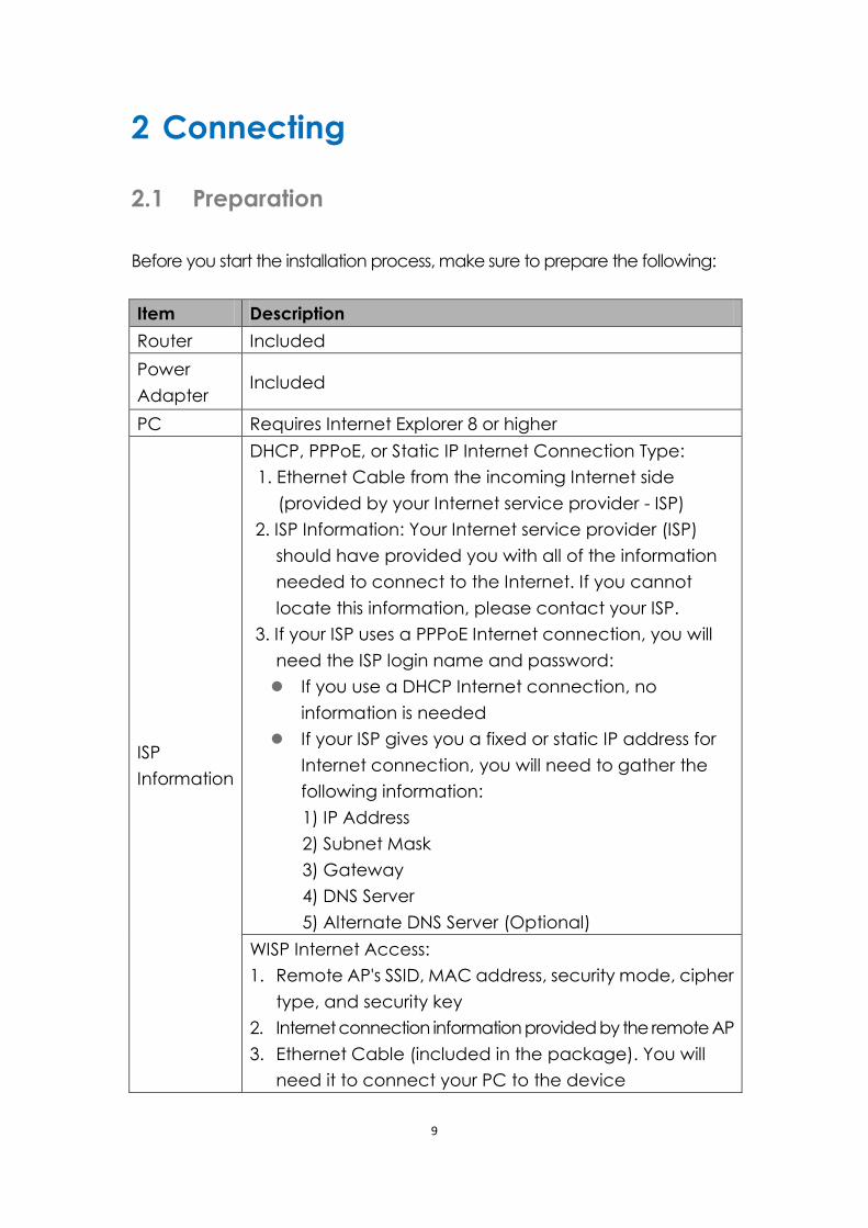
2.1 Preparation
Before you start the installation process, make sure to prepare the following:
Item Description
Router Included
Power
Adapter Included
PC Requires Internet Explorer 8 or higher
ISP
Information
DHCP, PPPoE, or Static IP Internet Connection Type:
1. Ethernet Cable from the incoming Internet side
(provided by your Internet service provider - ISP)
2. ISP Information: Your Internet service provider (ISP)
should have provided you with all of the information
needed to connect to the Internet. If you cannot
locate this information, please contact your ISP.
3. If your ISP uses a PPPoE Internet connection, you will
need the ISP login name and password:
If you use a DHCP Internet connection, no
information is needed
If your ISP gives you a fixed or static IP address for
Internet connection, you will need to gather the
following information:
1) IP Address
2) Subnet Mask
3) Gateway
4) DNS Server
5) Alternate DNS Server (Optional)
WISP Internet Access:
1. Remote AP's SSID, MAC address, security mode, cipher
type, and security key
2. Internet connection information provided by the remote AP
3. Ethernet Cable (included in the package). You will
need it to connect your PC to the device
10
2.2 Hardware Connection
Please follow the following steps to set up the router:
1. Use an Ethernet cable and connect the router's WAN port to the
internet.
2. Use an Ethernet cable and connect your computer’s Ethernet port
with the router’s LAN port.
3. Connect the router’s power adapter.
Note: Before connecting, please make sure that your internet is
working normally.
2.3 PC TCP/IP Settings
Prior to logging onto the router, please make sure your computer is set
to "Obtain an IP address automatically" and "Obtain DNS server
address automatically":
11
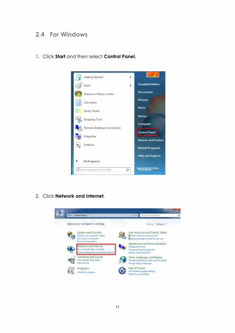
2.4 For Windows
1. Click Start and then select Control Panel.
2. Click Network and Internet.
12
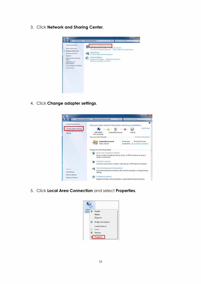
3. Click Network and Sharing Center.
4. Click Change adapter settings.
5. Click Local Area Connection and select Properties.
13
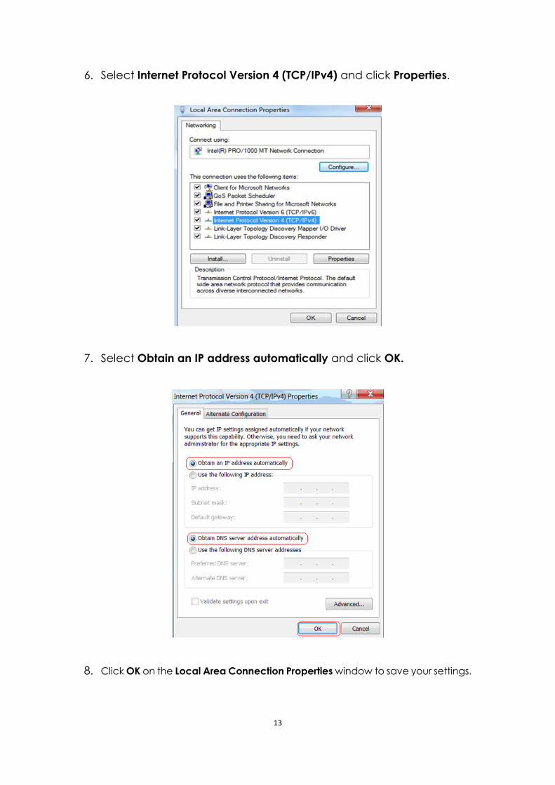
6. Select Internet Protocol Version 4 (TCP/IPv4) and click Properties.
7. Select Obtain an IP address automatically and click OK.
8. Click OK on the Local Area Connection Properties window to save your settings.
14
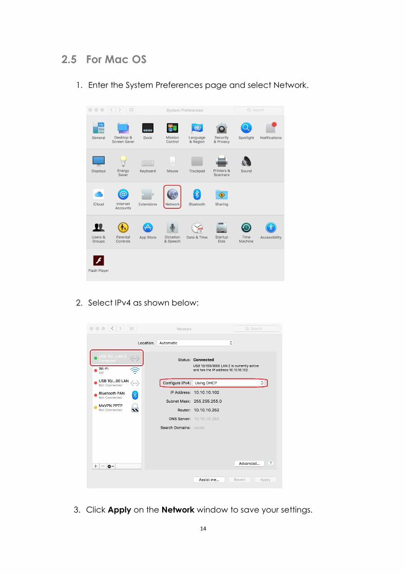
2.5 For Mac OS
1. Enter the System Preferences page and select Network.
2. Select IPv4 as shown below:
3. Click Apply on the Network window to save your settings.
15
3. Logging into the Router
3.1 Log in
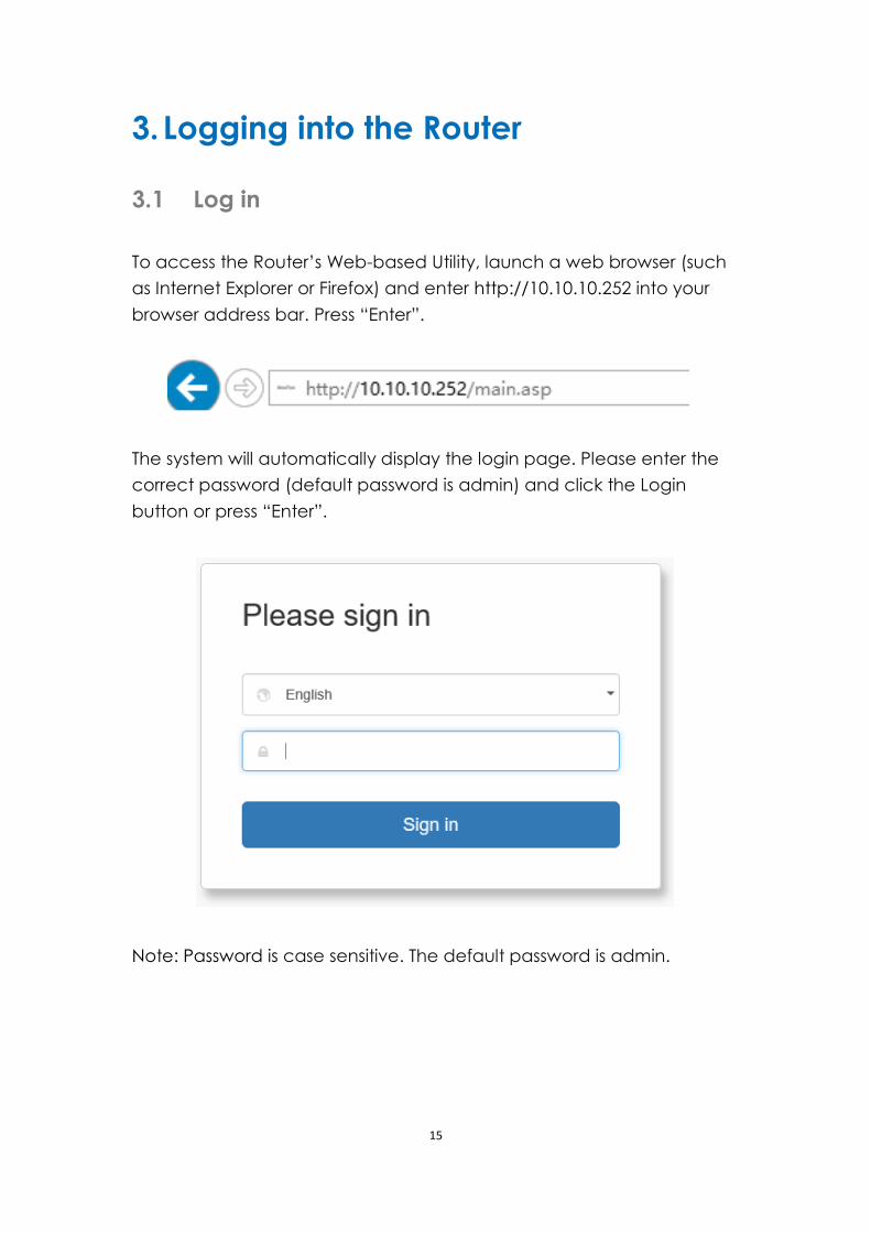
To access the Router’s Web-based Utility, launch a web browser (such
as Internet Explorer or Firefox) and enter http://10.10.10.252 into your
browser address bar. Press “Enter”.
The system will automatically display the login page. Please enter the
correct password (default password is admin) and click the Login
button or press “Enter”.
Note: Password is case sensitive. The default password is admin.
16
3.2 Webpage Layout
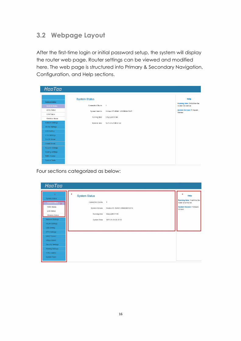
After the first-time login or initial password setup, the system will display
the router web page. Router settings can be viewed and modified
here. The web page is structured into Primary & Secondary Navigation,
Configuration, and Help sections.
Four sections categorized as below:
17
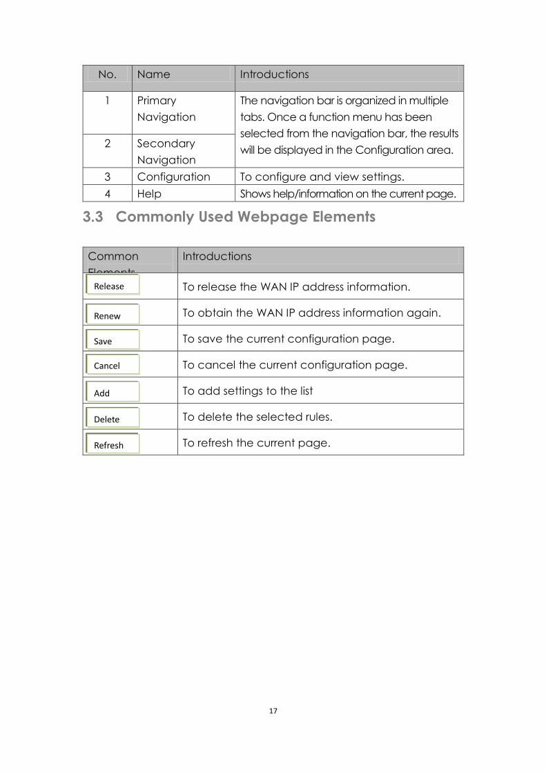
No. Name Introductions
1 Primary
Navigation
The navigation bar is organized in multiple
tabs. Once a function menu has been
selected from the navigation bar, the results
will be displayed in the Configuration area. 2 Secondary
Navigation
3 Configuration To configure and view settings.
4 Help Shows help/information on the current page.
3.3 Commonly Used Webpage Elements
Common
Elements
Introductions
To release the WAN IP address information.
To obtain the WAN IP address information again.
To save the current configuration page.
To cancel the current configuration page.
To add settings to the list
To delete the selected rules.
To refresh the current page.
Release
Renew
Save
Cancel
Add
Delete
Refresh
18
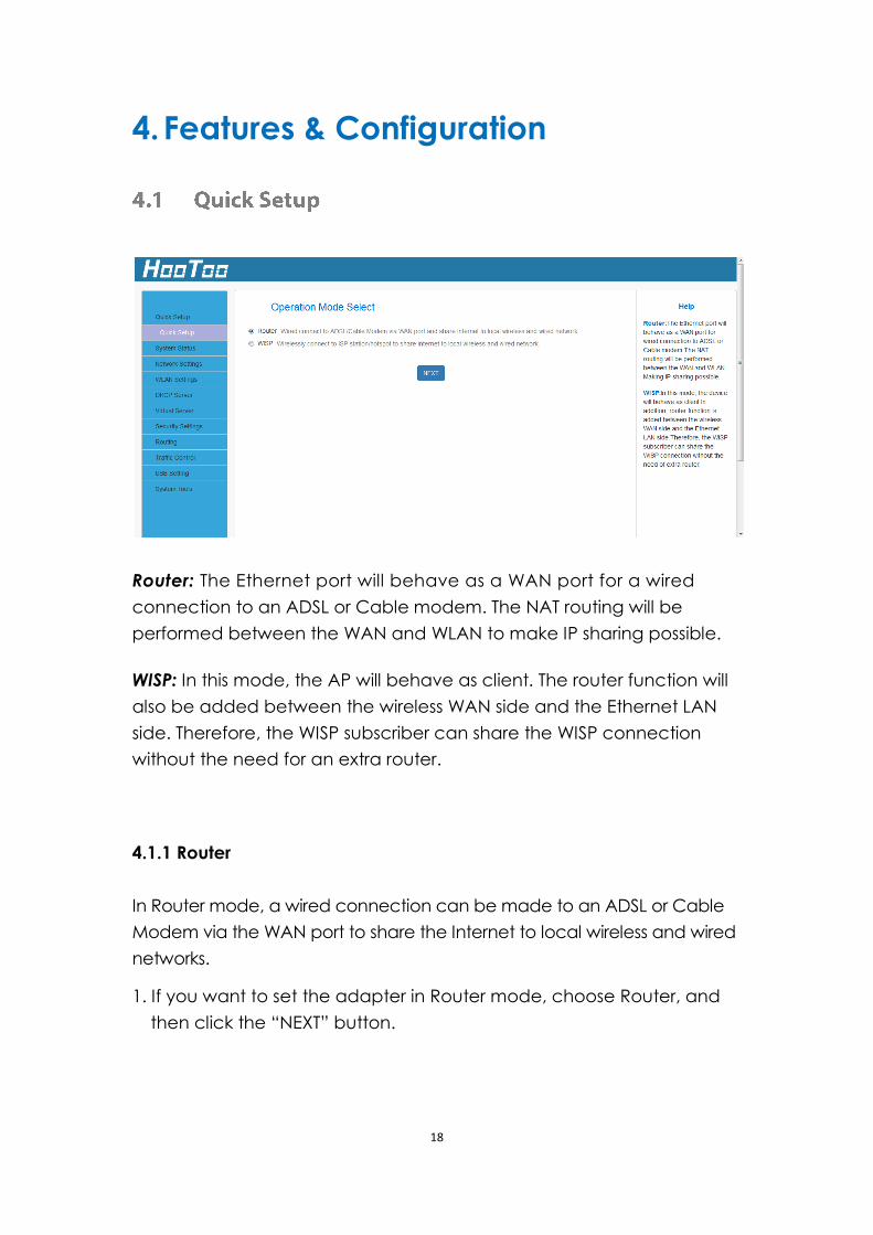
4. Features & Configuration
Router: The Ethernet port will behave as a WAN port for a wired
connection to an ADSL or Cable modem. The NAT routing will be
performed between the WAN and WLAN to make IP sharing possible.
WISP: In this mode, the AP will behave as client. The router function will
also be added between the wireless WAN side and the Ethernet LAN
side. Therefore, the WISP subscriber can share the WISP connection
without the need for an extra router.
4.1.1 Router
In Router mode, a wired connection can be made to an ADSL or Cable
Modem via the WAN port to share the Internet to local wireless and wired
networks.
1. If you want to set the adapter in Router mode, choose Router, and
then click the “NEXT” button.
19
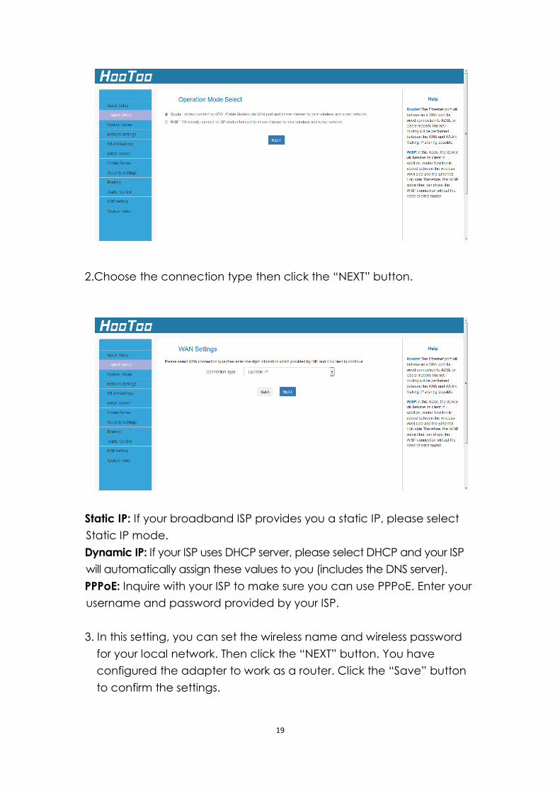
2.Choose the connection type then click the “NEXT” button.
Static IP: If your broadband ISP provides you a static IP, please select
Static IP mode.
Dynamic IP: If your ISP uses DHCP server, please select DHCP and your ISP
will automatically assign these values to you (includes the DNS server).
PPPoE: Inquire with your ISP to make sure you can use PPPoE. Enter your
username and password provided by your ISP.
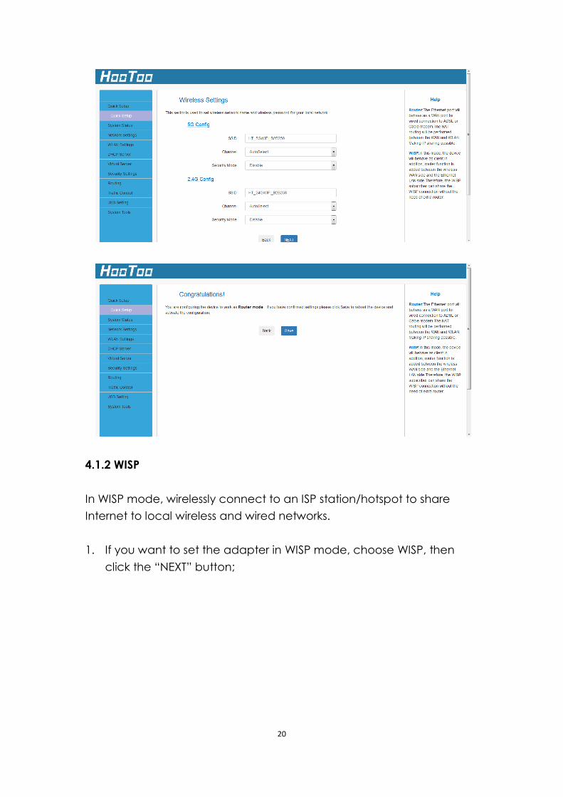
3. In this setting, you can set the wireless name and wireless password
for your local network. Then click the “NEXT” button. You have
configured the adapter to work as a router. Click the “Save” button
to confirm the settings.
20
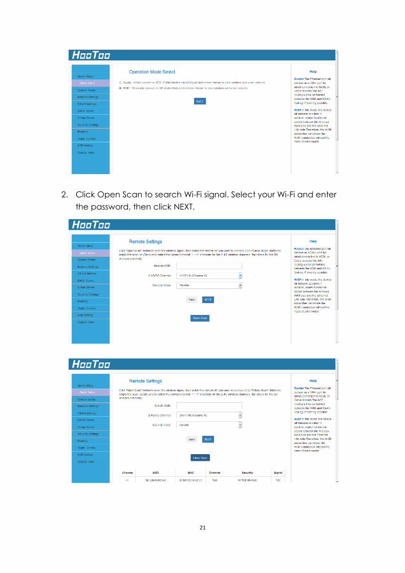
4.1.2 WISP
In WISP mode, wirelessly connect to an ISP station/hotspot to share
Internet to local wireless and wired networks.
1. If you want to set the adapter in WISP mode, choose WISP, then
click the “NEXT” button;
21
2. Click Open Scan to search Wi-Fi signal. Select your Wi-Fi and enter
the password, then click NEXT.
22
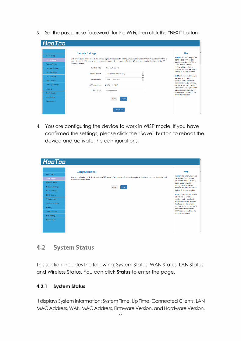
3. Set the pass phrase (password) for the Wi-Fi, then click the “NEXT” button.
4. You are configuring the device to work in WISP mode. If you have
confirmed the settings, please click the “Save” button to reboot the
device and activate the configurations.
This section includes the following: System Status, WAN Status, LAN Status,
and Wireless Status. You can click Status to enter the page.
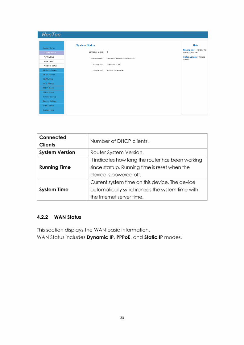
4.2.1 System Status
It displays System Information: System Time, Up Time, Connected Clients, LAN
MAC Address, WAN MAC Address, Firmware Version, and Hardware Version.
23
Connected
Clients Number of DHCP clients.
System Version Router System Version.
Running Time
It indicates how long the router has been working
since startup. Running time is reset when the
device is powered off.
System Time
Current system time on this device. The device
automatically synchronizes the system time with
the Internet server time.
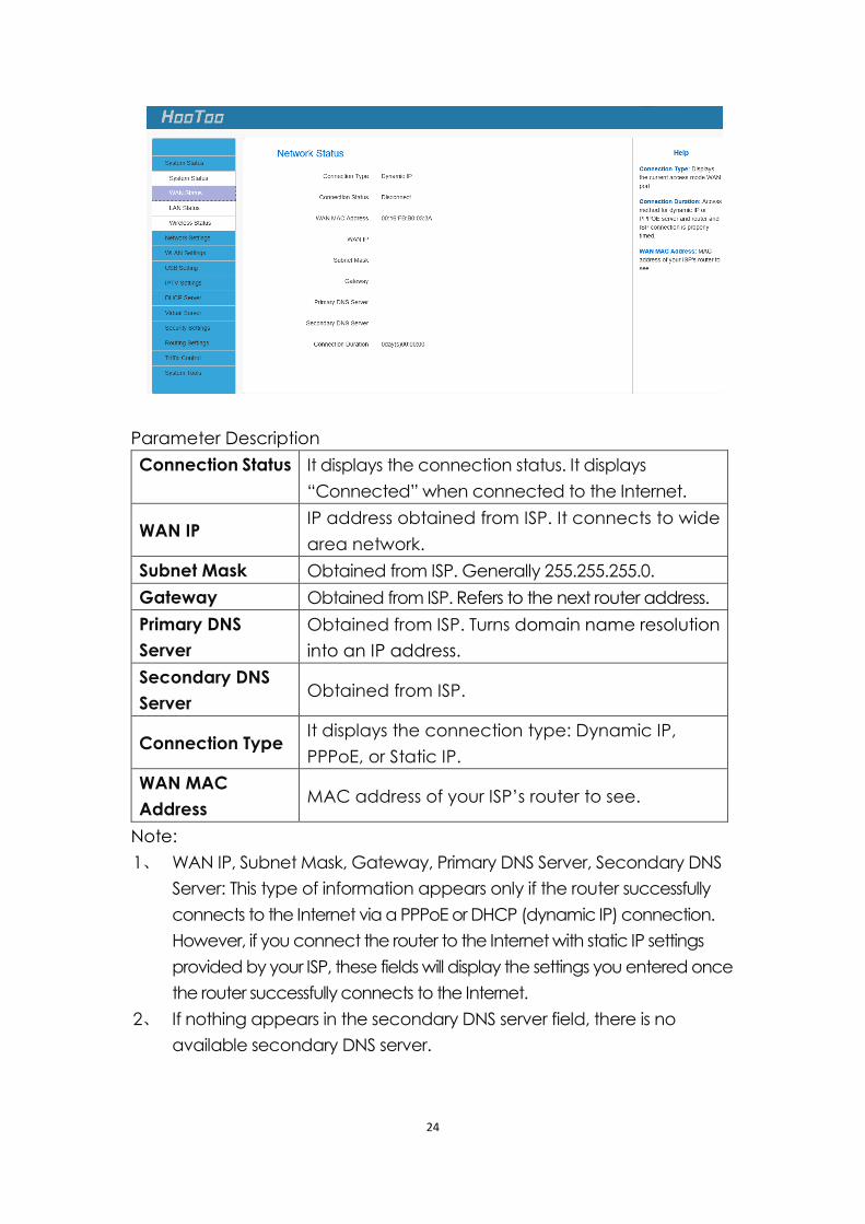
4.2.2 WAN Status
This section displays the WAN basic information.
WAN Status includes Dynamic IP, PPPoE, and Static IP modes.
24
Parameter Description
Connection Status It displays the connection status. It displays
“Connected” when connected to the Internet.
WAN IP IP address obtained from ISP. It connects to wide
area network.
Subnet Mask Obtained from ISP. Generally 255.255.255.0.
Gateway Obtained from ISP. Refers to the next router address.
Primary DNS
Server
Obtained from ISP. Turns domain name resolution
into an IP address.
Secondary DNS
Server Obtained from ISP.
Connection Type It displays the connection type: Dynamic IP,
PPPoE, or Static IP.
WAN MAC
Address MAC address of your ISP’s router to see.
Note:
1、 WAN IP, Subnet Mask, Gateway, Primary DNS Server, Secondary DNS
Server: This type of information appears only if the router successfully
connects to the Internet via a PPPoE or DHCP (dynamic IP) connection.
However, if you connect the router to the Internet with static IP settings
provided by your ISP, these fields will display the settings you entered once
the router successfully connects to the Internet.
2、 If nothing appears in the secondary DNS server field, there is no
available secondary DNS server.
25
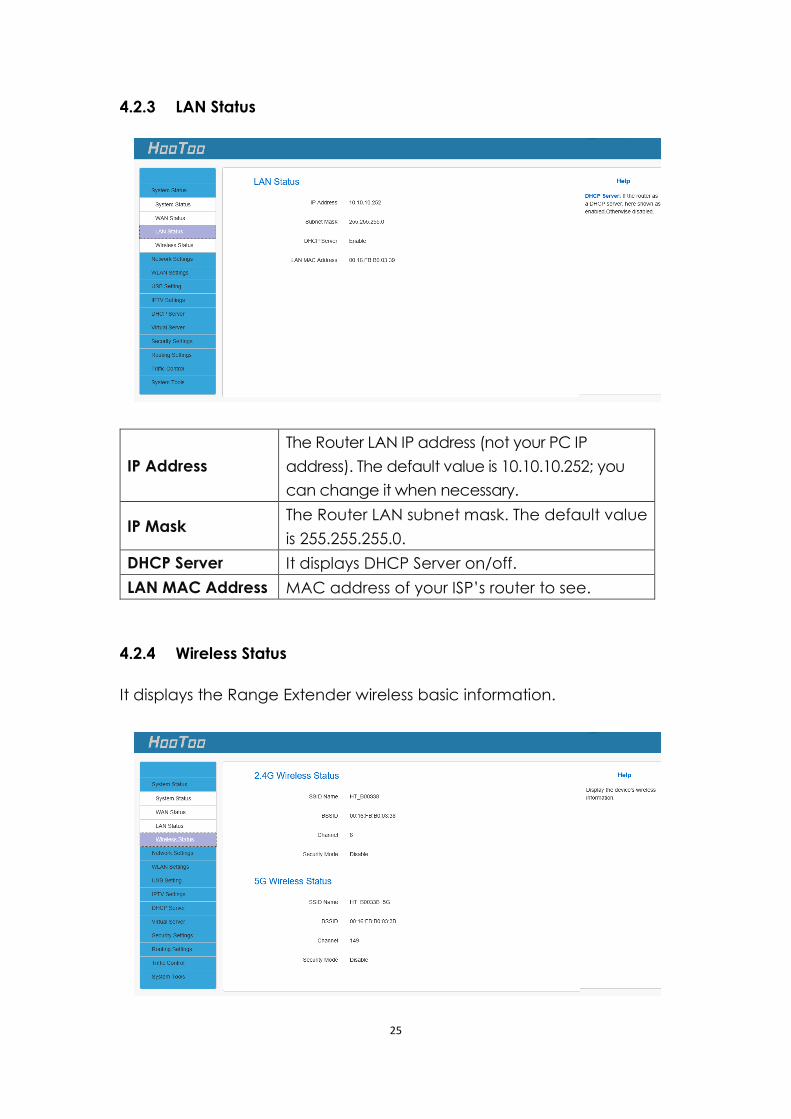
4.2.3 LAN Status
IP Address
The Router LAN IP address (not your PC IP
address). The default value is 10.10.10.252; you
can change it when necessary.
IP Mask The Router LAN subnet mask. The default value
is 255.255.255.0.
DHCP Server It displays DHCP Server on/off.
LAN MAC Address MAC address of your ISP’s router to see.
4.2.4 Wireless Status
It displays the Range Extender wireless basic information.
26
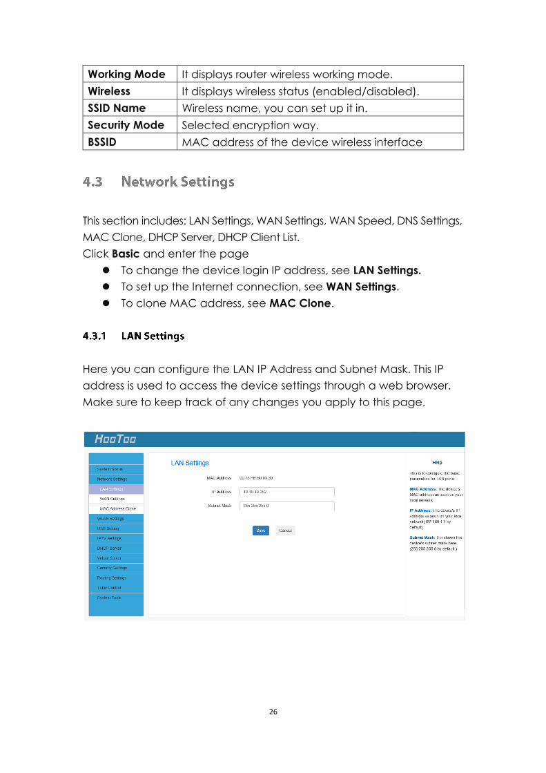
Working Mode It displays router wireless working mode.
Wireless It displays wireless status (enabled/disabled).
SSID Name Wireless name, you can set up it in.
Security Mode Selected encryption way.
BSSID MAC address of the device wireless interface
This section includes: LAN Settings, WAN Settings, WAN Speed, DNS Settings,
MAC Clone, DHCP Server, DHCP Client List.
Click Basic and enter the page
To change the device login IP address, see LAN Settings.
To set up the Internet connection, see WAN Settings.
To clone MAC address, see MAC Clone.
Here you can configure the LAN IP Address and Subnet Mask. This IP
address is used to access the device settings through a web browser.
Make sure to keep track of any changes you apply to this page.
27
Configuration Procedure:
1. Change the IP address to the one you wish to use, for example,
10.10.10.252.
2. Click Save to save your settings.
Note:
1. Default IP address and subnet mask are, respectively, 10.10.10.252
and 255.255.255.0.
2. Make sure to keep track of any changes you apply to this page. If
you change the Router LAN IP address, it is necessary to connect to
the new IP address and log in again. Also, you have to set the default
gateway addresses of all LAN PCs to this new IP address.
3. The router LAN IP address and WAN IP address cannot be on the same
IP segment. If not, the router will not be able to access the Internet.
4.3.2 WAN Settings
Here you can configure your Internet connection settings. First, select
internet connection type:
A. Select PPPoE if your ISP uses a PPPoE connection and gives you a
PPPoE user name and a PPPoE password.
B. Select Static IP if your ISP provides you with fixed or static IP address
settings (special deployment by ISP).
C. Select Dynamic IP if you can access Internet simply by directly
connecting your computer to an Internet-enabled ADSL/Cable
modem without configuring any settings.
Different connection types will have different a different configuration:
28
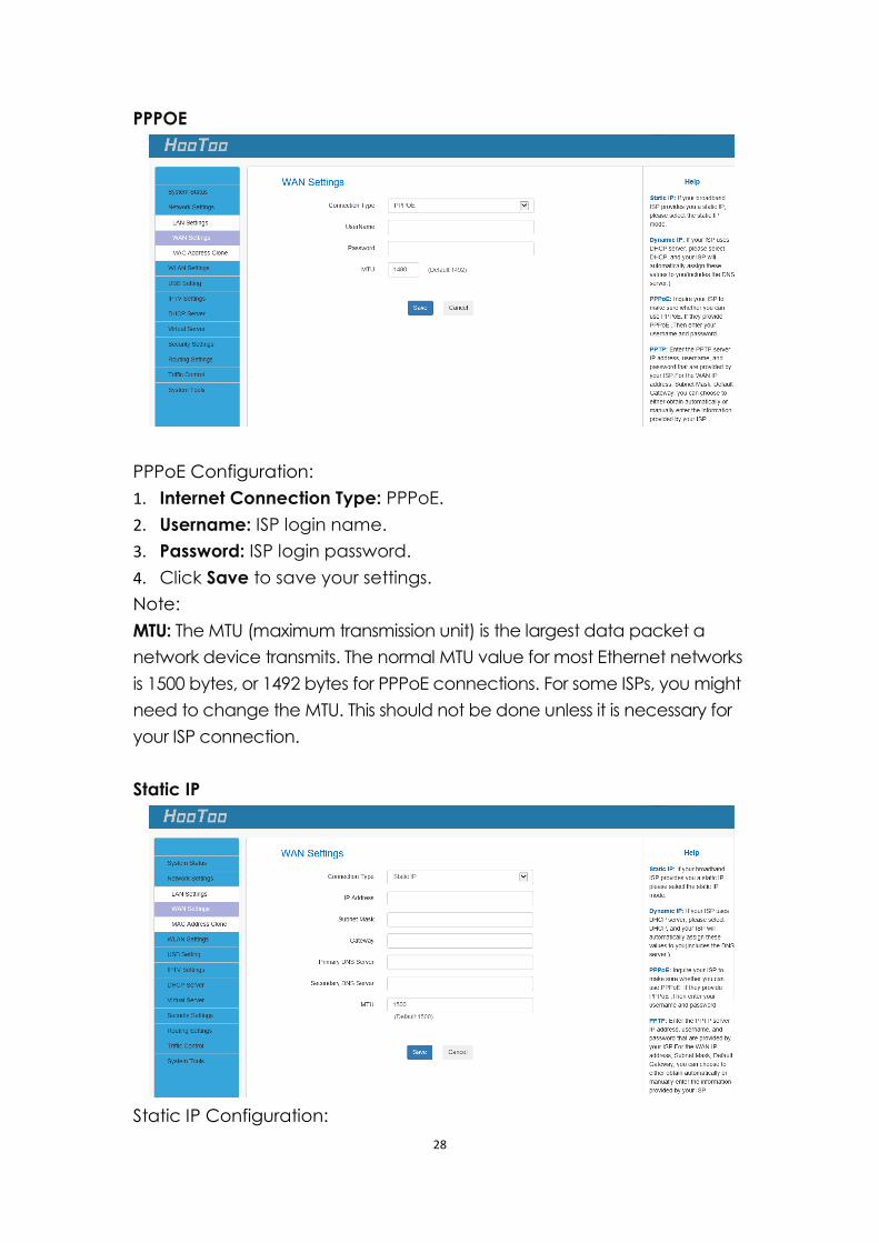
PPPOE
PPPoE Configuration:
1. Internet Connection Type: PPPoE.
2. Username: ISP login name.
3. Password: ISP login password.
4. Click Save to save your settings.
Note:
MTU: The MTU (maximum transmission unit) is the largest data packet a
network device transmits. The normal MTU value for most Ethernet networks
is 1500 bytes, or 1492 bytes for PPPoE connections. For some ISPs, you might
need to change the MTU. This should not be done unless it is necessary for
your ISP connection.
Static IP
Static IP Configuration:
29
1. Connection Type: Static IP.
2. IP Address/Subnet Mask/Gateway/Primary DNS Server/Secondary
DNS Server: ISP information.
3. Click Save to save your settings.
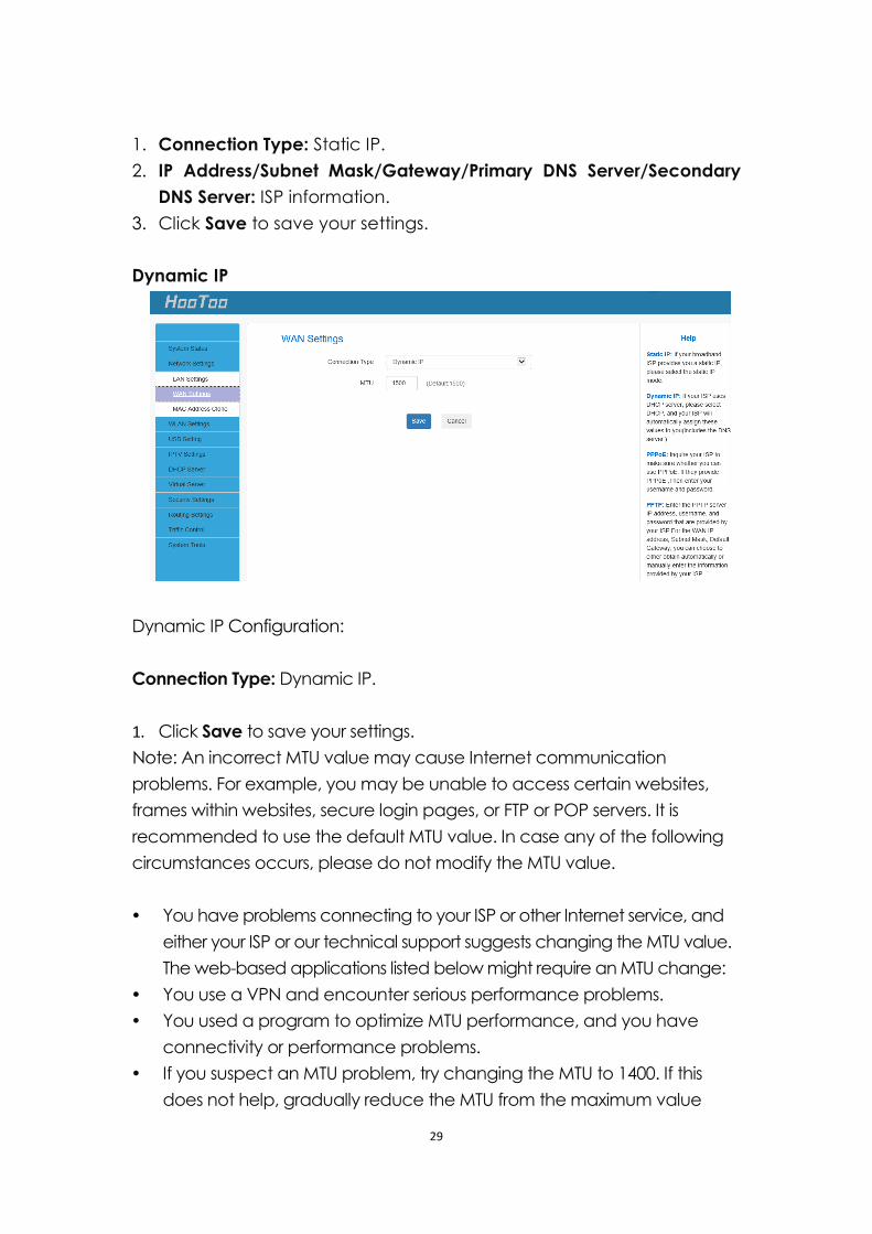
Dynamic IP
Dynamic IP Configuration:
Connection Type: Dynamic IP.
1. Click Save to save your settings.
Note: An incorrect MTU value may cause Internet communication
problems. For example, you may be unable to access certain websites,
frames within websites, secure login pages, or FTP or POP servers. It is
recommended to use the default MTU value. In case any of the following
circumstances occurs, please do not modify the MTU value.
You have problems connecting to your ISP or other Internet service, and
either your ISP or our technical support suggests changing the MTU value.
The web-based applications listed below might require an MTU change:
You use a VPN and encounter serious performance problems.
You used a program to optimize MTU performance, and you have
connectivity or performance problems.
If you suspect an MTU problem, try changing the MTU to 1400. If this
does not help, gradually reduce the MTU from the maximum value
30
1500 until the issue disappears.
The common MTU sizes and applications are listed in the table below.
MTU Application
1500 Typical for connections that do not use PPPoE or VPN.
1492 Used in PPPoE environments.
1472 Maximum size to use for pinging. (Larger packets are
fragmented.)
1468 Used in some DHCP environments.
1436 Used in PPTP environments or with VPN.
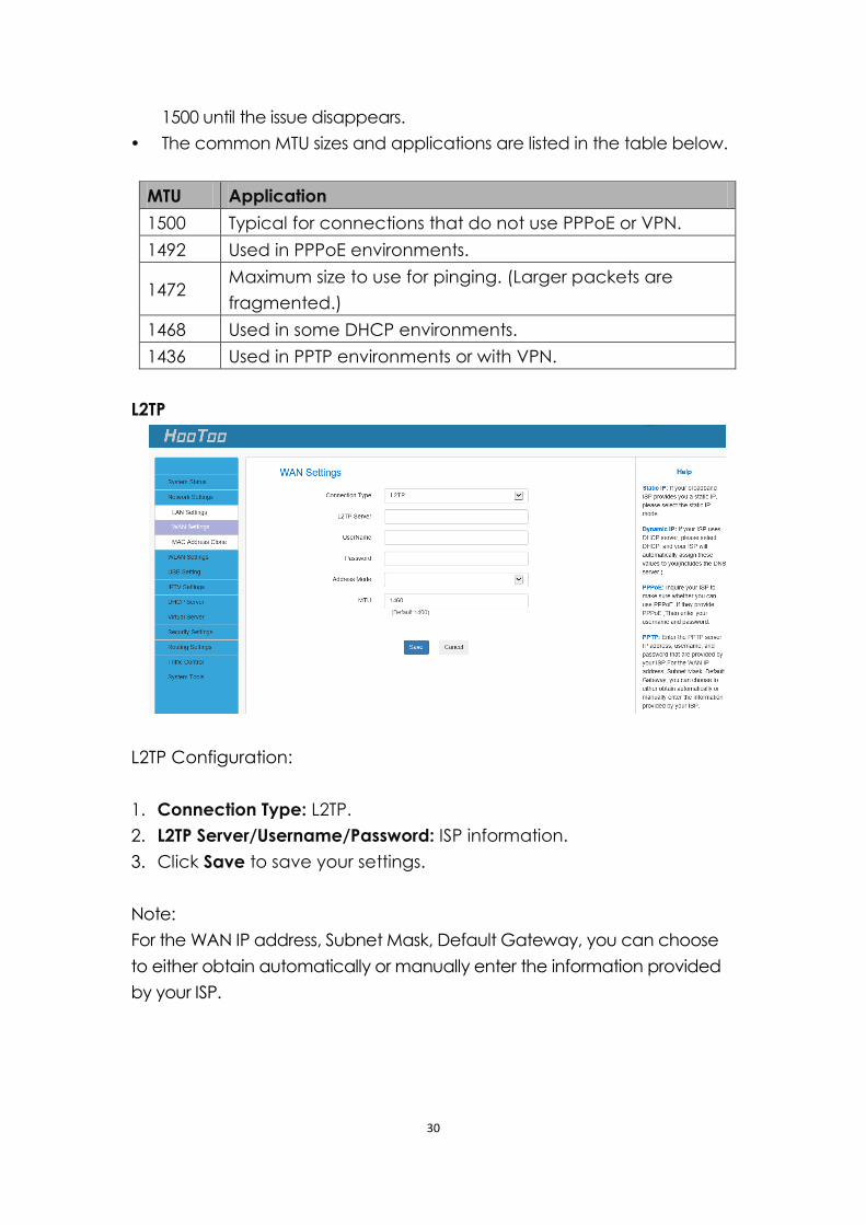
L2TP
L2TP Configuration:
1. Connection Type: L2TP.
2. L2TP Server/Username/Password: ISP information.
3. Click Save to save your settings.
Note:
For the WAN IP address, Subnet Mask, Default Gateway, you can choose
to either obtain automatically or manually enter the information provided
by your ISP.
31
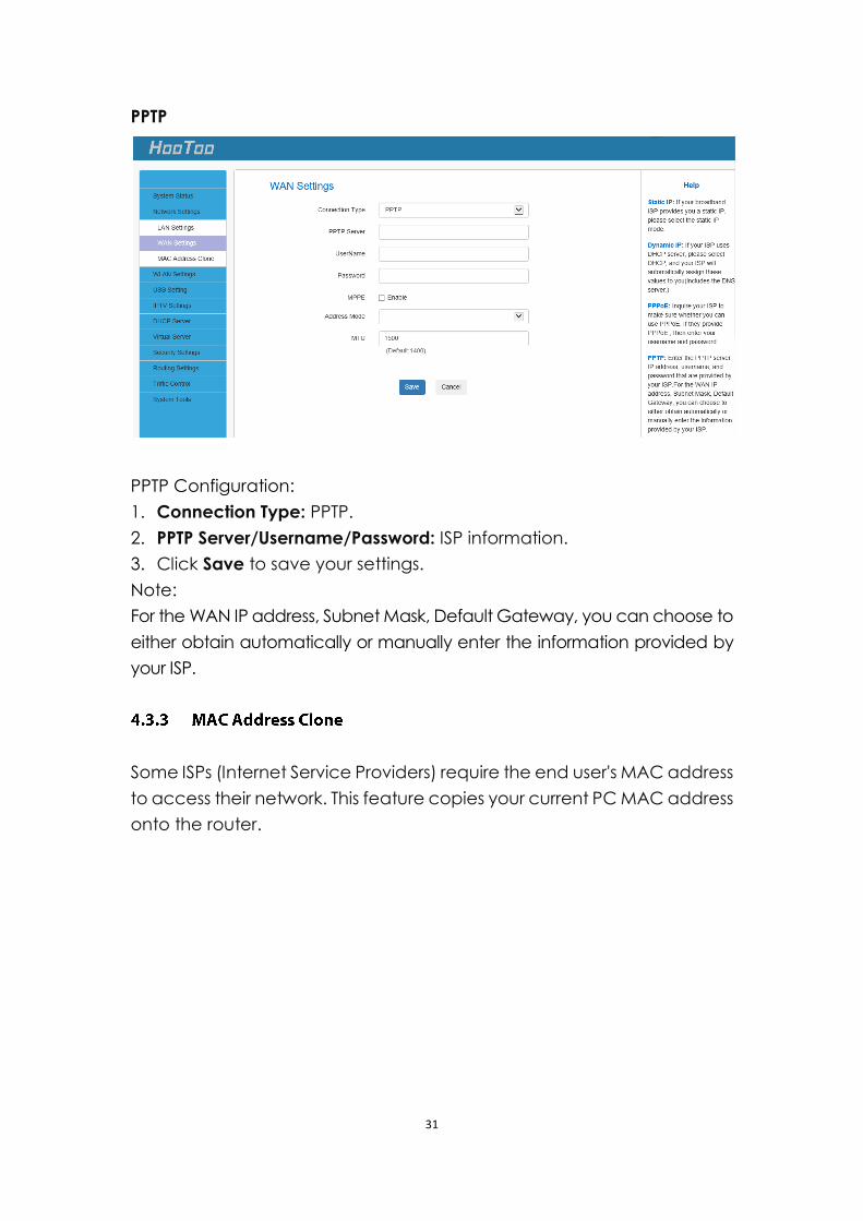
PPTP
PPTP Configuration:
1. Connection Type: PPTP.
2. PPTP Server/Username/Password: ISP information.
3. Click Save to save your settings.
Note:
For the WAN IP address, Subnet Mask, Default Gateway, you can choose to
either obtain automatically or manually enter the information provided by
your ISP.
Some ISPs (Internet Service Providers) require the end user's MAC address
to access their network. This feature copies your current PC MAC address
onto the router.
32
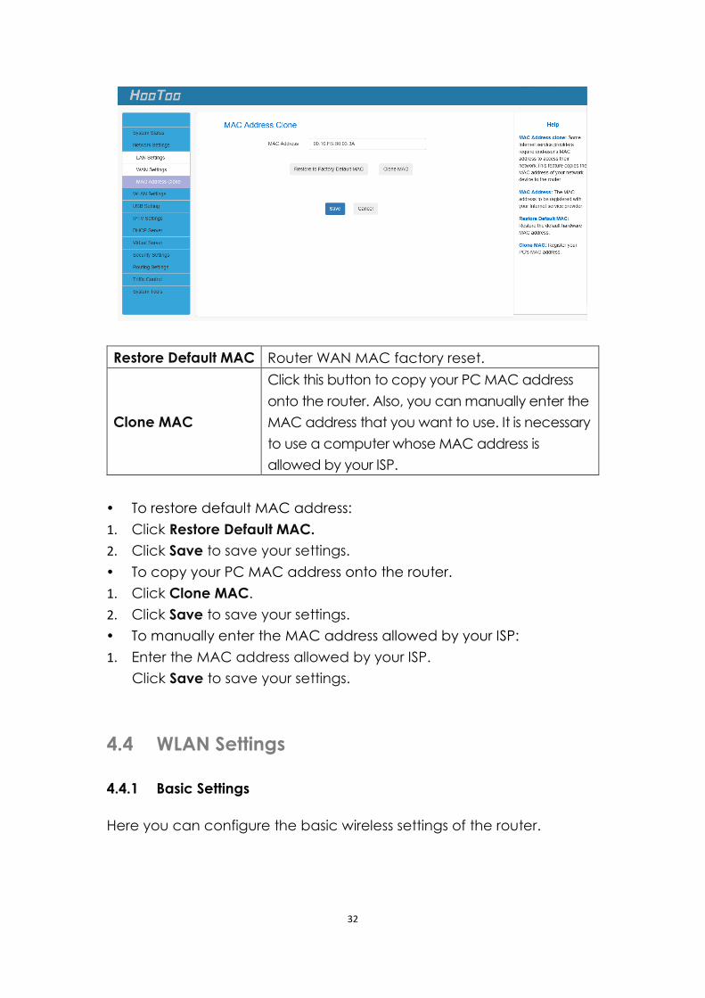
Restore Default MAC Router WAN MAC factory reset.
Clone MAC
Click this button to copy your PC MAC address
onto the router. Also, you can manually enter the
MAC address that you want to use. It is necessary
to use a computer whose MAC address is
allowed by your ISP.
To restore default MAC address:
1. Click Restore Default MAC.
2. Click Save to save your settings.
To copy your PC MAC address onto the router.
1. Click Clone MAC.
2. Click Save to save your settings.
To manually enter the MAC address allowed by your ISP:
1. Enter the MAC address allowed by your ISP.
Click Save to save your settings.
4.4 WLAN Settings
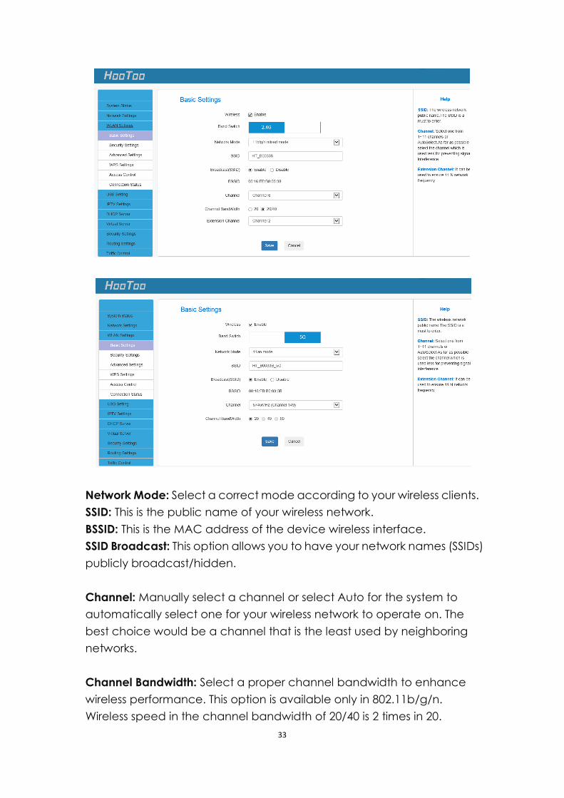
4.4.1 Basic Settings
Here you can configure the basic wireless settings of the router.
33
Network Mode: Select a correct mode according to your wireless clients.
SSID: This is the public name of your wireless network.
BSSID: This is the MAC address of the device wireless interface.
SSID Broadcast: This option allows you to have your network names (SSIDs)
publicly broadcast/hidden.
Channel: Manually select a channel or select Auto for the system to
automatically select one for your wireless network to operate on. The
best choice would be a channel that is the least used by neighboring
networks.
Channel Bandwidth: Select a proper channel bandwidth to enhance
wireless performance. This option is available only in 802.11b/g/n.
Wireless speed in the channel bandwidth of 20/40 is 2 times in 20.
34
Extension Channel: This is used to ensure N speeds for 802.11n devices
on the network. This option is available only in 11b/g/n mixed mode
with channel bandwidth of 20/40.
Note:If you are not an advanced user, it is advisable to only change
the SSID (name of the network) and channel and leave other
parameters unaltered.
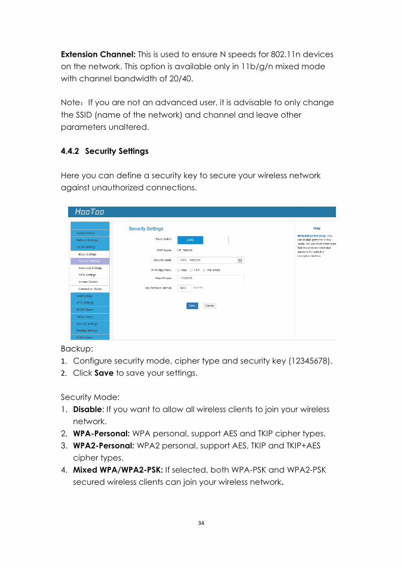
4.4.2 Security Settings
Here you can define a security key to secure your wireless network
against unauthorized connections.
Backup:
1. Configure security mode, cipher type and security key (12345678).
2. Click Save to save your settings.
Security Mode:
1. Disable: If you want to allow all wireless clients to join your wireless
network.
2. WPA-Personal: WPA personal, support AES and TKIP cipher types.
3. WPA2-Personal: WPA2 personal, support AES, TKIP and TKIP+AES
cipher types.
4. Mixed WPA/WPA2-PSK: If selected, both WPA-PSK and WPA2-PSK
secured wireless clients can join your wireless network.
35
WPA cipher type:
1. AES: If selected, wireless speed can reach up to 300Mbps.
2. TKIP: If selected, wireless speed can reach up to 54Mbps.
3. TKIP&AES: If selected, both AES and TKIP secured wireless clients can
join your wireless network.
Key Renewal Interval: Enter a valid time period for the key to be changed.
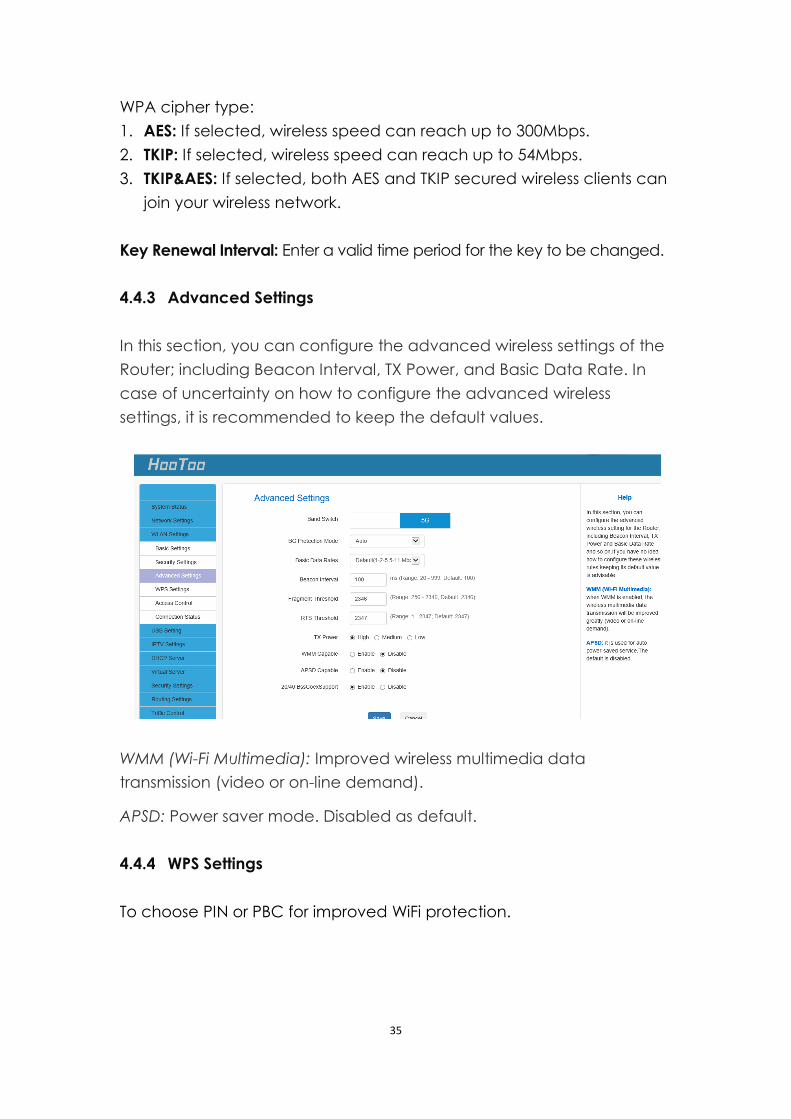
4.4.3 Advanced Settings
In this section, you can configure the advanced wireless settings of the
Router; including Beacon Interval, TX Power, and Basic Data Rate. In
case of uncertainty on how to configure the advanced wireless
settings, it is recommended to keep the default values.
WMM (Wi-Fi Multimedia): Improved wireless multimedia data
transmission (video or on-line demand).
APSD: Power saver mode. Disabled as default.
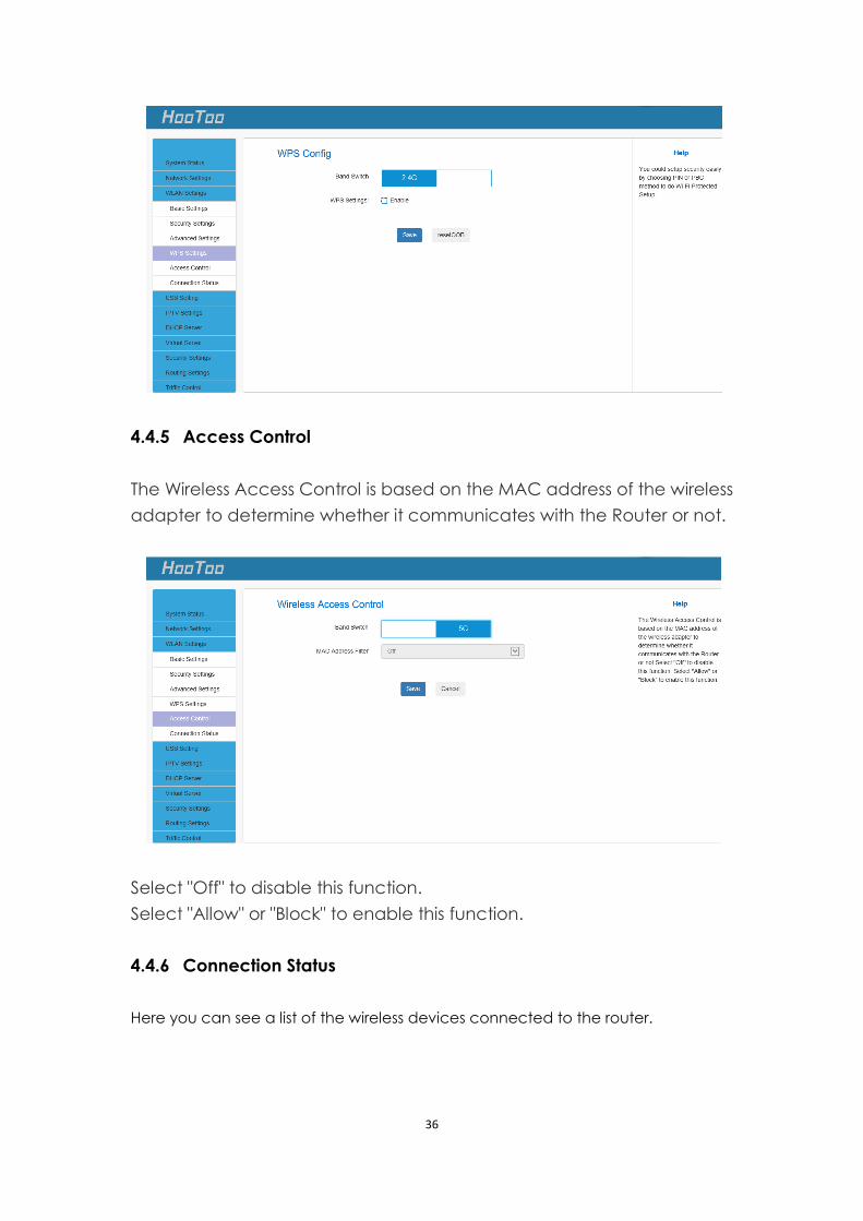
4.4.4 WPS Settings
To choose PIN or PBC for improved WiFi protection.
36
4.4.5 Access Control
The Wireless Access Control is based on the MAC address of the wireless
adapter to determine whether it communicates with the Router or not.
Select "Off" to disable this function.
Select "Allow" or "Block" to enable this function.
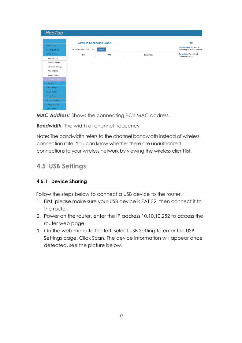
4.4.6 Connection Status
Here you can see a list of the wireless devices connected to the router.
37
MAC Address: Shows the connecting PC's MAC address.
Bandwidth: The width of channel frequency
Note: The bandwidth refers to the channel bandwidth instead of wireless
connection rate. You can know whether there are unauthorized
connections to your wireless network by viewing the wireless client list.
4.5 USB Settings
4.5.1 Device Sharing
Follow the steps below to connect a USB device to the router.
1. First, please make sure your USB device is FAT 32, then connect it to
the router.
2. Power on the router, enter the IP address 10.10.10.252 to access the
router web page.
3. On the web menu to the left, select USB Setting to enter the USB
Settings page. Click Scan. The device information will appear once
detected, see the picture below.
38
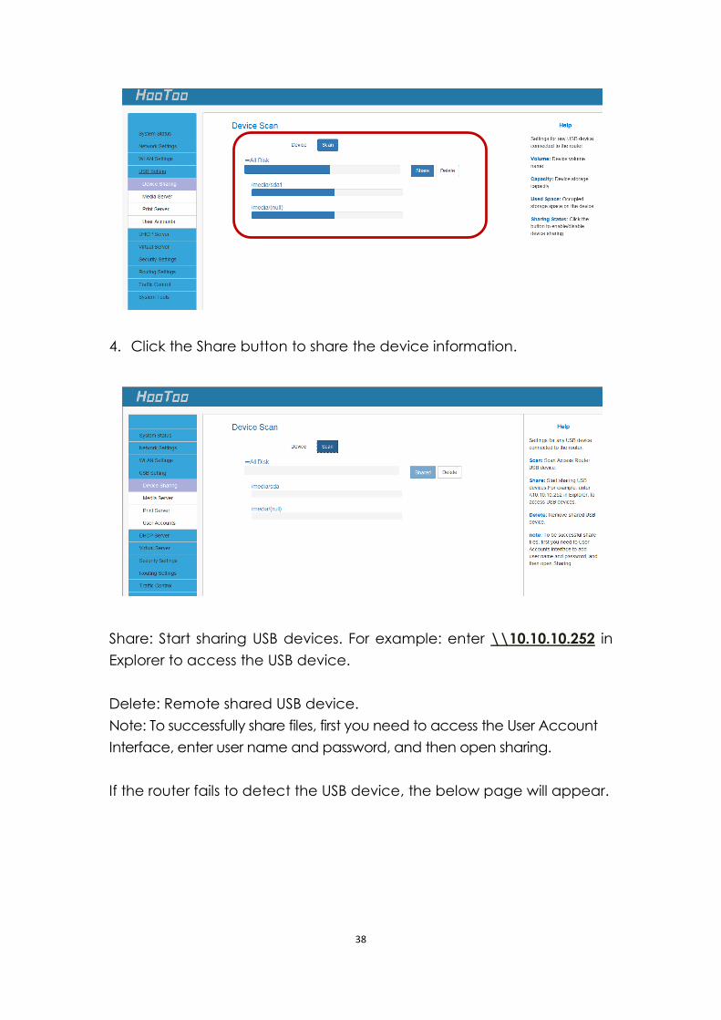
4. Click the Share button to share the device information.
Share: Start sharing USB devices. For example: enter \\10.10.10.252 in
Explorer to access the USB device.
Delete: Remote shared USB device.
Note: To successfully share files, first you need to access the User Account
Interface, enter user name and password, and then open sharing.
If the router fails to detect the USB device, the below page will appear.
39
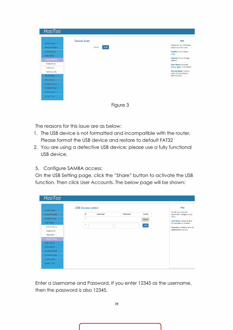
Figure 3
The reasons for this issue are as below:
1. The USB device is not formatted and incompatible with the router.
Please format the USB device and restore to default FAT32
2. You are using a defective USB device; please use a fully functional
USB device.
5. Configure SAMBA access:
On the USB Setting page, click the “Share” button to activate the USB
function. Then click User Accounts. The below page will be shown:
Enter a Username and Password. If you enter 12345 as the username,
then the password is also 12345.
40
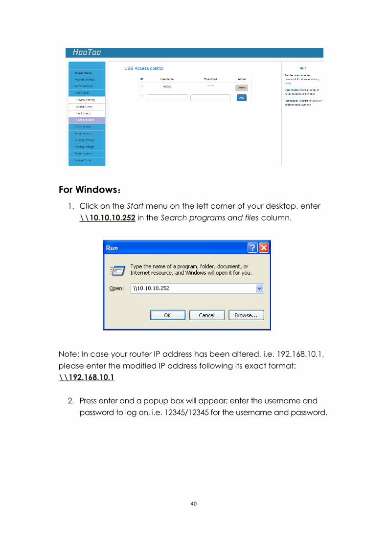
For Windows:
1. Click on the Start menu on the left corner of your desktop, enter
\\10.10.10.252 in the Search programs and files column.
Note: In case your router IP address has been altered, i.e. 192.168.10.1,
please enter the modified IP address following its exact format:
\\192.168.10.1
2. Press enter and a popup box will appear; enter the username and
password to log on, i.e. 12345/12345 for the username and password.
41
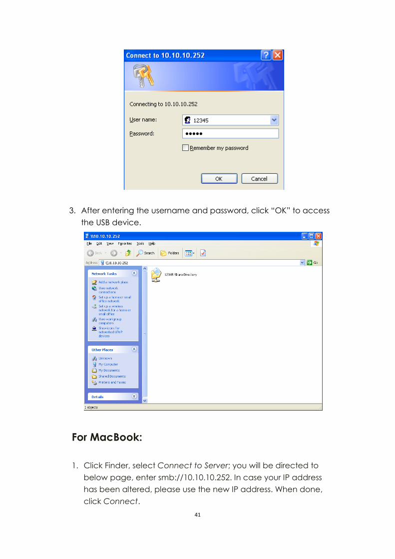
3. After entering the username and password, click “OK” to access
the USB device.
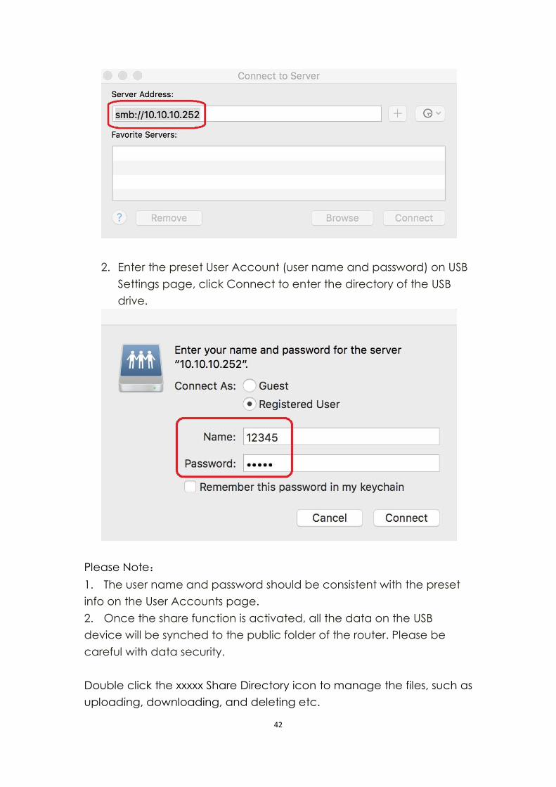
For MacBook:
1. Click Finder, select Connect to Server; you will be directed to
below page, enter smb://10.10.10.252. In case your IP address
has been altered, please use the new IP address. When done,
click Connect.
42
2. Enter the preset User Account (user name and password) on USB
Settings page, click Connect to enter the directory of the USB
drive.
Please Note:
1. The user name and password should be consistent with the preset
info on the User Accounts page.
2. Once the share function is activated, all the data on the USB
device will be synched to the public folder of the router. Please be
careful with data security.
Double click the xxxxx Share Directory icon to manage the files, such as
uploading, downloading, and deleting etc.
43
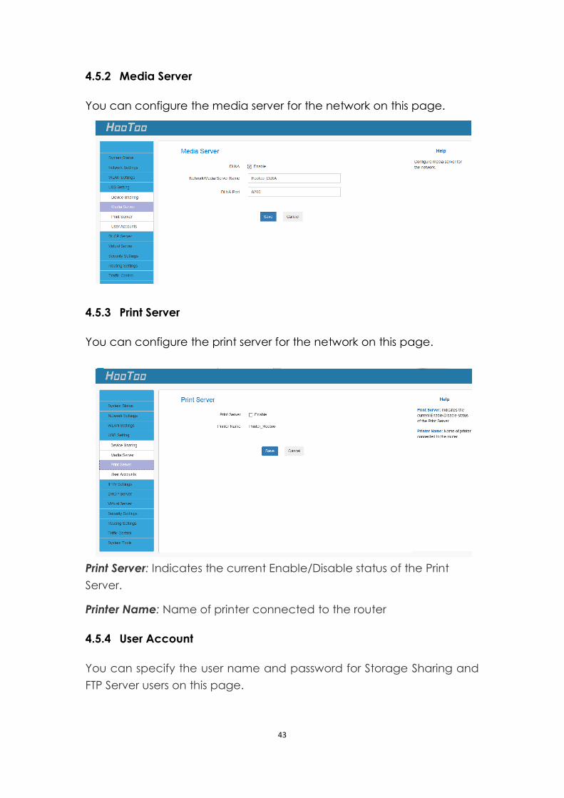
4.5.2 Media Server
You can configure the media server for the network on this page.
4.5.3 Print Server
You can configure the print server for the network on this page.
Print Server: Indicates the current Enable/Disable status of the Print
Server.
Printer Name: Name of printer connected to the router
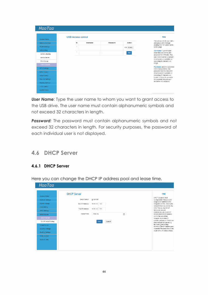
4.5.4 User Account
You can specify the user name and password for Storage Sharing and
FTP Server users on this page.
44
User Name: Type the user name to whom you want to grant access to
the USB drive. The user name must contain alphanumeric symbols and
not exceed 32 characters in length.
Password: The password must contain alphanumeric symbols and not
exceed 32 characters in length. For security purposes, the password of
each individual user is not displayed.
4.6 DHCP Server
4.6.1 DHCP Server
Here you can change the DHCP IP address pool and lease time.
45
DHCP Server Configuration:
1. DHCP Server: Enable/disable the DHCP server.
2. Start IP/End IP: Specify Start/End IP addresses of the IP address pool.
These addresses should be part of the same IP address subnet as
the router LAN IP address.
3. Lease Time: Time length for the IP address to be assigned to each
device before it is refreshed.
4. Click Save to save your settings.
Note:
1. By default, the router performs as a DHCP server. Do not disable the
DHCP server feature unless you want to manually configure TCP/IP
settings for all PCs on your LAN.
2. Lease time will be renewed automatically upon expiration. No
additional configuration is needed.
3. If you are not an advanced user, the default DHCP server settings
are recommended.
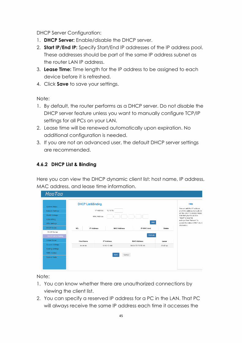
4.6.2 DHCP List & Binding
Here you can view the DHCP dynamic client list: host name, IP address,
MAC address, and lease time information.
Note:
1. You can know whether there are unauthorized connections by
viewing the client list.
2. You can specify a reserved IP address for a PC in the LAN. That PC
will always receive the same IP address each time it accesses the
46
DHCP server. Reserved IP addresses can be assigned to servers that
require permanent IP settings.
3. If the IP address you have reserved for your PC is currently used by
another client, then you will not be able to obtain a new IP address
from the device DHCP server, instead, you have to manually specify
a different IP address for your PC to access the Internet.
4. For PCs that have already obtained IP addresses, you may need to
perform the Repair action to activate the configured static IP
addresses.
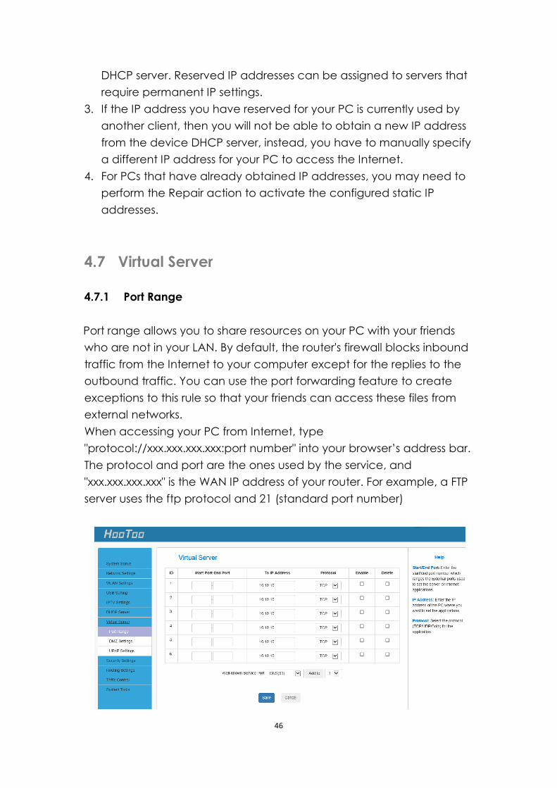
4.7 Virtual Server
4.7.1 Port Range
Port range allows you to share resources on your PC with your friends
who are not in your LAN. By default, the router's firewall blocks inbound
traffic from the Internet to your computer except for the replies to the
outbound traffic. You can use the port forwarding feature to create
exceptions to this rule so that your friends can access these files from
external networks.
When accessing your PC from Internet, type
"protocol://xxx.xxx.xxx.xxx:port number" into your browser’s address bar.
The protocol and port are the ones used by the service, and
"xxx.xxx.xxx.xxx" is the WAN IP address of your router. For example, a FTP
server uses the ftp protocol and 21 (standard port number)
47
Start/End Port: Enter the start/end port number within the ranges forwarded
from the external ports to set the server or Internet applications.
IP Address: Enter the IP address of the PC where you want to set the
applications.
Protocol: Select the protocol (TCP/UDP/Both) for the application
Enable:Activate this rule.
Note:
1. Make sure your WAN IP address (Internet IP address) is a public IP
address. Private IP addresses are not routed on the Internet.
2. Make sure you enter the correct service port numbers.
3. To ensure that your server computer always has the same IP address,
assign a static IP address to your PC.
4. Operating System built-in firewall and some anti-virus programs may
block other PCs from accessing resources on your PC. So it is advisable
to disable them before using this feature.
5. When finished, click Save to save your settings.
For example: if your WAN IP address is 202.33.56.88, when accessing your
FTP server from external network, your friends only need to enter
ftp://202.33.56.88:21 in their browsers.
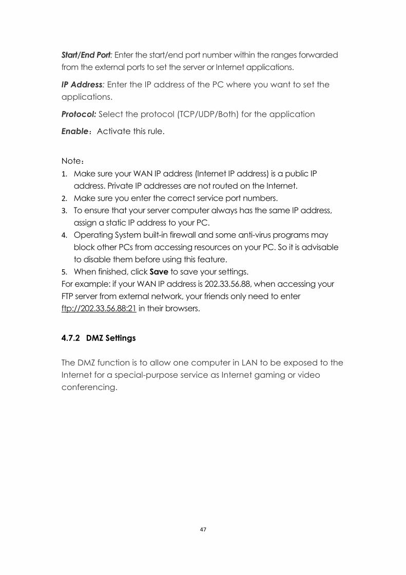
4.7.2 DMZ Settings
The DMZ function is to allow one computer in LAN to be exposed to the
Internet for a special-purpose service as Internet gaming or video
conferencing.
48
DMZ Host IP: The IP address of the computer you want to expose.
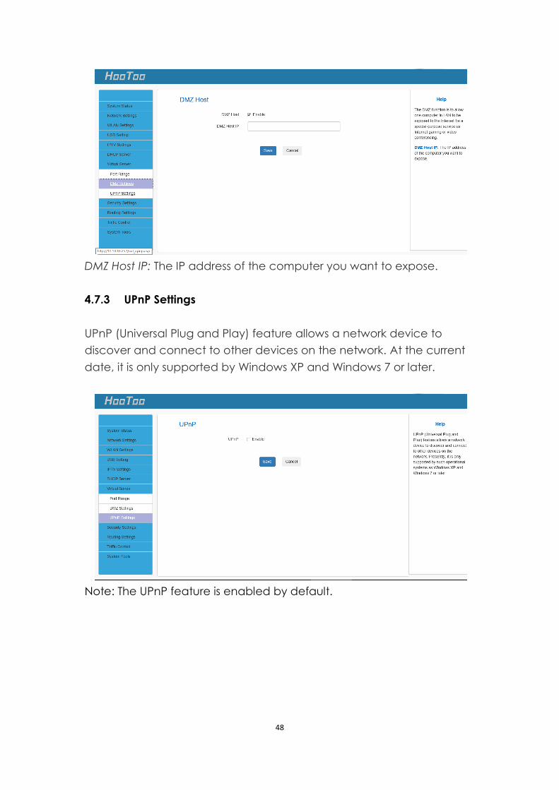
4.7.3 UPnP Settings
UPnP (Universal Plug and Play) feature allows a network device to
discover and connect to other devices on the network. At the current
date, it is only supported by Windows XP and Windows 7 or later.
Note: The UPnP feature is enabled by default.
49
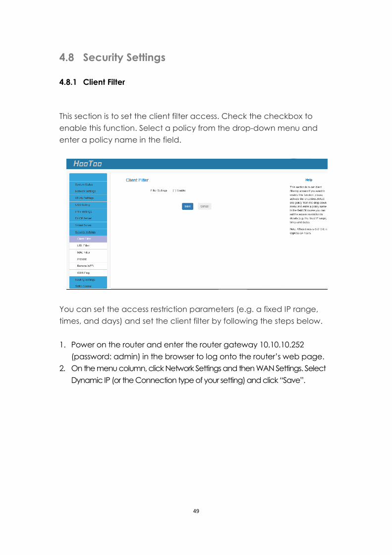
4.8 Security Settings
4.8.1 Client Filter
This section is to set the client filter access. Check the checkbox to
enable this function. Select a policy from the drop-down menu and
enter a policy name in the field.
You can set the access restriction parameters (e.g. a fixed IP range,
times, and days) and set the client filter by following the steps below.
1. Power on the router and enter the router gateway 10.10.10.252
(password: admin) in the browser to log onto the router’s web page.
2. On the menu column, click Network Settings and then WAN Settings. Select
Dynamic IP (or the Connection type of your setting) and click “Save”.
50
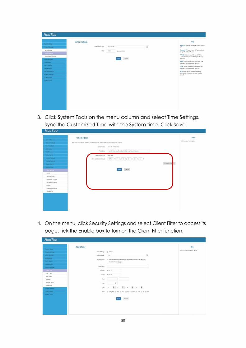
3. Click System Tools on the menu column and select Time Settings.
Sync the Customized Time with the System time. Click Save.
4. On the menu, click Security Settings and select Client Filter to access its
page. Tick the Enable box to turn on the Client Filter function.
51
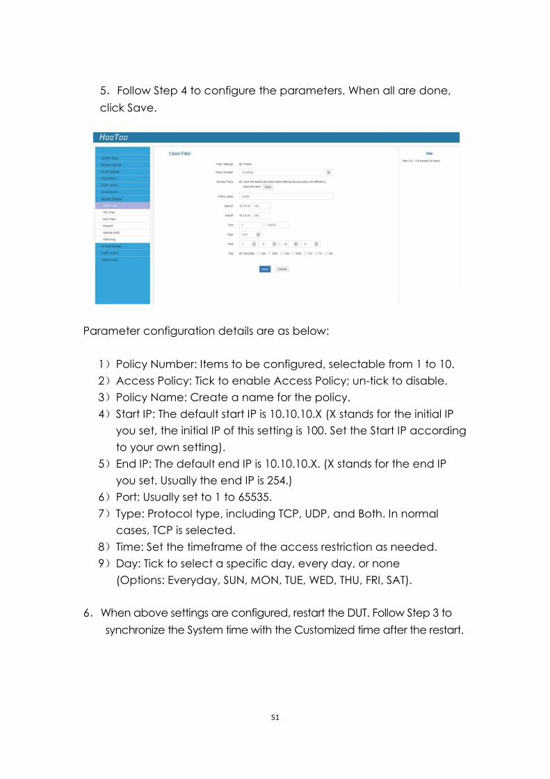
5.Follow Step 4 to configure the parameters. When all are done,
click Save.
Parameter configuration details are as below:
1) Policy Number: Items to be configured, selectable from 1 to 10.
2) Access Policy: Tick to enable Access Policy; un-tick to disable.
3) Policy Name: Create a name for the policy.
4) Start IP: The default start IP is 10.10.10.X (X stands for the initial IP
you set, the initial IP of this setting is 100. Set the Start IP according
to your own setting).
5) End IP: The default end IP is 10.10.10.X. (X stands for the end IP
you set. Usually the end IP is 254.)
6) Port: Usually set to 1 to 65535.
7) Type: Protocol type, including TCP, UDP, and Both. In normal
cases, TCP is selected.
8) Time: Set the timeframe of the access restriction as needed.
9) Day: Tick to select a specific day, every day, or none
(Options: Everyday, SUN, MON, TUE, WED, THU, FRI, SAT).
6.When above settings are configured, restart the DUT. Follow Step 3 to
synchronize the System time with the Customized time after the restart.
52
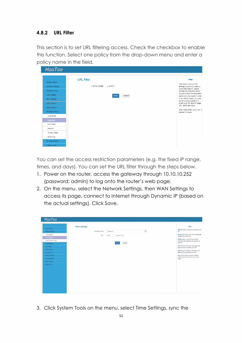
4.8.2 URL Filter
This section is to set URL filtering access. Check the checkbox to enable
this function. Select one policy from the drop-down menu and enter a
policy name in the field.
You can set the access restriction parameters (e.g. the fixed IP range,
times, and days). You can set the URL filter through the steps below.
1. Power on the router, access the gateway through 10.10.10.252
(password: admin) to log onto the router’s web page.
2. On the menu, select the Network Settings, then WAN Settings to
access its page, connect to Internet through Dynamic IP (based on
the actual settings). Click Save.
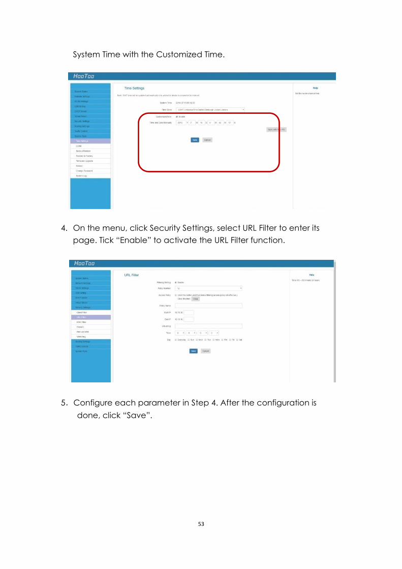
3. Click System Tools on the menu, select Time Settings, sync the
53
System Time with the Customized Time.
4. On the menu, click Security Settings, select URL Filter to enter its
page. Tick “Enable” to activate the URL Filter function.
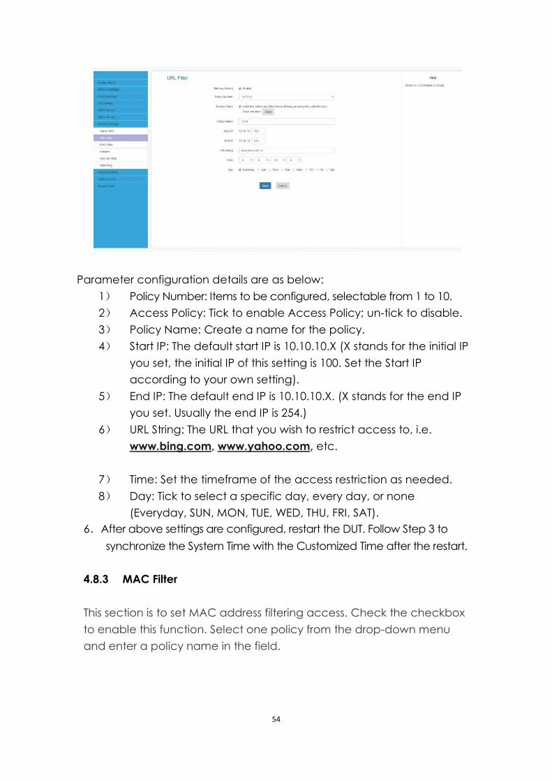
5.Configure each parameter in Step 4. After the configuration is
done, click “Save”.
54
Parameter configuration details are as below:
1) Policy Number: Items to be configured, selectable from 1 to 10.
2) Access Policy: Tick to enable Access Policy; un-tick to disable.
3) Policy Name: Create a name for the policy.
4) Start IP: The default start IP is 10.10.10.X (X stands for the initial IP
you set, the initial IP of this setting is 100. Set the Start IP
according to your own setting).
5) End IP: The default end IP is 10.10.10.X. (X stands for the end IP
you set. Usually the end IP is 254.)
6) URL String: The URL that you wish to restrict access to, i.e.
www.bing.com, www.yahoo.com, etc.
7) Time: Set the timeframe of the access restriction as needed.
8) Day: Tick to select a specific day, every day, or none
(Everyday, SUN, MON, TUE, WED, THU, FRI, SAT).
6.After above settings are configured, restart the DUT. Follow Step 3 to
synchronize the System Time with the Customized Time after the restart.
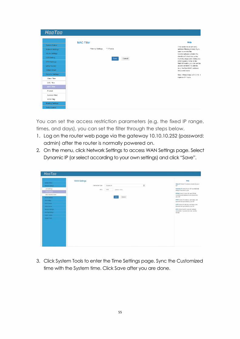
4.8.3 MAC Filter
This section is to set MAC address filtering access. Check the checkbox
to enable this function. Select one policy from the drop-down menu
and enter a policy name in the field.
55
You can set the access restriction parameters (e.g. the fixed IP range,
times, and days), you can set the filter through the steps below.
1. Log on the router web page via the gateway 10.10.10.252 (password:
admin) after the router is normally powered on.
2. On the menu, click Network Settings to access WAN Settings page. Select
Dynamic IP (or select according to your own settings) and click “Save”.
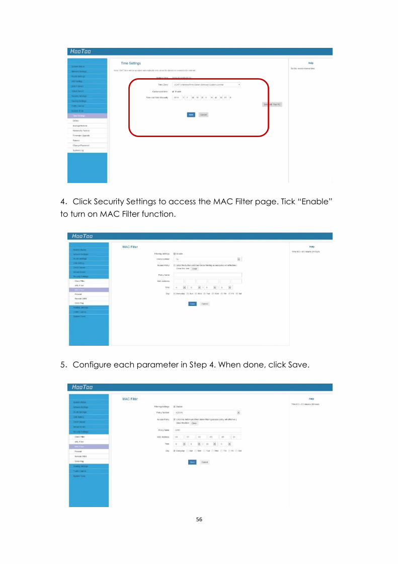
3. Click System Tools to enter the Time Settings page. Sync the Customized
time with the System time. Click Save after you are done.
56
4.Click Security Settings to access the MAC Filter page. Tick “Enable”
to turn on MAC Filter function.
5.Configure each parameter in Step 4. When done, click Save.
57
Parameter configuration details are as below:
1) Policy Number: Items to be configured, selectable from 1 to 10.
2) Access Policy: Tick to enable Access Policy; un-tick to disable.
3) Policy Name: Create a name for the policy.
4) MAC Address: The MAC address for wired and wireless
internet connection. Enter the wired and wireless MAC
address respectively for when the PC is connected to DUT
with wire and wirelessly.
5) Time: Set the timeframe of the access restriction as needed.
6) Day: Tick to select a specific day, every day, or none
(Everyday, SUN, MON, TUE, WED, THU, FRI, SAT).
6.After above settings are done, restart the DUT. Follow Step 3 to sync
the System Time with the Customized Time after the restart.
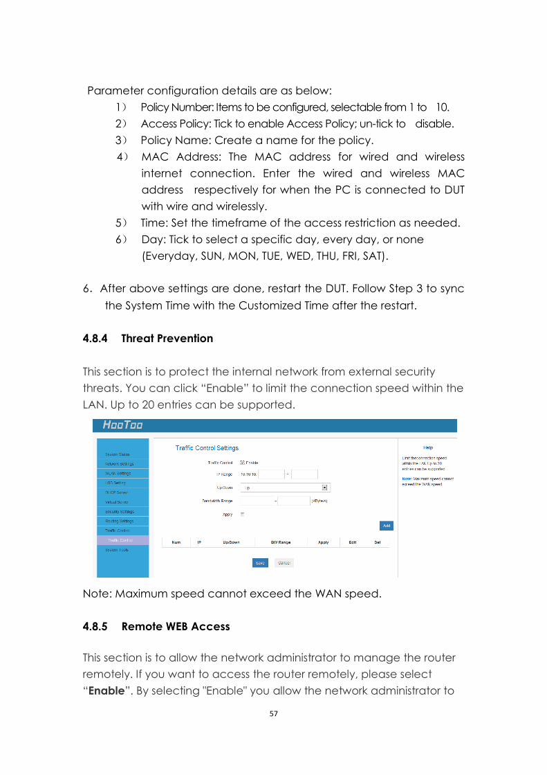
4.8.4 Threat Prevention
This section is to protect the internal network from external security
threats. You can click “Enable” to limit the connection speed within the
LAN. Up to 20 entries can be supported.
Note: Maximum speed cannot exceed the WAN speed.
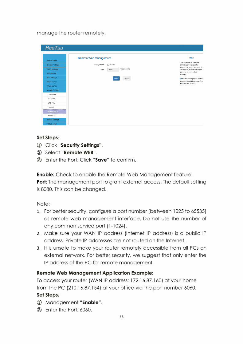
4.8.5 Remote WEB Access
This section is to allow the network administrator to manage the router
remotely. If you want to access the router remotely, please select
“Enable”. By selecting "Enable" you allow the network administrator to
58
manage the router remotely.
Set Steps:
① Click “Security Settings”.
② Select “Remote WEB”.
③ Enter the Port. Click “Save” to confirm.
Enable: Check to enable the Remote Web Management feature.
Port: The management port to grant external access. The default setting
is 8080. This can be changed.
Note:
1. For better security, configure a port number (between 1025 to 65535)
as remote web management interface. Do not use the number of
any common service port (1-1024).
2. Make sure your WAN IP address (Internet IP address) is a public IP
address. Private IP addresses are not routed on the Internet.
3. It is unsafe to make your router remotely accessible from all PCs on
external network. For better security, we suggest that only enter the
IP address of the PC for remote management.
Remote Web Management Application Example:
To access your router (WAN IP address: 172.16.87.160) at your home
from the PC (210.16.87.154) at your office via the port number 6060.
Set Steps:
① Management “Enable”.
② Enter the Port: 6060.
59
③ Click “Save” to save your settings.
In the PC 210.16.87.154 Type “http:// 172.16.87.160:6060” into your
browser’s address or location field and you can access the router
at your home remotely.
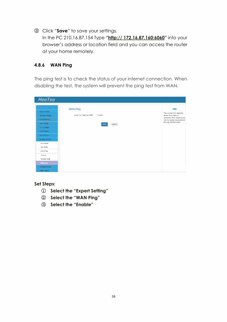
4.8.6 WAN Ping
The ping test is to check the status of your internet connection. When
disabling the test, the system will prevent the ping test from WAN.
Set Steps:
① Select the “Expert Setting”
② Select the “WAN Ping”
③ Select the “Enable”
60
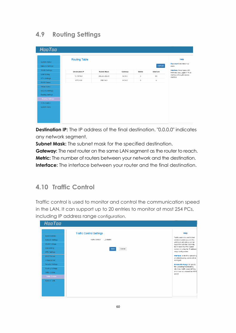
4.9 Routing Settings
Destination IP: The IP address of the final destination. "0.0.0.0" indicates
any network segment.
Subnet Mask: The subnet mask for the specified destination.
Gateway: The next router on the same LAN segment as the router to reach.
Metric: The number of routers between your network and the destination.
Interface: The interface between your router and the final destination.
4.10 Traffic Control
Traffic control is used to monitor and control the communication speed
in the LAN. It can support up to 20 entries to monitor at most 254 PCs,
including IP address range configuration.
61
Interface: To limit the uploading/downloading bandwidth in WAN port.
Bandwidth Range: To specify the uploading/downloading Min/Max
traffic speed (KB/s) - that cannot exceed WAN speed.
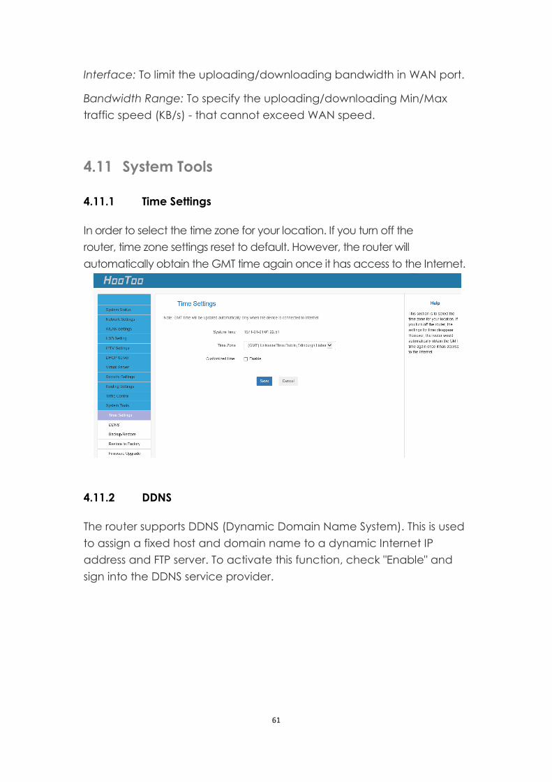
4.11 System Tools
4.11.1 Time Settings
In order to select the time zone for your location. If you turn off the
router, time zone settings reset to default. However, the router will
automatically obtain the GMT time again once it has access to the Internet.
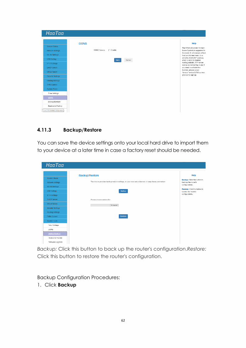
4.11.2 DDNS
The router supports DDNS (Dynamic Domain Name System). This is used
to assign a fixed host and domain name to a dynamic Internet IP
address and FTP server. To activate this function, check "Enable" and
sign into the DDNS service provider.
62
4.11.3 Backup/Restore
You can save the device settings onto your local hard drive to import them
to your device at a later time in case a factory reset should be needed.
Backup: Click this button to back up the router's configuration.Restore:
Click this button to restore the router's configuration.
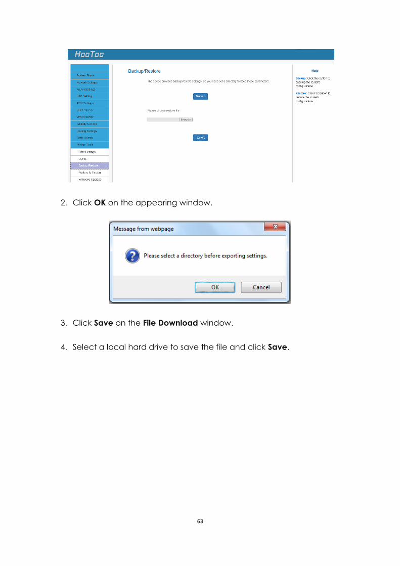
Backup Configuration Procedures:
1. Click Backup
63
2. Click OK on the appearing window.
3. Click Save on the File Download window.
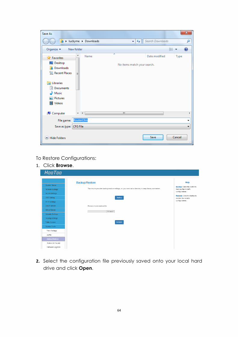
4. Select a local hard drive to save the file and click Save.
64
To Restore Configurations:
1. Click Browse.
2. Select the configuration file previously saved onto your local hard
drive and click Open.
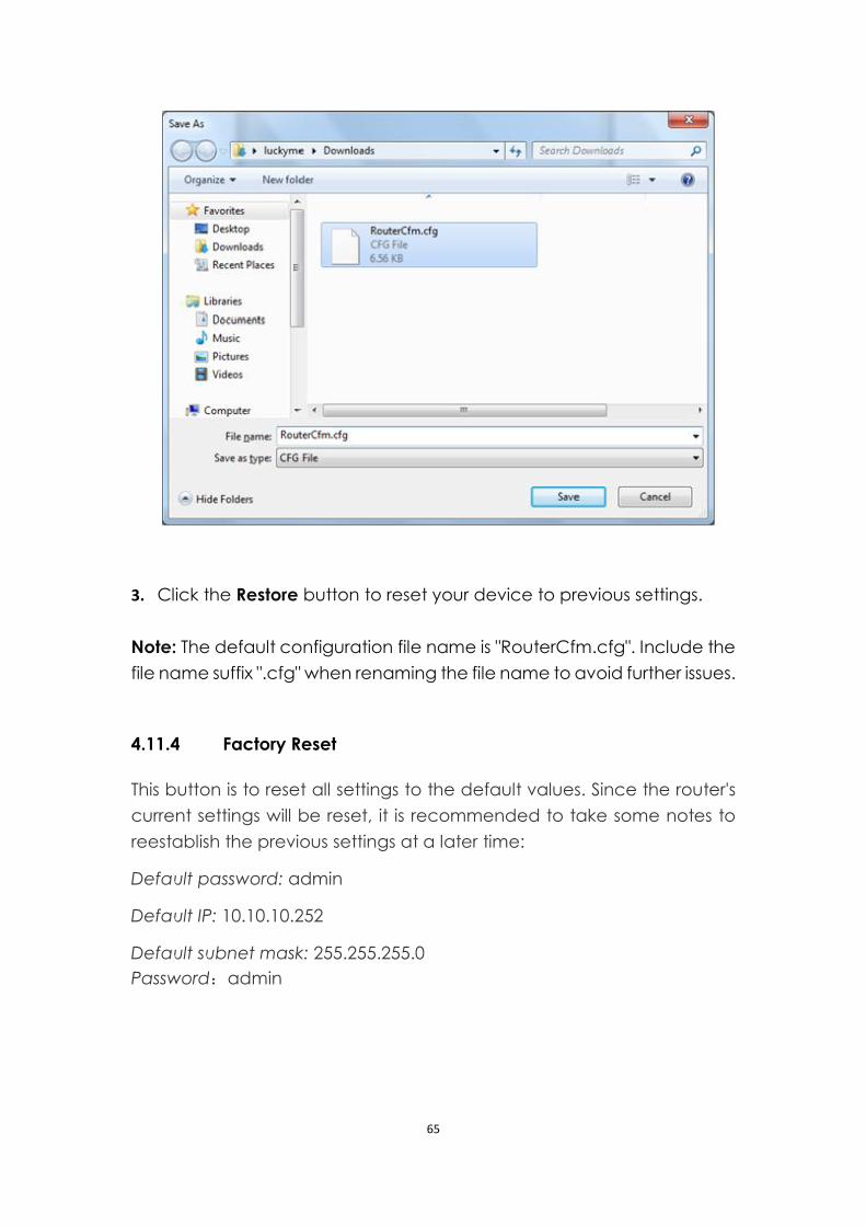
65
3. Click the Restore button to reset your device to previous settings.
Note: The default configuration file name is "RouterCfm.cfg". Include the
file name suffix ".cfg" when renaming the file name to avoid further issues.
4.11.4 Factory Reset
This button is to reset all settings to the default values. Since the router's
current settings will be reset, it is recommended to take some notes to
reestablish the previous settings at a later time:
Default password: admin
Default IP: 10.10.10.252
Default subnet mask: 255.255.255.0
Password:admin
66
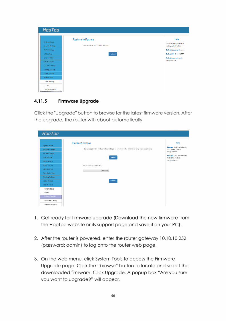
4.11.5 Firmware Upgrade
Click the "Upgrade" button to browse for the latest firmware version. After
the upgrade, the router will reboot automatically.
1. Get ready for firmware upgrade (Download the new firmware from
the HooToo website or its support page and save it on your PC).
2. After the router is powered, enter the router gateway 10.10.10.252
(password: admin) to log onto the router web page.
3. On the web menu, click System Tools to access the Firmware
Upgrade page. Click the “browse” button to locate and select the
downloaded firmware. Click Upgrade. A popup box “Are you sure
you want to upgrade?” will appear.
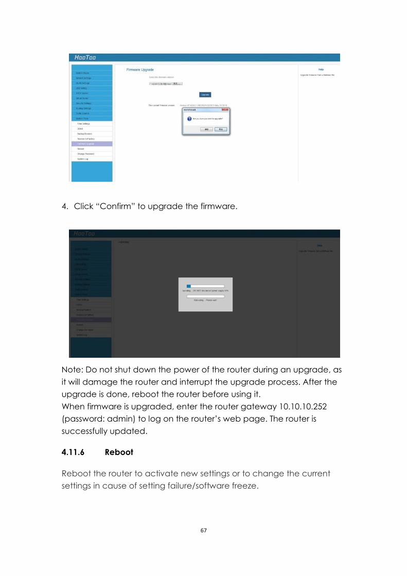
67
4. Click “Confirm” to upgrade the firmware.
Note: Do not shut down the power of the router during an upgrade, as
it will damage the router and interrupt the upgrade process. After the
upgrade is done, reboot the router before using it.
When firmware is upgraded, enter the router gateway 10.10.10.252
(password: admin) to log on the router’s web page. The router is
successfully updated.
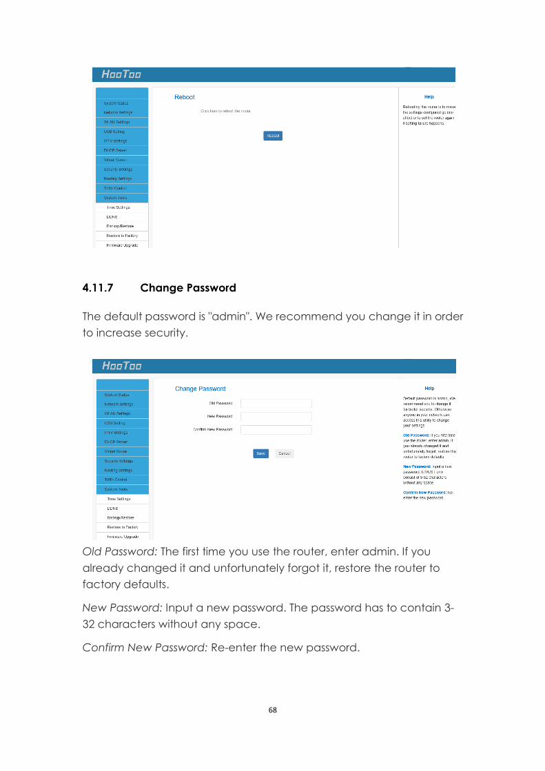
4.11.6 Reboot
Reboot the router to activate new settings or to change the current
settings in cause of setting failure/software freeze.
68
4.11.7 Change Password
The default password is "admin". We recommend you change it in order
to increase security.
Old Password: The first time you use the router, enter admin. If you
already changed it and unfortunately forgot it, restore the router to
factory defaults.
New Password: Input a new password. The password has to contain 3-
32 characters without any space.
Confirm New Password: Re-enter the new password.
69
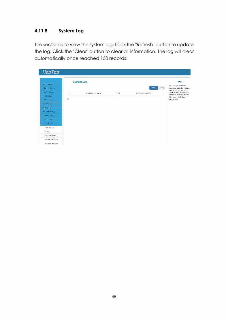
4.11.8 System Log
The section is to view the system log. Click the "Refresh" button to update
the log. Click the "Clear" button to clear all information. The log will clear
automatically once reached 150 records.
70
5 FAQs
1. Q: I cannot access the device management interface. What should I
do?
Make sure the System LED on the device front panel is on.
Make sure all cables are correctly connected and the
corresponding LAN LED on the device is on.
Verify that your PC's TCP/IP settings are configured correctly. If you
select the "Use the following IP address" option, set your PC's IP
address to any IP address between 10.10.10.2 ~ 10.10.10.254. You can
also select the "Obtain an IP address automatically" option.
Delete your browser cache and cookies or try using a different
browser. Make sure you enter 10.10.10.252 in the address bar.
Press the WPS/RST button for about 10 seconds to restore your device
to factory default settings. Then log into your device again.
2. Q: I changed the login password and unfortunately forgot it. What
should I do?
Press the WPS/RST button for over 10 seconds to restore your device to
factory default settings.
3. Q: My computer shows an IP address conflict error after connecting to
the device. What should I do?
Make sure there are no other DHCP servers on your LAN/no DHCP
servers are disabled.
Make sure the device LAN IP address is not used by other devices
on your LAN. The device default LAN IP address is 10.10.10.252.
Make sure the statically assigned IP addresses to the PCs on LAN
are not used by others PCs.
4. Q: I have problems connecting to the Internet/Secure websites do not
open or display only part of a web page. What should I do?
This problem mainly happens to users who use PPPoE or Dynamic IP
Internet connection types. You need to change the MTU size. Try
changing the MTU to 1450 or 1400. If this does not help, gradually reduce
the MTU from the maximum value until the problem disappears.
71
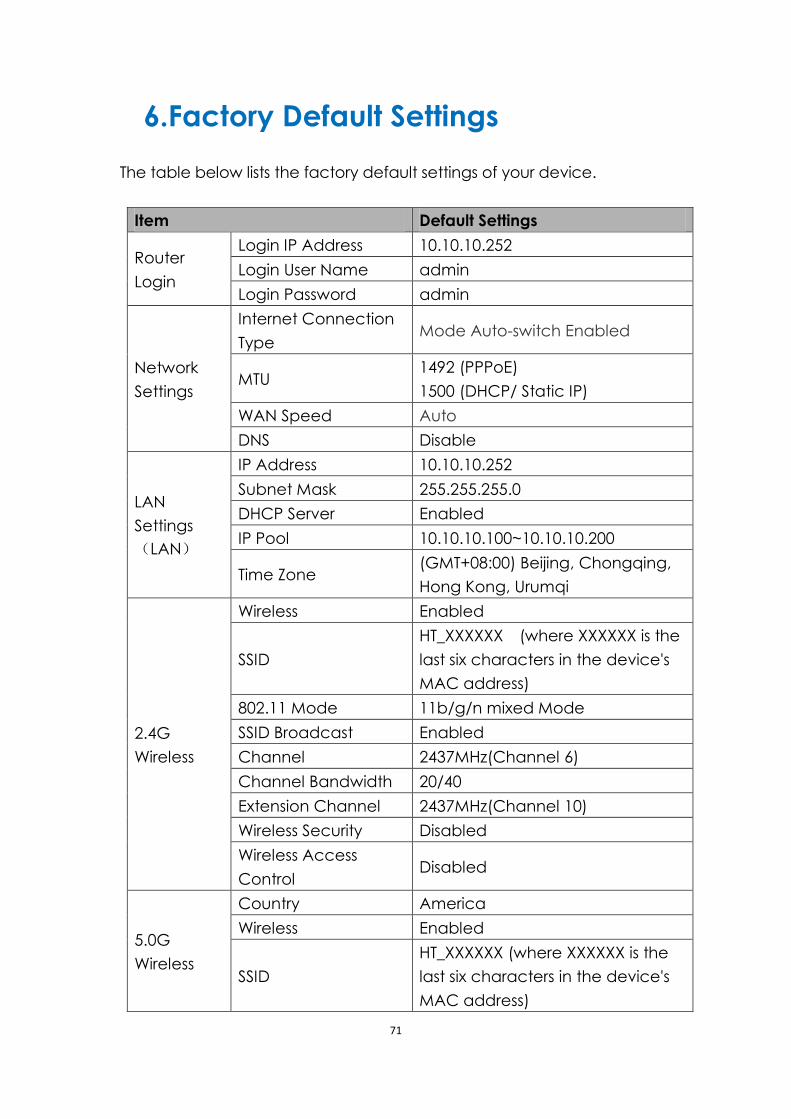
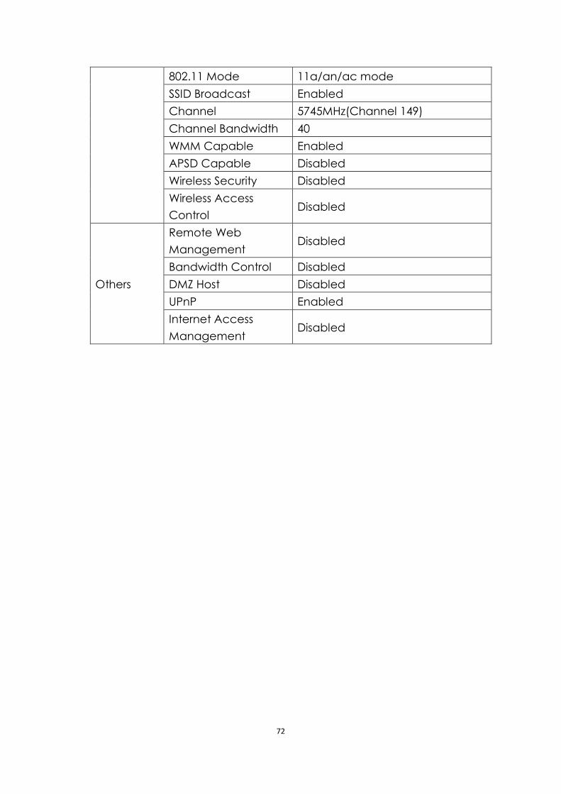
6.Factory Default Settings
The table below lists the factory default settings of your device.
Item Default Settings
Router
Login
Login IP Address 10.10.10.252
Login User Name admin
Login Password admin
Network
Settings
Internet Connection
Type Mode Auto-switch Enabled
MTU 1492 (PPPoE)
1500 (DHCP/ Static IP)
WAN Speed Auto
DNS Disable
LAN
Settings
(LAN)
IP Address 10.10.10.252
Subnet Mask 255.255.255.0
DHCP Server Enabled
IP Pool 10.10.10.100~10.10.10.200
Time Zone (GMT+08:00) Beijing, Chongqing,
Hong Kong, Urumqi
2.4G
Wireless
Wireless Enabled
SSID
HT_XXXXXX (where XXXXXX is the
last six characters in the device's
MAC address)
802.11 Mode 11b/g/n mixed Mode
SSID Broadcast Enabled
Channel 2437MHz(Channel 6)
Channel Bandwidth 20/40
Extension Channel 2437MHz(Channel 10)
Wireless Security Disabled
Wireless Access
Control Disabled
5.0G
Wireless
Country America
Wireless Enabled
SSID
HT_XXXXXX (where XXXXXX is the
last six characters in the device's
MAC address)
72
802.11 Mode 11a/an/ac mode
SSID Broadcast Enabled
Channel 5745MHz(Channel 149)
Channel Bandwidth 40
WMM Capable Enabled
APSD Capable Disabled
Wireless Security Disabled
Wireless Access
Control Disabled
Others
Remote Web
Management Disabled
Bandwidth Control Disabled
DMZ Host Disabled
UPnP Enabled
Internet Access
Management Disabled
73
Warranty
HooToo products are covered by a 12 month limited warranty from the
date of its original purchase. If any problems occur, please contact our
support team.
We can only provide after sales service for products that are sold by
HooToo or HooToo authorized retailers and distributors. If you have
purchased your unit from a different place, please contact your seller
for return and warranty issues.
74
NORTH AMERICA
E-mail :
Tel : 1-888-456-8468
Tech Support: 408-627-7503
(Monday-Friday: 9:00 – 17:00 PST)
Address: 46724 Lakeview Blvd, Fremont, CA 94538
EUROPE
E-mail:
[email protected] (UK)
support.de@ hootoo.com (DE)
support.fr@ hootoo.com (FR)
support.es@ hootoo.com (ES)
support.it@ hootoo.com (IT)
EU Importer: ZBT International Trading GmbH, Lederstr 21a,
22525 Hamburg, Deutschland
ASIA PACIFIC
E-mail: [email protected] (JP)
www.hootoo.com
FCC Compliance
This device complies with Part 15 of the FCC Rules. Operation is subject to the
following two conditions: (1) This device may not cause harmful interference, and (2)
this device must withstand any interference received, including interference that may
cause undesired operation.