Embed Size (px)
Citation preview
15Medium Access
Control Protocolsin Mobile Ad Hoc
Networks: Problemsand Solutions∗
Hongqiang Zhai and Yuguang Fang
15.1 Introduction . . . . . . . . . . . . . . . . . . . . . . . . . . . . . . . . . . . . . . . . . . 23215.2 Problems . . . . . . . . . . . . . . . . . . . . . . . . . . . . . . . . . . . . . . . . . . . . . 233
15.2.1 MAC Layer Related Problems . . . . . . . . . . . . . . . . . 233Hidden Terminal Problem • Exposed TerminalProblem • Limitation of NAV Setup Procedure• Receiver Blocking Problem • The DesiredProtocol Behaviors to Achieve Maximum SpatialReuse • Limitation of IEEE 802.11 MAC Usinga Single Channel
15.2.2 Flow Level Related Problems . . . . . . . . . . . . . . . . . . 236Intra-Flow Contention • Inter-Flow Contention
15.2.3 Physical Layer Related Issues . . . . . . . . . . . . . . . . . . 237Time-Varying Channel Condition and RateAdaptation • Link Diversity
15.3 DUCHA: A New Dual-Channel MAC Protocol . . . . . . . . . 23915.3.1 Protocol Overview . . . . . . . . . . . . . . . . . . . . . . . . . . . . 23915.3.2 Basic Message Exchange . . . . . . . . . . . . . . . . . . . . . . 239
RTS • CTS/NCTS • Data • Busy Tone • NACK
15.3.3 Solutions to the Aforementioned Problems . . . . 240Solution to the Hidden Terminal Problem • Solutionto the Exposed Terminal Problem • Solution to theReceiver Blocking Problem • Maximum SpatialReuse • Inherent Mechanisms to Solve theIntra-flow Contention Problem
15.3.4 Bandwidth Allocation . . . . . . . . . . . . . . . . . . . . . . . . 241
∗This work was supported in part by the Office of Naval Research under Young Investigator Award N000140210464and the National Science Foundation under Faculty Early Career Development Award ANI-0093241.
231
232 Handbook on Theoretical and Algorithmic Aspects of Sensor
15.4 Distributed Flow Control and Medium Access Control . 24215.4.1 Motivation . . . . . . . . . . . . . . . . . . . . . . . . . . . . . . . . . . . 24215.4.2 Solution . . . . . . . . . . . . . . . . . . . . . . . . . . . . . . . . . . . . . 242
Rule 1: Assigning High Priority of the Channel Accessto the Receiver • Rule 2: Backward-Pressure Scheduling
15.5 Rate Adaptation with Dynamic Fragmentation . . . . . . . . . 24515.5.1 Fragmentation Scheme . . . . . . . . . . . . . . . . . . . . . . . 24515.5.2 Rate-Adaptive MAC Protocol
for Fragment Bursts . . . . . . . . . . . . . . . . . . . . . . . . . . 24615.6 Opportunistic Media Access Control and Auto
Rate Protocol (OMAR) . . . . . . . . . . . . . . . . . . . . . . . . . . . . . . . . 24715.6.1 Hybrid Opportunistic Media Access . . . . . . . . . . . 247
Sender-Initiated Opportunistic Media Access• Receiver-Initiated Opportunistic Media Access
15.6.2 Rate Adaptation . . . . . . . . . . . . . . . . . . . . . . . . . . . . . . 24815.6.3 Scheduling . . . . . . . . . . . . . . . . . . . . . . . . . . . . . . . . . . 249
15.7 Conclusion . . . . . . . . . . . . . . . . . . . . . . . . . . . . . . . . . . . . . . . . . . . 249References . . . . . . . . . . . . . . . . . . . . . . . . . . . . . . . . . . . . . . . . . . . . . . . . . . . 249
15.1 Introduction
Recent advancements in wireless technologies and mankind’s long-time dream of free communicationare the driving forces behind the proliferation of wireless local area networks (WLANs) and the “hot”research activities in mobile ad hoc networks (MANETs). One of the most active topics is medium accesscontrol (MAC) protocols, which coordinate the efficient use of the limited shared wireless resource. How-ever, in these wireless networks, the limited wireless spectrum, time-varying propagation characteristics,distributed multiple access control, low complexity, and energy constraints together impose significantchallenges for MAC protocol design to provide reliable wireless communications with high data rates.
Among all MAC protocols, random medium access control (MAC) protocols have been widely studiedfor wireless networks due to their low cost and easy implementation. IEEE 802.11 MAC10 is such aprotocol that has been successfully deployed in wireless LANs and has also been incorporated in manywireless testbeds and simulation packages for wireless multihop mobile ad hoc networks. It uses four-way handshake procedures (i.e., RTS/CTS/DATA/ACK). The RTS and CTS procedures are used to avoidcollisions with long data packets. The value of the NAV (network allocation vector) carried by RTS or CTSis used to reserve the medium to avoid potential collisions (i.e., virtual carrier sensing) and thus mitigatethe hidden terminal problem. The ACK is used to confirm successful transmission without errors.
However, there are still many problems that IEEE 802.11 MAC has not adequately addressed. How todesign a more effective transmission scheme based on the channel condition is still open and challenging.How to make full use of multiuser diversity in terms of multiple transmitters with the same receiver orthe same transmitter with multiple receivers to maximize the throughput is also an interesting issue. Inaddition, in multihop ad hoc networks, the MAC layer contention or collision becomes much more severethan in the wireless LANs. Due to the MAC layer contention, the interaction or coupling among differenttraffic flows also deserves serious attention, which may limit the stability and scalability of multihop adhoc networks.
At the MAC layer, the open shared channel imposes a lot of challenges for medium access control design.The hidden terminals may introduce collisions and the exposed terminals may lead to low throughputefficiency. In addition to these two notorious problems, the receiver blocking problem (i.e., the intendedreceiver does not respond to the sender with CTS or ACK due to the interference or virtual carrier sensingoperational requirements due to the other ongoing transmissions) hence deserves serious consideration.In fact, this problem becomes more severe in multihop ad hoc networking environments and may result inthroughput inefficiency, starvation of some traffic flows or nodes or re-routing. Many proposed solutions
Medium Access Control Protocols in Mobile Ad Hoc Networks 233
actually aggravate this problem by not allowing the hidden terminal to transmit. Furthermore, how tomaximize spatial reuse by allowing the hidden terminals to receive and the exposed terminals to transmitis a very interesting issue.
Higher layer network protocols may be affected by wireless MAC protocols. It has been shown in manyarticles that multihop ad hoc networks perform poorly with TCP traffic and heavy UDP traffic.3,7,15,16,25
This is because all wireless links in the neighborhood share the same wireless resource. All traffic flowspassing through these links need to contend for the channel before transmission. Hence, severe MAClayer contention and collision can result in the contention among traffic flows. On the other hand,MAC contention can introduce network congestion with backlogged packets, which implies that networkcongestion is closely coupled with MAC contention. Some researchers have already noticed this kind ofcoupling. Fang and McDonald6 demonstrated that the throughput and delay can be affected by the pathcoupling, that is, the MAC layer contention among the nodes distributed along the node-disjoint paths.Thus, cross-layer design and optimization is necessary for MANETs.
Moreover, at the physical layer, the time-varying channel condition makes rate adaptation necessaryto improve network throughput. The diversity in the link quality due to the various channel conditionscould be exploited to design opportunistic packet scheduling. The MAC protocol should be designedaccordingly to adapt to the varying channel conditions.
In this chapter we first discuss the identified problems and challenges at different protocol layers to thedesign of MAC protocol. Then, we present several recently proposed novel schemes to address MAC layerproblems, traffic flow-related issues, rate adaptation, and link quality diversity, respectively, in Sections 15.3through 15.6. Finally, Section 15.7 concludes this chapter.
15.2 Problems
This section first discusses the inherent problems of the IEEE 802.11 MAC protocol in shared wirelesschannel environments in MANETs, and then illustrates the impact of traffic flows and physical layerchannel conditions on the performance of this MAC protocol.
15.2.1 MAC Layer Related Problems
A packet collision over the air is much more severe in multihop environments than that in wirelessLANs. Packet losses due to MAC layer contention will definitely affect the performance of the high layernetworking schemes such as the TCP congestion control and routing maintenance because a node doesnot know whether an error is due to the collision or the unreachable address. It has been shown in manyarticles that multihop ad hoc networks performs poorly with TCP traffic as well as heavy UDP traffic.3,16,25
The source of the above problems comes mainly from the MAC layer. The hidden terminals may in-troduce collisions and the exposed terminals may lead to low throughput efficiency. In addition to thesetwo notorious problems, the receiver blocking problem (i.e., the intended receiver does not respond to thesender with CTS or ACK due to the interference or virtual carrier sensing operational requirements forthe other ongoing transmissions) also deserves serious consideration. In fact, this problem becomes moresevere in multihop environments and results in throughput inefficiency and starvation of some trafficflows or nodes. The next few subsections describe a few problems in multihop mobile ad hoc networkswhen the IEEE 802.11 MAC protocol is deployed.
15.2.1.1 Hidden Terminal Problem
A hidden terminal is the one within the sensing range of the receiver, but not in the sensing range ofthe transmitter. The hidden terminal does not know that the transmitter is transmitting, and hence caninitiate a transmission, resulting in a collision at the receiving node of the ongoing transmission.
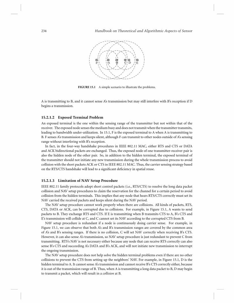
One simple example is shown in Figure 15.1, where the small circles indicate the edges of the transmissionrange and the large circles represent the edges of the sensing range. D is the hidden terminal to A when
234 Handbook on Theoretical and Algorithmic Aspects of Sensor
A B C D EF
FIGURE 15.1 A simple scenario to illustrate the problems.
A is transmitting to B, and it cannot sense A’s transmission but may still interfere with B’s reception if Dbegins a transmission.
15.2.1.2 Exposed Terminal Problem
An exposed terminal is the one within the sensing range of the transmitter but not within that of thereceiver. The exposed node senses the medium busy and does not transmit when the transmitter transmits,leading to bandwidth under-utilization. In 15.1, F is the exposed terminal to A when A is transmitting toB. F senses A’s transmission and keeps silent, although F can transmit to other nodes outside of A’s sensingrange without interfering with B’s reception.
In fact, in the four-way handshake procedures in IEEE 802.11 MAC, either RTS and CTS or DATAand ACK bidirectional packets are exchanged. Thus, the exposed node of one transmitter-receiver pair isalso the hidden node of the other pair. So, in addition to the hidden terminal, the exposed terminal ofthe transmitter should not initiate any new transmission during the whole transmission process to avoidcollision with the short packets ACK or CTS in IEEE 802.11 MAC. Thus, the carrier sensing strategy basedon the RTS/CTS handshake will lead to a significant deficiency in spatial reuse.
15.2.1.3 Limitation of NAV Setup Procedure
IEEE 802.11 family protocols adopt short control packets (i.e., RTS/CTS) to resolve the long data packetcollision and NAV setup procedures to claim the reservation for the channel for a certain period to avoidcollision from the hidden terminals. This implies that any node that hears RTS/CTS correctly must set itsNAV carried the received packets and keeps silent during the NAV period.
The NAV setup procedure cannot work properly when there are collisions. All kinds of packets, RTS,CTS, DATA or ACK, can be corrupted due to collisions. For example, in Figure 15.1, A wants to sendpackets to B. They exchange RTS and CTS. If E is transmitting when B transmits CTS to A, B’s CTS andE’s transmission will collide at C, and C cannot set its NAV according to the corrupted CTS from B.
NAV setup procedure is redundant if a node is continuously doing carrier sense. For example, inFigure 15.1, we can observe that both A’s and B’s transmission ranges are covered by the common areaof A’s and B’s sensing ranges. If there is no collision, C will set NAV correctly when receiving B’s CTS.However, it can also sense A’s transmission, so NAV setup procedure is just redundant to prevent C fromtransmitting. RTS’s NAV is not necessary either because any node that can receive RTS correctly can alsosense B’s CTS and succeeding A’s DATA and B’s ACK, and will not initiate new transmission to interruptthe ongoing transmission.
The NAV setup procedure does not help solve the hidden terminal problems even if there are no othercollisions to prevent the CTS from setting up the neighbors’ NAV. For example, in Figure 15.1, D is thehidden terminal to A. It cannot sense A’s transmission and cannot receive B’s CTS correctly either, becauseit is out of the transmission range of B. Thus, when A is transmitting a long data packet to B, D may beginto transmit a packet, which will result in a collision at B.
Medium Access Control Protocols in Mobile Ad Hoc Networks 235
15.2.1.4 Receiver Blocking Problem
The blocked receiver is the one that cannot respond to the RTS intended for this receiver due to theother ongoing transmission in its sensing range. This may result in unnecessary retransmissions of RTSrequests and subsequent DATA packet discarding. When the intended receiver is in the range of someongoing transmission, it cannot respond to the sender’s RTS according to the carrier sensing strategy inthe IEEE 802.11 standard. The sender may attempt to retransmit several times if the backoff window isshorter than the long data packet. Then, the backoff window size becomes larger and larger when theRTS transmission fails and the window size is doubled, until the sender finally discards the packet. If theongoing transmission finishes before the new sender reaches its maximum number of retransmissionsallowed, the packet in the queue of an old sender will have higher priority than a new one because theold sender resets its backoff window size and is much shorter in size than that of a new one. So the oldsender has a high probability of continuing to transmit and the new one continues doubling the backoffwindow size and discards packets when the maximum number of transmission attempts is reached. Thiswill therefore result in serious unfairness among flows and severe packet discarding.
For example, as shown in Figure 15.1, when D is transmitting to E, A will not receive the intended CTSfrom B if it sends RTS to B. This is because B cannot correctly receive A’s RTS due to collision from D’stransmission. Thus, A keeps retransmitting and doubling the contention window until it discards thepacket. If D has a burst of traffic, it will continuously occupy the channel, which will starve the flow fromA to B.
The hidden terminal problem could make the receiver blocking problem worse. In the above example,even if A has a chance to transmit a packet to B, its hidden terminal D could start transmission and collidewith A’s transmission at B because D cannot sense A’s transmission. Therefore, A almost has no chance tosuccessfully transmit a packet to B when D has packets destined to E.
15.2.1.5 The Desired Protocol Behaviors to Achieve Maximum Spatial Reuse
The desired MAC protocol for multihop and wireless mobile ad hoc networks should at least resolve thehidden terminal problem, the exposed terminal problem, and the receiver blocking problem. Therefore,the ideal protocol should guarantee that there is only one receiver in the range of the transmitter and thereis also only one transmitter in the range of the receiver. The exposed nodes may start to transmit despitethe ongoing transmission. The hidden nodes cannot initiate any transmissions but may receive packets.Thus, to maximize the spatial reuse or network capacity, it should allow multiple transmitters to transmitin the range of any transmitter and multiple receivers in the range of any receiver to receive. In addition,the transmitter should know whether its intended receiver is blocked or is just outside its transmissionrange in case it does not receive the returned CTS to avoid packet discarding and the undesirable protocolbehaviors at the higher layer, such as unnecessary rerouting requests.
15.2.1.6 Limitation of IEEE 802.11 MAC Using a Single Channel
The collisions between RTS/CTS and DATA/ACK, and that between DATA and ACK, are the culpritspreventing us from achieving the aforementioned desired protocol behaviors.
The exposed terminal cannot initiate new transmission because its transmission would have preventedthe current transmitter from correctly receiving the CTS or the ACK due to a possible collision.
The hidden terminal, which cannot sense the transmission or correctly receive the CTS, may initiate anew transmission, which will cause collision to the current ongoing transmission. In addition, it shouldnot become a receiver because its CTS/ACK may collide with the current transmission. Moreover, itsDATA packet reception can be corrupted by the ACK packet from the current receiver.
If the intended receiver for a new transmission is in the range of the ongoing transmission, it maynot be able to correctly receive RTS and/or sense the busy medium, which prevents it from returningthe CTS. Thus, the new sender cannot distinguish whether the intended receiver is blocked or out of itstransmission range.
To summarize, many aforementioned problems cannot be solved if a single channel is used in the IEEE802.11 MAC protocol.
236 Handbook on Theoretical and Algorithmic Aspects of Sensor
15.2.2 Flow Level Related Problems
In wireless multihop ad hoc networks, nodes must cooperate to forward each other’s packets through thenetworks. Due to contention for the shared channel, the throughput of each single node is limited notonly by the raw channel capacity, but also by the transmissions in its neighborhood. Thus, each multihopflow encounters contentions not only from other flows that pass by the neighborhood (i.e., the inter-flowcontention), but also from the transmissions of itself because the transmission at each hop must contend thechannel with the upstream and downstream nodes (i.e., the intra-flow contention). These two kinds of flowcontentions could result in severe collisions and congestion, and seriously limit the performance of ad hocnetworks. In the following paragraphs, we discuss in detail their impacts on the performance of MANETs.
15.2.2.1 Intra-Flow Contention
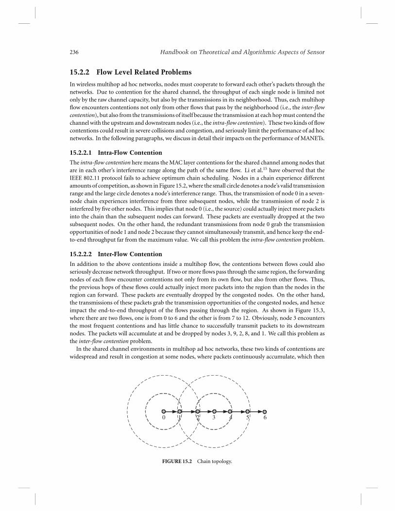
The intra-flow contention here means the MAC layer contentions for the shared channel among nodes thatare in each other’s interference range along the path of the same flow. Li et al.15 have observed that theIEEE 802.11 protocol fails to achieve optimum chain scheduling. Nodes in a chain experience differentamounts of competition, as shown in Figure 15.2, where the small circle denotes a node’s valid transmissionrange and the large circle denotes a node’s interference range. Thus, the transmission of node 0 in a seven-node chain experiences interference from three subsequent nodes, while the transmission of node 2 isinterfered by five other nodes. This implies that node 0 (i.e., the source) could actually inject more packetsinto the chain than the subsequent nodes can forward. These packets are eventually dropped at the twosubsequent nodes. On the other hand, the redundant transmissions from node 0 grab the transmissionopportunities of node 1 and node 2 because they cannot simultaneously transmit, and hence keep the end-to-end throughput far from the maximum value. We call this problem the intra-flow contention problem.
15.2.2.2 Inter-Flow Contention
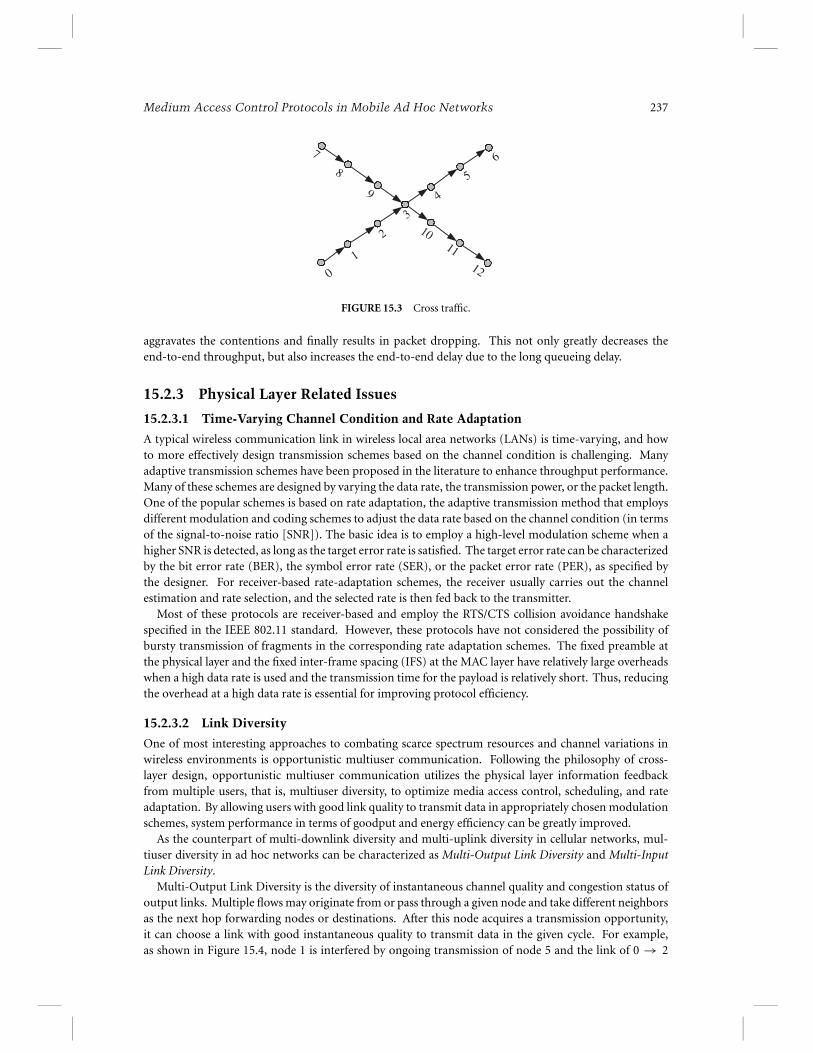
In addition to the above contentions inside a multihop flow, the contentions between flows could alsoseriously decrease network throughput. If two or more flows pass through the same region, the forwardingnodes of each flow encounter contentions not only from its own flow, but also from other flows. Thus,the previous hops of these flows could actually inject more packets into the region than the nodes in theregion can forward. These packets are eventually dropped by the congested nodes. On the other hand,the transmissions of these packets grab the transmission opportunities of the congested nodes, and henceimpact the end-to-end throughput of the flows passing through the region. As shown in Figure 15.3,where there are two flows, one is from 0 to 6 and the other is from 7 to 12. Obviously, node 3 encountersthe most frequent contentions and has little chance to successfully transmit packets to its downstreamnodes. The packets will accumulate at and be dropped by nodes 3, 9, 2, 8, and 1. We call this problem asthe inter-flow contention problem.
In the shared channel environments in multihop ad hoc networks, these two kinds of contentions arewidespread and result in congestion at some nodes, where packets continuously accumulate, which then
0 1 2 3 4 5 6
FIGURE 15.2 Chain topology.
Medium Access Control Protocols in Mobile Ad Hoc Networks 237
0
1
2
3
4
5
67
8
9
1011
12
FIGURE 15.3 Cross traffic.
aggravates the contentions and finally results in packet dropping. This not only greatly decreases theend-to-end throughput, but also increases the end-to-end delay due to the long queueing delay.
15.2.3 Physical Layer Related Issues
15.2.3.1 Time-Varying Channel Condition and Rate Adaptation
A typical wireless communication link in wireless local area networks (LANs) is time-varying, and howto more effectively design transmission schemes based on the channel condition is challenging. Manyadaptive transmission schemes have been proposed in the literature to enhance throughput performance.Many of these schemes are designed by varying the data rate, the transmission power, or the packet length.One of the popular schemes is based on rate adaptation, the adaptive transmission method that employsdifferent modulation and coding schemes to adjust the data rate based on the channel condition (in termsof the signal-to-noise ratio [SNR]). The basic idea is to employ a high-level modulation scheme when ahigher SNR is detected, as long as the target error rate is satisfied. The target error rate can be characterizedby the bit error rate (BER), the symbol error rate (SER), or the packet error rate (PER), as specified bythe designer. For receiver-based rate-adaptation schemes, the receiver usually carries out the channelestimation and rate selection, and the selected rate is then fed back to the transmitter.
Most of these protocols are receiver-based and employ the RTS/CTS collision avoidance handshakespecified in the IEEE 802.11 standard. However, these protocols have not considered the possibility ofbursty transmission of fragments in the corresponding rate adaptation schemes. The fixed preamble atthe physical layer and the fixed inter-frame spacing (IFS) at the MAC layer have relatively large overheadswhen a high data rate is used and the transmission time for the payload is relatively short. Thus, reducingthe overhead at a high data rate is essential for improving protocol efficiency.
15.2.3.2 Link Diversity
One of most interesting approaches to combating scarce spectrum resources and channel variations inwireless environments is opportunistic multiuser communication. Following the philosophy of cross-layer design, opportunistic multiuser communication utilizes the physical layer information feedbackfrom multiple users, that is, multiuser diversity, to optimize media access control, scheduling, and rateadaptation. By allowing users with good link quality to transmit data in appropriately chosen modulationschemes, system performance in terms of goodput and energy efficiency can be greatly improved.
As the counterpart of multi-downlink diversity and multi-uplink diversity in cellular networks, mul-tiuser diversity in ad hoc networks can be characterized as Multi-Output Link Diversity and Multi-InputLink Diversity.
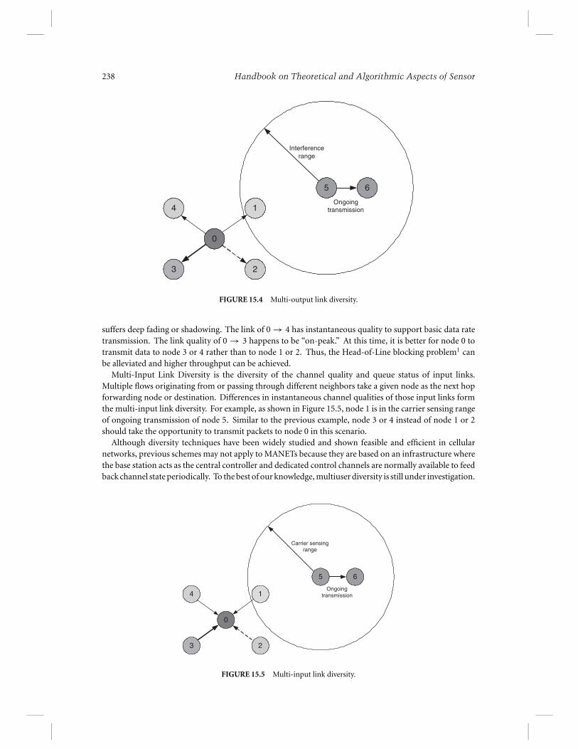
Multi-Output Link Diversity is the diversity of instantaneous channel quality and congestion status ofoutput links. Multiple flows may originate from or pass through a given node and take different neighborsas the next hop forwarding nodes or destinations. After this node acquires a transmission opportunity,it can choose a link with good instantaneous quality to transmit data in the given cycle. For example,as shown in Figure 15.4, node 1 is interfered by ongoing transmission of node 5 and the link of 0 → 2
238 Handbook on Theoretical and Algorithmic Aspects of Sensor
0
2
14
3
5 6
Ongoingtransmission
Interference range
FIGURE 15.4 Multi-output link diversity.
suffers deep fading or shadowing. The link of 0 → 4 has instantaneous quality to support basic data ratetransmission. The link quality of 0 → 3 happens to be “on-peak.” At this time, it is better for node 0 totransmit data to node 3 or 4 rather than to node 1 or 2. Thus, the Head-of-Line blocking problem1 canbe alleviated and higher throughput can be achieved.
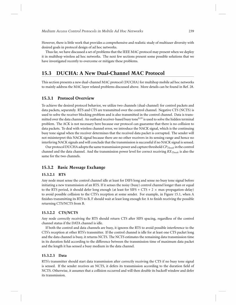
Multi-Input Link Diversity is the diversity of the channel quality and queue status of input links.Multiple flows originating from or passing through different neighbors take a given node as the next hopforwarding node or destination. Differences in instantaneous channel qualities of those input links formthe multi-input link diversity. For example, as shown in Figure 15.5, node 1 is in the carrier sensing rangeof ongoing transmission of node 5. Similar to the previous example, node 3 or 4 instead of node 1 or 2should take the opportunity to transmit packets to node 0 in this scenario.
Although diversity techniques have been widely studied and shown feasible and efficient in cellularnetworks, previous schemes may not apply to MANETs because they are based on an infrastructure wherethe base station acts as the central controller and dedicated control channels are normally available to feedback channel state periodically. To the best of our knowledge, multiuser diversity is still under investigation.
0
2
14
3
5 6
Ongoingtransmission
Carrier sensing range
FIGURE 15.5 Multi-input link diversity.
Medium Access Control Protocols in Mobile Ad Hoc Networks 239
However, there is little work that provides a comprehensive and realistic study of multiuser diversity withdesired goals in protocol design of ad hoc networks.
Thus far, we have discussed a set of problems that the IEEE MAC protocol may present when we deployit in multihop wireless ad hoc networks. The next few sections present some possible solutions that wehave investigated recently to overcome or mitigate these problems.
15.3 DUCHA: A New Dual-Channel MAC Protocol
This section presents a new dual-channel MAC protocol (DUCHA) for multihop mobile ad hoc networksto mainly address the MAC layer related problems discussed above. More details can be found in Ref. 28.
15.3.1 Protocol Overview
To achieve the desired protocol behavior, we utilize two channels (dual-channel) for control packets anddata packets, separately. RTS and CTS are transmitted over the control channel. Negative CTS (NCTS) isused to solve the receiver blocking problem and is also transmitted in the control channel. Data is trans-mitted over the data channel. An outband receiver-based busy tone9,19 is used to solve the hidden terminalproblem. The ACK is not necessary here because our protocol can guarantee that there is no collision todata packets. To deal with wireless channel error, we introduce the NACK signal, which is the continuingbusy tone signal when the receiver determines that the received data packet is corrupted. The sender willnot misinterpret this NACK signal because there are no other receivers in its sensing range and hence nointerfering NACK signals and will conclude that the transmission is successful if no NACK signal is sensed.
Our protocol DUCHA adopts the same transmission power and capture threshold CPThresh in the controlchannel and the data channel. And the transmission power level for correct receiving RXThresh is also thesame for the two channels.
15.3.2 Basic Message Exchange
15.3.2.1 RTS
Any node must sense the control channel idle at least for DIFS long and sense no busy tone signal beforeinitiating a new transmission of an RTS. If it senses the noisy (busy) control channel longer than or equalto the RTS period, it should defer long enough (at least for SIFS + CTS + 2 × max-propagation-delay)to avoid possible collision to the CTS’s reception at some sender. For example, in Figure 15.1, when Afinishes transmitting its RTS to B, F should wait at least long enough for A to finish receiving the possiblereturning CTS/NCTS from B.
15.3.2.2 CTS/NCTS
Any node correctly receiving the RTS should return CTS after SIFS spacing, regardless of the controlchannel status if the DATA channel is idle.
If both the control and data channels are busy, it ignores the RTS to avoid possible interference to theCTS’s reception at other RTS’s transmitter. If the control channel is idle for at least one CTS packet longand the data channel is busy, it returns NCTS. The NCTS estimates the remaining data transmission timein its duration field according to the difference between the transmission time of maximum data packetand the length it has sensed a busy medium in the data channel.
15.3.2.3 Data
RTS’s transmitter should start data transmission after correctly receiving the CTS if no busy tone signalis sensed. If the sender receives an NCTS, it defers its transmission according to the duration field ofNCTS. Otherwise, it assumes that a collision occurred and will then double its backoff window and deferits transmission.
240 Handbook on Theoretical and Algorithmic Aspects of Sensor
15.3.2.4 Busy Tone
The intended receiver begins to sense the data channel after it transmits CTS. If the receiver does notreceive a signal with enough power in the data channel in the due time that the first few bits of the datapacket reaches it, it will assume that the sender does not transmit data and finish the receiving procedure.Otherwise, it transmits a busy tone signal to prevent possible transmissions from hidden terminals.
15.3.2.5 NACK
The intended receiver has a timer to indicate when it should finish the reception of the data packet accordingto the duration field in the previously received RTS. If the timer expires and has not received the correctdata packet, it assumes that the data transmission fails and sends NACK by continuing the busy tone signalfor an appropriate time period. If it correctly receives the data packet, it stops the busy tone signal andfinishes the receiving procedure.
The sender assumes that its data transmission is successful if there is no NACK signal sensed over thebusy tone channel during the NACK period. Otherwise, it assumes that its transmission fails because ofwireless channel error and then starts the retransmission procedure.
In addition, during the NACK period, in addition to the data transmission period, any other nodes inthe sensing range of the sender are not allowed to become the receiver of data packets, and any other nodesin the sensing range of the receiver are not allowed to become the sender of data packets. This is to avoidconfusion between NACK signals and the normal busy tone signals.
In the above message exchange, our protocol transmits or receives packets in only one channel at anytime. We only use receive busy tone signals and not transmit busy tone signals. Thus it is necessary tosense the data channel before transmitting CTS/NCTS packets to avoid becoming a receiver in the sensingrange of the transmitters of some ongoing data packet transmissions.
15.3.3 Solutions to the Aforementioned Problems
In the following discussions, we use examples to illustrate how our DUCHA solves those well-knowproblems.
15.3.3.1 Solution to the Hidden Terminal Problem
As shown in Figure 15.1, B broadcasts a busy tone signal when it receives a data packet from A. The hiddenterminal of A (i.e., D) could hear B’s busy tone signal and thus will not transmit in the data channel toavoid interference with B’s reception. Thus, the busy tone signal from the data’s receiver prevents anyhidden terminals of the intended sender from interfering with the reception. Moreover, no DATA packetsare dropped due to the hidden terminal problem.
15.3.3.2 Solution to the Exposed Terminal Problem
In Figure 15.1, B is the exposed terminal of D when D is transmitting a data packet to E. B could initiateRTS/CTS exchange with A although it can sense D’s transmission in the data channel. After the RTS/CTSexchange is successful between B and A, B begins to transmit the data packet to A. Because A is out ofthe sensing range of D and E is out of sensing range of B, both A and E could correctly receive the datapacket destined to them. Thus, the exposed terminal could transmit data packets in DUCHA, which couldimprove the spatial reuse ratio.
15.3.3.3 Solution to the Receiver Blocking Problem
In Figure 15.1, B is the blocked receiver in the IEEE 802.11 MAC protocol when D is transmitting datapackets to E. In our protocol DUCHA, B can correctly receive A’s RTS in the control channel while D sendsdata packets in the data channel. Then B returns the NCTS to A because it senses a busy medium in the DATAchannel. The duration field of NCTS estimates the remaining busy period in the data channel required tofinish D’s transmission. When A receives the NCTS, it defers its transmission and stops the unnecessary
Medium Access Control Protocols in Mobile Ad Hoc Networks 241
retransmissions. It retries the transmission after the period indicated in the duration field of NCTS. Oncethe RTS/CTS exchange is successful between A and B, A begins to transmit the data packet to B. B willcorrectly receive the data packet because there is no hidden terminal problem for receiving data packets.
15.3.3.4 Maximum Spatial Reuse
As discussed above, the exposed terminals could transmit data packets. Furthermore, in our protocol, thehidden terminal could receive data packets although it cannot transmit. In Figure 15.1, D is the hiddenterminal of A when A is transmitting the data packet to B. After the RTS/CTS exchange between E and Dis successful in the control channel, E can transmit data packets to D. Because D is out of A’s sensing rangeand B is out of E’s sensing range, both D and E can correctly receive the intended data packets. Thus,our protocol DUCHA can achieve maximum spatial reuse by allowing multiple transmitters or multiplereceivers in the sensing range of each other to communicate. At the same time, there are no collisionsfor data packets or for the NACK signals because there is only one transmitter in its intended receiver’ssensing range and only one receiver in its intended transmitter’s sensing range.
15.3.3.5 Inherent Mechanisms to Solve the Intra-flow Contention Problem
In our DUCHA protocol, the receiver of data packets have the highest priority to access the channel forthe next data transmission. When one node correctly receives a data packet, it could immediately startthe backoff procedure for the new transmission, while the upstream and downstream nodes in its sensingrange are prevented from transmitting data packets during the NACK period. In fact, this could achieveoptimum packet scheduling for chain topology and is similar for any single flow scenario.
For example, in Figure 15.2, node 1 has the highest priority to access the channel when it receives onepacket from node 0 and hence immediately forwards the packet to node 2. For the same reason, node 2immediately forwards the received packet to node 3. Then node 3 forwards the received packet to node 4.Because node 0 can sense node 1 and 2’s transmissions, it will not interfere with these two nodes. Node0 cannot send packets to node 1 when node 3 forwards packet to 4 because node 1 is in the interferencerange of node 3. When node 4 forwards packet to node 5, node 0 may have the chance to send a packet tonode 1. In general, nodes that are four hops away from each other along the path could simultaneouslysend packets to their next hops. Thus, the procedure could utilize 1/4 of the channel bandwidth, themaximum throughput that can be approached by the chain topology.15
15.3.4 Bandwidth Allocation
We split the whole bandwidth into control and data channels. While the nodes are negotiating thetransmission by RTS and CTS in the control channel, there is no transmission in the data channel for thesenodes. On the other hand, when the nodes are transmitting data packets in data channel, the bandwidth inthe control channel is not fully utilized. There exists an optimal bandwidth allocation for the two channelsto reach the maximum throughput.
For simplicity of analysis, we assume that there are no collisions to all the packets, and the spacingsbetween RTS, CTS, and data are fixed and can be neglected when compared to the control and data frames.The maximum throughput is determined by the packet length and the data rate of each channel. LetL R , L C , and L D be lengths of RTS, CTS, and DATA, respectively; Rc and Rd be data rates of controland data channels, respectively; and BW be the total data rate (bandwdith). We observe that maximizingthroughput is equivalent to minimizing the total time for a successful transmission of a packet, say, Tp .Thus, the problem is to minimize Tp under the condition Rc + Rd = B W. We can easily obtain
Tp = L R + L C
Rc+ L D
Rd≥ (
√L R + L C + √
L D)2
Rc + Rd
(15.1)
Tp = (√
L R + L C + √L D)2
B W, when
Rc
Rd=
√L R + L C√
L D
242 Handbook on Theoretical and Algorithmic Aspects of Sensor
In IEEE 802.11, the total time for successful packet transmission when there is no transmission error (dueto collisions or channel condition) is
T ′p = L R + L C + L D
B W. (15.2)
We can observe that the bandwidth splitting sacrifices bandwidth utilization (Tp > T ′p). However,
our protocol can eliminate the collisions to data packets and greatly improve spatial reuse, leading toperformance improvement for multihop ad hoc networks.
15.4 Distributed Flow Control and Medium Access Control
This section proposes a scheme to address flow level related issues by optimizing the cross-layer interactionbetween the MAC layer and the higher layer. More details can be found in Refs. 26 and 27.
15.4.1 Motivation
Considering the fact that contentions are from the transmission attempts of packets at different nodes,which are generated by various traffic flows, it is natural to exploit flow control to schedule the packettransmissions to reduce the collisions and congestion at the MAC layer. The intuitive solution is to allowthe downstream nodes and the congested ones to transmit packets while keeping others silent, and hencesmoothly forward each packet to the destination without encountering severe collisions or excessive delayat the forwarding nodes. This motivates us to develop our scheme presented in the next subsection.
15.4.2 Solution
We present a framework of flow control over the MAC layer and queue management to address thecollisions and congestion problem due to the intra-flow contention and inter-flow contention. Based on theframework, a multihop packet scheduling algorithm is incorporated into the IEEE 802.11 MAC protocol.The salient feature here is to generalize the optimum packet scheduling of chain topology, which allowsnodes four hops away to transmit simultaneously, to any traffic flows in general topology.
The framework includes multiple mechanisms. The fast relay assigns high priority of channel accessto the downstream nodes when they receives packets, which reduces a lot of intra-flow contentions. Thebackward-pressure congestion control gives transmission opportunity to the congested node and keeps itsupstream nodes silent. This could not only reduce excessive contentions in the congested area, but alsoquickly eliminate the congestion. It is also a quick method to notify the source to slow the sending ratedown by exploiting the RTS/CTS of the IEEE 802.11 MAC protocol. The receiver-initiated transmissionscheme uses a three-way handshake to resume the blocked flow at the upstream nodes when the congestionis cleared. It is a timely and economical approach with even less control overhead than the normal four-wayhandshake transmission in the IEEE 802.11 protocol. We discuss each of these mechanisms in detail inthe next subsections.
15.4.2.1 Rule 1: Assigning High Priority of the Channel Access to the Receiver
In each multihop flow, the intermediate node on the path needs to contend for the shared channel with theupstream nodes when forwarding the received packet to the next hop. One way to avoid the first few nodeson the path to inject more packets than the succeeding nodes can forward is to assign high priority of channelaccess to each node when it receives a packet. This can achieve better scheduling for the chain topology.
For example, in Figure 15.2, node 1 has the highest priority when it receives one packet from node 0and then forwards the packet to node 2. Node 2 immediately forwards the received packet from node 1and forwards it to node 3. It is the same for node 3, which immediately forwards the received packet tonode 4. Because node 0 can sense the transmissions of nodes 1 and 2, it will not interfere with these twonodes. Node 0 cannot send packets to node 1 when node 3 forwards packet to node 4 because node 1 isin the interference range of node 3. When node 4 forwards packet to node 5, node 0 may have chance
Medium Access Control Protocols in Mobile Ad Hoc Networks 243
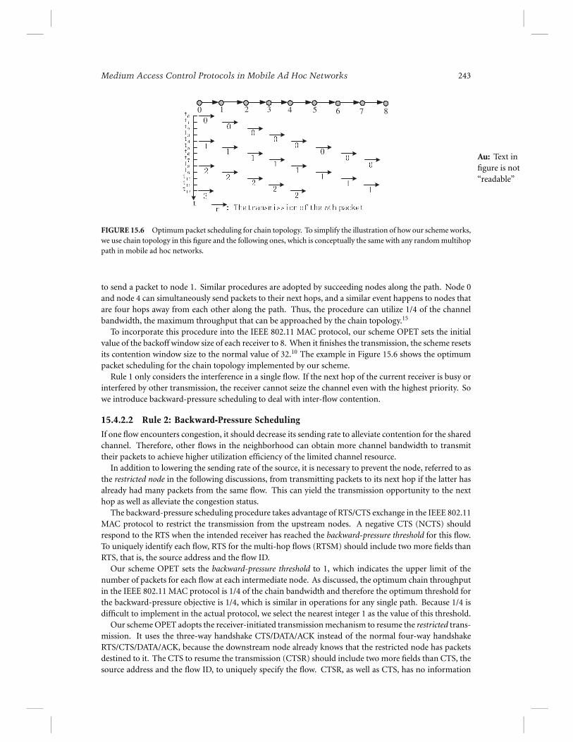
0 1 2 3 4 5 6 7 8
FIGURE 15.6 Optimum packet scheduling for chain topology. To simplify the illustration of how our scheme works,we use chain topology in this figure and the following ones, which is conceptually the same with any random multihoppath in mobile ad hoc networks.
to send a packet to node 1. Similar procedures are adopted by succeeding nodes along the path. Node 0and node 4 can simultaneously send packets to their next hops, and a similar event happens to nodes thatare four hops away from each other along the path. Thus, the procedure can utilize 1/4 of the channelbandwidth, the maximum throughput that can be approached by the chain topology.15
To incorporate this procedure into the IEEE 802.11 MAC protocol, our scheme OPET sets the initialvalue of the backoff window size of each receiver to 8. When it finishes the transmission, the scheme resetsits contention window size to the normal value of 32.10 The example in Figure 15.6 shows the optimumpacket scheduling for the chain topology implemented by our scheme.
Au: Text infigure is not“readable”
Rule 1 only considers the interference in a single flow. If the next hop of the current receiver is busy orinterfered by other transmission, the receiver cannot seize the channel even with the highest priority. Sowe introduce backward-pressure scheduling to deal with inter-flow contention.
15.4.2.2 Rule 2: Backward-Pressure Scheduling
If one flow encounters congestion, it should decrease its sending rate to alleviate contention for the sharedchannel. Therefore, other flows in the neighborhood can obtain more channel bandwidth to transmittheir packets to achieve higher utilization efficiency of the limited channel resource.
In addition to lowering the sending rate of the source, it is necessary to prevent the node, referred to asthe restricted node in the following discussions, from transmitting packets to its next hop if the latter hasalready had many packets from the same flow. This can yield the transmission opportunity to the nexthop as well as alleviate the congestion status.
The backward-pressure scheduling procedure takes advantage of RTS/CTS exchange in the IEEE 802.11MAC protocol to restrict the transmission from the upstream nodes. A negative CTS (NCTS) shouldrespond to the RTS when the intended receiver has reached the backward-pressure threshold for this flow.To uniquely identify each flow, RTS for the multi-hop flows (RTSM) should include two more fields thanRTS, that is, the source address and the flow ID.
Our scheme OPET sets the backward-pressure threshold to 1, which indicates the upper limit of thenumber of packets for each flow at each intermediate node. As discussed, the optimum chain throughputin the IEEE 802.11 MAC protocol is 1/4 of the chain bandwidth and therefore the optimum threshold forthe backward-pressure objective is 1/4, which is similar in operations for any single path. Because 1/4 isdifficult to implement in the actual protocol, we select the nearest integer 1 as the value of this threshold.
Our scheme OPET adopts the receiver-initiated transmission mechanism to resume the restricted trans-mission. It uses the three-way handshake CTS/DATA/ACK instead of the normal four-way handshakeRTS/CTS/DATA/ACK, because the downstream node already knows that the restricted node has packetsdestined to it. The CTS to resume the transmission (CTSR) should include two more fields than CTS, thesource address and the flow ID, to uniquely specify the flow. CTSR, as well as CTS, has no information
244 Handbook on Theoretical and Algorithmic Aspects of Sensor
RTSM
CTS
DATAACK
RTSM
NCTSCTSR
DATAACK
Non-last hop transmission
Blocktransmission
Resumetransmission
RTS
CTS
DATAACK
A A
Last hop transmission
B AB B BA
A: Transmitter; B: Receiver
FIGURE 15.7 Message sequence for packet transmission.
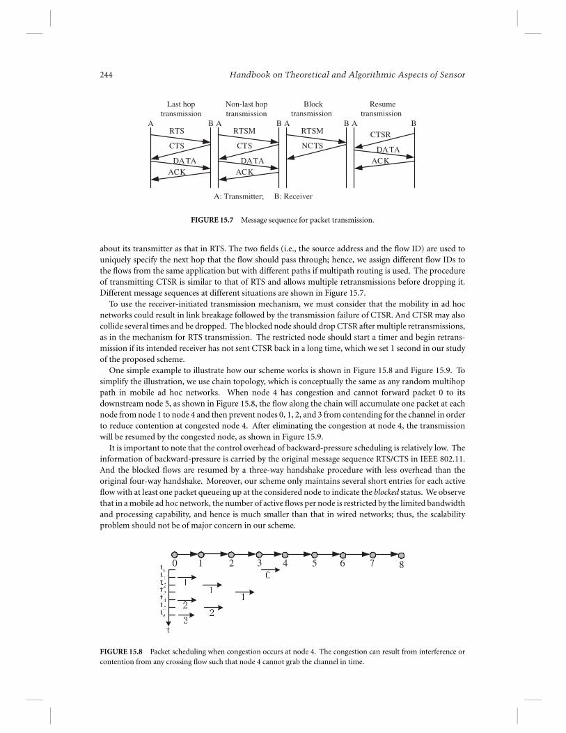
about its transmitter as that in RTS. The two fields (i.e., the source address and the flow ID) are used touniquely specify the next hop that the flow should pass through; hence, we assign different flow IDs tothe flows from the same application but with different paths if multipath routing is used. The procedureof transmitting CTSR is similar to that of RTS and allows multiple retransmissions before dropping it.Different message sequences at different situations are shown in Figure 15.7.
To use the receiver-initiated transmission mechanism, we must consider that the mobility in ad hocnetworks could result in link breakage followed by the transmission failure of CTSR. And CTSR may alsocollide several times and be dropped. The blocked node should drop CTSR after multiple retransmissions,as in the mechanism for RTS transmission. The restricted node should start a timer and begin retrans-mission if its intended receiver has not sent CTSR back in a long time, which we set 1 second in our studyof the proposed scheme.
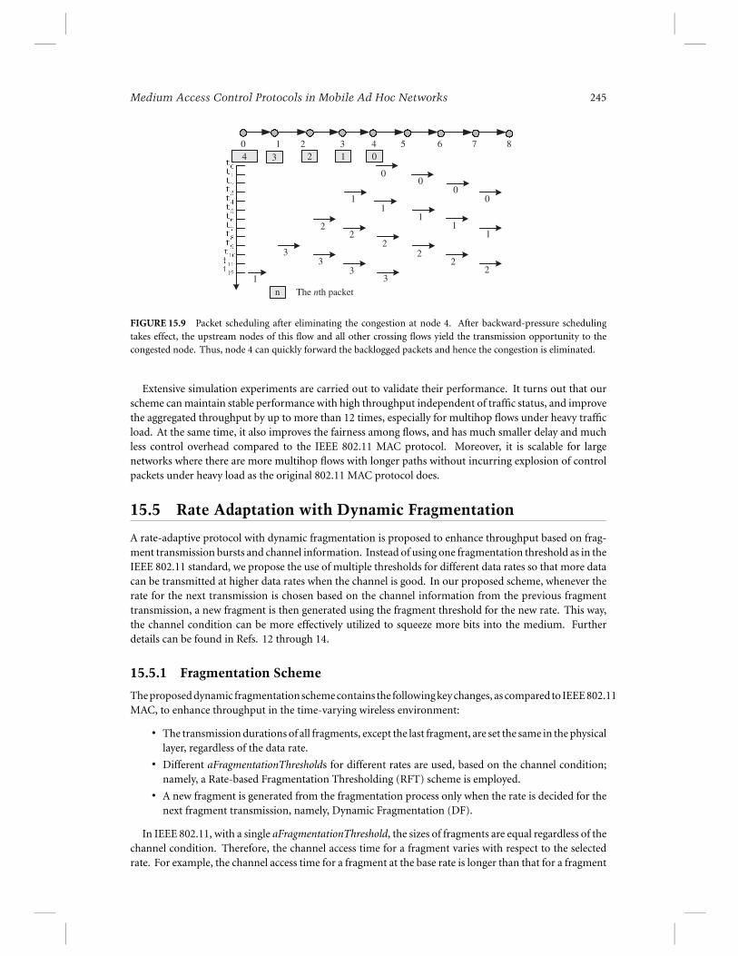
One simple example to illustrate how our scheme works is shown in Figure 15.8 and Figure 15.9. Tosimplify the illustration, we use chain topology, which is conceptually the same as any random multihoppath in mobile ad hoc networks. When node 4 has congestion and cannot forward packet 0 to itsdownstream node 5, as shown in Figure 15.8, the flow along the chain will accumulate one packet at eachnode from node 1 to node 4 and then prevent nodes 0, 1, 2, and 3 from contending for the channel in orderto reduce contention at congested node 4. After eliminating the congestion at node 4, the transmissionwill be resumed by the congested node, as shown in Figure 15.9.
It is important to note that the control overhead of backward-pressure scheduling is relatively low. Theinformation of backward-pressure is carried by the original message sequence RTS/CTS in IEEE 802.11.And the blocked flows are resumed by a three-way handshake procedure with less overhead than theoriginal four-way handshake. Moreover, our scheme only maintains several short entries for each activeflow with at least one packet queueing up at the considered node to indicate the blocked status. We observethat in a mobile ad hoc network, the number of active flows per node is restricted by the limited bandwidthand processing capability, and hence is much smaller than that in wired networks; thus, the scalabilityproblem should not be of major concern in our scheme.
0 1 2 3 4 5 6 7 8
FIGURE 15.8 Packet scheduling when congestion occurs at node 4. The congestion can result from interference orcontention from any crossing flow such that node 4 cannot grab the channel in time.
Medium Access Control Protocols in Mobile Ad Hoc Networks 245
0 1 2 3 4 5 6 7 84 3 2 1 0
00
001
11
11
22
22
22
33
33
n1
The nth packet
FIGURE 15.9 Packet scheduling after eliminating the congestion at node 4. After backward-pressure schedulingtakes effect, the upstream nodes of this flow and all other crossing flows yield the transmission opportunity to thecongested node. Thus, node 4 can quickly forward the backlogged packets and hence the congestion is eliminated.
Extensive simulation experiments are carried out to validate their performance. It turns out that ourscheme can maintain stable performance with high throughput independent of traffic status, and improvethe aggregated throughput by up to more than 12 times, especially for multihop flows under heavy trafficload. At the same time, it also improves the fairness among flows, and has much smaller delay and muchless control overhead compared to the IEEE 802.11 MAC protocol. Moreover, it is scalable for largenetworks where there are more multihop flows with longer paths without incurring explosion of controlpackets under heavy load as the original 802.11 MAC protocol does.
15.5 Rate Adaptation with Dynamic Fragmentation
A rate-adaptive protocol with dynamic fragmentation is proposed to enhance throughput based on frag-ment transmission bursts and channel information. Instead of using one fragmentation threshold as in theIEEE 802.11 standard, we propose the use of multiple thresholds for different data rates so that more datacan be transmitted at higher data rates when the channel is good. In our proposed scheme, whenever therate for the next transmission is chosen based on the channel information from the previous fragmenttransmission, a new fragment is then generated using the fragment threshold for the new rate. This way,the channel condition can be more effectively utilized to squeeze more bits into the medium. Furtherdetails can be found in Refs. 12 through 14.
15.5.1 Fragmentation Scheme
The proposed dynamic fragmentation scheme contains the following key changes, as compared to IEEE 802.11MAC, to enhance throughput in the time-varying wireless environment:
� The transmission durations of all fragments, except the last fragment, are set the same in the physicallayer, regardless of the data rate.� Different aFragmentationThresholds for different rates are used, based on the channel condition;
namely, a Rate-based Fragmentation Thresholding (RFT) scheme is employed.� A new fragment is generated from the fragmentation process only when the rate is decided for the
next fragment transmission, namely, Dynamic Fragmentation (DF).
In IEEE 802.11, with a single aFragmentationThreshold, the sizes of fragments are equal regardless of thechannel condition. Therefore, the channel access time for a fragment varies with respect to the selectedrate. For example, the channel access time for a fragment at the base rate is longer than that for a fragment
246 Handbook on Theoretical and Algorithmic Aspects of Sensor
at a higher rate. It is generally assumed that the channel remains unchanged during the transmission ofa fragment at the base rate. Thus, more data frames can, in fact, be transmitted when a higher rate isused in the same duration provided that the SNR is high enough to support the higher rate. Due to thisobservation, the OAR protocol17 proposes a multi-packet transmission scheme. However, multi-packettransmission has a higher overhead because of additional MAC headers, PHY headers, preambles in dataand ACK, and SIFS idle times.
To overcome the shortcoming of multi-packet transmission, we fix the time duration of all data trans-missions except for the last fragment. To generate fragments with the same time duration in a physicallayer, the number of bits in a fragment should be varied based on the selected rate. Thus, it is necessary tohave different aFragmentationThresholds for different data rates selected by the receiver.
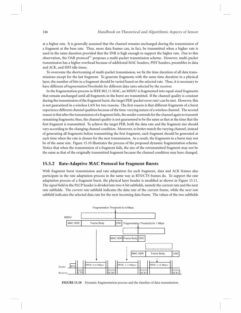
In the fragmentation process in IEEE 802.11 MAC, an MSDU is fragmented into equal-sized fragmentsthat remain unchanged until all fragments in the burst are transmitted. If the channel quality is constantduring the transmission of the fragment burst, the target PER (packet error rate) can be met. However, thisis not guaranteed in a wireless LAN for two reasons. The first reason is that different fragments of a burstexperience different channel qualities because of the time-varying nature of a wireless channel. The secondreason is that after the transmission of a fragment fails, the sender contends for the channel again to transmitremaining fragments; thus, the channel quality is not guaranteed to be the same as that at the time that thefirst fragment is transmitted. To achieve the target PER, both the data rate and the fragment size shouldvary according to the changing channel condition. Moreover, to better match the varying channel, insteadof generating all fragments before transmitting the first fragment, each fragment should be generated ateach time when the rate is chosen for the next transmission. As a result, the fragments in a burst may notbe of the same size. Figure 15.10 illustrates the process of the proposed dynamic fragmentation scheme.Notice that when the transmission of a fragment fails, the size of the retransmitted fragment may not bethe same as that of the originally transmitted fragment because the channel condition may have changed.
15.5.2 Rate-Adaptive MAC Protocol for Fragment Bursts
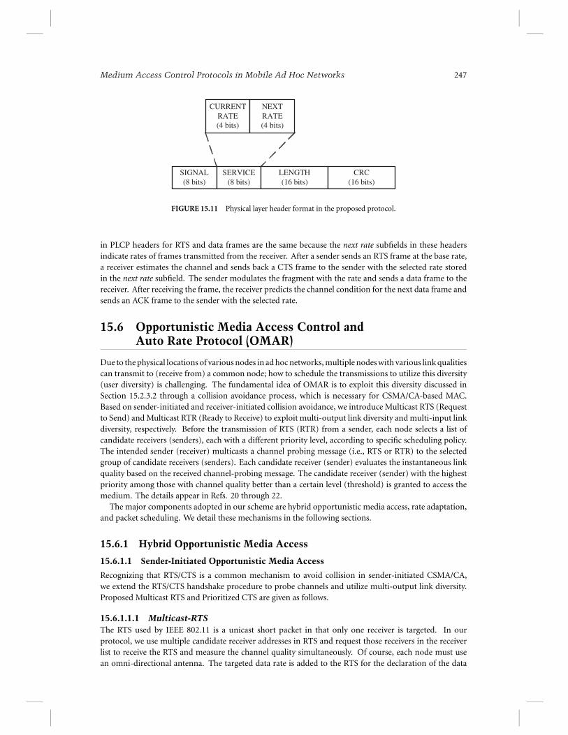
With fragment burst transmission and rate adaptation for each fragment, data and ACK frames alsoparticipate in the rate adaptation process in the same way as RTS/CTS frames do. To support the rateadaptation process of a fragment burst, the physical layer header is modified as shown in Figure 15.11.The signal field in the PLCP header is divided into two 4-bit subfields, namely the current rate and the nextrate subfields. The current rate subfield indicates the data rate of the current frame, while the next ratesubfield indicates the selected data rate for the next incoming data frame. The values of the two subfields
Frame BodyMAC HDR CRC
MSDU
Fragmentation Threshold for 6 Mbps
Frame BodyMAC HDR CRC
Frame BodyMAC HDR CRC
Fragmentation Threshold for 1 Mbps
RTS
CTS
PPDU 0 (6 Mbps)
ACK0 ACK1 ACK3
Sender
Receiver
PPDU 1 (1 Mbps) PPDU 2 (4 Mbps)
FIGURE 15.10 Dynamic fragmentation process and the timeline of data transmission.
Medium Access Control Protocols in Mobile Ad Hoc Networks 247
CURRENTRATE(4 bits)
NEXTRATE(4 bits)
SIGNAL(8 bits)
SERVICE(8 bits)
LENGTH(16 bits)
CRC(16 bits)
FIGURE 15.11 Physical layer header format in the proposed protocol.
in PLCP headers for RTS and data frames are the same because the next rate subfields in these headersindicate rates of frames transmitted from the receiver. After a sender sends an RTS frame at the base rate,a receiver estimates the channel and sends back a CTS frame to the sender with the selected rate storedin the next rate subfield. The sender modulates the fragment with the rate and sends a data frame to thereceiver. After receiving the frame, the receiver predicts the channel condition for the next data frame andsends an ACK frame to the sender with the selected rate.
15.6 Opportunistic Media Access Control andAuto Rate Protocol (OMAR)
Due to the physical locations of various nodes in ad hoc networks, multiple nodes with various link qualitiescan transmit to (receive from) a common node; how to schedule the transmissions to utilize this diversity(user diversity) is challenging. The fundamental idea of OMAR is to exploit this diversity discussed inSection 15.2.3.2 through a collision avoidance process, which is necessary for CSMA/CA-based MAC.Based on sender-initiated and receiver-initiated collision avoidance, we introduce Multicast RTS (Requestto Send) and Multicast RTR (Ready to Receive) to exploit multi-output link diversity and multi-input linkdiversity, respectively. Before the transmission of RTS (RTR) from a sender, each node selects a list ofcandidate receivers (senders), each with a different priority level, according to specific scheduling policy.The intended sender (receiver) multicasts a channel probing message (i.e., RTS or RTR) to the selectedgroup of candidate receivers (senders). Each candidate receiver (sender) evaluates the instantaneous linkquality based on the received channel-probing message. The candidate receiver (sender) with the highestpriority among those with channel quality better than a certain level (threshold) is granted to access themedium. The details appear in Refs. 20 through 22.
The major components adopted in our scheme are hybrid opportunistic media access, rate adaptation,and packet scheduling. We detail these mechanisms in the following sections.
15.6.1 Hybrid Opportunistic Media Access
15.6.1.1 Sender-Initiated Opportunistic Media Access
Recognizing that RTS/CTS is a common mechanism to avoid collision in sender-initiated CSMA/CA,we extend the RTS/CTS handshake procedure to probe channels and utilize multi-output link diversity.Proposed Multicast RTS and Prioritized CTS are given as follows.
15.6.1.1.1 Multicast-RTSThe RTS used by IEEE 802.11 is a unicast short packet in that only one receiver is targeted. In ourprotocol, we use multiple candidate receiver addresses in RTS and request those receivers in the receiverlist to receive the RTS and measure the channel quality simultaneously. Of course, each node must usean omni-directional antenna. The targeted data rate is added to the RTS for the declaration of the data
248 Handbook on Theoretical and Algorithmic Aspects of Sensor
rate that the sender wants to achieve at a given directed link. We dynamically set the targeted data rateaccording to recently measured channel conditions among those candidate receivers in the list. Each nodemonitors the transmissions of its neighbors and records the received power. In addition, considering thatboth MPDU size and data rate are variable, we use the packet size rather than the duration into RTS foreach candidate receiver so that the corresponding receiver can derive duration according to the selecteddata rate based on the channel condition.
Anyone except the candidate receiver that receives the MRTS should tentatively keep silent to avoidpossible collision before the sender receives the CTS. After the selected qualified receiver determines thetransmission duration and send back CTS, the sender sets the duration field accordingly in the MACheader of the data frame10 for the final NAV setting. The MAC header is sent at the basic rate so that alloverhearing nodes can decode.
15.6.1.1.2 Prioritized CTSThe candidate receivers evaluate the channel condition based on physical-layer analysis of the received RTSmessage. If the channel quality is better than a certain level and its NAV is zero, the given receiver is a goodcandidate. To avoid collision when there are two or more good candidates, different inter-frame spacings(IFSs) are employed according to the listing order of intended receivers in the RTS. For example, the IFSof the nth receiver equals to SIFS + (n − 1)∗Time s lot. The receiver with the shortest IFS among thosehaving the capability to receive data packet would reply CTS first. Because all candidate receivers are withinone-hop transmission range of the sender and the physical carrier sensing range is normally larger thantwo hops of transmission,15 the CTS may be powerful enough for all other qualified candidate receivers tohear or sense. Suppose that busy tone9,19 is available; it would further enhance the physical carrier sensingcapability. The intended receiver turns on the busy tone upon receiving the CTS; thus, those receivers thatdetect CTS or busy tone from other sources would yield the opportunity to the one transmitting CTS inthe first place; that is, the one with the good channel condition and the highest priority. The duration tobe advertised in the CTS is set to 2∗SIFS plus transmission time for DATA and ACK.
15.6.1.2 Receiver-Initiated Opportunistic Media Access
RTR, as discussed in the literature,2,8,18,23 is also a unicast packet. To reduce the control packets (i.e., RTRto probe channel and queue status, especially when the link condition changes significantly and/or eachcandidate sender has no packet with high probability when the receiver polls it), we propose to use theMulticast RTR to poll the candidate senders. A candidate sender list is included in the frame of MulticastRTR. The noise power level (dB) indicates the interference and power level at the receiver. Here we assumethat link gain is symmetric and RTR is sent at the default power level. The candidate receivers can derivelink gains according to the receiving power. By the link gain and nomic transmit power of DATA, the sendercan calculate the expected receiving power at the receiver. Finally, the candidate senders can determinethe average SINR with known interference power level.Au: define
SINR Upon hearing the RTR, the candidate senders estimate the channel gain. The idle candidate senderwith link gain better than certain level is allowed to access media. Similar to the sender-initiated strategy,IFS is employed to differentiate the media access priority of candidate senders. The IFS of the nth senderis equal to SIFS + (n − 1)∗Time slot. The sender with the highest priority among those having goodlink conditions transmits data first. Similar to sender-initiated opportunistic media access, we propose toincorporate busy tone to enhance carrier sensing, even if it is not necessary. Thus, other intended senderswould yield the opportunity to the one transmitting DATA first, that is, the one with the good channelcondition and the highest priority.
15.6.2 Rate Adaptation
According to the channel condition evaluated by the physical layer analysis of Multicast RTS or MulticastRTR, SINR is determined and the appropriate modulation scheme can be selected to efficiently use thechannel, as discussed in Section 15.5.
Medium Access Control Protocols in Mobile Ad Hoc Networks 249
15.6.3 Scheduling
Here we discuss how to determine the candidate receiver (sender) list, the MPDU size, and the targeteddata rate of each candidate directed link, which is closely related to QoS and energy efficiency. Consideringthat there are many constraints such as CPU and energy consumption for portable wireless device, oneof the crucial requirements for the scheduling algorithm is simplicity. Many scheduling algorithms inthe literature,4 such as Round Robin (RR) and Earliest Timestamp First (ETF), can be tailored to ourframework to achieve the desired goals. The scheduling policy in our simulation is based on the window-based weighted Round Robin. The targeted data rate is dynamically set using an algorithm similar toARF.11 A station is allowed to transmit multiple packets successively without contending for the mediaagain after accessing the channel, as long as the total access time does not exceed a certain limit. Wefollow the thought of OAR17 to grant channel access for multiple packets in proportion to the ratio of theachievable data rate over the basic rate so that the time-share fairness as in IEEE 802.11 can be assured.We show from our simulation study that both throughput and fairness can be significantly enhanced evenby this simple scheduling method. We believe that fairness, QoS, and energy consumption can be furtherenhanced by more advanced scheduling algorithms.
15.7 Conclusion
This chapter discussed several important issues in MAC protocol design in IEEE 802.11 wireless LANs andmobile ad hoc networks, including severe MAC layer contention and collision in multihop environments,traffic flow contention, rate adaptation with dynamic fragmentation, multiple-input link diversity, andmultiple-output link diversity. Then we proposed several novel schemes to address these issues, schemesthat can greatly improve the performance of wireless networks in terms of throughput, end-to-end delay,fairness, stability, and scalability.
Acknowldegment
The authors would like to extend their appreciation to Byungseo Kim and Jianfeng Wang for their helpduring the preparation of this chapter.
References
1. P. Bhagwat, P. Bhattacharya, A. Krishna, and S. K. Tripathi, Enhancing Throughput over WirelessLANs Using Channel State Dependent Packet Scheduling, in Proc. of INFOCOM’96, 1998. Au: 96 versus
1998?2. V. Bharghavan, A. Demers, S. Shenker, and L. Zhang, MACAW: A Media Access Protocol forWirelessLANs, in ACM SIGCOMM ’94.
3. J. Broch, D.A. Maltz, D.B. Johnson, Y. Hu, and J. Jetcheva, A Performance Comparison of MultihopWireless Ad Hoc Network Routing Protocols, in Proc. of the Fourth ACM International Conference onMobile Computing and Networking (MobiCom’98), pp. 85–97, Oct. 1998.
4. Y. Cao and V.O.K. Li, Scheduling Algorithms in Broad-Band Wireless Networks, in Proc. of the IEEE,89(1), January 2001.
5. K. Chen, Y. Xue, and K. Nahrstedt, On Setting TCP’s Congestion Window Limit in Mobile Ad HocNetworks, in Proc. of IEEE International Conference on Communications (ICC 2003), May 2003.
6. Y. Fang and A.B. McDonald, Cross-Layer Performance Effects of Path Coupling in Wireless Ad HocNetworks: Power and Throughput Implications of IEEE 802.11 MAC, in Proc. of 21st IEEE InternationalPerformance, Computing, and Communications Conference, April 2002.
7. Z. Fu, P. Zerfos, H. Luo, S. Lu, L. Zhang, and M. Gerla, The Impact of Multihop Wireless Channel onTCP Throughput and Loss, in Proc. IEEE INFOCOMM’2003, March 2003.
8. J.J. Garcia-Luna-Aceves and A. Tzamaloukas, Reversing the Collision-Avoidance Handshake inWireless Networks, Mobicom’99.
250 Handbook on Theoretical and Algorithmic Aspects of Sensor
9. Z.J. Haas and J. Deng, Dual Busy Tone Multiple Access (DBTMA) — A Multiple Access Control forAd Hoc Networks, IEEE Transactions on Communications, 50(6), 975–985, June 2002.
10. IEEE standard for Wireless LAN Medium Access Control (MAC) and Physical Layer (PHY) Specifications,ISO/IEC 8802-11: 1999(E), Aug. 1999.
11. A. Kamerman and L. Monteban, WaveLAN II: A High-Performance Wireless LAN for the UnlicensedBand, Bell Labs Technical Journal, 1997.
12. B. Kim, Y. Fang, T. Wong, and Y. Kwon, Throughput Enhancement through Dynamic Fragmentationin Wireless LANs, submitted for publication.
13. B. Kim, Y. Fang, and T.F. Wong, Rate-Adaptive MAC Protocol in High-Rate Personal Area Networks,in Proc. of IEEE Wireless Communications and Networking Conference 2004 (WCNC’04), Atlanta, GA,March 2004.
14. B. Kim, Y. Fang, T.F. Wong, and Y. Kwon, Dynamic Fragmentation Scheme for Rate-Adaptive Wire-less LANs, IEEE International Symposium on Personal, Indoor and Mobile Radio Communications(PIMRC’2003), Beijing, China, September 7–10, 2003.
15. J. Li, C. Blake, D.S.J. De Couto, H.I. Lee, and R. Morris, Capacity of Ad Hoc Wireless Network, in Proc.of ACM MobiCom 2001, July 2001.
16. C. Perkins, E.M. Royer, S.R. Das, and M.K. Marina, Performance Comparison of Two On-DemandRouting Protocols for Ad Hoc Networks, IEEE Personal Communications, pp. 16–28, Feb. 2001.
17. B. Sadeghi, V. Kanodia, A. Sabharwal, and E. Knightly, Opportunistic Media Access for MultirateAd Hoc Networks, in Proc. ACM MOBICOM’ 02, September 2002.
18. F. Talucci, M. Gerla, and L. Fratta, MACA-BI(MACA by invitation — A Receiver Oriented AccessProtocol for Wireless Multihop Networks, PIMRC’97.
19. F.A. Tobagi and L. Kleinrock, Packet Switching in Radio Channels. Part II- The Hidden TerminalProblem in Carrier Sense Multiple-Access and the Busy-Tone Solution, IEEE Trans. Commun., Vol.COM-23, pp. 1417–1433, Dec. 1975.
20. J. Wang, H. Zhai, and Y. Fang, OMAR: Utilizing Diversity in Wireless Ad Hoc Networks, submittedfor publication.
21. J. Wang, H. Zhai, Y. Fang, and M.C. Yuang, Opportunistic Media Access Control and Rate Adaptationfor Wireless Ad Hoc Networks, IEEE International Conference on Communications (ICC’04), Paris,France, June 2004.
22. J. Wang, H. Zhai, and Y. Fang, Opportunistic Packet Scheduling and Media Access Control for WirelessLANs and Multi-hop Ad Hoc Networks, in Proc. of IEEE Wireless Communications and NetworkingConference (WCNC’04), Atlanta, March 2004.
23. Y. Wang and J.J. Garcia-Luna-Aceves, A New Hybrid Channel Access Scheme for Ad Hoc Networks,ACM WINET, Vol. 10, No. 4, July 2004.
24. S. Wu, Y. Tseng, and J. Sheu, Intelligent Medium Access for Mobile Ad Hoc Networks with Busy Tonesand Power Control, IEEE Journal on Selected Areas in Communications, 18, 1647–1657, Sept. 2000.
25. S. Xu and T. Safadawi, Does the IEEE 802.11 MAC Protocol Work Well in Multihop Wireless Ad HocNetworks?, IEEE Communications Magazine, pp. 130–137, June 2001.
26. H. Zhai and Y. Fang, Distributed Flow Control and Medium Access in Multihop Ad Hoc Networks,submitted for publication.
27. H. Zhai, J. Wang, and Y. Fang, Distributed Packet Scheduling for Multihop Flows in Ad Hoc Networks,in Proc. of IEEE Wireless Communications and Networking Conference (WCNC’04), Atlanta, March 2004.
28. H. Zhai, J. Wang, and Y. Fang, DUCHA: A New Dual-Channel MAC Protocol for Multihop MobileAd Hoc Networks, submitted for publication.


![Xiyu Zhai Barnabas Pocz´ ´os arXiv:1810.02054v2 [cs.LG] 5](https://img.pdfslide.us/doc/110x75/61570557a097e25c7650310d/xiyu-zhai-barnabas-pocz-os-arxiv181002054v2-cslg-5-.jpg)