Embed Size (px)
Citation preview
Honeywell Process Solutions
ERX Electronic Pressure Recorder
User Manual
October 2010
V 1.04Honeywell
2 www.honeywell.com
Revisions 1.02 07/16/07 Changed item 780 text to 790, missed labeled item Edited item 792 description Change item 789 default to No 09/13/07 1.03 Add Audit Trail & Display list 2 for P3 Voltage monitoring 12/07/07
1.04 Honeywell 10/2010
3
Table of Contents Introduction....................................................................................................................... 5 Warranty ........................................................................................................................... 6 Intrinsic Safety for Hazardous Locations....................................................................... 6
Warning.......................................................................................................................... 7 Modes of Operations......................................................................................................... 7
Sample Mode ................................................................................................................. 7 Display List Mode.......................................................................................................... 7 Default Display Items and Live Enable....................................................................... 7 Serial Access Mode........................................................................................................ 8
Level 1 ......................................................................................................................... 8 Level 2 ......................................................................................................................... 8
Instrument Access ............................................................................................................. 9 How the ERX Recorder Works ....................................................................................... 9 Pressure System ................................................................................................................ 9 Temperature System....................................................................................................... 11 Sample Interval ............................................................................................................... 11
Sample Interval Battery Life................................................................................... 11 Log Interval ..................................................................................................................... 11 Audit Trail ....................................................................................................................... 12
Default Audit Trail Report Items .............................................................................. 12 Audit Trail Report Item 1-10.................................................................................. 12
Description of default Audit Trail items ................................................................... 12 Informational Display (LCD)......................................................................................... 14 Installation and Operation of the ERX Recorder ........................................................ 15
Function Check............................................................................................................ 15 Instrument Setup......................................................................................................... 16 Instrument Configuration .......................................................................................... 16
Pressure .................................................................................................................... 16 Site IDs ......................................................................................................................... 16
Using MasterLink32 Software:...................................................................................... 17 • Date and Time ........................................................................................................... 17 • Sample Interval ......................................................................................................... 17 • Log Interval ............................................................................................................... 17 • Start-of-Gas Day ....................................................................................................... 17
• Alarm Limits ................................................................................................................. 17 2-Point Pressure Calibration (Defined)......................................................................... 18 2-Point Pressure Calibration (Gauge Transducers) .................................................... 18 2-point pressure calibration (procedure)...................................................................... 18 Two-Point Pressure Calibration (Absolute Transducers)........................................... 19
Two-point pressure calibration (items required) ..................................................... 20 Two-point pressure calibration (procedure - absolute) ........................................... 20
Two-Point Temperature Calibration ............................................................................ 22 Alarm Pulses (Form-A) .................................................................................................. 23 Output Pulse Specifications............................................................................................ 23 Communicating to the ERX Recorder with a Modem ................................................ 24
Internal Modem Communications............................................................................. 24
4 www.honeywell.com
External Modem Communications without an External RS-232 Case Connector25 Internal or External Communications with a RS-232 Case Connector ................. 25
Automatic Call-In Feature ............................................................................................. 26 Alarm Call-In .................................................................................................................. 26 Pulse Method ................................................................................................................... 26 AT Commands Method .................................................................................................. 27 Scheduled Call-In Method.............................................................................................. 27 Alarm and Scheduled Call-In ........................................................................................ 28 Modem Power Control--Call-out Window ................................................................... 28
30-Minute Window Interval ....................................................................................... 29 4-Hour Window Interval ............................................................................................ 29 Multiple Windows- within the start and ending interval ........................................ 29
Digi-Span Fuel Switching Feature................................................................................. 31 Firmware Upgrade.......................................................................................................... 32 Procedure to Upgrade ERX Recorder Firmware:....................................................... 32 Putting the ERX Recorder into “Shutdown” ............................................................... 35
Partial Shutdown......................................................................................................... 35 Complete Shutdown .................................................................................................... 35
Taking the ERX Recorder “Un-Configured”............................................................... 36 Software method: ........................................................................................................ 36 Hardware method--if serial link cannot be established ........................................... 37
Parameter Item List........................................................................................................ 38 Item Item Name & Description............................................................................... 38
P3 Pressure Coefficients....................................................................................... 38 Board Coefficients ................................................................................................... 38 P1 Pressure Coefficients................................................................................... 39 P2 Pressure Coefficients....................................................................................... 40 Board Coefficients ................................................................................................... 43
Audit Report Items-Default ........................................................................................... 53 Pressure only default Audit Trail .............................................................................. 53
P3 Pressure Coefficients 1-26 ................................................................................ 54 ERX Hazardous and Non-Hazardous Installation Drawings ..................................... 67

5
Available Soon…. Introduction Mercury Instruments ERX is a microprocessor-based, stand-alone, self-powered data recorder that measures gas pressure(s), gas temperature, case temperature, and applied power supplies. Sampled measurements, logged Audit Trail data, alarms, and operating parameters are stored in non-volatile memory and may be retrieved directly with a laptop computer, Palm Pilot, Pocket PC, or remotely via modem. Pressure and Temperature, alarms, and other sampled parameters may be displayed on an optional internal or external Alpha-Numeric LCD (Liquid Crystal Display). ERX Recorder is capable of sampling and recording up to three pressure transducers and ambient and gas temperatures. At the time of manufacturing, the ERX may be fabricated as a wall-mounted, pipe stand, or as a portable unit in an 800 series case, (three pressure default case) ERX Recorder (single pressure) or a Mini-AT (dual pressure) case. Calibrating and serial accessing an ERX Recorder is accomplished by using Mercury Instruments’ MasterLink32 version 3.50 or greater, Palm Suite, or Pocket PC software.
6 www.honeywell.com
MasterLink32 is a Window multifunctional software program that’s used to interface with an ERX Recorder, via a serial cable, modem, or Bluetooth device. MasterLink32 provides the following functions: • Instrument configuration • Date & Time • Alarm limits • Sample interval • Log interval • Audit Trail items (4 or 10 items) • Display list (up to 18 displayable items) • Units of measurement • Pressure(s) and Temperature calibration • Graph live pressure(s) or temperature • Graph historical data retrieved for the ERX Recorder • Audit Trail reports • Serial Communications • File management • Instrument security • See MasterLink32 ‘Help’ for additional functions and features Warranty Mercury instruments, Inc. warrants all instruments covered by this manual to be free from defects in material and workmanship under normal use and service of this product. If returned to our factory, transportation charges prepaid, within 4 years of the original purchase shipment date, Mercury Instruments agrees to repair or replace any instrument, which its examination reveals to have been defective due to faulty workmanship or material. All obligations or liabilities on Mercury Instruments part is to repair or replace warranty instruments, and does not include any other type of claims or damages, including but not limited to consequential damages following the use of misuse of instruments sold by it. Mercury Instruments reserves the rights, at any time, to make changes, modifications or enhancements to this product without prior notification. This warranty is in lieu of all other warranties, express or implied. No agent is authorized to assume for Mercury Instruments any liability except as set forth above Intrinsic Safety for Hazardous Locations Underwriter’s laboratories (UL) has listed the ERX Recorder as intrinsically safe for use in Class I, Division 1, Group D hazardous locations and Canadian Standards Associations (CSA) for use in Glass I, Division 1, Groups C & D hazardous locations. The ERX Recorder is recognized as intrinsically safe instrument when installed in accordance with UL control drawing 40-3332 or CSA control drawing 40-3332-A (see appendix).
7
Warning Use only Mercury Instruments manufactured battery packs with part numbers as specified on the certification label or control drawing. Use of third-party battery packs voids product warranty, voids intrinsic safety certifications and may impair safety. Modes of Operations The ERX Recorder is in one of three operating modes. Each mode is well defined and suited to a particular purpose. Operating Modes: • Sample • Display list • Serial
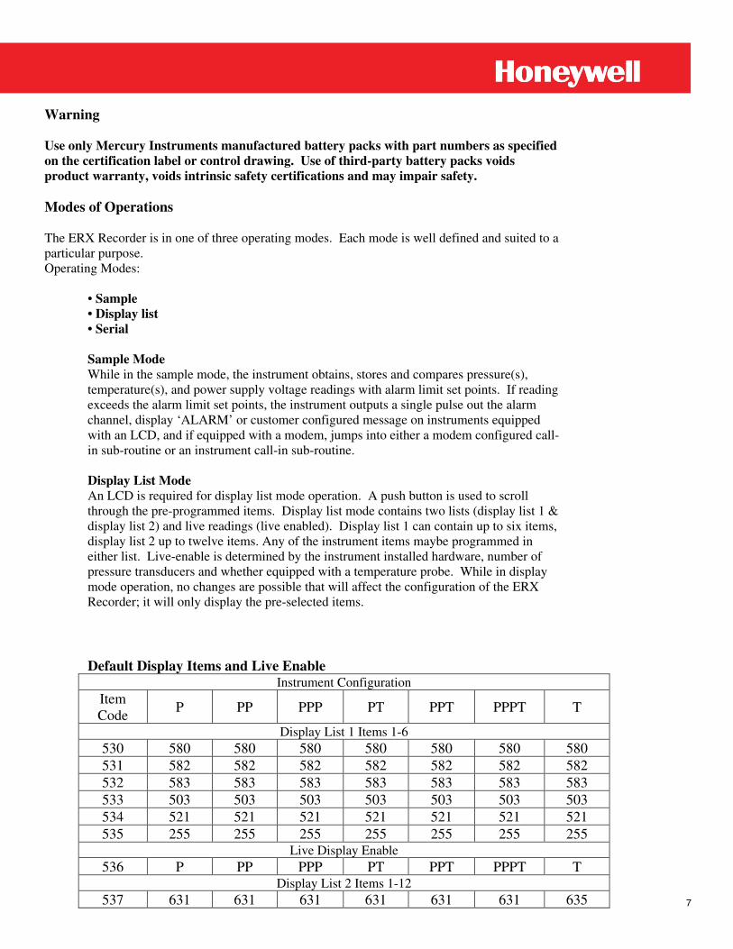
Sample Mode While in the sample mode, the instrument obtains, stores and compares pressure(s), temperature(s), and power supply voltage readings with alarm limit set points. If reading exceeds the alarm limit set points, the instrument outputs a single pulse out the alarm channel, display ‘ALARM’ or customer configured message on instruments equipped with an LCD, and if equipped with a modem, jumps into either a modem configured call-in sub-routine or an instrument call-in sub-routine. Display List Mode An LCD is required for display list mode operation. A push button is used to scroll through the pre-programmed items. Display list mode contains two lists (display list 1 & display list 2) and live readings (live enabled). Display list 1 can contain up to six items, display list 2 up to twelve items. Any of the instrument items maybe programmed in either list. Live-enable is determined by the instrument installed hardware, number of pressure transducers and whether equipped with a temperature probe. While in display mode operation, no changes are possible that will affect the configuration of the ERX Recorder; it will only display the pre-selected items.
Default Display Items and Live Enable
Instrument Configuration Item Code P PP PPP PT PPT PPPT T
Display List 1 Items 1-6 530 580 580 580 580 580 580 580 531 582 582 582 582 582 582 582 532 583 583 583 583 583 583 583 533 503 503 503 503 503 503 503 534 521 521 521 521 521 521 521 535 255 255 255 255 255 255 255
Live Display Enable 536 P PP PPP PT PPT PPPT T
Display List 2 Items 1-12 537 631 631 631 631 631 631 635
8 www.honeywell.com
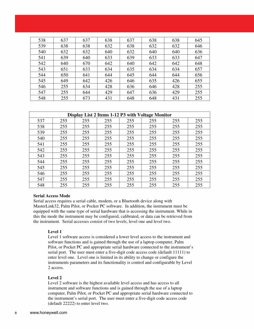
538 637 637 638 637 638 638 645 539 638 638 632 638 632 632 646 540 632 632 640 632 640 640 636 541 639 640 633 639 633 633 647 542 640 670 642 640 642 642 648 543 651 633 634 635 634 634 657 544 650 641 644 645 644 644 656 545 649 642 426 646 635 426 655 546 255 634 428 636 646 428 255 547 255 644 429 647 636 429 255 548 255 673 431 648 648 431 255
Display List 2 Items 1-12 P3 with Voltage Monitor 537 255 255 255 255 255 255 255 538 255 255 255 255 255 255 255 539 255 255 255 255 255 255 255 540 255 255 255 255 255 255 255 541 255 255 255 255 255 255 255 542 255 255 255 255 255 255 255 543 255 255 255 255 255 255 255 544 255 255 255 255 255 255 255 545 255 255 255 255 255 255 255 546 255 255 255 255 255 255 255 547 255 255 255 255 255 255 255 548 255 255 255 255 255 255 255
Serial Access Mode Serial access requires a serial cable, modem, or a Bluetooth device along with MasterLink32, Palm Pilot, or Pocket PC software. In addition, the instrument must be equipped with the same type of serial hardware that is accessing the instrument. While in this the mode the instrument may be configured, calibrated, or data can be retrieved from the instrument. Serial accesses consist of two levels, level one and level two.
Level 1 Level 1 software access is considered a lower level access to the instrument and software functions and is gained through the use of a laptop computer, Palm Pilot, or Pocket PC and appropriate serial hardware connected to the instrument’s serial port. The user must enter a five-digit code access code (default 11111) to enter level one. Level one is limited in its ability to change or configure the instruments parameters and its functionality is control and configurable by Level 2 access.
Level 2 Level 2 software is the highest available level access and has access to all instrument and software functions and is gained through the use of a laptop computer, Palm Pilot, or Pocket PC and appropriate serial hardware connected to the instrument’s serial port. The user must enter a five-digit code access code (default 22222) to enter level two.
9
Instrument Access In addition, an instrument access code is necessary to maintain the instrument security and must be entered or preprogrammed in appropriate software site list at the time of either successful level one or level two serial links. Instrument default access code: 33333 How the ERX Recorder Works The ERX Recorder utilizes a dedicated microprocessor in conjunction with precision sensors to measure gas pressure(s) and temperature(s) and records the measured values in memory. The electronic circuits are powered by a battery pack located inside of recorder case or by an external power source. The applied power regulated to voltages required by the connected circuits. While in the sample mode, most of the electronic circuitry is in an un-powered state (sleep mode) to conserve battery power. When an internal timer has reached the selected sample interval time, the electronics are energized and a sample measurement cycle begins. When the recorder wakes-up and enters the sample measurement mode, the programmable firmware instructs the microprocessor to obtain analog measurements. The analog signals (pressure(s), temperature(s) and power) are multiplexed through the A/D converter and routed to the microprocessor. The microprocessor converts and stores the digitized analog signals to an equivalent numeric value, scaled to the selected engineering units. P1 pressure is stored in item 500; P2 pressure is stored in item 501; P3 pressure is stored in item 420; Gas temperature is stored in item 502; Case temperature is stored in item 503: and power is stored in item 521. Once the all the measurements are obtained, the microprocessor compares the measured values to the parameter limits already in memory, i.e., high and low limits of pressure(s), temperature, power, etc; if any of the measured parameters are out-of-range, the firmware instructs the microprocessor to jump into an alarm subroutine. The alarm subroutine activates the appropriate alarm code item(s), turns on the alarm indicator, transmits an alarm pulse out the alarm channel and if equipped, activates a call-in, via a Messenger modem, CDMA…etc. If during a sample measurement cycle wake-up the power supply voltage falls below the low limit set points, the microprocessor activates the alarm indicator, transmits an alarm pulse out the alarm channel, and, if equipped, activates a modem call-in. After the microprocessor has completed the sample measurement cycle wake-up, the microprocessor will update memory, display the new samples data to the LCD, and return to the ‘sleep mode’ to conserve energy. Other than time, the ERX Recorder will also wake-up due to either a serial link or push button activation. A wake-up caused by a serial communication link allows the recorder to communicate with serial devices connected to J5 or through a COMS I/O port. A push button activation access will cause the microprocessor to initiate the display list mode, as described on page XXXXX. In all cases, the microprocessor will initiate a sample measurement cycle as described earlier and continue to energize most circuits while the recorder is performing the user-requested tasks. Pressure System (1 to 5000 PSI) The pressure-sensing system incorporates one, two or three precision strain gauge transducer. The transducers are housed in the ERX Recorder case and exit the case via 1/1” NPT female connector.

10 www.honeywell.com
Precision pressure transducers are characterized to 32 numeric points at the factory to determine offset, linearity, repeatability, and hysteresis. The 32 points of characterization are unique to each transducer and referred to as ‘Transducer Coefficients’. When replacing a transducer for any reason, the coefficients must be reloaded with the proper coefficients for the replacement transducer.
11
Temperature System -40 to 150 (-40 to 65C) The temperature system consists of a highly stable solid-state transducer connected to the ERX main circuit board through a 6-foot Teflon cable. The stainless steel probe is ¼” in diameter and six inches in length; however, longer or shorter probe lengths are available options as well as an armor cable. A ½” NPT nylon slip-along fitting is also provided for securing the temperature probe within the thermo well. The temperature probe assembly is universally interchangeable between ERX Recorders and electronic volume correctors. Sample Interval In the ERX Recorder sample-measurement mode applies power to the electronic circuit so the pressure(s), temperature(s), and power voltage measurements may be obtained. After obtaining new measurements, the item values and LCD are updated, and then compared to alarm limits, if the values exceed the alarm limit, the instrument will jump to alarm sub-routine. After completion of these tasks, the circuitry will return to the sleep mode of operation. Sample rates: 1, 5, 10, 30, and 60 seconds, default is 10 seconds Note: the faster the sample rate, the quicker battery powered instruments power is depleted.
Sample Interval Battery Life 1 second 1 year 10 seconds 3 years 60 seconds 4 years
Log Interval The log interval is a user-selectable item, its value determines how often Audit Trail report items are stored into the instrument’s memory. The choices are 1, 5, 10, 15, 30, 60, or 24 hours, 60 minutes as the default. At the selected time interval, the recorder will automatically enter a sample measurement wake-up cycle and store the user-defined Audit Trail report items into the instrument’s memory. The time-stamped record placed in memory will be identified with the log trigger “Time.” Hourly and daily time triggers will always occur at the top of the hour, at 00: 00: 00 zero minutes and seconds. For log triggers less than 60 minutes, time triggers will occur at 1, 5, 10, 15, or 30 minutes with zero seconds. Log triggers other than time will appear randomly and are placed in memory at the exact time the incident occurred.
12 www.honeywell.com
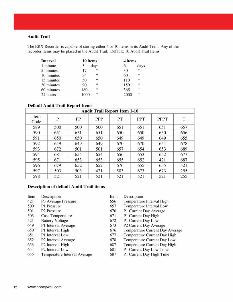
Audit Trail The ERX Recorder is capable of storing either 4 or 10 items in its Audit Trail. Any of the recorder items may be placed in the Audit Trail. Default: 10 Audit Trail Items
Interval 10 items 4 items 1 minute 3 days 6 days 5 minutes 17 “ 30 “ 10 minutes 34 “ 60 “ 15 minutes 50 “ 110 “ 30 minutes 90 “ 150 “ 60 minutes 180 “ 365 “ 24 hours 1000 “ 2000 “
Default Audit Trail Report Items
Audit Trail Report Item 1-10 Item Code P PP PPP PT PPT PPPT T
589 500 500 500 651 651 651 657 590 651 651 651 650 650 650 656 591 650 650 650 649 649 649 655 592 649 649 649 670 670 654 678 593 672 501 501 657 654 653 689 594 681 654 654 656 653 652 677 595 671 653 653 655 652 421 687 596 679 652 652 676 655 655 521 597 503 503 421 503 673 673 255 598 521 521 521 521 521 521 255
Description of default Audit Trail items Item Description Item Description 421 P3 Average Pressure 656 Temperature Interval High 500 P1 Pressure 657 Temperature Interval Low 501 P2 Pressure 670 P1 Current Day Average 503 Case Temperature 671 P1 Current Day High 521 Battery Voltage 672 P1 Current Day Low 649 P1 Interval Average 673 P2 Current Day Average 650 P1 Interval High 676 Temperature Current Day Average 651 P1 Interval Low 677 Temperature Current Day High 652 P2 Interval Average 678 Temperature Current Day Low 653 P2 Interval High 687 Temperature Current Day High 654 P2 Interval Low 681 P1 Current Day Low Time 655 Temperature Interval Average 687 P1 Current Day High Time
13
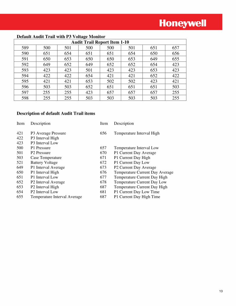
Default Audit Trail with P3 Voltage Monitor Audit Trail Report Item 1-10
589 500 501 500 500 501 651 657 590 651 654 651 651 654 650 656 591 650 653 650 650 653 649 655 592 649 652 649 652 652 654 423 593 423 423 501 423 423 653 423 594 422 422 654 421 421 652 422 595 421 421 653 502 502 423 421 596 503 503 652 651 651 651 503 597 255 255 423 657 657 657 255 598 255 255 503 503 503 503 255
Description of default Audit Trail items Item Description Item Description 421 P3 Average Pressure 656 Temperature Interval High 422 P3 Interval High 423 P3 Interval Low 500 P1 Pressure 657 Temperature Interval Low 501 P2 Pressure 670 P1 Current Day Average 503 Case Temperature 671 P1 Current Day High 521 Battery Voltage 672 P1 Current Day Low 649 P1 Interval Average 673 P2 Current Day Average 650 P1 Interval High 676 Temperature Current Day Average 651 P1 Interval Low 677 Temperature Current Day High 652 P2 Interval Average 678 Temperature Current Day Low 653 P2 Interval High 687 Temperature Current Day High 654 P2 Interval Low 681 P1 Current Day Low Time 655 Temperature Interval Average 687 P1 Current Day High Time
14 www.honeywell.com
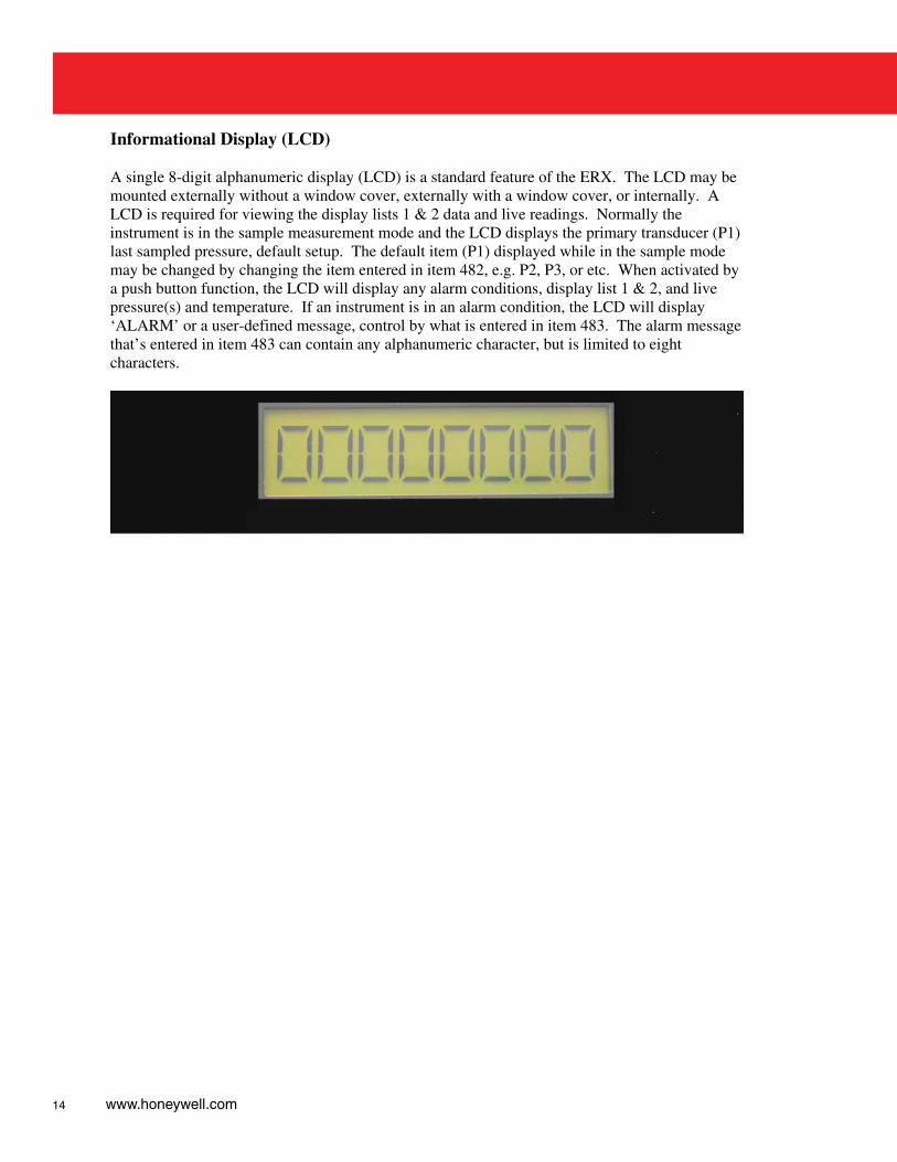
Informational Display (LCD) A single 8-digit alphanumeric display (LCD) is a standard feature of the ERX. The LCD may be mounted externally without a window cover, externally with a window cover, or internally. A LCD is required for viewing the display lists 1 & 2 data and live readings. Normally the instrument is in the sample measurement mode and the LCD displays the primary transducer (P1) last sampled pressure, default setup. The default item (P1) displayed while in the sample mode may be changed by changing the item entered in item 482, e.g. P2, P3, or etc. When activated by a push button function, the LCD will display any alarm conditions, display list 1 & 2, and live pressure(s) and temperature. If an instrument is in an alarm condition, the LCD will display ‘ALARM’ or a user-defined message, control by what is entered in item 483. The alarm message that’s entered in item 483 can contain any alphanumeric character, but is limited to eight characters.
15
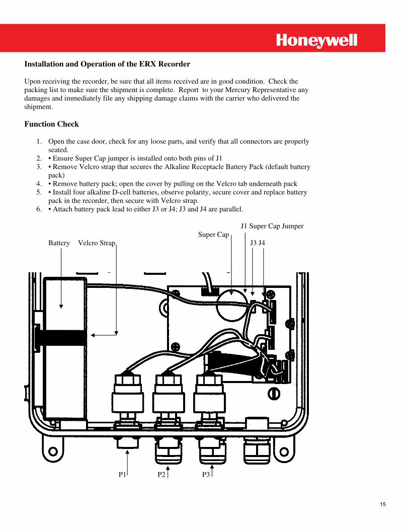
Installation and Operation of the ERX Recorder Upon receiving the recorder, be sure that all items received are in good condition. Check the packing list to make sure the shipment is complete. Report to your Mercury Representative any damages and immediately file any shipping damage claims with the carrier who delivered the shipment. Function Check
1. Open the case door, check for any loose parts, and verify that all connectors are properly seated.
2. • Ensure Super Cap jumper is installed onto both pins of J1 3. • Remove Velcro strap that secures the Alkaline Receptacle Battery Pack (default battery
pack) 4. • Remove battery pack; open the cover by pulling on the Velcro tab underneath pack 5. • Install four alkaline D-cell batteries, observe polarity, secure cover and replace battery
pack in the recorder, then secure with Velcro strap. 6. • Attach battery pack lead to either J3 or J4; J3 and J4 are parallel.
J1 Super Cap Jumper Super Cap
Battery Velcro Strap J3 J4
P1 P2 P3
16 www.honeywell.com
The LCD should display a pressure reading of close to ‘0.00. The recorder is now ready for functional checks.
*Note: All of the function checks assume that the instrument has been configured with a default setup.
Use the MI Logo (push button) or an optionally installed push button to scroll through the display list(s) and stop at the live pressure reading. Without having made a pressure connection, the LCD will display a value very close to zero, typically, within +/- 0.4% of full scale. Connect a pressure source to the external ¼” NPT pressure connector, apply a varying pressure (less than full scale) and observe an increase or decease in the LCD’s reading as the pressure varies. An automatic ten-minute time-out ensures that if a recorder left in a live reading, the recorder will return to the sample measurement mode to conserve battery power. Continue to scroll through the remaining display list items until the recorder has returned to the sample measurement mode. Instrument Setup The following items are critical in the recorder’s operation and proper configuration. Instrument Configuration Item 576 configures what the recorder will record, that is, pressure(s) and temperature data, if equipped, e.g. P, PP, PPP, PT, or PPPT. Pressure
Site IDs Site identification items 580 and 581, used to identify the recorder to the associated software. Items 580 and 581 Site IDs are preprogrammed using the recorder’s serial number, set by the factory prior to shipping, but may be changed to meet company’s requirement. Site IDs must remain unique, that is, no two recorders should have the same Site ID numbers.
Transducer Range
Xducer Range Unit Coefficients
Board Coefficients
Pressure (P1) 570 572 549 301~332 178~181 Pressure (P2) 571 573 550 341~372 441~444 Pressure (P3) 412 419 408 150~155 445~448 605~630 Temperature 551
17
Using MasterLink32 Software: • Date and Time Instrument Set Inst. Date/Time via computer, ensure date and time is correct in the computer before setting date and time via computer. Or Manually set time by entering the time in item 582 Manually set the date by entering the date in item 583 • Sample Interval Item 586 • Log Interval Item 585 • Start-of-Gas Day Item 587 • Alarm Limits Low Limit High Limit Low/Low High/High Pressure (P1) 554 553 814 813 Pressure (P2) 556 555 818 817 Pressure (P3) 452 451 808 807 Temperature 564 563 Battery 565
18 www.honeywell.com
2-Point Pressure Calibration (Defined) A 2-Point Pressure Calibration requires that two different pressures be applied to the instrument’s pressure transducer and be sampled by the data acquisition circuits. A low pressure value, usually 0.00 PSI, is applied to determine the Pressure Zero Calibration (offset). A higher pressure value is applied to determine the Pressure Span Calibration (gain). The default Calibration Parameters require that the Span Pressure exceeds the Zero Pressure by at least 50% of the transducer range, otherwise a “Points Too Close” error message is displayed. To produce a linear pressure response for all rated pressures and temperatures, each transducer has been factory characterized for ambient temperature effects. The characterization process determines the proper compensation coefficients for each transducer. The 2-point calibration process uses the coefficients when calculating the pressure offset and pressure span values. Once these two points have been calculated and stored in the instrument’s memory, all other applied pressures and temperature are automatically compensated by the coefficients. 2-Point Pressure Calibration (Gauge Transducers) 2-point pressure calibration (items required)
• ERX Recorder • Pressure source and fittings (capable of providing pressures of at least 50% of the ERX pressure transducer range) • Pressure Reference (accuracy to equal or exceed the accuracy of the ERX pressure system) • Computer (IBM Compatible) • MasterLink32 Software • I/O cable, part number 40-1629 and a MPA, part number 40-2620 or through the use of I/O cable, part number 40-1629 only if the instrument is equipped with an external case connector and a third option is through the use of I/O cable 40-2696 that connects directly to J5 on the main circuit board.
2-point pressure calibration (procedure) Make certain that the Pressure Compensation Coefficients listed are for the pressure transducer installed. Also verify that Item Code 087 is the desired pressure unit. Item Code 138 matches the transducer serial number label and item 112 is set for Gauge type transducer. Since the two-point calibration is mostly a software function, references to the appropriate sections in the MasterLink32 Link software are included. 1. Connect the pressure source and pressure reference to the ERX pressure connector. 2. Make a serial connect from the computer’s serial port to the ERX serial port. 3. Start MasterLink32 software on the computer. 4. Enter the access code for Level 1 or Level 2 when requested. The default Level 1 Access
Code is “11111”, the default Level 2 Access Code is “22222”. 5. If a communications link has not yet been established, the screen will display a box
requesting the user to input the Instrument Access Code. Enter the access code when this box appears. The default code is “33333”
19
6. Select “Calibrate” from the main menu. 7. Select “Pressure Calibration” from the sub-menu. 8. With zero pressure applied to the ERX pressure transducer, perform the “Pressure Zero
Calibration.” The pressure displayed in green on the computer’s screen is a live reading. This permits the user to determine if the pressure has stabilized so that a sample may be obtained. Click the AVERAGE PRESSURE NOW button when it becomes active (text changes from gray to black) to obtain a sample of the applied pressure.
9. When MasterLink32 displays “Average Pressure”, the value should be changed to match the pressure reference by clicking the CHANGE button when it becomes active. Enter the pressure value for the zero reference pressure (usually 0.00). The ERX will calculate the required difference offset, store this calculated value within the instrument before returning to a live pressure reading.
10. Compare the displayed pressure to the reference pressure. If the ERX pressure reading is not acceptable, click the AVERAGE PRESSURE NOW button again to obtain another pressure sample. The program will continue to loop back to the live pressure reading. Obtain as many pressure samples as necessary until an acceptable pressure reading is displayed.
11. If the ERX zero pressure reading is acceptable, click the SPAN button to change to the Span Calibration sequence.
12. The screen title should have changed to “Pressure Span Calibration.” At this point, the software is waiting to sample the applied pressure. Increase the pressure applied to the ERX to the span reference pressure. This must be greater than 50% of the transducer range.
Example #1: If the zero reference pressure on a 100 PSI transducer equals 0.00 PSI, then
the span reference pressure must be between 50.00 and 100.00 PSI. Example #2: If the zero reference pressure on a 600 PSI transducer equals 0.00 PSI, then
the span reference pressure must be between 300.00 and 600.00 PSI. 13. The span calibration also displays a live pressure reading to allow the user to determine if
the span reference pressure has stabilized. When the pressure has stabilized, click the AVERAGE PRESSURE NOW button when it becomes active to obtain a pressure sample.
14. If the average pressure reading is not equal to the span reference pressure, click the CHANGE button when it becomes active. Enter the pressure value for the span reference pressure. As the computer screen updates, the ERX will calculate the required span gain, store this calculated value within the instrument before returning to a live pressure reading. Obtain as many pressure samples as necessary until an acceptable span pressure reading is displayed.
15) Compare the average pressure reading to the span reference pressure. If the average pressure reading is acceptable, the pressure calibration process is complete. As a suggestion, recheck the pressure zero reading and any number of pressure points within the transducer range, or click DONE to exit the calibration sequence.
Two-Point Pressure Calibration (Absolute Transducers)
20 www.honeywell.com
Two-point pressure calibration (items required) • ERX • Pressure Source and fittings (capable of providing pressures of at least 50% of the ERX pressure transducer range) • Pressure Reference (accuracy to equal or exceed the accuracy of the ERX pressure system) • Computer (IBM Compatible) • I/O cable, part number 40-1629 and a MPA, part number 40-2620 or through the use of I/O cable, part number 40-1629 only if the instrument is equipped with an external case connector and a third option is through the use of I/O cable 40-2696 that connects directly to J5 on the main circuit board. • Barometer
Two-point pressure calibration (procedure - absolute) Make certain that the Pressure Compensation Coefficients loaded in the instrument are for the pressure transducer installed. Also verify that instrument is setup for the desired pressure unit. Since the two-point calibration is mostly a software function, references to the appropriate sections in the MasterLink32 software are included. 1. Connect the pressure source and pressure reference to the ERX pressure connector. 2. Make a serial connect from the computer’s serial port to the ERX serial port. 3. Start MasterLink32 software on the computer. 4. Enter the access code for Level 1 or Level 2 when requested. The default Level 1 Access
Code is “11111”, the default Level 2 Access Code is “22222”. 5. If a communications link has not yet been established, the screen will display a box
requesting the user to input the Instrument Access Code. Enter the access code when this box appears. The default code is “33333”.
6. Select “Calibrate” from the main menu. 7. Select “Pressure Calibration” from the sub-menu. 8. With zero pressure applied to the ERX pressure transducer, perform the “Pressure Zero
Calibration.” The pressure displayed in green on the computer’s screen is a live reading. This permits the user to determine if the pressure has stabilized so that a sample may be obtained. Click the AVERAGE PRESSURE NOW button when it becomes active (text changes from gray to black) to obtain a sample of the applied pressure.
9. Obtain the current local atmospheric pressure reading using a barometer or by some other means. When MasterLink32 displays “Average Pressure”, the value should be changed to match the current atmospheric pressure value by clicking the CHANGE button when it becomes active. Enter the current atmospheric pressure value, making sure the units are comparable, i.e., PSIA. The ERX will calculate the required difference offset, store this calculated value within the instrument before returning to a live absolute pressure reading.
10. Compare the displayed pressure to the reference pressure. If the ERX absolute pressure reading is not acceptable, click the AVERAGE PRESSURE NOW button again to obtain another pressure sample. The program will continue to loop back to the live pressure reading. Obtain as many pressure samples as necessary until an acceptable pressure reading is displayed.
11. If the ERX absolute pressure reading is acceptable, click the SPAN button to change to the Span Calibration sequence.
12. The screen title should have changed to “Pressure Span Calibration.” At this point, the software is waiting to sample the applied pressure. Increase the pressure applied to the ERX Recorder to the span reference pressure that exceeds the zero reference pressure by at least 50% of the rated transducer range.
21
Example #1: If the zero reference pressure on a 100 PSIA transducer equals 14.73 PSIA, then the span reference pressure must be between 64.73 and 100.00 PSI.
Example #2: If the zero reference pressure on a 100 PSIA transducer equals 13.25 PSIA,
then the span reference pressure must be between 63.25 and 100.00 PSI. Example #3: If the zero reference pressure on a 600 PSIA transducer equals 14.73 PSIA,
then the span reference pressure must be between 314.73 and 600.00 PSI. 13. The span calibration also displays a live pressure reading to allow the user to determine if
the span reference pressure has stabilized. When the absolute pressure has stabilized, click the AVERAGE PRESSURE NOW button when it becomes active to obtain a pressure sample.
NOTE: The span reference pressure is equal to the sum of the dead weight tester
pressure, and the atmospheric pressure obtained in step 9 above. 14. If the average pressure reading is not equal to the span reference pressure, click the
CHANGE button when it becomes active. Enter the pressure value for the span reference pressure. As the computer screen updates, the ERX will calculate the required span gain, and store this calculated value within the instrument before returning to a live pressure reading. Obtain as many pressure samples as necessary until an acceptable span pressure reading is displayed.
15. Compare the average, absolute pressure reading to the span reference pressure. If the average pressure reading is equal to the sum of the applied pressure plus the atmospheric pressure, the pressure calibration process is complete. As a suggestion, recheck the pressure zero reading and any number of pressure points within the transducer range, or click DONE to exit the calibration sequence.
22 www.honeywell.com
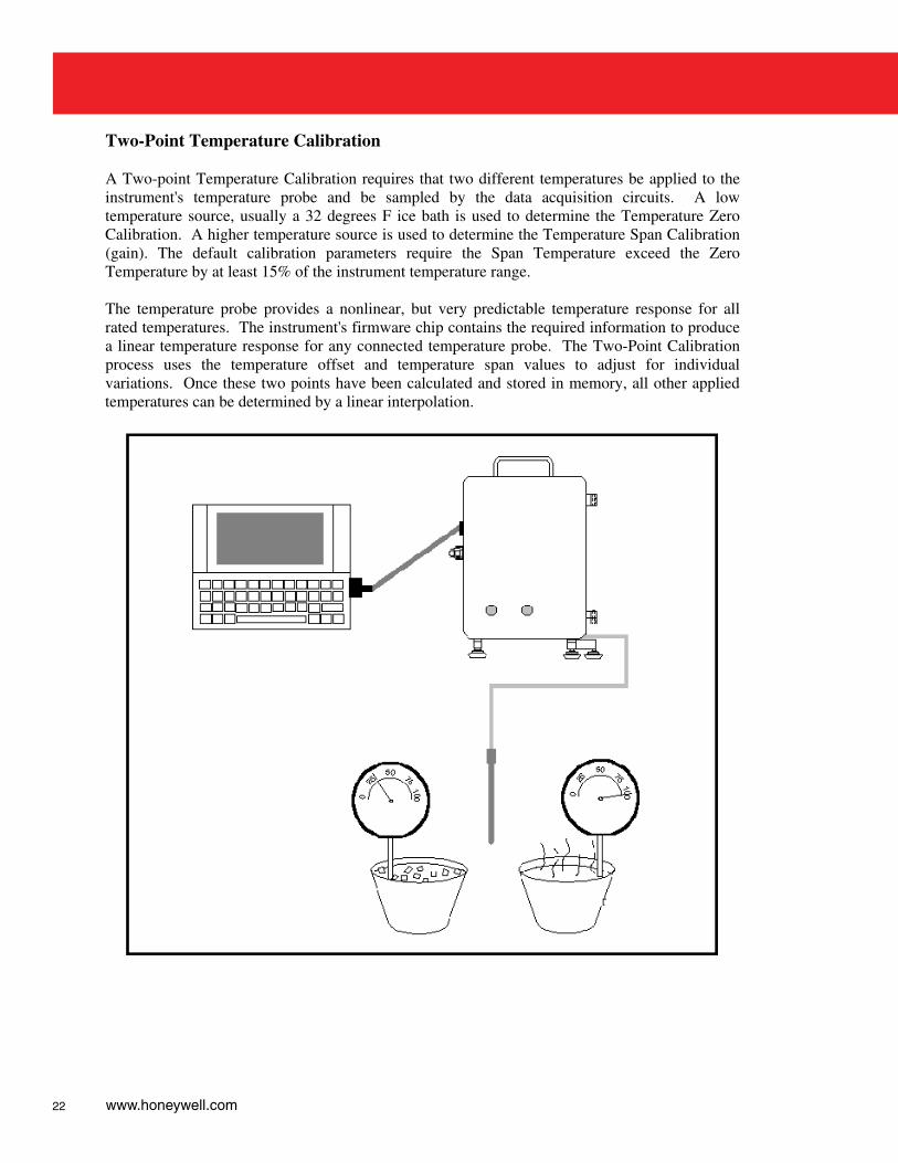
Two-Point Temperature Calibration A Two-point Temperature Calibration requires that two different temperatures be applied to the instrument's temperature probe and be sampled by the data acquisition circuits. A low temperature source, usually a 32 degrees F ice bath is used to determine the Temperature Zero Calibration. A higher temperature source is used to determine the Temperature Span Calibration (gain). The default calibration parameters require the Span Temperature exceed the Zero Temperature by at least 15% of the instrument temperature range. The temperature probe provides a nonlinear, but very predictable temperature response for all rated temperatures. The instrument's firmware chip contains the required information to produce a linear temperature response for any connected temperature probe. The Two-Point Calibration process uses the temperature offset and temperature span values to adjust for individual variations. Once these two points have been calculated and stored in memory, all other applied temperatures can be determined by a linear interpolation.
23
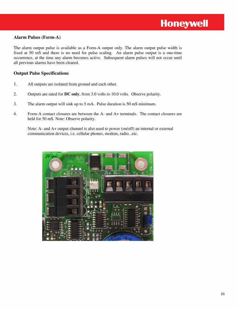
Alarm Pulses (Form-A) The alarm output pulse is available as a Form-A output only. The alarm output pulse width is fixed at 50 mS and there is no need for pulse scaling. An alarm pulse output is a one-time occurrence, at the time any alarm becomes active. Subsequent alarm pulses will not occur until all previous alarms have been cleared. Output Pulse Specifications 1. All outputs are isolated from ground and each other. 2. Outputs are rated for DC only, from 3.0 volts to 10.0 volts. Observe polarity. 3. The alarm output will sink up to 5 mA. Pulse duration is 50 mS minimum. 4. Form-A contact closures are between the A- and A+ terminals. The contact closures are
held for 50 mS. Note: Observe polarity.
Note: A- and A+ output channel is also used to power (on/off) an internal or external communication devices, i.e. cellular phones, modem, radio...etc.
24 www.honeywell.com
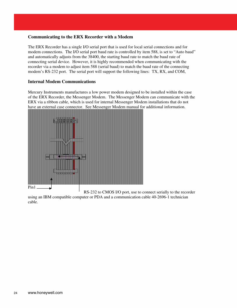
Communicating to the ERX Recorder with a Modem The ERX Recorder has a single I/O serial port that is used for local serial connections and for modem connections. The I/O serial port baud rate is controlled by item 588, is set to “Auto baud” and automatically adjusts from the 38400, the starting baud rate to match the baud rate of connecting serial device. However, it is highly recommended when communicating with the recorder via a modem to adjust item 588 (serial baud) to match the baud rate of the connecting modem’s RS-232 port. The serial port will support the following lines: TX, RX, and COM, Internal Modem Communications Mercury Instruments manufactures a low power modem designed to be installed within the case of the ERX Recorder, the Messenger Modem. The Messenger Modem can communicate with the ERX via a ribbon cable, which is used for internal Messenger Modem installations that do not have an external case connector. See Messenger Modem manual for additional information.
Pin1 RS-232 to CMOS I/O port, use to connect serially to the recorder using an IBM compatible computer or PDA and a communication cable 40-2696-1 technician cable.
25
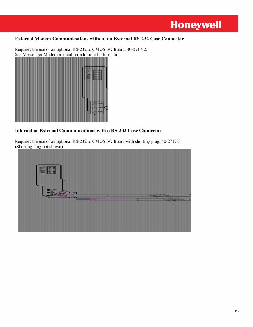
External Modem Communications without an External RS-232 Case Connector Requires the use of an optional RS-232 to CMOS I/O Board, 40-2717-2: See Messenger Modem manual for additional information.
Internal or External Communications with a RS-232 Case Connector Requires the use of an optional RS-232 to CMOS I/O Board with shorting plug, 40-2717-3: (Shorting plug not shown)
26 www.honeywell.com
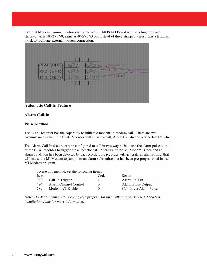
External Modem Communications with a RS-232 CMOS I/O Board with shorting plug and stripped wires, 40-2717-8, same as 40-2717-3 but instead of three stripped wires it has a terminal block to facilitate external modem connection.
Automatic Call-In Feature Alarm Call-In Pulse Method The ERX Recorder has the capability to initiate a modem-to-modem call. There are two circumstances where the ERX Recorder will initiate a call, Alarm Call-In and a Schedule Call-In. The Alarm Call-In feature can be configured to call in two ways: 1is to use the alarm pulse output of the ERX Recorder to trigger the automatic call-in feature of the MI Modem. Once and an alarm condition has been detected by the recorder, the recorder will generate an alarm pulse, that will cause the MI Modem to jump into an alarm subroutine that has been pre-programmed in the MI Modem program. To use this method, set the following items: Item Code Set to 333 Call-In Trigger 1 Alarm Call-In 484 Alarm Channel Control 0 Alarm Pulse Output 789 Modem AT Enable 0 Call-In via Alarm Pulse Note: The MI Modem must be configured properly for this method to work; see MI Modem installation guide for more information.
27
AT Commands Method The AT command method is accomplished by sending Hayes AT-type commands out the serial I/O port to a generic-type modem, such as the Messenger Modem. This method has the ERX recorder controlling the Hayes compatible modem. To use this method, set the following items: Item Code Set to 333 Call-In Trigger 1 Alarm Call-In only
789 Modem AT Enable 1 Call-In via AT commands
780 Modem Init String Initialization command of the Modem Default: ATE0Q0V0X4
781 Modem Dial String Command sent to indicate dialing Default: ATDT
782 Modem Hang-up String Command sent to modem for hang-up Default: ATH
784 Alarm Call-In Phone# Phone number to call due to an alarm
786 Modem Retry Interval A Time (minutes) between short-term retries
Default: 5 787 Modem Retry Interval B Time (minutes) to wait before trying again if all short-term retries have failed Default: 1440 788 Modem Retry Count A Number of short-term retries Default: 3 Scheduled Call-In Method The Scheduled Call-In feature requires the ERX Recorder to issue AT commands to a generic modem or to a Messenger modem. This feature, designed to interface with third party software applications that can accept a scheduled call-in from a remote site. To use this method, set the following items: Item Code Set to 333 Call-In Trigger 2 Scheduled Call-In only 334 Scheduled Call-In Date Date of call 335 Scheduled Call-In Time Time of call 339 Scheduled Call-In Phone # Phone number to call at schedule time 789 Modem AT Enable 1 Call-In via AT commands 780 Modem Init String Initialization command of the Modem Default: ATE0Q0V0X4 781 Modem Dial String Command sent to indicate dialing Default: ATDT 784 Alarm Call-In Phone# Phone number to call due to an alarm 782 Modem Hang-up String Command sent to modem for hang-up Default: ATH 786 Modem Retry Interval A Time (minutes) between short-term retries
28 www.honeywell.com
Default: 5 787 Modem Retry Interval B Time (minutes) to wait before trying again if all short-term retries have failed Default: 1440 788 Modem Retry Count A Number of short-term retries Note: Item 334 must be reset after a Scheduled Call-In; otherwise, the recorder will not call again. Alarm and Scheduled Call-In The ERX Recorder, if configured, can initialize a call-in due to an alarm and a scheduled-call-in. In this method, item 338 (Scheduled Call-In Occurred) may be used by the host system to determine whether the call-in was triggered by an alarm or due to a scheduled call-in. A scheduled call-in will have changed item 338 from ‘0’ to ‘1’ indicating that a scheduled call-in occurred and not an alarm. Item 338 must have its value reset to a value of ‘0’ and item 334 must be reset for the next scheduled call-in date after a Scheduled Call-In; otherwise, the recorder will not call again. To use this method, set the following items: Item Code Set to 333 Call-In Trigger 3 Alarm & Scheduled Call-In 334 Scheduled Call-In Date Date of call 335 Scheduled Call-In Time Time of call 339 Scheduled Call-In Phone # Phone number to call at schedule time 789 Modem AT Enable 1 Call-In via AT commands 780 Modem Init String Initialization command of the Modem Default: ATE0Q0V0X4 781 Modem Dial String Command sent to indicate dialing Default: ATDT 784 Alarm Call-In Phone# Phone number to call due to an alarm 782 Modem Hang-up String Command sent to modem for hang-up Default: ATH 786 Modem Retry Interval A Time (minutes) between short-term retries Default: 5 787 Modem Retry Interval B Time (minutes) to wait before trying again if all short-term retries have failed Default: 1440 788 Modem Retry Count A Number of short-term retries Modem Power Control--Call-out Window Modem power control is used to conserve battery power by only applying power to a communication device within an operating window when communication is desired. Modem power control utilizes the alarm output channel of TB1; A- and A+ to control the power applied to a communication device, such as, a modem, CDPD, or radio, etc. Item 484, Alarm-Channel-Control must be configured to Modem Power control instead of the default Alarm Pulse output. This action defeats Alarm Pulse output. The period that the communications device is powered is controled by item 791 Call-out Start Time and item 783 Call-out Stop Time and further defined by item 792 Call-out Repeat Interval and item 793 Call-out Keep Alive Time.
29
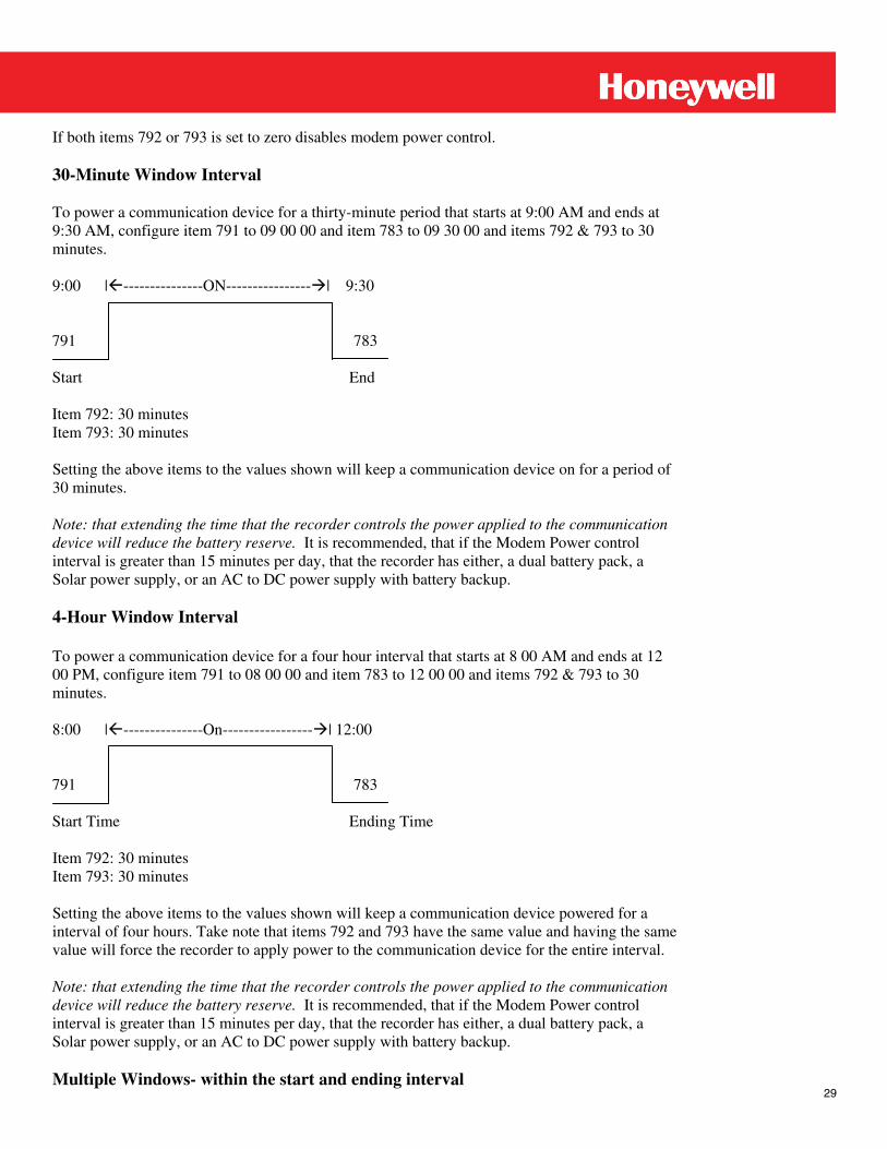
If both items 792 or 793 is set to zero disables modem power control. 30-Minute Window Interval To power a communication device for a thirty-minute period that starts at 9:00 AM and ends at 9:30 AM, configure item 791 to 09 00 00 and item 783 to 09 30 00 and items 792 & 793 to 30 minutes. 9:00 |---------------ON----------------| 9:30 791 783 Start End Item 792: 30 minutes Item 793: 30 minutes Setting the above items to the values shown will keep a communication device on for a period of 30 minutes. Note: that extending the time that the recorder controls the power applied to the communication device will reduce the battery reserve. It is recommended, that if the Modem Power control interval is greater than 15 minutes per day, that the recorder has either, a dual battery pack, a Solar power supply, or an AC to DC power supply with battery backup. 4-Hour Window Interval To power a communication device for a four hour interval that starts at 8 00 AM and ends at 12 00 PM, configure item 791 to 08 00 00 and item 783 to 12 00 00 and items 792 & 793 to 30 minutes. 8:00 |---------------On-----------------| 12:00 791 783 Start Time Ending Time Item 792: 30 minutes Item 793: 30 minutes Setting the above items to the values shown will keep a communication device powered for a interval of four hours. Take note that items 792 and 793 have the same value and having the same value will force the recorder to apply power to the communication device for the entire interval. Note: that extending the time that the recorder controls the power applied to the communication device will reduce the battery reserve. It is recommended, that if the Modem Power control interval is greater than 15 minutes per day, that the recorder has either, a dual battery pack, a Solar power supply, or an AC to DC power supply with battery backup. Multiple Windows- within the start and ending interval
30 www.honeywell.com
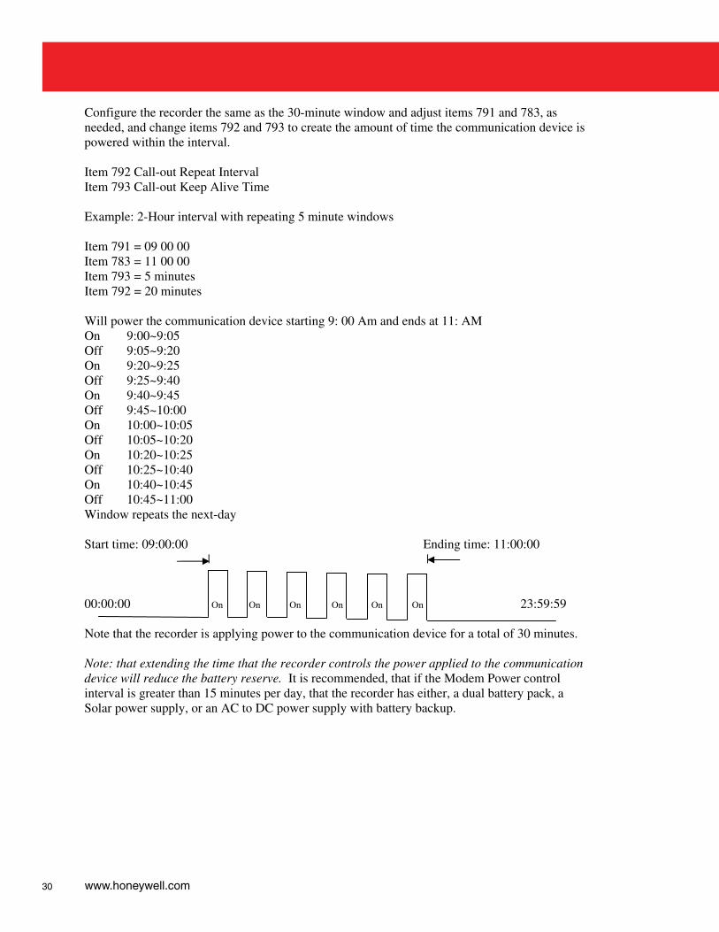
Configure the recorder the same as the 30-minute window and adjust items 791 and 783, as needed, and change items 792 and 793 to create the amount of time the communication device is powered within the interval. Item 792 Call-out Repeat Interval Item 793 Call-out Keep Alive Time Example: 2-Hour interval with repeating 5 minute windows Item 791 = 09 00 00 Item 783 = 11 00 00 Item 793 = 5 minutes Item 792 = 20 minutes Will power the communication device starting 9: 00 Am and ends at 11: AM On 9:00~9:05 Off 9:05~9:20 On 9:20~9:25 Off 9:25~9:40 On 9:40~9:45 Off 9:45~10:00 On 10:00~10:05 Off 10:05~10:20 On 10:20~10:25 Off 10:25~10:40 On 10:40~10:45 Off 10:45~11:00 Window repeats the next-day Start time: 09:00:00 Ending time: 11:00:00 | | 00:00:00 On On On On On On 23:59:59 Note that the recorder is applying power to the communication device for a total of 30 minutes. Note: that extending the time that the recorder controls the power applied to the communication device will reduce the battery reserve. It is recommended, that if the Modem Power control interval is greater than 15 minutes per day, that the recorder has either, a dual battery pack, a Solar power supply, or an AC to DC power supply with battery backup.
31
Digi-Span Fuel Switching Feature An ERX connected to a Digi-Span module provides an automatic or manual fuel switching function when item 340 is enabled. This feature requires ERX’s Pulser-A output to be connected to the Digi-Span’s “Gas Override” terminal, the Pulser-B output connected to the “Oil Override” terminal, and the common terminal ‘K’ connected to the Digi-Span common. When item code 340 is configured for Automatic mode, a pre-selected temperature at the Digi-Span module determines which fuel is ‘switched on’. Item 340 may also be configured for either a manual “Gas Override” or a manual “Oil Override”, which results in a continuous ON at one of the pulse outputs channels. Although not an original design consideration, there may be other applications that could make use of a continuous ON from either pulse output channel besides the Digi-Span module. Care must be taken to be certain that the connected device can be actuated with 5 mA of current, or less. Regardless of the connected device, enabling item 340 places a heavier burden on the battery, which will decrease battery life.
32 www.honeywell.com
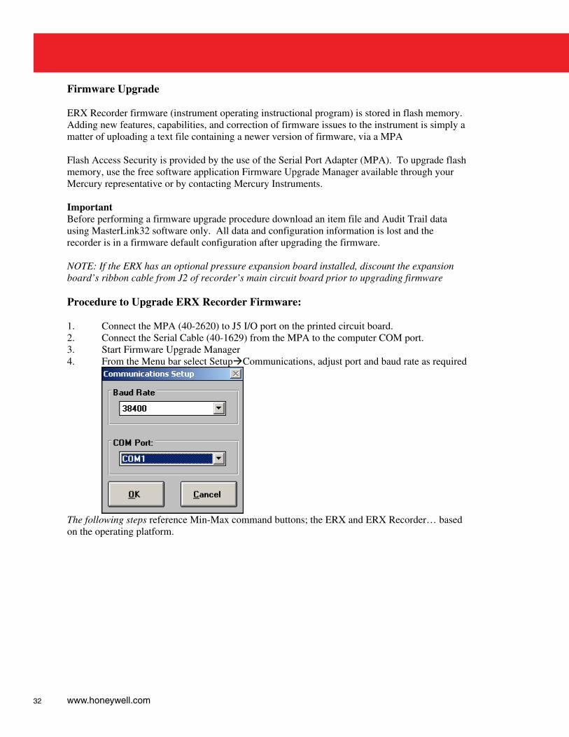
Firmware Upgrade ERX Recorder firmware (instrument operating instructional program) is stored in flash memory. Adding new features, capabilities, and correction of firmware issues to the instrument is simply a matter of uploading a text file containing a newer version of firmware, via a MPA Flash Access Security is provided by the use of the Serial Port Adapter (MPA). To upgrade flash memory, use the free software application Firmware Upgrade Manager available through your Mercury representative or by contacting Mercury Instruments. Important Before performing a firmware upgrade procedure download an item file and Audit Trail data using MasterLink32 software only. All data and configuration information is lost and the recorder is in a firmware default configuration after upgrading the firmware. NOTE: If the ERX has an optional pressure expansion board installed, discount the expansion board’s ribbon cable from J2 of recorder’s main circuit board prior to upgrading firmware Procedure to Upgrade ERX Recorder Firmware: 1. Connect the MPA (40-2620) to J5 I/O port on the printed circuit board. 2. Connect the Serial Cable (40-1629) from the MPA to the computer COM port. 3. Start Firmware Upgrade Manager 4. From the Menu bar select SetupCommunications, adjust port and baud rate as required
The following steps reference Min-Max command buttons; the ERX and ERX Recorder… based on the operating platform.
33
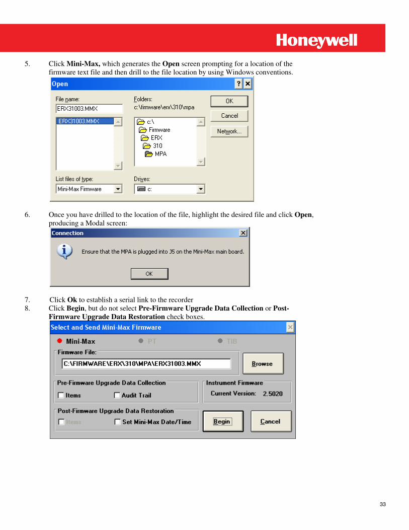
5. Click Mini-Max, which generates the Open screen prompting for a location of the
firmware text file and then drill to the file location by using Windows conventions.
6. Once you have drilled to the location of the file, highlight the desired file and click Open,
producing a Modal screen:
7. Click Ok to establish a serial link to the recorder 8. Click Begin, but do not select Pre-Firmware Upgrade Data Collection or Post-
Firmware Upgrade Data Restoration check boxes.
34 www.honeywell.com
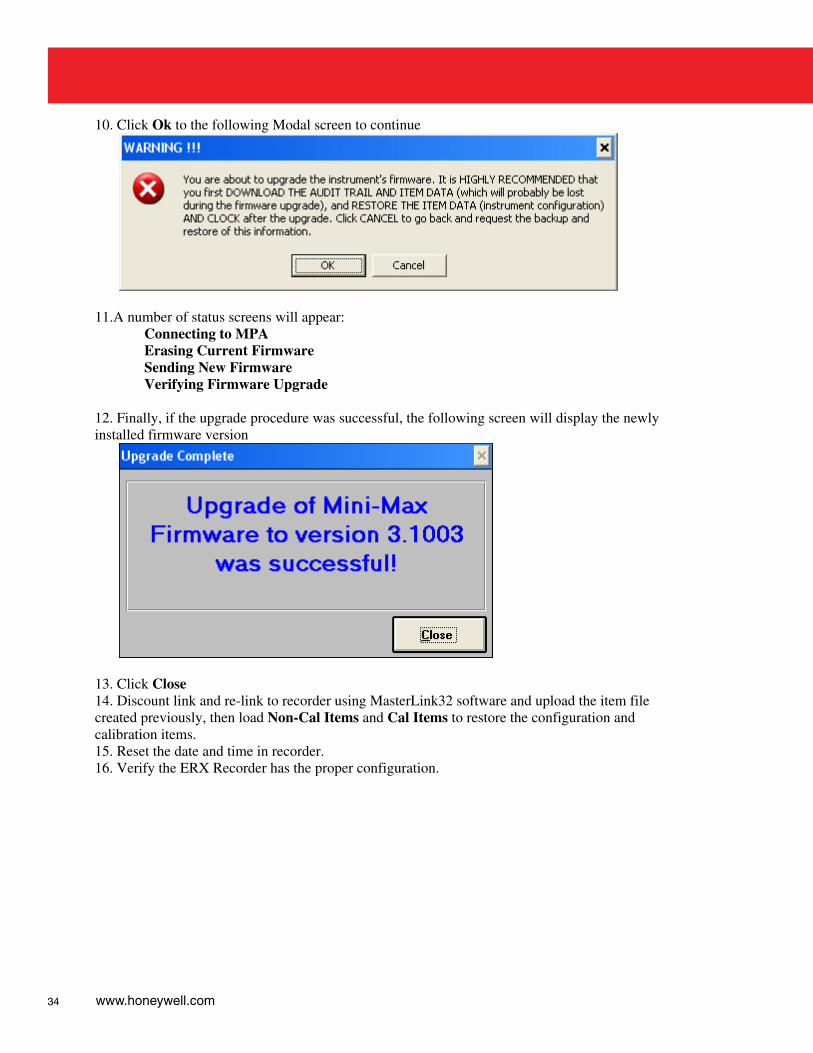
10. Click Ok to the following Modal screen to continue
11.A number of status screens will appear:
Connecting to MPA Erasing Current Firmware Sending New Firmware Verifying Firmware Upgrade
12. Finally, if the upgrade procedure was successful, the following screen will display the newly installed firmware version
13. Click Close 14. Discount link and re-link to recorder using MasterLink32 software and upload the item file created previously, then load Non-Cal Items and Cal Items to restore the configuration and calibration items. 15. Reset the date and time in recorder. 16. Verify the ERX Recorder has the proper configuration.
35
Putting the ERX Recorder into “Shutdown” Shutdown is a mode of operation invoked by the user prior to placing the instrument into storage or prior to performing some type of board maintenance. The MasterLink32 Link software manual describes the procedure for putting the ERX Recorder into shutdown. There are two types of “Shutdown” that can be induced into the ERX Recorder; Partial and Complete. The connection status of the battery packs determines which type of Shutdown the instrument assumes. Partial Shutdown To put the ERX Recorder into “partial shutdown”, from MasterLink32 Link software, select and confirm “SHUTDOWN” from the “Instrument” menu. Leave the main battery plugged-in. In partial shutdown, the recorder’s real-time clock will continue to update; however, the sampling of pressure or temperature of the gas no longer occurs. The LCD will show dashes “- - - - - - - - “across the display. The recorder still draws normal background current from the main battery when placed in partial shutdown, and it preserves all item values and audit trail information. To recover from a partial shutdown, i.e., return to Sample Mode, simply press the MI button. Complete Shutdown To put the ERX Recorder into “complete shutdown”, from MasterLink32 Link software, select and confirm “SHUTDOWN” from the “Instrument” menu, then unplug the main battery, and remove the super cap jumper. In complete shutdown, the clock of the recorder will stop working and the sampling of pressure or temperature of the gas no longer occurs. The configuration data of the recorder and all item values are retained in E2PROM. The LCD display will go blank once the batteries are unplugged. In order to bring the ERX Recorder out of a complete shutdown, simply plug in the main battery and replace the super cap jumper. It will be necessary to reset the date, time, and other items that are not current.
36 www.honeywell.com
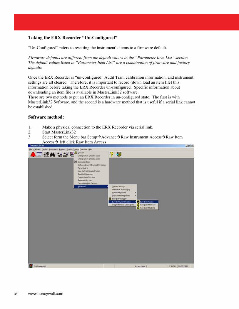
Taking the ERX Recorder “Un-Configured” “Un-Configured” refers to resetting the instrument’s items to a firmware default. Firmware defaults are different from the default values in the “Parameter Item List” section. The default values listed in “Parameter Item List” are a combination of firmware and factory defaults. Once the ERX Recorder is “un-configured” Audit Trail, calibration information, and instrument settings are all cleared. Therefore, it is important to record (down load an item file) this information before taking the ERX Recorder un-configured. Specific information about downloading an item file is available in MasterLink32 software. There are two methods to put an ERX Recorder in un-configured state. The first is with MasterLink32 Software, and the second is a hardware method that is useful if a serial link cannot be established. Software method: 1. Make a physical connection to the ERX Recorder via serial link. 2. Start MasterLink32 3 Select form the Menu bar SetupAdvanceRaw Instrument AccessRaw Item
Access left click Raw Item Access
37
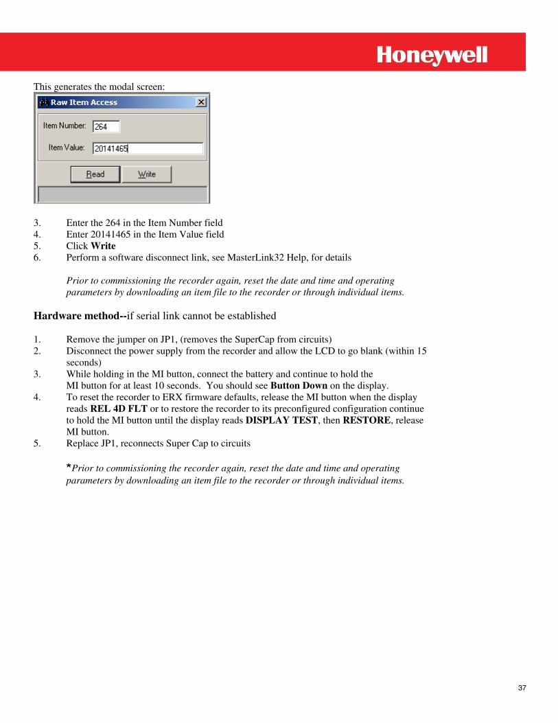
This generates the modal screen:
3. Enter the 264 in the Item Number field 4. Enter 20141465 in the Item Value field 5. Click Write 6. Perform a software disconnect link, see MasterLink32 Help, for details
Prior to commissioning the recorder again, reset the date and time and operating parameters by downloading an item file to the recorder or through individual items.
Hardware method--if serial link cannot be established 1. Remove the jumper on JP1, (removes the SuperCap from circuits) 2. Disconnect the power supply from the recorder and allow the LCD to go blank (within 15
seconds) 3. While holding in the MI button, connect the battery and continue to hold the MI button for at least 10 seconds. You should see Button Down on the display. 4. To reset the recorder to ERX firmware defaults, release the MI button when the display
reads REL 4D FLT or to restore the recorder to its preconfigured configuration continue to hold the MI button until the display reads DISPLAY TEST, then RESTORE, release MI button.
5. Replace JP1, reconnects Super Cap to circuits Prior to commissioning the recorder again, reset the date and time and operating
parameters by downloading an item file to the recorder or through individual items.
38 www.honeywell.com
Parameter Item List All items that make up the operating parameters, codes, alarms, calibration references, voltage levels and other information relative to operation or configuration of the Mercury Instruments ERX Recorder are listed below. When connected and linked to a computer, all ERX Recorder items can be displayed or changed in the Display/Item by Function of MasterLink32 software. Item Item Name & Description 061 Display Test
A test pattern generated by the microprocessor that gives a visual indication of the status of LCD; pattern energizes all segments of LCD.
104 A/D FAULT
This item indicates if an alarm for the A/D Converter was generated. If the microprocessor detects an A/D fault (Analog to Digital), an alarm is initiated and is indicated by placing dots on the LCD and “11111111” at Item 104. “00000000” at Item 104 indicates there is no A/D Converter Alarm. The alarm indicators will remain active until manually cleared (by software). Unlike other instrument alarms, an A/D Fault is usually a hardware failure that requires factory replacement of a component on the main circuit board, or a field replacement of the main board.
Default = 00000000 118 Reference Number 1 000000000 119 Reference Number 2 00000000 127 Instrument Type 10 P3 Pressure Coefficients 150 P3 Pressure Coefficient 27 0.000000 151 P3 Pressure Coefficient 28 0.000000 152 P3 Pressure Coefficient 29 0.000000 153 P3 Pressure Coefficient 30 30.00000 154 P3 Pressure Coefficient 31 0.000000 155 P3 Pressure Coefficient 32 0.000000 156 P3 Interval High Pressure Time 00 00 00 157 P3 Interval High Pressure Date 01-01-04 158 P3 Interval Low Pressure Time 00 00 00 159 P3 Interval Low Pressure Date 01-01-04 173 AT Reset Log Trigger 1 Board Coefficients 178 P1 Board Coefficients A 0.0000 179 P1 Board Coefficients B 1.0000 180 P1 Board Coefficients C 0.0000 181 P1 Board Coefficients D 1.0000 265 Reserved MA 00000000 266 Reserved MD 00000000 267 Reserved MC 00000000 Item Item Name & Description
39
P1 Pressure Coefficients 301 P1 Pressure Coefficient 1 0.000000 302 P1 Pressure Coefficient 2 30.00000 303 P1 Pressure Coefficient 3 0.000000 304 P1 Pressure Coefficient 4 0.000000 305 P1 Pressure Coefficient 5 0.000000 306 P1 Pressure Coefficient 6 30.00000 307 P1 Pressure Coefficient 7 0.000000 308 P1 Pressure Coefficient 8 0.000000 309 P1 Pressure Coefficient 9 0.000000 310 P1 Pressure Coefficient 10 30.00000 311 P1 Pressure Coefficient 11 0.000000 312 P1 Pressure Coefficient 12 0.000000 313 P1 Pressure Coefficient 13 0.000000 314 P1 Pressure Coefficient 14 30.00000 315 P1 Pressure Coefficient 15 0.000000 316 P1 Pressure Coefficient 16 0.000000 317 P1 Pressure Coefficient 17 0.000000 318 P1 Pressure Coefficient 18 30.00000 319 P1 Pressure Coefficient 19 0.000000 320 P1 Pressure Coefficient 20 0.000000 321 P1 Pressure Coefficient 21 0.000000 322 P1 Pressure Coefficient 22 30.00000 323 P1 Pressure Coefficient 23 0.000000 324 P1 Pressure Coefficient 24 0.000000 325 P1 Pressure Coefficient 25 0.000000 326 P1 Pressure Coefficient 26 30.00000 327 P1 Pressure Coefficient 27 0.000000 328 P1 Pressure Coefficient 28 0.000000 329 P1 Pressure Coefficient 29 0.000000 330 P1 Pressure Coefficient 30 30.00000 331 P1 Pressure Coefficient 31 0.000000 332 P1 Pressure Coefficient 32 0.000000 333 Call-In Trigger
Selection to determine what activity will cause an instrument call-in. Select:
0 - No Call-in Default: 1 - Alarm Call-in only
2 - Scheduled Call-in only 3 - Alarm & Scheduled Call-In 334 Scheduled Call-In Date
Date of next scheduled call-in. The host software must reset this after each call. Default = 01-01-00
40 www.honeywell.com
Item Item Name & Description 335 Scheduled Call-In Time
Time of next scheduled call-in. The host software may reset as needed or be reused for next call-in.
Default = 01:00:00 338 Scheduled Call-In Alarm
Status of scheduled call-in activity, ‘11111111’ indicates call-in activity since last interrogation and is intended to be reset to zero after each read. ‘00000000’ indicates no activity since last interrogation.
Default: 00000000 339 Scheduled Call-In Phone #
Phone number used for scheduled call-in. 340 Digi-Span Mode
Selection that determines what mode the ERX Recorder pulse output channels are set to. Default: 0 = No Digi-Span--Standard Pulse Out
1 = Gas Override--Pulse Channel A on 2 = Oil Override--Pulse Channel B on 3 = Automatic--Both Channels off P2 Pressure Coefficients 341 P2 Pressure Coefficient 1 0.000000 342 P2 Pressure Coefficient 2 30.00000 343 P2 Pressure Coefficient 3 0.000000 344 P2 Pressure Coefficient 4 0.000000 345 P2 Pressure Coefficient 5 0.000000 346 P2 Pressure Coefficient 6 30.00000 347 P2 Pressure Coefficient 7 0.000000 348 P2 Pressure Coefficient 8 0.000000 349 P2 Pressure Coefficient 9 0.000000 350 P2 Pressure Coefficient 10 30.00000 351 P2 Pressure Coefficient 11 0.000000 352 P2 Pressure Coefficient 12 0.000000 353 P2 Pressure Coefficient 13 0.000000 354 P2 Pressure Coefficient 14 30.00000 355 P2 Pressure Coefficient 15 0.000000 356 P2 Pressure Coefficient 16 0.000000 357 P2 Pressure Coefficient 17 0.000000 358 P2 Pressure Coefficient 18 30.00000 359 P2 Pressure Coefficient 19 0.000000 360 P2 Pressure Coefficient 20 0.000000 361 P2 Pressure Coefficient 21 0.000000 362 P2 Pressure Coefficient 22 30.00000 363 P2 Pressure Coefficient 23 0.000000 364 P2 Pressure Coefficient 24 0.000000 365 P2 Pressure Coefficient 25 0.000000 Item Item Name & Description
41
366 P2 Pressure Coefficient 26 30.00000 367 P2 Pressure Coefficient 27 0.000000 368 P2 Pressure Coefficient 28 0.000000 369 P2 Pressure Coefficient 29 0.000000 370 P2 Pressure Coefficient 30 30.00000 371 P2 Pressure Coefficient 31 0.000000 372 P2 Pressure Coefficient 32 0.000000 408 P3 Pressure Unit
Selection for the unit-of-measure for P2 pressure item 501, if changed to a different type, all P2 pressure-related items are converted and displayed to the new unit-of-measure.
See below for possible pressure unit choices.
Default: 0-PSIG 1-PSIA 2-kPA
3-mPa 4-Bar
5-mBar 6-KGcm2
7-in WC 8-in HG 9-mm HG
10-Oz 410 P3 Pressure Calibration Date
Date of the most recent P3 calibration Default: 01-01-04
411 P3 Pressure Transducer Serial Number
Default: 00000000 412 P3 Pressure Range
P3 transducer in PSI Default: 333.00
414 P3 Pressure Zero Offset
The most recent span value for P3 pressure transducer and obtained during a pressure span calibration. A value that is normally very close to 0.0000 and recalculated on each Pressure Span Calibration.
Default = 0.0000 415 P3 Pressure Previous Zero Offset
The previous P3 zero offset value recorded in item 414, updated on each calibration. Default: 0.0000
42 www.honeywell.com
Item Item Name & Description 417 P3 Pressure Span Factor
The most recent span value factor for P3 pressure transducer and obtained during a pressure span calibration. The value is normally very close to 1.0000 and recalculated on each pressure span calibration.
Default = 1.0000 418 P3 Pressure Previous Span Factor
The previous P3 span factor recorded in item 417, updated on each calibration. Default: 1.0000
419 P3 Pressure Range User
The upper pressure range limit, automatically scaled to the pressure units selected at item 408. If PSI is the selected pressure units, then item 419 will be the same as item 412. NOTE: The value at Item 419 and maybe manually edited to a rounded-off number, if desired.
Default = 333.00 420 P3 Gas Pressure
Gas pressure measured at the last wake-up. The pressure reading is scaled to the unit of measure selected at item 408.
421 P3 Average Pressure
P3 average pressure that occurred during the log interval 422 P3 Interval High Pressure
Highest P3 pressure reading recorded during the log interval. 423 P3 Interval Low Pressure
Lowest P3 pressure reading recorded during the log interval. 424 P3 Current Day Average Pressure
Average P3 pressure readings recorded for the current day. 425 P3 Previous Day Average Pressure
Previous value recorded in item 424 426 P3 Maximum Pressure
Maximum P3 pressure reading recorded since the recorder was last reset. Default: 0.000
427 P3 Maximum Pressure Time
Time of maximum P3 pressure reading was recorded since the recorder was last reset. Default: 00 00 00
428 P3 Maximum Pressure Date
Date of the maximum P3 pressure reading since the recorder was last reset. Default: 01-01-04
43
Item Item Name & Description 429 P3 Minimum Pressure
Minimum P3 pressure reading recorded since the recorder was last reset. Default: 333.00
430 P3 Minimum Pressure Time
Time of minimum P3 pressure reading was recorded since the recorder was last reset. Default: 00 00 00
431 P3 Minimum Pressure Date
Date of the minimum P3 pressure reading since the recorder was last reset. Default: 01-01-04
Board Coefficients 441 P2 Board Coefficients A 0.0000 442 P2 Board Coefficients B 1.0000 443 P2 Board Coefficients C 0.0000 444 P2 Board Coefficients D 1.0000 445 P3 Board Coefficients A 0.0000 446 P3 Board Coefficients B 1.0000 447 P3 Board Coefficients C 0.0000 448 P3 Board Coefficients D 1.0000 451 P3 High Alarm
Binary indication whether a P3 high alarm occurred. Default: 00000000, No alarm
11111111, Alarm 452 P3 Low Alarm
Binary indication whether a P3 low alarm occurred. Default: 00000000, No alarm
11111111, Alarm 453 P3 Current Day High Pressure
Maximum P3 pressure reading recorded during the current day. Default: 0.000
454 P3 Current Day Low Pressure
Minimum P3 pressure reading recorded during the current day. Default: 333.00
455 P3 Pressure High Alarm Limit
User defined P3 pressure limits that if exceeded will cause the recorder to alarm. 456 P3 Pressure Low Alarm Limit
P3 pressure limits that if exceeded will cause the recorder to alarm. Default: -1.00
44 www.honeywell.com
Item Item Name & Description 457 P3 Current Day High Time
Time of P3 maximum pressure reading was recorded during the current day. Default: 00 00 00
458 P3 Current Day High Date 459 P3 Pressure Dead Band
A hysteresis band that provides a buffer below the P3 pressure high limit and above the P3 low pressure limit when alarms are automatically cleared by RBX. The user-specified value determines the magnitude of the band. The P3 pressure measurement must pass completely through the dead band before the pressure alarm is automatically cleared.
Default: 5.00 481 Max Audit Trail Records
Maximum number of Audit Trail records Default: 5045
483 Alarm Message
Optional alphanumeric character (8) that is a user-defined text string is displayed on the LCD in 2-second intervals when an alarm has occurred. That is, typing the word ‘ALARM’ in item 483 will cause the display to alternate between a pressure reading and ALARM every 8 seconds.
Default: Blank 484 Alarm Channel Control
Selection to determine if the Alarm Channel at TB2 is used as an alarm pulse output or used to control power of an external device; that is cellular phones, modems, and etc.
Code Value Default: 0 Alarm Pulse Output
1 Modem Power Control 498 P3 Current Day Low Time
Time of lowest recorded P3 pressure reading during the current day. Default: 00 00 00
499 P3 Current Day Low Date
Default: 01-01-04 500 P1 Gas Pressure
The last recorded measurement of gas pressure from the primary pressure transducer and scaled to the selected pressure units at item 549.
Default: 0.00 501 P2 Gas Pressure
The last recorded measurement of gas pressure from the primary pressure transducer and scaled to the selected pressure units at item 550.
Default: 0.00 Item Item Name & Description 502 Temperature
45
The last recorded measurement of gas temperature and is scaled to the selected temperature units at 551.
Default: -40.00 503 Case Temperature
The last recorded measurement of the air temperature inside the recorder, considered an ambient temperature measurement.
Default: -40.00 504 Case Maximum Temperature
The highest recorded case temperature measurement since the recorder was last reset. Default: -40.00
505 Case Minimum Temperature
The lowest recorded case temperature measurement since the recorder was last reset. Default: 165.00
506 P1 Pressure Calibration Zero Offset
The most recent span value for P1 pressure transducer and obtained during a pressure span calibration. A value that is normally very close to 1.0000 and recalculated on each Pressure Span Calibration.
Default = 0.000 507 P1 Previous Calibration Zero Offset
The previous P1 span factor recorded in item 506 and is updated on each calibration. Default: 0.000
508 P1 Pressure Calibration Span Factor
The most recent span value factor for P1 pressure transducer and obtained during a pressure span calibration. The value is normally very close to 1.0000 and recalculated on each pressure span calibration.
Default = 1.0000 509 P1 Previous Calibration Span Factor
The previous P1 span factor recorded in item 508 and is updated on each calibration. Default: 1.0000
510 P2 Calibration Zero Offset
The most recent span value for P2 pressure transducer and obtained during a pressure span calibration. A value that is normally very close to 0.0000 and recalculated on each Pressure Span Calibration.
Default: 0.0000 511 P2 Previous Calibration Zero Offset
The previous P2 zero offset value recorded in item 510 and is updated on each calibration.
Default: 0.0000 Item Item Name & Description 512 P2 Pressure Calibration Span Factor
The most recent span value factor for P2 pressure transducer and obtained during a pressure span calibration. The value is normally very close to 1.0000 and recalculated on each pressure span calibration.
46 www.honeywell.com
Default = 1.0000 513 P2 Previous Calibration Span Factor
The previous P2 span factor recorded in item 512 and is updated on each calibration. Default: 0.000
514 Temperature Calibration Zero
The current temperature zero offset calibration constant. The value is normally very close to 0.00 and calculated on each temperature zero calibration.
Default: 0.00 515 Temperature Previous Calibration Zero Offset
The previous temperature zero offset constant recorded in item 514 and is updated on each calibration.
Default: 0.00 516 Temperature Calibration Span
The most recent temperature span value factor obtained during a temperature span calibration. The value is normally very close to 1.0000 and recalculated on each temperature span calibration.
Default: 1.0000 517 Temperature Previous Calibration Span Factor
The previous temperature span factor recorded in item 516, updated on each calibration. Default: 1.0000
518 P1 Pressure Calibration Date
The date automatically obtained form item 583 at the time of the P1 pressure zero calibration.
Default: 01-01-04 519 P2 Pressure Calibration Date
The date automatically obtained form item 583 at the time of the P1 pressure zero calibration.
Default: 01-01-04 520 Temperature Calibration Date
The date automatically obtained form item 583 at the time of the temperature zero calibration.
Default: 01-01-04 521 Battery Voltage Reading
Battery voltage reading obtained during the most recent wake-up.
47
Item Item Name & Description 522 Battery Low Volt Limit
Voltage limit at which the recorder will automatically generate a low voltage alarm if the battery reading, reads below limit.
Default: 4.30 523 Shutdown Voltage Limit
The voltage level at which “..H.E.L.P..” is displayed on the LCD as an indication that the battery is about dead and needs to be replaced.
Default: 4.00 528 Clear Alarms via LCD
This item enables the clearing of all active alarms via the MI Logo. During the Display List Mode, the "E.E.E.E.E.E.E.E." display will appear after scrolling through all active alarms. Allow the recorder to time-out (1-minute) at this display to clear the alarms. If the MI Logo is used to scroll to the next display item in the list the alarms are not cleared.
Code 0- No Default: 1- Yes
530 Display List 1 Item 1 580, Site ID Number 531 Display List 1 Item 2 582, Time 532 Display List 1 Item 3 583, Date 533 Display List 1 Item 4 503, Case Temperature 534 Display List 1 Item 5 521, Battery Voltage Reading 535 Display List 1 Item 6 255, Reserved 536 Live Display Enable
If configured, the recorder will display live P1, P2, and P3 live pressure and temperature readings as part of the Display List. If enabled, the first live parameter will follow the last Display List 1 item and prior to the first Display List 2 item. All live parameters have a 30-minute time-out, instead of the usual 1-minute time-out.
Default: Same as item 576 537 Display List 2 Item 1 631, P1 Maximum 538 Display List 2 Item 2 637 Maximum Pressure Time 539 Display List 2 Item 3 638, Maximum Pressure Date 540 Display List 2 Item 4 632, P1 Minimum 541 Display List 2 Item 5 639, Minimum Pressure Time 542 Display List 2 Item 6 640, Minimum Pressure Date 543 Display List 2 Item 7 651, P1 Interval Low Pressure 544 Display List 2 Item 8 650, P1 Interval High 545 Display List 2 Item 9 649, P1 Interval Average 546 Display List 2 Item 10 255, Reserved 547 Display List 2 Item 11 255, Reserved 548 Display List 2 Item 12 255, Reserved
48 www.honeywell.com
Item Item Name & Description 549 Pressure 1 Units
Selection for the unit-of-measure for P1 pressure item 500 and if changed to a different type, all P1 pressure related items are converted and displayed in the new unit-of-measure. See below for possible pressure unit choices.
550 Pressure 2 Units
Selection for the unit-of-measure for P2 pressure item 501 and if changed to a different type, all P2 pressure related items are converted and displayed to the new unit-of-measure.
Possible choices for Item 549, 550, and 408 are:.
Code Value Default: 0 PSIG
1 PSIA 2 kPA
3 mPa 4 Bar 5 mBar 6 KGcm2 7 in WC 8 in HG 9 mm HG 10 Oz 11 Volts 12 Millivolts 551 Temperature Units
Selection for the unit-of-measure for gas temperature item 502 and if changed to a different type, all temperature related items are converted and displayed to the new unit-of-measure. See below for possible temperature unit choices.
Code Value Default: 0 Fahrenheit
1 Celsius 2 Rankine 3 Kelvin 552 Pressure Display Resolution
This item controls the how many decimal place that recorder will displayed and applies to all pressure units.
Code Value 0 XXXXXXXX. 1 XXXXXXX.X
Default: 2 XXXXXX.XX 3 XXXXX.XXX
49
Item Item Name & Description 553 P1 Pressure High Alarm Limit
The pressure reading that automatically produces a high-pressure alarm. This value is a user selectable item and is normally set somewhere between 50 & 100% of transducer range.
Default: 111.00 554 P1 Pressure Low Alarm Limit
The pressure reading that automatically produces a low-pressure alarm. . Default: -1.00
555 P2 Pressure High Alarm Limit
The pressure reading that automatically produces a high-pressure alarm. This value is a user selectable item and is normally set somewhere between 50 & 100% of transducer range.
Default: 222.00 556 P2 Pressure Low Alarm Limit
The pressure reading that automatically produces a low-pressure alarm. . Default: -1.00
557 Temperature High Alarm Limit
The temperature reading that automatically produces a high-temperature alarm. This value is a user selectable item.
Default: 165.00 558 Temperature Low Alarm Limit
The temperature reading that automatically produces a low-temperature alarm. . Default: -35.00
Alarm Status Indicators for items 559 through 568: Code Value
Default: 00000000 No alarm 11111111 Alarm A 50-millisecond alarm pulse, transmitted out the alarm channel occurs at the time the recorder alarms. All alarms must be cleared before the recorder will again output a 50-millisecond alarm pulse. 559 P1 High Pressure Alarm Code Value
Default: 00000000 No alarm 11111111 Alarm 560 P1 Low Pressure Alarm Code Value
Default: 00000000 No alarm 11111111 Alarm
50 www.honeywell.com
Item Item Name & Description 561 P2 High Pressure Alarm Code Value
Default: 00000000 No alarm 11111111 Alarm 562 P2 Low Pressure Alarm Code Value
Default: 00000000 No alarm 11111111 Alarm 563 Temperature High Alarm
A gas temperature reading that will automatically produce a high temperature alarm. This value is user selectable and is normally set to a value that is greater than the average flowing temperature. Setting the limit to 170.00 can defeat a high temperature alarm.
Default: 170.00. 558 Temperature Low Alarm Limit
A gas temperature reading that will automatically produce a low temperature alarm. This value is user selectable and is normally set to a value that is greater than the average flowing temperature. Setting the limit to -40.00 can defeat a low temperature alarm.
Default: -40.00. 568 Alarm Output Code Value
Default: 00000000 No alarm 11111111 Alarm 569 Transducer Type
This item is for reference only and does not effect the pressure transducer calibration or performance.
Code Value Default: 0 Gauge
1 Absolute 570 P1 Pressure Range PSI
The upper limit of the installed P1 pressure transducer and is always expressed in PSI. Default: 111.00
571 P2 Pressure Range PSI
The upper limit of the installed P2 pressure transducer and is always expressed in PSI. Default: 222.00
572 P1 Pressure Range User
The upper pressure range limit, automatically scaled to the pressure units selected at item 549. If PSI is the selected pressure units, then item 572 will be the same as item 571. NOTE: The value at item 572 may be manually edited to a rounded-off number, if desired.
Default: 111.00
51
Item Item Name & Description 573 P2 Pressure Range User
The upper pressure range limit, automatically scaled to the pressure units selected at item 550. If PSI is the selected pressure units, then item 573 will be the same as item 572. NOTE: The value at item 573 may be manually edited to a rounded-off number, if desired.
Default: 111.00 574 P1 Transducer Serial Number
Note: Forcing factory defaults will not change the value of this item. Default: 00000000
575 P2 Transducer Serial Number
Note: Forcing factory defaults will not change the value of this item. Default: 00000000
576 Instrument Configuration
Selection that defines the number and type of transducers (pressure or temperature) installed in a particular recorder. MasterLink32 uses this item to determine number and type of transducers installed in the recorder. If improperly configured will limit the functionality of MasterLink32.
Code Value Default: 1 P1
2 3 P1 & P2 4 T 5 P1 & T 7 P1, P2, & T 8 P1, P2, P3, 9 P1, P2, P3, & T 577 Recorder Serial Number
The numerical portion of the instrument's serial number label that is located in the inside of door. Disregard the leading zero, the first two digits indicate the year of manufacture, and the last five digits are assigned sequentially from the beginning of the year. Default: 0
578 Firmware Version
This item contains the recorder’s operating firmware version number. Automatically insert when a firmware file it upload in the recorder.
579 Instrument Type
Use by MasterLink32 and other software programs that identifies the instrument type. 580 Site ID Number
First of two numeric fields that are used by MasterLink32 and other software programs to identify the recorder and up to eight digits may be used and the only valid characters are 0-9.
Default: Instrument serial number
52 www.honeywell.com
Item Item Name & Description 581 Site ID Number Part 2
Second of two numeric fields that are used by MasterLink32 and other software programs to identify the recorder and up to eight digits may be used and the only valid characters are 0-9.
Default: Instrument serial number 582 Time
Settable Real Time Clock that displays hours, minutes and seconds in 24-hour "military format," e.g., 14:30:02 would indicate 2 seconds past 2:30 PM. This Time (and Date, item 583) is used to time-stamp records stored in data logger memory.
Default: 12 00 00
583 Date A numeric field that indicates the day, month and year of a calendar year and which automatically tracks the days in the month, including a leap year. Leading zeros are required, where applicable. Date and time are used to time-stamp records stored in data logger.
Default: 01-01-04 584 Date Format
A user configurable item that allows the user to determine how a date is entered and displayed.
Code Value Default: 0 MM - DD - YY
1 DD - MM - YY 585 Log Interval
User selected period that determines how often a time-stamped record is placed in the Audit Trail and is identified by “TIME”. All available log intervals will produce a time-stamped record at the top-of-hour. Log Intervals less than 60 minutes will also time-stamp records at each selected interval, starting at the top of the hour.
Code Value 0 24 Hours
Default: 1 60 Minutes 2 30 Minutes 3 15 Minutes 4 5 Minutes 5 1 Minute 586 Sample Interval
User selected time period that determines how often the recorder will wake up to measure (sample) the analog inputs, i.e., P1, P2, P3 T, Case Temp, and Battery Voltage.
Code Value 0 60 Seconds 1 30 Seconds 2 15 Seconds
Default 3 10 Seconds
53
Item Item Name & Description 587 Start Time
A user selected time of day when selected items are re-zeroed and the next day’s calculations begin. Generally the "Start Time" is set to midnight to coincide with the calendar day, but other top of the hour times may be entered.
Default: 00 00 00
588 Instrument Baud Rate Codes (0-8) are to select the instrument’s baud rate for all local serial connection. If Auto baud is selected the instrument will connect to the computer at the baud rate at which the software is set. If any other selection is made the computer baud rate must match that of the instrument in order to communicate.
Code Value Code Value 0 9600 5 Not Used 1 4800 6 19200 2 2400 7 38400 3 1200 8 Auto Baud - Default 4 Not Used Audit Report Items-Default
The ten user-selectable recorder items that can be stored in memory and then used to create historical data based on the selected Audit Trail items. Any of the instrument's items can be selected, but generally should be restricted to items whose value can be graphed, such as pressure or temperature, etc. Any report position can be left blank (unused) by inserting the number "255" instead of an item code number.
Pressure only default Audit Trail 589 Report Item 2 500, P1 Pressure 590 Report Item 2 651, P1 Interval Low Pressure 591 Report Item 3 650, P1 Interval High Pressure 592 Report Item 4 649, P1 Interval Avg. Pressure 593 Report Item 5 672, P1 Current Day Low Press. 594 Report Item 6 681, P1 Current Day Low Time 595 Report Item 7 671, P1 Current Day High Press 596 Report Item 8 679, P1 Current Day Hi time 597 Report Item 9 503, Case Temperature 598 Report Item 10 521, Battery Voltage Reading 599 Time Trigger Enable
When enabled, item 585 log interval will cause an Audit Trail record to be placed in memory and is indicated by the log trigger: Time.
Code Value 0 Inactive
Default: 1 Active
54 www.honeywell.com
Item Item Name & Description 600 Calibration Trigger Enable
When enabled, a calibration of the recorder will cause an Audit Trail record to be placed in memory and is indicated by the log trigger: Calibration
Code Value 0 Inactive
Default: 1 Active 601 Alarm Trigger Enable
When enabled, the occurrence of any alarm will cause an Audit Trail record to be placed in memory and is indicated by the log trigger: Alarm
Code Value 0 Inactive
Default: 1 Active 602 Serial Trigger Enable
When enabled, any successful sign-on through the serial port will cause an Audit Trail record to be placed in memory and is indicated by the log trigger: Serial
Code Value 0 Inactive
Default: 1 Active 603 Mag Trigger Enable-MI Logo Button
When enabled, anytime the MI Logo button is used to initiate the display list mode, an Audit Trail record is placed in memory and is indicated by the log trigger: Mag
Code Value 0 Inactive
Default: 1 Active 604 Change Trigger Enable
When enabled, anytime a user changes an item value, an Audit Trail record is placed in memory and is indicated by the log trigger: Change
Code Value 0 Inactive
Default: 1 Active P3 Pressure Coefficients 1-26 605 P3 Pressure Coefficient 1 0.000000 606 P3 Pressure Coefficient 2 30.00000 607 P3 Pressure Coefficient 3 0.000000 608 P3 Pressure Coefficient 4 0.000000 609 P3 Pressure Coefficient 5 0.000000 610 P3 Pressure Coefficient 6 30.00000 611 P3 Pressure Coefficient 7 0.000000 612 P3 Pressure Coefficient 8 0.000000 613 P3 Pressure Coefficient 9 0.000000 614 P3 Pressure Coefficient 10 30.00000 615 P3 Pressure Coefficient 11 0.000000
55
Item Item Name & Description 616 P3 Pressure Coefficient 12 0.000000 617 P3 Pressure Coefficient 13 0.000000 618 P3 Pressure Coefficient 14 30.00000 619 P3 Pressure Coefficient 15 0.000000 620 P3 Pressure Coefficient 16 0.000000 621 P3 Pressure Coefficient 17 0.000000 622 P3 Pressure Coefficient 18 30.00000 623 P3 Pressure Coefficient 19 0.000000 624 P3 Pressure Coefficient 20 0.000000 625 P3 Pressure Coefficient 21 0.000000 626 P3 Pressure Coefficient 22 30.00000 627 P3 Pressure Coefficient 23 0.000000 628 P3 Pressure Coefficient 24 0.000000 629 P3 Pressure Coefficient 25 0.000000 630 P3 Pressure Coefficient 26 30.00000 631 P1 Maximum Pressure
The maximum P1 pressure sample reading since the last reset. Default: -1.00
632 P1 Minimum Pressure
The minimum P1 pressure sample reading since the last reset. Default: 9999.00
633 P2 Maximum Pressure
The maximum P2 pressure sample reading since the last reset. Default: -1.00
634 P2 Minimum Pressure
The minimum P2 pressure sampled reading since the last reset. Default: 9999.00
635 Gas Temperature Maximum
The maximum temperature sample reading since the last reset. Default: -40.00
The minimum temperature sample reading since the last reset. Default: 165.00
637 P1 Maximum Pressure Time
The time the recorder’s maximum P1 pressure sample reading occurred, since the recorder was, last reset.
Default: 00 00 00 638 P1 Maximum Pressure Date
The date the recorder’s maximum P1 pressure sample reading occurred, since the recorder was last reset.
Default: 01-01-04
56 www.honeywell.com
Item Item Name & Description 639 P1 Minimum Pressure Time
The time the recorder’s minimum P1 pressure sample reading occurred, since the recorder was, last reset.
Default: 00 00 00 640 P1 Minimum Pressure Date
The date the recorder’s minimum P1 pressure sample reading occurred, since the recorder was last reset.
Default: 01-01-04 641 P2 Maximum Time
The time the recorder’s maximum P2 pressure sample reading occurred, since the recorder was last reset.
Default: 00 00 00 642 P2 Maximum Date
The date the recorder’s maximum P2 pressure sample reading occurred, since the recorder was last reset.
Default: 01-01-04 643 P2 Minimum Time
The time the recorder’s minimum P2 pressure sample reading occurred, since the recorder was last reset.
Default: 00 00 00 644 P2 Minimum Date
The date the recorder’s minimum P2 pressure sample reading occurred, since the recorder was last reset.
Default: 01-01-04 645 Temperature Maximum Time
The time the recorder’s maximum T1 temperature sample reading occurred, since the recorder was last reset.
Default: 00 00 00 646 Temperature Maximum Date
The date the recorder’s maximum T1temperature sample reading occurred, since the recorder was last reset.
Default: 01-01-04 647 Temperature Minimum Time
The time the recorder’s minimum T1 temperature sample reading occurred, since the recorder was last reset.
Default: 00 00 00
57
Item Item Name & Description 648 Temperature Minimum Date
The time the recorder’s minimum T1 temperature sample reading occurred, since the recorder was last reset.
Default: 01-01-04
P1 highest pressure reading that occurred during the interval. Default: -1.00
651 P1 Interval Low
P1 lowest pressure reading that occurred during the interval. Default: 9999.99
652 P2 Interval Average
P2 pressure reading averages of the entire recorder’s sampled readings during the interval.
Default: -1.00 653 P2 Interval High
P2 highest pressure reading that occurred during the interval. Default: -1.00
654 P2 Interval Low
P2 lowest pressure reading that occurred during the interval. Default: 9999.99
655 Temperature Interval Average
T1 temperature reading averages of the entire recorder’s sampled readings during the interval.
Default: -40.00 656 Temperature Interval High
T1 temperature highest sample reading that occurred during the interval. Default: -40.00
657 Temperature Interval Low
T1 temperature lowest sample reading that occurred during the interval. Default: 165.00
658 P1 Interval High Time
The time at which the recorder’s maximum P1 pressure reading (item 650) occurred during the interval.
Default: 00 00 00
The date at which the recorder’s maximum P1 pressure reading (item 650) occurred, during the interval.
Default: 01-01-04
58 www.honeywell.com
Item Item Name & Description 660 P1 Interval Low Time
The time at which the recorder’s minimum P1 pressure reading (item 651) occurred during the interval.
Default: 00 00 00 661 P1 Interval Low Date 662 The date at which the recorder’s minimum P1 pressure reading (item 651) occurred
during the interval. Default: 00 00 00
663 The time at which the recorder’s maximum P2 pressure reading (item 653) occurred
during the interval Default: 00 00 00
664 The date at which the recorder’s maximum P2 pressure reading (item 653) occurred
during the interval. Default: 01-01-04
665 The time at which the recorder’s minimum P2 pressure reading (item 654) occurred
during the interval. Default: 00 00 00
665 P2 Interval Low Date
The date at which the recorder’s minimum P2 pressure reading (item 654) occurred during the interval.
Default: 01-01-04 666 The time at which the recorder’s maximum T1 temperature sample reading (item 656)
occurred during the interval. Default: 00 00 00
667 Temperature Interval High Date
The date at which the recorder’s maximum T1 temperature sample reading (item 656) occurred during the interval.
Default: 01-01-04 668 Temperature Interval Low Time
The time at which the recorder’s minimum T1 temperature sample reading (item 656) occurred during the interval.
Default: 00 00 00 669 Temperature Interval Low Date
The date at which the recorder’s minimum T1 temperature sample reading (item 656) that occurred during the interval.
Default: 01-01-04 670 P1 Current Day Average
Recorder’s average P1 sampled pressure readings that occurred during the current day. Default: -1.00
59
Item Item Name & Description 671 The maximum P1 pressure sampled readings that occurred during the current day.
Default: -1.00 672 P1 Current Day Low
The minimum P1 pressure sampled readings that occurred during the current day. Default: 9999.99
673 P2 Current Day Average
Recorder’s average P2 sampled pressure readings that occurred during the current day. Default: -1.00
674 P2 Current Day High
The maximum P2 pressure sampled reading that occurred during the current day. Default: -1.00
675 P2 Current Day Low
The minimum P2 pressure sampled reading that occurred during the current day. Default: 9999.99
676 Temperature Current Day Average
Recorder’s average T1 temperature sampled readings that occurred during the current day.
Default: -40.00 677 Temperature Current Day High
The maximum T1 temperature sampled reading that occurred during the current day. Default: -40.00
678 Temperature Current Day Low
The minimum T1 temperature sampled reading that occurred during the current day. Default: 165.00
679 P1 Current Day High Time
The date at which the recorder’s maximum P1 pressure reading (item 671) occurred during the current day.
Default: 01-01-04 680 P1 Current Day High Date
The date at which the recorder’s maximum P1 pressure reading (item 671) occurred during the current day.
Default: 01-01-04 681 P1 Current Day Low Time
The time at which the recorder’s minimum P1 pressure reading (item 671) occurred during the current day.
Default: -1.00
60 www.honeywell.com
Item Item Name & Description 682 P1 Current Day Low Date
The date at which the recorder’s minimum P1 pressure reading (item 672) occurred during the current day.
Default: 9999.99 683 P2 Current Day High Time
The time at which the recorder’s maximum P2 pressure reading (item 674) occurred during the current day.
Default: 00 00 00 684 P2 Current Day High Date
The date at which the recorder’s maximum P2 pressure reading (item 674) occurred during the interval.
Default: 01-01-04 685 P2 Current Day Low Time
The time at which the recorder’s minimum P2 pressure reading (item 675) occurred during the current day.
Default: 00 00 00 686 P2 Current Day Low Date
The date at which the recorder’s minimum P2 pressure reading (item 675) occurred during the current day.
Default: 01-01-04 687 Temperature Current Day High Time
The time at which the recorder’s minimum T1 temperature reading (item 677) occurred during the current day. Default: 00 00 00
688 Temperature Current Day High Date
The date at which the recorder’s maximum T1 temperature reading (item 677) occurred during the current day.
Default: 01-01-04 689 Temperature Current Day Low Time
The time at which the recorder’s minimum T1 temperature reading (item 678) occurred during the current day.
Default: 00 00 00 690 Temperature Current Day Low Date
The date at which the recorder’s minimum T1 temperature reading (item 678) occurred during the current day.
Default: 01-01-04 691 P1 Previous Day Average Pressure
Recorder’s average P1 sampled pressure readings that occurred during the previous day. Default: -1.00
61
Item Item Name & Description 692 P1 Previous Day High Pressure
Recorder’s maximum P1 sampled pressure readings that occurred during the previous day.
Default: -1.00 693 P1 Previous Day Low Pressure
Recorder’s minimum P1 sampled pressure readings that occurred during the previous day.
Default: 99999.99 694 Recorder’s average P2 sampled pressure readings that occurred during the previous day.
Default: -1.00 695 P2 Previous Day High Pressure
Recorder’s maximum P2 sampled pressure readings that occurred during the previous day.
Default: -1.00 696 P2 Previous Day Low Pressure
Recorder’s minimumP2 sampled pressure readings that occurred during the previous day. Default: 99999.99
697 Temperature Previous Day Average
Recorder’s average T1 sampled temperature readings that occurred during the previous day.
Default: -1.00 698 Temperature Previous Day High
Recorder’s maximum T1 sampled temperature readings that occurred during the previous day.
Default: -1.00 699 Temperature Previous Day Low
Recorder’s minimum T1 sampled temperature readings that occurred during the previous day.
Default: -1.00 700 P1 Previous Day High Time
The time at which the recorder’s maximum P1 sampled pressure reading (item 692) occurred during the previous day.
Default: 00 00 00 701 P1 Previous Day High Date
The date at which the recorder’s maximum P1 sampled pressure reading (item 692) occurred during the previous day.
Default: 01-01-04
62 www.honeywell.com
Item Item Name & Description 702 P1 Previous Day Low Time
The time at which the recorder’s minimum P1 sampled pressure reading (item 693) occurred during the previous day.
Default: 00 00 00 703 P1 Previous Day Low Date
The date at which the recorder’s minimum P1 sampled pressure reading (item 693) occurred during the previous day.
Default: 01-01-04 704 P2 Previous Day High Time
The time at which the recorder’s maximum P2 sampled pressure reading (item 695) occurred during the previous day.
Default: 00 00 00 705 The date at which the recorder’s maximum P2 sampled pressure reading (item 695)
occurred during the previous day. Default: 01-01-04
706 P2 Previous Day Low Time
The time at which the recorder’s minimum P2 sampled pressure reading (item 696) occurred during the previous day.
Default: 00 00 00 707 P2 Previous Day Low Date
The date at which the recorder’s minimum P2 sampled pressure reading (item 696) occurred during the previous day.
Default: 01-01-04 708 Temperature Previous Day High Time
The time at which the recorder’s maximum T1 sampled temperature reading (item 698) occurred during the previous day.
Default: 00 00 00 709 Temperature Previous Day High Date
The date at which the recorder’s maximum T1 sampled temperature reading (item 698) occurred during the previous day.
Default: 01-01-04 710 Temperature Previous Day Low Time
The time at which the recorder’s minimumT1 sampled temperature reading (item 699) occurred during the previous day.
Default: 00 00 00 711 Temperature Previous Day Low Date
The date at which the recorder’s minimum T1 sampled temperature reading (item 699) occurred during the previous day.
Default: 00 00 00
63
Item Item Name & Description 769 RBX Alarm Enable
When the RBX function (Report By Exception) is disabled, all instrument alarms operate as in previous versions of firmware, i.e., alarms stay active until manually cleared. When RBX is enabled, instrument alarms are automatically cleared after the alarm parameter returns to its normal operating range, buffered by a user- specified dead band.
Code Value
Default: 0 Alarm 1 RBX Enable 770 P1 Dead Band
A hysteresis band that provides a buffer below the P1 pressure high limit and above the P1 low-pressure limit and if enabled, alarms are automatically cleared by RBX. The user-specified value determines the magnitude of the band. The P1 pressure measurement must pass completely through the dead band before the pressure alarm is automatically cleared.
Default: 5.00 771 Temperature Dead Band 10.0000
A hysteresis band that provides a buffer below the T1 temperature high limit and above the T1 temperature low limit and if enabled, alarms are automatically cleared by RBX. The user-specified value determines the magnitude of the band. The P1 pressure measurement must pass completely through the dead band before the pressure alarm is automatically cleared.
Default: 10.00 772 Battery Dead Band
A hysteresis band that provides a buffer below Default: 1.00
776 When enabled, a CLR ALARM log trigger is written in the Audit Trail at the time the
alarm is cleared, either manually or by RBX. Code Value
Default: 0 Inactive 1 Active 774 Protocol Code A
Enables or disables the sending of time-out error (error 21) during a serial link sign-on. Code Value
Default: 0 Send all errors 1 Time-out error 21 not sent 775 Timeout Delay 1
Time in seconds that ERX waits for the host computer to send an ENQ, following an EOT before issuing an error 21.
Default: 25
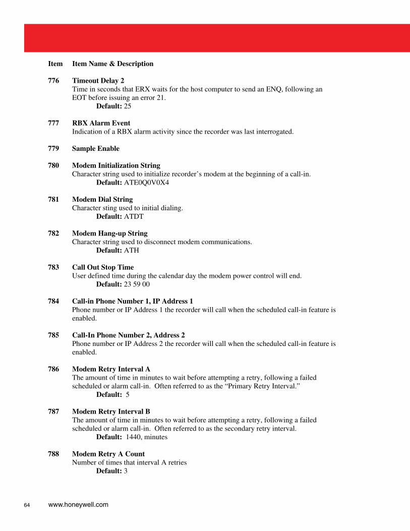
64 www.honeywell.com
Item Item Name & Description 776 Timeout Delay 2
Time in seconds that ERX waits for the host computer to send an ENQ, following an EOT before issuing an error 21.
Default: 25 777 RBX Alarm Event
Indication of a RBX alarm activity since the recorder was last interrogated. 779 Sample Enable 780 Modem Initialization String
Character string used to initialize recorder’s modem at the beginning of a call-in. Default: ATE0Q0V0X4
781 Modem Dial String
Character sting used to initial dialing. Default: ATDT
782 Modem Hang-up String
Character string used to disconnect modem communications. Default: ATH
783 Call Out Stop Time
User defined time during the calendar day the modem power control will end. Default: 23 59 00
784 Call-in Phone Number 1, IP Address 1
Phone number or IP Address 1 the recorder will call when the scheduled call-in feature is enabled.
785 Call-In Phone Number 2, Address 2
Phone number or IP Address 2 the recorder will call when the scheduled call-in feature is enabled.
786 Modem Retry Interval A
The amount of time in minutes to wait before attempting a retry, following a failed scheduled or alarm call-in. Often referred to as the “Primary Retry Interval.”
Default: 5 787 Modem Retry Interval B
The amount of time in minutes to wait before attempting a retry, following a failed scheduled or alarm call-in. Often referred to as the secondary retry interval.
Default: 1440, minutes 788 Modem Retry A Count
Number of times that interval A retries Default: 3
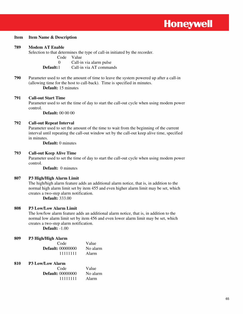
65
Item Item Name & Description 789 Modem AT Enable
Selection to that determines the type of call-in initiated by the recorder. Code Value
0 Call-in via alarm pulse Default:1 Call-in via AT commands
790 Parameter used to set the amount of time to leave the system powered up after a call-in
(allowing time for the host to call-back). Time is specified in minutes. Default: 15 minutes
791 Call-out Start Time
Parameter used to set the time of day to start the call-out cycle when using modem power control.
Default: 00 00 00 792 Call-out Repeat Interval
Parameter used to set the amount of the time to wait from the beginning of the current interval until repeating the call-out window set by the call-out keep alive time, specified in minutes.
Default: 0 minutes 793 Call-out Keep Alive Time
Parameter used to set the time of day to start the call-out cycle when using modem power control.
Default: 0 minutes 807 P3 High/High Alarm Limit
The high/high alarm feature adds an additional alarm notice, that is, in addition to the normal high alarm limit set by item 455 and even higher alarm limit may be set, which creates a two-step alarm notification.
Default: 333.00 808 P3 Low/Low Alarm Limit
The low/low alarm feature adds an additional alarm notice, that is, in addition to the normal low alarm limit set by item 456 and even lower alarm limit may be set, which creates a two-step alarm notification.
Default: -1.00 809 P3 High/High Alarm Code Value
Default: 00000000 No alarm 11111111 Alarm 810 P3 Low/Low Alarm Code Value
Default: 00000000 No alarm 11111111 Alarm
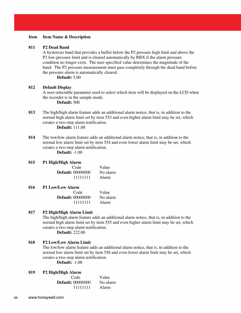
66 www.honeywell.com
Item Item Name & Description 811 P2 Dead Band
A hysteresis band that provides a buffer below the P2 pressure high limit and above the P2 low-pressure limit and is cleared automatically by RBX if the alarm pressure condition no longer exist. The user-specified value determines the magnitude of the band. The P2 pressure measurement must pass completely through the dead band before the pressure alarm is automatically cleared.
Default: 5.00 812 Default Display
A user-selectable parameter used to select which item will be displayed on the LCD when the recorder is in the sample mode.
Default: 500 813 The high/high alarm feature adds an additional alarm notice, that is, in addition to the
normal high alarm limit set by item 553 and even higher alarm limit may be set, which creates a two-step alarm notification.
Default: 111.00 814 The low/low alarm feature adds an additional alarm notice, that is, in addition to the
normal low alarm limit set by item 554 and even lower alarm limit may be set, which creates a two-step alarm notification.
Default: -1.00 815 P1 High/High Alarm Code Value
Default: 00000000 No alarm 11111111 Alarm 816 P1 Low/Low Alarm
Code Value Default: 00000000 No alarm
11111111 Alarm 817 P2 High/High Alarm Limit
The high/high alarm feature adds an additional alarm notice, that is, in addition to the normal high alarm limit set by item 555 and even higher alarm limit may be set, which creates a two-step alarm notification.
Default: 222.00 818 P2 Low/Low Alarm Limit
The low/low alarm feature adds an additional alarm notice, that is, in addition to the normal low alarm limit set by item 556 and even lower alarm limit may be set, which creates a two-step alarm notification.
Default: -1.00 819 P2 High/High Alarm Code Value
Default: 00000000 No alarm 11111111 Alarm
67
Item Item Name & Description 820 P2 Low/Low Alarm Code Value
Default: 00000000 No alarm 11111111 Alarm 821 Modem Wake-up Delay
Default: 50, Tenths of second

68 www.honeywell.com
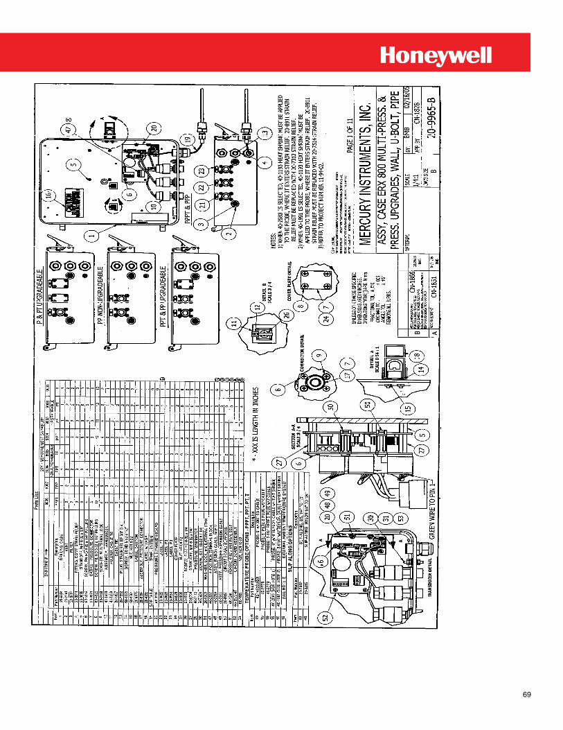
69
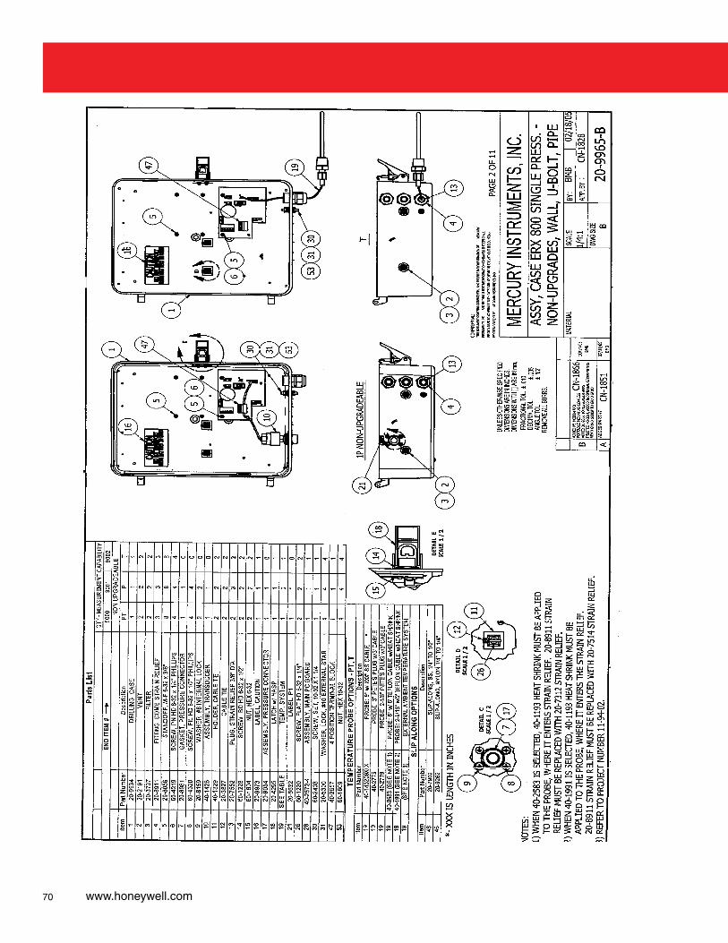
70 www.honeywell.com
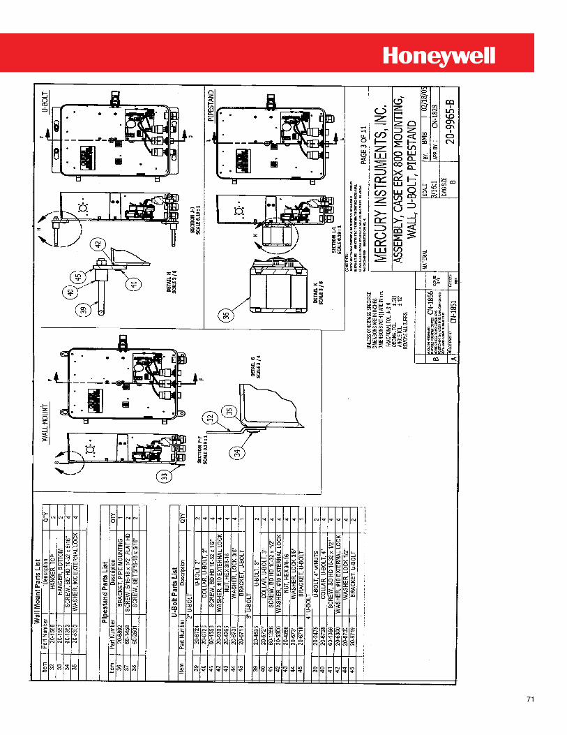
71
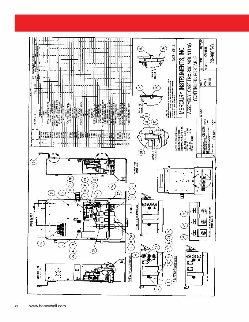
72 www.honeywell.com
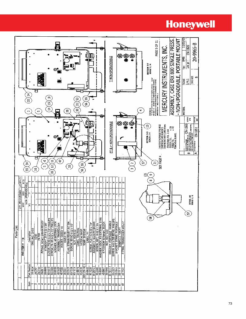
73
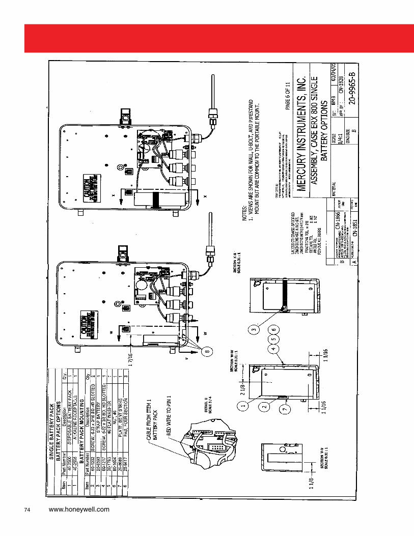
74 www.honeywell.com
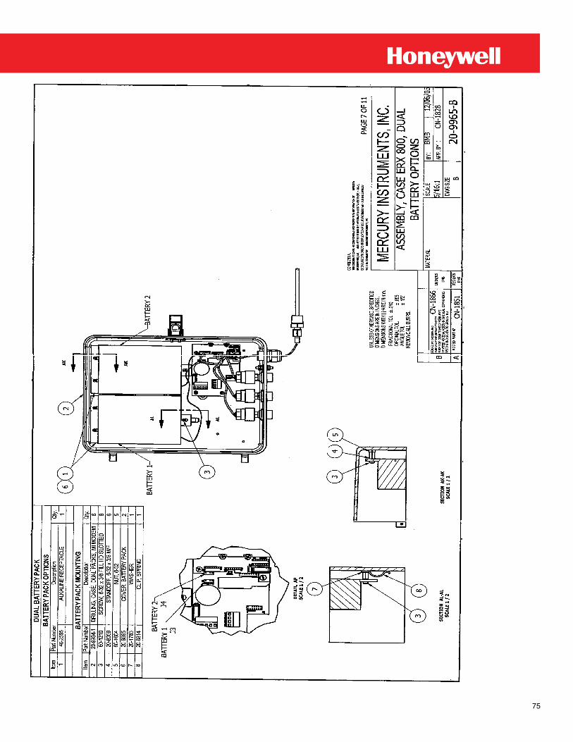
75
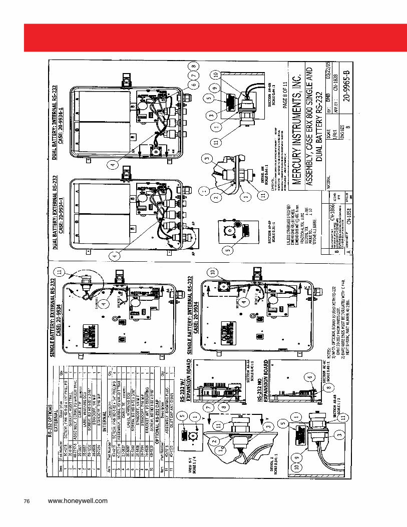
76 www.honeywell.com
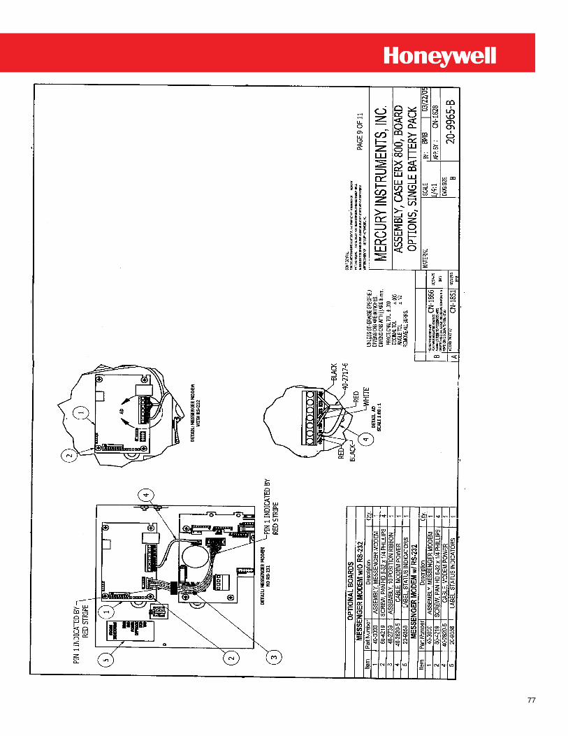
77
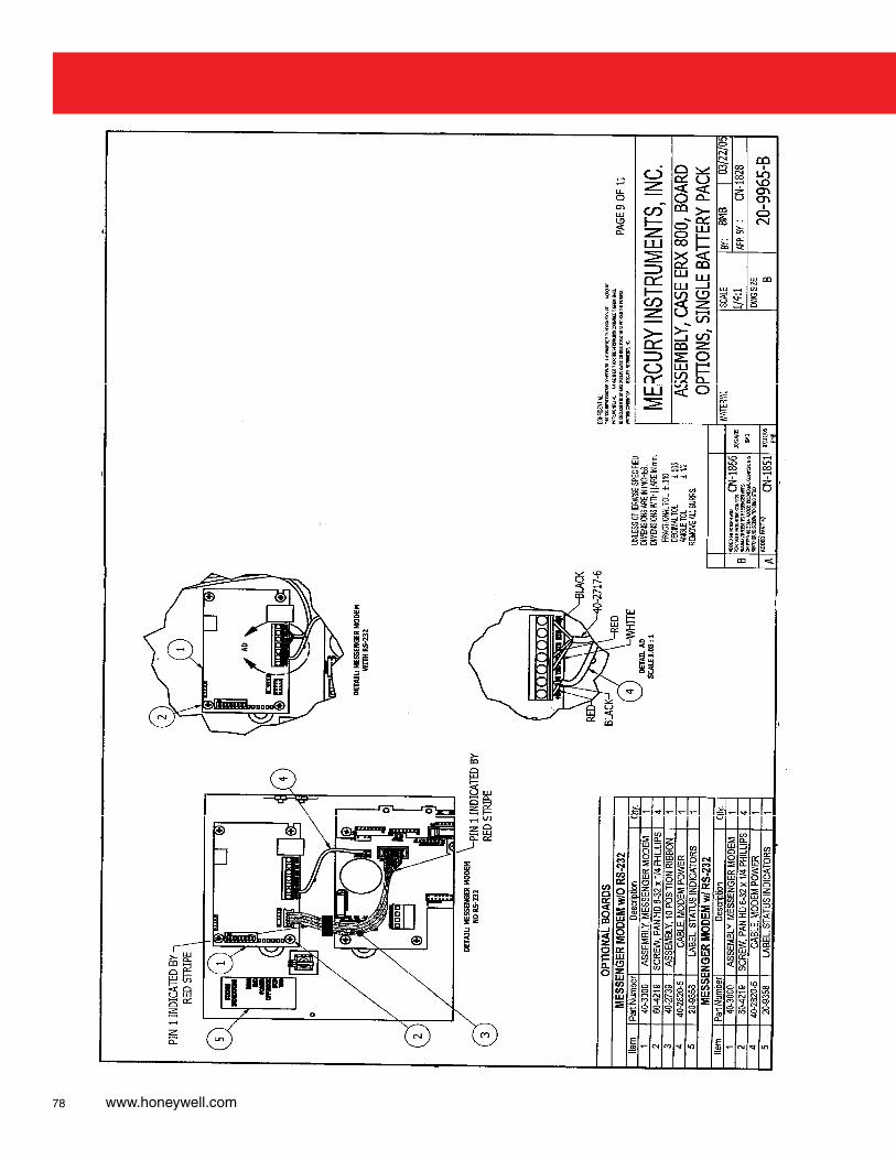
78 www.honeywell.com
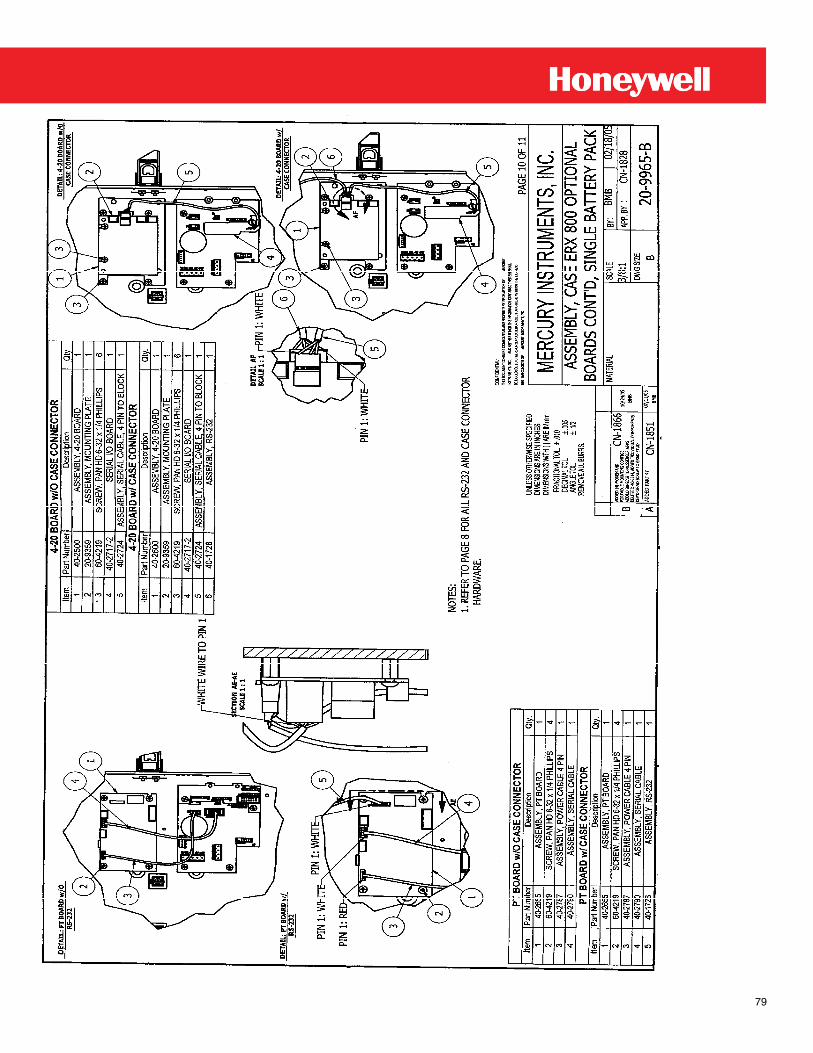
79
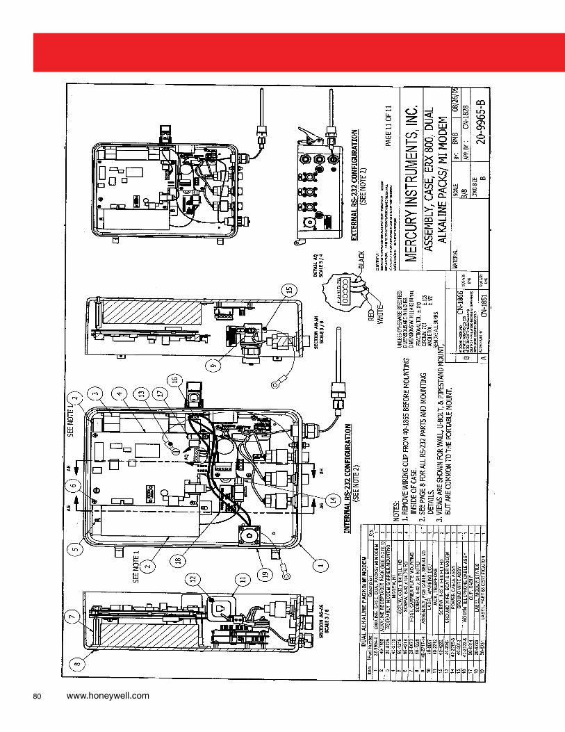
80 www.honeywell.com
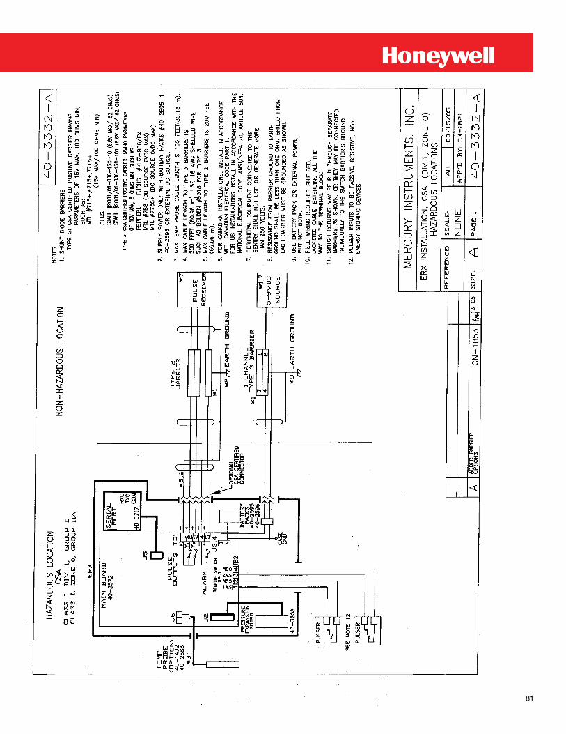
81
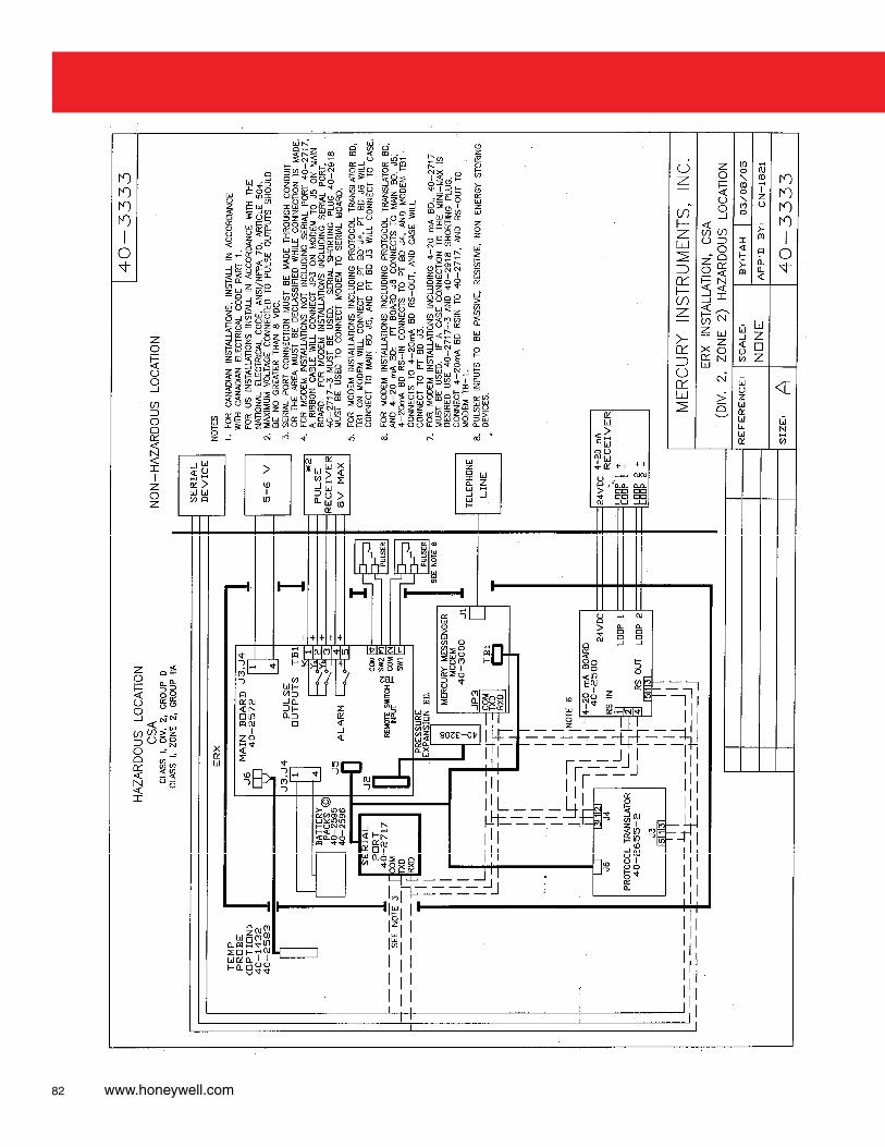
82 www.honeywell.com

83

MNL-ERX-1October 2010 © 2010 Honeywell
Find Out More:To learn more aboutMercury Instruments products, contact your Honeywell Process Solutions representative, visit www.mercuryinstruments.com or call 513-272-1111. Automation and Control SolutionsHoneywell Process Solutions3940 Virginia Ave.Cincinnati, OH 45227513-272-1111 www.honeywell.com