Embed Size (px)
Citation preview
SERVICE INFORMA nON .............................. 3-2
MAINTENANCE SCHEDULE ......... .......... ...... 3-4
FUEL LINE ...................................................... 3-6
THROTILE OPERATION ·· ·· ····· ·· ·· ·· ····· ············ 3-6
AIR CLEANER······················ ········· ·· ····· ··· ······· · 3-7
SPARK PLUG ...................... ........................... 3-8
VALVE CLEARANCE········· ···· ··· ··· ··· ················ 3-9
ENGINE OIL··· ··············································· 3-10
ENGINE OIL STRAINER SCREEN ............ ... 3-12
ENGINE OIL CENTRIFUGAL FILTER··········· 3-12
ENGINE IDLE SPEED ··················· ·· ·············· 3-13
3. MAINTENANCE
DRIVE CHAIN ···· ···· ···················· ········· ·· ·· ·· ·· ··· 3-13
DRIVE CHAIN SLIDER ·································· 3-15
BRAKE SHOE WEAR ·············· ····· ···· ············· 3-15
BRAKE SYSTEM ··········································· 3-16
CLUTCH SYSTEM········································· 3-17
SIDE STAND ························ ····· ·· ····· ···· ········· 3-17
SUSPENSION ·············································· ·3-18
SPARK ARRESTER ······································· 3-19
NUTS, BOLTS, FASTENERS ······ ·· ······ ·········· 3-19
WHEELS/TIRES ································· ······ ··· ·· 3-20
STEERING HEAD BEARINGS ················· ·· ···3-20
3-1
MAINTENANCE
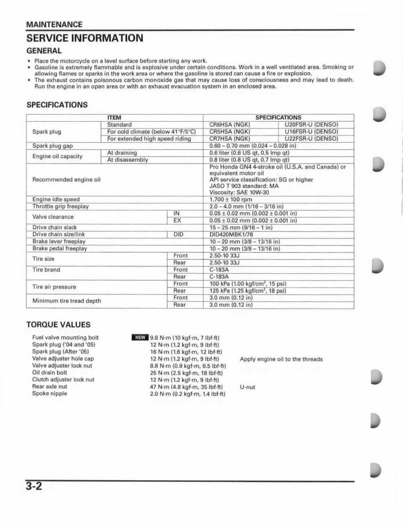
SERVICE INFORMATION GENERAL • Place the motorcycle on 8 level surface before starting any work. • Gasoline is extremely flammable and Is explosive under certain conditions. Work in a well ventilated ares. Smoking or
allowing flames or sparks In the work area or w here the 98801108 is sto red can cause a fi re or explosion . • The exhaust contains poisonous carbon monoxide g8S that may cause loss of consciousness and may lead to death.
Run the engine in an open area or with an exhaust evacuation system in an enclosed area.
SPECIFICATIONS
Spark plug
Engine oil capacity
Recommended engine oit
Valve clearance
Tire size
I I
Tire air pressure
Minimum tire tread depth
TORQUE VALUES
Fuel valve mounting bolt Spark plug ('04 and 'OS) Spark plug (After 'OS) Val .... e adjuster hole cap Valve adjuster lock nut Oil drain boh Clutc::n adjuster lock nut Rear axle nut Spoke nipple
3-2
equivalent motor oil APi service classi fication: SG or higher JASO T 903 standard: MA
" 9.8 N·m (10 kgf·m, 7Ibf·ft ) 12 N·m (1.2 kgf·m, 9 Ibf.ft ) 16 N·m (1.6 kgf·m, 12Ibf·ft) 12 N·m (1 .2 kgf·m. 9Ibf.ft) 8.8 N'm (0.9 kgf·m, 6.5 Ibf·ft) 25 N·m (2.5 kgf·m, 18 Ibf·ft ) 12 N'm (1.2 kgf·m, 9Ibf.ft) 47 N·m 14.8 kgf·m, 35 Ibf·ft) 2.0 N·m (0.2 kgf·m, 1.4Ibf·ft)
SAE
Apply engine oil to the threads
U·nut
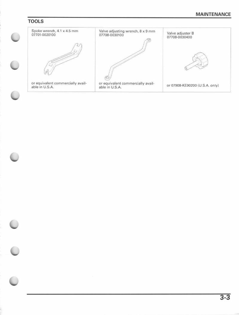
TOOLS
Spoke wrench, 4.1 x 4.5 mm 0770'-0020100
or equivalent commercially available in U.S.A.
Valve adjusting wrench, 8 x 9 mm 07708-0030100
'" or equivalent commercially available in U.S.A.
MAINTENANCE
Valve adjuster B 07708-0030400
or 07908-KE90200 {U .S.A. only)
3-3
MAINTENANCE
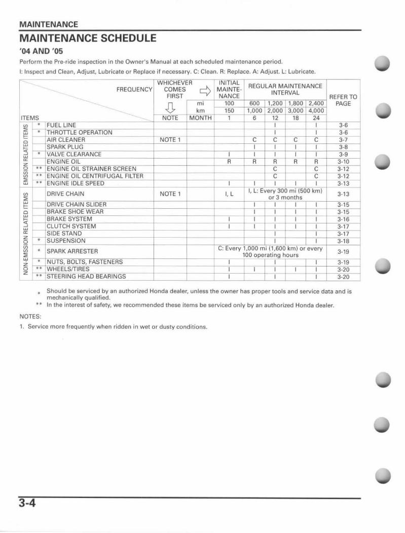
MAINTENANCE SCHEDULE '04 AND '05 Perform the Pre-ride inspection in the Owner's Manual at each scheduled maintenance period.
I: Inspect and Clean, Adjust, Lubricate or Replace if necessary. C: Clean. R: Replace. A: Adjust. L: Lubricate.
ITEMS ~ ~ 'Ut' ~ , rLE
O f- ~
en DRIVE CHAIN
~ ~CHAJN: g IBRAKE
::! ~~1f!,; ~ ~= ~ . " w ~ '--I ----l~=rs. ~z---,-I_ •• • . S~
CTER
, COMES FIRST
.[l. NOTE
NOrE
NOTE 1
, c:> MAINTENANCE
mi km ----* 1
'. L
REGULAR MAINTENANCE INTERVAL '. '~1 4~
c
, , C
', -- '
, C
,
'. L, ev~;!" , m'e""" ,m, , " , : , ,
,
, , , -I- '
REFER TO PAGE
3-. 3-7
3-9
.-----
3-13
3-15
3·19
3-20
Should be serviced by an authorized Honda dealer, unless the owner has proper tools and service data and is mechanically qualified.
.. In the interest of safety, we recommended these items be serviced only by an authorized Honda deater.
NOTES:
,. Service more frequent ly when ridden in wet or dusty conditions.
3-4
MAINTENANCE
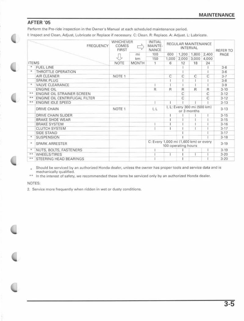
AFTER '05 Perform the Pre-ride inspection in the Owner 's Manual al each scheduled maintenance period.
I: Inspect and Clean, Adjust. Lubricate or Replace if necessary. C: Clean. R: Replace. A: Adjust. L: lubricate.
WHICHEVER INITIAL FREQUENCY COMES ......J\. MAINTE-
FIRST l.-..y' NANCE .[}. , m;
ITEMS --,-___ _ ___ ~~rl__'N"'O"'"TE r~~T j FUEL LINE r
I-~TiCHRon::;~LE~O~PEEFRliA(fTRIOjjN'- ---==11:: 1-_ .. A:;;IRi: ,CLi_~AgN~E~R~=_ NOTE 1
H
SPARK~lUG _ * VALVE CLEARANCE
ENGINE OIL .... ENGINE OIL STRAINER S CREEN
AL FILTER •• ENGINE OIL CENTAIFUG •• f-NGINE IDLE SPEED r--
DRIVE CHAIN ,
r-- ~~IVE CHAIN SUDER
r-- BRAKE SHOE WEAR BRAKE SYSTEM CLUTCH SYSTEM SIDE STAND
• SUSPENSION
'1= ~TEI I
100 150
1
I R
I
I, L
I I
REGULAR MAINTENANCE INTERVAL
600 1,200 1,800 2,400 1,000 2,000 3,000 , 4,000
6 _ _ '12 18 24 I
I I c c c I C I I I I I I I I I R R R R
C C -C C
1 I I I 1 r--r L: Every 300 mi (SOD km ) or 3 months
1------:--1 I
I I I ; I I (
I I I I I
I I I I
II SPARK ARRESTER ~---+'c
+ : Every 1,000 mi ! 1,600 km) or every
100 operating hours
--+t : I I
, I I I I I I I
• NUTS, BOLTS, FASTENERS
•• WHEEtSfT~IR~E~St:.~~~~ •• STEERING HEAD BEARINGS T
I
I I
I
REFER TO PAGE
3-6
JIJ 3-7 3-8 3-9 3-10 3 - 12~ 3-1~ ---1 3-13
3-13
3-15 31-5--3-16 3-17 3-17 3· 18
3·19
3·19 3-~ 3·20
* Should be serviced by an authorized Honda dealer, unless the owner has proper tools and service data and is mechanically qualified.
*"" In the interest of safety, we recommended these items be serviced only by an authorized Honda dealer.
NOTES:
2. Service more frequently when ridden in wet or dusty conditions.
3-5
MAINTENANCE
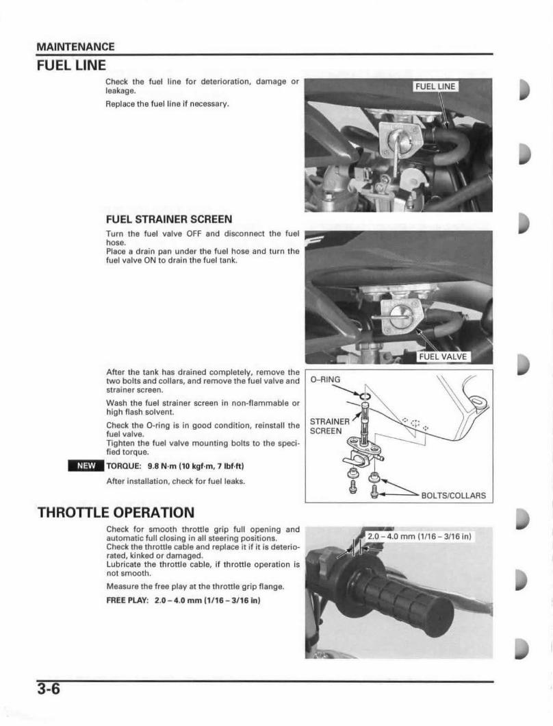
FUEL LINE Check the fuel line for deterioration, damage or leakage.
Replace the fuel line If necessary.
FUEL STRAINER SCREEN Turn the fuel valve OFF and disconnect the fuel hose. Place a drain pan under the fuel hose and turn the fuel valve ON to drain the fuel tank.
After the tank has drained completely, remove the ~1IIIII1IIIII~:::~~~~I11111~=====I11111~ two bolts and collars, and remove the fuel valve and strainer screen.
Wash the fuel strainer screen in non-flammable or high flash solven!.
Check the D-ring is In good condition, reinstall the fuel valve. TIghten the fuel valve mounting bolts to the specified torque.
-:m'TORQUE: 9.8 N'm (10 kgf·m, 7lbf.ftj
After Installation, check for fuellsaks.
THROTTLE OPERATION
3-6
Check for smooth throttle grip full opening and automatic full closing in all steering positions. Check the throttle cable and replace it if it is deteriorated, kfnked or damaged. Lubricate the throttle cable, If throttle operation is not smooth.
Measure the free play al the throttle grip flange.
FREE PLAY: 2.0 - 4.0 mm ' 1' 16 - 3'16 inl
STRAINER SCREEN
11~ BOLTS/COLLARS
mmI1l1S-311Sin)
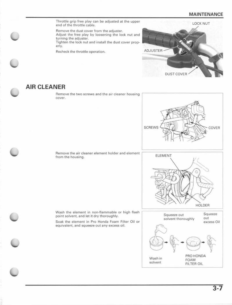
Throttle grip free play can be adjusted at the upper end of the throttle cable.
Remove the dust cover from the adjuster, Adjust the free play by loosening the lock nUl and turning the adjuster. Tighten the lock nut and install the dust cover properly.
Recheck the throttle operation.
AIR CLEANER Remove the two screws and the air cleaner housing cover.
MAINTENANCE
DUSTCQVER
SCREWS COVER
Remove the air cleaner element holder and element ;:==================:::; from the housing. ELEMENT
HOLDER
Wash the element in non-flammable or high flash ~==='-'==========:s:q:u:e:e:,:e=~ point solvent, and let it dry thoroughly. Squeeze out
solvent thoroughly out Soak the element in Pro Honda Foam Filter Oil o r excess Oil equivalent, and squeeze out any excess oil.
Wash in solvent
PRO HONDA FOAM FILTER OIL
3-7
MAINTENANCE
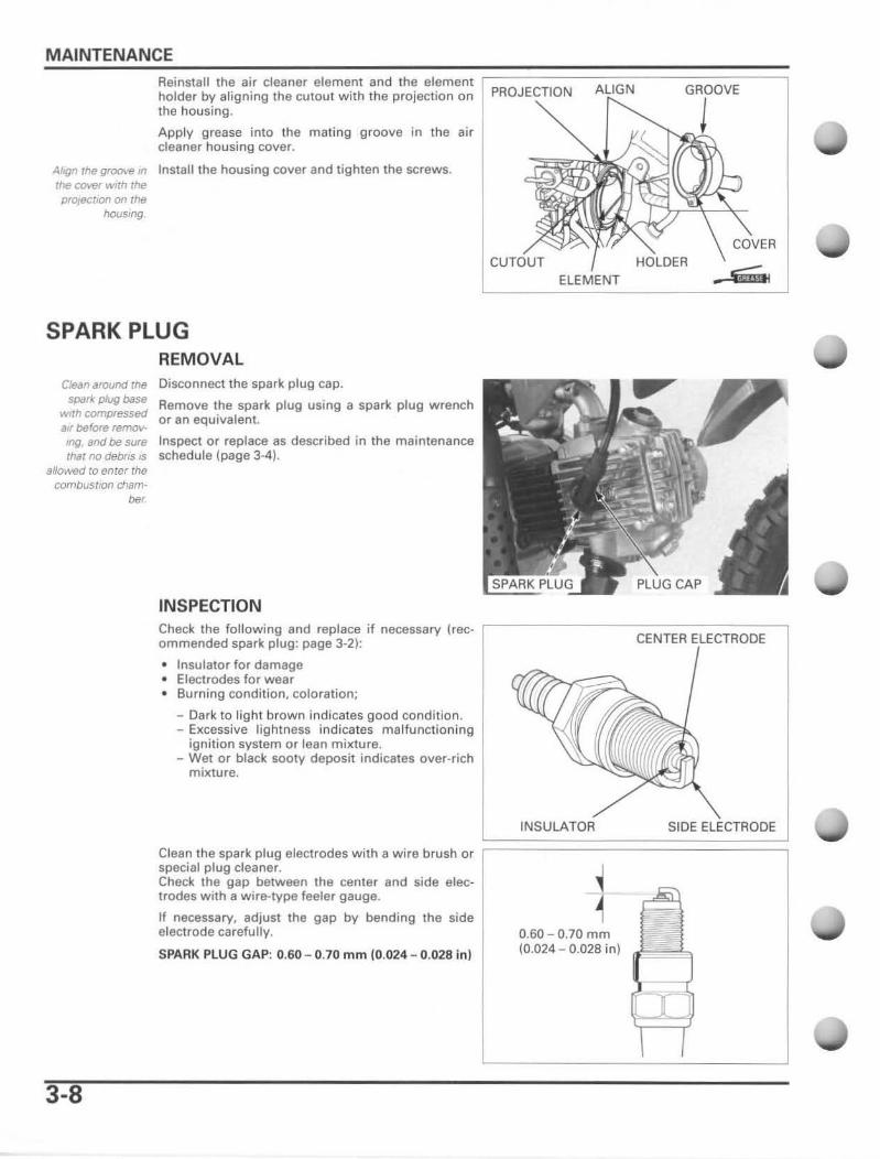
Reinstall the air cleaner element and the element holder by aligning the cutout with the projection on the housing .
Apply grease into the mating groove in the air cleaner housing cover.
AI,gn rhegro<Ne In Install the housing cover and lighten the screws. the cover with the proJe<:tlOfl on the
housmg
SPARK PLUG REMOVAL
Clean "round the spark. plug base
WIth comfjTessed alf before removmg, and be sure that no debns 15
8/1owed to enter the combus/1OfI cham
be,
Disconnect the spark plug cap.
Remove the spark plug using a spark plug wrench or an equivalent.
Inspect or replace as described in the maintenance schedule (page 3·4) .
INSPECTION
PROJECTION GROOVE
ELEMENT
Check the following and replace if necessary (rec- ,-------------------, ommended spark plug: page 3-2): CENTER ELECTRODE
3-8
• Insulator for damage • Electrodes for wear • Burning condition, coloration;
- Dark to light brown indicates good condition. - Excessive lightness indicates malfunctioning
ignition system or lean mixture. - Wet or black sooty deposit indicates over-rich
mixture.
I===~'N~S~U~LA~T~O~R~======~S~'D~E~~~~~ Clean the spark plug electrodes with a wire brush or ~ special plug cleaner. Check the gap between the center and side electrodes with a wire-type feeler gauge.
If necessary, adjust the gap by bending the side electrode carefully.
SPARK PLUG GAP: 0.60 - 0.70 mm (0 .024 - 0.028 in)
0.60 - 0.70 mm (0.024 - 0.028 in)
To prevent damage to the cylmder
head. handtighten the spark. plug befOf8 usmg B
wrench to tighten to /he sf}8CIfl8d
torque.
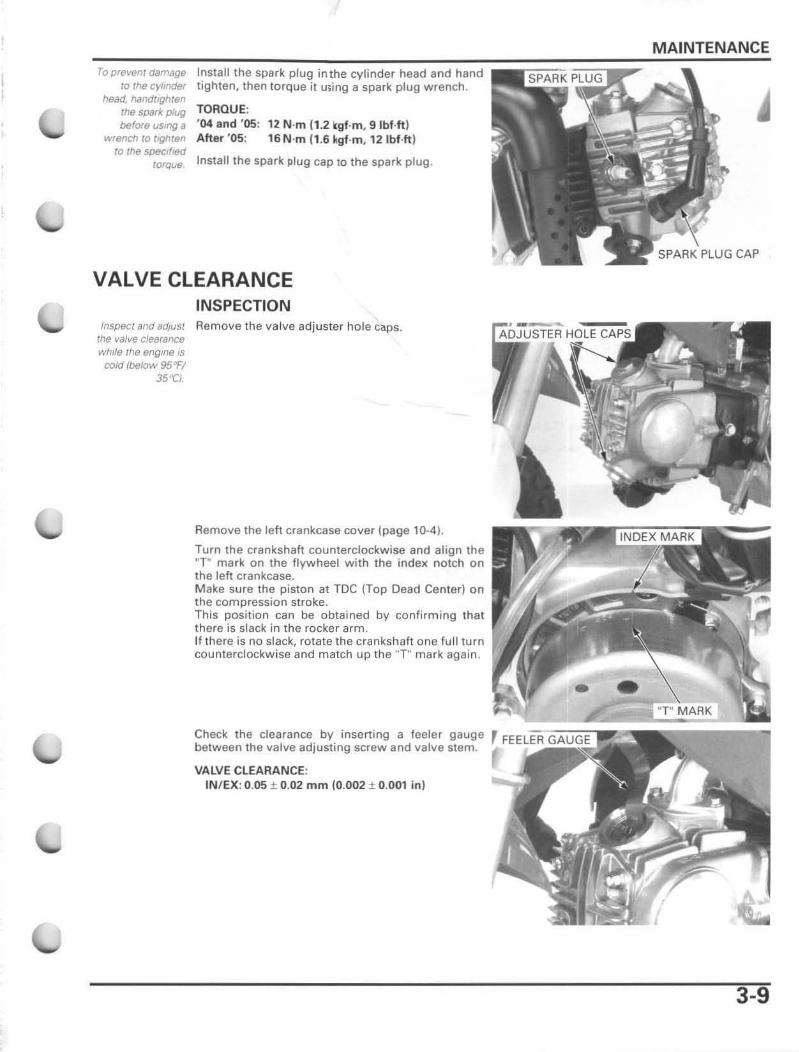
Install the spark plug inthe cylinder head and hand tigh ten. then torque it wing a spark plug wrench .
TORQUE: '04 and 'OS: 12 N·m (1.2 kgf·m. 9 IbUt) After 'OS: 16 N 'm (1.6 kgf·m. 12 IbHt)
Install the spark plug cap to the spark plug.
VALVE CLEARANCE INSPECTION
InspeCf and adluSt Remove the valve adjuster hole Cllps. the valve clearance while the engine IS
cold (below 95"F/ 35"CI
Remove the left crankcase cover (page 10-4 ).
Turn the crankshaft counterclockwise and align the "T" mark on the flywheel with the index notch on the left crankcase. Make sure the piston at TOe (Top Dead Center) on the compression stroke. This position can be obtained by confirming that there is slack in the rocker arm. If there is no slack. rotate the crankshaft one lu l l turn counterclockwise and match up the "r' mark again .
Check the clearance by inserting a feeler gauge between the valve adjusting screw and valve stem.
VALVE CLEARANCE; IN/ EX: 0.05 ± 0.02 mm (0.002 ± 0.001 in )
MAINTENANCE
3-9
MAINTENANCE
ADJUSTMENT
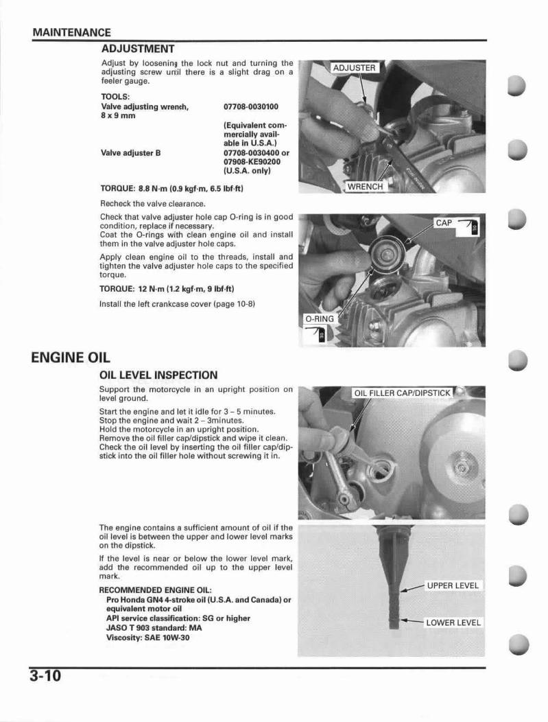
Adjust by loosanin9 the lock nut and turning the rl"'i{.~ru-Si'E;'] adjusting screw un:iI there is a slight drag on a feeler gauge.
TOOLS: Valve adjusting wrench, 8x9mm
Valve adjuster B
07708·0030100
(Equivalent commerciallyavailable in U.S.A.) 07708-0030400 or 07908-KE90200 (U.S.A. only)
TORQUE: 8.8 N'm (0.9 kgf·m, 6.5 Ibf.ft)
Recheck the valve clearance.
Check that valve adjuster hole cap O-ring is in good condition, replace if necessary. Coal the D-rings with clean engine oil and install them in the valve adjuster hole caps.
Apply clean engine oil to the threads, insta ll and tighten the valve adjuster hole caps to the specified torque.
TORQUE: 12 N'm 11.2 kgf-m, Slbf.ft)
Install the left crankcase cover (page 10-8)
ENGINE OIL
3-10
OIL LEVEL INSPECTION Support the motorcycle in an upright position on level ground.
Start the engine and let it idle for 3 - 5 minutes. Stop the engine and wait 2 - 3minutes. Hold the motorcycle in an upright pOSition. Remove the oil filler cap/dipstick and wipe it clean. Check the oil level by inserting the oil filler cap/dipstick into the 011 filler hole without screwing it in.
The engine contains a sufficient amount of oil if the oil level is between the upper and lower level marks on the dipstick.
If the level is near or below the lower level mark, add the recommended oil up to the upper level mark.
RECOMMENDED ENGINE OU.: Pro Honda GN44-strokeoil IU.S.A. and Canada) or equivalent motor all API service classification : SG or higher JASO T 903 standam: MA Viscosity: SAE 10W-30
UPPER LEVEL
LOWER LEVEL
Change rhe englnB oil Wlfh the engine
warm and the motorcycle on /evt1/
ground to assure complete drBlfJIfIQ.
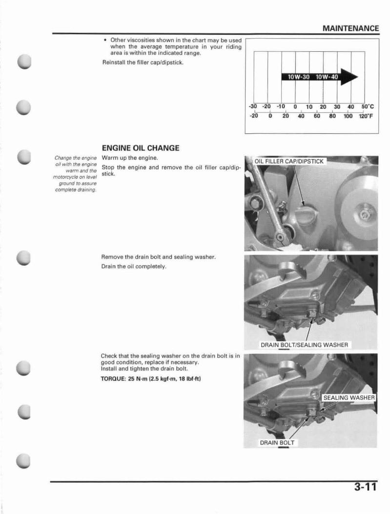
• Other viscosities shown in the chart may be used when the average temperature in your riding Brea is within the indicated range.
Reinstall the filter cap/dipst ick .
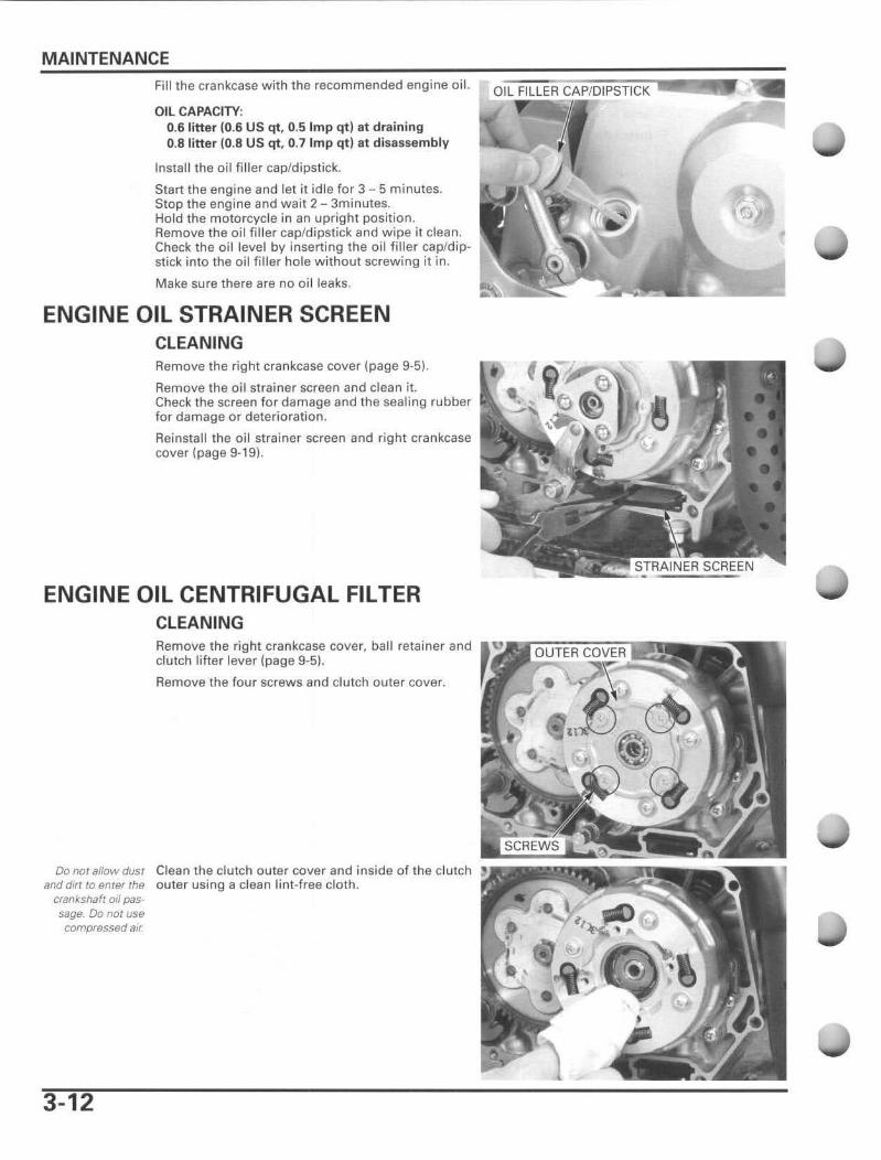
ENGINE OIL CHANGE Warm up the engine.
Stop the engine and remove the oil filler cap/dipstick.
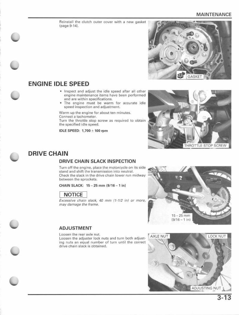
Remove the drain bolt and sealing washer.
Drain the all completely.
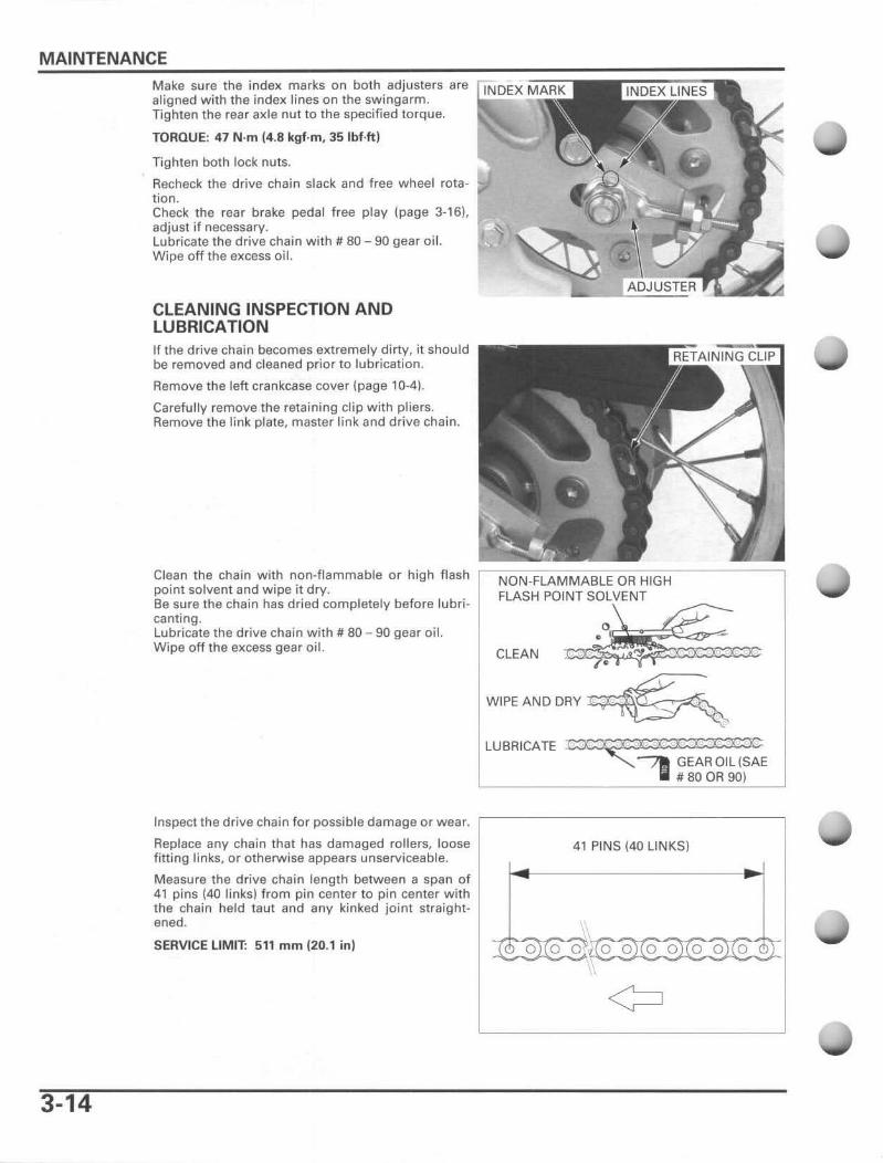
Check that the sealing washer on the drain bolt is in good condition, replace if necessary. Install and tighten the drain bolt.
TORQUE: 25 N 'm (2.5 kgf·m , 18 Ibf·ft)
MAINTENANCE
, I
80 -20 o 20 40 ,00 t2Q' F
3-11
MAINTENANCE Fill the crankcase with the recommended engine oil.
Oil CAPACITY: 0.6 litter (0.6 US qt, 0.5 Imp qt) at draining O.Blitter (0.8 US qt. 0.7 Imp qt) at disassembly
Install the oil filler cap/dipstick.
Start the engine and let it idle for 3 - 5 minutes. Stop the engine and wait 2 - 3minutes. Hold the moto rcycle in an uprigh t position . Remove the oil filler cap/dipstick and w ipe it clean . Check the oil level by inserting the oil filler cap/dipstick into the oil filler hole without screwing it in.
Make sure there are no oi l leaks.
ENGINE OIL STRAINER SCREEN CLEANING Remove the right crankcase cover (page 9-5) ,
Remove the o i l strainer screen and clean it. Check the screen for damage and the sealing rubber for damage or deterioration.
Reinstall the oil strainer screen and right crankcase cover (page 9-19).
ENGINE OIL CENTRIFUGAL FILTER CLEANING Remove the right crankcase cover, ball retainer and clutch li fter lever (page 9-5).
Remove the four screws and clutch outer cover.
Do not allow dust Clean the clutch outer cover and inside of the clutch and dirt to enter the outer using a clean lint-free cloth .
crankshaft oil pas-sage. Do not use compressed air
3-12
Reinstall the clutch outer cover with a new gasket (page 9-14).
ENGINE IDLE SPEED • Inspect and adjust the idle speed after all other
engine ma intenance items have been performed and are within specifications .
• The engine must be warm for accurate idle speed inspection and adjustment.
Warm up the engine for about ten minutes. Connect a tachometer. Turn the throttle stop screw as required to obtain the specified idle speed.
IDLE SPEED: 1,700 ± 100 rpm
DRIVE CHAIN DRIVE CHAIN SLACK INSPECTION Turn off the engine, place the motorcycle on its side stand and shift the transmission into neutral. Check the slack in the drive chain lower run midway between the sprockets.
CHAIN SLACK: 15 -25 mm (9/ 16 - 1in)
NOTICE Excessive chain slack, 40 mm (1-112 in) or more, '!~"'-"'111~ may damage the frame.
ADJUSTMENT Loosen the rear a)(le nut. Loosen the adjuster lock nuts and turn both adjusting nuts an equal number of turn until the correct drive chain slack is obtained.
MAINTENANCE
3-13
MAINTENANCE
3-14
Make sure the index marks on both adjusters are aligned with the index lines on the swingarm. Tighten the rear axle nUllO the specified torque.
TORQUE: 47 N'm (4.8 kgf·m, 35Ibf·ft)
Tighten both lock nuts.
Recheck the drive chain slack and free wheel rotation. Check the rear brake pedal free play (page 3-16), adjust if necessary. Lubricate the drive chain with # 80 - 90 gear oil. Wipe off the excess oil.
CLEANING INSPECTION AND LUBRICATION If the drive chain becomes extremely dirty, it should be removed and cleaned prior to lubrication.
Remove the left crankcase cover (page 10-4).
Carefully remove the retaini ng clip with pliers. Remove the link plate, master link and drive chain.
Clean the chain with non-flammable or high flash '~N~O~NO;-;-F~LA--;-;M~M;-;-;A~B~L~E~O~R~H~'G;;-;-;H---------' point solvent and wipe it dry. FLASH POINT SOLVENT Be sure the chain has dried completely before lubri- ~~ canting. Lubricate the drive chain with # 80 - 90 gear oil. 0 _ Wipe off the excess gear oil. CLEAN ~ 4~
WIPE AND DRY ~ LUBRICATE ~E
Inspect the drive chain for possible damage or wear.
Replace any chain that has damaged rollers, loose filting links, or otherwise appears unserviceable.
Measure the drive chain length between a span of 41 pins (4D links) from pin center to pin center with the chain held taut and any kinked joint straightened.
SERVICE LIMIT: 51' mm (20.1 in) :r, oRo
41 PINS (40 LINKS)
o~Ro oRo oRo oRo or
¢
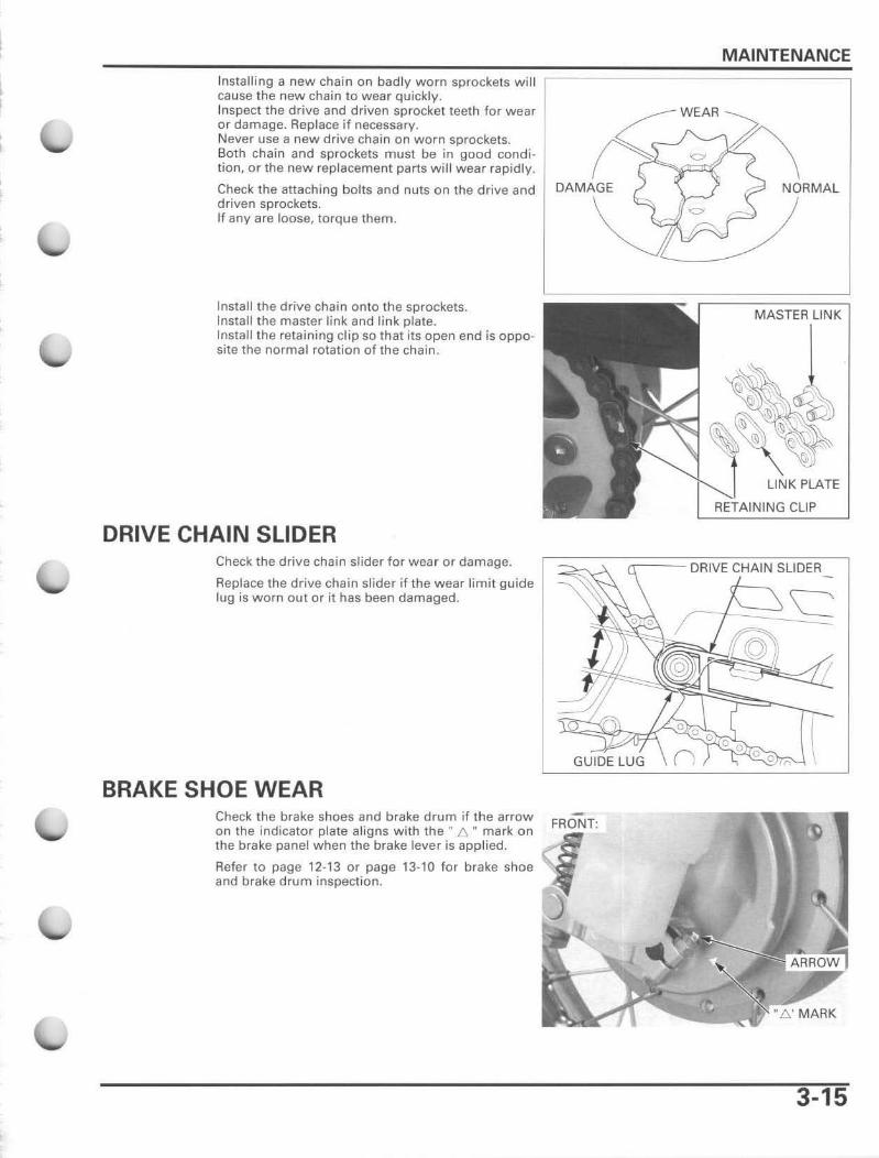
Installing a new chai n on badly worn sprockets w i ll cause the new chain to wear quickly. Inspect the drive and driven sprocket teeth for wear or damage. Replace if necessary. Never use a new drive chain on worn sprockets. Both chain and sprockets must be in good condition, or the new replacement parts will wear rapidly.
Check the attaching bolts and nuts on the drive and driven sprockets. If any are loose, torque them.
Install t he drive chain onto the sprockets. Install the master link and link plate. Install the retaining clip so that its open end is opposite the normal rotation of the chain .
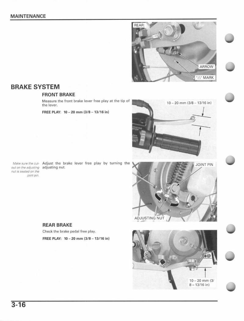
DRIVE CHAIN SLIDER Check the drive chain slider for wea r or damage.
Replace the drive cha in slider if the wear limi t guide lug is worn out or it has been damaged.
BRAKE SHOE WEAR Check t he brake shoes and brake drum if the arrow on the indicator plate aligns with the H 6. " mark on the brake panel when the brake lever is appl ied.
Refer to page 12-13 or page 13-10 for brake shoe and brake drum inspection.
MAINTENANCE
NORMAL
MASTER LINK
CLIP
GUIDE lUG
3-15
MAINTENANCE
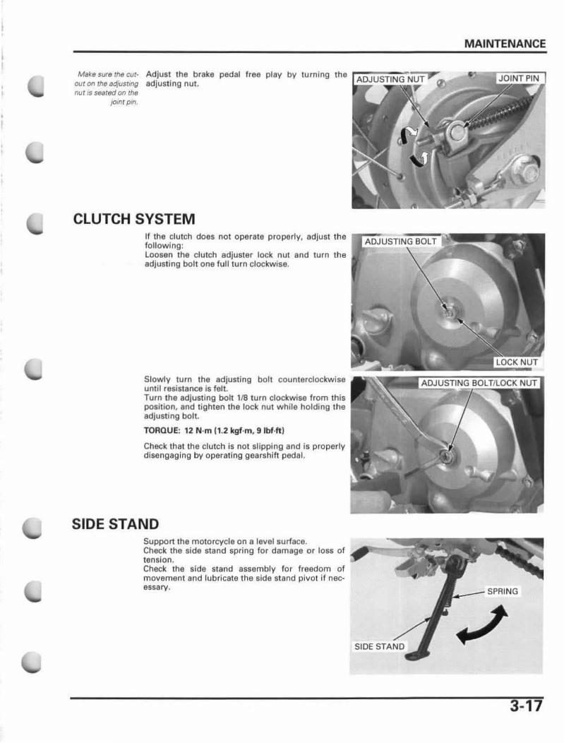
BRAKE SYSTEM FRONT BRAKE Measure the front brake lever free play at the tip of the lever.
FREE PLAY: 10 - 20 mm (3/8 - 13/16 in )
Mak.e sure the cut- Adjust the brake lever free play by turning the our on the adjusting adjusting nut. nUlls seared on the
lomt pm
REAR BRAKE Check the brake pedal free play.
FREE PLAY: 10 - 20 mm (3/8 - 13/ 16 in)
3-16
.~
10 - 20 mm (3/8 - 13/16 in)
\
JOINT PIN
10-20mm(3/ 8 - 13/16 in)
Make sure rhe cur- Adjust the brake pedal free play by turning the out on theadjustmg adjust ing nut. nut IS !)6artKi on the
}Omt p in.
CLUTCH SYSTEM
MAINTENANCE
If the clutch does not operate properly, adjust the r~~;u.STI'N!iio.:il~ following: loosen the clutch adjuster lock nut and turn the adjust ing bolt one full turn clockwise.
Slowly turn the adjusting bolt counterclockwise unlil resistance is felt. Turn the adjusting bolt 118 turn clockwise from this position, and tighten the lock nut while holding the adjusting bolt.
TORQUE! 12 N·m (1.2 kgf .m, 9 Ibf·ft )
Check that the clutch is not slipping and is properly disengaging by operating gearshift pedal.
SIDE STAND Support the motorcycle on a level surface. Check the side stand spring for damage or loss of tension . Check the side stand assembly for freedom of movement and lubricate the side stand pivot if necessary. _ _ _ SPRING
SIDE Sr..ND
3-17
MAINTENANCE
SUSPENSION
3-18
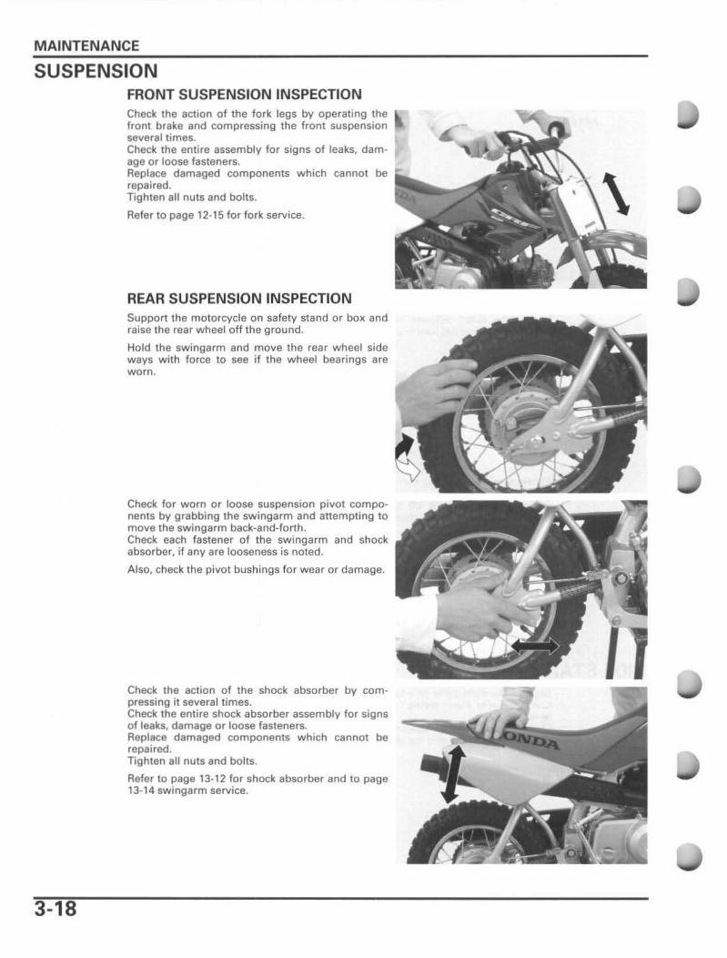
FRONT SUSPENSION INSPECTION Check the action of the fork legs by operating the front brake and compressing the front suspension several limes. Check the entire assembly for signs of leaks, damage or loose fasteners. Replace damaged components which cannot be repaired . Tighten all nuts and bolts.
Refer to page 12·15 for fork service.
REAR SUSPENSION INSPECTION Support the motorcycle on safety stand or box and raise the rear wheel off the ground.
Hold the swingarm and move the rear wheel side ways with force to see if the wheel bearings are worn.
Check for worn or loose suspension pivot components by grabbing the swingarm and attempting to move the swing arm back-and-forth. Check each fastener of the swingarm and shock absorber, if any are looseness is noted.
Also, check the pivot bushings for wear or damage.
Check the action of the shock absorber by compressing it several times. Check the entire shock absorber assembly for signs of leaks, damage or 10058 fasteners. Replace damaged components which cannot be repaired. Tighten all nuts and bolts.
Refer to page 13-12 for shock absorber and to page 13· 14 swingarm service.
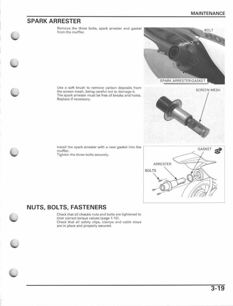
SPARK ARRESTER Remove the three bolts, spark arrester and gasket from the muffler.
Use a soft brush to remove carbon deposits from the screen mesh, being careful not to damage it. The spark arrester must be free of breaks and holes. Replace if necessary.
MAINTENANCE
SCREEN MESH
Install the spark arrester with a new gasket into the r~~~~~~~~~~~~-G'--ACS-KCECT:--!:!-~C---' muffler. IIiijjjIII
Tighten the three bolts securely.
NUTS, BOLTS, FASTENERS Check that all chassis nuts and bolts are tightened to their correct torque values (page 1-10). Check that all safety clips, clamps and cable stays afe in place and properly secured.
ARRESTER
3-19
MAINTENANCE
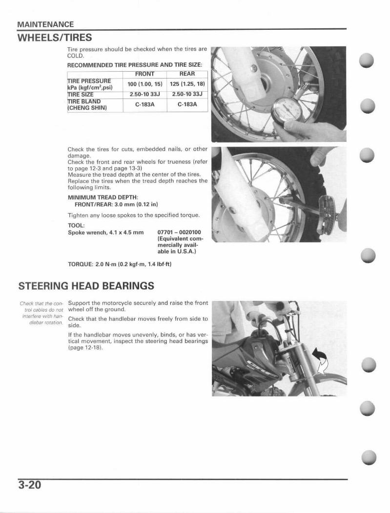
WHEELS/TIRES Tire pressure should be checked when the tires are COLO.
RECOMMENDED TIRE PRESSURE AND TIRE SIZE: R-aNT
IR-r-P~£S"S Pa {kgf/cm2,psij 100 (l .OQ, 15) 125 (1 .25, 18)
RrsTZE -1 2:"Sb:-fo 33 RnOiNon- --+--"''-'--''-'''-'--+ = '--''-'''-'---
CHENG SHIN) C-183A C· l83A
Check the tires for cuts, embedded nails, or other damage. Check the f ront and rear wheels for trueness (refer to page 12-3 and page 13-3) Measure the tread depth al the center of the tires. Replace the tires when the tread depth reaches the following limits.
MINIMUM TREAD DEPTH: FRONT/ REAR: 3.0 mm (0,12 in)
Tighten any loose spokes to the specified torque.
TOOL: Spoke wrench, 4.1)( 4.5 mm 07701 - 0020100
(Equivalent com· merciallyavailable in U.S.A.)
TORQUE: 2.0 N·m (0.2 kgf·m , 1.4Ibf.ft)
STEERING HEAD BEARINGS
Check that the con- Support the motorcycle securely and raise the front ---... 'r-........ trof cables do not w heel off the ground.
interfere WI th han Check that the handlebar moves freely from side to dlebar rotation. side.
3-20
If the handlebar moves unevenly, binds, or has ver· tical movement, inspect the steering head bearings (page 12·18).