Embed Size (px)
Citation preview
General rights Copyright and moral rights for the publications made accessible in the public portal are retained by the authors and/or other copyright owners and it is a condition of accessing publications that users recognise and abide by the legal requirements associated with these rights.
Users may download and print one copy of any publication from the public portal for the purpose of private study or research.
You may not further distribute the material or use it for any profit-making activity or commercial gain
You may freely distribute the URL identifying the publication in the public portal If you believe that this document breaches copyright please contact us providing details, and we will remove access to the work immediately and investigate your claim.
Downloaded from orbit.dtu.dk on: Apr 11, 2020
Homogeneous optical cloak constructed with uniform layered structures
Zhang, Jingjing; Liu, Liu; Luo, Yu; Zhang, Shuang; Mortensen, N. Asger
Published in:Optics Express
Link to article, DOI:10.1364/OE.19.008625
Publication date:2011
Document VersionPublisher's PDF, also known as Version of record
Link back to DTU Orbit
Citation (APA):Zhang, J., Liu, L., Luo, Y., Zhang, S., & Mortensen, N. A. (2011). Homogeneous optical cloak constructed withuniform layered structures. Optics Express, 19(9), 8625-8631. https://doi.org/10.1364/OE.19.008625
Homogeneous optical cloak constructed with uniform layered structures
Jingjing Zhang,1,*
Liu Liu,1 Yu Luo,
2 Shuang Zhang,
3 and Niels Asger Mortensen
1
1DTU Fotonik - Department of Photonics Engineering, Technical University of Denmark, DK-2800 Kongens Lyngby, Denmark
2The Blackett Laboratory, Department of Physics, Imperial College London, London SW7 2AZ, UK 3School of Physics and Astronomy, University of Birmingham, Birmingham, UK
Abstract: The prospect of rendering objects invisible has intrigued researchers for centuries. Transformation optics based invisibility cloak design is now bringing this goal from science fictions to reality and has already been demonstrated experimentally in microwave and optical frequencies. However, the majority of the invisibility cloaks reported so far have a spatially varying refractive index which requires complicated design processes. Besides, the size of the hidden object is usually small relative to that of the cloak device. Here we report the experimental realization of a homogenous invisibility cloak with a uniform silicon grating structure. The design strategy eliminates the need for spatial variation of the material index, and in terms of size it allows for a very large obstacle/cloak ratio. A broadband invisibility behavior has been verified at near-infrared frequencies, opening up new opportunities for using uniform layered medium to realize invisibility at any frequency ranges, where high-quality dielectrics are available.
©2011 Optical Society of America
OCIS codes: (160.3918) Metamaterials; (230.3205) Invisibility cloaks.
References and links
1. J. B. Pendry, D. Schurig, and D. R. Smith, “Controlling electromagnetic fields,” Science 312(5781), 1780–1782 (2006).
2. U. Leonhardt, “Optical conformal mapping,” Science 312(5781), 1777–1780 (2006). 3. A. Greenleaf, M. Lassas, and G. Uhlmann, “Anisotropic conductivities that cannot be detected by EIT,” Physiol.
Meas. 24(2), 413–419 (2003). 4. D. Schurig, J. J. Mock, B. J. Justice, S. A. Cummer, J. B. Pendry, A. F. Starr, and D. R. Smith, “Metamaterial
electromagnetic cloak at microwave frequencies,” Science 314(5801), 977–980 (2006). 5. J. Li and J. B. Pendry, “Hiding under the carpet: a new strategy for cloaking,” Phys. Rev. Lett. 101(20), 203901
(2008). 6. R. Liu, C. Ji, J. J. Mock, J. Y. Chin, T. J. Cui, and D. R. Smith, “Broadband ground-plane cloak,” Science
323(5912), 366–369 (2009). 7. H. F. Ma and T. J. Cui, “Three-dimensional broadband ground-plane cloak made of metamaterials,” Nat
Commun. 1(3), 1 (2010). 8. J. Valentine, J. Li, T. Zentgraf, G. Bartal, and X. Zhang, “An optical cloak made of dielectrics,” Nat. Mater. 8(7),
568–571 (2009). 9. L. H. Gabrielli, J. Cardenas, C. B. Poitras, and M. Lipson, “Silicon nanostructure cloak operating at optical
frequencies,” Nat. Photonics 3(8), 461–463 (2009). 10. J. H. Lee, J. Blair, V. A. Tamma, Q. Wu, S. J. Rhee, C. J. Summers, and W. Park, “Direct visualization of optical
frequency invisibility cloak based on silicon nanorod array,” Opt. Express 17(15), 12922–12928 (2009), http://www.opticsinfobase.org/abstract.cfm?URI=oe-17-15-12922.
11. T. Ergin, N. Stenger, P. Brenner, J. B. Pendry, and M. Wegener, “Three-dimensional invisibility cloak at optical wavelengths,” Science 328(5976), 337–339 (2010).
12. W. Cai, U. K. Chettiar, A. V. Kildishev, and V. M. Shalaev, “Optical cloaking with metamaterials,” Nat. Photonics 1(4), 224–227 (2007).
13. S. Tretyakov, P. Alitalo, O. Luukkonen, and C. Simovski, “Broadband electromagnetic cloaking of long cylindrical objects,” Phys. Rev. Lett. 103(10), 103905 (2009).
14. I. I. Smolyaninov, V. N. Smolyaninova, A. V. Kildishev, and V. M. Shalaev, “Anisotropic metamaterials emulated by tapered waveguides: application to optical cloaking,” Phys. Rev. Lett. 102(21), 213901 (2009).
#144472 - $15.00 USD Received 18 Mar 2011; revised 9 Apr 2011; accepted 10 Apr 2011; published 19 Apr 2011(C) 2011 OSA 25 April 2011 / Vol. 19, No. 9 / OPTICS EXPRESS 8625
15. U. Leonhardt and T. Tyc, “Broadband invisibility by non-Euclidean cloaking,” Science 323(5910), 110–112 (2009).
16. A. Alù and N. Engheta, “Multifrequency optical invisibility cloak with layered plasmonic shells,” Phys. Rev. Lett. 100(11), 113901 (2008).
17. B. Zhang, T. Chan, and B.-I. Wu, “Lateral shift makes a ground-plane cloak detectable,” Phys. Rev. Lett. 104(23), 233903 (2010).
18. Y. Luo, J. Zhang, H. Chen, L. Ran, B.-I. Wu, and J. A. Kong, “A rigorous analysis of plane-transformed invisibility cloaks,” IEEE Trans. Antenn. Propag. 57(12), 3926–3933 (2009).
19. S. Xi, H. Chen, B. Wu, and J. A. Kong, “One-directional perfect cloak created with homogeneous material,” IEEE Microw. Wireless Compon. Lett. 19(3), 131–133 (2009).
20. X. Xu, Y. Feng, Y. Hao, J. Zhao, and T. Jiang, “Infrared carpet cloak designed with uniform silicon grating structure,” Appl. Phys. Lett. 95(18), 184102 (2009).
21. X. Chen, Y. Luo, J. Zhang, K. Jiang, J. B. Pendry, and S. Zhang, “Macroscopic invisibility cloaking of visible light,” Nat. Commun. 2, 176 (2011).
22. B. Zhang, Y. Luo, X. Liu, and G. Barbastathis, “Macroscopic invisibility cloak for visible light,” Phys. Rev. Lett. 106(3), 033901 (2011).
23. L. Liu, M. Pu, K. Yvind, and J. M. Hvam, “High-efficiency, large-bandwidth silicon-on-insulator grating coupler based on a fully-etched photonic crystal structure,” Appl. Phys. Lett. 96(5), 051126 (2010).
24. V. A. Tamma, J. Blair, C. J. Summers, and W. Park, “Dispersion characteristics of silicon nanorod based carpet cloaks,” Opt. Express 18(25), 25746–25756 (2010), http://www.opticsinfobase.org/oe/abstract.cfm?URI=oe-18-25-25746.
25. W. H. Southwell, “Pyramid-array surface-relief structures producing antireflection index matching on optical surfaces,” J. Opt. Soc. Am. A 8(3), 549–553 (1991).
26. E. B. Grann, M. G. Varga, and D. A. Pommet, “Optimal design for antireflective tapered two-dimensional subwavelength grating structures,” J. Opt. Soc. Am. A 12(2), 333–339 (1995).
1. Introduction
Transformation optics has been proposed as a general technique to design complex electromagnetic media with exotic properties, opening up paths for effectively rerouting light around an object to be concealed [1–3]. Experimental realization of a transformation-based invisibility cloak was first reported in microwave frequencies with metallic metamaterials [4]. Since singular material properties require resonant metamaterials, such cloaks only work in a very narrow frequency range and inevitably suffer from a strong absorption. A number of approaches are proposed to mitigate the material parameter constraints [5–16], among which the idea of carpet cloak [5] wins most attentions. Instead of transforming the cloaked area to a point invisible to our eyes, a carpet cloak disguises the obstacle from light by making it appear like a flat ground plane. The material parameters are nonsingular and can in principle be realized without the need of resonant features. Subsequent experimental realizations of this carpet cloak have been carried out in microwave [6, 7] and optical frequencies [8–11] in both 2D [6, 8–10] and 3D [7, 11] scenarios.
In those implementations of carpet cloaks, a quasi-conformal mapping technique is taken which neglects the anisotropy of parameters, and structures with spatially varying densities are used to achieve the inhomogeous isotropic parameter profiles. However, the spatially variant refractive index represents a complex design process resulting in long implementation cycles. In addition, theoretical work shows that the quasi-conformal mapping for eliminating the anisotropy will result in a lateral shift of the scattered wave, which is comparable to the height of the cloaked object, thereby making the object eventually detectable [17]. Furthermore, the quasi-conformal mapping limits the ratio of the size of the object to that of the cloak, since a large ratio corresponds to large anisotropy of the material parameters, breaking the prerequisite of this approximation. Here, we implement a different type of carpet cloak at optical frequencies employing a nano-structured artificial anisotropic material. The parameters of the cloak are homogeneous and rigorously designed [18–20], thus not compromising the performance of the cloaking. Such a homogeneous cloak has recently been introduced in macroscopic scale based on a natural birefringent crystal and experimentally demonstrated at visible frequencies [21, 22]. However, since the anisotropy of a natural material is usually low and cannot be engineered as desired, the hidden object has to be relatively small compared with the cloak device. In others words, macroscopic objects can only be concealed at the cost of using considerably larger space (orders of magnitude larger than the object itself). This challenge becomes more critical for applications in electronics
#144472 - $15.00 USD Received 18 Mar 2011; revised 9 Apr 2011; accepted 10 Apr 2011; published 19 Apr 2011(C) 2011 OSA 25 April 2011 / Vol. 19, No. 9 / OPTICS EXPRESS 8626
industry, for example, in microcircuits and microsystems, wherein hiding the defects on intricate stencils or masks requires delicate and tiny devices. Our work, which is implemented on a silicon-on-insulator (SOI) platform, introduces a flexible way to address this concern. The high-anisotropic material composing the cloak is obtained by patterning the top silicon layer of an SOI wafer with nano-gratings of appropriate filling factor, which leads to a cloaked area only a few times smaller than the cloak itself. By precisely restoring the path of the reflecting wave from the surface, the cloak creates an illusion of a flat plane for a triangular bump on the surface, hiding its presence over a range of optical frequencies (measured between 1480nm to 1580nm).
2. Theory
The cloak takes a triangular shape as shown in Fig. 1(a). In a background with a
permittivityb , the permittivity tensor of a non-magnetic cloak ( 1 ) for transverse-
magnetic (TM, magnetic field perpendicular to the cloak device) polarization can be expressed as [18]:
2 2
2 2 1
2 1 2 1
2 2 2
2 1 2 1
2 1 2 1
.
1
b
H H H
H H H H D
H H H H
H H D H H D
(1)
where H1 and H2 represent the heights of the obstacle and the cloak, respectively, and D is
half the bottom length of the cloak. The above problem can be diagonalized to 0
0
by
rotating the optical axis by the angle . According to the effective medium theory, the
anisotropic parameters can be realized with alternating layered materials [19, 20] at subwavelength scale. Therefore, appropriately combining two dielectric layers with
permittivities 1 and
2 would yield the material with desired effective permittivity tensors:
1 21r r and 1 2
2 11r r
, where r denotes the filling factor of the
constituent materials. The cloak parameters can be tailored by tuning the filling factor (r) and
the orientation of the layers ( ).
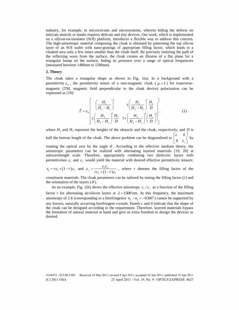
As an example, Fig. 1(b) shows the effective anisotropy / as a function of the filling
factor r for alternating air/silicon layers at 1500 nm. At this frequency, the maximum
anisotropy of 2.6 (corresponding to a birefringence 0.847e on n ) cannot be supported by
any known, naturally occurring birefringent crystals. Panels c and d indicate that the shape of the cloak can be designed according to the requirement. Therefore, layered materials bypass the limitation of natural material at hand and give us extra freedom to design the devices as desired.
#144472 - $15.00 USD Received 18 Mar 2011; revised 9 Apr 2011; accepted 10 Apr 2011; published 19 Apr 2011(C) 2011 OSA 25 April 2011 / Vol. 19, No. 9 / OPTICS EXPRESS 8627
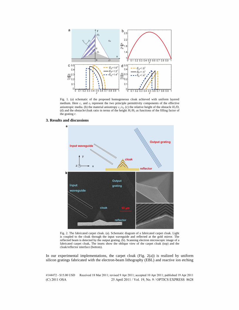
Fig. 1. (a) schematic of the proposed homogeneous cloak achieved with uniform layered
medium. Here ε and ε|| represent the two principle permittivity components of the effective
anisotropic media. (b) the material anisotropy ε/ε||, (c) the relative height of the obstacle H1/D, (d) and the obstacle/cloak ratio in terms of the height H1/H2 as functions of the filling factor of the grating r.
3. Results and discussions
Fig. 2. The fabricated carpet cloak. (a). Schematic diagram of a fabricated carpet cloak. Light is coupled to the cloak through the input waveguide and reflected at the gold mirror. The reflected beam is detected by the output grating. (b). Scanning electron microscopic image of a fabricated carpet cloak, The insets show the oblique view of the carpet cloak (top) and the cloak/reflector interface (bottom).
In our experimental implementations, the carpet cloak (Fig. 2(a)) is realized by uniform silicon gratings fabricated with the electron-beam lithography (EBL) and reactive ion etching
#144472 - $15.00 USD Received 18 Mar 2011; revised 9 Apr 2011; accepted 10 Apr 2011; published 19 Apr 2011(C) 2011 OSA 25 April 2011 / Vol. 19, No. 9 / OPTICS EXPRESS 8628
processes on an SOI wafer (250nm crystalline Si layer on top of a 3 m SiO2 over a bulk Si
substrate). The reflecting surface (the etched side-walls of the yellow region in Fig. 2(a)) is coated with gold. In the vertical direction, the light confinement is achieved with index guiding, and the effective index (2.95) of the guided fundamental mode in the top silicon
layer is used as 1 in the 2D designs. Figure 2(b) shows a scanning electron microscope
image of the cloak device. The bottom width and the height of the cloak are 10 m and
8 m , respectively. The triangular concealed region where objects eventually can be hidden
has a width of 10 m and a height of 1.84 m . A tapered input waveguide is used to guide
the beam towards the cloak at a direction perpendicular to the lateral side of the cloak triangle. The end of the input waveguide has a width of the 6 m and a distance of 5 m
from the cloak. The output beam is diffracted to the vertical direction by a photonic crystal grating coupler [23], and then eventually imaged by an infrared camera in order to observe its pattern. The distance of the grating from the cloak is 24 m . The insets show the oblique
view of the carpet cloak (top) and the cloak/reflector interface (bottom). The period of the gratings composing the cloak is 140nm, and the filling factor r of Si is 0.5. In the measurement, the light with TM polarization from a tunable laser (1480nm to 1580nm) is used to characterize the cloak.
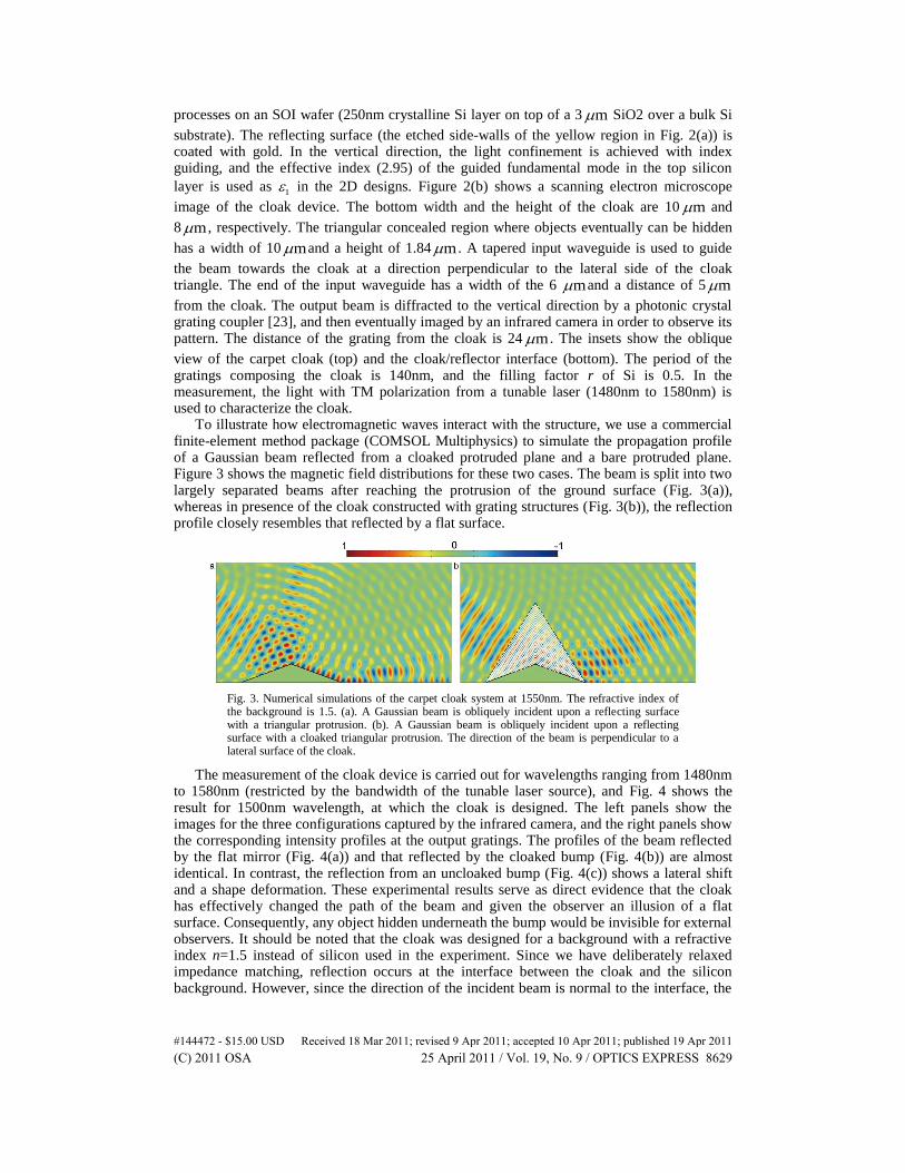
To illustrate how electromagnetic waves interact with the structure, we use a commercial finite-element method package (COMSOL Multiphysics) to simulate the propagation profile of a Gaussian beam reflected from a cloaked protruded plane and a bare protruded plane. Figure 3 shows the magnetic field distributions for these two cases. The beam is split into two largely separated beams after reaching the protrusion of the ground surface (Fig. 3(a)), whereas in presence of the cloak constructed with grating structures (Fig. 3(b)), the reflection profile closely resembles that reflected by a flat surface.
Fig. 3. Numerical simulations of the carpet cloak system at 1550nm. The refractive index of the background is 1.5. (a). A Gaussian beam is obliquely incident upon a reflecting surface with a triangular protrusion. (b). A Gaussian beam is obliquely incident upon a reflecting surface with a cloaked triangular protrusion. The direction of the beam is perpendicular to a lateral surface of the cloak.
The measurement of the cloak device is carried out for wavelengths ranging from 1480nm to 1580nm (restricted by the bandwidth of the tunable laser source), and Fig. 4 shows the result for 1500nm wavelength, at which the cloak is designed. The left panels show the images for the three configurations captured by the infrared camera, and the right panels show the corresponding intensity profiles at the output gratings. The profiles of the beam reflected by the flat mirror (Fig. 4(a)) and that reflected by the cloaked bump (Fig. 4(b)) are almost identical. In contrast, the reflection from an uncloaked bump (Fig. 4(c)) shows a lateral shift and a shape deformation. These experimental results serve as direct evidence that the cloak has effectively changed the path of the beam and given the observer an illusion of a flat surface. Consequently, any object hidden underneath the bump would be invisible for external observers. It should be noted that the cloak was designed for a background with a refractive index n=1.5 instead of silicon used in the experiment. Since we have deliberately relaxed impedance matching, reflection occurs at the interface between the cloak and the silicon background. However, since the direction of the incident beam is normal to the interface, the
#144472 - $15.00 USD Received 18 Mar 2011; revised 9 Apr 2011; accepted 10 Apr 2011; published 19 Apr 2011(C) 2011 OSA 25 April 2011 / Vol. 19, No. 9 / OPTICS EXPRESS 8629
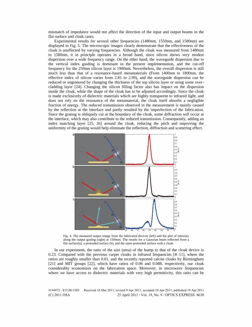
mismatch of impedance would not affect the direction of the input and output beams in the flat surface and cloak cases.
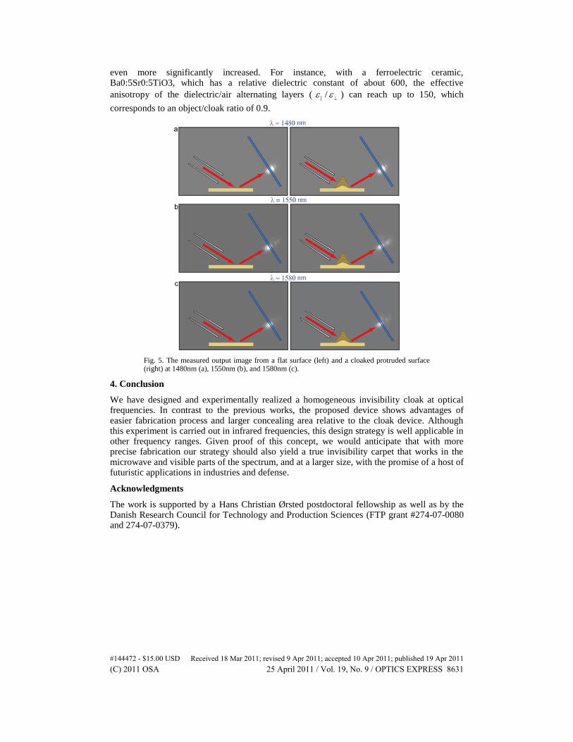
Experimental results for several other frequencies (1480nm, 1550nm, and 1580nm) are displayed in Fig. 5. The microscopic images clearly demonstrate that the effectiveness of the cloak is unaffected by varying frequencies. Although the cloak was measured from 1480nm to 1580nm, it in principle operates in a broad band, since silicon shows very modest dispersion over a wide frequency range. On the other hand, the waveguide dispersion due to the vertical index guiding is dominant in the present implementation, and the cut-off frequency for the 250nm silicon layer is 1900nm. Nevertheless, the overall dispersion is still much less than that of a resonance-based metamaterials (From 1400nm to 1800nm, the effective index of silicon varies from 2.81 to 2.99), and the waveguide dispersion can be reduced or engineered by changing the thickness of the top silicon layer or using some over-cladding layer [24]. Changing the silicon filling factor also has impact on the dispersion inside the cloak, while the shape of the cloak has to be adjusted accordingly. Since the cloak is made exclusively of dielectric materials which are highly transparent to infrared light, and does not rely on the resonance of the metamaterial, the cloak itself absorbs a negligible fraction of energy. The reduced transmission observed in the measurement is mainly caused by the reflection at the interface and partly resulted by the imperfection of the fabrication. Since the grating is obliquely cut at the boundary of the cloak, some diffraction will occur at the interface, which may also contribute to the reduced transmission. Consequently, adding an index matching layer [25, 26] around the cloak, reducing the pitch and improving the uniformity of the grating would help eliminate the reflection, diffraction and scattering effect.
Fig. 4. The measured output image from the fabricated devices (left) and the plot of intensity along the output grating (right) at 1500nm. The results for a Gaussian beam reflected from a flat surface(a), a protruded surface (b), and the same protruded surface with a cloak.
In our experiment, the ratio of the size (area) of the bump to that of the cloak device is 0.23. Compared with the previous carpet cloaks in infrared frequencies [8–11], where the ratios are roughly smaller than 0.01, and the recently reported calcite cloaks by Birmingham [21] and MIT groups [22], which have ratios of 0.06 and 0.088, respectively, our cloak considerably economizes on the fabrication space. Moreover, in microwave frequencies where we have access to dielectric materials with very high permittivity, this ratio can be
#144472 - $15.00 USD Received 18 Mar 2011; revised 9 Apr 2011; accepted 10 Apr 2011; published 19 Apr 2011(C) 2011 OSA 25 April 2011 / Vol. 19, No. 9 / OPTICS EXPRESS 8630
even more significantly increased. For instance, with a ferroelectric ceramic, Ba0:5Sr0:5TiO3, which has a relative dielectric constant of about 600, the effective
anisotropy of the dielectric/air alternating layers ( / ) can reach up to 150, which
corresponds to an object/cloak ratio of 0.9.
Fig. 5. The measured output image from a flat surface (left) and a cloaked protruded surface (right) at 1480nm (a), 1550nm (b), and 1580nm (c).
4. Conclusion
We have designed and experimentally realized a homogeneous invisibility cloak at optical frequencies. In contrast to the previous works, the proposed device shows advantages of easier fabrication process and larger concealing area relative to the cloak device. Although this experiment is carried out in infrared frequencies, this design strategy is well applicable in other frequency ranges. Given proof of this concept, we would anticipate that with more precise fabrication our strategy should also yield a true invisibility carpet that works in the microwave and visible parts of the spectrum, and at a larger size, with the promise of a host of futuristic applications in industries and defense.
Acknowledgments
The work is supported by a Hans Christian Ørsted postdoctoral fellowship as well as by the Danish Research Council for Technology and Production Sciences (FTP grant #274-07-0080 and 274-07-0379).
#144472 - $15.00 USD Received 18 Mar 2011; revised 9 Apr 2011; accepted 10 Apr 2011; published 19 Apr 2011(C) 2011 OSA 25 April 2011 / Vol. 19, No. 9 / OPTICS EXPRESS 8631