Embed Size (px)
DESCRIPTION
mechanical engineering
Citation preview
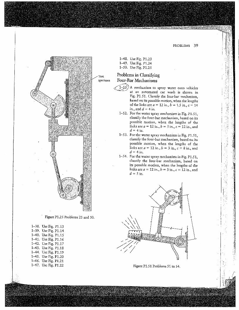
PROBLEMS 39
Figure P1.25 Problems 25 and 50.
1-38. Use Fig. P1.131-39. Use Fig. P1.141-40. Use Fig. P1.151-41. Use Fig. P1.161-42. Use Fig. P1.171-43. Use Fig. Pl.181-44. Use Fig. P1.191-45. Use Fig. P1.201-46. Use Fig. P1.211-47. Use Fig. P1.22
specimen
1-48. Use Fig. P1.231-49. Use Fig. P1.241-50. Use Fig. P1.25
Problems in ClassifyingFour-Bar Mechanisms
~ A mechanism to spray water onto vehiclesat an automated car wash is shown inFig. P1.51. Classify the four-bar mechanism,based on its possible motion, when the lengthsof the links are a = 12 in., b = 1.5 in., c = 14in., and d = 4 in.
1-52. For the water spray mechanism in Fig. P1.51,classify the four-bar mechanism, based on itspossible motion, when the lengths of thelinks are a = 12 in., b = 5 in., c = 12 in., andd= 4in.
1-53.For the water spray mechanism in Fig. P1.51,classify the four-bar mechanism, based on itspossible motion, when the lengths of thelinks are a = 12 in., b = 3 in., c = 8 in., andd = 4in.
1-54. For the water spray mechanism in Fig. P1.51.,classify the four-bar mechanism, based onits possible motion, when the lengths of thelinks are a = 12 in., b = 3 in., c = 12 in., andd= 5in.
Figure P1.51 Problems 51 tO 54.
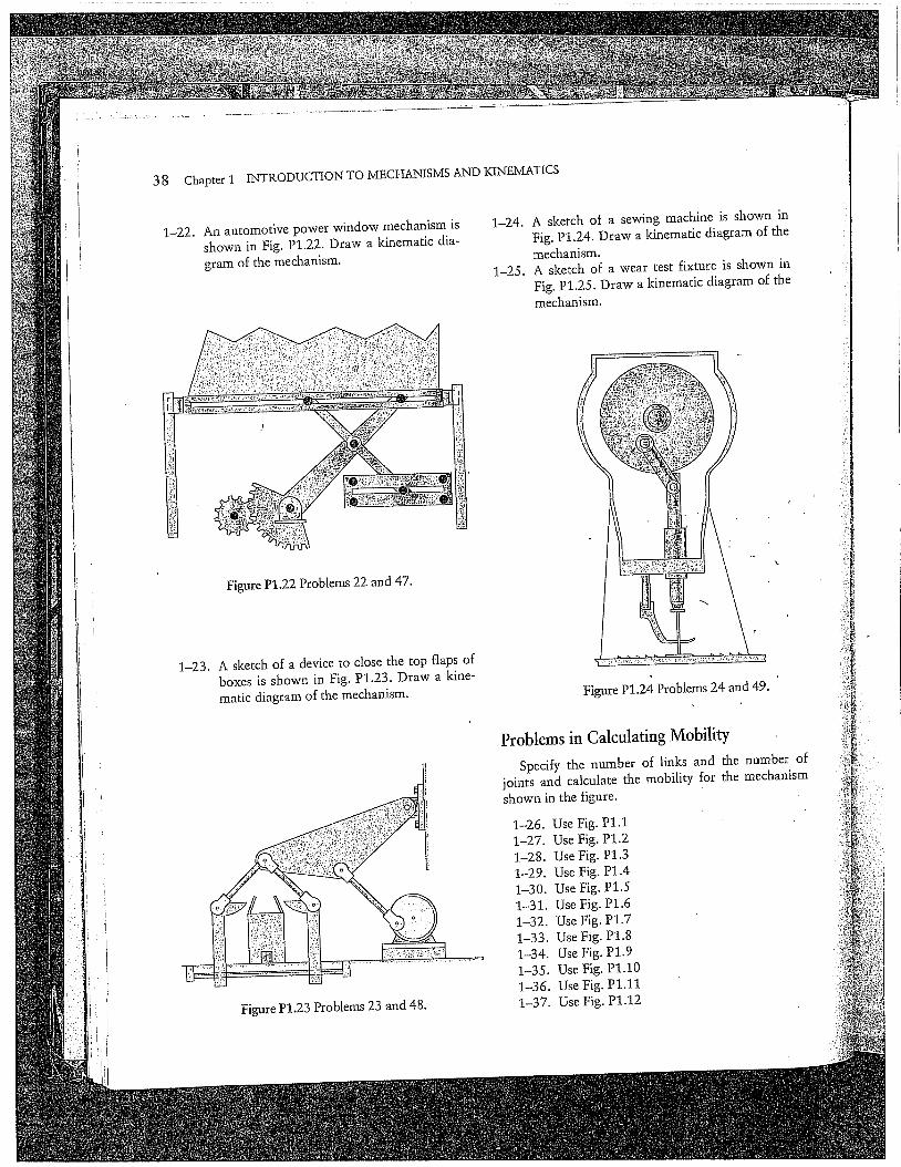
38 Chapter 1 INTRODUCTION TO MECHANISMS AND KINEMATICS
1-22. An automotive power window mechanism isshown in Fig. P1.22. Draw a kinematic dia-gram of the mechanism.
1-24.A sketch of a sewing machine is shown inFig. P1.24. Draw a kinematic diagram of themechanism.
1-25. A sketch of a wear test fixture is shown inFig. P1.25. Draw a kinematic diagram of themechanism.
Figure P1.22 Problems 22 and 47.
1-23. A sketch of a device to close the top flaps ofboxes is shown in Fig. P1.23. Draw a kine-matic diagram of the mechanism.
Figure P1.23 Problems 23 and 48.
Figure P1.24 Problems 24 and 49.
Problems in Calculating MobilitySpecify the number of links and the number of
]oints and calculate the mobility for the mechanismshown in the figure.
1-26. Use Fig. P1.11-27. Use Fig. P1.21-28. Use Fig. P1.31-29. Use Fig. P1.41-30. Use Fig. P1.51-31. Use Fig. P1.61-32. Use Fig. P1.71-33. Use Fig. P1.81-34. Use Fig. P1.91-35. Use Fig. P1.101-36. Use Fig. P1.111-37. Use Fig. Pl.t2
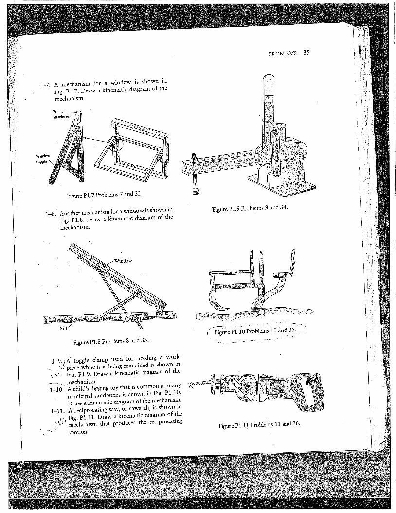
1-7. A mechanism for a window is shown inFig. P1.7. Draw a kinematic diagram of themechanism.
attachment
Window
Figure PI..7 Problems 7 and 32.
1-8.-Another mechanism for a window is shown inFig. P1.8. Draw a Kinematic diagram of themechanism.
Sill
Figure P1.8 Problems 8 and 33.
1-9.iN toggle clamp used for holding a worki’~ piece while it is being machined is shown in
Fig. P1.9. Draw a kinematic diagram of themechanism.
’ 1-10. iA child’s digging toy that is common at many.... municipal sandboxes is shown in Fig. P1.10.
Draw a kinematic diagram of the mechanism.1-11. A reciprocating saw, or saws all, is shown in
ik Fig. P1.11. Draw a kinematic diagram of the
~,.~D) mechanism that produces the reciprocating
motion.
PROBLEMS
Figure P1.9 Problems 9 and 34.
(~ Figure ......PI.IO Problems 10 and(d35.. )
36 Chapter 1 INTRODUCTION TO MECHANISMS AND KINEMATICS
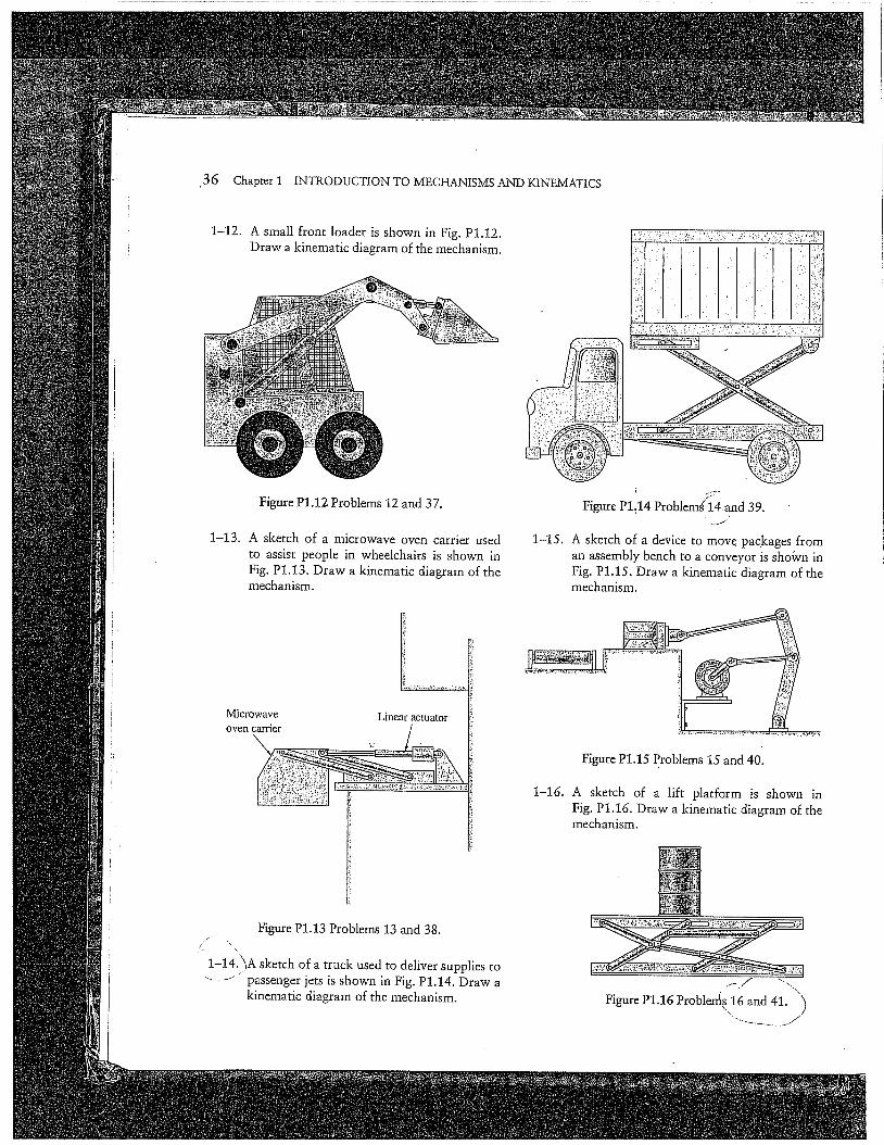
1-12. A small front loader is shown in Fig. P1.12.Draw a kinematic diagram of the mechanism.
Figure Pl.12 Problems 12 and 37.
1-13.A sketch of a microwave oven carrier usedto assist people in wheelchairs is shown inFig. P!.13. Draw a kinematic diagram of themechanism.
Microwaveoven carrier
Linear actuator
1-15.
Figure P1:14 Problemg 14.and 39.
A sketch of a device to move packages froman assembly bench to a conveyor is sho¢vn inFig. P1.15. Draw a kinematic diagram of themechanism.
Figure Pl.15 Problems 15 and 40.
1-16. A sketch of a lift platform is shown inFig. Pl.16. Draw a kinematic diagram of themechanism.
Figure P1.13 Problems 13 and 38.
1-14JhA sketch of a truck used to deliver supplies topassenger jets is shown in Fig. P1.14. Draw akinematic diagram of the mechanism. Figure P1.16 Problemt,s 16 and 41. ")

PROBLEMS 37
1-17.A sketch of a lift platform is shown inFig. Pl.17. Draw a kinematic diagram of themechanism.
Figure Pl.17 Problems 17 and 42.
1-18. ’,A sketch of a backhoe is shown in Fig. P1.18.......... Draw a kinematic diagram of the mechanism.
1-19.
1-20.
Figure P1.18 Problem!..!~..~nd 43.
A sketch of a front loader is shown inFig. P1.19. Draw a kinematic diagram of themechanism.A sketch of an adjustable-height .platformused to load and unload freight trucks isshown in Fig. P1.20. Draw a kinematic dia-gram of the mechanism.A sketch of a kitchen appliance carrier, used forundercounter storage, is shown in Fig. P1.21.Draw a kinematic diagram of the mechanism.
Figure P1.19 Problems 19 and 44. ",,
Figure P1.20 Problems 20 and 45.
Microwaveoven
Counter
Figure P1.21 Problems 21 and 46.