Embed Size (px)
Citation preview
Overview
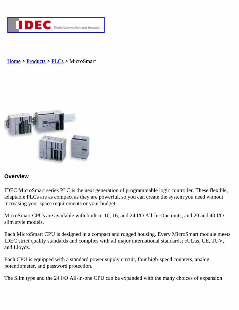
IDEC MicroSmart series PLC is the next generation of programmable logic controller. These flexible, adaptable PLCs are as compact as they are powerful, so you can create the system you need without increasing your space requirements or your budget.
MicroSmart CPUs are available with built-in 10, 16, and 24 I/O All-In-One units, and 20 and 40 I/O slim style models.
Each MicroSmart CPU is designed in a compact and rugged housing. Every MicroSmart module meets IDEC strict quality standards and complies with all major international standards; cULus, CE, TUV, and Lloyds.
Each CPU is equipped with a standard power supply circuit, four high-speed counters, analog potentiometer, and password protection.
The Slim type and the 24 I/O All-in-one CPU can be expanded with the many choices of expansion
Home > Home > Products > Products > PLCs > MicroSmartPLCs > MicroSmart
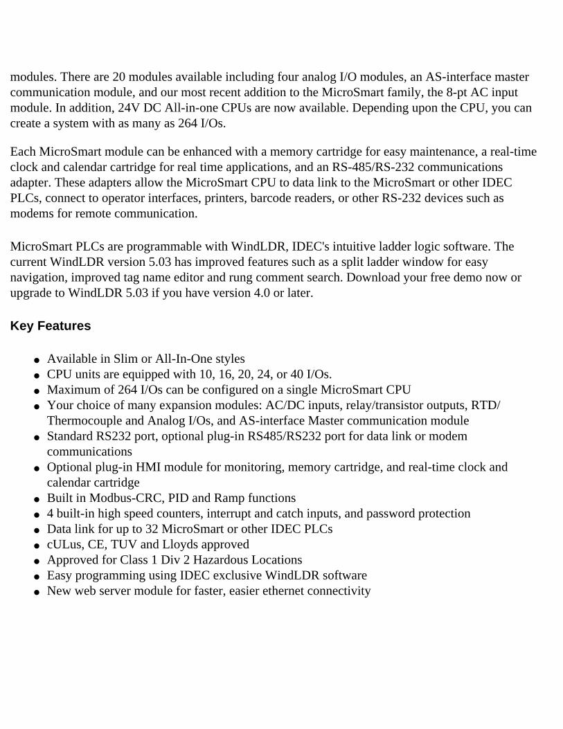
modules. There are 20 modules available including four analog I/O modules, an AS-interface master communication module, and our most recent addition to the MicroSmart family, the 8-pt AC input module. In addition, 24V DC All-in-one CPUs are now available. Depending upon the CPU, you can create a system with as many as 264 I/Os.
Each MicroSmart module can be enhanced with a memory cartridge for easy maintenance, a real-time clock and calendar cartridge for real time applications, and an RS-485/RS-232 communications adapter. These adapters allow the MicroSmart CPU to data link to the MicroSmart or other IDEC PLCs, connect to operator interfaces, printers, barcode readers, or other RS-232 devices such as modems for remote communication.
MicroSmart PLCs are programmable with WindLDR, IDEC's intuitive ladder logic software. The current WindLDR version 5.03 has improved features such as a split ladder window for easy navigation, improved tag name editor and rung comment search. Download your free demo now or upgrade to WindLDR 5.03 if you have version 4.0 or later.
Key Features
● Available in Slim or All-In-One styles ● CPU units are equipped with 10, 16, 20, 24, or 40 I/Os.● Maximum of 264 I/Os can be configured on a single MicroSmart CPU ● Your choice of many expansion modules: AC/DC inputs, relay/transistor outputs, RTD/
Thermocouple and Analog I/Os, and AS-interface Master communication module ● Standard RS232 port, optional plug-in RS485/RS232 port for data link or modem
communications● Optional plug-in HMI module for monitoring, memory cartridge, and real-time clock and
calendar cartridge ● Built in Modbus-CRC, PID and Ramp functions ● 4 built-in high speed counters, interrupt and catch inputs, and password protection ● Data link for up to 32 MicroSmart or other IDEC PLCs ● cULus, CE, TUV and Lloyds approved ● Approved for Class 1 Div 2 Hazardous Locations ● Easy programming using IDEC exclusive WindLDR software ● New web server module for faster, easier ethernet connectivity
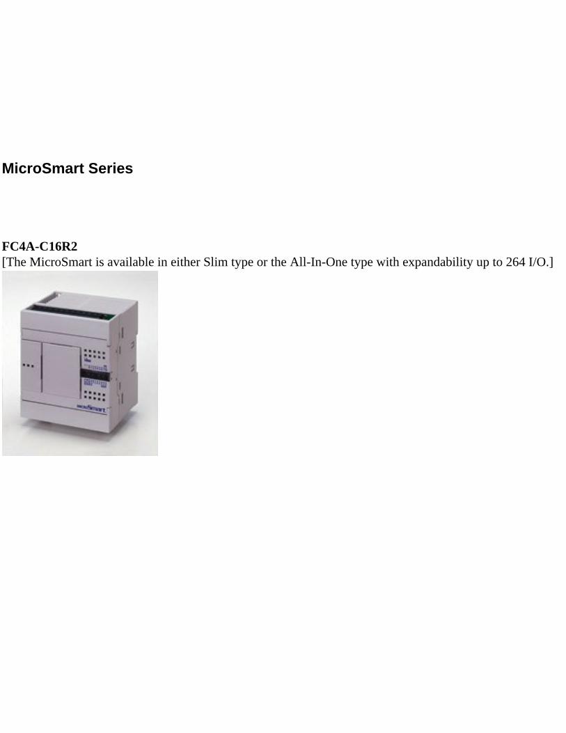
MicroSmart Series
FC4A-C16R2[The MicroSmart is available in either Slim type or the All-In-One type with expandability up to 264 I/O.]
Product Specifications
PLC Product Category CPU Unit
Operating Voltage 120V AC, 240V AC
High Speed Counter(s) 20kHz, 5kHz
High Speed Counter Input Type Sink, Source
RS485 Ports 1, Separate Module Required
On Board Communication Port 1 RS-232
Memory Card Slot Yes
On Board Input Type Transistor Sink, Transitor Source
On Board Output Type Relay
I/O Expandable No
Maximum I/O 16
On Board I/O 9/7
Real Time Clock Yes, Separate Module Required
Connector Type Screw Terminal
NotesMicroSmart All-in-One Brick Style PLC. See catalog pages for further information.
I/O Range Requirement 24 or less
Floating Point Math No
Data Processing 16 Bit
Max. Communication Ports 1, 2
MicroSmart Series
8
PLC
sO
pera
tor
Inte
rfac
esA
utom
atio
n S
oftw
are
Pow
er S
uppl
ies
Sen
sors
Com
mun
icat
ion
& N
etw
orki
ng
Programmable Logic Controllers
MicroSmart Performance
Features:Available in 10, 16, 20, 24, and 40 I/O CPUs.
PID Controls-Program up to 14 PID loops
High Speed I/O-Built-in 4 high speed inputs-Single or Dual Phase-Max. 20KHz frequency
Built-in 2 High speed outputs (Slim model only)
Confi gure up to 264 I/O Points
Data link up to 32 MicroSmart and Pentra CPUs
Using RS485 communication module/port, you can create a network of up to 32 CPUs.
Worldwide Approvals-cULus listed, CE marked-Class 1 Div. 2 for hazardous locations-Lloyds Registered and ABS approved for shipping industry
•
•
•
•
•
•
•
•
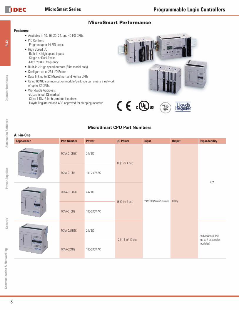
MicroSmart CPU Part Numbers
All-in-One
Appearance Part Number Power I/O Points Input Output Expandability
FC4A-C10R2C 24V DC
10 (6 in/ 4 out)
24V DC (Sink/Source) Relay
N/A
FC4A-C10R2 100-240V AC
FC4A-C16R2C 24V DC
16 (9 in/ 7 out)
FC4A-C16R2 100-240V AC
FC4A-C24R2C 24V DC
24 (14 in/ 10 out)88 Maximum I/O (up to 4 expansion modules)
FC4A-C24R2 100-240V AC
MicroSmart Series
24
PLC
sO
pera
tor
Inte
rfac
esA
utom
atio
n S
oftw
are
Pow
er S
uppl
ies
Sen
sors
Com
mun
icat
ion
& N
etw
orki
ng
Programmable Logic Controllers
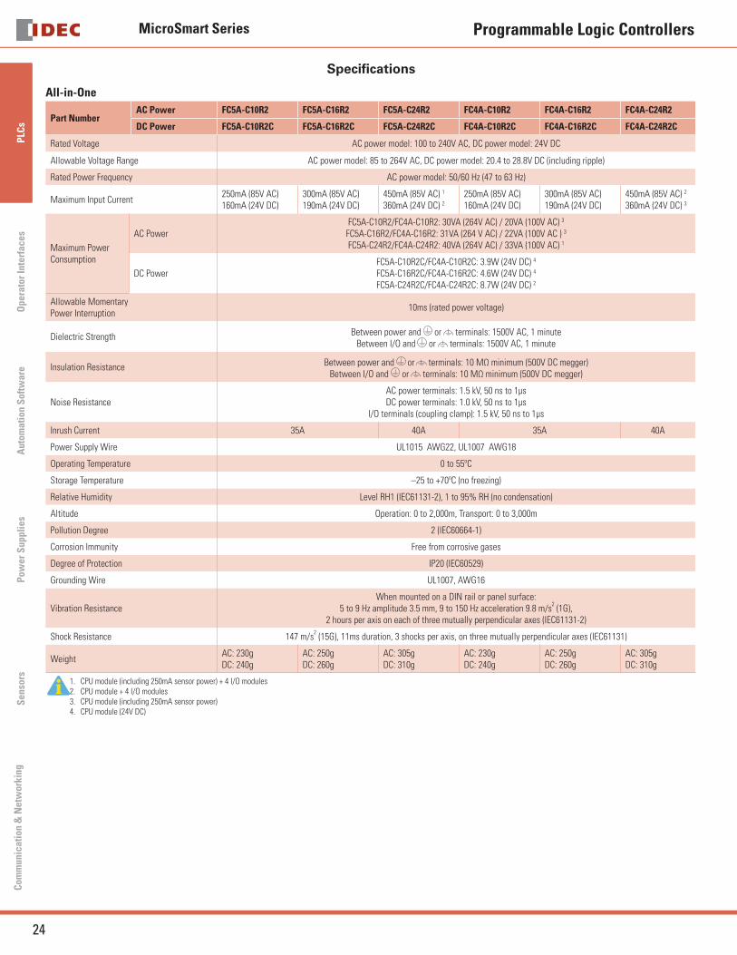
Specifi cations
All-in-One
Part NumberAC Power FC5A-C10R2 FC5A-C16R2 FC5A-C24R2 FC4A-C10R2 FC4A-C16R2 FC4A-C24R2
DC Power FC5A-C10R2C FC5A-C16R2C FC5A-C24R2C FC4A-C10R2C FC4A-C16R2C FC4A-C24R2C
Rated Voltage AC power model: 100 to 240V AC, DC power model: 24V DC
Allowable Voltage Range AC power model: 85 to 264V AC, DC power model: 20.4 to 28.8V DC (including ripple)
Rated Power Frequency AC power model: 50/60 Hz (47 to 63 Hz)
Maximum Input Current250mA (85V AC) 160mA (24V DC)
300mA (85V AC)190mA (24V DC)
450mA (85V AC) 1
360mA (24V DC) 2
250mA (85V AC)160mA (24V DC)
300mA (85V AC)190mA (24V DC)
450mA (85V AC) 2
360mA (24V DC) 3
Maximum PowerConsumption
AC PowerFC5A-C10R2/FC4A-C10R2: 30VA (264V AC) / 20VA (100V AC) 3
FC5A-C16R2/FC4A-C16R2: 31VA (264 V AC) / 22VA (100V AC ) 3
FC5A-C24R2/FC4A-C24R2: 40VA (264V AC) / 33VA (100V AC) 1
DC PowerFC5A-C10R2C/FC4A-C10R2C: 3.9W (24V DC) 4 FC5A-C16R2C/FC4A-C16R2C: 4.6W (24V DC) 4
FC5A-C24R2C/FC4A-C24R2C: 8.7W (24V DC) 2
Allowable MomentaryPower Interruption
10ms (rated power voltage)
Dielectric Strength Between power and or terminals: 1500V AC, 1 minuteBetween I/O and or terminals: 1500V AC, 1 minute
Insulation Resistance Between power and or terminals: 10 MΩ minimum (500V DC megger)Between I/O and or terminals: 10 MΩ minimum (500V DC megger)
Noise ResistanceAC power terminals: 1.5 kV, 50 ns to 1μsDC power terminals: 1.0 kV, 50 ns to 1μs
I/O terminals (coupling clamp): 1.5 kV, 50 ns to 1μs
Inrush Current 35A 40A 35A 40A
Power Supply Wire UL1015 AWG22, UL1007 AWG18
Operating Temperature 0 to 55ºC
Storage Temperature –25 to +70ºC (no freezing)
Relative Humidity Level RH1 (IEC61131-2), 1 to 95% RH (no condensation)
Altitude Operation: 0 to 2,000m, Transport: 0 to 3,000m
Pollution Degree 2 (IEC60664-1)
Corrosion Immunity Free from corrosive gases
Degree of Protection IP20 (IEC60529)
Grounding Wire UL1007, AWG16
Vibration ResistanceWhen mounted on a DIN rail or panel surface:
5 to 9 Hz amplitude 3.5 mm, 9 to 150 Hz acceleration 9.8 m/s2 (1G),
2 hours per axis on each of three mutually perpendicular axes (IEC61131-2)
Shock Resistance 147 m/s2 (15G), 11ms duration, 3 shocks per axis, on three mutually perpendicular axes (IEC61131)
WeightAC: 230gDC: 240g
AC: 250gDC: 260g
AC: 305gDC: 310g
AC: 230gDC: 240g
AC: 250gDC: 260g
AC: 305gDC: 310g
1. CPU module (including 250mA sensor power) + 4 I/O modules2. CPU module + 4 I/O modules3. CPU module (including 250mA sensor power)4. CPU module (24V DC)
MicroSmart Series
26
PLC
sO
pera
tor
Inte
rfac
esA
utom
atio
n S
oftw
are
Pow
er S
uppl
ies
Sen
sors
Com
mun
icat
ion
& N
etw
orki
ng
Programmable Logic Controllers
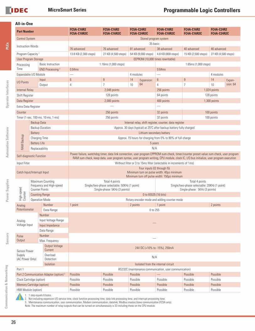
All-in-One
Part NumberFC5A-C10R2FC5A-C10R2C
FC5A-C16R2FC5A-C16R2C
FC5A-C24R2FC5A-C24R2C
FC4A-C10R2FC4A-C10R2C
FC4A-C16R2FC4A-C16R2C
FC4A-C24R2FC4A-C24R2C
Control System Stored program system
Instruction Words35 basic
76 advanced 76 advanced 81 advanced 38 advanced 40 advanced 46 advanced
Program Capacity 1 13.8 KB (2,300 steps) 27 KB (4,500 steps) 54 KB (9,000 steps) 4.8 KB (800 steps) 15 KB (2,500 steps) 27 KB (4,500 steps)
User Program Storage EEPROM (10,000 times rewritable)
ProcessingTime
Basic Instruction 1.16ms (1,000 steps) 1.65ms (1,000 steps)
END Processing 2 0.64ms 0.64ms
Expandable I/O Module — 4 modules — 4 modules
I/O PointsInput 6 9 14 Expansion:
64
6 9 14 Expan-sion: 64Output 4 7 10 4 7 10
Internal Relay 2,048 points 256 points 1,024 points
Shift Register 128 points 64 points 128 points
Data Register 2,000 points 400 points 1,300 points
Extra Data Register — —
Counter 256 points 32 points 100 points
Timer (1-sec, 100-ms, 10-ms, 1-ms) 256 points 32 points 100 points
RAM
Bac
kup
Backup Data Internal relay, shift register, counter, data register
Backup Duration Approx. 30 days (typical) at 25ºC after backup battery fully charged
Battery Lithium secondary battery
Charging Time Approx. 15 hours for charging from 0% to 90% of full charge
Battery Life 5 years
Replaceability N/A
Self-diagnostic Function Power failure, watchdog timer, data link connection, user program EPPROM sum check, timer/counter preset value sum check, user program
RAM sum check, keep data, user program syntax, user program writing, CPU module, clock IC, I/O bus initialize, user program execution
Input Filter Without fi lter or 3 to 15ms fi lter (selectable in increments of 1ms)
Catch Input/Interrupt InputFour inputs (I2 through I5)
Minimum turn on pulse width: 40μs minimumMinimum turn off pulse width: 150μs minimum
Hig
h-sp
eed
Coun
ter
Maximum Counting Frequency and High-speed Counter Points
Total 4 pointsSingle/two-phase selectable: 50KHz (1 point)
Single-phase: 5KHz (3 points)
Total 4 pointsSingle/two-phase selectable: 20KHz (1 point)
Single-phase: 5KHz (3 points)
Counting Range 0 to 65535 (16 bits)
Operation Mode Rotary encoder mode and adding counter mode
AnalogPotentiometer
Number 1 point 2 points 1 point 2 points
Data Range 0 to 255
AnalogVoltage Input
Number
—Input Voltage Range
Input Impedance
Data Range
Pulse Output
Number—
Max. Frequency
Sensor Power Supply (AC Power Only)
Output Voltage Current
24V DC (+10% to -15%), 250mA
Overload Detection
N/A
Isolation Isolated from the internal circuit
Port 1 RS232C (maintenance communication, user communication)
Port 2 Communication Adapter (option) 3 Possible Possible Possible — Possible Possible
Clock Cartridge (option) Possible Possible Possible Possible Possible Possible
Memory Cartridge (option) Possible Possible Possible Possible Possible Possible
HMI Module (option) Possible Possible Possible Possible Possible Possible
1. 1 step equals 6 bytes.2. Not including expansion I/O service time, clock function processing time, data link processing time, and interrupt processing time.3. Maintenance communication, user communication, Modem communication, datalink, Modbus master/slave communication (FC5A only).Note: The maximum number of relay outputs that can be turned on simultaneously is 33 including those on the CPU module.
MicroSmart Series
27
PLC
sO
perator InterfacesA
utomation S
oftware
Pow
er Supplies
Sensors
Com
munication &
Netw
orking
Programmable Logic Controllers
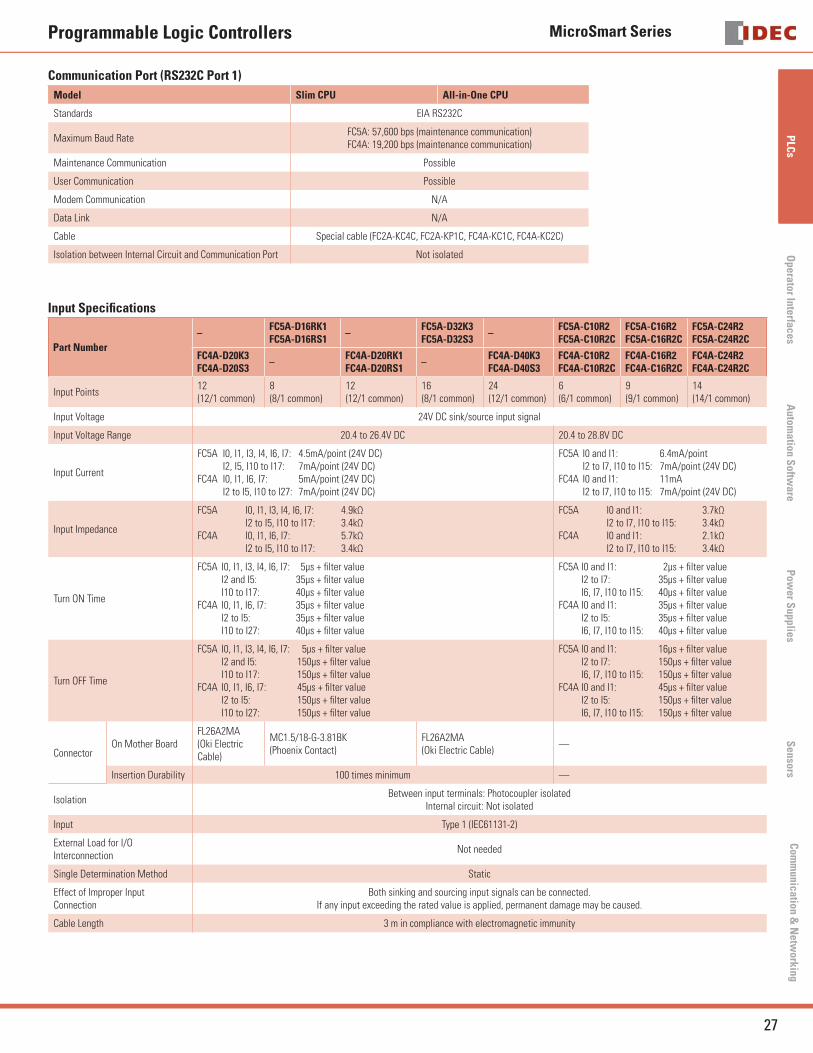
Communication Port (RS232C Port 1)
Model Slim CPU All-in-One CPU
Standards EIA RS232C
Maximum Baud RateFC5A: 57,600 bps (maintenance communication)FC4A: 19,200 bps (maintenance communication)
Maintenance Communication Possible
User Communication Possible
Modem Communication N/A
Data Link N/A
Cable Special cable (FC2A-KC4C, FC2A-KP1C, FC4A-KC1C, FC4A-KC2C)
Isolation between Internal Circuit and Communication Port Not isolated
Input Specifi cations
Part Number
–FC5A-D16RK1FC5A-D16RS1
–FC5A-D32K3FC5A-D32S3
–FC5A-C10R2FC5A-C10R2C
FC5A-C16R2FC5A-C16R2C
FC5A-C24R2FC5A-C24R2C
FC4A-D20K3FC4A-D20S3
–FC4A-D20RK1FC4A-D20RS1
–FC4A-D40K3FC4A-D40S3
FC4A-C10R2FC4A-C10R2C
FC4A-C16R2FC4A-C16R2C
FC4A-C24R2FC4A-C24R2C
Input Points12(12/1 common)
8(8/1 common)
12(12/1 common)
16(8/1 common)
24(12/1 common)
6(6/1 common)
9(9/1 common)
14(14/1 common)
Input Voltage 24V DC sink/source input signal
Input Voltage Range 20.4 to 26.4V DC 20.4 to 28.8V DC
Input Current
FC5A I0, I1, I3, I4, I6, I7: 4.5mA/point (24V DC) I2, I5, I10 to I17: 7mA/point (24V DC)FC4A I0, I1, I6, I7: 5mA/point (24V DC) I2 to I5, I10 to I27: 7mA/point (24V DC)
FC5A I0 and I1: 6.4mA/point I2 to I7, I10 to I15: 7mA/point (24V DC)FC4A I0 and I1: 11mA I2 to I7, I10 to I15: 7mA/point (24V DC)
Input Impedance
FC5A I0, I1, I3, I4, I6, I7: 4.9kΩ I2 to I5, I10 to I17: 3.4kΩFC4A I0, I1, I6, I7: 5.7kΩ I2 to I5, I10 to I17: 3.4kΩ
FC5A I0 and I1: 3.7kΩ I2 to I7, I10 to I15: 3.4kΩFC4A I0 and I1: 2.1kΩ I2 to I7, I10 to I15: 3.4kΩ
Turn ON Time
FC5A I0, I1, I3, I4, I6, I7: 5μs + fi lter value I2 and I5: 35μs + fi lter value I10 to I17: 40μs + fi lter valueFC4A I0, I1, I6, I7: 35μs + fi lter value I2 to I5: 35μs + fi lter value I10 to I27: 40μs + fi lter value
FC5A I0 and I1: 2μs + fi lter value I2 to I7: 35μs + fi lter value I6, I7, I10 to I15: 40μs + fi lter valueFC4A I0 and I1: 35μs + fi lter value I2 to I5: 35μs + fi lter value I6, I7, I10 to I15: 40μs + fi lter value
Turn OFF Time
FC5A I0, I1, I3, I4, I6, I7: 5μs + fi lter value I2 and I5: 150μs + fi lter value I10 to I17: 150μs + fi lter valueFC4A I0, I1, I6, I7: 45μs + fi lter value I2 to I5: 150μs + fi lter value I10 to I27: 150μs + fi lter value
FC5A I0 and I1: 16μs + fi lter value I2 to I7: 150μs + fi lter value I6, I7, I10 to I15: 150μs + fi lter valueFC4A I0 and I1: 45μs + fi lter value I2 to I5: 150μs + fi lter value I6, I7, I10 to I15: 150μs + fi lter value
ConnectorOn Mother Board
FL26A2MA(Oki Electric Cable)
MC1.5/18-G-3.81BK(Phoenix Contact)
FL26A2MA(Oki Electric Cable)
—
Insertion Durability 100 times minimum —
IsolationBetween input terminals: Photocoupler isolated
Internal circuit: Not isolated
Input Type 1 (IEC61131-2)
External Load for I/OInterconnection
Not needed
Single Determination Method Static
Effect of Improper InputConnection
Both sinking and sourcing input signals can be connected.If any input exceeding the rated value is applied, permanent damage may be caused.
Cable Length 3 m in compliance with electromagnetic immunity
MicroSmart Series
28
PLC
sO
pera
tor
Inte
rfac
esA
utom
atio
n S
oftw
are
Pow
er S
uppl
ies
Sen
sors
Com
mun
icat
ion
& N
etw
orki
ng
Programmable Logic Controllers
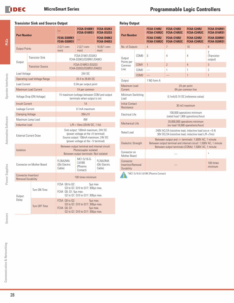
Transistor Sink and Source Output
Part Number
—FC5A-D16RK1FC5A-D16RS1
FC5A-D32K3FC5A-D32S3
FC4A-D20RK1FC4A-D20RS1
—FC4A-D40K3FC4A-D40S3
Output Points2 (2/1 com-mon)
2 (2/1 com-mon)
16 (8/1 com-mon)
Output
Transistor Sink FC5A-D16K1/D32K3
FC4A-D20K3/D20RK1/D40K3
Transistor SourceFC5A-D16RS1/D32S3
FC4A-D20S3/D20RS1/D40S3
Load Voltage 24V DC
Operating Load Voltage Range 20.4 to 28.8V DC
Load Current 0.3A per output point
Maximum Load Current 1A per common
Voltage Drop (ON Voltage)1V maximum (voltage between COM and output
terminals when output is on)
Inrush Current 1A
Leakage Current 0.1mA maximum
Clamping Voltage 39V±1V
Maximum Lamp Load 8W
Inductive Load L/R = 10ms (28.8V DC, 1 Hz)
External Current Draw
Sink output: 100mA maximum, 24V DC(power voltage at the +V terminal)
Source output: 100mA maximum, 24V DC(power voltage at the –V terminal)
IsolationBetween output terminal and internal circuit:
Photocoupler isolatedBetween output terminals: Not isolated
Connector on Mother BoardFL26A2MA(Oki Electric Cable)
MC1.5/16-G-3.81BK(Phoenix Contact)
FL26A2MA(Oki Electric Cable)
Connector Insertion/Removal Durability
100 times minimum
Output Delay
Turn ON Time
FC5A Q0 to Q2: 5μs max. Q3 to Q7, Q10 to Q17: 300μs max.FC4A Q0, Q1: 5μs max. Q2 to Q7, Q10 to Q17: 300μs max.
Turn OFF Time
FC5A Q0 to Q2: 5μs max. Q3 to Q7, Q10 to Q17: 300μs max.FC4A Q0, Q1: 5μs max. Q2 to Q7, Q10 to Q17: 300μs max.
Relay Output
Part Number
FC5A-C10R2FC5A-C10R2C
FC5A-C16R2FC5A-C16R2C
FC5A-C24R2FC5A-C24R2C
FC5A-D16RK1FC5A-D16RS1
FC4A-C10R2FC4A-C10R2C
FC4A-C16R2FC4A-C16R2C
FC4A-C24R2FC4A-C24R2C
FC4A-D20RK1FC4A-D20RS1
No. of Outputs 4 7 10 8
Output Points per Common Line
COM0 3 4 42(Transistor output)
COM1 1 2 4 3
COM2 — 1 1 2
COM3 — — 1 1
Output 1 NO form A
Maximum Load Current
2A per point8A per common line
Minimum Switching Load
0.1mA/0.1V DC (reference value)
Initial Contact Resistance
30 mΩ maximum
Electrical Life100,000 operations minimum
(rated load 1,800 operations/hour)
Mechanical Life20,000,000 operations minimum(no load 18,000 operations/hour)
Rated Load240V AC/2A (resistive load, inductive load cos ø = 0.4)
30V DC/2A (resistive load, inductive load L/R =7ms)
Dielectric Strength Between output and terminals: 1,500V AC, 1 minute
Between output terminal and internal circuit: 1,500V AC, 1 minuteBetween output terminals (COMs): 1,500V AC, 1 minute
Connector on Mother Board
— *
Connector Insertion/Removal Durability
—100 times minimum
*MC1.5/16-G-3.81BK (Phoenix Contact)
MicroSmart Series
42
PLC
sO
pera
tor
Inte
rfac
esA
utom
atio
n S
oftw
are
Pow
er S
uppl
ies
Sen
sors
Com
mun
icat
ion
& N
etw
orki
ng
Programmable Logic Controllers
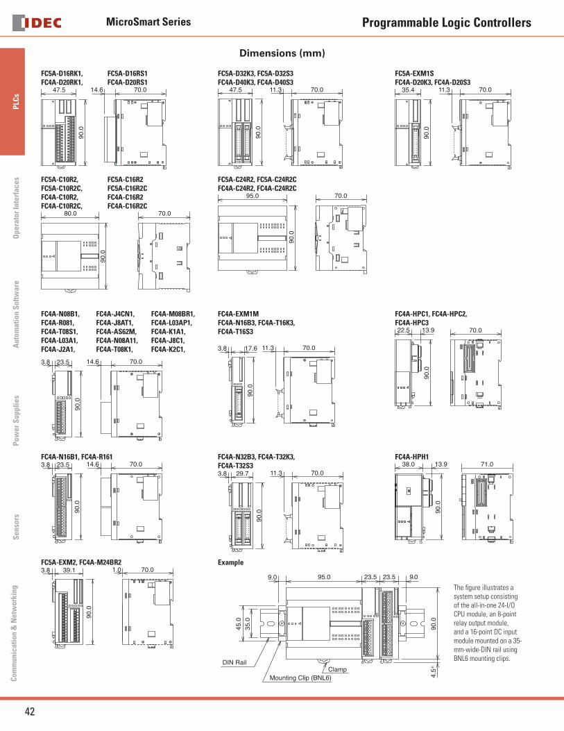
Dimensions (mm)
FC5A-D16RK1, FC5A-D16RS1FC4A-D20RK1, FC4A-D20RS1
47.590
.070.014.6
FC5A-D32K3, FC5A-D32S3FC4A-D40K3, FC4A-D40S3
47.5
90.0
70.011.3
FC5A-EXM1SFC4A-D20K3, FC4A-D20S3
35.4
90.0
70.011.3
FC5A-C10R2, FC5A-C16R2FC5A-C10R2C, FC5A-C16R2CFC4A-C10R2, FC4A-C16R2FC4A-C10R2C, FC4A-C16R2C
90.0
80.0 70.0
FC5A-C24R2, FC5A-C24R2CFC4A-C24R2, FC4A-C24R2C
95.0
90.0
70.0
FC4A-N08B1, FC4A-R081,FC4A-T08S1,FC4A-L03A1,FC4A-J2A1,
FC4A-J4CN1,FC4A-J8AT1,FC4A-AS62M,FC4A-N08A11, FC4A-T08K1,
FC4A-M08BR1,FC4A-L03AP1,FC4A-K1A1,FC4A-J8C1,FC4A-K2C1,
70.014.623.53.8
90.0
FC4A-EXM1MFC4A-N16B3, FC4A-T16K3,FC4A-T16S3
70.011.317.63.8
90.0
FC4A-HPC1, FC4A-HPC2,FC4A-HPC3
70.0
90.0
22.5 13.9
FC4A-N16B1, FC4A-R16170.014.623.53.8
90.0
FC4A-N32B3, FC4A-T32K3,FC4A-T32S3
70.011.329.73.8
90.0
FC4A-HPH171.0
90.0
38.0 13.9
FC5A-EXM2, FC4A-M24BR270.01.039.13.8
90.0
Example
95.0
DIN Rail
Mounting Clip (BNL6)
23.5 23.5 9.09.0
90.0
45.0
35.0
Clamp
4.5∗
The fi gure illustrates a system setup consisting of the all-in-one 24-I/O CPU module, an 8-point relay output module, and a 16-point DC input module mounted on a 35-mm-wide-DIN rail using BNL6 mounting clips.
MicroSmart Series
43
PLC
sO
perator InterfacesA
utomation S
oftware
Pow
er Supplies
Sensors
Com
munication &
Netw
orking
Programmable Logic Controllers
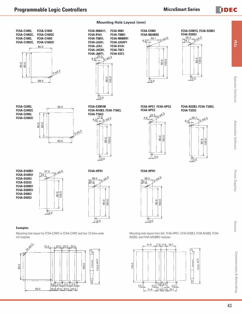
Mounting Hole Layout (mm)
FC5A-C10R2, FC5A-C16R2FC5A-C10R2C, FC5A-C16R2CFC4A-C10R2, FC4A-C16R2FC4A-C10R2C, FC4A-C16R2C
90.0
83.0
68.0
80.0
2-ø4.3
FC4A-N08A11, FC4A-R081FC4A-R161, FC4A-T08K1 FC4A-T08S1, FC4A-M08BR1 FC4A-L03A1, FC4A-L03AP1 FC4A-J2A1, FC4A-K1A1FC4A-J4CN1, FC4A-T8C1FC4A-J8AT1, FC4A-K2C1
23.56.3
3.0
90.0
103.
0
2–ø4.3
FC5A-EXM2 FC4A-M24BR2
39.16.3
3.0
90.0
103.
0
2–ø4.3
FC5A-EXM1S, FC4A-D20K3FC4A-D20S3
103.
090
.0
35.424.1
3.0
2-ø4.3
FC5A-C24R2,FC4A-C24R2CFC4A-C24R2,FC4A-C24R2C
90.0
83.0
83.0
95.0
2-ø4.3
FC5A-EXM1MFC4A-N16B3, FC4A-T16K3,FC4A-T16S3
90.0
103.
0
17.66.3 2–ø4.3
3.0
FC4A-HPC1 FC4A-HPC2FC4A-HPC3
22.54.8
3.090
.010
3.0
2–ø4.3
FC4A-N32B3, FC4A-T32K3, FC4A-T32S3
29.76.3
3.0
90.0
103.
0
2–ø4.3
FC5A-D16RK1FC5A-D16RS1FC5A-D32K3 FC5A-D32S3 FC4A-D20RK1FC4A-D20RS1FC4A-D40K3 FC4A-D40S3 90
.010
3.0
47.524.1 2–ø4.3
3.0
FC4A-HPH1
38.020.3
3.0
90.0
103.
0
2–ø4.3
FC4A-HPH1
38.020.3
3.0
90.0
103.
0
2–ø4.3
Examples
Mounting hole layout for FC5A-C24R2 or FC4A-C24R2 and four 23.5mm-wideI/O modules
23.5 23.5 23.512.3
15.3 23.5 23.5 23.583.0
3.0 3.0 3.0 3.0
103.
0
83.0
10–ø
4.3
113.
0±0
.2
Mounting hole layout from left, FC4A-HPH1, FC4A-D20K3, FC4A-N16B3, FC4A-N32B3, and FC4A-M24BR2 modules
41.8
3.0 3.03.0
3.03.0
41.8 17.6 17.6 29.7
103.
0
17.6 17.6 29.7
113.
0±0
.2
MicroSmart Series
44
PLC
sO
pera
tor
Inte
rfac
esA
utom
atio
n S
oftw
are
Pow
er S
uppl
ies
Sen
sors
Com
mun
icat
ion
& N
etw
orki
ng
Programmable Logic Controllers
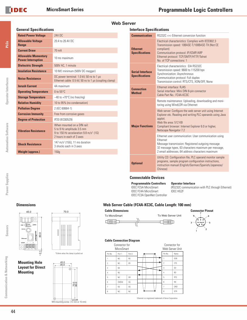
Web Server General Specifi cations
Rated Power Voltage 24V DC
Allowable Voltage Range
20.4 to 26.4V DC
Current Draw 70 mA
Allowable MomentaryPower Interruption
10 ms maximum
Dielectric Strength 500V AC, 1 minute
Insulation Resistance 10 MΩ minimum (500V DC megger)
Noise ResistanceDC power terminal: 1.0 kV, 50 ns to 1 μs Ethernet cable: 0.5 kV, 50 ns to 1 μs (coupling clamp)
Inrush Current 4A maximum
Operating Temperature 0 to 55°C
Storage Temperature –40 to +70°C (no freezing)
Relative Humidity 10 to 95% (no condensation)
Pollution Degree 2 (IEC 60664-1)
Corrosion Immunity Free from corrosive gases
Degree of Protection IP20 (IEC60529)
Vibration Resistance
When mounted on a DIN rail:5 to 9 Hz amplitude 3.5 mm9 to 150 Hz accelaration 9.8 m/s2 (1G)2 hours in each of 3 axes
Shock Resistance147 m/s2 (15G), 11 ms duration3 shocks each in 3 axes
Weight (approx.) 150g
Interface Specifi cations
Communication RS232C <=> Ethernet conversion function
EthernetSpecifi cations
Electrical characteristics: Complies with IEEE802.3Transmission speed: 10BASE-T/100BASE-TX (Not CE compliant)Communication protocol: IP/ICMP/ARPEthernet protocol: TCP/SMTP/HTTP/TelnetNo. of TCP connections: 1
Serial InterfaceSpecifi cations
Electrical characteristics: EIA RS232CTransmission speed: 9600 to 115200 bpsSynchronization: AsynchronousCommunication protocol: Full duplex Transmission control: RTS/CTS, XON/OFF, None
ConnectionMethod
Ethernet interface: RJ45Serial interface: Mini DIN 8-pin connectorCable Part No.: FC4A-KC3C
Major Functions
Remote maintenance: Uploading, downloading and moni-toring using WindLDR via Ethernet
Web server: Confi gure the web server unit using Internet Explorer etc. Reading and writing PLC operands using Java applet.Web fi le area: 512 KBCompliant browser: Internet Explorer 6.0 or higher, Netscape Navigator 7.2
Ethernet user communication: User communication using EthernetMessage transmission: Registered outgoing message32 message types, 63 characters maximum per message, 2 email addresses, 64 address characters maximum
Optional
Utility CD: Confi guration fi le, PLC operand monitor sample programs, sample program confi guration instructions, instruction manual (English/German/Spanish/Japanese/Chinese)
Connectable Devices
Programmable ControllersIDEC FC5A MicroSmartIDEC FC4A MicroSmartIDEC FC3A OpenNet Controller
Operator Interface(RS232C communication with PLC through Ethernet)IDEC HG2F
Dimensions
45.0
80.0
2.1
70.0
∗
*5.6mm when the clamp is pulled out
Mounting Hole Layout for Direct Mounting
45.035.0
80.0
70.0
M4 mounting screw (12 mm or 15 mm)
Web Server Cable (FC4A-KC3C, Cable Length: 100 mm)
Cable Dimensions
To MicroSmart To Web Server Unit
Connector Pinout
Cable Connection Diagram
Ethernet is a registered trademark of Xerox Corporation.
Pin No. Port 1 Port 2
1 NC RS
2 NC ER
3 SD
4 RD
5 NC DR
6 CMSW SG
7 SG SG
8 NC NC
Pin No. Name
1 DSR
2 CTS
3 SD
4 RD
5 RTS
6 NC
7 GND
8 DTR
Connector forMicroSmart
Connector for Web Server Unit