Embed Size (px)
Citation preview
Home Monitoring and Control System
EEC 517 Spring 2008 Term Project
Matthew Dolloff
Department of Electrical and Computer Engineering Cleveland State University
Cleveland, Ohio 44115
May 1, 2008
Page 1 of 47
Table of Contents
Abstract ............................................................................................................................... 2 1 Introduction................................................................................................................. 2 2 Hardware..................................................................................................................... 3
2.1 PICDEM.net 2 Development Board ................................................................... 3 2.2 Sensors ................................................................................................................ 4 2.3 Numerical Keypad .............................................................................................. 4 2.4 Relay and Lamp .................................................................................................. 5
3 Software ...................................................................................................................... 5 3.1 HTML Source Code............................................................................................ 5
3.1.1 System Monitoring...................................................................................... 5 3.1.2 System Control............................................................................................ 6 3.1.3 MPFS2 Utility............................................................................................. 6
3.2 C Source Code .................................................................................................... 6 3.2.1 Microchip TCPIP Stack .............................................................................. 6 3.2.2 Application Specific Code .......................................................................... 7
4 Future Work ................................................................................................................ 9 5 Conclusion .................................................................................................................. 9 6 References................................................................................................................... 9 Appendices........................................................................................................................ 11 Appendix A: Parts List...................................................................................................... 12
Appendix B: Hardware Schematics .............................................................................. 15 Appendix C: File Listing .............................................................................................. 18 Appendix E: Application Specific C Code ................................................................... 21
project.c..................................................................................................................... 21 CustomHTTPApp.c .................................................................................................. 37 HardwareProfile.h ..................................................................................................... 40
Appendix F: Gant Chart of Project Work ..................................................................... 46 Final Presentation.............................................................................................................. 47
Page 2 of 47
Abstract Security monitoring and control of a home or apartment is become more and more commonplace, and perhaps even a necessity, in households today. However the monitoring costs for professional monitoring can be very expensive and provide limited remote control of the system. This project lays the foundation for a self-monitored home alarm and control system. It incorporates real sensors used in home monitoring of windows and doors. It also incorporates a “deterrent” system in the form of a remotely controlled light. There is also a web based interface that allows for the monitoring and control of the system from any device that has a simple web browser and internet access. Use of an LCD provides local feedback about the state of the alarm system.
1 Introduction Home security monitoring and deterrence systems are becoming more and more popular in today’s homes. The increase in home burglaries is a major factor in people’s decision to install these systems. Reference [1] shows that in Dallas, TX home burglaries are up 20% so far in 2008. While this is a larger than normal increase, the FBI has compiled statistics that according to Reference [2] and Reference [3] burglary rates increased 0.5% in 2005 and 1.3% in 2006. While more expensive homes are more likely to be targeted by burglars, there is always desire by all people at all income levels to feel safe in their homes and to feel that their property is safe. Since home monitoring systems can be expensive to have professionally monitored (Reference [4], ADT, has costs at a minimum of $33.99/month) this can potentially be cost prohibitive for some people. In addition, these systems require a landline phone to be monitored remotely by the professional monitoring agencies. Many people are starting to forgo tradition landline phones and use only cell phones. This creates a gap between the monitoring services and the users. Some monitoring systems are starting to use cellular technologies for system monitoring, but this does not work for all users as cellular coverage within a home can sometimes be spotty. This project addresses the first issue by allowing the home-owner to monitor their own system via the internet and to be notified of sensor tripping via email, thus eliminating the need for a professional monitoring service. The connection to the internet, obviously, facilitates the individual monitoring of the system, but it also addresses the second issue. By using Ethernet it is possible to connect to the “outside world” without a landline phone by using an existing high speed internet connection. This project incorporates both hardware and software elements. The hardware includes a PIC with an embedded Ethernet controller as well as home monitoring sensors and a 110Vac relay that is used to turn a lamp off and on to act as a deterrent system. It also incorporates a web-based interface that will allow the user to monitor the status of each of the sensors in the home as well as enable and disable the monitoring system. It will also allow for the control of the lamp that is connected to the relay.
Page 3 of 47
This report will discuss different aspects of this project. Section 2 discusses the hardware components and includes a hardware block diagram. Section 3 discusses the software (both C and HTML) that is used in the project, and contains the software flowchart. Section 4 discusses future work that could be done to enhance the project and make it even more useful. Finally, Section 5 will include some concluding remarks about the project.
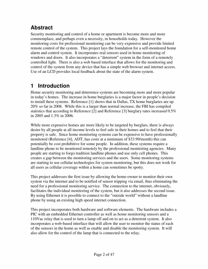
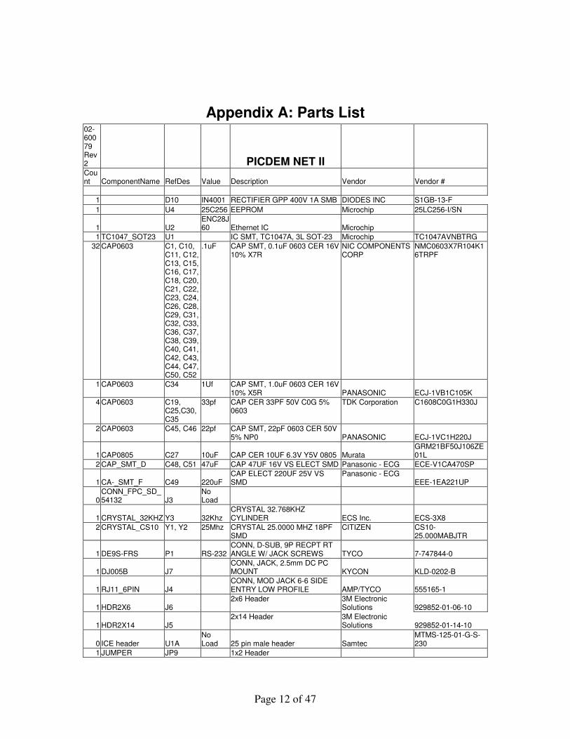
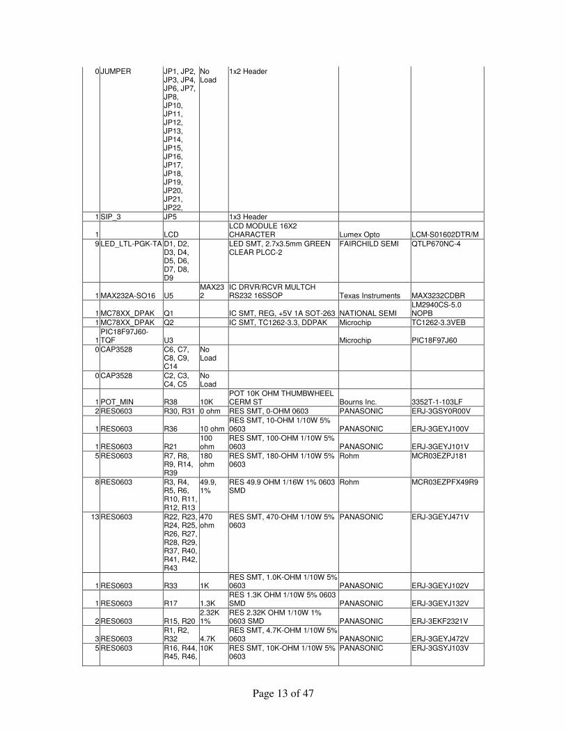
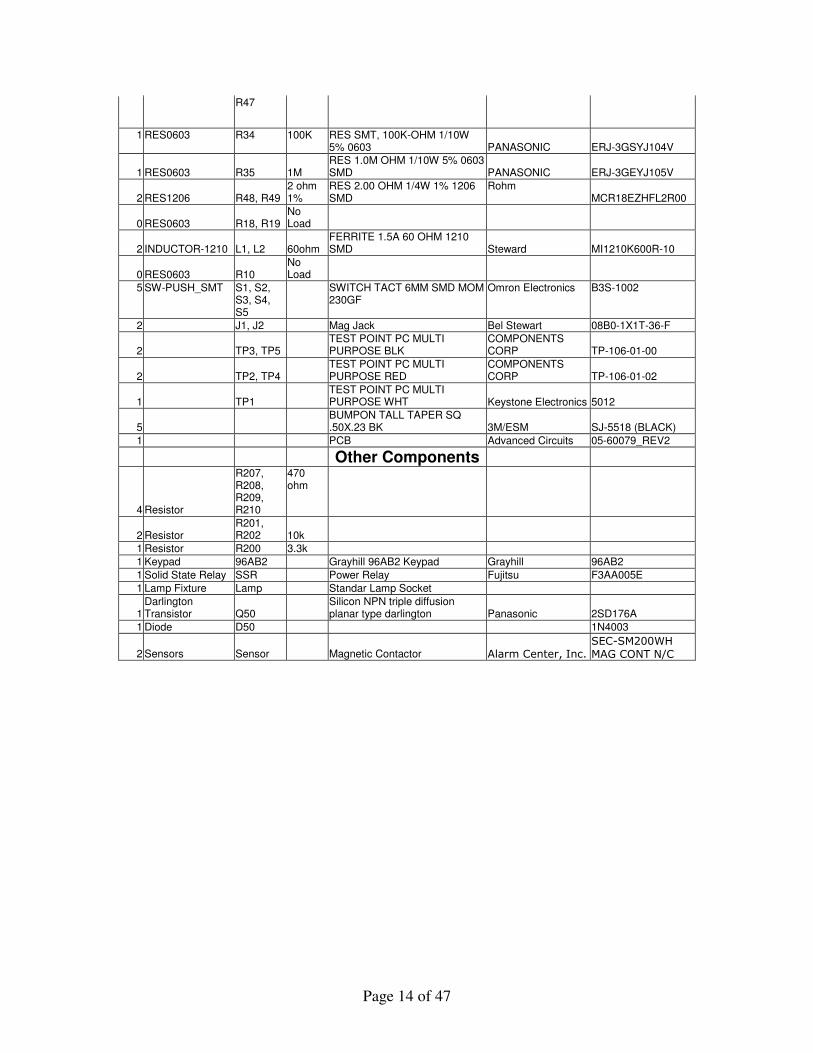
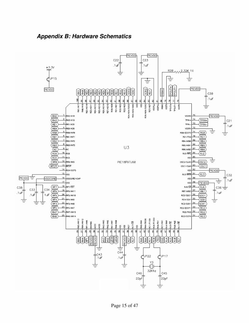
2 Hardware The home monitoring system consists of several different hardware components. They are explained in detail in the following subsections. Figure 1 is a high level block diagram of the hardware used in the system. A complete parts list can be found in Appendix A. A full schematic of the system can be found in Appendix B. Schematics of the PICDEM.net 2 Development Board can be found on the Microchip web site [5].
2.1 PICDEM.net 2 Development Board
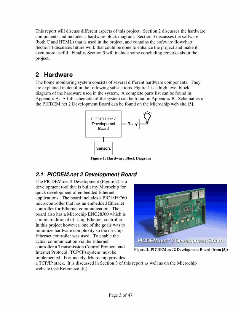
The PICDEM.net 2 Development (Figure 2) is a development tool that is built my Microchip for quick development of embedded Ethernet applications. The board includes a PIC18F9760 microcontroller that has an embedded Ethernet controller for Ethernet communication. The board also has a Microchip ENC28J60 which is a more traditional off-chip Ethernet controller. In this project however, one of the goals was to minimize hardware complexity so the on-chip Ethernet controller was used. To enable the actual communication via the Ethernet controller a Transmission Control Protocol and Internet Protocol (TCP/IP) system must be implemented. Fortunately, Microchip provides a TCP/IP stack. It is discussed in Section 3 of this report as well as on the Microchip website (see Reference [6]).
Figure 1: Hardware Block Diagram
Figure 2: PICDEM.net 2 Development Board (from [5])
Page 4 of 47
Also present on the development board are several other hardware components. Some of these are used in the project wile many others are not. The board has eight LED’s that are user controllable. LED 0 is used as a status LED and blinks off an on to indicate that the board software is indeed running. LED 7 is a mirror of the status of the relay that drives the lamp. When the lamp is on, so is LED7 and vice versa. This gives an indication in case the bulb on the lamp is burned out. The development board also contains a two-line sixteen character LCD. In this project the LCD is used to display system information that includes “System Disabled,” “Enabling System,” “Monitoring System,” and “Alarm.” These correspond to the different states the system can be. Each of the states are discussed in detail in Section 3.2.2.1. Some other smaller components on the board include a block header that is used to connect to the external sensors and relay, as well as a connector that used to connect directly to the Microchip ICD2 programmer and debugger. There is also an RJ45 port on the board used to connect an Ethernet cable to the Ethernet controller on the board.
2.2 Sensors
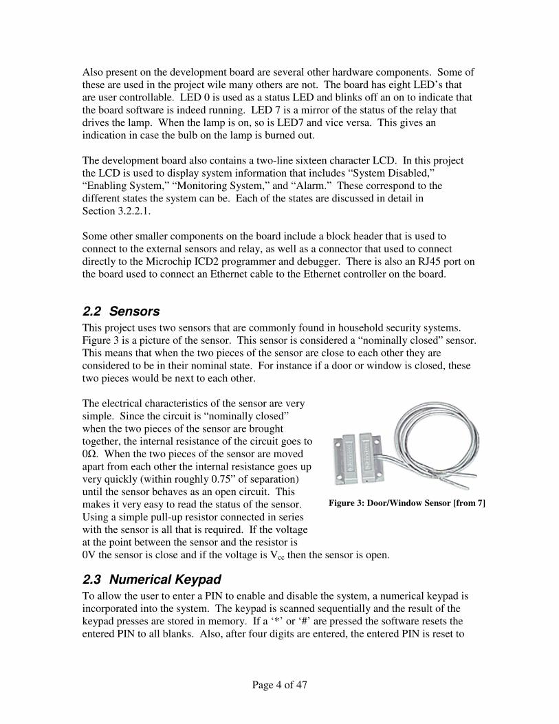
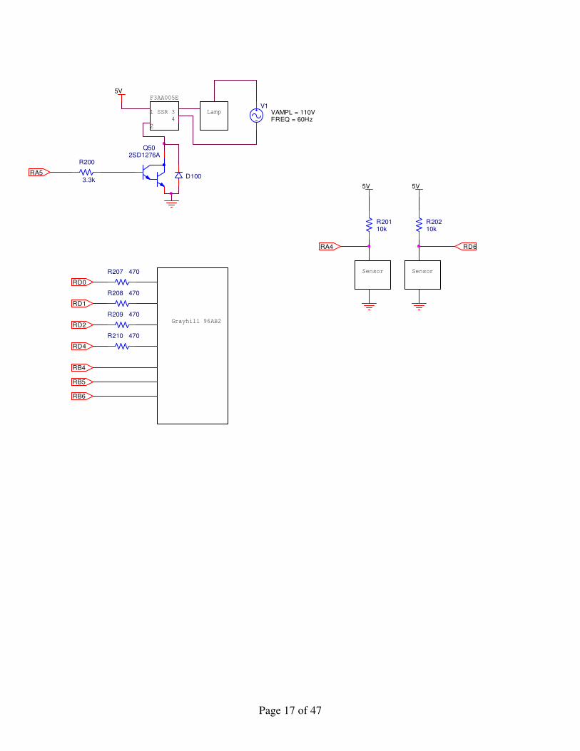
This project uses two sensors that are commonly found in household security systems. Figure 3 is a picture of the sensor. This sensor is considered a “nominally closed” sensor. This means that when the two pieces of the sensor are close to each other they are considered to be in their nominal state. For instance if a door or window is closed, these two pieces would be next to each other. The electrical characteristics of the sensor are very simple. Since the circuit is “nominally closed” when the two pieces of the sensor are brought together, the internal resistance of the circuit goes to 0Ω. When the two pieces of the sensor are moved apart from each other the internal resistance goes up very quickly (within roughly 0.75” of separation) until the sensor behaves as an open circuit. This makes it very easy to read the status of the sensor. Using a simple pull-up resistor connected in series with the sensor is all that is required. If the voltage at the point between the sensor and the resistor is 0V the sensor is close and if the voltage is Vcc then the sensor is open.
2.3 Numerical Keypad
To allow the user to enter a PIN to enable and disable the system, a numerical keypad is incorporated into the system. The keypad is scanned sequentially and the result of the keypad presses are stored in memory. If a ‘*’ or ‘#’ are pressed the software resets the entered PIN to all blanks. Also, after four digits are entered, the entered PIN is reset to
Figure 3: Door/Window Sensor [from 7]
Page 5 of 47
all blanks if the PIN entered was incorrect. There is no safeguard for a case when multiple keys are pressed at the same time.
2.4 Relay and Lamp
In order to help deter burglars, a fully controllable lamp is implemented. Using a simple relay controlled by an output pin on the PIC a lamp socket is hooked up to 110Vac. The bulb that is used is only 40W to avoid drawing too much current through the relay and burning it out. In future designs the lamp socket could be replaced by an electrical outlet to allow anything using standard 110Vac voltage to be plugged in, and a fuse could be added to avoid burning out the relay.
3 Software There are two main components to the software in the home monitoring system. HTML code (Section 3.1) is used to create the web-based user interface, and C code (Section 3.2) is used to program the PIC. A full listing of all of the files used can be found in Appendix C
3.1 HTML Source Code
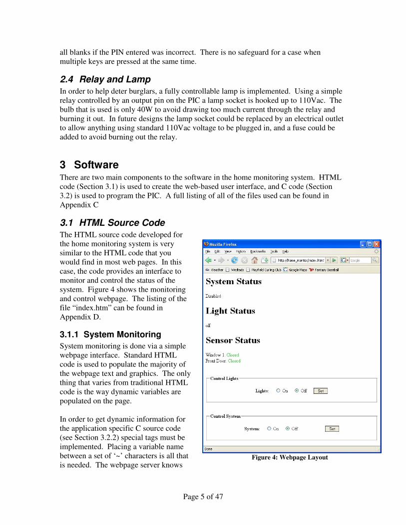
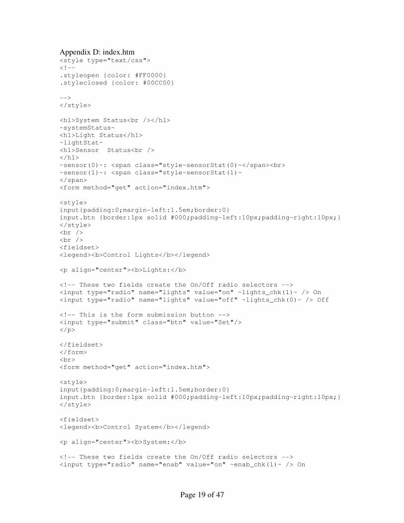
The HTML source code developed for the home monitoring system is very similar to the HTML code that you would find in most web pages. In this case, the code provides an interface to monitor and control the status of the system. Figure 4 shows the monitoring and control webpage. The listing of the file “index.htm” can be found in Appendix D.
3.1.1 System Monitoring
System monitoring is done via a simple webpage interface. Standard HTML code is used to populate the majority of the webpage text and graphics. The only thing that varies from traditional HTML code is the way dynamic variables are populated on the page. In order to get dynamic information for the application specific C source code (see Section 3.2.2) special tags must be implemented. Placing a variable name between a set of ‘~’ characters is all that is needed. The webpage server knows
Figure 4: Webpage Layout
Page 6 of 47
that when a variable is placed between these characters there must be callback function implemented in the application specific C code that corresponds to the variable. An example of this can be seen in index.htm in Appendix D.
3.1.2 System Control
Control of the system is done through an HTML form and specifically, the “GET” method of HTML forms. A “GET” method form passes arguments to the server in the URL requested from the server. For instance, a simple request for the index.html page would be “http://home_monitor/index.html”. Now let’s say that a request to turn a light on is sent from the web form. The requested webpage URL would look something like “http://home_monitor/index.html?lights=on”. The “lights=on” part of the code is passed from the webpage server to the application specific C code which then parses the arguments and takes the appropriate action (see Section 3.2.2). For those familiar with the “POST” method of HTML forms, this is also possible with the web forms on the PIC, however the method to parse the arguments is more complicated as the arguments are not passed as part of the URL. Since the POST method is not needed in the home monitoring system, it is not implemented.
3.1.3 MPFS2 Utility
Microchip provides a utility called MPFS2 that enables the loading of all of the HTML code onto the PIC/EEPROM. It takes a directory containing HTML files and converts it into a file system format that the PIC can use. In the case of this project, the MPFS2 image is created and uploaded to EEPROM on the PICDEM.net 2 development board. The TCP/IP Stack (see Section 3.2.1) can then access the web pages stored on the EEPROM and serve them.
3.2 C Source Code
To examine the code used and developed for the project, it is easiest to break it into two sections. This first is Microchip’s TCPIP stack (Section 3.2.1) that was mentioned above, and the second is the custom code developed specifically for the home monitoring system (Section 3.2.2). Both sections of code are placed in one Project in the MPLAB IDE and compiled together into one executable that is then loaded into the PIC program memory. In order to use the TCP/IP stack, the C programming language must be used. While programming in C can take up more space in memory, the PIC18F97J60 has more than adequate storage space for the program.
3.2.1 Microchip TCPIP Stack
TCP/IP is the standard that is used for communication across the internet. It is a relatively complex protocol that is very difficult to master. Microchip provides a TCP/IP stack software that eases the process of creating an “online” microcontroller by taking care of the majority of the web interface needs. All that needs to be developed is application specific code. That is discussed in Section 3.2.2.
Page 7 of 47
Several modules included in the TCP/IP stack are used. One particularly important one implements the Dynamic Host Configuration Protocol (DHCP). The DHCP module allows the board to be plugged in directly to a network and to have the board obtain a unique IP address. This is important in distinguishing the board from other devices on a network. More information about the Microchip TCP/IP stack can be found at Reference [6].
3.2.2 Application Specific Code
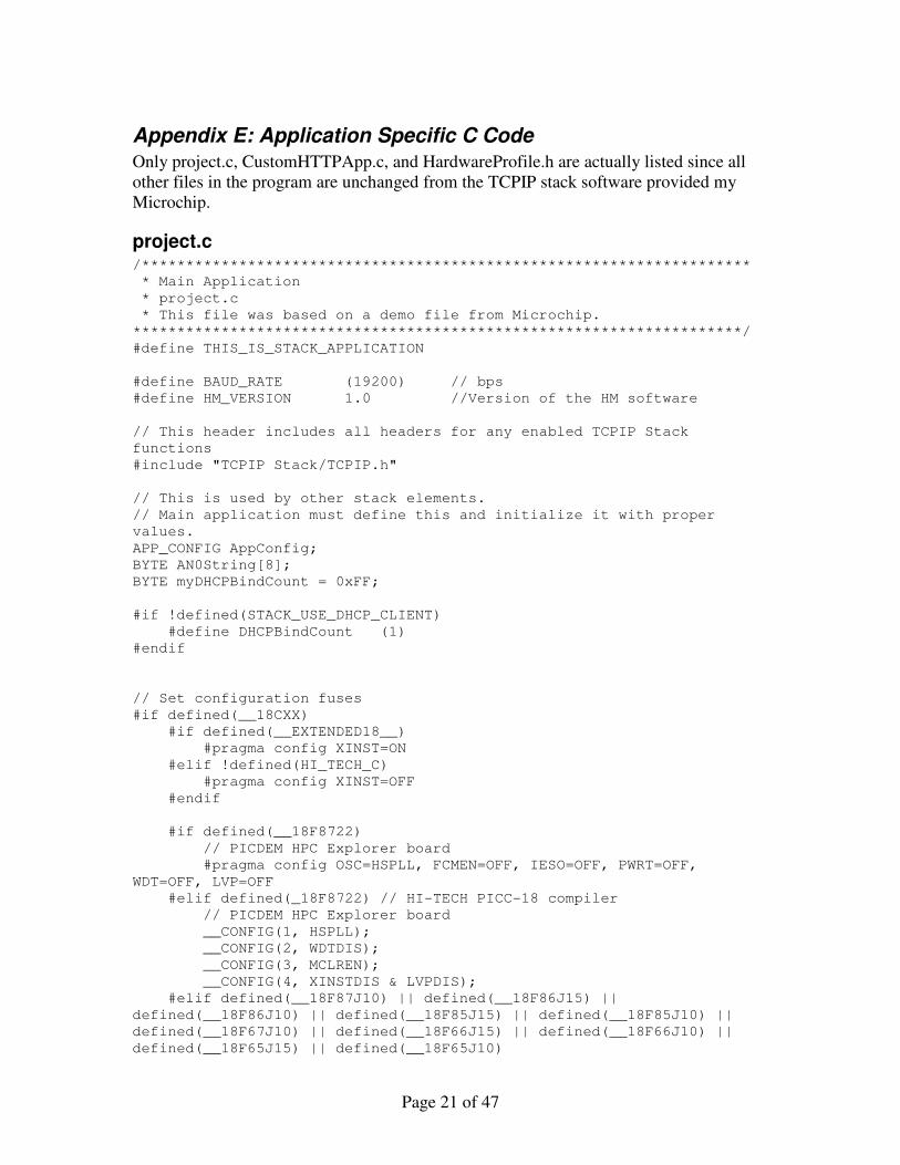
There are several different pieces to the application specific code written for the PIC. They are broken up below into sections on the system state machine, hardware input/output (I/O), and HTML call backs. The example code that Microchip provides was used as a starting point for the application specific code. The custom C files can be found in Appendix E.
3.2.2.1 State Machine
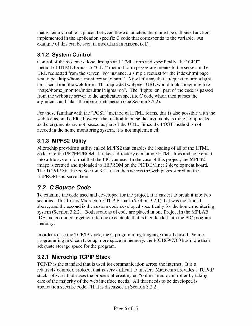
The home monitoring systems follows a very straight forward state machine model. Figure 5 shows the flow of the state machine from one state to the next. When the system is disabled, it simply loops in the “Idle” state waiting for the system to become enabled. Once enabled, the system goes into the “Delay” state. Here the system delays for one minute before fully enabling the alarm. This allows an owner to enable the system before leaving the home without tripping a sensor. After the one minute delay the system enters the “Monitor Sensors” state. In this state the system is simply scanning the sensors. If the PIN is entered on the keypad or via the webpage, the system goes back to the idle state. If a break in a sensor is detected, the system goes into the “Alarm’ state.
Figure 5: System State Machine
Page 8 of 47
In the “Alarm” state the system simply waits to see if the PIN is entered to disable the system. If within one minute the code is not entered, the system sends an email to a specified email address (the “Send Email” state). Once the email is sent the system remains in the “Alarm” state until the PIN is entered to disable the system.
3.2.2.2 Input/Output
The only true output of the hardware is the relay control that controls the lamp. The lamp is controlled by the HTML code and is a simple on/off control. There are two inputs to the system. The door and windows sensors are scanned by the software and their status is used to determine the next state of the state machine. The keypad is also polled continuously for inputs. By using a simple keypad scanning algorithm all inputs are captured. One interesting note here is that because the system is operating at such a high operating frequency it was necessary to add two things to the keypad scanning code. First, when negating a row to scan, it was found during testing that a nop had to be added after the negation to allow enough time for the line to drop to 0V. Secondly code was added to keep track of the previous button pushed. This is a way to make sure that the button was actually released and that the same button press isn’t being registered hundreds, or even thousands, of times.
3.2.2.3 HTML Callbacks
The HTML callbacks are the code that allows the webpage server to interact with the PIC. As mentioned in Section 3.1 the HTML code must be formatted correctly to enable these callbacks to work. Say for instance the webpage was requesting the variable “foo”. It would request this by bracketing the foo by ‘~’ characters (~foo~). In order to make sure the value of foo is returned a specific function must be added to CustomHTTPApp.C and compiled with the rest of the source code. The format of the function name is
HTTPPrint_varname()
In the above example the function to get foo would we HTTPPrint_foo()
This function would literally replace the ~foo~ in the HTML with the HTML text you want. In the case of the home monitoring system many of the variables are replaced with status information like “open” or “closed”. When a GET method is called from the HTML (clicking on the “set” button on the
webpage) another function is called (HTTPExecuteGet()).. This function parses the incoming data and takes the appropriate action. For the home monitoring system this function turns the light off and on as well as enables and disables the system provided the user entered the correct PIN on the webpage. All of these callback functions can be found in the CustonHTTPApp.C file in Appendix E.
Page 9 of 47
4 Future Work There are several things that could be added to the project to make it more robust in the future. Here is a list of a few of the possibilities:
• Webpage encryption to allow for secure communication over the internet
• Programmable number of sensors to allow for arbitrary expansion of the system with no code changes
• Programmable PIN/Multiple PINs
• Add an alarm buzzer using the PWM module and a speaker
• Move from bread board to custom designed package
• Change from a hardwired lamp to an electrical outlet to allow for any lamp to be plugged into the circuit.
• Add video/audio feeds from the system to the web
5 Conclusion As it stands right now it can be used to monitor two doors or windows in a house as well as control a light that can be used as a deterrent to potential intruders. It also laid a solid foundation for a larger and more robust system. The project made use of the PICDEM.net 2 development board from Microchip to greatly speed the development process of the system. However this was done with at the expense of higher hardware cost since the development board is fairly expensive. For future systems it would make sense to use a custom designed board to minimize production cost of even small quantities of the product. Overall the project was a great success and all to the goals outlined in the project proposal were achieved.
6 References [1] Dallas Burglary Rate Up By 20 Percent
http://www.nbc5i.com/newsarchive/15882965/detail.html
[2] Crime in the United States 2005 http://www.fbi.gov/ucr/05cius/offenses/property_crime/burglary.html
[3] Crime in the United States 2006 http://www.fbi.gov/ucr/cius2006/offenses/property_crime/burglary.html
[4] ADT Home Service http://www.adt.com/wps/portal/adt/for_your_home/products_services/security_systems/

Page 10 of 47
[5] PICDEM.net 2 Development Board http://www.microchip.com/stellent/idcplg?IdcService=SS_GET_PAGE&nodeId=1406&dDocName=en028217
[6] TCP/IP Solutions http://www.microchip.com/stellent/idcplg?IdcService=SS_GET_PAGE&nodeId=1489

Page 11 of 47
Appendices
Page 12 of 47
Appendix A: Parts List 02-60079 Rev 2 PICDEM NET II
Count ComponentName RefDes Value Description Vendor Vendor #
1 D10 IN4001 RECTIFIER GPP 400V 1A SMB DIODES INC S1GB-13-F
1 U4 25C256 EEPROM Microchip 25LC256-I/SN
1 U2 ENC28J60 Ethernet IC Microchip
1 TC1047_SOT23 U1 IC SMT, TC1047A, 3L SOT-23 Microchip TC1047AVNBTRG
32 CAP0603 C1, C10, C11, C12, C13, C15, C16, C17, C18, C20, C21, C22, C23, C24, C26, C28, C29, C31, C32, C33, C36, C37, C38, C39, C40, C41, C42, C43, C44, C47, C50, C52
.1uF CAP SMT, 0.1uF 0603 CER 16V 10% X7R
NIC COMPONENTS CORP
NMC0603X7R104K16TRPF
1 CAP0603 C34 1Uf CAP SMT, 1.0uF 0603 CER 16V 10% X5R PANASONIC ECJ-1VB1C105K
4 CAP0603 C19, C25,C30,C35
33pf CAP CER 33PF 50V C0G 5% 0603
TDK Corporation C1608C0G1H330J
2 CAP0603 C45, C46 22pf CAP SMT, 22pF 0603 CER 50V 5% NP0 PANASONIC ECJ-1VC1H220J
1 CAP0805 C27 10uF CAP CER 10UF 6.3V Y5V 0805 Murata GRM21BF50J106ZE01L
2 CAP_SMT_D C48, C51 47uF CAP 47UF 16V VS ELECT SMD Panasonic - ECG ECE-V1CA470SP
1 CA-_SMT_F C49 220uF CAP ELECT 220UF 25V VS SMD
Panasonic - ECG EEE-1EA221UP
0 CONN_FPC_SD_54132 J3
No Load
1 CRYSTAL_32KHZ Y3 32Khz CRYSTAL 32.768KHZ CYLINDER ECS Inc. ECS-3X8
2 CRYSTAL_CS10 Y1, Y2 25Mhz CRYSTAL 25.0000 MHZ 18PF SMD
CITIZEN CS10-25.000MABJTR
1 DE9S-FRS P1 RS-232 CONN, D-SUB, 9P RECPT RT ANGLE W/ JACK SCREWS TYCO 7-747844-0
1 DJ005B J7 CONN, JACK, 2.5mm DC PC MOUNT KYCON KLD-0202-B
1 RJ11_6PIN J4 CONN, MOD JACK 6-6 SIDE ENTRY LOW PROFILE AMP/TYCO 555165-1
1 HDR2X6 J6 2x6 Header 3M Electronic
Solutions 929852-01-06-10
1 HDR2X14 J5 2x14 Header 3M Electronic
Solutions 929852-01-14-10
0 ICE header U1A No Load 25 pin male header Samtec
MTMS-125-01-G-S-230
1 JUMPER JP9 1x2 Header
Page 13 of 47
0 JUMPER JP1, JP2, JP3, JP4, JP6, JP7, JP8, JP10, JP11, JP12, JP13, JP14, JP15, JP16, JP17, JP18, JP19, JP20, JP21, JP22,
No Load
1x2 Header
1 SIP_3 JP5 1x3 Header
1 LCD LCD MODULE 16X2 CHARACTER Lumex Opto LCM-S01602DTR/M
9 LED_LTL-PGK-TA D1, D2, D3, D4, D5, D6, D7, D8, D9
LED SMT, 2.7x3.5mm GREEN CLEAR PLCC-2
FAIRCHILD SEMI QTLP670NC-4
1 MAX232A-SO16 U5 MAX232
IC DRVR/RCVR MULTCH RS232 16SSOP Texas Instruments MAX3232CDBR
1 MC78XX_DPAK Q1 IC SMT, REG, +5V 1A SOT-263 NATIONAL SEMI LM2940CS-5.0 NOPB
1 MC78XX_DPAK Q2 IC SMT, TC1262-3.3, DDPAK Microchip TC1262-3.3VEB
1 PIC18F97J60-TQF U3 Microchip PIC18F97J60
0 CAP3528 C6, C7, C8, C9, C14
No Load
0 CAP3528 C2, C3, C4, C5
No Load
1 POT_MIN R38 10K POT 10K OHM THUMBWHEEL CERM ST Bourns Inc. 3352T-1-103LF
2 RES0603 R30, R31 0 ohm RES SMT, 0-OHM 0603 PANASONIC ERJ-3GSY0R00V
1 RES0603 R36 10 ohm RES SMT, 10-OHM 1/10W 5% 0603 PANASONIC ERJ-3GEYJ100V
1 RES0603 R21 100 ohm
RES SMT, 100-OHM 1/10W 5% 0603 PANASONIC ERJ-3GEYJ101V
5 RES0603 R7, R8, R9, R14, R39
180 ohm
RES SMT, 180-OHM 1/10W 5% 0603
Rohm MCR03EZPJ181
8 RES0603 R3, R4, R5, R6, R10, R11, R12, R13
49.9, 1%
RES 49.9 OHM 1/16W 1% 0603 SMD
Rohm MCR03EZPFX49R9
13 RES0603 R22, R23, R24, R25, R26, R27, R28, R29, R37, R40, R41, R42, R43
470 ohm
RES SMT, 470-OHM 1/10W 5% 0603
PANASONIC ERJ-3GEYJ471V
1 RES0603 R33 1K RES SMT, 1.0K-OHM 1/10W 5% 0603 PANASONIC ERJ-3GEYJ102V
1 RES0603 R17 1.3K RES 1.3K OHM 1/10W 5% 0603 SMD PANASONIC ERJ-3GEYJ132V
2 RES0603 R15, R20 2.32K 1%
RES 2.32K OHM 1/10W 1% 0603 SMD PANASONIC ERJ-3EKF2321V
3 RES0603 R1, R2, R32 4.7K
RES SMT, 4.7K-OHM 1/10W 5% 0603 PANASONIC ERJ-3GEYJ472V
5 RES0603 R16, R44, R45, R46,
10K RES SMT, 10K-OHM 1/10W 5% 0603
PANASONIC ERJ-3GSYJ103V
Page 14 of 47
R47
1 RES0603 R34 100K RES SMT, 100K-OHM 1/10W 5% 0603 PANASONIC ERJ-3GSYJ104V
1 RES0603 R35 1M RES 1.0M OHM 1/10W 5% 0603 SMD PANASONIC ERJ-3GEYJ105V
2 RES1206 R48, R49 2 ohm 1%
RES 2.00 OHM 1/4W 1% 1206 SMD
Rohm MCR18EZHFL2R00
0 RES0603 R18, R19 No Load
2 INDUCTOR-1210 L1, L2 60ohm FERRITE 1.5A 60 OHM 1210 SMD Steward MI1210K600R-10
0 RES0603 R10 No Load
5 SW-PUSH_SMT S1, S2, S3, S4, S5
SWITCH TACT 6MM SMD MOM 230GF
Omron Electronics B3S-1002
2 J1, J2 Mag Jack Bel Stewart 08B0-1X1T-36-F
2 TP3, TP5 TEST POINT PC MULTI PURPOSE BLK
COMPONENTS CORP TP-106-01-00
2 TP2, TP4 TEST POINT PC MULTI PURPOSE RED
COMPONENTS CORP TP-106-01-02
1 TP1 TEST POINT PC MULTI PURPOSE WHT Keystone Electronics 5012
5 BUMPON TALL TAPER SQ .50X.23 BK 3M/ESM SJ-5518 (BLACK)
1 PCB Advanced Circuits 05-60079_REV2
Other Components
4 Resistor
R207, R208, R209, R210
470 ohm
2 Resistor R201, R202 10k
1 Resistor R200 3.3k
1 Keypad 96AB2 Grayhill 96AB2 Keypad Grayhill 96AB2
1 Solid State Relay SSR Power Relay Fujitsu F3AA005E
1 Lamp Fixture Lamp Standar Lamp Socket
1 Darlington Transistor Q50
Silicon NPN triple diffusion planar type darlington Panasonic 2SD176A
1 Diode D50 1N4003
2 Sensors Sensor Magnetic Contactor Alarm Center, Inc.
SEC-SM200WH
MAG CONT N/C
Page 15 of 47
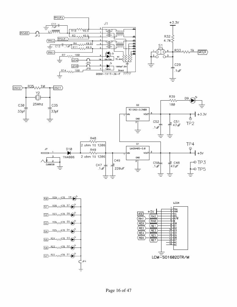
Appendix B: Hardware Schematics
Page 16 of 47
Page 17 of 47
RD2
R209 470
RD4
RB5
R207 470
R210 470
RD0
RB6
RB4
RD1
R208 470
Grayhill 96AB2
3
F3AA005E
V1
FREQ = 60HzVAMPL = 110V
Q502SD1276A
R200
3.3kD100
SSR
5V
Lamp1
2
4
RA5
Sensor
5V
Sensor
RA4
R20110k
RD6
R20210k
5V
Page 18 of 47
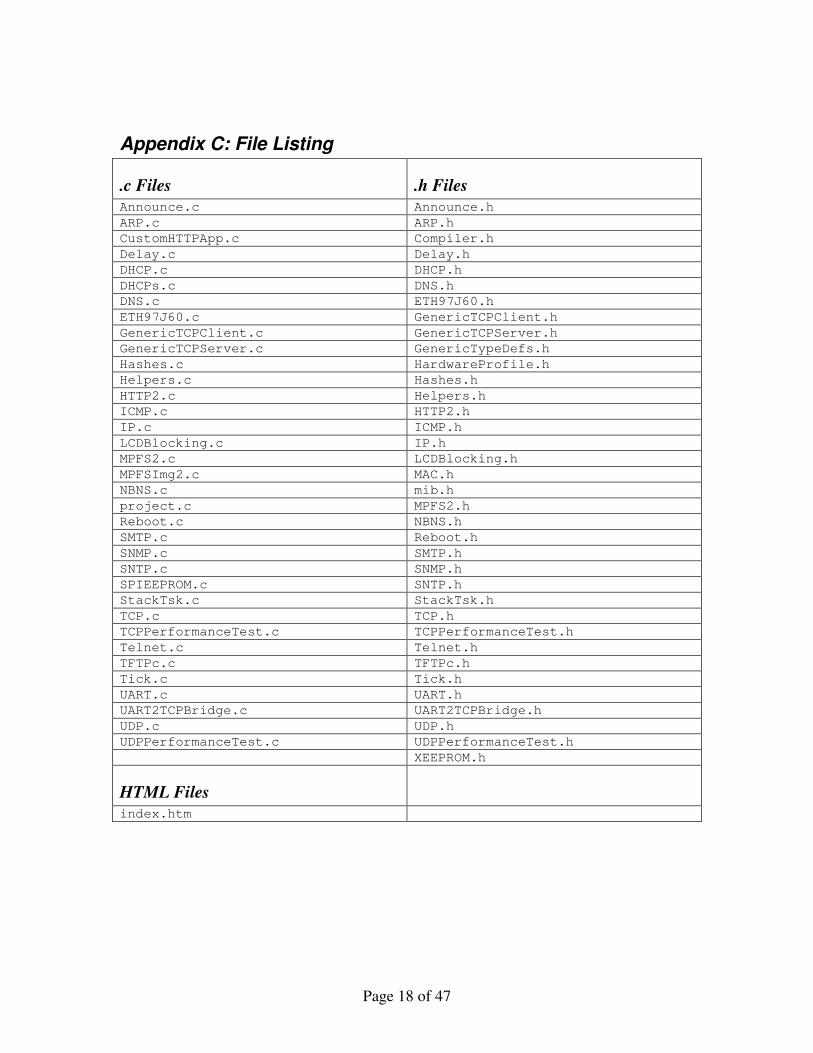
Appendix C: File Listing
.c Files .h Files
Announce.c Announce.h
ARP.c ARP.h
CustomHTTPApp.c Compiler.h
Delay.c Delay.h
DHCP.c DHCP.h
DHCPs.c DNS.h
DNS.c ETH97J60.h
ETH97J60.c GenericTCPClient.h
GenericTCPClient.c GenericTCPServer.h
GenericTCPServer.c GenericTypeDefs.h
Hashes.c HardwareProfile.h
Helpers.c Hashes.h
HTTP2.c Helpers.h
ICMP.c HTTP2.h
IP.c ICMP.h
LCDBlocking.c IP.h
MPFS2.c LCDBlocking.h
MPFSImg2.c MAC.h
NBNS.c mib.h
project.c MPFS2.h
Reboot.c NBNS.h
SMTP.c Reboot.h
SNMP.c SMTP.h
SNTP.c SNMP.h
SPIEEPROM.c SNTP.h
StackTsk.c StackTsk.h
TCP.c TCP.h
TCPPerformanceTest.c TCPPerformanceTest.h
Telnet.c Telnet.h
TFTPc.c TFTPc.h
Tick.c Tick.h
UART.c UART.h
UART2TCPBridge.c UART2TCPBridge.h
UDP.c UDP.h
UDPPerformanceTest.c UDPPerformanceTest.h
XEEPROM.h
HTML Files
index.htm
Page 19 of 47
Appendix D: index.htm
<style type="text/css">
<!--
.styleopen color: #FF0000
.styleclosed color: #00CC00
-->
</style>
<h1>System Status<br /></h1>
~systemStatus~
<h1>Light Status</h1>
~lightStat~
<h1>Sensor Status<br />
</h1>
~sensor(0)~: <span class="style~sensorStat(0)~</span><br>
~sensor(1)~: <span class="style~sensorStat(1)~
</span>
<form method="get" action="index.htm">
<style>
inputpadding:0;margin-left:1.5em;border:0
input.btn border:1px solid #000;padding-left:10px;padding-right:10px;
</style>
<br />
<br />
<fieldset>
<legend><b>Control Lights</b></legend>
<p align="center"><b>Lights:</b>
<!-- These two fields create the On/Off radio selectors -->
<input type="radio" name="lights" value="on" ~lights_chk(1)~ /> On
<input type="radio" name="lights" value="off" ~lights_chk(0)~ /> Off
<!-- This is the form submission button -->
<input type="submit" class="btn" value="Set"/>
</p>
</fieldset>
</form>
<br>
<form method="get" action="index.htm">
<style>
inputpadding:0;margin-left:1.5em;border:0
input.btn border:1px solid #000;padding-left:10px;padding-right:10px;
</style>
<fieldset>
<legend><b>Control System</b></legend>
<p align="center"><b>System:</b>
<!-- These two fields create the On/Off radio selectors -->
<input type="radio" name="enab" value="on" ~enab_chk(1)~ /> On
Page 20 of 47
<input type="radio" name="enab" value="off" ~enab_chk(0)~ /> Off
<input type="text" name="WebPIN" size="4">
<!-- This is the form submission button -->
<input type="submit" class="btn" value="Set"/>
</p>
</fieldset>
</form>
Page 21 of 47
Appendix E: Application Specific C Code
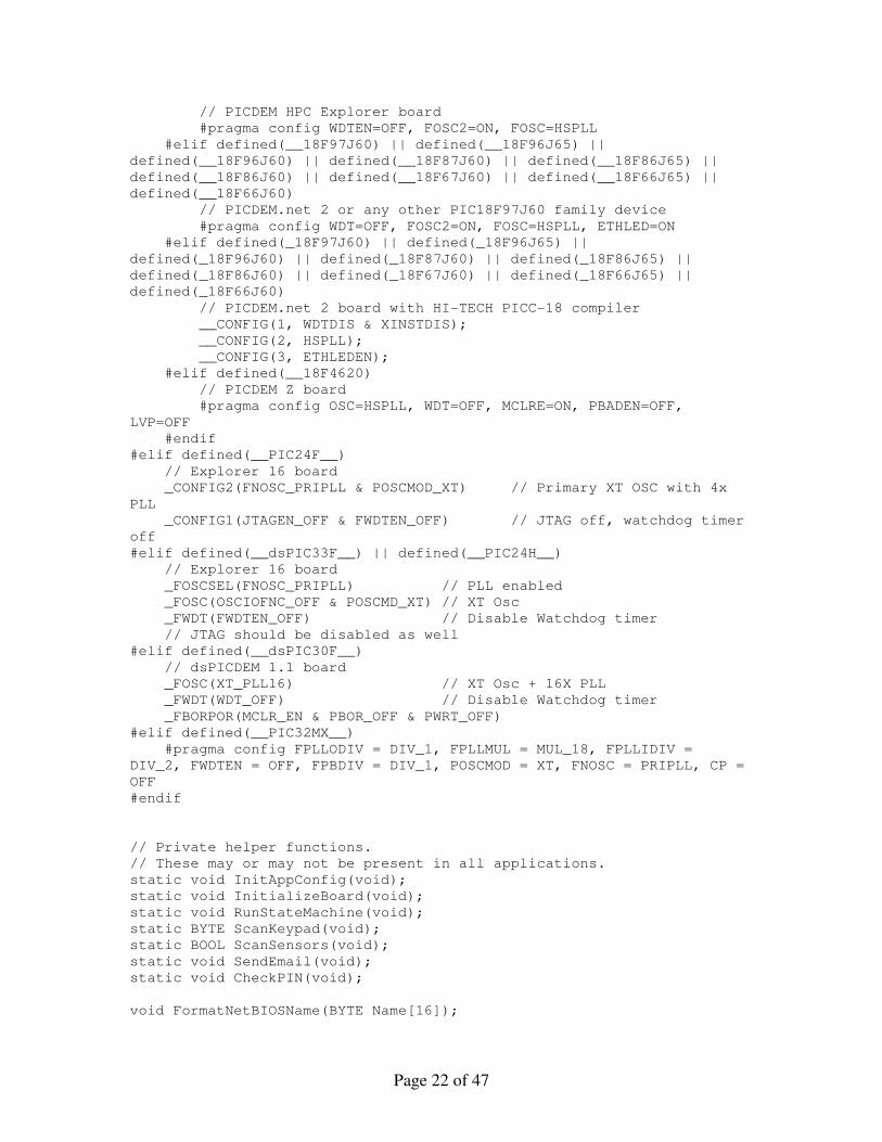
Only project.c, CustomHTTPApp.c, and HardwareProfile.h are actually listed since all other files in the program are unchanged from the TCPIP stack software provided my Microchip.
project.c /*********************************************************************
* Main Application
* project.c
* This file was based on a demo file from Microchip.
*********************************************************************/
#define THIS_IS_STACK_APPLICATION
#define BAUD_RATE (19200) // bps
#define HM_VERSION 1.0 //Version of the HM software
// This header includes all headers for any enabled TCPIP Stack
functions
#include "TCPIP Stack/TCPIP.h"
// This is used by other stack elements.
// Main application must define this and initialize it with proper
values.
APP_CONFIG AppConfig;
BYTE AN0String[8];
BYTE myDHCPBindCount = 0xFF;
#if !defined(STACK_USE_DHCP_CLIENT)
#define DHCPBindCount (1)
#endif
// Set configuration fuses
#if defined(__18CXX)
#if defined(__EXTENDED18__)
#pragma config XINST=ON
#elif !defined(HI_TECH_C)
#pragma config XINST=OFF
#endif
#if defined(__18F8722)
// PICDEM HPC Explorer board
#pragma config OSC=HSPLL, FCMEN=OFF, IESO=OFF, PWRT=OFF,
WDT=OFF, LVP=OFF
#elif defined(_18F8722) // HI-TECH PICC-18 compiler
// PICDEM HPC Explorer board
__CONFIG(1, HSPLL);
__CONFIG(2, WDTDIS);
__CONFIG(3, MCLREN);
__CONFIG(4, XINSTDIS & LVPDIS);
#elif defined(__18F87J10) || defined(__18F86J15) ||
defined(__18F86J10) || defined(__18F85J15) || defined(__18F85J10) ||
defined(__18F67J10) || defined(__18F66J15) || defined(__18F66J10) ||
defined(__18F65J15) || defined(__18F65J10)
Page 22 of 47
// PICDEM HPC Explorer board
#pragma config WDTEN=OFF, FOSC2=ON, FOSC=HSPLL
#elif defined(__18F97J60) || defined(__18F96J65) ||
defined(__18F96J60) || defined(__18F87J60) || defined(__18F86J65) ||
defined(__18F86J60) || defined(__18F67J60) || defined(__18F66J65) ||
defined(__18F66J60)
// PICDEM.net 2 or any other PIC18F97J60 family device
#pragma config WDT=OFF, FOSC2=ON, FOSC=HSPLL, ETHLED=ON
#elif defined(_18F97J60) || defined(_18F96J65) ||
defined(_18F96J60) || defined(_18F87J60) || defined(_18F86J65) ||
defined(_18F86J60) || defined(_18F67J60) || defined(_18F66J65) ||
defined(_18F66J60)
// PICDEM.net 2 board with HI-TECH PICC-18 compiler
__CONFIG(1, WDTDIS & XINSTDIS);
__CONFIG(2, HSPLL);
__CONFIG(3, ETHLEDEN);
#elif defined(__18F4620)
// PICDEM Z board
#pragma config OSC=HSPLL, WDT=OFF, MCLRE=ON, PBADEN=OFF,
LVP=OFF
#endif
#elif defined(__PIC24F__)
// Explorer 16 board
_CONFIG2(FNOSC_PRIPLL & POSCMOD_XT) // Primary XT OSC with 4x
PLL
_CONFIG1(JTAGEN_OFF & FWDTEN_OFF) // JTAG off, watchdog timer
off
#elif defined(__dsPIC33F__) || defined(__PIC24H__)
// Explorer 16 board
_FOSCSEL(FNOSC_PRIPLL) // PLL enabled
_FOSC(OSCIOFNC_OFF & POSCMD_XT) // XT Osc
_FWDT(FWDTEN_OFF) // Disable Watchdog timer
// JTAG should be disabled as well
#elif defined(__dsPIC30F__)
// dsPICDEM 1.1 board
_FOSC(XT_PLL16) // XT Osc + 16X PLL
_FWDT(WDT_OFF) // Disable Watchdog timer
_FBORPOR(MCLR_EN & PBOR_OFF & PWRT_OFF)
#elif defined(__PIC32MX__)
#pragma config FPLLODIV = DIV_1, FPLLMUL = MUL_18, FPLLIDIV =
DIV_2, FWDTEN = OFF, FPBDIV = DIV_1, POSCMOD = XT, FNOSC = PRIPLL, CP =
OFF
#endif
// Private helper functions.
// These may or may not be present in all applications.
static void InitAppConfig(void);
static void InitializeBoard(void);
static void RunStateMachine(void);
static BYTE ScanKeypad(void);
static BOOL ScanSensors(void);
static void SendEmail(void);
static void CheckPIN(void);
void FormatNetBIOSName(BYTE Name[16]);
Page 23 of 47
#if defined(MPFS_USE_EEPROM) && (defined(STACK_USE_MPFS) ||
defined(STACK_USE_MPFS2))
void SaveAppConfig(void);
#if defined(STACK_USE_UART) && defined(STACK_USE_MPFS)
static BOOL DownloadMPFS(void);
#endif
#else
#define SaveAppConfig()
#endif
//Home Monitoring Global Variables
BOOL LightOn; // Current Status of light
BYTE EnteredPIN[4]; // PIN entered via the keypad
BOOL Enab; // Is the sytem enabled or disabled
TICK AlarmTime; // Time the alarm is fired
BOOL EmailSent; // have we sent the email after the alarm?
BYTE PinPosition; // What byte in the pin are we entering
BYTE PIN[4]; // The PIN to enable and disable the system
char* sensorNames[2]; // Names of the sensors
BYTE sensorStatus[2]; // Status of the sensors true is closed
TICK delayTick; //Temp variable used to for delaying the
enamble
BYTE prevButton; //Previous keypad button pressed
static enum
SM_IDLE,
SM_ENABLE_DELAY,
SM_SCAN,
SM_ALARM_ON,
SM_SEND_EMAIL
sm = SM_IDLE; // Application state machine
static enum
MAIL_BEGIN = 0,
MAIL_SMTP_FINISHING
MailState = MAIL_BEGIN;
//
// PIC18 Interrupt Service Routines
//
// NOTE: Several PICs, including the PIC18F4620 revision A3 have a
RETFIE FAST/MOVFF bug
// The interruptlow keyword is used to work around the bug when using
C18
#if defined(__18CXX)
#if defined(HI_TECH_C)
void interrupt low_priority LowISR(void)
#else
#pragma interruptlow LowISR
void LowISR(void)
#endif
Page 24 of 47
TickUpdate();
#if defined(HI_TECH_C)
void interrupt HighISR(void)
#else
#pragma interruptlow HighISR
void HighISR(void)
#endif
#if defined(STACK_USE_UART2TCP_BRIDGE)
UART2TCPBridgeISR();
#endif
#if !defined(HI_TECH_C)
#pragma code lowVector=0x18
void LowVector(void)_asm goto LowISR _endasm
#pragma code highVector=0x8
void HighVector(void)_asm goto HighISR _endasm
#pragma code // Return to default code section
#endif
#endif
//
// Main application entry point.
//
void main(void)
static TICK t = 0;
BYTE i;
// Initialize any application specific hardware.
InitializeBoard();
#ifdef USE_LCD
// Initialize and display the stack version on the LCD
LCDInit();
for(i = 0; i < 100; i++)
DelayMs(1);
strcpypgm2ram((char*)LCDText, " Home Monitor "
" EEC517 SP08 ");
LCDUpdate();
#endif
// Initialize all stack related components.
// Following steps must be performed for all applications using
// the Microchip TCP/IP Stack.
TickInit();
#if defined(STACK_USE_MPFS) || defined(STACK_USE_MPFS2)
// Initialize Microchip File System module
MPFSInit();
#endif
Page 25 of 47
// Initialize Stack and application related NV variables into
AppConfig.
InitAppConfig();
// Initiates board setup process if button is depressed
// on startup
if(BUTTON0_IO == 0u)
#if defined(MPFS_USE_EEPROM) && (defined(STACK_USE_MPFS) ||
defined(STACK_USE_MPFS2))
// Invalidate the EEPROM contents if BUTTON0 is held down for
more than 4 seconds
TICK StartTime = TickGet();
while(BUTTON0_IO == 0u)
if(TickGet() - StartTime > 4*TICK_SECOND)
XEEBeginWrite(0x0000);
XEEWrite(0xFF);
XEEEndWrite();
#if defined(STACK_USE_UART)
putrsUART("\r\n\r\nBUTTON0 held for more than 4
seconds. EEPROM contents erased.\r\n\r\n");
#endif
LED0_TRIS = 0;
LED1_TRIS = 0;
LED2_TRIS = 0;
LED3_TRIS = 0;
LED0_IO = 1;
LED1_IO = 1;
LED2_IO = 1;
LED3_IO = 1;
while((LONG)(TickGet() - StartTime) <=
(LONG)(9*TICK_SECOND/2));
Reset();
break;
#endif
// Initialize core stack layers (MAC, ARP, TCP, UDP)
StackInit();
#if defined(STACK_USE_UART2TCP_BRIDGE)
UART2TCPBridgeInit();
#endif
#if defined(STACK_USE_HTTP_SERVER) || defined(STACK_USE_HTTP2_SERVER)
HTTPInit();
#endif
#if defined(STACK_USE_SSL_SERVER)
SSLInit();
#endif
Page 26 of 47
#if defined(STACK_USE_FTP_SERVER) && defined(MPFS_USE_EEPROM) &&
defined(STACK_USE_MPFS)
FTPInit();
#endif
#if defined(STACK_USE_SNMP_SERVER)
SNMPInit();
#endif
#if defined(STACK_USE_DHCP_CLIENT)
if(!AppConfig.Flags.bIsDHCPEnabled)
DHCPDisable();
#endif
// Once all items are initialized, go into infinite loop and let
// stack items execute their tasks.
// If application needs to perform its own task, it should be
// done at the end of while loop.
// Note that this is a "co-operative mult-tasking" mechanism
// where every task performs its tasks (whether all in one shot
// or part of it) and returns so that other tasks can do their
// job.
// If a task needs very long time to do its job, it must be broken
// down into smaller pieces so that other tasks can have CPU time.
while(1)
// Blink LED0 (right most one) every second.
if(TickGet() - t >= TICK_SECOND/2ul)
t = TickGet();
LED0_IO ^= 1;
// This task performs normal stack task including checking
// for incoming packet, type of packet and calling
// appropriate stack entity to process it.
StackTask();
#if defined(STACK_USE_UART2TCP_BRIDGE)
UART2TCPBridgeTask();
#endif
#if defined(STACK_USE_HTTP_SERVER) || defined(STACK_USE_HTTP2_SERVER)
// This is a TCP application. It listens to TCP port 80
// with one or more sockets and responds to remote requests.
HTTPServer();
#endif
#if defined(STACK_USE_SSL_SERVER)
SSLServer();
#endif
#if defined(STACK_USE_FTP_SERVER) && defined(MPFS_USE_EEPROM) &&
defined(STACK_USE_MPFS)
Page 27 of 47
FTPServer();
#endif
#if defined(STACK_USE_SNMP_SERVER)
SNMPTask();
#endif
#if defined(STACK_USE_ANNOUNCE)
DiscoveryTask();
#endif
#if defined(STACK_USE_NBNS)
NBNSTask();
#endif
#if defined(STACK_USE_DHCP_SERVER)
DHCPServerTask();
#endif
#if defined(STACK_USE_GENERIC_TCP_CLIENT_EXAMPLE)
GenericTCPClient();
#endif
#if defined(STACK_USE_GENERIC_TCP_SERVER_EXAMPLE)
GenericTCPServer();
#endif
#if defined(STACK_USE_TELNET_SERVER)
TelnetTask();
#endif
#if defined(STACK_USE_REBOOT_SERVER)
RebootTask();
#endif
#if defined(STACK_USE_SNTP_CLIENT)
SNTPClient();
#endif
#if defined(STACK_USE_UDP_PERFORMANCE_TEST)
UDPPerformanceTask();
#endif
#if defined(STACK_USE_TCP_PERFORMANCE_TEST)
TCPPerformanceTask();
#endif
#if defined(STACK_USE_ICMP_CLIENT)
PingDemo();
#endif
#if defined(STACK_USE_SNMP_SERVER) && !defined(SNMP_TRAP_DISABLED)
SNMPTrapDemo();
#endif
RunStateMachine();
Page 28 of 47
ScanSensors();
CheckPIN();
PORTJbits.RJ7 = LightOn;
PORTAbits.RA5 = LightOn;
/**********************************************************************
**
* This function runs and tracks the current state of the program.
* The different states are all enumerated above.
***********************************************************************
*/
static void RunStateMachine(void)
int i;
//Run the sate machine
switch(sm)
case SM_IDLE:
if(ScanSensors() == FALSE)
Enab = FALSE;
if(Enab == TRUE)
sm = SM_ENABLE_DELAY;
delayTick = TickGet();
strcpypgm2ram((char*)LCDText, "System Disabled "
" ");
LCDUpdate();
break;
case SM_ENABLE_DELAY:
strcpypgm2ram((char*)LCDText, " Enabling Alarm "
" ");
LCDUpdate();
if(TickGet() - delayTick > 60*TICK_SECOND)
sm = SM_SCAN;
break;
case SM_SCAN://Scan Sensors
EmailSent = FALSE;
if(ScanSensors() == FALSE)//Sensor was opened
sm = SM_ALARM_ON;
AlarmTime = TickGet();
break;
if(Enab == FALSE)//System has been disabled
sm = SM_IDLE;
strcpypgm2ram((char*)LCDText, " System Enabled "
" ");
LCDUpdate();
break;
case SM_ALARM_ON://Alarm is on
strcpypgm2ram((char*)LCDText, " ALARM!!!!!!! "
" ALARM!!!!!!! ");
Page 29 of 47
LCDUpdate();
if(TickGet() - AlarmTime > 60*TICK_SECOND && EmailSent !=
TRUE)
sm = SM_SEND_EMAIL;
LightOn = TRUE;
if(Enab == FALSE)//System has been disabled
sm = SM_IDLE;
break;
case SM_SEND_EMAIL:
SendEmail();
SendEmail(); //Call a second time to make sure email is
sent
EmailSent = TRUE;
sm = SM_ALARM_ON;
break;
/**********************************************************************
***
* This function calls the scanning of the keypad and checks to see if
the PIN
* that has been entered, matches the PIN in the program. The one thing
to note
* in this function is that the previous button pressed is stored. This
is used
* to compare against the new value received to assure that we don't get
* a ton of the same number when the user only pressed the button once.
***********************************************************************
***/
static void CheckPIN(void)
BYTE button;
BYTE i;
button = ScanKeypad();
//Was the button press still the same as last time?
if(prevButton == button)
return;
else
prevButton = button;
//No key pressed
if(button == 12)
return;
// # or * was pressed so reset the PIN Postion
if(button == 10 || button == 11)
PinPosition = 0;
return;
Page 30 of 47
//Enter the pin and check if the pin matches the memory.
//If there has been 4 digits entered and it doesn't match,
//then reset the PIN Entered
//If less than 4 digits have been entered than just return
//DelayMs(500);//Delay to avoid multiple button presses
EnteredPIN[PinPosition] = button;
PinPosition++;
if(PinPosition == 4)
//Check for match and if not matched reset the PIN Entered and
return
for(i=0; i<4; i++)
if(EnteredPIN[i] != PIN[i])
PinPosition = 0;
return;
//PIN Matched
//if(ScanSensors() == TRUE && Enab == FALSE || Enab == TRUE)
Enab ^= 1;
//
PinPosition = 0;
return;
else
return;
/*********************************************
* this function scans the keypad and proccesses all the inputs.
* If the system is enabled, entering a valid PIN will disable it
* unless the system has been in alarm mode for more than 1 minute.
* If the system is disabled, entering the PIN will enable it
* If a * or # is pressed the PIN will reset
* The pin will also reset if an invalid PIN is entered
**********************************************/
static BYTE ScanKeypad(void)
//Need to reset the outputs high in case we returned
//early before
KP_ROW2 = 1;
KP_ROW3 = 1;
KP_ROW4 = 1;
//Scan Keypad
KP_ROW1 = 0;
Nop();//Allow time for the pin to drop to Ground
if(KP_COL1 == 0) return 1;
if(KP_COL2 == 0) return 2;
if(KP_COL3 == 0) return 3;
KP_ROW1 = 1;
KP_ROW2 = 0;
Nop();//Allow time for the pin to drop to Ground
if(KP_COL1 == 0) return 4;
if(KP_COL2 == 0) return 5;
if(KP_COL3 == 0) return 6;
KP_ROW2 = 1;
Page 31 of 47
KP_ROW3 = 0;
Nop();//Allow time for the pin to drop to Ground
if(KP_COL1 == 0) return 7;
if(KP_COL2 == 0) return 8;
if(KP_COL3 == 0) return 9;
KP_ROW3 = 1;
KP_ROW4 = 0;
Nop();//Allow time for the pin to drop to Ground
if(KP_COL1 == 0) return 10; //a * was depressed
if(KP_COL2 == 0) return 0;
if(KP_COL3 == 0) return 11; //a # was depressed
KP_ROW4 = 1;
return 12;//default case when no key was pressed
//Return true is a sensor is detected to be open.
// Returns FALSE if a sensor is sensor is OPEN
static BOOL ScanSensors(void)
BYTE i;
sensorStatus[0] = PORTDbits.RD6;
sensorStatus[1] = PORTAbits.RA4;
for(i=0; i<2; i++)
if(sensorStatus[i] == 1)
return FALSE;
return TRUE;
/**********************************************************************
***
* This function sends out an email to a specified email address to
alert
* them that there has been a break in the system.
***********************************************************************
**/
static void SendEmail(void)
switch(MailState)
case MAIL_BEGIN:
if(SMTPBeginUsage())
// Note that these strings must stay allocated in
// memory until SMTPIsBusy() returns FALSE. To
// guarantee that the C compiler does not reuse this
// memory, you must allocate the strings as static.
static BYTE RAMStringTo[] = "[email protected]";
//static BYTE RAMStringCC[] = "[email protected],
\"Jane Smith\" <[email protected]>";
//static BYTE RAMStringBCC[] = "";
static BYTE RAMStringBody[] = "There has been a break
in your home montioring system!!!";
Page 32 of 47
SMTPClient.Server.szROM = (ROM
BYTE*)"mail.charter.net"; // SMTP server address
SMTPClient.ROMPointers.Server = 1;
//SMTPClient.Username.szROM = (ROM BYTE*)"mchpboard";
//SMTPClient.ROMPointers.Username = 1;
//SMTPClient.Password.szROM = (ROM
BYTE*)"secretpassword";
//SMTPClient.ROMPointers.Password = 1;
SMTPClient.To.szRAM = RAMStringTo;
SMTPClient.From.szROM = (ROM BYTE*)"\"SMTP Service\"
SMTPClient.ROMPointers.From = 1;
SMTPClient.Subject.szROM = (ROM BYTE*)"Break In!!";
SMTPClient.ROMPointers.Subject = 1;
SMTPClient.Body.szRAM = RAMStringBody;
SMTPSendMail();
MailState++;
break;
case MAIL_SMTP_FINISHING:
if(!SMTPIsBusy())
// Finished sending mail
MailState = 0;
break;
/*********************************************************************
* Function: void InitializeBoard(void)
*
* PreCondition: None
*
* Input: None
*
* Output: None
*
* Side Effects: None
*
* Overview: Initialize board specific hardware.
*
* Note: None
********************************************************************/
static void InitializeBoard(void)
// LEDs (note that these variables are defined in
HardwareProfile.h)
LED0_TRIS = 0;
LED1_TRIS = 0;
LED2_TRIS = 0;
LED3_TRIS = 0;
LED4_TRIS = 0;
LED5_TRIS = 0;
Page 33 of 47
LED6_TRIS = 0;
LED7_TRIS = 0;
LED0_IO = 0;
LED1_IO = 0;
LED2_IO = 0;
LED3_IO = 0;
LED4_IO = 0;
LED5_IO = 0;
LED6_IO = 0;
LED7_IO = 0;
//Output to control Relay for Light
TRISJbits.TRISJ7 = 0;
PORTJbits.RJ7 = 0;
TRISAbits.TRISA5 = 0;
PORTAbits.RA5 = 0;
//Inputs to read status of sensors
TRISDbits.TRISD6 = 1;
TRISAbits.TRISA4 = 1;
//Inputs to read keypad entries
TRISDbits.TRISD0 = 0; //row 1
TRISDbits.TRISD1 = 0; //row 2
TRISDbits.TRISD2 = 0; //row 3
TRISDbits.TRISD4 = 0; //row 4
TRISBbits.TRISB4 = 1; //column 1
TRISBbits.TRISB5 = 1; //column 2
TRISBbits.TRISB6 = 1; //column 3
KP_ROW1 = 1;
KP_ROW2 = 1;
KP_ROW3 = 1;
KP_ROW4 = 1;
//Set Values of Variables
LightOn = FALSE;
EnteredPIN[0] = '\0';
EnteredPIN[1] = '\0';
EnteredPIN[2] = '\0';
EnteredPIN[3] = '\0';
PinPosition = 0;
PIN[0] = 5;
PIN[1] = 6;
PIN[2] = 1;
PIN[3] = 2;
Enab = FALSE;
EmailSent = FALSE;
// Names of the sensors
sensorNames[0] = "Window 1";
sensorNames[1] = "Front Door";
// Enable 4x/5x PLL on PIC18F87J10, PIC18F97J60, etc.
OSCTUNE = 0x40;
Page 34 of 47
// Enable internal PORTB pull-ups
INTCON2bits.RBPU = 0;
// Configure USART
TXSTA = 0x20;
RCSTA = 0x90;
// See if we can use the high baud rate setting
#if ((INSTR_FREQ+2*BAUD_RATE)/BAUD_RATE/4 - 1) <= 255
SPBRG = (INSTR_FREQ+2*BAUD_RATE)/BAUD_RATE/4 - 1;
TXSTAbits.BRGH = 1;
#else // Use the low baud rate setting
SPBRG = (INSTR_FREQ+8*BAUD_RATE)/BAUD_RATE/16 - 1;
#endif
// Enable Interrupts
RCONbits.IPEN = 1; // Enable interrupt priorities
INTCONbits.GIEH = 1;
INTCONbits.GIEL = 1;
INTCONbits.RBIE = 0; //Disable RB interupts
#if defined(SPIRAM_CS_TRIS)
SPIRAMInit();
#endif
#if defined(SPIFLASH_CS_TRIS)
SPIFlashInit();
#endif
/*********************************************************************
* Function: void InitAppConfig(void)
*
* PreCondition: MPFSInit() is already called.
*
* Input: None
*
* Output: Write/Read non-volatile config variables.
*
* Side Effects: None
*
* Overview: None
*
* Note: None
********************************************************************/
// Uncomment these two pragmas for production MAC address
// serialization if using C18. The MACROM=0x1FFF0 statement causes
// the MAC address to be located at aboslute program memory address
// 0x1FFF0 for easy auto-increment without recompiling the stack for
// each device made. Note, other compilers/linkers use a different
// means of allocating variables at an absolute address. Check your
// compiler documentation for the right method.
//#pragma romdata MACROM=0x1FFF0
static ROM BYTE SerializedMACAddress[6] = MY_DEFAULT_MAC_BYTE1,
MY_DEFAULT_MAC_BYTE2, MY_DEFAULT_MAC_BYTE3, MY_DEFAULT_MAC_BYTE4,
MY_DEFAULT_MAC_BYTE5, MY_DEFAULT_MAC_BYTE6;
Page 35 of 47
//#pragma romdata
static void InitAppConfig(void)
#if defined(MPFS_USE_EEPROM) && (defined(STACK_USE_MPFS) ||
defined(STACK_USE_MPFS2))
BYTE c;
BYTE *p;
#endif
AppConfig.Flags.bIsDHCPEnabled = TRUE;
AppConfig.Flags.bInConfigMode = TRUE;
memcpypgm2ram((void*)&AppConfig.MyMACAddr, (ROM
void*)SerializedMACAddress, sizeof(AppConfig.MyMACAddr));
AppConfig.MyIPAddr.Val = MY_DEFAULT_IP_ADDR_BYTE1 |
MY_DEFAULT_IP_ADDR_BYTE2<<8ul | MY_DEFAULT_IP_ADDR_BYTE3<<16ul |
MY_DEFAULT_IP_ADDR_BYTE4<<24ul;
AppConfig.DefaultIPAddr.Val = AppConfig.MyIPAddr.Val;
AppConfig.MyMask.Val = MY_DEFAULT_MASK_BYTE1 |
MY_DEFAULT_MASK_BYTE2<<8ul | MY_DEFAULT_MASK_BYTE3<<16ul |
MY_DEFAULT_MASK_BYTE4<<24ul;
AppConfig.DefaultMask.Val = AppConfig.MyMask.Val;
AppConfig.MyGateway.Val = MY_DEFAULT_GATE_BYTE1 |
MY_DEFAULT_GATE_BYTE2<<8ul | MY_DEFAULT_GATE_BYTE3<<16ul |
MY_DEFAULT_GATE_BYTE4<<24ul;
AppConfig.PrimaryDNSServer.Val = MY_DEFAULT_PRIMARY_DNS_BYTE1 |
MY_DEFAULT_PRIMARY_DNS_BYTE2<<8ul | MY_DEFAULT_PRIMARY_DNS_BYTE3<<16ul
| MY_DEFAULT_PRIMARY_DNS_BYTE4<<24ul;
AppConfig.SecondaryDNSServer.Val = MY_DEFAULT_SECONDARY_DNS_BYTE1 |
MY_DEFAULT_SECONDARY_DNS_BYTE2<<8ul |
MY_DEFAULT_SECONDARY_DNS_BYTE3<<16ul |
MY_DEFAULT_SECONDARY_DNS_BYTE4<<24ul;
// Load the default NetBIOS Host Name
memcpypgm2ram(AppConfig.NetBIOSName, (ROM
void*)MY_DEFAULT_HOST_NAME, 16);
FormatNetBIOSName(AppConfig.NetBIOSName);
#if defined(MPFS_USE_EEPROM) && (defined(STACK_USE_MPFS) ||
defined(STACK_USE_MPFS2))
p = (BYTE*)&AppConfig;
XEEBeginRead(0x0000);
c = XEERead();
XEEEndRead();
// When a record is saved, first byte is written as 0x60 to
indicate
// that a valid record was saved. Note that older stack versions
// used 0x57. This change has been made to so old EEPROM contents
// will get overwritten. The AppConfig() structure has been
changed,
// resulting in parameter misalignment if still using old EEPROM
// contents.
if(c == 0x42u)
Page 36 of 47
XEEBeginRead(0x0001);
for ( c = 0; c < sizeof(AppConfig); c++ )
*p++ = XEERead();
XEEEndRead();
else
SaveAppConfig();
#endif
#if defined(MPFS_USE_EEPROM) && (defined(STACK_USE_MPFS) ||
defined(STACK_USE_MPFS2))
void SaveAppConfig(void)
BYTE c;
BYTE *p;
p = (BYTE*)&AppConfig;
XEEBeginWrite(0x0000);
XEEWrite(0x42);
for ( c = 0; c < sizeof(AppConfig); c++ )
XEEWrite(*p++);
// End the writing
XEEEndWrite();
#endif
// NOTE: Name[] must be at least 16 characters long.
// It should be exactly 16 characters, as defined by NetBIOS spec.
void FormatNetBIOSName(BYTE Name[])
BYTE i;
Name[15] = '\0';
strupr((char*)Name);
i = 0;
while(i < 15u)
if(Name[i] == '\0')
while(i < 15u)
Name[i++] = ' ';
break;
i++;
Page 37 of 47
CustomHTTPApp.c /*********************************************************************
* FileName: CustomHTTPApp.c
* This file code is used for interfacing the webpage server with the
* application specific C code.
*********************************************************************/
#define __CUSTOMHTTPAPP_C
#include "TCPIP Stack/TCPIP.h"
extern HTTP_CONN curHTTP;
extern HTTP_STUB httpStubs[MAX_HTTP_CONNECTIONS];
extern BYTE curHTTPID;
//External Variables
extern BOOL LightOn;
extern char* sensorNames[];
extern BYTE sensorStatus[];
extern BOOL Enab;
extern BYTE PIN[];
/*********************************************************************
* This function would get called if authenticationw as being used.
********************************************************************/
#if defined(HTTP_USE_AUTHENTICATION)
BYTE HTTPAuthenticate(BYTE *user, BYTE *pass, BYTE *filename)
// No authentication is defined yet
return 0x80;
#endif
/*********************************************************************
* This function would get called if there was a POST method from one
* of the web pages but we do not need to use this as we never have
* more than 100 characters in arguments from a webpage
*********************************************************************/
HTTP_IO_RESULT HTTPExecutePost(void)
// No POST functionality is defined
return HTTP_IO_DONE;
/*********************************************************************
* This function is called whenever a GET post is called from the HTML
* pages. It then parses through the arguments and assigns variables
* appropriately.
*********************************************************************/
HTTP_IO_RESULT HTTPExecuteGet(void)
BYTE *ptr, name[20], *ptr2;
Page 38 of 47
BYTE i;
// Load the file name
// Make sure BYTE filename[] above is large enough for your
longest name
MPFSGetFilename(curHTTP.file, name, 20);
// Make sure it's the machine.htm page
if(strcmppgm2ram((char*)name, (ROM char*)"index.htm") != 0)
return HTTP_IO_DONE;
// Find the new light state value
ptr = HTTPGetROMArg(curHTTP.data, (ROM BYTE *)"lights");
if(ptr) // Make sure ptr is not NULL
// Set the new lights state
if(strcmppgm2ram((char*)ptr, (ROM char*)"on") == 0)
// Set lights on
LightOn = TRUE;
else
// Set lights off
LightOn = FALSE;
ptr = HTTPGetROMArg(curHTTP.data, (ROM BYTE *)"enab");
ptr2 = HTTPGetROMArg(curHTTP.data, (ROM BYTE *)"WebPIN");
if(ptr && ptr2) // Make sure ptr and ptr2 are not NULL
// Set the new system state
if(strcmppgm2ram((char*)ptr, (ROM char*)"on") == 0)
if(strcmppgm2ram((char*)ptr2, (ROM char*)"5612") == 0)
Enab = TRUE;
else
// Set system off
Enab = FALSE;
// Indicate that we're finished
return HTTP_IO_DONE;
return HTTP_IO_DONE;
/*********************************************************************
* These functions are all called when printing variables out to the
* webpages. They dynamically populate the webpages as appropriate
********************************************************************/
void HTTPPrint_sensor(WORD sen)
TCPPutROMString(sktHTTP,sensorNames[sen]);
return;
Page 39 of 47
void HTTPPrint_sensorStat(WORD stat)
if(sensorStatus[stat] == 0)
TCPPutROMString(sktHTTP,(ROM BYTE*)"closed\">Closed");
else
TCPPutROMString(sktHTTP,(ROM BYTE*)"open\">Open");
void HTTPPrint_lightStat(void)
if(LightOn == TRUE)
TCPPutROMString(sktHTTP,(ROM BYTE*)"on");
else
TCPPutROMString(sktHTTP,(ROM BYTE*)"off");
return;
void HTTPPrint_systemStatus(void)
if(Enab == FALSE)
TCPPutROMString(sktHTTP,(ROM BYTE*)"Disabled");
else
TCPPutROMString(sktHTTP,(ROM BYTE*)"Enabled");
void HTTPPrint_lights_chk(WORD on)
if(LightOn == on)
TCPPutROMString(sktHTTP, (ROM BYTE*)"checked");
void HTTPPrint_enab_chk(WORD on)
if(Enab == on)
TCPPutROMString(sktHTTP, (ROM BYTE*)"checked");
void HTTPPrint_hmVersion()
TCPPutROMString(sktHTTP, (ROM BYTE*)"1.0");
Page 40 of 47
HardwareProfile.h /*********************************************************************
*
* Hardware specific definitions
*
*********************************************************************
* FileName: HardwareProfile.h
* Dependencies: None
* Processor: PIC18, PIC24F, PIC24H, dsPIC30F, dsPIC33F, PIC32MX
* Compiler: Microchip C32 v1.00 or higher
* Microchip C30 v3.01 or higher
* Microchip C18 v3.13 or higher
* HI-TECH PICC-18 STD 9.50PL3 or higher
* Company: Microchip Technology, Inc.
*
* Software License Agreement
*
* Copyright © 2002-2007 Microchip Technology Inc. All rights
* reserved.
*
* Microchip licenses to you the right to use, modify, copy, and
* distribute:
* (i) the Software when embedded on a Microchip microcontroller or
* digital signal controller product (“Device”) which is
* integrated into Licensee’s product; or
* (ii) ONLY the Software driver source files ENC28J60.c and
* ENC28J60.h ported to a non-Microchip device used in
* conjunction with a Microchip ethernet controller for the
* sole purpose of interfacing with the ethernet controller.
*
* You should refer to the license agreement accompanying this
* Software for additional information regarding your rights and
* obligations.
*
* THE SOFTWARE AND DOCUMENTATION ARE PROVIDED “AS IS” WITHOUT
* WARRANTY OF ANY KIND, EITHER EXPRESS OR IMPLIED, INCLUDING WITHOUT
* LIMITATION, ANY WARRANTY OF MERCHANTABILITY, FITNESS FOR A
* PARTICULAR PURPOSE, TITLE AND NON-INFRINGEMENT. IN NO EVENT SHALL
* MICROCHIP BE LIABLE FOR ANY INCIDENTAL, SPECIAL, INDIRECT OR
* CONSEQUENTIAL DAMAGES, LOST PROFITS OR LOST DATA, COST OF
* PROCUREMENT OF SUBSTITUTE GOODS, TECHNOLOGY OR SERVICES, ANY CLAIMS
* BY THIRD PARTIES (INCLUDING BUT NOT LIMITED TO ANY DEFENSE
* THEREOF), ANY CLAIMS FOR INDEMNITY OR CONTRIBUTION, OR OTHER
* SIMILAR COSTS, WHETHER ASSERTED ON THE BASIS OF CONTRACT, TORT
* (INCLUDING NEGLIGENCE), BREACH OF WARRANTY, OR OTHERWISE.
*
*
* Author Date Comment
*~~~~~~~~~~~~~~~~~~~~~~~~~~~~~~~~~~~~~~~~~~~~~~~~~~~~~~~~~~~~~~~~~~~~
* Howard Schlunder 10/03/06 Original, copied from
Compiler.h
* Matt Dolloff 4/20/08 Modified for use in Home Monitoring
Project
********************************************************************/
#ifndef __HARDWARE_PROFILE_H
Page 41 of 47
#define __HARDWARE_PROFILE_H
// Choose which hardware profile to compile for here. See
// the hardware profiles below for meaning of various options.
//#define PICDEMNET2
//#define HPC_EXPLORER
//#define PICDEMZ
//#define PIC24FJ64GA004_PIM // Explorer 16, but with the
PIC24FJ64GA004 PIM module, which has significantly differnt pin
mappings
//#define EXPLORER_16 // PIC24FJ128GA010, PIC24HJ256GP610,
dsPIC33FJ256GP710 PIMs
//#define DSPICDEM11
//#define DSPICDEMNET1 // Not currently supported, wrong
Ethernet controller
//#define DSPICDEMNET2 // Not currently supported, wrong
Ethernet controller
//#define YOUR_BOARD
// If no hardware profiles are defined, assume that we are using
// a Microchip demo board and try to auto-select the correct profile
// based on processor selected in MPLAB
#if !defined(PICDEMNET2) && !defined(HPC_EXPLORER) && !defined(PICDEMZ)
&& !defined(EXPLORER_16) && !defined(PIC24FJ64GA004_PIM) &&
!defined(DSPICDEM11) && !defined(DSPICDEMNET1) &&
!defined(DSPICDEMNET2) && !defined(PICDEMNET2) &&
!defined(INTERNET_RADIO) && !defined(YOUR_BOARD)
#if defined(__18F97J60) || defined(_18F97J60)
#define PICDEMNET2
#elif defined(__18F67J60) || defined(_18F67J60)
#define INTERNET_RADIO
#elif defined(__18F8722) || defined(__18F87J10) ||
defined(_18F8722) || defined(_18F87J10) || defined(__18F87J50) ||
defined(_18F87J50)
#define HPC_EXPLORER
#elif defined(__18F4620) || defined(_18F4620)
#define PICDEMZ
#elif defined(__PIC24FJ64GA004__)
#define PIC24FJ64GA004_PIM
#elif defined(__PIC24F__) || defined(__PIC24H__) ||
defined(__dsPIC33F__) || defined(__PIC32MX__)
#define EXPLORER_16
#elif defined(__dsPIC30F__)
#define DSPICDEM11
#endif
#endif
// Clock frequency value.
// This value is used to calculate Tick Counter value
#if defined(__18CXX)
// All PIC18 processors
#if defined(PICDEMNET2) || defined(INTERNET_RADIO)
#define CLOCK_FREQ (41666667ul) // Hz
#elif defined(PICDEMZ)
#define CLOCK_FREQ (16000000ul) // Hz
// #define CLOCK_FREQ (25000000ul) //
Using ENC28J60 Clockout
Page 42 of 47
#else
#define CLOCK_FREQ (40000000ul) // Hz
#endif
#elif defined(__PIC24F__)
// PIC24F processor
#define CLOCK_FREQ (32000000ul) // Hz
#elif defined(__PIC24H__)
// PIC24H processor
#define CLOCK_FREQ (80000000ul) // Hz
#elif defined(__dsPIC33F__)
// dsPIC33F processor
#define CLOCK_FREQ (80000000ul) // Hz
#elif defined(__dsPIC30F__)
// dsPIC30F processor
#define CLOCK_FREQ (117920000ul) // Hz
#elif defined(__PIC32MX__)
// PIC32MX processor
#define CLOCK_FREQ (72000000ul) // Hz
#define PERIPHERAL_FREQ (CLOCK_FREQ/1ul) // Set your
divider according to your Peripheral Bus Frequency configuration fuse
setting
#endif
// Hardware mappings
#if defined(PICDEMNET2) && !defined(HI_TECH_C)
// PICDEM.net 2 (PIC18F97J60 + ENC28J60)
// I/O pins
#define LED0_TRIS (TRISJbits.TRISJ0)
#define LED0_IO (PORTJbits.RJ0)
#define LED1_TRIS (TRISJbits.TRISJ1)
#define LED1_IO (PORTJbits.RJ1)
#define LED2_TRIS (TRISJbits.TRISJ2)
#define LED2_IO (PORTJbits.RJ2)
#define LED3_TRIS (TRISJbits.TRISJ3)
#define LED3_IO (PORTJbits.RJ3)
#define LED4_TRIS (TRISJbits.TRISJ4)
#define LED4_IO (PORTJbits.RJ4)
#define LED5_TRIS (TRISJbits.TRISJ5)
#define LED5_IO (PORTJbits.RJ5)
#define LED6_TRIS (TRISJbits.TRISJ6)
#define LED6_IO (PORTJbits.RJ6)
#define LED7_TRIS (TRISJbits.TRISJ7)
#define LED7_IO (PORTJbits.RJ7)
#define LED_IO (*((volatile unsigned
char*)(&PORTJ)))
#define BUTTON0_TRIS (TRISBbits.TRISB3)
#define BUTTON0_IO (PORTBbits.RB3)
#define BUTTON1_TRIS (TRISBbits.TRISB2)
#define BUTTON1_IO (PORTBbits.RB2)
#define BUTTON2_TRIS (TRISBbits.TRISB1)
#define BUTTON2_IO (PORTBbits.RB1)
#define BUTTON3_TRIS (TRISBbits.TRISB0)
#define BUTTON3_IO (PORTBbits.RB0)
// ENC28J60 I/O pins
Page 43 of 47
#define ENC_RST_TRIS (TRISDbits.TRISD2) // Not
connected by default
#define ENC_RST_IO (LATDbits.LATD2)
// #define ENC_CS_TRIS (TRISDbits.TRISD3) //
Uncomment this line if you wish to use the ENC28J60 on the PICDEM.net 2
board instead of the internal PIC18F97J60 Ethernet module
#define ENC_CS_IO (LATDbits.LATD3)
#define ENC_SCK_TRIS (TRISCbits.TRISC3)
#define ENC_SDI_TRIS (TRISCbits.TRISC4)
#define ENC_SDO_TRIS (TRISCbits.TRISC5)
#define ENC_SPI_IF (PIR1bits.SSPIF)
#define ENC_SSPBUF (SSP1BUF)
#define ENC_SPISTAT (SSP1STAT)
#define ENC_SPISTATbits (SSP1STATbits)
#define ENC_SPICON1 (SSP1CON1)
#define ENC_SPICON1bits (SSP1CON1bits)
#define ENC_SPICON2 (SSP1CON2)
// 25LC256 I/O pins
#define EEPROM_CS_TRIS (TRISDbits.TRISD7)
#define EEPROM_CS_IO (LATDbits.LATD7)
#define EEPROM_SCK_TRIS (TRISCbits.TRISC3)
#define EEPROM_SDI_TRIS (TRISCbits.TRISC4)
#define EEPROM_SDO_TRIS (TRISCbits.TRISC5)
#define EEPROM_SPI_IF (PIR1bits.SSPIF)
#define EEPROM_SSPBUF (SSPBUF)
#define EEPROM_SPICON1 (SSP1CON1)
#define EEPROM_SPICON1bits (SSP1CON1bits)
#define EEPROM_SPICON2 (SSP1CON2)
#define EEPROM_SPISTAT (SSP1STAT)
#define EEPROM_SPISTATbits (SSP1STATbits)
// LCD I/O pins
#define LCD_DATA_TRIS (TRISE)
#define LCD_DATA_IO (LATE)
#define LCD_RD_WR_TRIS (TRISHbits.TRISH1)
#define LCD_RD_WR_IO (LATHbits.LATH1)
#define LCD_RS_TRIS (TRISHbits.TRISH2)
#define LCD_RS_IO (LATHbits.LATH2)
#define LCD_E_TRIS (TRISHbits.TRISH0)
#define LCD_E_IO (LATHbits.LATH0)
//Keypad Scanning Pins
#define KP_ROW1 (PORTDbits.RD0)
#define KP_ROW2 (PORTDbits.RD1)
#define KP_ROW3 (PORTDbits.RD2)
#define KP_ROW4 (PORTDbits.RD4)
#define KP_COL1 (PORTBbits.RB4)
#define KP_COL2 (PORTBbits.RB5)
#define KP_COL3 (PORTBbits.RB6)
// Serial Flash/SRAM/UART PICtail
// #define SPIRAM_CS_TRIS (TRISBbits.TRISB5)
// #define SPIRAM_CS_IO (LATBbits.LATB5)
// #define SPIRAM_SCK_TRIS (TRISCbits.TRISC3)
// #define SPIRAM_SDI_TRIS (TRISCbits.TRISC4)
// #define SPIRAM_SDO_TRIS (TRISCbits.TRISC5)
Page 44 of 47
// #define SPIRAM_SPI_IF (PIR1bits.SSPIF)
// #define SPIRAM_SSPBUF (SSP1BUF)
// #define SPIRAM_SPICON1 (SSP1CON1)
// #define SPIRAM_SPICON1bits (SSP1CON1bits)
// #define SPIRAM_SPICON2 (SSP1CON2)
// #define SPIRAM_SPISTAT (SSP1STAT)
// #define SPIRAM_SPISTATbits (SSP1STATbits)
// #define SPIFLASH_CS_TRIS (TRISBbits.TRISB4)
// #define SPIFLASH_CS_IO (LATBbits.LATB4)
// #define SPIFLASH_SCK_TRIS (TRISCbits.TRISC3)
// #define SPIFLASH_SDI_TRIS (TRISCbits.TRISC4)
// #define SPIFLASH_SDI_IO (PORTCbits.RC4)
// #define SPIFLASH_SDO_TRIS (TRISCbits.TRISC5)
// #define SPIFLASH_SPI_IF (PIR1bits.SSPIF)
// #define SPIFLASH_SSPBUF (SSP1BUF)
// #define SPIFLASH_SPICON1 (SSP1CON1)
// #define SPIFLASH_SPICON1bits (SSP1CON1bits)
// #define SPIFLASH_SPICON2 (SSP1CON2)
// #define SPIFLASH_SPISTAT (SSP1STAT)
// #define SPIFLASH_SPISTATbits (SSP1STATbits)
#elif defined(YOUR_BOARD)
// Define your own board hardware profile here
#else
#error "Hardware profile not defined. See available profiles in
HardwareProfile.h. Add the appropriate macro definition to your
application configuration file ('TCPIPConfig.h', etc.)"
#endif
#if defined(__18CXX) // PIC18
#define BusyUART() BusyUSART()
#define CloseUART() CloseUSART()
#define ConfigIntUART(a) ConfigIntUSART(a)
#define DataRdyUART() DataRdyUSART()
#define OpenUART(a,b,c) OpenUSART(a,b,c)
#define ReadUART() ReadUSART()
#define WriteUART(a) WriteUSART(a)
#define getsUART(a,b,c) getsUSART(b,a)
#define putsUART(a) putsUSART(a)
#define getcUART() ReadUSART()
#define putcUART(a) WriteUSART(a)
#define putrsUART(a) putrsUSART((far rom char*)a)
#else // PIC24F, PIC24H, dsPIC30, dsPIC33, PIC32MX
#if defined(__dsPIC30F__)
#define ADC1BUF0 ADCBUF0
#define AD1CHS ADCHS
#define AD1CON1 ADCON1
#define AD1CON2 ADCON2
#define AD1CON3 ADCON3
#define AD1PCFGbits ADPCFGbits
#define AD1CSSL ADCSSL
#define AD1IF ADIF
#define AD1IE ADIE
Page 45 of 47
#define _ADC1Interrupt _ADCInterrupt
#endif
#if defined(DSPICDEMNET1) || defined(DSPICDEMNET2)
#define UBRG U1BRG
#define UMODE U1MODE
#define USTA U1STA
#define BusyUART() BusyUART1()
#define CloseUART() CloseUART1()
#define ConfigIntUART(a) ConfigIntUART1(a)
#define DataRdyUART() DataRdyUART1()
#define OpenUART(a,b,c) OpenUART1(a,b,c)
#define ReadUART() ReadUART1()
#define WriteUART(a) WriteUART1(a)
#define getsUART(a,b,c) getsUART1(a,b,c)
#define putsUART(a)
putsUART1((unsigned int *)a)
#define getcUART() getcUART1()
#define putcUART(a) WriteUART1(a)
#define putrsUART(a) putsUART1((unsigned int
*)a)
#else
#define UBRG U2BRG
#define UMODE U2MODE
#define USTA U2STA
#define BusyUART() BusyUART2()
#define CloseUART() CloseUART2()
#define ConfigIntUART(a) ConfigIntUART2(a)
#define DataRdyUART() DataRdyUART2()
#define OpenUART(a,b,c) OpenUART2(a,b,c)
#define ReadUART() ReadUART2()
#define WriteUART(a) WriteUART2(a)
#define getsUART(a,b,c) getsUART2(a,b,c)
#if defined(__C32__)
#define putsUART(a) putsUART2(a)
#else
#define putsUART(a)
putsUART2((unsigned int*)a)
#endif
#define getcUART() getcUART2()
#define putcUART(a) WriteUART(a)
#define putrsUART(a) putsUART(a)
#endif
#endif
#endif
Page 46 of 47
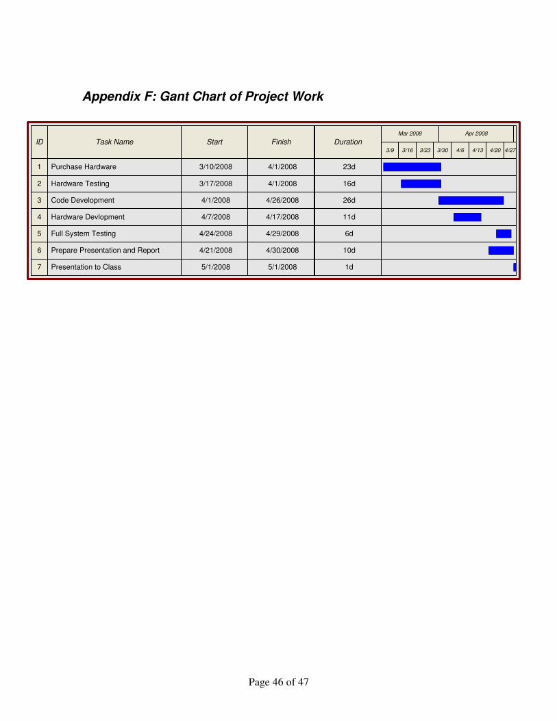
Appendix F: Gant Chart of Project Work
ID Task Name Start Finish Duration
Mar 2008 Apr 2008
3/9 3/16 3/23 3/30 4/6 4/13 4/20 4/27
1 23d4/1/20083/10/2008Purchase Hardware
2 16d4/1/20083/17/2008Hardware Testing
3 26d4/26/20084/1/2008Code Development
4 11d4/17/20084/7/2008Hardware Devlopment
5 6d4/29/20084/24/2008Full System Testing
6 10d4/30/20084/21/2008Prepare Presentation and Report
7 1d5/1/20085/1/2008Presentation to Class

Page 47 of 47
Final Presentation