Embed Size (px)
Citation preview

1 23
Machine Vision and Applications ISSN 0932-8092 Machine Vision and ApplicationsDOI 10.1007/s00138-012-0469-6
Pi-Tag: a fast image-space marker designbased on projective invariants
Filippo Bergamasco, Andrea Albarelli &Andrea Torsello

1 23
Your article is protected by copyright and
all rights are held exclusively by Springer-
Verlag Berlin Heidelberg. This e-offprint is
for personal use only and shall not be self-
archived in electronic repositories. If you
wish to self-archive your work, please use the
accepted author’s version for posting to your
own website or your institution’s repository.
You may further deposit the accepted author’s
version on a funder’s repository at a funder’s
request, provided it is not made publicly
available until 12 months after publication.
Machine Vision and ApplicationsDOI 10.1007/s00138-012-0469-6
ORIGINAL PAPER
Pi-Tag: a fast image-space marker design basedon projective invariants
Filippo Bergamasco · Andrea Albarelli ·Andrea Torsello
Received: 24 May 2012 / Revised: 1 November 2012 / Accepted: 14 November 2012© Springer-Verlag Berlin Heidelberg 2012
Abstract Visual marker systems have become anubiquitous tool to supply a reference frame onto otherwiseuncontrolled scenes. Throughout the last decades, a widerange of different approaches have emerged, each with dif-ferent strengths and limitations. Some tags are optimized toreach a high accuracy in the recovered camera pose, othersare based on designs that aim to maximizing the detectionspeed or minimizing the effect of occlusion on the detec-tion process. Most of them, however, employ a two-step pro-cedure where an initial homography estimation is used totranslate the marker from the image plane to an orthonormalworld, where it is validated and recognized. In this paper,we present a general purpose fiducial marker system thatperforms both steps directly in image-space. Specifically,by exploiting projective invariants such as collinearity andcross-ratios, we introduce a detection and recognition algo-rithm that is fast, accurate and moderately robust to occlu-sion. The overall performance of the system is evaluated inan extensive experimental section, where a comparison witha well-known baseline technique is presented. Additionally,several real-world applications are proposed, ranging fromcamera calibration to projector-based augmented reality.
Keywords Fiducial markers · Projective invariants ·Augmented reality · Pose estimation · Camera calibration
F. Bergamasco · A. Albarelli (B) · A. TorselloDipartimento di Scienze Ambientali, Informatica e Statistica,Università Ca’ Foscari Venezia, Venice, Italye-mail: [email protected]
F. Bergamascoe-mail: [email protected]
A. Torselloe-mail: [email protected]
1 Introduction
A visual marker is an artificial object consistent with aknown model that is placed into a scene to supply areference frame. Currently, such artefacts are unavoidablewhenever a high level of precision and repeatability in image-based measurement is required, as in the case of vision-driven dimensional assessment task such as robot navigationand SLAM [5,8,36], motion capture [2,38], pose estima-tion [37,39], camera calibration [7,14] and of course in fieldof augmented reality [6,40].
While in some scenarios, approaches based on naturallyoccurring features have been shown to yield satisfactoryresults, they still suffer from shortcomings that severely limittheir usability in uncontrolled environments. Specifically, thelack of a well-known model limits their use in pose estima-tion. In fact, while using techniques like bundle adjustmentcan recover part of the pose, the estimation can be only upto an unknown scale parameter; further, the accuracy of theestimation heavily depends on the correctness of localizationand matching steps.
Moreover, the availability and distinctiveness of naturalfeatures are not guaranteed at all. Indeed the smooth surfacesfound in most man-made objects can easily lead to scenes thatare very poor in features.
Finally, photometric inconsistencies due to reflective ortranslucent materials severely affect the repeatability of thepoint descriptors, jeopardizing the correct matching of thedetected points. For this reasons, it is not surprising that arti-ficial fiducial tags continue to be widely used and are still anactive research topic.
Markers are generally designed to be easily detected andrecognized in images produced by a pinhole camera. In thissense, they make heavy use of the projective invariance prop-erties of geometrical entities such as lines, planes and conics.
123
Author's personal copy
F. Bergamasco et al.
One of the earliest invariance used is probably the closureof the class of ellipses to projective transformations. Thisimplies that ellipses (and thus circles) in any pose in the 3Dworld appear as ellipses in the image plane. This allows bothfor an easy detection and a quite straightforward rectificationof the plane containing any circle.
With their seminal work, Gatrell et al. [10] propose to usea set of highly contrasted concentric circles and validate acandidate marker by analyzing the compatibility between thecentroids of the detected ellipses. By alternating white andblack circles, a few bits of information can be encoded inthe marker itself. In the work proposed in [3], the concentriccircle approach is enhanced by adding colors and multiplescales. Later, in [18] and [24], dedicated “data rings” areadded to the marker design.
A set of four circles located at the corner of a square isadopted in [4]: in this case, an identification pattern is placedin the middle of the four dots to distinguish between differenttargets. This ability to recognize all the viewed markers isreally important for complex scenes where more than a sin-gle fiducial is required; furthermore, the availability of a cod-ing scheme allows for an additional validation step and thuslowers the number of false positives.
Circular features are also adopted in [31], where a setof randomly placed dots are used to define distinguishablemarkers that can be detected and recognized without the needfor a frame. In this case, to attain robustness and to avoidwrong classification, a large number of dots are requiredfor each marker, thus leading to a likely high number ofRANSAC iterations.
Collinearity, that is the property of points that lie ona straight line of remaining aligned after any projectivetransformation, is another frequently used invariant. Almostinvariably this property is exploited by detecting the borderedges of a highly contrasted quadrilateral block. This hap-pens, for instance, with the very well-known ARToolkit [16]system which is freely available and has been adopted in
countless virtual reality applications. Thanks to the ease ofdetection and the high accuracy provided in pose recovery[21], this solution is adopted also in many recent marker sys-tems, such as ARTag [9] and ARToolkitPlus [35]. The lattertwo methods replace the recognition technique of ARToolkit,which is based on image correlation, with a binary-coded pat-tern (see Fig. 1).
Finally, many papers suggest the use of the cross-ratioamong detected points [33,20,28,30], or lines [32] as invari-ant properties around which to build marker systems. Aclear advantage of the cross-ratio is that, being a projec-tive invariant, the recognition can be made without the needof any rectification of the image. Unfortunately, the ease ofdetection offered by the use of the cross-ratio often comesat the price of a high sensitivity to occlusions or misde-tection. In fact, spurious or missing detection completelydestroy the invariant structure. Further, cross-ratios exhibit astrongly non-uniform distribution [13], which in several situ-ation limits the overall number of distinctively recognizablepatterns.
In this paper, we introduce a novel visual marker systemthat uses the cross-ratio and other projective invariants to per-form both detection and recognition in the image plane, with-out requiring the estimation of an homography or any othertechnique of perspective correction. Further, our approachintroduces some redundancy by replicating the same patternon different sides, which can be exploited to obtain a mod-erated robustness to occlusion or to lower the false positiverate. In addition, the detection and recognition algorithms areboth efficient and very simple to implement. In the experi-mental section, we validate the proposed approach by com-paring its performance with two widely used marker systemsunder a wide range of noise sources applied to syntheticallygenerated scenes. Finally, we also tested the effectiveness ofthe novel marker when dealing with real images using it tosolve a number of different real-world measurement tasksand applications.
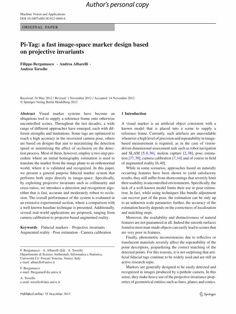
(a) (b) (c) (d) (e)
Fig. 1 Some examples of fiducial markers that differ both in the detec-tion technique and in the pattern used for recognition. The black squareborder enables detection in ARToolkit a and ARTag b, but whileARToolkit uses image correlation to differentiate markers, ARTag relieson error-correcting codes. In c detection happens by locating concentric
ellipses, while the eight sectors contained in them encode some infor-mation. In d, the detection happens directly in image-space using theangular cross-ratio between lines, but the pose estimation requires astereo camera. Finally, e shows an example of the proposed Pi-Tagwhich is detected and recognized in the image-space
123
Author's personal copy
Pi-Tag: a fast image-space marker design
2 Image-space fiducial markers
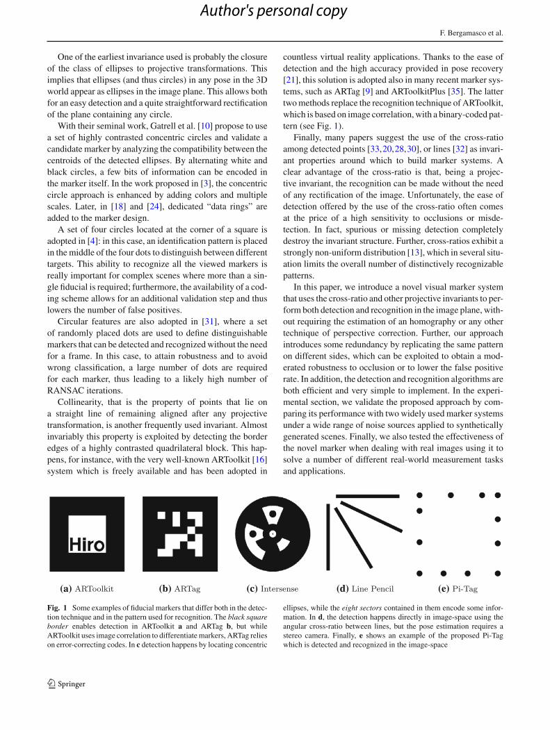
The proposed marker, which we named Pi-Tag (Projectiveinvariant Tag), exhibits a very simple design. It is made up of12 dots placed on the sides of a square: four dots per side, withthe corner dots shared. There are two distinct configurationsof the dots and each is repeated in two adjacent sides. See,for example, the marker in Fig. 1e: The top and left sidesshow the same configuration, and so do the bottom and rightones. The two different configurations are not random. In factthey are created in such a way that the cross-ratio of the twopatterns is proportional via a fixed constant δ.
The interplay between the detection of these cross-ratios inthe image plane and other invariants such as straight lines andconics projections allows for a simple and effective detectionand recognition approach for the Pi-Tag.
2.1 Projective invariants
Our approach relies on four types of projective invariants,namely the invariance of the class of ellipses, collinearity,angular ordering (on planes facing the view direction) andcross-ratio.
The invariance of the class of ellipses has been extensivelyexploited in literature. Circular dots are easy to produce and,since they appear as ellipses under any projective transfor-mation, they are also easy to detect by fitting on them a conicmodel with a low number of parameters. In addition, whilethe center of the detected ellipses is not preserved under per-spective, if the original dots are small enough, the localiza-tion error has been shown to be negligible for most practicalpurposes [22].
Other advantages of the elliptical fitting include the abilityof using the residual error to filter out false detections andto perform gradient-based refinements. For this and otherreasons, dots are widely adopted also for accurate tasks suchas lens distortion correction, and stereo calibration.
Given a set of points, projective geometry preservesneither distances nor the ratios between them. Fortunately,there are some interesting properties that remain invariantand can be put to use. One is the angular ordering of copla-nar points. That is, if we take three points defining a triangle,once we have established an ordering on them (either clock-wise or anti-clockwise), such ordering is maintained underany projective transformations that looks down to the sameside of the plane.
The second invariant is collinearity and derives from thefact that straight lines remain straight under perspective trans-formations. Almost all rectangular fiducial markers rely onthis property in the detection stage by finding lines in a sceneusing a wide range of different techniques.
Finally, we use the cross-ratio of four collinear pointsA,B,C and D, a projective invariant defined as:
Fig. 2 The cross-ratio of four collinear points is invariant to projectivetransformations. cr(A, B, C, D) = cr(A′, B ′, C ′, D′)
cr(A, B, C, D) = |AB|/|B D||AC |/|C D| , (1)
where |AB| denotes the Euclidean distance between pointsA and B (see Fig. 2).
The cross-ratio does not depend on the direction of theline ABC D, but depends on the order and the relative posi-tions between the points. The four points can be arranged in4! = 24 different orderings which yield six different cross-ratios. Due to this fact, the cross-ratio is unlikely to be useddirectly to match a candidate set of points against a spe-cific model, unless some information is available to assignan unique ordering to such points.
Many fiducial marker systems use projective and permu-tation P2-invariants [23] to eliminate the ambiguities of thedifferent orderings. For example, this invariants are used totrack markers or interaction devices for augmented realityin [33] and [19]. It has to be noted, however, that permu-tation invariance results in the inability to establish corre-spondences between the detected features and points in thereference model, making it impossible to fully estimate thecamera pose without relying to stereo image pairs or otherfeatures in the markers.
The main idea behind the design of the proposed Pi-Tags isto combine all the afore-mentioned invariants to identify eachdot without ambiguities, even in the presence of moderateocclusions, thus allowing fast and accurate pose estimation.To this end, it should be noted that we assume the imagingprocess to be projective. While this holds to a reasonableapproximation with many computer vision devices with goodlens and moderate focal length, wide angle cameras couldhinder our assumption due to lens distortion. In this case, aproper distortion-correcting calibration step [29] should beperformed before processing.
2.2 Marker detection and recognition
In our design, each marker is characterized by properties thatare common to all tags. Specifically, each side of the markermust be made up of exactly four dots, with the corner dotsbeing shared and labeled as in Fig. 3a. For a given constant δ,
123
Author's personal copy
F. Bergamasco et al.
(a) (b) (c)
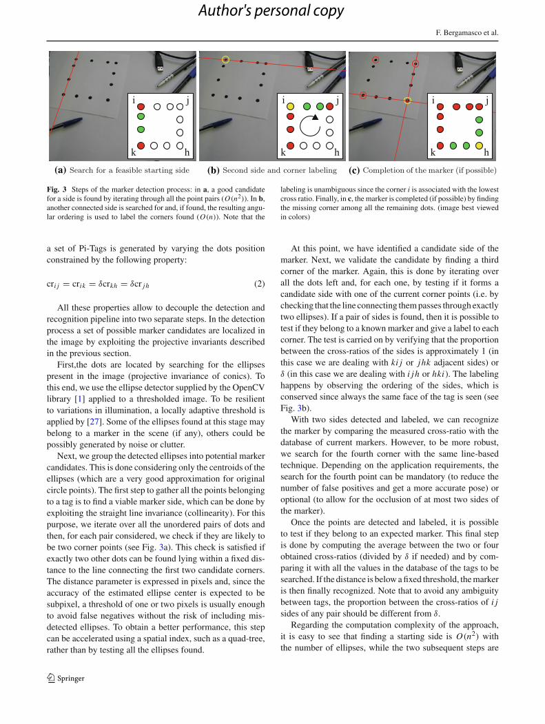
Fig. 3 Steps of the marker detection process: in a, a good candidatefor a side is found by iterating through all the point pairs (O(n2)). In b,another connected side is searched for and, if found, the resulting angu-lar ordering is used to label the corners found (O(n)). Note that the
labeling is unambiguous since the corner i is associated with the lowestcross ratio. Finally, in c, the marker is completed (if possible) by findingthe missing corner among all the remaining dots. (image best viewedin colors)
a set of Pi-Tags is generated by varying the dots positionconstrained by the following property:
cri j = crik = δcrkh = δcr jh (2)
All these properties allow to decouple the detection andrecognition pipeline into two separate steps. In the detectionprocess a set of possible marker candidates are localized inthe image by exploiting the projective invariants describedin the previous section.
First,the dots are located by searching for the ellipsespresent in the image (projective invariance of conics). Tothis end, we use the ellipse detector supplied by the OpenCVlibrary [1] applied to a thresholded image. To be resilientto variations in illumination, a locally adaptive threshold isapplied by [27]. Some of the ellipses found at this stage maybelong to a marker in the scene (if any), others could bepossibly generated by noise or clutter.
Next, we group the detected ellipses into potential markercandidates. This is done considering only the centroids of theellipses (which are a very good approximation for originalcircle points). The first step to gather all the points belongingto a tag is to find a viable marker side, which can be done byexploiting the straight line invariance (collinearity). For thispurpose, we iterate over all the unordered pairs of dots andthen, for each pair considered, we check if they are likely tobe two corner points (see Fig. 3a). This check is satisfied ifexactly two other dots can be found lying within a fixed dis-tance to the line connecting the first two candidate corners.The distance parameter is expressed in pixels and, since theaccuracy of the estimated ellipse center is expected to besubpixel, a threshold of one or two pixels is usually enoughto avoid false negatives without the risk of including mis-detected ellipses. To obtain a better performance, this stepcan be accelerated using a spatial index, such as a quad-tree,rather than by testing all the ellipses found.
At this point, we have identified a candidate side of themarker. Next, we validate the candidate by finding a thirdcorner of the marker. Again, this is done by iterating overall the dots left and, for each one, by testing if it forms acandidate side with one of the current corner points (i.e. bychecking that the line connecting them passes through exactlytwo ellipses). If a pair of sides is found, then it is possible totest if they belong to a known marker and give a label to eachcorner. The test is carried on by verifying that the proportionbetween the cross-ratios of the sides is approximately 1 (inthis case we are dealing with ki j or jhk adjacent sides) orδ (in this case we are dealing with i jh or hki). The labelinghappens by observing the ordering of the sides, which isconserved since always the same face of the tag is seen (seeFig. 3b).
With two sides detected and labeled, we can recognizethe marker by comparing the measured cross-ratio with thedatabase of current markers. However, to be more robust,we search for the fourth corner with the same line-basedtechnique. Depending on the application requirements, thesearch for the fourth point can be mandatory (to reduce thenumber of false positives and get a more accurate pose) oroptional (to allow for the occlusion of at most two sides ofthe marker).
Once the points are detected and labeled, it is possibleto test if they belong to an expected marker. This final stepis done by computing the average between the two or fourobtained cross-ratios (divided by δ if needed) and by com-paring it with all the values in the database of the tags to besearched. If the distance is below a fixed threshold, the markeris then finally recognized. Note that to avoid any ambiguitybetween tags, the proportion between the cross-ratios of i jsides of any pair should be different from δ.
Regarding the computation complexity of the approach,it is easy to see that finding a starting side is O(n2) withthe number of ellipses, while the two subsequent steps are
123
Author's personal copy

Pi-Tag: a fast image-space marker design
both O(n). This means that if each detected point triggersthe full chain the total complexity of the algorithm could betheoretically as high as O(n4). However, in practice, giventhe relatively low probability of getting four ellipses in linewith the correct cross ratio, most of the starting side foundlead to a correct detection. In addition, even when the startingside is not correct, it is highly probable that the cross-ratiocheck will stop the false matching at the second step.
While a full probabilistic study would give a more formalinsight, in the experimental section we will show that evenwith a large number of false ellipses the recognition is accu-rate and it is fast enough for real-time applications.
2.3 Estimation of the camera pose
Having detected and labeled the ellipses, it is now possibleto estimate the camera pose. Since the geometry of theoriginal marker is known, any algorithm that solves the PnPproblem can be used. In our tests, we used the solvePnP func-tion available in OpenCV. However, it should be noted that,while the estimated ellipse centers can be good enough forthe detection step, it is reasonable to refine them to recover amore accurate pose. Since this is done only when a marker isfound and recognized, the computational cost is limited. Inour experiments, we opted for the robust ellipse refinementapproach presented in [25].
In addition, to obtain a more accurate localization, onemight be tempted to correct the projective displacement ofthe ellipses centers. However, according to our tests, suchcorrection in general gives little advantage and sometimesleads to a slightly reduction in accuracy. Finally, we alsotried the direct method outlined in [15], but we obtained veryunstable results, especially with small and skewed ellipses.
3 Experimental validation
In this section, we evaluate the accuracy and speed of thePi-Tag fiducial markers and compare them with ARToolkitand ARToolkitPlus.
A first batch of tests is performed with syntheticallygenerated images under different condition of viewingdirection, noise, and blur. This allows us to compare thedifferent techniques with a perfect ground truth for thecamera pose, so that even slight differences in precision canbe detected. The accuracy of the recovered pose is measuredas the angular difference between the ground truth cameraorientation and the obtained pose. While this is a subset ofthe whole information related to the pose, this is an impor-tant parameter in many applications and allows for a conciseanalysis.
A second set of experiments is aimed at characterizing thebehaviour of Pi-Tags with respect to its resilience to occlu-
sion, the presence of false positives, and the sensitivity to thethreshold parameters, as well analyze computational timerequired by the approach.
Finally, four real-world application of the proposed tag arestudied; namely, we show the effectiveness of these markersas tools for contactless measurement, camera calibration, and3D surface alignment. In addition, we also describe a possibleuse of Pi-Tags with non-square aspect ratio for projectedaugmented reality applications.
The implementations of ARToolkit and ARToolkitPlusused are the ones freely available at the respective web-sites. The real images are taken with a 640×480 CMOSwebcam for the occlusion test and with a higher resolution1,280×1,024 CCD computer vision camera with a fixed focallength lens for the measurement tests.
All the experiments have been performed on a typi-cal desktop PC equipped with a 1.6 Ghz Intel Core Duoprocessor and 2 GB of RAM.
3.1 Accuracy and baseline comparisons
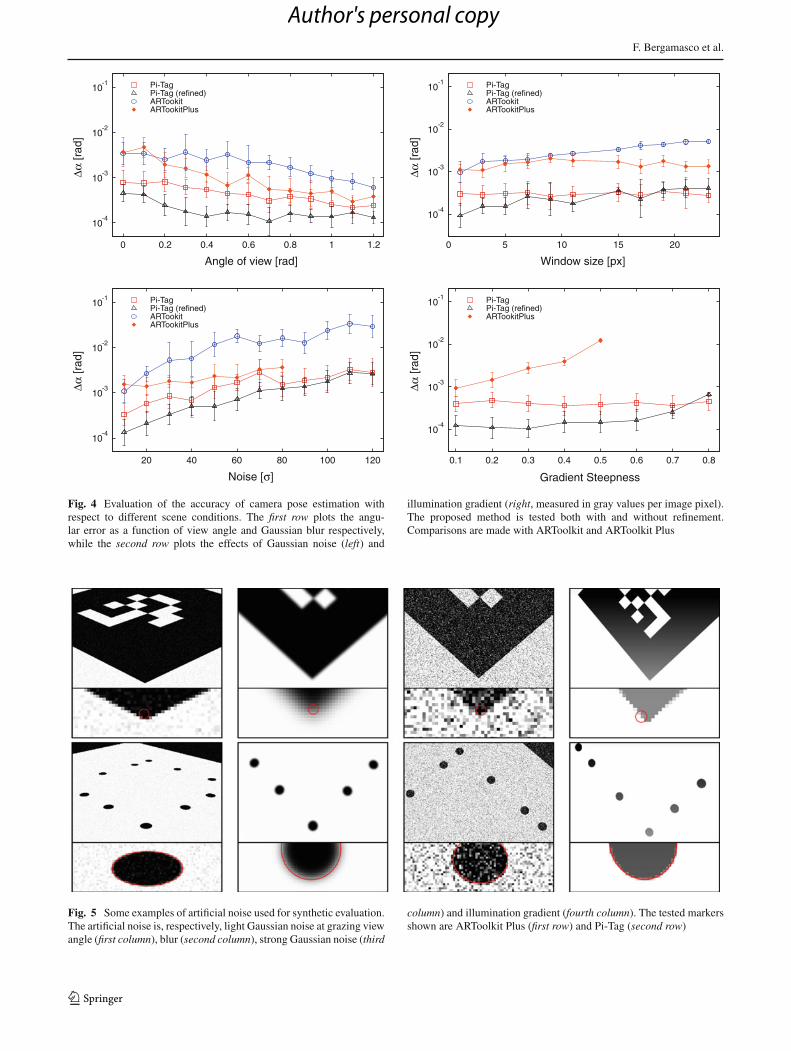
In Fig. 4, the accuracy of our markers is evaluated. In thefirst set of experiments, the marker is tested at increasinggrazing angles and with a minimal additive Gaussian noise.It is interesting to note that oblique angles lead to a higheraccuracy for all the methods, as long as the markers are stillrecognizable. This is explained by the stronger reprojectionconstraint imposed by angled shots with respect to almostorthogonal views. Pi-Tag shows better results both when thepose is evaluated with the original thresholded ellipses andafter the refinement.
In the second test, we evaluated the effects of Gaussianblur, which appears to have a limited effect on all thetechniques. This is mainly related to the fact that allmethods perform a preliminary edge detection step, whichin turn applies a convolution kernel. Hence, it is some-what expected that an additional blur does not affectmuch the marker localization. In the third test, an addi-tive Gaussian noise was added to images with an aver-age view angle of 0.3 radians and no artificial blur wasadded.
The performance of all methods decreases with increas-ing levels of noise and ARToolkitPlus, while in general moreaccurate than ARToolkit, breaks when dealing with a noisewith a standard deviation greater than 80 (pixel intensitiesgoes from 0 to 255). Finally, the effect of illumination gra-dient is tested only against ARToolkitPlus (since ARToolkitcannot handle this kind of noise), which, again, exhibits loweraccuracy and breaks with just moderate gradients (Fig. 5).
Overall, these experiments confirm that Pi-Tag outper-forms the alternative marker systems. This is probably dueboth to the higher number of pinpointed features and to the
123
Author's personal copy
F. Bergamasco et al.
10-4
10-3
10-2
10-1
0 0.2 0.4 0.6 0.8 1 1.2
Δα [r
ad]
Angle of view [rad]
Pi-TagPi-Tag (refined)ARTookitARTookitPlus
10-4
10-3
10-2
10-1
0 5 10 15 20
Δα [r
ad]
Window size [px]
Pi-TagPi-Tag (refined)ARTookitARTookitPlus
10-4
10-3
10-2
10-1
20 40 60 80 100 120
Δα [r
ad]
Noise [σ]
Pi-TagPi-Tag (refined)ARTookitARTookitPlus
10-4
10-3
10-2
10-1
0.1 0.2 0.3 0.4 0.5 0.6 0.7 0.8
Δα [r
ad]
Gradient Steepness
Pi-TagPi-Tag (refined)ARTookitPlus
Fig. 4 Evaluation of the accuracy of camera pose estimation withrespect to different scene conditions. The first row plots the angu-lar error as a function of view angle and Gaussian blur respectively,while the second row plots the effects of Gaussian noise (left) and
illumination gradient (right, measured in gray values per image pixel).The proposed method is tested both with and without refinement.Comparisons are made with ARToolkit and ARToolkit Plus
Fig. 5 Some examples of artificial noise used for synthetic evaluation.The artificial noise is, respectively, light Gaussian noise at grazing viewangle (first column), blur (second column), strong Gaussian noise (third
column) and illumination gradient (fourth column). The tested markersshown are ARToolkit Plus (first row) and Pi-Tag (second row)
123
Author's personal copy
Pi-Tag: a fast image-space marker design
better accuracy attainable using circular patterns rather thancorners [22].
In practical terms, the improvement is not negligible. Infact an error as low as 10−3 radians still produces a jitterof 1 millimetre when projected over a distance of 1 meter.While this is a reasonable performance for augmented real-ity applications, it is unacceptable for precise contactlessmeasurements.
3.2 Resilience to occlusion and false ellipses
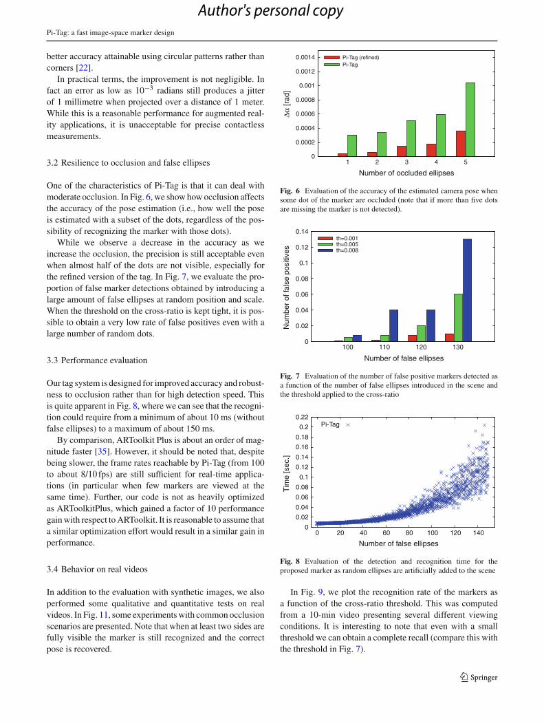
One of the characteristics of Pi-Tag is that it can deal withmoderate occlusion. In Fig. 6, we show how occlusion affectsthe accuracy of the pose estimation (i.e., how well the poseis estimated with a subset of the dots, regardless of the pos-sibility of recognizing the marker with those dots).
While we observe a decrease in the accuracy as weincrease the occlusion, the precision is still acceptable evenwhen almost half of the dots are not visible, especially forthe refined version of the tag. In Fig. 7, we evaluate the pro-portion of false marker detections obtained by introducing alarge amount of false ellipses at random position and scale.When the threshold on the cross-ratio is kept tight, it is pos-sible to obtain a very low rate of false positives even with alarge number of random dots.
3.3 Performance evaluation
Our tag system is designed for improved accuracy and robust-ness to occlusion rather than for high detection speed. Thisis quite apparent in Fig. 8, where we can see that the recogni-tion could require from a minimum of about 10 ms (withoutfalse ellipses) to a maximum of about 150 ms.
By comparison, ARToolkit Plus is about an order of mag-nitude faster [35]. However, it should be noted that, despitebeing slower, the frame rates reachable by Pi-Tag (from 100to about 8/10 fps) are still sufficient for real-time applica-tions (in particular when few markers are viewed at thesame time). Further, our code is not as heavily optimizedas ARToolkitPlus, which gained a factor of 10 performancegain with respect to ARToolkit. It is reasonable to assume thata similar optimization effort would result in a similar gain inperformance.
3.4 Behavior on real videos
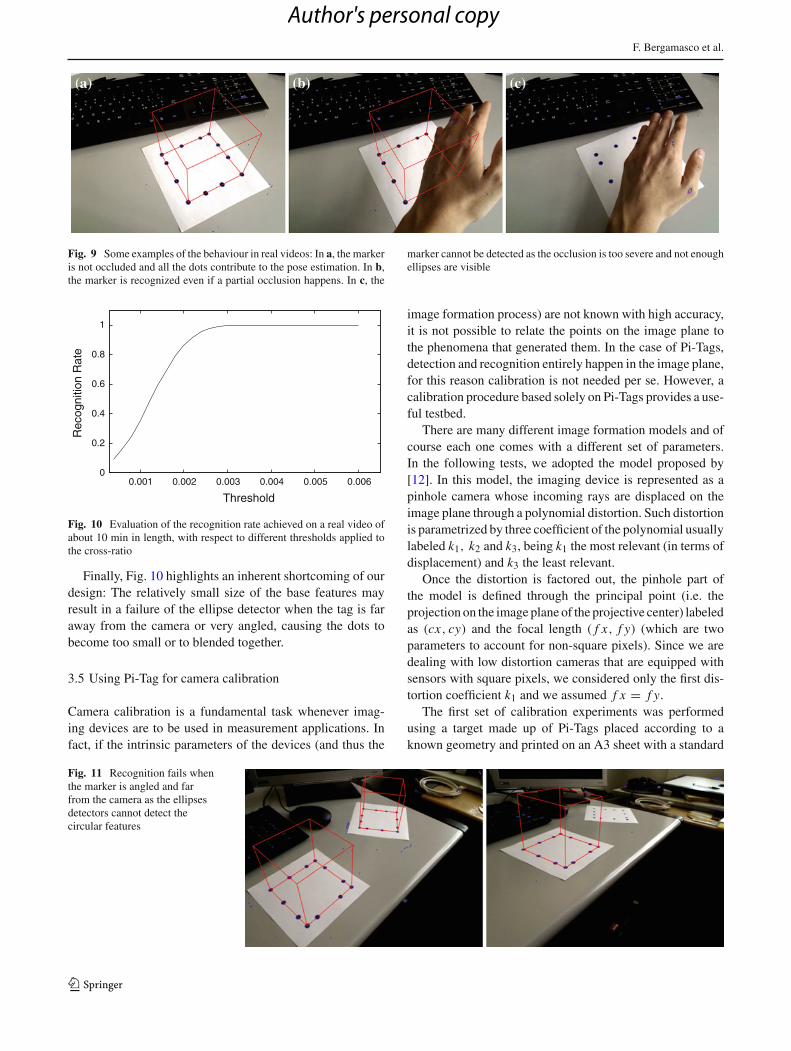
In addition to the evaluation with synthetic images, we alsoperformed some qualitative and quantitative tests on realvideos. In Fig. 11, some experiments with common occlusionscenarios are presented. Note that when at least two sides arefully visible the marker is still recognized and the correctpose is recovered.
0
0.0002
0.0004
0.0006
0.0008
0.001
0.0012
0.0014
1 2 3 4 5
Δα [r
ad]
Number of occluded ellipses
Pi-Tag (refined)Pi-Tag
Fig. 6 Evaluation of the accuracy of the estimated camera pose whensome dot of the marker are occluded (note that if more than five dotsare missing the marker is not detected).
0
0.02
0.04
0.06
0.08
0.1
0.12
0.14
100 110 120 130
Num
ber
of fa
lse
posi
tives
Number of false ellipses
th=0.001th=0.005th=0.008
Fig. 7 Evaluation of the number of false positive markers detected asa function of the number of false ellipses introduced in the scene andthe threshold applied to the cross-ratio
0
0.02
0.04
0.06
0.08
0.1
0.12
0.14
0.16
0.18
0.2
0.22
0 20 40 60 80 100 120 140
Tim
e [s
ec.]
Number of false ellipses
Pi-Tag
Fig. 8 Evaluation of the detection and recognition time for theproposed marker as random ellipses are artificially added to the scene
In Fig. 9, we plot the recognition rate of the markers asa function of the cross-ratio threshold. This was computedfrom a 10-min video presenting several different viewingconditions. It is interesting to note that even with a smallthreshold we can obtain a complete recall (compare this withthe threshold in Fig. 7).
123
Author's personal copy
F. Bergamasco et al.
Fig. 9 Some examples of the behaviour in real videos: In a, the markeris not occluded and all the dots contribute to the pose estimation. In b,the marker is recognized even if a partial occlusion happens. In c, the
marker cannot be detected as the occlusion is too severe and not enoughellipses are visible
0
0.2
0.4
0.6
0.8
1
0.001 0.002 0.003 0.004 0.005 0.006
Rec
ogni
tion
Rat
e
Threshold
Fig. 10 Evaluation of the recognition rate achieved on a real video ofabout 10 min in length, with respect to different thresholds applied tothe cross-ratio
Finally, Fig. 10 highlights an inherent shortcoming of ourdesign: The relatively small size of the base features mayresult in a failure of the ellipse detector when the tag is faraway from the camera or very angled, causing the dots tobecome too small or to blended together.
3.5 Using Pi-Tag for camera calibration
Camera calibration is a fundamental task whenever imag-ing devices are to be used in measurement applications. Infact, if the intrinsic parameters of the devices (and thus the
image formation process) are not known with high accuracy,it is not possible to relate the points on the image plane tothe phenomena that generated them. In the case of Pi-Tags,detection and recognition entirely happen in the image plane,for this reason calibration is not needed per se. However, acalibration procedure based solely on Pi-Tags provides a use-ful testbed.
There are many different image formation models and ofcourse each one comes with a different set of parameters.In the following tests, we adopted the model proposed by[12]. In this model, the imaging device is represented as apinhole camera whose incoming rays are displaced on theimage plane through a polynomial distortion. Such distortionis parametrized by three coefficient of the polynomial usuallylabeled k1, k2 and k3, being k1 the most relevant (in terms ofdisplacement) and k3 the least relevant.
Once the distortion is factored out, the pinhole part ofthe model is defined through the principal point (i.e. theprojection on the image plane of the projective center) labeledas (cx, cy) and the focal length ( f x, f y) (which are twoparameters to account for non-square pixels). Since we aredealing with low distortion cameras that are equipped withsensors with square pixels, we considered only the first dis-tortion coefficient k1 and we assumed f x = f y.
The first set of calibration experiments was performedusing a target made up of Pi-Tags placed according to aknown geometry and printed on an A3 sheet with a standard
Fig. 11 Recognition fails whenthe marker is angled and farfrom the camera as the ellipsesdetectors cannot detect thecircular features
123
Author's personal copy
Pi-Tag: a fast image-space marker design
Fig. 12 Evaluation of the quality of mono and stereo calibration obtained using Pi-Tags as fiducial markers
123
Author's personal copy
F. Bergamasco et al.
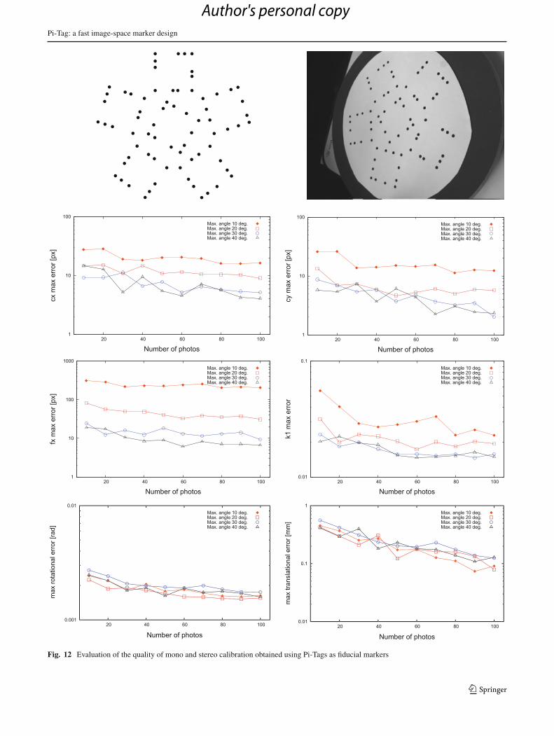
inkjet printer (see Fig. 12). Several shots of the target werecaptured with different viewing angles and at different dis-tances. For each shot the tags were detected and recognized,and an association between the 2D points on the image planeand the 3D point of the known model was stored. These datawere finally fed to the camera calibration procedure availablein the OpenCV library. Since both the target viewing angleand the number of shots are relevant factors for the qualityof the calibration, we studied the effect of both.
In the first four graphs of Fig. 12, we show the absolute dis-tance between the parameters recovered with the describedprocedure and a ground truth calibration performed with afull checkerboard pattern with about 600 reference cornerand using 200 shots. Specifically, for each number of shotsand maximum angle we selected 30 random set of images tobe used for calibration.
The distance plotted in the graph is the maximum absoluteerror committed in the 30 calibrations. From these graphs, it ispossible to see that taking shots with a large enough viewingangles is important. This is due both to the stronger constraintoffered to pinhole parameters by angled targets, and to themore accurate pose estimation offered by Pi-Tag when theangle of view is not negligible (see Fig. 4). In addition, we canalso observe that taking a large number of samples increasesmonotonically the accuracy obtained.
In the second set of calibration experiments, the tagswere used to estimate the relative pose between two camerasof known intrinsic model. This stereo calibration is usefulin many reconstruction tasks where the epipolar geometrybetween more than one camera can be exploited to fullylocalize the 3D points that are imaged (see [11]).
Again, we estimated a ground truth relative pose betweena pair of identical fixed cameras using a specialized target andplotted on the bottom row of Fig. 12 the maximum absoluteerror between the ground truth and the values obtained in20 calibrations performed on randomly selected shots with a
given maximum viewing angle. In this condition, the viewingangle is less important, but still a large number of shots givesbetter results.
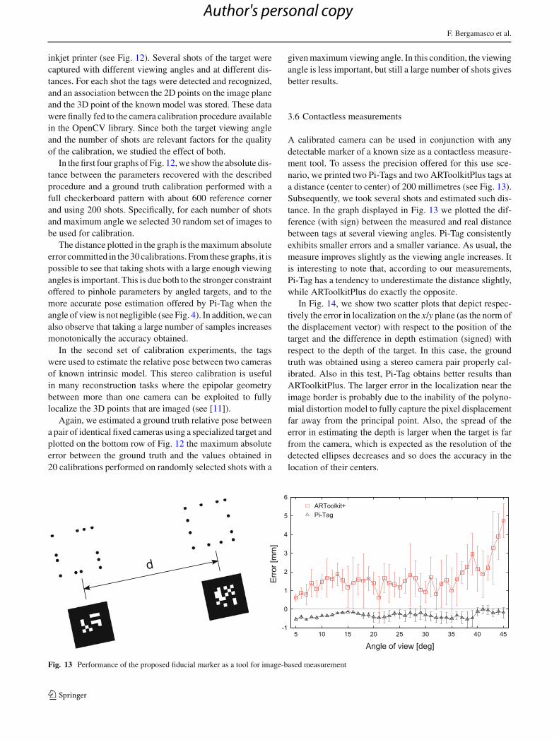
3.6 Contactless measurements
A calibrated camera can be used in conjunction with anydetectable marker of a known size as a contactless measure-ment tool. To assess the precision offered for this use sce-nario, we printed two Pi-Tags and two ARToolkitPlus tags ata distance (center to center) of 200 millimetres (see Fig. 13).Subsequently, we took several shots and estimated such dis-tance. In the graph displayed in Fig. 13 we plotted the dif-ference (with sign) between the measured and real distancebetween tags at several viewing angles. Pi-Tag consistentlyexhibits smaller errors and a smaller variance. As usual, themeasure improves slightly as the viewing angle increases. Itis interesting to note that, according to our measurements,Pi-Tag has a tendency to underestimate the distance slightly,while ARToolkitPlus do exactly the opposite.
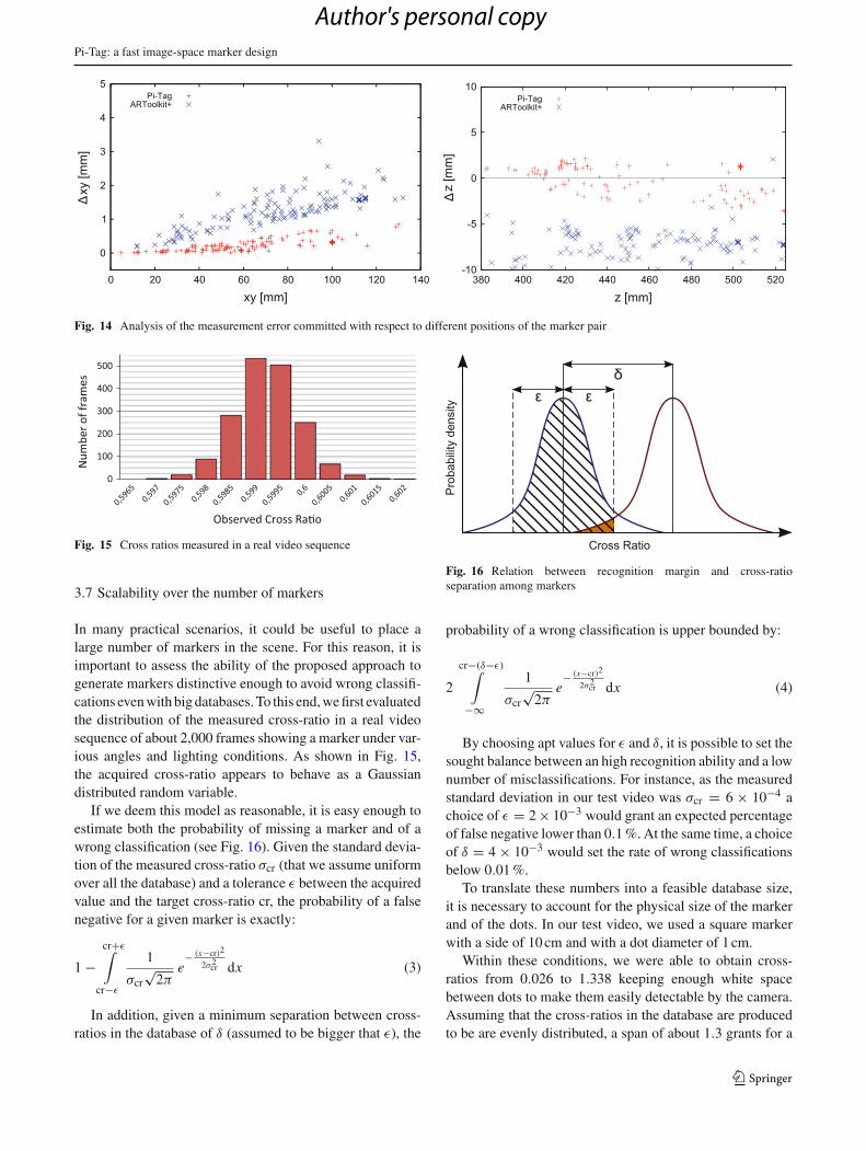
In Fig. 14, we show two scatter plots that depict respec-tively the error in localization on the x/y plane (as the norm ofthe displacement vector) with respect to the position of thetarget and the difference in depth estimation (signed) withrespect to the depth of the target. In this case, the groundtruth was obtained using a stereo camera pair properly cal-ibrated. Also in this test, Pi-Tag obtains better results thanARToolkitPlus. The larger error in the localization near theimage border is probably due to the inability of the polyno-mial distortion model to fully capture the pixel displacementfar away from the principal point. Also, the spread of theerror in estimating the depth is larger when the target is farfrom the camera, which is expected as the resolution of thedetected ellipses decreases and so does the accuracy in thelocation of their centers.
Fig. 13 Performance of the proposed fiducial marker as a tool for image-based measurement
123
Author's personal copy
Pi-Tag: a fast image-space marker design
Fig. 14 Analysis of the measurement error committed with respect to different positions of the marker pair
Fig. 15 Cross ratios measured in a real video sequence
3.7 Scalability over the number of markers
In many practical scenarios, it could be useful to place alarge number of markers in the scene. For this reason, it isimportant to assess the ability of the proposed approach togenerate markers distinctive enough to avoid wrong classifi-cations even with big databases. To this end, we first evaluatedthe distribution of the measured cross-ratio in a real videosequence of about 2,000 frames showing a marker under var-ious angles and lighting conditions. As shown in Fig. 15,the acquired cross-ratio appears to behave as a Gaussiandistributed random variable.
If we deem this model as reasonable, it is easy enough toestimate both the probability of missing a marker and of awrong classification (see Fig. 16). Given the standard devia-tion of the measured cross-ratio σcr (that we assume uniformover all the database) and a tolerance ε between the acquiredvalue and the target cross-ratio cr, the probability of a falsenegative for a given marker is exactly:
1 −cr+ε∫
cr−ε
1
σcr√
2πe− (x−cr)2
2σ2cr dx (3)
In addition, given a minimum separation between cross-ratios in the database of δ (assumed to be bigger that ε), the
Fig. 16 Relation between recognition margin and cross-ratioseparation among markers
probability of a wrong classification is upper bounded by:
2
cr−(δ−ε)∫
−∞
1
σcr√
2πe− (x−cr)2
2σ2cr dx (4)
By choosing apt values for ε and δ, it is possible to set thesought balance between an high recognition ability and a lownumber of misclassifications. For instance, as the measuredstandard deviation in our test video was σcr = 6 × 10⁻⁴ achoice of ε = 2 × 10⁻³ would grant an expected percentageof false negative lower than 0.1 %. At the same time, a choiceof δ = 4 × 10⁻³ would set the rate of wrong classificationsbelow 0.01 %.
To translate these numbers into a feasible database size,it is necessary to account for the physical size of the markerand of the dots. In our test video, we used a square markerwith a side of 10 cm and with a dot diameter of 1 cm.
Within these conditions, we were able to obtain cross-ratios from 0.026 to 1.338 keeping enough white spacebetween dots to make them easily detectable by the camera.Assuming that the cross-ratios in the database are producedto be are evenly distributed, a span of about 1.3 grants for a
123
Author's personal copy
F. Bergamasco et al.
total of about 300 distinct markers with the above-mentionedlevels of false negatives and wrong classifications.
3.8 Registration of 3D surfaces
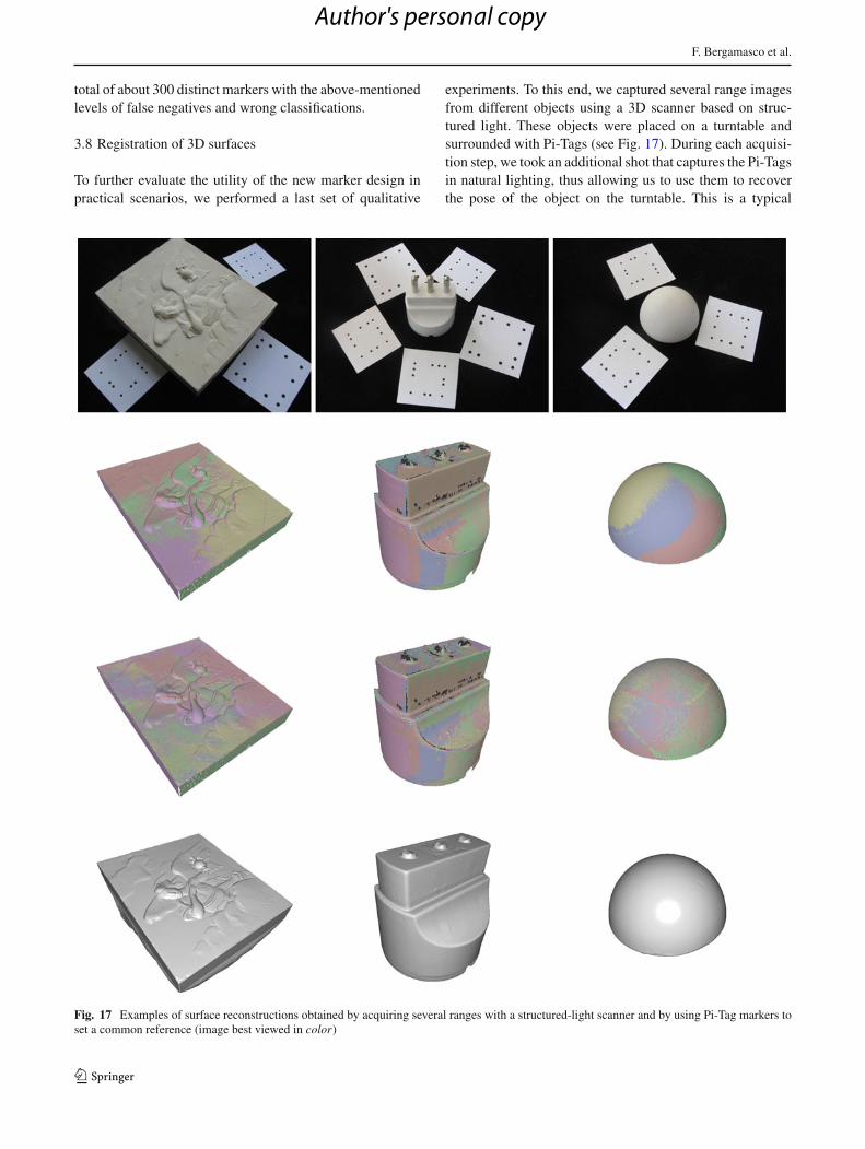
To further evaluate the utility of the new marker design inpractical scenarios, we performed a last set of qualitative
experiments. To this end, we captured several range imagesfrom different objects using a 3D scanner based on struc-tured light. These objects were placed on a turntable andsurrounded with Pi-Tags (see Fig. 17). During each acquisi-tion step, we took an additional shot that captures the Pi-Tagsin natural lighting, thus allowing us to use them to recoverthe pose of the object on the turntable. This is a typical
Fig. 17 Examples of surface reconstructions obtained by acquiring several ranges with a structured-light scanner and by using Pi-Tag markers toset a common reference (image best viewed in color)
123
Author's personal copy
Pi-Tag: a fast image-space marker design
application of artificial markers, since most algorithms usedto align 3D surfaces need a good initial motion estimationto guarantee a correct convergence. In the second row ofFig. 17, we show the overlap of several ranges using thepose estimated with Pi-Tags, without any further refinement.In the third row, the initial alignment is refined using astate-of-the-art variant of the well-known ICP algorithm (see[26]). After the refinement, slight improvements in the reg-istration can be appreciated, especially in the “hemisphere”object. The smooth blending of colors obtained means thatICP was able to obtain a good alignment, which in turntestifies the quality of the initial pose estimated using thePi-Tags. In the last row, we present the watertight surfaceobtained after applying the Poisson surface reconstructionalgorithm [17] to the aligned range images. Overall, the sur-faces are smooth and do not exhibit the typical artefactsrelated to misalignment. In addition, the fine details of thefirst object are preserved.
3.9 Applications in projected augmented reality
An interesting property of the proposed tag design is thatthere is no need for it to be square. In fact, any aspect ratiocan be adopted without compromising the properties of thecross ratio that are needed for the recognition of the tag andfor the pose estimation. We combined this exact propertywith the fact that the inside of the tag is blank (as with otherframe-based designs [34]) to build an additional applicationwithin the domain of the projected augmented reality.
Specifically, we built a system where a Pi-Tag is used bothas a passive input device and as a display. The input devicecan be regarded as a 3D mouse that can be used to exploreinteractive content. The ability to display data on the tag isobtained using an external projector that is aimed toward thewhite surface internal to the tag.
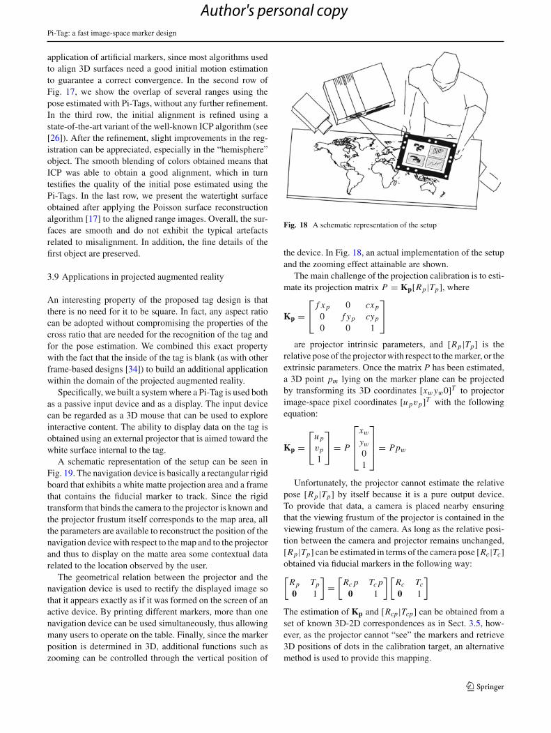
A schematic representation of the setup can be seen inFig. 19. The navigation device is basically a rectangular rigidboard that exhibits a white matte projection area and a framethat contains the fiducial marker to track. Since the rigidtransform that binds the camera to the projector is known andthe projector frustum itself corresponds to the map area, allthe parameters are available to reconstruct the position of thenavigation device with respect to the map and to the projectorand thus to display on the matte area some contextual datarelated to the location observed by the user.
The geometrical relation between the projector and thenavigation device is used to rectify the displayed image sothat it appears exactly as if it was formed on the screen of anactive device. By printing different markers, more than onenavigation device can be used simultaneously, thus allowingmany users to operate on the table. Finally, since the markerposition is determined in 3D, additional functions such aszooming can be controlled through the vertical position of
Fig. 18 A schematic representation of the setup
the device. In Fig. 18, an actual implementation of the setupand the zooming effect attainable are shown.
The main challenge of the projection calibration is to esti-mate its projection matrix P = Kp[Rp|Tp], where
Kp =⎡⎣ f x p 0 cx p
0 f yp cyp
0 0 1
⎤⎦
are projector intrinsic parameters, and [Rp|Tp] is therelative pose of the projector with respect to the marker, or theextrinsic parameters. Once the matrix P has been estimated,a 3D point pm lying on the marker plane can be projectedby transforming its 3D coordinates [xw yw0]T to projectorimage-space pixel coordinates [u pvp]T with the followingequation:
Kp =⎡⎣u p
vp
1
⎤⎦ = P
⎡⎢⎢⎣
xw
yw
01
⎤⎥⎥⎦ = Ppw
Unfortunately, the projector cannot estimate the relativepose [Rp|Tp] by itself because it is a pure output device.To provide that data, a camera is placed nearby ensuringthat the viewing frustum of the projector is contained in theviewing frustum of the camera. As long as the relative posi-tion between the camera and projector remains unchanged,[Rp|Tp] can be estimated in terms of the camera pose [Rc|Tc]obtained via fiducial markers in the following way:[
Rp Tp
0 1
]=
[Rc p Tc p
0 1
] [Rc Tc
0 1
]
The estimation of Kp and [Rcp|Tcp] can be obtained from aset of known 3D-2D correspondences as in Sect. 3.5, how-ever, as the projector cannot “see” the markers and retrieve3D positions of dots in the calibration target, an alternativemethod is used to provide this mapping.
123
Author's personal copy
F. Bergamasco et al.
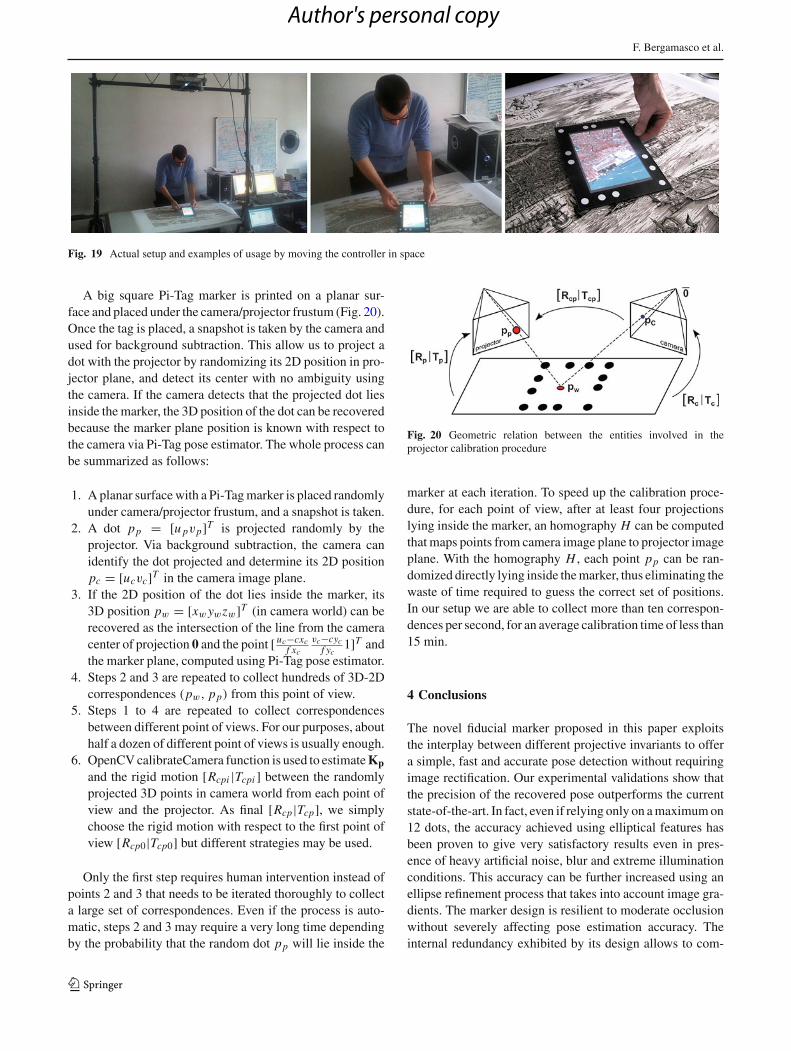
Fig. 19 Actual setup and examples of usage by moving the controller in space
A big square Pi-Tag marker is printed on a planar sur-face and placed under the camera/projector frustum (Fig. 20).Once the tag is placed, a snapshot is taken by the camera andused for background subtraction. This allow us to project adot with the projector by randomizing its 2D position in pro-jector plane, and detect its center with no ambiguity usingthe camera. If the camera detects that the projected dot liesinside the marker, the 3D position of the dot can be recoveredbecause the marker plane position is known with respect tothe camera via Pi-Tag pose estimator. The whole process canbe summarized as follows:
1. A planar surface with a Pi-Tag marker is placed randomlyunder camera/projector frustum, and a snapshot is taken.
2. A dot pp = [u pvp]T is projected randomly by theprojector. Via background subtraction, the camera canidentify the dot projected and determine its 2D positionpc = [ucvc]T in the camera image plane.
3. If the 2D position of the dot lies inside the marker, its3D position pw = [xw ywzw]T (in camera world) can berecovered as the intersection of the line from the cameracenter of projection 0 and the point [ uc−cxc
f xc
vc−cycf yc
1]T andthe marker plane, computed using Pi-Tag pose estimator.
4. Steps 2 and 3 are repeated to collect hundreds of 3D-2Dcorrespondences (pw, pp) from this point of view.
5. Steps 1 to 4 are repeated to collect correspondencesbetween different point of views. For our purposes, abouthalf a dozen of different point of views is usually enough.
6. OpenCV calibrateCamera function is used to estimate Kp
and the rigid motion [Rcpi |Tcpi ] between the randomlyprojected 3D points in camera world from each point ofview and the projector. As final [Rcp|Tcp], we simplychoose the rigid motion with respect to the first point ofview [Rcp0|Tcp0] but different strategies may be used.
Only the first step requires human intervention instead ofpoints 2 and 3 that needs to be iterated thoroughly to collecta large set of correspondences. Even if the process is auto-matic, steps 2 and 3 may require a very long time dependingby the probability that the random dot pp will lie inside the
Fig. 20 Geometric relation between the entities involved in theprojector calibration procedure
marker at each iteration. To speed up the calibration proce-dure, for each point of view, after at least four projectionslying inside the marker, an homography H can be computedthat maps points from camera image plane to projector imageplane. With the homography H , each point pp can be ran-domized directly lying inside the marker, thus eliminating thewaste of time required to guess the correct set of positions.In our setup we are able to collect more than ten correspon-dences per second, for an average calibration time of less than15 min.
4 Conclusions
The novel fiducial marker proposed in this paper exploitsthe interplay between different projective invariants to offera simple, fast and accurate pose detection without requiringimage rectification. Our experimental validations show thatthe precision of the recovered pose outperforms the currentstate-of-the-art. In fact, even if relying only on a maximum on12 dots, the accuracy achieved using elliptical features hasbeen proven to give very satisfactory results even in pres-ence of heavy artificial noise, blur and extreme illuminationconditions. This accuracy can be further increased using anellipse refinement process that takes into account image gra-dients. The marker design is resilient to moderate occlusionwithout severely affecting pose estimation accuracy. Theinternal redundancy exhibited by its design allows to com-
123
Author's personal copy
Pi-Tag: a fast image-space marker design
pensate the strongly non-uniform distribution of cross-ratioand also permits a good trade-off between the recognitionrate and false-positives. Even taking into account the limitednumber of discriminable cross-ratios, the design still offersa reasonable number of distinct tags. Further, the proposeddesign leaves plenty of space in the marker interior for anyadditional payload. Since it works entirely in image-space,our method is affected by image resolution only during theellipse detection step, and is fast enough for most real-timeaugmented reality applications.
Of course, those enhancements do not come without somedrawbacks. Specifically, the small size of the circular pointsused can lead the ellipse detector to miss them at great dis-tance, low resolution, or if the viewing point is very angledwith respect to the marker’s plane. These limitations can bepartially overcome by increasing the ratio between the sizeof the ellipses and the size of the marker itself, thus limitingthe range of possible cross-ratio values and the total numberof different tags that can be successfully recognized.
References
1. Bradski, G., Kaehler, A.: Learning OpenCV: Computer Vision withthe OpenCV Library, 1st edn. O’Reilly Media, Inc., Cambridge(2008)
2. Cameron, J., Lasenby, J.: Estimating human skeleton parametersand configuration in real-time from markered optical motioncapture. In: Conference on Articulated Motion and DeformableObjects (2008)
3. Cho, Y., Lee, J., Neumann, U.: A multi-ring color fiducial systemand a rule-based detection method for scalable fiducial-trackingaugmented reality. In: Proceedings of International Workshop onAugmented Reality (1998)
4. Claus, D., Fitzgibbon, A.W.: Reliable automatic calibration of amarker-based position tracking system. In: IEEE Workshop onApplications of Computer Vision (2005)
5. Davison, A.J., Reid, I.D., Molton, N.D., Stasse, O.: Monoslam:real-time single camera slam. IEEE Trans. Pattern Anal. Mach.Intell. 26(6), 1052–1067 (2007)
6. Dorfmller, K.: Robust tracking for augmented reality using retrore-flective markers. Comput. Graph. 23(6), 795–800 (1999)
7. Douxchamps, D., Chihara, K.: High-accuracy and robust local-ization of large control markers for geometric camera calibration.IEEE Trans. Pattern Anal. Mach. Intell. 31, 376–383 (2009)
8. Fiala, M.: Linear markers for robot navigation with panoramicvision. In: Proceedings of the 1st Canadian Conference on Com-puter and Robot Vision, CRV ’04, pp. 145–154. IEEE ComputerSociety, Washington, DC (2004)
9. Fiala, M.: Designing highly reliable fiducial markers. IEEE Trans.Pattern Anal. Mach. Intell. 32(7), 1317–1324 (2010)
10. Gatrell, L., Hoff, W., Sklair, C.: Robust image features: concen-tric contrasting circles and their image extraction. In: Proceedingsof Cooperative Intelligent Robotics in Space. SPIE, Washington(1991)
11. Hartley, R.I., Zisserman, A.: Multiple View Geometry in ComputerVision. Cambridge University Press, Cambridge (2000)
12. Heikkilä, J.: Geometric camera calibration using circular controlpoints. IEEE Trans. Pattern Anal. Mach. Intell. 22, 1066–1077(October 2000)
13. Huynh, D.Q.: The cross ratio: a revisit to its probability densityfunction. In: Proceedings of the British Machine Vision ConferenceBMVC 2000 (2000)
14. Jiang, G., Quan, L.: Detection of concentric circles for cameracalibration. IEEE Int. Conf. Comput. Vis. 1, 333–340 (2005)
15. Kannala, J., Salo, M.,: Heikkilä, J.: Algorithms for computinga planar homography from conics in correspondence. In: BritishMachine Vision Conference (2006)
16. Kato, H., Billinghurst, M.: Marker tracking and hmd calibrationfor a video-based augmented reality conferencing system. In: Pro-ceedings of the 2nd IEEE and ACM International Workshop onAugmented Reality. IEEE Computer Society, Washington, DC(1999)
17. Kazhdan, M., Bolitho, M., Hoppe, H.: Poisson surface recon-struction. In: Proceedings of the Fourth Eurographics sympo-sium on Geometry processing, SGP ’06, pp. 61–70. Aire-la-Ville,Switzerland (2006)
18. Knyaz, V.A. Head Of Group, Sibiryakov, R.V.: The develop-ment of new coded targets for automated point identification andnon-contact surface measurements. In: 3D Surface Measurements,International Archives of Photogrammetry and Remote Sensing(1998)
19. Li, Y., Wang, Y.-T., Liu, Y.: Fiducial marker based on projectiveinvariant for augmented reality. J. Comput. Sci. Technol. 22, 890–897 (2007)
20. Loaiza, M., Raposo, A., Gattass, M.: A novel optical trackingalgorithm for point-based projective invariant marker patterns. In:Proceedings of the 3rd International Conference on Advances inVisual Computing, vol. Part I, ISVC’07, pp. 160–169. Springer,Berlin (2007)
21. Maidi, M., Didier, J.-Y., Ababsa, F., Mallem, M.: A perfor-mance study for camera pose estimation using visual marker basedtracking. Mach. Vis. Appl. 21 (2010)
22. Mallon, J., Whelan, P.F.: Which pattern? biasing aspects of planarcalibration patterns and detection methods. Pattern Recogn. Lett.28(8), 921–930 (2007)
23. Meer, P., Lenz, R., Ramakrishna, S.: Efficient invariant represen-tations. Int. J. Comput. Vis. 26, 137–152 (1998)
24. Naimark, L., Foxlin, E.: Circular data matrix fiducial system androbust image processing for a wearable vision-inertial self-tracker.In: Proceedings of the 1st International Symposium on Mixed andAugmented Reality, ISMAR ’02. IEEE Computer Society, Wash-ington, DC (2002)
25. Ouellet, J., Hebert, P.: Precise ellipse estimation without contourpoint extraction. Mach. Vis. Appl. 21 (2009)
26. Rusinkiewicz, S., Levoy, M.: Efficient variants of the icp algorithm.In: Proceedings of the Third International Conference on 3D DigitalImaging and Modeling, pp. 145–152 (2001)
27. Sauvola, J., Pietikainen, M.: Adaptive document image binariza-tion. Pattern Recogn. 33(2), 225–236 (2000)
28. Teixeira, L., Loaiza, M., Raposo, A., Gattass, M.: Augmentedreality using projective invariant patterns. In: Advances in VisualComputing. Lecture Notes in Computer Science, vol. 5358.Springer, Berlin (2008)
29. Thormählen, T., Broszio, H.: Automatic line-based estimation ofradial lens distortion. Integr. Comput. Aided Eng. 12(2), 177–190(2005)
30. Tsonisp, V.S., Konstantinos, V.Ch., Trahaniaslj, P.E.: Landmark-based navigation using projective invariants. In: Proceedings ofthe 1998 IEEE International Conference on Intelligent Robots andSystems. IEEE Computer Society, Victoria, Canada (1998)
31. Uchiyama, H., Saito, H.: Random dot markers. In: Virtual RealityConference, IEEE, pp. 271–272 (2011)
32. van Rhijn, A., Mulder, J.D.: Optical tracking using line pencil fidu-cials. In: Proceedings of the Eurographics Symposium on VirtualEnvironments (2004)
123
Author's personal copy
F. Bergamasco et al.
33. Van Liere, R., Mulder, J.D.: Optical tracking using projectiveinvariant marker pattern properties. In: Proceedings of the IEEEVirtual Reality Conference. IEEE Press, New York (2003)
34. Wagner, D., Langlotz, T., Schmalstieg, D.: Robust and unobtru-sive marker tracking on mobile phones. In: Proceedings of the 7thIEEE/ACM International Symposium on Mixed and AugmentedReality, ISMAR ’08, pp. 121–124. IEEE Computer Society, Wash-ington, DC (2008)
35. Wagner, D., Reitmayr, G., Mulloni, A., Drummond, T.,Schmalstieg, D.: Real time detection and tracking for augmentedreality on mobile phones. IEEE Trans. Vis. Comput. Graph. 99,355–368 (2010)
36. Walthelm, A., Kluthe, R.: Active distance measurement based onrobust artificial markers as a building block for a service robotarchitecture. In: IFAC Symposium on Artificial Intelligence in RealTime Control. Budapest Polytechnic, Budapest (2000)
37. Yoon, J.-H., Park, J.-S., Kim, C.: Increasing camera pose estimationaccuracy using multiple markers. In: Advances in Artificial Realityand Tele-Existence. Lecture Notes in Computer Science, vol. 4282.pp. 239–248. Springer, Berlin (2006)
38. Yu, Q., Li, Q., Deng, Z.: Online motion capture marker labelingfor multiple interacting articulated targets. Comput. Graph. Forum26(3), 477–483 (2007)
39. Yu, R., Yang, T., Zheng, J., Zhang, X.: Real-time camera poseestimation based on multiple planar markers. In: Proceedings ofthe 2009 Fifth International Conference on Image and GraphicsICIG ’09, pp. 640–645. IEEE Computer Society, Washington, DC(2009)
40. Zhang, X., Fronz, S., Navab, N.: Visual marker detection anddecoding in ar systems: a comparative study. In: Proceedingsof the 1st International Symposium on Mixed and AugmentedReality, ISMAR ’02, pp. 97. IEEE Computer Society, Washington,DC (2002)
Author Biographies
Filippo Bergamasco receivedMSc degree (with honors) inComputer Science fromCa’Foscari University of Venice,Venice, Italy, in 2011 and iscurrently a PhD candidate atthe University Of Venice. Hisresearch interests are in thearea of computer vision, spread-ing from 3D reconstruction,Game-Theoretical approachesfor matching and clustering,structure from motion, aug-mented reality and photogram-metry. He has been involved in
many commercial computer vision projects for industries and entertain-ment, including structured light-scanner solutions, pipe measurementsystem for automotive, interactive vision-based museum exhibitionsand AR applications for embedded devices.
Andrea Albarelli received thePhD degree in Computer Sciencefrom the “Ca’ Foscari” Univer-sity of Venice in 2010, and iscurrently a PostDoc researcherin the same institution. His mainresearch area is within the fieldof computer vision and he haspublished around 40 technicalpapers in referred internationaljournals and conferences, mainlyrelated to the topics of Game-Theoretical approaches for solv-ing the matching problems and3D data acquisition and process-
ing. During the last academic years, he taught Information Theory andDigital Image Processing classes for both University of Padua and Uni-versity of Venice. He is also involved in several technological transferprojects and he is co-founder of an academic spin-off that offers vision-based industrial solutions.
Andrea Torsello received hisPhD in computer Science at theUniversity of York, UK and iscurrently working as AssistantProfessor at University Ca’ Fos-cari Venice, Italy. His researchinterests are in the areas of com-puter vision and pattern recogni-tion, in particular, the interplaybetween stochastic and structuralapproaches as well as Game-Theoretic models, with applica-tions in 3D reconstruction andrecognition. Dr. Torsello haspublished more than 80 technical
papers in refereed journals and conference proceedings and has beenin the program committees of numerous international conferences andworkshops. In 2011 he has been recognized as “Distinguished alumnus”by the University of York, UK. He held the position of chairman andis currently the vice-chair of the Technical Committee 15 of the Inter-national Association for Pattern Recognition, a technical committeedevoted to the promotion of research on Graph-based Representationsin Pattern Recognition.
123
Author's personal copy