Embed Size (px)
Citation preview

F SeriesGearmotor / Reducer
Hollow Shaft / Solid Shaft F
C1
FSeries
■Gearmotor / Gearmotor with Brake / Water-resistant, Outdoor (IP65) Gearmotor / Gearmotor with BrakeModel and Type Designation 0.1kW-0.4kWModel and Type Designation 0.75kW‒2.2kWModel and Type Designation 0.75kW‒2.2kWHollow Shaft Standard Model Lineup Indoor TypeHollow Shaft Standard Model Lineup Water-resistant TypeSolid Shaft Standard Model Lineup Indoor TypeHollow Shaft 3-Phase Performance TableSolid Shaft 3-Phase Performance TableHollow Shaft 3-Phase Outer Dimension DiagramSolid Shaft 3-Phase Outer Dimension DiagramHollow Shaft 1-Phase Performance TableHollow Shaft 1-Phase Outer Dimension Diagram
■Reducer (Double Shaft Type)Hollow Shaft Model and Type Designation Hollow Shaft Standard Model LineupHollow Shaft Performance TableHollow Shaft Outer Dimension Diagram
■S-Type Reducer (Designated Motor Attachable Type)Hollow Shaft Model and Type Designation Hollow Shaft Standard Model LineupHollow Shaft Performance TableHollow Shaft Outer Dimension Diagram
■Detailed Dimension Diagram of Output ShaftHollow Shaft Outer Dimension Diagram
P.P.P.P.P.P.P.P.P.P.P.P.
P.P.P.P.
P.P.P.P.
P.
C4C5C6C8C9C10C14C18C20C30C36C38
C44C45C48C50
C54C55C58C60
C62
IE1 (Standard Efficiency)IE3 (Premium Efficiency)

C2
GearmotorGearmotor with BrakeWater-resistant, OutdoorGearmotorGearmotor with Brake
Hollow Shaft / Solid Shaft
Model and Type DesignationStandard Model Lineup
C3
FSeries
Note 1)
Note 2)
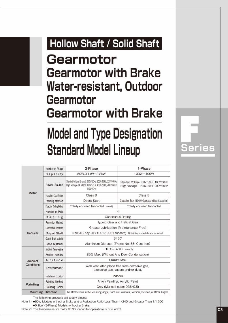
The following products are totally closed.●50W Models without a Brake and a Reduction Ratio Less Than 1/240 and Greater Than 1/1200●0.1kW (3-Phase) Models without a BrakeThe temperature for motor S100 (capacitor operation) is 0 to 40ºC
3-Phase50W,0.1kWー2.2kW
Class B
Direct Start
Totally enclosed fan-cooled Note1)
4
Continuous Rating
Hypoid Gear and Helical Gear
Grease Lubrication (Maintenance Free)
New JIS Key (JIS 1301-1996 Standard) Note) Key materials are included.
S43C
Aluminium Die-cast (Frame No. 55: Cast Iron)
-10℃‒+40℃ Note 2)
85% Max. (Without Any Dew Condensation)
1,000m Max.
Indoors
Anion Painting, Acrylic Paint
Grey (Munsell code: 9B6/0.5)
No Restrictions in the Mounting Angle, Such as Horizontal, Vertical, Inclined, or Other Angles
100Wー400W
Class B
Capacitor Start (100W Operates with a Capacitor)
Totally enclosed fan-cooled
1-Phase
Motor
Reducer
Ambient Conditions
Painting
Mounting Direction
Number of Phase
C a p a c i t y
Power Source
Insulation Classification
Starting Method
Protective Cooling Method
Number of Pole
R a t i n g
Reduction Method
Lubrication Method
Output Shaft
Output Shaft Material
Case Material
Ambient Temperature
Ambient Humidity
A l t i t u d e
Installation Location
Painting Method
Painting Color
Environment Well ventilated place free from corrosive gas, explosive gas, vapors and/or dust.
Standard Voltage (3 rated)High Voltage (4 rated)
200V/50Hz, 200V/60Hz, 220V/60Hz380V/50Hz, 400V/50Hz, 400V/60Hz, 440V/60Hz
Standard VoltageHigh Voltage
100V/50Hz, 100V/60Hz200V/50Hz, 200V/60Hz

C4
50Wー0.4kW
F series 50W‒0.4kW gearmotors and gearmotors with a brake are classified by codes as shown below. Specify these codes in your inquiry and order.
Series
F
F
F①
S
F
S
Mount
②
25
32
45
FrameNumber
④
R
ShaftLocation
⑤
80
120
600
ReductionRatio
⑥
M
MN
W
Motor Type
③
T010
T040
T020
Motor Capacity
⑦ ⑧
W
P
Option
⑨
A
Z
E
Terminal Box
⑩X
Auxiliary Mark
⑪AB
Spec. Designation
①Series Name
②Classification by Mount Form
③Classification by Motor Type
④Frame No. and Diameter of Output Shaft
⑤Output Shaft Placement Marks
⑥Reduction Ratio
⑦Motor Capacity
⑩Auxiliary Mark
⑪Spec. Designation
F
T50T010T020T040S100 200 400
5 : 1/5 - 1500 : 1/1500
Diameter of Output Shaft (Inner diameter is used for Hollow Shaft Type and outer diameter for Solid Shaft Type)
MMNJWVGH
FS
A
P
W
Blank
WZ
Z
PA
WA
BlankX
: F Series(Hollow Shaft, Solid Shaft)
: 3-Phase 50W: 3-Phase 0.1kW: 3-Phase 0.2kW: 3-Phase 0.4kW: 1-Phase 100W (Capacitor Operation): 1-Phase 200W (Capacitor Operation): 1-Phase 400W (Capacitor Operation)
: Without Brake: With Brake: With Brake Manual Release Device (Option) (Note) Excluding 50W: With Water-resistant Motor (Output Shaft Material SUS420J2) IP65: With Water-resistant Brake (Output Shaft Material SUS420J2) IP65: With Outdoor Motor (Output Shaft Material S43C) IP65: With Outdoor Brake Motor (Output Shaft Material S43C) IP65
: Hollow Shaft: Solid Shaft
: Standard Voltage with A-Type Terminal Box
: High Voltage Without Terminal Box For 400V Brake Specifications
: High Voltage Without Terminal Box
: Standard Voltage Without Terminal Box
: High Voltage With Z Model Terminal Box (For Use with Models with a Brake Built-in Rectifier Type)
: Standard Voltage With Z Model Terminal Box (For Use with Models with a Brake Built-in Rectifier Type)
: High Voltage with A-Type Terminal Box for 400V Brake Specification
: High Voltage with A-Type Terminal Box3-Phase :200V/50Hz, 200V/60Hz, 220V/60Hz
E : Standard Voltage with E-Type Terminal Box3-Phase :200V/50Hz, 200V/60Hz, 220V/60Hz
3-Phase :380V/50Hz, 400V/50Hz, 400V/60Hz, 440V/60Hz
Terminal Box Positioning Mark Please refer to the list of specification marks on 〈page E40-E51〉 for details.
200V/50Hz, 200V/60Hz1-Phase :
WE : High Voltage with E-Type Terminal Box3-Phase :380V/50Hz, 400V/50Hz, 400V/60Hz,
440V/60Hz
3-Phase :380V/50Hz, 400V/50Hz, 400V/60Hz, 440V/60Hz
3-Phase :200V/50Hz, 200V/60Hz, 220V/60Hz
3-Phase :380V/50Hz, 400V/50Hz, 400V/60Hz, 440V/60Hz
3-Phase :200V/50Hz, 200V/60Hz, 220V/60Hz
1-Phase :100V/50Hz, 100V/60Hz
1-Phase :100V/50Hz, 100V/60Hz
3-Phase :200V/50Hz, 200V/60Hz, 220V/60Hz
3-Phase :380V/50Hz, 400V/50Hz, 400V/60Hz, 440V/60Hz
(Note) High Voltage with 200V brake specifications is "WA".
(Note) High Voltage with 200V brake specifications is "W".
: Standard Specifications: Mark for Special Additional Specs.
Model and Type Designation F Series
Model andType Designation
Hollow Shaft Solid Shaft
Blank L R T
With the output shaft protruding from the right when looking from the input shaft side ( )
With the output shaft protruding from the left when looking from the input shaft side ( )
With the output shafts protruding from both sides when looking from the input shaft side ( )
Gear Head
Motor
Note 3)If using an inverter, be sure to specify "AC Switching (A)" when placing an order.
*Excluding 50W PE : High Voltage with E-Type Terminal Box for 400V Brake Specification3-Phase :380V/50Hz, 400V/50Hz, 400V/60Hz, 440V/60Hz(Note) High Voltage with 200V brake specifications is "WE".
*Excluding 50W
*Excluding 50W
⑧⑨Options・Power Supply Voltage(* Please inquire regarding other voltages/frequencies.)
・Terminal Box Please specify A or Z for indoor specifications.
Indoor Specification Water-resistant, Outdoor Specification
Note 3)When an inverter is used, always provide instructions for "AC Switching (A)" (custom specification) when submitting an order.An inverter cannot be used with "AC Switching (B)" and "DC Switching".Refer to 〈pages E26, E27 and E52〉 for more information.This option is only available with 200V brake specifications.The option is not available on 400V brake specifications.
FS Type (Hollow Shaft)FF Type (Solid Shaft)
Only hollow shafts are available for Water-resistant and Outdoor Types.
Note)
A-Type Terminal Box is standard for 3-phase.Always add ""A"" as the suffix to the model.When the field is blank, there is no terminal box (lead type).Refer to the following pages for terminal box specifications.• Without Brake: Page E19• With Brake Motor: Page 25• Built-in Rectifier: Page E26-E30
Note 1)
1-phase with a terminal box can be acquired through special order.Refer to 〈pages E25〉 for more information.
Note 2) Note 3)If using an inverter, be sure to specify "AC Switching (A)" when placing an order.

C5
Model andType Designation
0.75kWー2.2kW IE3 (Premium Efficiency)F series 0.75kW‒2.2kW gearmotors and gearmotors with a brake are classified by codes as shown below. Specify these codes in your inquiry and order.
①Series Name
②Classification by Mount Form
⑥Classification by Motor Type
⑦Motor Specs.
③Frame No. and Diameter of Output Shaft
④Output Shaft Material
⑤Reduction Ratio
⑧Motor Capacity
⑨Number of Phase
⑩Power Supply Voltage
⑪Standard
⑫Terminal Box
⑬Brake Specs.
⑭Auxiliary Mark
⑮Spec. Designation
F
Terminal Box Positioning Mark Please refer to the list of specification marks on 〈page E40-E51〉 for details.
Built-in Rectifier Hardwiring Indication Mark Please refer to the list of specification marks on 〈page E28-E29〉 for details.
BlankX
NB2B4V2V4J2J4
TE
N
NW
T
081522
P
MW
5 : 1/5 - 450 : 1/450
Diameter of Output Shaft (Inner diameter is used for Hollow Shaft Type and outer diameter for Solid Shaft Type)
SF
: F Series (Hollow Shaft, Solid Shaft)
: Standard Specifications: Mark for Special Additional Specs
: Without Brake: 200V Brake Specification: 400V Brake Specification: Water-resistant 200V Brake Specification: Water-resistant 400V Brake Specification: With Brake Manual Release Device(Option) 200V Brake Specification: With Brake Manual Release Device(Option) 400V Brake Specification
: T Model Terminal Box(Steel Plate): T Model Terminal Box(Aluminium)
: For Japan and Europe(CE Marking)
: Standard Voltage : High Voltage
: 3-Phase
: 3-Phase 0.75kW: 3-Phase 1.5kW: 3-Phase 2.2kW
: IE3 Efficiency 〈Premium Efficiency〉
: Induction Standard Motor (IP44): Induction Water-resistant Motor (IP65)
: Hollow Shaft: Solid Shaft
For models with a brake, the brake lead wire is housed inside the terminal Box. Please refer to 〈page E25〉.
3-Phase 3Rated 200V/50Hz, 200V/60Hz, 220V/60Hz3-Phase 3Rated 380V/50Hz, 400V/50Hz, 400V/60Hz, 440V/60Hz
Gear Head Type
Series
F
F
F
①
S
F
S
Mount
②
45
40
55
FrameNumber
③
N
T
S
ShaftLocation
④
5
100
25
ReductionRatio
⑤
BrakeSpecs.
⑬
N
B4
N
Brake
Option
⑭
X
X
AuxiliaryMark
⑮
AA
T9HZ
Spec.Designation
⑫
T
T
E
TerminalBox
⑥
M
M
W
MotorType
⑦
P
P
P
MotorSpecs.
⑧
08
08
22
Capacity
⑨
T
T
T
Number ofPhase
⑩
N
W
N
Power SupplyVoltage
⑪
N
N
N
Standard
Motor Model
Solid ShaftShaft Material Hollow Shaft
S43C N
SUS420J2 SL R
─T
With the output shaft protruding from the left when looking from the input shaft side ( )
With the output shaft protruding from the right when looking from the input shaft side ( )
With the output shafts protruding from both sides when looking from the input shaft side ( )
Note) There are no 1.5kW or 2.2kW gearmotors with a brake.
C6
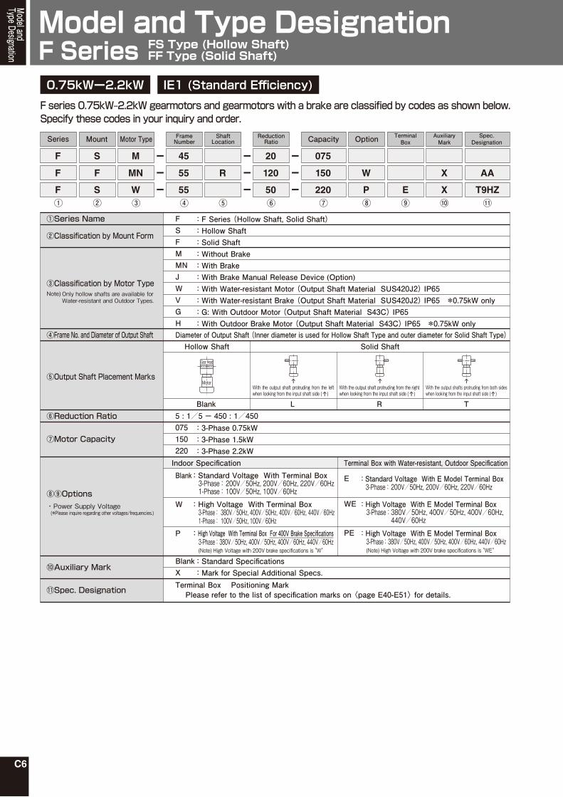
F series 0.75kW‒2.2kW gearmotors and gearmotors with a brake are classified by codes as shown below. Specify these codes in your inquiry and order.
Series
F
F
F①
S
F
S
Mount
②
45
55
55
FrameNumber
④
R
ShaftLocation
⑤
20
120
50
ReductionRatio
⑥
M
MN
W
Motor Type
③
075
150
220
Capacity
⑦ ⑧
W
P
Option
⑨E
TerminalBox
⑩X
X
AuxiliaryMark
⑪T9HZ
AA
Spec.Designation
①Series Name
②Classification by Mount Form
③Classification by Motor Type
④Frame No. and Diameter of Output Shaft
⑤Output Shaft Placement Marks
⑥Reduction Ratio
⑦Motor Capacity
⑩Auxiliary Mark
⑪Spec. Designation
F
075150220
5 : 1/5 - 450 : 1/450
Diameter of Output Shaft (Inner diameter is used for Hollow Shaft Type and outer diameter for Solid Shaft Type)
MMNJWVGH
FS
BlankX
Blank
W
P
: F Series (Hollow Shaft, Solid Shaft)
: 3-Phase 0.75kW: 3-Phase 1.5kW: 3-Phase 2.2kW
: Without Brake: With Brake: With Brake Manual Release Device (Option): With Water-resistant Motor (Output Shaft Material SUS420J2) IP65: With Water-resistant Brake (Output Shaft Material SUS420J2) IP65 *0.75kW only: G: With Outdoor Motor (Output Shaft Material S43C) IP65: With Outdoor Brake Motor (Output Shaft Material S43C) IP65 *0.75kW only
: Hollow Shaft: Solid Shaft
E : Standard Voltage With E Model Terminal Box3-Phase :200V/50Hz, 200V/60Hz, 220V/60Hz
Only hollow shafts are available for Water-resistant and Outdoor Types.
Note)
Terminal Box Positioning Mark Please refer to the list of specification marks on 〈page E40-E51〉 for details.
WE : High Voltage With E Model Terminal Box3-Phase :380V/50Hz, 400V/50Hz, 400V/60Hz,
440V/60Hz
: Standard Specifications: Mark for Special Additional Specs.
Model and Type Designation F Series
Model andType Designation
Hollow Shaft Solid Shaft
Blank L R T
0.75kWー2.2kW IE1 (Standard Efficiency)
Gear Head
Motor
PE : High Voltage With E Model Terminal Box3-Phase :380V/50Hz, 400V/50Hz, 400V/60Hz, 440V/60Hz(Note) High Voltage with 200V brake specifications is "WE"
Indoor Specification Terminal Box with Water-resistant, Outdoor Specification
: High Voltage With Terminal Box For 400V Brake Specifications
: High Voltage With Terminal Box
: Standard Voltage With Terminal Box3-Phase :200V/50Hz, 200V/60Hz, 220V/60Hz
1-Phase : 100V/50Hz, 100V/60Hz
1-Phase :100V/50Hz, 100V/60Hz
3-Phase : 380V/50Hz, 400V/50Hz, 400V/60Hz, 440V/60Hz
3-Phase :380V/50Hz, 400V/50Hz, 400V/60Hz, 440V/60Hz(Note) High Voltage with 200V brake specifications is "W"
FS Type (Hollow Shaft)FF Type (Solid Shaft)
With the output shaft protruding from the left when looking from the input shaft side ( )
With the output shaft protruding from the right when looking from the input shaft side ( )
With the output shafts protruding from both sides when looking from the input shaft side ( )
⑧⑨Options・Power Supply Voltage (*Please inquire regarding other voltages/frequencies.)

C7
Model andType Designation

C8
Gearmotor
Gearmotor with Brake
Gearmotor Equipped with Brake Manual Release Device
Note 2)
Type 4P Motor Capacity
FrameNumber Reduction Ratio
20
35
30
25
25
30
35
3-Phase 50W
3-Phase 0.1kW
1-Phase 100W
3-Phase 0.2kW
1-Phase 200W
3-Phase 0.4kW
1-Phase 400W
3-Phase 0.75kW
3-Phase 1.5kW
3-Phase 2.2kW
1/10 1/12.5 1/15 1/20 1/25 1/30 1/40 1/50 1/60
1/80 1/100 1/120 1/160 1/200 1/240
1/300 1/375 1/450
1/600 1/750 1/900
1/10 1/12.5 1/15 1/20 1/25 1/30 1/40 1/50 1/60
1/80 1/100 1/120 1/160 1/200
1/1200 1/1500
1/240
1/300 1/375 1/450
1/600 1/750 1/900
1/5 1/7.5 1/10 1/12.5 1/15 1/20 1/25 1/30
1/200 1/240
1/40
1/50 1/60 1/80 1/100 1/120
1/1200 1/1500
1/160
1/300 1/375 1/450
1/600 1/750 1/900
1/5 1/7.5 1/10 1/12.5 1/15 1/20 1/25 1/30
1/200 1/240
1/40
1/50 1/60 1/80 1/100 1/120
1/1200 1/1500
1/160
1/300 1/375 1/450
1/300 1/375 1/450
1/600 1/750 1/900
1/1200 1/1500 1/1800
30
35
45
35
45
55
45
55
55
55
1/5 1/7.5 1/10 1/12.5 1/15 1/20 1/25 1/30 1/40
1/120 1/160 1/200 1/2401/50 1/60 1/80 1/100
1/5 1/7.5 1/10 1/12.5 1/15 1/20 1/25 1/30 1/40
1/120 1/160 1/200 1/2401/50 1/60 1/80 1/100
1/5 1/7.5 1/10 1/12.5 1/15 1/20 1/25 1/30 1/40
1/1201/50 1/60 1/80 1/100
Standard ModelLineup Standard Model LineupF Series FS Type(Hollow Shaft)
There are no gearmotors with a manual brake release for 3-phase 50W models.There are no 1-phase 100W models with a high reduction ratio (1/300 or greater).The models enclosed with " " are the low torque type. Special care should be given to the allowable torque in the performance table.
Note 1)2)3)
Note 1)
Indoor Type
FS Type (Hollow Shaft) Model Lineup

C9
Standard Model LineupStandard ModelLineup
防水型
Water-resistant Gearmotor
Outdoor Gearmotor
Type 4P Motor Capacity
FrameNumber Reduction Ratio
25
30
35
3-Phase 0.1kW
3-Phase 0.2kW
3-Phase 0.4kW
3-Phase 0.75kW
3-Phase 1.5kW
3-Phase 2.2kW
1/10 1/12.5 1/15 1/20 1/25 1/30 1/40 1/50 1/60
1/80 1/100 1/120 1/160 1/200
1/1200 1/1500
1/240
1/300 1/375 1/450
1/600 1/750 1/900
1/5 1/7.5 1/10 1/12.5 1/15 1/20 1/25 1/30
1/200 1/240
1/40
1/50 1/60 1/80 1/100 1/120
1/1200 1/1500
1/160
1/300 1/375 1/450
1/600 1/750 1/900
1/5 1/7.5 1/10 1/12.5 1/15 1/20 1/25 1/30
1/200 1/240
1/40
1/50 1/60 1/80 1/100 1/120
1/1200 1/1500
1/160
1/300 1/375 1/450
1/300 1/375 1/450
1/600 1/750 1/900
30
35
45
35
45
55
45
55
55
55
1/5 1/7.5 1/10 1/12.5 1/15 1/20 1/25 1/30 1/40
1/120 1/160 1/200 1/2401/50 1/60 1/80 1/100
1/5 1/7.5 1/10 1/12.5 1/15 1/20 1/25 1/30 1/40
1/120 1/160 1/200 1/2401/50 1/60 1/80 1/100
1/5 1/7.5 1/10 1/12.5 1/15 1/20 1/25 1/30 1/40
1/1201/50 1/60 1/80 1/100
Water-resistant Type
FS Type (Hollow Shaft) Model Lineup
Water-resistant Gearmotor with
Brake
Outdoor Gearmotor with
Brake
Water-resistant Gearmotor
Water-resistant Gearmotor with
Brake
Water-resistant Gearmotor
The models enclosed with " " are the low torque type. Special care should be given to the allowable torque in the performance table.
Note 1)

C10
Type 4P Motor Capacity
Output Shaft Positioning
FrameNumber Reduction Ratio
1/10 1/12.5 1/15 1/20 1/25 1/30 1/40 1/50 1/60
1/80 1/100 1/120 1/160 1/200 1/240
1/10 1/12.5 1/15 1/20 1/25 1/30 1/40 1/50 1/60
1/80 1/100 1/120 1/160 1/200 1/240
1/5 1/7.5 1/10 1/12.5 1/15 1/20 1/25 1/30 1/40
1/120 1/160 1/200 1/2401/50 1/60 1/80 1/100
1/5 1/7.5 1/10 1/12.5 1/15 1/20 1/25 1/30 1/40
1/120 1/160 1/200 1/2401/50 1/60 1/80 1/100
1/5 1/7.5 1/10 1/12.5 1/15 1/20 1/25 1/30 1/40
1/120 1/160 1/200 1/2401/50 1/60 1/80 1/100
183-Phase 50W
3-Phase 0.1kWGearmotor
Gearmotor with Brake
Gearmotor Equipped with Brake Manual Release Device
22
RT
L
RT
L
3-Phase 0.2kW 28 RT
L
3-Phase 0.4kW 32 RT
L
3-Phase 0.75kW 40 RT
L
Standard ModelLineup Standard Model LineupF Series FF Type(Solid Shaft)
Note 1)
Indoor Type
FF Type (Solid Shaft) Model Lineup
There are no gearmotors with a manual brake release for 3-phase 50W models.The models enclosed with " " are the low torque type. Special care should be given to the allowable torque in the performance table.
Note 1)2)

C11
Standard ModelLineup

C12

FSeries
FSType
TypeFF
C13
●Values in the parenthesis in the performance table / dimension diagram are the values of gearmotor with brake.●The output shaft rotation speed is the value corresponding to the motor synchronous speed and the nominal reduction ratio.●The key for the outout shaft is not attached to this model.●For hollow shafts highlighted by in the performance table with wiring (normal rotation) shown on 〈page E18,E34〉, the rotation is to the right when looking from the flange surface. (Refer to the diagram below)●For solid shafts highlighted by in the performance table with wiring (normal shaft) shown on 〈page E18,E34〉, the L-shaft, when looking from the direction of the output shaft, rotates to the right, and the R- and T-shafts rotate to the left. (Refer to the diagram below)
【Remarks】
Performance Table / Dimension Diagram
GearmotorGearmotor with BrakeWater-resistant, OutdoorGearmotorGearmotor with Brake
Hollow Shaft/Solid Shaft
L Shaft R Shaft T Shaft
3-Phase

C14
50W-0.4kW
CapacityMotor
Specification
PowerSupply
V Hz A r/min 50Hz 60Hz 50Hz 60Hz 50Hz 60Hz
Indoor TypeWater-resistant Type
Frequency RatedCurrent Frame
NumberReductionRatio
ActualReductionRatio
Note 1)2)3)
The allowable O.H.L. are the values measured at the position of 20mm from the edge of output shaft.Please be sure to read the remarks stated on 〈page C13〉 regarding the rotation method of output shaft.The models marked with * are limited torque type. Be sure to refer to the allowable torque in the performance table.
Output ShaftRotation Speed
Output ShaftAllowable Torque
Output ShaftAllowable O.H.L.
Outer Dimension Diagram
r/min N・m Kgf・m N Kgf
RatedRotationSpeed
1/18001/15001/12001/9001/7501/6001/4501/3751/300*1/2401/2001/1601/1201/1001/801/601/501/401/301/251/201/151/12.51/10
*1/1500*1/12001/9001/7501/6001/4501/3751/300*1/240*1/2001/1601/1201/1001/801/601/501/401/301/251/201/151/12.51/10
*1/1500*1/1200*1/9001/7501/600*1/4501/3751/300*1/240*1/2001/1601/1201/1001/801/601/501/401/301/251/201/151/12.51/101/7.51/5
*1/1500*1/1200*1/900*1/7501/600*1/4501/3751/300*1/240*1/200*1/1601/1201/1001/801/601/501/401/301/251/201/151/12.51/101/7.51/5
1/180019/282001/12001/90019/141001/6001/4501/3751/30010/24191/2051/1641/1232/2051/8240/24194/2051/414/1238/2052/418/123100/12714/417/106007/84807/6360133/996407/42407/3060133/479407/20401/2401/2001/1601/12019/18801/801/601/501/401/3019/4701/201/152/251/107/106007/84807/6360133/996407/42407/3180133/498207/21201/2401/2001/1601/12019/18801/801/601/501/401/301/251/201/1519/2351/102/151/5
11/1664049/572007/613611/832049/286007/3120133/488807/20801/2401/2001/1601/12019/18801/801/601/501/401/301/251/201/1519/2351/102/151/5
0.811.31.722.53.3456.37.59.412.51518.8253037.550607510012015011.31.722.53.3456.37.59.412.51518.8253037.550607510012015011.31.722.53.3456.37.59.412.51518.8253037.550607510012015020030011.31.722.53.3456.37.59.412.51518.8253037.5506075100120150200300
11.21.522.4344.867.59
11.3151822.53036456072901201441801.21.522.4344.867.59
11.3151822.53036456072901201441801.21.522.4344.867.59
11.3151822.53036456072901201441802403601.21.522.4344.867.59
11.3151822.5303645607290120144180240360
3723112481861551249982665449392925201613117.76.55.23.83.22.537237237231124819816513110198785949393125211613117.76.55.2713713713668534372353282184184169126105846755443327231714118.35.5
10301030103010301030713707565270270270253211169133111886755443327231711
31125920715512910482695549413225211713118.66.55.44.33.22.62.237237231125920716513711098816649413225221813118.66.55.44.3713713668557446353294235184175140105877155463727241914129.274.6
10301030103010308917075894712702702702111751401119274554637272419149.2
3831.725.31915.812.710.18.46.75.55432.521.61.31.10.790.660.530.390.330.2638383831.725.320.216.813.410.31086543.22.62.11.61.31.10.790.660.5372.872.872.868.254.5383628.818.818.817.212.910.78.66.85.64.53.42.82.31.71.41.10.850.5610510510510510572.872.157.727.627.627.625.821.517.213.611.396.85.64.53.42.82.31.71.1
31.726.421.115.813.210.68.475.654.23.32.52.11.71.31.10.880.660.550.440.330.270.22383831.726.421.116.81411.2108.36.754.23.32.62.21.81.31.10.880.660.550.4472.872.868.256.845.536302418.817.914.310.78.97.25.64.73.82.82.41.91.41.20.940.710.4710510510510590.972.160.148.127.627.627.621.517.914.311.39.47.55.64.73.82.82.41.91.40.94
3630363036303140314031402550255025501860186018601860186018601860186018101670157014701320127011803630363036303630363031403140314025502550255025502550255025502450230021102010186017201620152051905190519051905190363036303630314031403140314031403090309029902840265025502400216020601910176015209800980098009800980051905190519036303630363035303530348034803480348032803190299027402600245022501960
37037037032032032026026026019019019019019019019019018517016015013513012037037037037037032032032026026026026026026026025023521520519017516515553053053053053037037037032032032032032031531530529027026024522021019518015510001000100010001000530530530370370370360360355355355355355325305280265250230200
P.C22P.C27
P.C21P.C26
P.C20P.C26
P.C20─
P.C22P.C27
P.C21P.C26
P.C20P.C26
P.C23P.C28
P.C22P.C27
P.C21P.C26
P.C24P.C29
P.C23P.C28
P.C22P.C27
35
30
25
135015501600
0.400.360.36
506060
200200220
135015501550
0.420.390.39
506060
200200220
135015501600
0.400.360.36
506060
200200220
142017001720
0.610.540.54
506060
200200220
3-Phase50W
3-Phase0.1kW
142017001720
1.11.01.0
506060
200200220
3-Phase0.2kW
141016901710
2.11.81.8
506060
200200220
3-Phase0.4kW
20
35
30
25
45
35
30
55
45
35
Output ShaftAllowableThrust Load
N Kgf
9129129127857857856376376374714714714714714714714714514223923733333242949129129129129127857857856376376376376376376376185795305004714314023821275127512751275127591291291278578578578578577577574571666763759853952048144138224522452245224522452127512751275912912912883883873873873873824794745686647618569490
939393808080656565484848484848484846434038343330939393939380808065656565656565635954514844413913013013013013093939380808080807979767368656155534945392502502502502501301301309393939090898989898481767066635850
Standard ModelLineup
Gearmotor / Gearmotor with Brake 3-Phase Performance TableHollow Shaft F Series (FS Type)
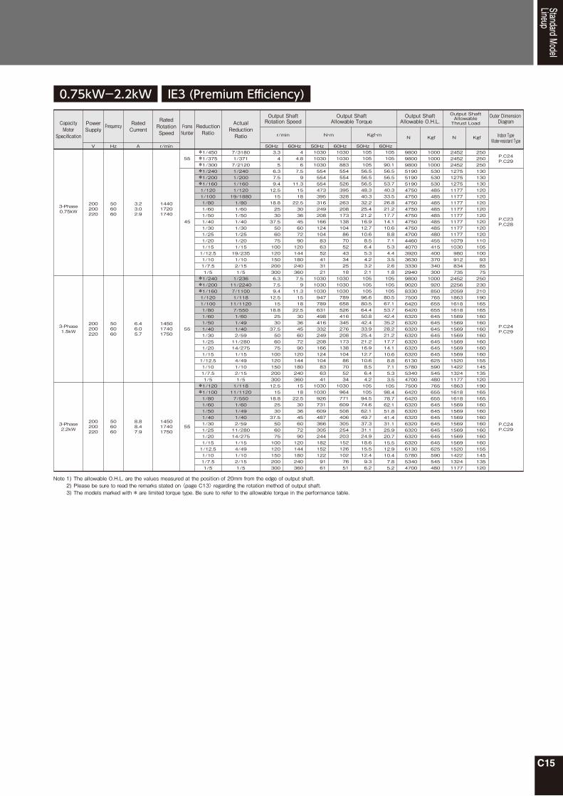
C15
0.75kW-2.2kW
*1/450*1/375*1/300*1/240*1/200*1/1601/1201/1001/801/601/501/401/301/251/201/151/12.51/101/7.51/5
*1/240*1/200*1/1601/1201/1001/801/601/501/401/301/251/201/151/12.51/101/7.51/5
*1/120*1/1001/801/601/501/401/301/251/201/151/12.51/101/7.51/5
7/31801/3717/21201/2401/2001/1601/12019/18801/801/601/501/401/301/251/201/1519/2351/102/151/51/23611/22407/11001/11811/11207/5501/601/491/402/5911/28014/2751/154/491/102/151/51/11811/11207/5501/601/491/402/5911/28014/2751/154/491/102/151/5
3.3456.37.59.412.51518.8253037.55060751001201502003006.37.59.412.51518.8253037.550607510012015020030012.51518.8253037.5506075100120150200300
44.867.59
11.3151822.53036456072901201441802403607.59
11.3151822.5303645607290120144180240360151822.5303645607290120144180240360
103010301030554554554473395316249208166124104836352413121
103010301030947789631498416332249208166124104836341
103010309267316094873663052441821521229161
1030103088355455452639532826320817313810486705243342518
10301030103078965852641634527620817313810486705234
10309647716095084063052542031521261027651
10510510556.556.556.548.340.332.225.421.216.912.710.68.56.45.34.23.22.110510510596.680.564.450.842.433.925.421.216.912.710.68.56.44.210510594.574.662.149.737.331.124.918.615.512.49.36.2
10510590.156.556.553.740.333.526.821.217.714.110.68.87.15.34.43.52.61.810510510580.567.153.742.435.228.221.217.714.110.68.87.15.33.510598.478.762.151.841.431.125.920.715.512.910.47.85.2
980098009800519051905190475047504750475047504750475047004460407039203630333029409800902083307500642064206320632063206320632063206320613057805340470075006420642063206320632063206320632063206130578053404700
1000100010005305305304854854854854854854854804554154003703403001000920850765655655645645645645645645645625590545480765655655645645645645645645645625590545480
P.C24P.C29
P.C23P.C28
P.C24P.C29
P.C24P.C29
55
144017201740
3.23.02.9
506060
200200220
145017401750
6.46.05.7
506060
200200220
3-Phase0.75kW
3-Phase1.5kW
145017401750
8.88.47.9
506060
200200220
3-Phase2.2kW
45
55
55
24522452245212751275127511771177117711771177117711771177107910309809128347352452225620591863161816181569156915691569156915691569152014221324117718631618161815691569156915691569156915691520142213241177
250250250130130130120120120120120120120120110105100938575250230210190165165160160160160160160160155145135120190165165160160160160160160160155145135120
Standard ModelLineup
Note 1)2)3)
The allowable O.H.L. are the values measured at the position of 20mm from the edge of output shaft.Please be sure to read the remarks stated on 〈page C13〉 regarding the rotation method of output shaft.The models marked with * are limited torque type. Be sure to refer to the allowable torque in the performance table.
CapacityMotor
Specification
PowerSupply
V Hz A r/min 50Hz 60Hz 50Hz 60Hz 50Hz 60Hz
Indoor TypeWater-resistant Type
Frequency RatedCurrent Frame
NumberReductionRatio
ActualReductionRatio
Output ShaftRotation Speed
Output ShaftAllowable Torque
Output ShaftAllowable O.H.L.
Outer Dimension Diagram
r/min N・m Kgf・m N Kgf
RatedRotationSpeed
Output ShaftAllowableThrust Load
N Kgf
IE3 (Premium Efficiency)

C16
0.75kW-2.2kW IE1 (Standard Efficiency)
*1/450*1/375*1/300*1/240*1/200*1/1601/1201/1001/801/601/501/401/301/251/201/151/12.51/101/7.51/5
*1/240*1/200*1/1601/1201/1001/801/601/501/401/301/251/201/151/12.51/101/7.51/5
*1/120*1/1001/801/601/501/401/301/251/201/151/12.51/101/7.51/5
7/31801/3717/21201/2401/2001/1601/12019/18801/801/601/501/401/301/251/201/1519/2351/102/151/51/23611/22407/11001/11811/11207/5501/601/491/402/5911/28014/2751/154/491/102/151/51/11811/11207/5501/601/491/402/5911/28014/2751/154/491/102/151/5
3.3456.37.59.412.51518.8253037.55060751001201502003006.37.59.412.51518.8253037.550607510012015020030012.51518.8253037.5506075100120150200300
44.867.59
11.3151822.53036456072901201441802403607.59
11.3151822.5303645607290120144180240360151822.5303645607290120144180240360
103010301030554554554473395316249208166124104836352413121
103010301030947789631498416332249208166124104836341
103010309267316094873663052441821521229161
1030103088355455452639532826320817313810486705243342518
10301030103078965852641634527620817313810486705234
10309647716095084063052542031521261027651
10510510556.556.556.548.340.332.225.421.216.912.710.68.56.45.34.23.22.110510510596.680.564.450.842.433.925.421.216.912.710.68.56.44.210510594.574.662.149.737.331.124.918.615.512.49.36.2
10510590.156.556.553.740.333.526.821.217.714.110.68.87.15.34.43.52.61.810510510580.567.15342.435.228.221.217.714.110.68.87.15.33.510598.478.762.151.841.431.125.920.715.512.910.47.85.2
980098009800519051905190475047504750475047504750475047004460407039203630333029409800902083307500642064206320632063206320632063206320613057805340470075006420642063206320632063206320632063206130578053404700
1000100010005305305304854854854854854854854804554154003703403001000920850765655655645645645645645645645625590545480765655655645645645645645645645625590545480
P.C24P.C29
P.C23P.C28
P.C24P.C29
P.C24P.C29
55
143017201730
3.73.33.2
506060
200200220
143017201730
6.66.15.8
506060
200200220
3-Phase0.75kW
3-Phase1.5kW
141016901710
9.08.68.0
506060
200200220
3-Phase2.2kW
45
55
55
24522452245212751275127511771177117711771177117711771177107910309809128347352452225620591863161816181569156915691569156915691569152014221324117718631618161815691569156915691569156915691520142213241177
250250250130130130120120120120120120120120110105100938575250230210190165165160160160160160160160155145135120190165165160160160160160160160155145135120
Standard ModelLineup
Gearmotor / Gearmotor with Brake 3-Phase Performance TableHollow Shaft F Series (FS Type)
CapacityMotor
Specification
PowerSupply
V Hz A r/min 50Hz 60Hz 50Hz 60Hz 50Hz 60Hz
Indoor TypeWater-resistant Type
Frequency RatedCurrent Frame
NumberReductionRatio
ActualReductionRatio
Output ShaftRotation Speed
Output ShaftAllowable Torque
Output ShaftAllowable O.H.L.
Outer Dimension Diagram
r/min N・m Kgf・m N Kgf
RatedRotationSpeed
Output ShaftAllowableThrust Load
N Kgf
Note 1)2)3)
The allowable O.H.L. are the values measured at the position of 20mm from the edge of output shaft.Please be sure to read the remarks stated on 〈page C13〉 regarding the rotation method of output shaft.The models marked with * are limited torque type. Be sure to refer to the allowable torque in the performance table.

C17
Standard ModelLineup
C18
50W-0.4kW
*1/2401/2001/1601/1201/1001/801/601/501/401/301/251/201/151/12.51/10*1/2401/2001/1601/1201/1001/801/601/501/401/301/251/201/151/12.51/10*1/240*1/2001/1601/1201/1001/801/601/501/401/301/251/201/151/12.51/101/7.51/5
*1/240*1/200*1/1601/1201/1001/801/601/501/401/301/251/201/151/12.51/101/7.51/5
10/24191/2051/1641/1232/2051/8240/24194/2051/414/1238/2052/418/123100/12714/411/2401/2001/1601/12019/18801/801/601/501/401/3019/4701/201/152/251/101/2401/2001/1601/12019/18801/801/601/501/401/301/251/201/1519/2351/102/151/51/2401/2001/1601/12019/18801/801/601/501/401/301/251/201/1519/2351/102/151/5
6.37.59.412.51518.8253037.55060751001201506.37.59.412.51518.8253037.55060751001201506.37.59.412.51518.8253037.55060751001201502003006.37.59.412.51518.8253037.5506075100120150200300
7.59
11.3151822.53036456072901201441807.59
11.3151822.53036456072901201441807.59
11.3151822.53036456072901201441802403607.59
11.3151822.5303645607290120144180240360
5449392925201613117.76.55.23.83.22.510198785949393125211613117.76.55.2184184169126105846755443327231714118.35.5270270270253211169133111886755443327231711
49413225211713118.66.55.44.33.22.62.298816649413225221813118.66.55.44.3184175140105877155463727241914129.274.62702702702111751401119274554637272419149.2
5.55432.521.61.31.10.790.660.530.390.330.2610.31086543.22.62.11.61.31.10.790.660.5318.818.817.212.910.78.66.85.64.53.42.82.31.71.41.10.850.5627.627.627.625.821.517.213.611.396.85.64.53.42.82.31.71.1
54.23.32.52.11.71.31.10.880.660.550.440.330.270.22108.36.754.23.32.62.21.81.31.10.880.660.550.4418.817.914.310.78.97.25.64.73.82.82.41.91.41.20.940.710.4727.627.627.621.517.914.311.39.47.55.64.73.82.82.41.91.40.94
1860186018601860186018601860186017201570147013701230118010802550255025502550255025502550255024002160206019101720162015203140314031403140314030903090299027902600245023002060196018101670147036303630358033803380333033303330328030402890270025002350221020101760
190190190190190190190190175160150140125120110260260260260260260260260245220210195175165155320320320320320315315305285265250235210200185170150370370365345345340340340335310295275255240225205180
P.C30
P.C30
P.C31
P.C31
135015501600
0.400.360.36
506060
200200220
142017001720
0.610.540.54
506060
200200220
3-Phase50W
3-Phase0.1kW
142017001720
1.11.01.0
506060
200200220
3-Phase0.2kW
141016901710
2.11.81.8
506060
200200220
3-Phase0.4kW
18
22
28
32
0.75kW
*1/240*1/200*1/1601/1201/1001/801/601/501/401/301/251/201/151/12.51/101/7.51/5
1/2401/2001/1601/12019/18801/801/601/501/401/301/251/201/1519/2351/102/151/5
6.37.59.412.51518.8253037.5506075100120150200300
7.59
11.3151822.5303645607290120144180240360
554554554473395316249208166124104836352413121
55455452639532826320817313810486705243342518
56.556.556.548.340.332.225.421.216.912.710.68.56.45.34.23.22.1
56.556.553.740.333.526.821.217.714.110.68.87.15.34.43.52.61.8
51905190485044604460446044604460446043104170387035303380314028402500
530530495455455455455455455440425395360345320290255
P.C32144017201740
3.23.02.9
506060
200200220
3-Phase0.75kW 40
Standard ModelLineup
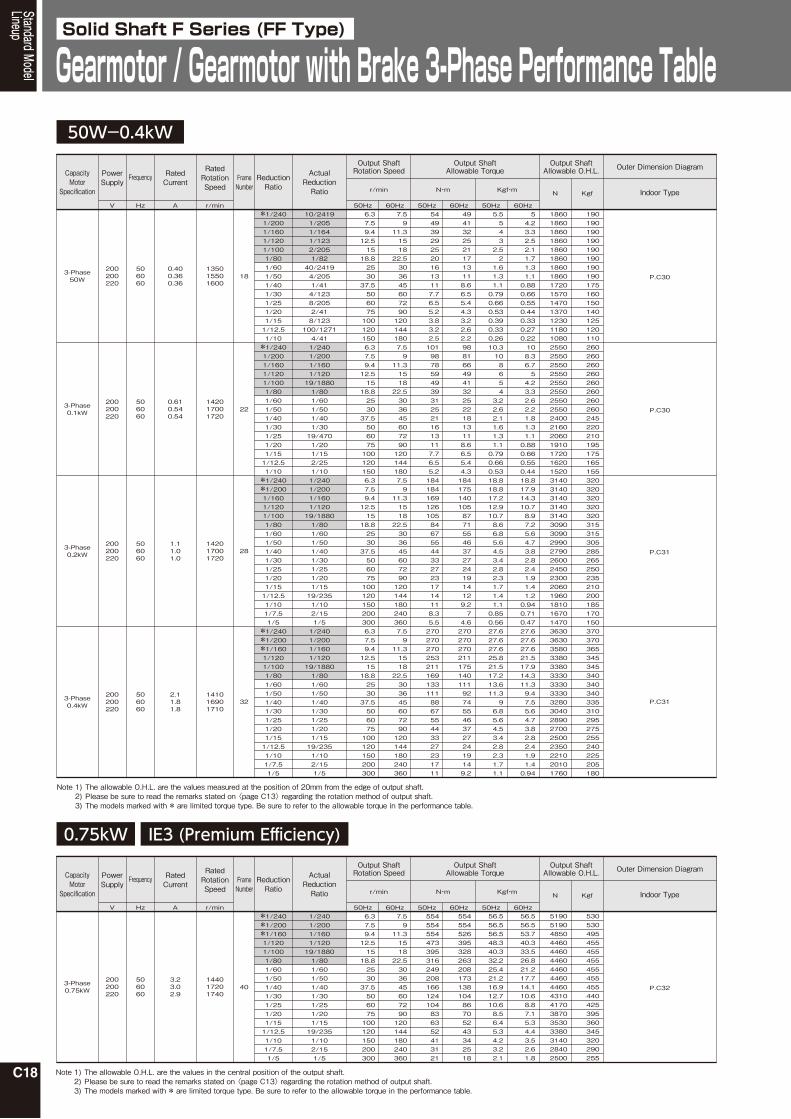
Gearmotor / Gearmotor with Brake 3-Phase Performance TableSolid Shaft F Series (FF Type)
CapacityMotor
Specification
PowerSupply
V Hz A r/min 50Hz 60Hz 50Hz 60Hz 50Hz 60Hz
Indoor Type
Frequency RatedCurrent Frame
NumberReductionRatio
ActualReductionRatio
Output ShaftRotation Speed
Output ShaftAllowable Torque
Output ShaftAllowable O.H.L. Outer Dimension Diagram
r/min N・m Kgf・m N Kgf
RatedRotationSpeed
IE3 (Premium Efficiency)
Note 1)2)3)
The allowable O.H.L. are the values measured at the position of 20mm from the edge of output shaft.Please be sure to read the remarks stated on 〈page C13〉 regarding the rotation method of output shaft.The models marked with * are limited torque type. Be sure to refer to the allowable torque in the performance table.
Note 1)2)3)
The allowable O.H.L. are the values in the central position of the output shaft.Please be sure to read the remarks stated on 〈page C13〉 regarding the rotation method of output shaft.The models marked with * are limited torque type. Be sure to refer to the allowable torque in the performance table.

C19
0.75kW
※1/240※1/200※1/1601/1201/1001/801/601/501/401/301/251/201/151/12.51/101/7.51/5
1/2401/2001/1601/12019/18801/801/601/501/401/301/251/201/1519/2351/102/151/5
6.37.59.412.51518.8253037.5506075100120150200300
7.59
11.3151822.5303645607290120144180240360
554554554473395316249208166124104836352413121
55455452639532826320817313810486705243342518
56.556.556.548.340.332.225.421.216.912.710.68.56.45.34.23.22.1
56.556.553.740.333.526.821.217.714.110.68.87.15.34.43.52.61.8
51905190485044604460446044604460446043104170387035303380314028402500
530530495455455455455455455440425395360345320290255
P.C32143017201730
3.73.33.2
506060
200200220
3-Phase0.75kW 40
Standard ModelLineup
IE1 (Standard Efficiency)
CapacityMotor
Specification
PowerSupply
V Hz A r/min 50Hz 60Hz 50Hz 60Hz 50Hz 60Hz
Indoor Type
Frequency RatedCurrent Frame
NumberReductionRatio
ActualReductionRatio
Output ShaftRotation Speed
Output ShaftAllowable Torque
Output ShaftAllowable O.H.L. Outer Dimension Diagram
r/min N・m Kgf・m N Kgf
RatedRotationSpeed
Note 1)2)3)
The allowable O.H.L. are the values in the central position of the output shaft.Please be sure to read the remarks stated on 〈page C13〉 regarding the rotation method of output shaft.The models marked with * are limited torque type. Be sure to refer to the allowable torque in the performance table.
C20
Outer DimensionDiagrams
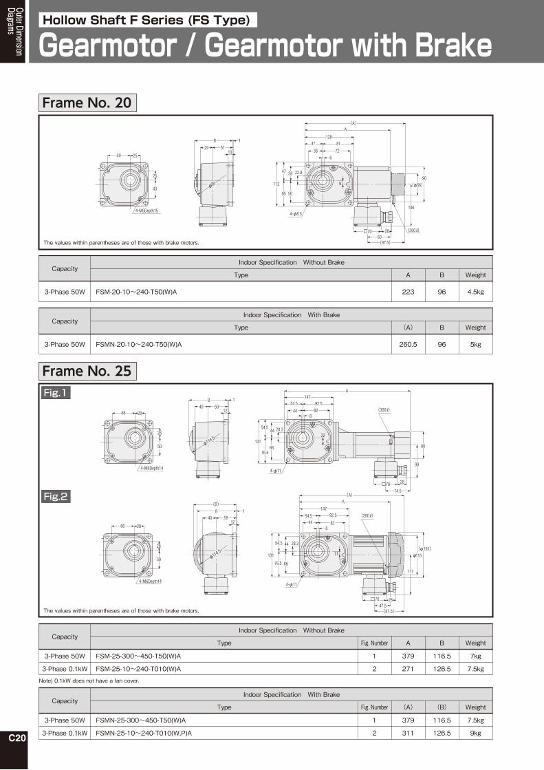
Gearmotor / Gearmotor with BrakeHollow Shaft F Series (FS Type)
Indoor Specification Without Brake
FSM-20-10~240-T50(W)A 223 96 4.5kg3-Phase 50W
CapacityType A B Weight
The values within parentheses are of those with brake motors.
Indoor Specification With Brake
FSMN-20-10~240-T50(W)A 260.5 96 5kg3-Phase 50W
CapacityType (A) B Weight
The values within parentheses are of those with brake motors.
Indoor Specification Without Brake
FSM-25-300~450-T50(W)A
FSM-25-10~240-T010(W)A
379
271
116.5
126.5
7kg
7.5kg
3-Phase 50W
3-Phase 0.1kW
CapacityType A B Weight
Indoor Specification With Brake
FSMN-25-300~450-T50(W)A
FSMN-25-10~240-T010(W,P)A
379
311
116.5
126.5
7.5kg
9kg
3-Phase 50W
3-Phase 0.1kW
CapacityType (A)
1
2
Fig. Number
1
2
Fig. Number (B) Weight
Note) 0.1kW does not have a fan cover.
25
25
43
4-M5Depth15
59
29
φ90
1051
B 1128
106
112
22.8
47
47
4-φ8.5
72
90
2870
9
38
56
38
65
6
81
(300 )
(φ56)
(A)A
(97.5)60
28
28
50
4-M6Depth14
66
B
φ114.5
125940
1
131
147
74.5
54.5
54.5 28.3
76.5
92.5
66
A
4-φ11
80
99
82
44
70
844
22
28
(300 )
28
28
50
4-M6Depth14
66
B
125940
1
131
147
117
47.5
54.5
54.5
28.3
76.5
92.5
66
A
4-φ11
82
44
70
448
11
28
115φ
(200 )
(φ135)
(A)
(B)
φ114.5
(87.5)
Frame No. 20
Frame No. 25Fig.1
Fig.2

C21
Outer DimensionDiagrams
Indoor Specification Without Brake
FSM-30-600~900-T50(W)A
FSM-30-300~450-T010(W)A
FSM-30-5~240-T020(W)A
395
337
333
129
128.5
132.5
─
15.5
11
─
115
135
9kg
11.5kg
9.5kg
3-Phase 50W
3-Phase 0.1kW
3-Phase 0.2kW
CapacityType A B C D
─
─
78.5
E Weight
The values within parentheses are of those with brake motors.
Indoor Specification With Brake
FSMN-30-600~900-T50(W)A
FSMN-30-300~450-T010(W,P)A
FSMN-30-5~240-T020(W,P)A
395
377
350
129
132.5
132.5
─
15.5
11
─
135
135
9.5kg
13kg
11kg
3-Phase 50W
3-Phase 0.1kW
3-Phase 0.2kW
CapacityType (A)
1
2
2
Fig. Number
1
2
2
Fig. Number B C D
─
87.5
95.5
E Weight
Note) 0.1kW does not have a fan cover.
33
33
55
4-M8Depth17
73
B
1442 65
1164
102
33.3
50
146
A
4-φ11
72
9062
84
22
50
8
62
74.5
80
99
70 28
(300 )
φ115
33
33
55
4-M8Depth17
73
B
14
142 65
164
102
33.3
50
146
A(A)
117
4-φ11
72
90
62
84
70
C
50
E
28
8
62
φ115 φD
(200 )
Frame No. 30Fig.1
Fig.2

C22
Outer DimensionDiagrams
Gearmotor / Gearmotor with BrakeHollow Shaft F Series (FS Type)
The values within parentheses are of those with brake motors.
Indoor Specification Without Brake
392.5
365
416
379
134
137.5
137.5
140.5
─
11.5
18
16
─
115
135
141
12kg
13.5kg
14.5kg
14kg
3-Phase 50W
3-Phase 0.1kW
3-Phase 0.2kW
3-Phase 0.4kW
CapacityType A B C D
─
─
78.5
84.5
E Weight
Indoor Specification With Brake
FSMN-35-1200~1800-T50(W)A
FSMN-35-600~1500-T010(W,P)A
FSMN-35-300~450-T020(W,P)A
FSMN-35-5~240-T040(W,P)A
429
405
433
398.5
134
137.5
137.5
140.5
─
11.5
18
16
─
135
135
141
12.5kg
15kg
16kg
16kg
3-Phase 50W
3-Phase 0.1kW
3-Phase 0.2kW
3-Phase 0.4kW
CapacityType (A)
1
2
2
3
Fig. Number
1
2
2
3
Fig. Number B C D
─
87.5
95.5
104
E Weight
Note) 0.1kW does not have a fan cover.
38
38
70
4-M8Depth20
90
100168
56
4-φ13 2870
10
68
120188
108
A(A)
6856
38.3C
88
B44 70
1(200 )
E
φD
117φ128
16
38
38
70
4-M8Depth20
90
φD
120
100
188
168
108
84.5
56
4-φ1328
70
68
68
56
38.3
C
10
88
B
1644 70
1
123
φ128
(200 )
A(A)
(104)
FSM-35-1200~1800-T50(W)A
FSM-35-600~1500-T010(W)A
FSM-35-300~450-T020(W)A
FSM-35-5~240-T040(W)A
38
38
70
4-M8Depth20
90
120
100
188
168
108
56
A
4-φ13
10
68
68
56
38.3
29
88
φ128
B
1644 70
1
(A)
36.5
90
106
70 28
(73)
(94)
(300 )
Frame No. 35Fig.1
Fig.2
Fig.3

C23
Outer DimensionDiagrams
The values within parentheses are of those with brake motors.
Indoor Specification Without Brake
FSM-45-600~1500-T020(W)A
FSM-45-300~450-T040(W)A
FS45N5~240-MP08TN(W)NTN
463
481.5
151
151
17
25
135
141
20kg
22.5kg
3-Phase 0.2kW
3-Phase 0.4kW
3-Phase 0.75kW【IE3】
3-Phase 0.75kW【IE1】
CapacityType A B C D Weight
FSM-45-5~240-075(W)
2
3
469.5
441.5
158
161
17
17
156
162
117
123
E
─
─
78.5
84.5
F
─
─
27.5kg
24kg
FS45N5~240-MP08TN(W)NTB2(B4)
FSMN-45-5~240-075(W,P)
2
3
479.5
448.5
158
161
17
17
156
162
30.5kg
27kg
3-Phase 0.2kW
3-Phase 0.4kW
3-Phase 0.75kW【IE3】
3-Phase 0.75kW【IE1】
Indoor Specification With Brake
FSMN-45-600~1500-T020(W,P)A
FSMN-45-300~450-T040(W,P)A
480
501
151
151
17
25
135
141
21.5kg
24kg
CapacityType (A)
1
1
Fig. Number
1
1
Fig. Number B C D
─
─
117
123
E
─
─
95.5
104
F Weight
48
48
82
4-M10Depth25
112
φ128 φD
B
φ142
1851 80
1234
149
E
48.8
70
204
4-φ15
13485
119 104
70
C70
F
28
14
85
(200 )
A(A)
48
48
82
4-M10Depth25
112
B
1851 80
1
φDφ160
234
149
101
48.8
70
204
4-φ15
134
122
85
89
119 104
C
70
14
85
(200 )
A(A)
(108)
φ142
B
104
C204
48.8
7085
234
1451
1
1880
7085
8
134149
A(A)
80 88
135
□D
964-φ15
119
227.5
48
48
82
4-M10Depth25
112
Fig.1
Fig.2
Fig.3
Frame No. 45

C24
The values within parentheses are of those with brake motors.
Indoor Specification Without Brake
552
610.5
589
622.5
582.5
552.5
577.5
180.5
180.5
187
194
180.5
191
191
21
30
21
21
30
21
21
141
156
178
192
162
186
186
60.5kg
68.5kg
74.5kg
85kg
65kg
71kg
78kg
3-Phase 0.4kW
3-Phase 0.75kW【IE3】
3-Phase 1.5kW【IE3】
3-Phase 2.2kW【IE3】
3-Phase 0.75kW【IE1】
3-Phase 1.5kW【IE1】
3-Phase 2.2kW【IE1】
CapacityType A B C D Weight
3-Phase 0.4kW
3-Phase 0.75kW【IE3】
3-Phase 1.5kW【IE3】
3-Phase 2.2kW【IE3】
3-Phase 0.75kW【IE1】
3-Phase 1.5kW【IE1】
3-Phase 2.2kW【IE1】
Indoor Specification With Brake
FSMN-55-600~1500-T040(W,P)A
FS55N300~450-MP08TN(W)NTB2(B4)
FS55N5~240-MP15TN(W)NTB2(B4)
FS55N5~120-MP22TN(W)NTB2(B4)
FSMN-55-300~450-075(W,P)
FSMN-55-5~240-150(W,P)
FSMN-55-5~120-220(W,P)
62kg
71kg
77.5kg
88kg
67.5kg
74kg
81kg
CapacityType
1
2
3
3
1
4
4
Fig. Number
Weight
58
58
100
4-M12Depth22
136
128φ φD
B
φ165
2270 98
1298
110 188
E
59.3
262
4-φ18
16890
110
132
70
C90
F
28
16
152
(200 )
A(A)
B 170
2298
80
16168188
C
298312.5
90110
262
59.3
132152
90110
G 88
□D
F
4-φ18
A(A)E
58
58
100
4-M12Depth22
136
123
─
276.5
310
122
─
─
E
84.5
─
142
153
101
─
─
F
─
─
125
158
─
─
─
G
571.5
620.5
614
647.5
589.5
573
598
180.5
180.5
187
194
180.5
191
191
21
30
21
21
30
21
21
141
156
178
192
162
186
186
(A)
1
2
3
3
1
4
4
Fig. Number B C D
123
─
301.5
335
122
─
─
E
104
─
142
153
108
─
─
F
─
─
125
158
─
─
─
G
FSM-55-600~1500-T040(W)A
FS55N300~450-MP08TN(W)NTN
FS55N5~240-MP15TN(W)NTN
FS55N5~120-MP22TN(W)NTN
FSM-55-300~450-075(W)
FSM-55-5~240-150(W)
FSM-55-5~120-220(W)
70
90110
70.5
16
1
262
59.3
4-φ18
132152
C
21
90
298110
22
188
227.5
φ165
96 88
135
□D
168
312.5
98B
A(A)
58
58
100
4-M12Depth22
136
58
58
100
4-M12Depth21
13622
198
B
70
φD
111.5
133
89
298
110 188
59.3
262
4-φ18
16890
110
132
C
90
16
152
(250 )
A(A)
(132)
Outer DimensionDiagrams
Gearmotor / Gearmotor with BrakeHollow Shaft F Series (FS Type)
Frame No. 55Fig.1
Fig.2
Fig.3
Fig.4

C25
Outer DimensionDiagrams

C26
Leg Mount Type Water-resistant, Outdoor Gearmotor / Water-resistant, Outdoor Gearmotor with Brake
Hollow Shaft F Series (F3 Type)
Outer DimensionDiagrams
Water-resistant, Outdoor Specification without Brakes
FSW(G)-25-10~240-T010(W)E 271 116.5 7.5kg3-Phase 0.1kW
CapacityType A B Weight
The values within parentheses are of those with brake motors.
Water-resistant, Outdoor Specification with Brakes
FSV(H)-25-10~240-T010(W,P)E 322.5 116.5 9kg3-Phase 0.1kW
CapacityType (A) B Weight
The values within parentheses are of those with brake motors.
Water-resistant, Outdoor Specification without Brakes
337
332.5
128.5
132.5
11.5kg
9.5kg
3-Phase 0.1kW
3-Phase 0.2kW
CapacityType A B Weight
Water-resistant, Outdoor Specification with Brakes
FSV(H)-30-300~450-T010(W,P)E
FSV(H)-30-5~240-T020(W,P)E
388.5
382.5
128.5
132.5
13kg
11kg
3-Phase 0.1kW
3-Phase 0.2kW
CapacityType (A)
1
2
Fig. Number
1
2
Fig. Number B Weight
Note) 0.1kW does not have a fan cover.
Note) 0.1kW does not have a fan cover.
14754.5 92.5
A
82448
(A)
80 2829
11
108.5
131
54.5 28.3
76.5 66
4-φ11
44
B
12
15940
φ114.5 115φ
28
28
50
4-M6Depth4
66
164102
50
A
90
62
8
(A)
15.5108.5
80 2829
33.3
4-φ11
7284
5062
B
φ115
42 6514
1
115φ
146
33
33
55
4-M8Depth17
73
164A
10250
(A)
9062
8
108.5
φ135115φ
80 28
33.3
146
4-φ11
7284
5062
B
14
1
42 65
φ115
11
44
33
33
55
4-M8Depth17
73
FSW(G)-30-300~450-T010(W)E
FSW(G)-30-5~240-T020(W)E
Frame No. 25
Frame No. 30Fig.1
Fig.2

C27
Water-resistant, Outdoor Specification without Brakes
FSW(G)-35-600~1500-T010(W)E
FSW(G)-35-300~450-T020(W)E
FSW(G)-35-5~240-T040(W)E
365
415.5
377.5
134
137.5
140.5
13.5kg
14.5kg
14kg
3-Phase 0.1kW
3-Phase 0.2kW
3-Phase 0.4kW
CapacityType A B Weight
The values within parentheses are of those with brake motors.
Water-resistant, Outdoor Specification with Brakes
FSV(H)-35-600~1500-T010(W,P)E
FSV(H)-35-300~450-T020(W,P)E
FSV(H)-35-5~240-T040(W,P)E
416.5
465.5
435.5
134
137.5
140.5
15kg
16kg
16kg
3-Phase 0.1kW
3-Phase 0.2kW
3-Phase 0.4kW
CapacityType (A)
1
2
3
Fig. Number
1
2
3
Fig. Number B Weight
Note) 0.1kW does not have a fan cover.
38
38
70
4-M8Depth20
90
120188
108
A
68
56
(A)
10
100
168
56
4-φ13
68 38.3
8811.5φ128
B
1644 70
1
108.5
80 2829
φ115
38
38
70
4-M8Depth20
90
108.5100
168
56
4-φ13
68 38.3
88
B
1644 70
1
φ128
80 2844
120188
108
A
68
56
(A)
10
φ13518 φ115
120188
1086856
10
16 φ141
28
114.5
8056
100
168
56
4-φ13
68 38.3
88
B
1644 70
1
φ128 128φ
A(A)
38
38
70
4-M8Depth20
90
Outer DimensionDiagrams
Frame No. 35Fig.1
Fig.2
Fig.3

C28
Water-resistant, Outdoor Gearmotor / Water-resistant, Outdoor Gearmotor with Brake
Hollow Shaft F Series (FS Type)
Outer DimensionDiagrams
The values within parentheses are of those with brake motors.
Water-resistant, Outdoor Specification without Brakes
3-Phase 0.2kW
3-Phase 0.4kW
3-Phase 0.75kW【IE3】
3-Phase 0.75kW【IE1】
Capacity
3-Phase 0.2kW
3-Phase 0.4kW
3-Phase 0.75kW【IE3】
3-Phase 0.75kW【IE1】
Water-resistant, Outdoor Specification with BrakesCapacity
Type A
512.5
538
151
151
17
25
135
141
21.5kg
24kg
2
3
539.5
509.5
158
161
─
─
─
─
30.5kg
27kg
1
1
Fig. Number B C D
108.5
114.5
─
─
E
44
56
─
─
F
115
128
─
─
G Weight
FSW(G)-45-600~1500-T020(W)E
FSW(G)-45-300~450-T040(W)E
Type A
462.5
480
151
151
17
25
135
141
20kg
22.5kg
2
3
469.5
440
158
161
─
─
─
─
27.5kg
24kg
1
1
Fig. Number B C D
108.5
114.5
─
─
E
44
56
─
─
F
115
128
─
─
G Weight
234149
70 13485
14
A(A)
C φD
E
80 28F
48.8
204
4-φ15
119 104
7085
B
φ142
1851 80
1
φG
48
48
82
4-M10Depth25
112
104
17
119
48.8
204
4-φ15
7085
234
14
7085
8
134149
227.5(297.5)A(A)
28□8099
130.5
□156
B51
1
1880
48
48
82
4-M10Depth25
112
234
14970 134
85
14
φ16017 φ162
126.5
80 2864
48.8
204
4-φ15
119 104
7085
B
1851 80
1
A
(A)
48
48
82
4-M10Depth25
112
FS45S(N)5~240-WP08TN(W)NEN
FSW(G)-45-5~240-075(W)E
FSV(H)-45-600~1500-T020(W,P)E
FSV(H)-45-300~450-T040(W,P)E
FS45S(N)5~240-WP08TN(W)NEV2(V4)
FSV(H)-45-5~240-075(W,P)E
Frame No. 45Fig.1
Fig.2
Fig.3

C29
The values within parentheses are of those with brake motors.
Water-resistant, Outdoor Specification without Brakes
FSW(G)-55-600~1500-T040(W)E
FS55S(N)300~450-WP08TN(W)NEN
FS55S(N)5~240-WP15TN(W)NEN
FS55S(N)5~120-WP22TNNE(W)N
FSW(G)-55-300~450-075(W)E
FSW(G)-55-5~240-150(W)E
FSW(G)-55-5~120-220(W)E
550.5
610.5
589
622.5
581
551.5
576.5
180.5
180.5
187
194
180.5
191
191
─
─
21
21
─
─
─
─
─
178
192
─
─
─
60.5kg
68.5kg
74.5kg
85kg
65kg
71kg
78kg
3-Phase 0.4kW
3-Phase 0.75kW【IE3】
3-Phase 1.5kW【IE3】
3-Phase 2.2kW【IE3】
3-Phase 0.75kW【IE1】
3-Phase 1.5kW【IE1】
3-Phase 2.2kW【IE1】
CapacityType A B C D Weight
3-Phase 0.4kW
3-Phase 0.75kW【IE3】
3-Phase 0.75kW【IE1】
Water-resistant, Outdoor Specification with Brakes
608.5
680.5
650.5
180.5
180.5
180.5
─
─
─
─
─
─
62kg
71kg
67.5kg
CapacityType A
1
2
3
3
4
5
5
Fig. Number
1
2
4
Fig. Number B C D Weight
─
─
137.5
148.5
─
─
─
E
─
─
─
E
─
─
128
161
─
─
─
F
─
─
─
F
─
─
276.5
─
─
─
─
G
─
─
─
G
298110 188
1689016
(A)
128φ21 φ141
114.5
80 2856
59.3
262
4-φ18
110
132
90
152
B
φ165
2270 98
1
A
58
58
100
4-M12Depth22
136
70B 1
9822
90110
70.5
16
262
312.5
59.3
132152
30
21
90
298110
168188
227.5(297.5)
28□8099
130.5
□156
A(A)
φ165
4-φ18
58
58
100
4-M12Depth22
136
16
B
59.3
262
90110
152132
C
90110
312.5298
987022
188168
GA
28□80F
E
□D
1
4-φ18
58
58
100
4-M12Depth22
136
298
110 188
1689016
φ16030 φ162
126.5
80 2864
59.3
262
4-φ18
110
132
90
152
B
φ165
2270 98
1
A
(A)
58
58
100
4-M12Depth21
136
4-φ18
2270 98
1
φ165
B
59.3
262
110
132
90
152
298
110 188
16890
A
21
16
φ186
137.5
80 28
φ179
58
58
100
4-M12Depth21
136
FSV(H)-55-600~1500-T040(W,P)E
FS55S(N)300~450-WP08TN(W)NEV2(V4)
FSV(H)-55-300~450-075(W,P)E
Outer DimensionDiagrams
Fig.1
Fig.2
Fig.3
Fig.4
Fig.5
Frame No. 55

C30
Outer DimensionDiagrams
Gearmotor / Gearmotor with BrakeSolid Shaft F Series (FF Type)
Indoor Specification Without Brake
FFM-18 -10~240-T50(W)A 5kg3-Phase 50W
CapacityType Weight
The values within parentheses are of those with brake motors.
FFM-22 -10~240-T010(W)A
The values within parentheses are of those with brake motors.
FFMN-22 -10~240-T010(W,P)A
L Shaft R Shaft T Shaft
127 133 16445 51 82 8251 51 3131
30
30
27
2730
3027
27
10
13φ18h6
φ18h6 φ18h6φ29φ90 φ90
φ90φ46H8
φ18h6
φ29φ46H8
10 10
3 1
28
4-φ8.5
223(260.5)128
4738 72
20.5
81
112
47
65
38
56
6 9(φ56)
105
70
(300 )
90
L Shaft R Shaft T Shaft
63
(162.5)152.5
5967.5
36
40 40
35
12
φ22h6
φ39φ114.5φ58H8
95
28
4-φ11
(311)271
14754.5
44 8224.5
92.5
131
44
66
6 11
117
70(87.5)47.5
34
54.5
76.5
φ115
154
4095
35
12
φ22h6
φ114.5
59
φ22h6
35 φ22h6
φ39φ58H8
190
40 59 3695
35 12
95
φ114.5
63
(200 )
(φ135)
LRT
LRT
LRT
Indoor Specification With Brake
FFMN-18 -10~240-T50(W)A 5.5kg
Type Weight
LRT
Indoor Specification Without Brake
8.5kg3-Phase 0.1kW
CapacityType Weight
Indoor Specification With Brake
10kg
Type Weight
Frame No. 18
Frame No. 22

C31
The values within parentheses are of those with brake motors.
FFM-32 -5~240-T040(W)A
The values within parentheses are of those with brake motors.
FFMN-32 -5~240-T040(W,P)A
L Shaft R Shaft T Shaft78.5
28
4-φ11
174.5107
172107
214333(350)
16467.5
65 4565 107 107
65 426250 90
31
102
146
62
84
50
72
8 11
42
45
40
40
45
4540
40
14
53φ28h6
φ28h6 φ28h6φ44φ115 φ115 φ115φ65H8
φ28h6
φ44φ65H8
14 14
3 5
φ115 φ135
117
70
(200 )
(95.5)
194.5124
194124
24870.5
70 5570 124 124
379(398.5)188
168
68 56
88
10
100
120108
6856
3570 5454
55
50
50
55
5550
50
16
33φ32h6
φ32h6 φ32h6φ49φ128 φ128 φ128φ72H8
φ32h6
φ49φ72H8
16 16
3 3
4-φ13
φ141φ128
123
84.570
28
16
(200 )
(104)
LRT
LRT
FFMN-28 -5~240-T020(W,P)AFFM-28 -5~240-T020(W)ALRT
LRT
Indoor Specification Without Brake
10.5kg3-Phase 0.2kW
CapacityType Weight
Indoor Specification With Brake
12kg
Type Weight
Indoor Specification Without Brake
16kg3-Phase 0.4kW
CapacityType Weight
Indoor Specification With Brake
18kg
Type Weight
Outer DimensionDiagrams
Frame No. 28
Frame No. 32
L Shaft R Shaft T Shaft

C32
The values within parentheses are of those with brake motors.
Indoor Specification Without Brake
FF40 5~240-MP08TN(W)NTN
FFM-40 -5~240-075(W)
31.5kg
28kg
3-Phase 0.75kW【IE3】
CapacityType Weight
1
2
Fig. Number
3-Phase 0.75kW【IE1】
85
204
119
1270
104
288144
65
6480144
18
60
φ85H8φ64
φ40h6
227.5(237.5)149
43
17
8570 134
6560
φ40h6
80 96 88
135
□156
8234
4-φ15
3 3
φ85H8φ64
φ40h6
60
18 648014478
65
3 3
80
222 22480144
186065
φ40h6
80
L Shaft R Shaft T Shaft
469.5(479.5)
L Shaft R Shaft T Shaft
225 224 288144 144144 80
65
80 64
65
82
60
60
65
60
1448180 64
65
60
φ40h6 φ40h6
φ40h6
φ142φ142 φ142
φ40h6
φ64φ85H8 φ64φ85H8
18
3 3
18 18
3 3
234
204119104
149
122
134
101
441.5(448.5)
85
85 70
70
89
43
4-φ15
φ160 φ16212 17
(108)
(200 )
LRT
LRT
FF40 5~240-MP08TN(W)NTB2(B4)
FFMN-40 -5~240-075(W,P)
34.5kg
31kg
Weight
1
2
Fig. Number
LRT
LRT
Indoor Specification With Brake
Type
Outer DimensionDiagrams
Gearmotor / Gearmotor with BrakeSolid Shaft F Series (FF Type)
Frame No. 40Fig.1
Fig.2

C33
Outer DimensionDiagrams

C34

FSeries
FSType
GearmotorGearmotor with BrakePerformance Table / Dimension Diagram
C35
Hollow Shaft
●Values in the parenthesis in the performance table / dimension diagram are the values of gearmotor with brake.●The output shaft rotation speed is the value corresponding to the motor synchronous speed and the nominal reduction ratio.●The key for the outout shaft is not attached to this model.●The areas shaded with in the performance table show that the shaft rotates clockwise when viewing from the output shaft side if hardwired as shown on 〈page E18〉 (normal rotation). (Refer to the diagram shown below.)●1-Phase 100W uses a capacitor-operated motor, making starting torque 60‒80%.
【Remarks】
1-Phase

C36
100W-400W
CapacityMotor
Specification
PowerSupply
V Hz A r/min 50Hz 60Hz 50Hz 60Hz 50Hz 60Hz
Indoor Type
Frequency RatedCurrent
FrameNumber
ReductionRatio
ActualReductionRatio
Output ShaftRotation Speed
Output ShaftAllowable Torque
Output ShaftAllowable O.H.L.
Outer Dimension Diagram
r/min N・m Kgf・m N Kgf
RatedRotationSpeed
*1/2401/2001/1601/1201/1001/801/601/501/401/301/251/201/151/12.51/10
*1/1500*1/1200*1/9001/7501/600*1/4501/3751/300*1/240*1/2001/1601/1201/1001/801/601/501/401/301/251/201/151/12.51/101/7.51/5
*1/1500*1/1200*1/900*1/750*1/600*1/4501/3751/300*1/240*1/200*1/1601/1201/1001/801/601/501/401/301/251/201/151/12.51/101/7.51/5
1/2401/2001/1601/12019/18801/801/601/501/401/3019/4701/201/152/251/107/106007/84807/6360133/996407/42407/3180133/498207/21201/2401/2001/1601/12019/18801/801/601/501/401/301/251/201/1519/2351/102/151/5
11/1664049/572007/613611/832049/286007/3120133/488807/20801/2401/2001/1601/12019/18801/801/601/501/401/301/251/201/1519/2351/102/151/5
6.37.59.412.51518.8253037.550607510012015011.31.722.53.3456.37.59.412.51518.8253037.550607510012015020030011.31.722.53.3456.37.59.412.51518.8253037.5506075100120150200300
7.59
11.3151822.53036456072901201441801.21.522.4344.867.59
11.3151822.53036456072901201441802403601.21.522.4344.867.59
11.3151822.5303645607290120144180240360
10198785949393125211613117.76.55.2713713713668534372353282184184169126105846755443327231714118.35.5
10301030103010301030713707565270270270253211169133111886755443327231711
98816649413225221813118.66.55.44.3713713668557446353294235184175140105877155463727241914129.274.6
10301030103010308917075894712702702702111751401119274554637272419149.2
10.31086543.22.62.11.61.31.10.790.660.5372.872.872.868.254.5383628.818.818.817.212.910.78.66.85.64.53.42.82.31.71.41.10.850.5610510510510510572.872.157.727.627.627.625.821.517.213.611.396.85.64.53.42.82.31.71.1
108.36.754.23.32.62.21.81.31.10.880.660.550.4472.872.868.256.845.536302418.817.914.310.78.97.25.64.73.82.82.41.91.41.20.940.710.4710510510510590.972.160.148.127.627.627.621.517.914.311.39.47.55.64.73.82.82.41.91.40.94
25502550255025502550255025502450230021102010186017201620152051905190519051905190363036303630314031403140314031403090309029902840265025502400216020601910176015209800980098009800980051905190519036303630363035303530348034803480348032803190299027402600245022501960
26026026026026026026025023521520519017516515553053053053053037037037032032032032032031531530529027026024522021019518015510001000100010001000530530530370370370360360355355355355335325305280265250230200
P.C38
P.C39
P.C38
P.C40
P.C39
P.C39
P.C39
14001700
1.71.9
5060
100100
1-Phase100W
14201700
5.14.5
5060
100100
1-Phase200W
14401730
8.77.9
5060
100100
1-Phase400W
25
45
35
30
55
45
35
Output ShaftAllowableThrust Load
N Kgf
6376376376376376376376185795305004714314023821275127512751275127591291291278578578578578577577574571666763759853952048144138224522452245224522452127512751275912912912883883873873873873824794745686647618569490
65656565656565635954514844413913013013013013093939380808080807979767368656155534945392502502502502501301301309393939090898989898481767066635850
Standard ModelLineup
Gearmotor / Gearmotor with Brake 1-Phase Performance TableHollow Shaft F Series (FS Type)
Note 1)2)3)
The allowable O.H.L. are the values measured at the position of 20mm from the edge of output shaft.Please be sure to read the remarks stated on 〈page C35〉 regarding the rotation method of output shaft.The models marked with * are limited torque type. Be sure to refer to the allowable torque in the performance table.

C37
Standard ModelLineup

C38
Outer DimensionDiagrams
Gearmotor / Gearmotor with Brake [1-Phase]Hollow Shaft F Series (FS Type)
Indoor Specification Without Brake
FSM-25-10~240-S100(W) 8kg1-Phase 100W
CapacityType
Indoor Specification With Brake
FSMN-25-10~240-S100(W)
TypeWeight
9kg
Weight
Indoor Specification Without Brake
FSM-30-5~240-200(W) 12.5kg1-Phase 200W
CapacityType
Indoor Specification With Brake
FSMN-30-5~240-200(W)
TypeWeight
14kg
Weight
The values within parentheses are of those with brake motors.
28
28
50
4-M6Depth14
66
126.5
12
15940
131
147
54.5
54.5
28.3
76.5
92.5
66
311
4-φ11
82
44
11
44
8
115φ φ135
100
φ114.5
(200 )
33
33
55
4-M8Depth17
73
100
141
14
142 65
87
164102
33.3
50
146
4-φ11
72
90
62
84
11
50
8
62
φ115 115φ φ135
(200 )
383(400)
Frame No. 25
Frame No. 30

C39
Outer DimensionDiagrams
Indoor Specification Without Brake
FSM-35-300~450-200(W)
FSM-35-5~240-400(W)
18kg
22.5kg
1-Phase 200W
1-Phase 400W
CapacityType Type Weight
The values within parentheses are of those with brake motors.
1
2
Fig. Number
16.5kg
20kg
Weight
Indoor Specification With Brake
1
2
Fig. Number
The values within parentheses are of those with brake motors.
38
38
70
4-M8Depth20
90
100
φ135
100
168
56
4-φ13
68 38.318
88
146
φ128
1644
58
701
(200 )
120188
1086856
10
466(483)
115φ
20
38
38
70
4-M8
90
Depth
100
162φ
120
100
188
168
108
φ
56
134-
68
68
56
38.3
16
10
88
178
φ128
1644
85
70 19.5
160φ
(200 )
456(463)
48
48
82
4-M10Depth25
112
100
156
1851 80
59
1234
149
48.8
70
204
4-φ15
13485
119104
1770
14
85φ135
(200 )
513(530)
115φ
φ142
25
48
48
82
4-M10
112
Depth 100
160φ 162φ
161
φ142
1851 80
1234
149
48.8
φ
70
15
204
4-
134
107
85
119 104
2570
14
85
(200 )
558.5(565.5)
FSMN-35-300~450-200(W)
FSMN-35-5~240-400(W)
Indoor Specification Without Brake
FSM-45-600~1500-200(W)
FSM-45-300~450-400(W)
23.5kg
30.5kg
1-Phase 200W
1-Phase 400W
CapacityType Type Weight
1
2
Fig. Number
22kg
28kg
Weight
Indoor Specification With Brake
1
2
Fig. Number
FSMN-45-600~1500-200(W)
FSMN-45-300~450-400(W)
Frame No. 35Fig.1
Fig.2
Frame No. 45
Fig.2
Fig.1

C40
Outer DimensionDiagrams
Gearmotor / Gearmotor with Brake [1-Phase]Hollow Shaft F Series (FS Type)
Indoor Specification Without Brake
FSM-55-600~1500-400(W) 66kg1-Phase 400W
CapacityType
Indoor Specification With Brake
FSMN-55-600~1500-400(W)
TypeWeight
68.5kg
Weight
Frame No. 55
The values within parentheses are of those with brake motors.
58
58
100
4-M12Depth22
136
100
162φ160φ
107
22
170 98
298110 188
59.3
φ18
262
180.5
4-
16890
110
132
2190
16
152
φ165
(200 )
629(636)
C41
Outer DimensionDiagrams

C42

FSeries
FSType
Reducer(Double Shaft Type)
Hollow Shaft
Model and Type DesignationStandard Model Lineup
Equivalent of 0.1kW-2.2kW
Hypoid Gear and Helical Gear
Grease Lubrication (Maintenance Free)
New JIS Key (JIS B 1301-1996 Standard) Note) Key materials are included.
S43C
Aluminium Die-cast (Frame No. 55: Cast Iron)
-10℃-+40℃
85% Max. (Without Any Dew Condensation)
1,000m Max.
Indoor
Anion Painting, Acrylic Paint
Grey (Munsell code: 9B6/0.5)
No Restrictions in the Mounting Angle, Such as Horizontal, Vertical, Inclined, or Other Angles
Speed Reduction Part
Ambient Conditions
Painting
Mounting Direction
Reduction Method
Lubrication Method
Output Shaft
Output Shaft Material
Case Material
Ambient Temperature
Ambient Humidity
Altitude
Installation Location
Painting Method
Painting Color
Environment Well ventilated place free from corrosive gas,explosive gas, vapors and/or dust.
The Capacity of 4P Equivalent Motor Equivalent of 0.1kW-2.2kW
Hypoid Gear and Helical Gear
Grease Lubrication (Maintenance Free)
New JIS Key (JIS B 1301-1996 Standard) Note) Key materials are included.
S43C
Aluminium Die-cast (Frame No. 55: Cast Iron)
-10℃-+40℃
85% Max. (Without Any Dew Condensation)
1,000m Max.
Indoor
Anion Painting, Acrylic Paint
Grey (Munsell code: 9B6/0.5)
No Restrictions in the Mounting Angle, Such as Horizontal, Vertical, Inclined, or Other Angles
Reducer
Ambient Conditions
Painting
Mounting Direction
Reduction Method
Lubrication Method
Output Shaft
Output Shaft Material
Case Material
Ambient Temperature
Ambient Humidity
Altitude
Installation Location
Painting Method
Painting Color
Environment Well ventilated place free from corrosive gas,explosive gas, vapors and/or dust.
The Capacity of 4P Equivalent Motor
C43

C44
F series Double Shaft Type Reducers are classified by codes as shown below. Specify these codes in your inquiry and order.
Note) Spec. Designation is not shown as a part of the product model name on the nameplate. It is shown in the Spec. Designation column on the nameplate.
Model and Type Designation F Series FS Type (Hollow Shaft)
Model andType Designation
①Series Name
②Classification by Mount Form
③Classification by Motor Type
④Frame No. and Diameter of Output Shaft
⑤Reduction Ratio
⑥Equivalent capacity
⑦⑧Options
⑩Spec. Designation
F
Blank
Blank
X
Blank
010
020
040
075
150
220
5 : 1/5 - 240 : 1/240
Output Shaft Diameter (Inner Diameter)
Blank
S
: F Series(Hollow Shaft)
: Standard Specifications
: Standard Specifications
: Mark for Special Additional Specs.
: Standard Specifications
: 0.1kW or equiv.
: 0.2kW or equiv.
: 0.4kW or equiv.
: 0.75kW or equiv.
: 1.5kW or equiv.
: 2.2kW or equiv.
: Without Motor (Double Shaft Type)
: Hollow Shaft Type
No option is available.
⑨Auxiliary Mark
Note 1) Please note that for F series double shaft reducer, only the FS Type (hollow shaft) is available and the FF Type (solid shaft) is not available.
(Note 1)
Series
F S
F S
Mount Motor Type
35
25
FrameNumber
50
100
ReductionRatio
040
010
Capacity
① ② ④ ⑤③ ⑥ ⑦ ⑧ ⑨ ⑩
Option TerminalBox
X
Auxiliary Mark Spec. Designation

C45
Reducer (Double Shaft Type)
Type 4P MotorCapacity
FrameNumber Reduction Ratio
25
30
35
45
55
55
0.1kW
0.2kW
0.4kW
0.75kW
1.5kW
2.2kW
1/10 1/12.5 1/15 1/20 1/25 1/30 1/40 1/50 1/60
1/80 1/100 1/120 1/160 1/200 1/240
1/5 1/7.5 1/10 1/12.5 1/15 1/20 1/25 1/30 1/40
1/120 1/160 1/200 1/2401/50 1/60 1/80 1/100
1/5 1/7.5 1/10 1/12.5 1/15 1/20 1/25 1/30 1/40
1/120 1/160 1/200 1/2401/50 1/60 1/80 1/100
1/5 1/7.5 1/10 1/12.5 1/15 1/20 1/25 1/30 1/40
1/120 1/160 1/200 1/2401/50 1/60 1/80 1/100
FS Type (Hollow Shaft) Model Structure Table
1/5 1/7.5 1/10 1/12.5 1/15 1/20 1/25 1/30 1/40
1/120 1/160 1/200 1/2401/50 1/60 1/80 1/100
1/5 1/7.5 1/10 1/12.5 1/15 1/20 1/25 1/30 1/40
1/1201/50 1/60 1/80 1/100
The models enclosed with " " are the low torque type. Special care should be given to the allowable torque in the performance table.
Note )
Standard ModelLineup

C46

FSeries
FSType
Performance Table / Dimension Diagram
C47
Reducer(Double Shaft Type)
Hollow Shaft
●The corresponding motor capacities are the values when using a 4-pole motor.
●The key for the outout shaft is not attached to this model.
【Remarks】
■Relation for Rotating Direction (Viewed from Flange Surface)The rotation directions shown by the arrows just show rotation in relation to input/output shafts, and do not limit rotation direction.
FS Type 0.1~0.75kW 1/5~1/60 1.5~2.2 kW 1/5~1/30
FS Type 0.1~0.75kW 1/80~1/240 1.5~2.2 kW 1/40~1/240
Reduction RatioCapacity Capacity Reduction Ratio

C48
Equivalent of 0.1kWー0.4kW
CapacityMotor
SpecificationKgfN
FrameNumber
ReductionRatio
ActualReduction Ratio(Fraction)
Note 1)2)3)
The allowable O.H.L. are the values measured at the position of 20mm from the edge of output shaft.Please be sure to read the remarks stated on 〈page C47〉 regarding the rotation method of output shaft.The models marked with * are limited torque type. Be sure to refer to the allowable torque in the performance table.
Output ShaftAllowable Torque Inpu(1500r/min)
OuterDimension Diagram
Output ShaftAllowable Thrust LoadAllowable O.H.L.
N KgfN・m Kgf・m Input Shaft Output Shaft Input Shaft Output Shaft
*1/2401/2001/1601/1201/1001/801/601/501/401/301/251/201/151/12.51/10*1/240*1/2001/1601/1201/1001/801/601/501/401/301/251/201/151/12.51/101/7.51/5
*1/240*1/200*1/1601/1201/1001/801/601/501/401/301/251/201/151/12.51/101/7.51/5
1/2401/2001/1601/12019/18801/801/601/501/401/3019/4701/201/152/251/101/2401/2001/1601/12019/18801/801/601/501/401/301/251/201/1519/2351/102/151/51/2401/2001/1601/12019/18801/801/601/501/401/301/251/201/1519/2351/102/151/5
10198785949393125211613117.76.55.2184184169126105846755443327231714118.35.5270270270253211169133111886755443327231711
10.31086543.22.62.11.61.31.10.790.660.5318.818.817.212.910.78.66.85.64.53.42.82.31.71.41.10.850.5627.627.627.625.821.517.213.611.396.85.64.53.42.82.31.71.1
196 P.C5020250.1kW
245 P.C5025300.2kW
294 P.C5030350.4kW
2550255025502550255025502550245023002110201018601720162015203140314031403140314030903090299028402650255024002160206019101760152036303630363035303530348034803480348032803190299027402600245022501960
260260260260260260260250235215205190175165155320320320320320315315305290270260245220210195180155370370370360360355355355355335325305280265250230200
637637637637637637637618579530500471431402382785785785785785775775745716667637598539520481441382912912912883883873873873873824794745686647618569490
65656565656565635954514844413980808080807979767368656155534945399393939090898989898481767066635850
Double Shaft Type Performance Table Hollow Shaft F Series (FS Type)
Standard ModelLineup

CapacityMotor
SpecificationKgfN
FrameNumber
ReductionRatio
ActualReduction Ratio(Fraction)
Output ShaftAllowable Torque Inpu(1500r/min)
OuterDimension Diagram
Output ShaftAllowable Thrust LoadAllowable O.H.L.
N KgfN・m Kgf・m Input Shaft Output Shaft Input Shaft Output Shaft
C49
Note 1)2)3)
The allowable O.H.L. are the values measured at the position of 20mm from the edge of output shaft.Please be sure to read the remarks stated on 〈page C47〉 regarding the rotation method of output shaft.The models marked with * are limited torque type. Be sure to refer to the allowable torque in the performance table.
*1/240*1/200*1/1601/1201/1001/801/601/501/401/301/251/201/151/12.51/101/7.51/5
*1/240*1/200*1/1601/1201/1001/801/601/501/401/301/251/201/151/12.51/101/7.51/5
*1/120*1/1001/801/601/501/401/301/251/201/151/12.51/101/7.51/5
1/2401/2001/1601/12019/18801/801/601/501/401/301/251/201/1519/2351/102/151/51/23611/22407/11001/11811/11207/5501/601/491/402/5911/28014/2751/154/491/102/151/51/11811/11207/5501/601/491/402/5911/28014/2751/154/491/102/151/5
554554554473395316249208166124104836352413121
103010301030947789631498416332249208166124104836341
103010309267316094873663052441821521229161
56.556.556.548.340.332.225.421.216.912.710.68.56.45.34.23.22.110510510596.680.564.450.842.433.925.421.216.912.710.68.56.44.210510594.574.662.149.737.331.124.918.615.512.49.36.2
392 P.C5140450.75kW
392 P.C5140551.5kW
392 P.C5140552.2kW
519051905190475047504750475047504750475047004460407039203630333029409800902083307500642064206320632063206320632063206320613057805340470075006420642063206320632063206320632063206130578053404700
5305305304854854854854854854854804554154003703403001000920850765655655645645645645645645645625590545480765655655645645645645645645645625590545480
12751275127511771177117711771177117711771177107910309809128347352452225620591863161816181569156915691569156915691569152014221324117718631618161815691569156915691569156915691520142213241177
130130130120120120120120120120120110105100938575250230210190165165160160160160160160160155145135120190165165160160160160160160160155145135120
Standard ModelLineup
Equivalent of 0.75kWー2.2kW

C50
Reducer (Double Shaft Type) Hollow Shaft F Series (FS Type)
Outer DimensionDiagrams
FS-25-10~240-010 5kgEquivalent of 0.1kW
Capacity Type Weight
FS-30-5~240-020 7kgEquivalent of 0.2kW
Capacity Type Weight
Frame No. 30
FS-35-5~240-040 9kgEquivalent of 0.4kW
Capacity Type Weight
Frame No. 35
28
28
50
4-M6Depth14
66
116.5
φ114.5
125940
1
131
147
13.5
54.5
54.5 28.3
76.5
92.5
φ
66
11
222.5
4-
82
44
2225
8
44
11 4
φ12h6
33
33
55
4-M8Depth17
73
13.5
2225
4
φ12h6
122.5
φ115
1442 65
1164
102
33.3
φ
50
11
146
238.5
4-
72
90
62
84
11
50
8
62
38
38
70
4-M8Depth20
90
2730
5
φ15h6
120
100
188
168
108
φ
56
13
277
4-
10
68
68
56
38.3
16
88
134
φ128
1644 70
1
17
Frame No. 25

C51
Outer DimensionDiagrams
FS-45-5~240-075 15kgEquivalent of 0.75kW
Capacity Type Weight
FS-55-5~240-150
FS-55-5~240-220
54kg
55kg
Equivalent of 1.5kW
Equivalent of 2.2kW
Capacity Type Weight
28
33
E
25h6
30h6
D
35
40
C
40
45
B
429
441
A
48
48
82
4-M10Depth25
112
22.5
3235
6
φ20h6
151
φ142
1851 80
1234
149
48.8
φ
70
15
204
331.5
4-
13485
119 104
17
70
14
85
58
58
100
4-M12Depth22
136
E
CB
8
φD
180.5
φ165
2270 98
1298
110 188
59.3
φ18
262
A
4-
16890
110
132
21
90
16
152
Frame No. 45
Frame No. 55

C52

Equivalent of 0.1kW-2.2kW
Hypoid Gear and Helical Gear
Grease Lubrication (Maintenance Free)
New JIS Key (JIS B 1301-1996 Standard) Note) Key materials are included.
S43C
Aluminium Die-cast (Frame No. 55: Cast Iron)
-10℃-+40℃
85% Max. (Without Any Dew Condensation)
1,000m Max.
Indoor
Anion Painting, Acrylic Paint
Grey (Munsell code: 9B6/0.5)
No Restrictions in the Mounting Angle, Such as Horizontal, Vertical, Inclined, or Other Angles
Reducer
Ambient Conditions
Painting
Mounting Direction
Reduction Method
Lubrication Method
Output Shaft
Output Shaft Material
Case Material
Ambient Temperature
Ambient Humidity
Altitude
Installation Location
Painting Method
Painting Color
Environment Well ventilated place free from corrosive gas,explosive gas, vapors and/or dust.
The Capacity of 4P Equivalent Motor
FSeries
FSType
C53
Hollow Shaft
S-Type Reducer(Designated Motor Attachable Type)
Model and Type DesignationStandard Model Lineup

C54
F series S-Type Reducers are classified by codes as shown below. Specify these codes in your inquiry and order.
①Series Name
②Classification by Mount Form
③Classification by Motor Type
④Frame No. and Diameter of Output Shaft
⑤Reduction Ratio
⑥Equivalent Capacity
⑦⑧Options
⑩Spec. Designation
F
5 : 1/5 - 240 : 1/240
Output Shaft Diameter (Inner Diameter)
S
S
010
020
040
075
150
220
Blank
Blank
X
: F Series(Hollow Shaft)
: Designated Motor Attachable Type (S-Type)
: Hollow Shaft
: 0.1kW or equiv.
: 0.2kW or equiv.
: 0.4kW or equiv.
: 0.75kW or equiv.
: 1.5kW or equiv.
: 2.2kW or equiv.
: Standard Specifications
Blank : Standard Specifications
: Standard Specifications
: Mark for Special Additional Specs⑨Auxiliary Mark
Note 1) Please note that F series S-Type Reducers have the FS type (Hollow Shaft) only, and do not have the FF type (Solid Shaft).
(Note 1)
Model and Type Designation F Series FS Type(Hollow Shaft)
Model andType Designation
Series
F S
F S
Mount Motor Type
35
30
FrameNumber
50
100
ReductionRatio
040
020
Capacity
① ② ④ ⑤③ ⑥ ⑦ ⑧ ⑨ ⑩
Option Terminal Box
X
Auxiliary Mark Spec. Designation
S
S
Spec. Designation is not shown as a part of the product model name on the nameplate. It is shown in the Spec. Designation column on the nameplate.
Note)

C55
Type 4P Motor Capacity
FrameNumber Reduction Ratio
25
30
35
45
55
55
0.1kW
0.2kW
0.4kW
0.75kW
1.5kW
2.2kW
1/10 1/12.5 1/15 1/20 1/25 1/30 1/40 1/50 1/60
1/80 1/100 1/120 1/160 1/200 1/240
1/5 1/7.5 1/10 1/12.5 1/15 1/20 1/25 1/30 1/40
1/120 1/160 1/200 1/2401/50 1/60 1/80 1/100
1/5 1/7.5 1/10 1/12.5 1/15 1/20 1/25 1/30 1/40
1/120 1/160 1/200 1/2401/50 1/60 1/80 1/100
1/5 1/7.5 1/10 1/12.5 1/15 1/20 1/25 1/30 1/40
1/120 1/160 1/200 1/2401/50 1/60 1/80 1/100
1/5 1/7.5 1/10 1/12.5 1/15 1/20 1/25 1/30 1/40
1/120 1/160 1/200 1/2401/50 1/60 1/80 1/100
1/5 1/7.5 1/10 1/12.5 1/15 1/20 1/25 1/30 1/40
1/1201/50 1/60 1/80 1/100
S-Type Reducer
Standard ModelLineupStandard Model LineupF Series FS Type(Hollow Shaft)
FS Type (Hollow Shaft) Model Lineup
The models enclosed with " " are the low torque type. Special care should be given to the allowable torque in the performance table.
Note)

C56

●Please refer to 〈page C47〉 for the rotation direction of input/output shafts.●The values of output shaft allowable torque indicate the values during operation of a 4-pole motor.●If used with motors other than a 4-pole motor, the value with the torque correction coefficient on 〈page E54〉 multiplied to it is the rotation's output shaft allowable torque.●The key for the outout shaft is not attached to this model.
【Remarks】
C57
FSeries
FSType
S-Type Reducer(Designated Motor Attachable Type)
Performance Table / Dimension Diagram
Hollow Shaft

C58
CapacityMotor
SpecificationKgfN
FrameNumber
ReductionRatio
ActualReduction Ratio(Fraction)
Note 1)2)3)
The allowable O.H.L. are the values measured at the position of 20mm from the edge of output shaft.Please be sure to read the remarks stated on 〈page C47〉 regarding the rotation method of output shaft.The models marked with * are limited torque type. Be sure to refer to the allowable torque in the performance table.
Outer Dimension Diagram
Output ShaftAllowable Thrust Load
KgfN
Output ShaftAllowable O.H.L.
*1/2401/2001/1601/1201/1001/801/601/501/401/301/251/201/151/12.51/10*1/240*1/2001/1601/1201/1001/801/601/501/401/301/251/201/151/12.51/101/7.51/5
*1/240*1/200*1/1601/1201/1001/801/601/501/401/301/251/201/151/12.51/101/7.51/5
1/2401/2001/1601/12019/18801/801/601/501/401/3019/4701/201/152/251/101/2401/2001/1601/12019/18801/801/601/501/401/301/251/201/1519/2351/102/151/51/2401/2001/1601/12019/18801/801/601/501/401/301/251/201/1519/2351/102/151/5
P.C60250.1kW
P.C60300.2kW
P.C60350.4kW
108.36.754.23.32.62.21.81.31.10.880.660.550.4418.817.914.310.78.97.25.64.73.82.82.41.91.41.20.940.710.4727.627.627.621.517.914.311.39.47.55.64.73.82.82.41.91.40.94
10.31086543.22.62.11.61.31.10.790.660.5318.818.817.212.910.78.66.85.64.53.42.82.31.71.41.10.850.5627.627.627.625.821.517.213.611.396.85.64.53.42.82.31.71.1
98816649413225221813118.66.55.44.3184175140105877155463727241914129.274.62702702702111751401119274554637272419149.2
10198785949393125211613117.76.55.2184184169126105846755443327231714118.35.5270270270253211169133111886755443327231711
637637637637637637637618579530500471431402382785785785785785775775745716667637598539520481441382912912912883883873873873873824794745686647618569490
65656565656565635954514844413980808080807979767368656155534945399393939090898989898481767066635850
2550255025502550255025502550245023002110201018601720162015203140314031403140314030903090299028402650255024002160206019101760152036303630363035303530348034803480348032803190299027402600245022501960
260260260260260260260250235215205190175165155320320320320320315315305290270260245220210195180155370370370360360355355355355335325305280265250230200
N・m Kgf・m50Hz 60Hz 50Hz 60Hz
Output ShaftAllowable Torque
Standard ModelLineup
S-Type Reducer Performance Table Hollow Shaft F Series (FS Type)
Equivalent of 0.1kWー0.4kW

C59
Note 1)2)3)
The allowable O.H.L. are the values measured at the position of 20mm from the edge of output shaft.Please be sure to read the remarks stated on 〈page C47〉 regarding the rotation method of output shaft.The models marked with * are limited torque type. Be sure to refer to the allowable torque in the performance table.
*1/240*1/200*1/1601/1201/1001/801/601/501/401/301/251/201/151/12.51/101/7.51/5
*1/240*1/200*1/1601/1201/1001/801/601/501/401/301/251/201/151/12.51/101/7.51/5
*1/1201/1001/801/601/501/401/301/251/201/151/12.51/101/7.51/5
1/2401/2001/1601/12019/18801/801/601/501/401/301/251/201/1519/2351/102/151/51/23611/22407/11001/11811/11207/5501/601/491/402/5911/28014/2751/154/491/102/151/51/11811/11207/5501/601/491/402/5911/28014/2751/154/491/102/151/5
P.C61450.75kW
P.C61551.5kW
P.C61552.2kW
56.556.553.740.333.526.821.217.714.110.68.87.15.34.43.52.61.810510510580.567.153.742.435.228.221.217.714.110.68.87.15.33.510598.478.762.151.841.431.125.920.715.512.910.47.85.2
56.556.556.548.340.332.225.421.216.912.710.68.56.45.34.23.22.110510510596.680.564.450.842.433.925.421.216.912.710.68.56.44.210510594.574.662.149.737.331.124.918.615.512.49.36.2
554554526395328263208173138104867052433425181030103010307896585264163452762081731381048670523410309647716095084063052542031521261027651
554554554473395316249208166124104836352413121103010301030947789631498416332249208166124104836341103010309267316094873663052441821521229161
12751275127511771177117711771177117711771177107910309809128347352452225620591863161816181569156915691569156915691569152014221324117718631618161815691569156915691569156915691520142213241177
130130130120120120120120120120120110105100938575250230210190165165160160160160160160160155145135120190165165160160160160160160160155145135120
519051905190475047504750475047504750475047004460407039203630333029409800902083307500642064206320632063206320632063206320613057805340470075006420642063206320632063206320632063206130578053404700
5305305304854854854854854854854804554154003703403001000920850765655655645645645645645645645625590545480765655655645645645645645645645625590545480
Standard ModelLineup
Equivalent of 0.75kWー2.2kW
CapacityMotor
SpecificationKgfN
FrameNumber
ReductionRatio
ActualReduction Ratio(Fraction)
Outer Dimension Diagram
Output ShaftAllowable Thrust Load
KgfN
Output ShaftAllowable O.H.L.
N・m Kgf・m50Hz 60Hz 50Hz 60Hz
Output ShaftAllowable Torque

C60
Outer DimensionDiagrams
S-Type Reducer Hollow Shaft F Series (FS Type)
FSS-25-10~240-010 5.5kgEquivalent of 0.1kW
Capacity Type Weight
FSS-30-5~240-020 7.5kgEquivalent of 0.2kW
Capacity Type Weight
FSS-35-5~240-040 10kgEquivalent of 0.2kW
Capacity Type Weight
28
28
50
4-M6Depth14
66
139
φ114.5
125940
121
131
14754.5
54.5 28.3
76.5
92.5
φ
66
11
209
4-
82
44
8
5
10
4-M8XP1.25Depth11 (Penetrated)
4.544
11
φ11H7Depth33
110Gφ 7
φ160φ130
S
33
33
55
4-M8Depth17
73
5
10
4.5
4-M8XP1.25Depth11 (Penetrated)
φ11H7Depth33
φ110G7
φ160φ130
145
φ115
14
15
42 651
164102
33.3
φ
50
11
146
225
4-
72
90
62
84
11
50
8
62
S
38
38
70
4-M8Depth20
90
5
16
4.5
4-M8XP1.25Depth20
110Gφ 7
φ160φ130
120
100
188
168
108
φ
56
13
254.5
4-
10
68
68
56
38.3
16
88
150
φ128
10
1644 70 1 S
Frame No. 25
(Standard S surface)
Frame No. 30
(Standard S surface)
Frame No. 35
φ14F7Depth36(Standard S surface)

C61
Outer DimensionDiagrams
FSS-45-5~240-075 16kgEquivalent of 0.75kW
Capacity Type Weight
FSS-55-5~240-150
FSS-55-5~120-220
55.5kg
56.5kg
Equivalent of 1.5kW
Equivalent of 2.2kW
Capacity Type Weight
1
2
Fig. Number
48
48
82
4-M10Depth25
112
6
21.5
4.5
4-M10XP1.5Depth23 (Penetrated)
φ19F7Depth42
φ130G7
φ200φ165
180
φ142
18
20
51 80 1
234149
48.8
70
204
300.5
4-φ15
13485
119 104
17
70
14
85
(Standard S surface)
S
22
58
58
100
4-M12
136
8
27
4.5
4-M10XP1.5Depth25
φ24F7Depth52
φ130G7
φ200φ165
198
φ165
22
2
70 98 1
298110 188
59.3
φ18
262
388.5
4-
16890
110
132
21
90
16
152
(Standard S surface)
S
58
58
100
4-M12Depth22
136
8
31
5
16 (Penetrated)4-M12XP1.75Depth
φ28F7Depth62
φ180G7
φ250φ215
223
φ165
22
27
70 981
298110 188
59.3
φ18
262
401
4-
16890
110
132
21
90
16
152
(Standard S surface)
S
Frame No. 45
Frame No. 55Fig.1
Fig.2

C62
P PG
G
EE1
C2 C3 C3 C1
L
W
T
F
30°
L1 L1
Flange Surface
Grooves for Retaining Ring
Close-up of
D D1D2
D4
D3
2530354555
φ25φ30φ35φ45φ55
φ39φ44φ49φ64φ79
φ58φ65φ72φ85φ100
φ66φ75φ85φ100φ120
φ26φ31φ36φ46φ56
88101416
28.333.338.348.859.3
108117124140181
2733385061
1417202632
65335
22222
33335
677610
00002
22222
1.351.351.751.952.20
FrameNumber
D(H8) D1 D2
(H8)D3(h8) D4 W T L L1 P C1 C2 C3 E E1 F G
Detailed DimensionDiagram of Output Shaft Detailed Dimension Diagram of Output Shaft
Hollow Shaft F Series (FS Type)
Note 1)2)3)4)
Dimensions and tolerance for the output shaft comply with JIS B1301-1996 for parallel keys (standard type).The key material is not provided for the output shaft.C-Type Retaining Ring complies with JIS B2804-2010.C-Type Retaining Ring is not provided.

C63
Detailed DimensionDiagram of Output Shaft

C64