Embed Size (px)
Citation preview

Holistic glass plant engineering
and project management
SCVK Congo
FEED – Presentation

2/111© cm.projecting.de
CONTENT / STRUCTURE
1) Company – Presentation
CMP – Presentation
References
2) SCVKs previous efforts
Land purchase
Topography
Soil analysis
Groundwater situation
3) Layout & Site
2D (top view, sections, material flow diagram)
Description of equipment / quality aspects
LPG and Diesel concept
Energy organization / consumption
Fire fighting concept
3D – animation
Presentation of civil works (site preparation, access, building constructions, streets and places etc. )
4) Raw materials organization
Raw materials situation and infrastructure (available, import, preparation, map)

3/111© cm.projecting.de
CONTENT / STRUCTURE
5) Plant Organization
Organigram, plant structure
Training & TAA
6) Time planning
Time schedule (30 month)
7) CAPEX
CAPEX - overview
Main systems
Utilities
Cash flow planning during the project
8) OPEX
Sales plan
Production planning (Brasco, Bralico, bottle type, capacity)
Customer structure
9) Congo benefits
Import / custom clearance
Currency splitting €/FCA - pie chart (works in Congo -> architecture, brick layer etc.)

4/111© cm.projecting.de
CMP PRESENTATION
The CM.PROJECT.ING GmbH is the competent partner for all engineering and project management tasks in the field of glass industry. As
an independent consultant and engineering provider we are not bound by technical limits. We offer our „custom made“ solutions for all
different requirements of the glass industry.
CM.PROJECT.ING was established in 2007 by Dr Daniel Schippan. Dr Schippan’s postdoctoral paper was on the container glass industry
and led to a distinguished career with URSA international. During his time with URSA, he was responsible for international growth
investment projects, both green-field new builds and brown-field re-investment cases. Before establishing CM.PROJECT.ING, Dr Schippan
was Plant Manager and permanent member (CPO) of the Operating Unit Board of URSA International.
Additional the cm.project.ing is member of several Glass organization to be up to date for new technologies and to increase the know how
of the company.
Further cm.project.ing increased it‘s professional skills in project management with examinations and certificates of Microsoft Project
Management.

5/111© cm.projecting.de
CMP PRESENTATION
FEE
D
The cm.project.ing Team has tremendous experience in
all levels from different companies:
CPO / COO
Plant Manager
Production Manager
Maintenance Manager
Engineering
Technical Draftsperson
Project Management

6/111© cm.projecting.de
CMP PRESENTATION
Holistic Project Management and Engineering in investment projects :
FEED Study
Concept Engineering and Project Organization
Detailed Engineering and Planning
Procurement and Contracting
Interface Engineering
Installation Phase
TAA (Technical Assistance Agreement)
Investors support
Sales support
Funding
Commissioning and Performance

7/111© cm.projecting.de
CMP PRESENTATION
The cm.project.ing is a world wide active global player. The headquarter is located in Jülich, Germany. In 2012, the cm.project.ing East
Europe and Russia in Sosnowiec, Poland and in 2014 an additional office in Sao Paulo, Brazil were founded to support the projects in the
eastern regions of Europe and Russia and the western regions of South America. To realize a successful the project in Congo
cm.project.ing wants to open a new office in Congo.
cm.project.ing headquarter
cm.project.ing East Europe & Russia
cm.project.ing Brazil (Sao Paulo)
cm.project.ing major projects in east
Europe and Russia
cm.project.ing major projects in Brazil
Headquarter Germany
Branch office Poland
Branch office Brazil
Future office in Republic Congo
Future office Republic Congo

8/111© cm.projecting.de
The cm.project.ing GmbH has managed in the past several EPC and EPCM projects with an investment from 3 Mio€ up to 120 mio € per
Project. International EPC and EPCM glass growth investment projects of the last 5 years
REFERENCES
CONTAINER
GLASS
PLANT
GLASS
PRODUCTION
PLANT
CONTAINER
GLASS
PLANT
GLASS
PRODUCTION
PLANT
GLASS
PRODUCTION
PLANT
CONTAINER
GLASS
PLANT
GLASS
PRODUCTION
PLANT
CONTAINER
GLASS
PLANT
CONTAINER
GLASS
PLANT
START 01/2009 05/2008 03/2011 12/2011 08/2012 09/2013 09/2013 07/2014 08/2014
COMMISSIONIN
G02/2010 02/2011 10/2012 12/2012 04/2013 07/2014 09/2015 10/2014 02/2015
INVESTMENT 55 mio € 120 mio € 55 mio € 6,5 mio £ 2,9 mio €240 mio
BRL40 mio €
TONNAGE 310 tpd 220 tpd 200 tpd 101,3 tpd 13,1 tpd 400 tpd 60 tpd
Basic
Engineering
350 tpd
Basic
Engineering
124 tpd

9/111© cm.projecting.de
REFERENCES
International EPC and EPCM glass investment projects.
Finalized projects
Running Projects
Smaller Investment Projects of the Group

10/111© cm.projecting.de
Agenda Glas AG built a container glass plant for the production of white glass with an capacity of 100,000 t/a, representing an
annual production capacity of approximately 300 million bottles and jars. The production started in February 2010. Agenda Glas
AG, located in Gardelegen / Germany was founded in 2008 and has currently about 145 employees. The total investment for
this "Greenfield Solution“ was roughly € 55 Mio.
The cm.project.ing GmbH, realized for Agenda Glas AG the total project tasks of project management and site coordination.
Furthermore, the general engineering specialized on core technology, utility engineering and the implementation and control of
interface design was realized and coordinated by the cm.project.ing.
REFERENCES - Agenda Glas 2010 – Container Glass
EPCM Germany 400 days € 55 Mio

11/111© cm.projecting.de
REFERENCES - Agenda Glas 2010 – Container Glass
12/111© cm.projecting.de
Sort sp. z o.o. built a container glass plant for the production of white glass. The capacity should be 130 tons/d of net glass
production on three production lines with the total investment of roughly € 50 Mio. The commissioning is already done in 2012
As a turnkey project, the following elements included:
All process parts excluded civil works
All mechanical installation works
All electrical works
All automation and control works
REFERENCES - Huta Szkla Tur 2012 – Container Glass
EPC Poland 17 Month € 50 Mio

13/111© cm.projecting.de
REFERENCES - Huta Szkla Tur 2012 – Container Glass

14/111© cm.projecting.de
Vidroporto S.A. built up a container glass plant for the production of beer bottles The capacity should be 350 tons/d of net glass
Production on three production lines with the total investment of roughly € 70 Mio. The commissioning is expected by October
2014. The total core technology of the process will be delivered by the Glass Alliance (Zippe, Horn, Bucher Emhart and MSK)
The following scope of supply is carried out:
Risk Management
Project Management
Interface Engineering
Utility Engineering
Site Supervision
REFERENCES - Vidroporto 2014 – Container Glass
EPCM Brazil 16 month € 70 Mio

15/111© cm.projecting.de
REFERENCES Verallia 2014 – Container Glass
EPCM Brazil 20 month € 75 Mio
Saint-Gobain Vidros S.A. is building up a new facility in North East Brazil in order to produce glass containers. This new facility will
produce in a first phase 80 KTon/year with 2 production lines and in a second phase the capacity will increase to 110 KTon/year with a third
line. In the future, it is possible to construct a second furnace.
The following scope of supply is carried out:
Project Management
Interface Engineering and Management
Site Supervision
Utility Engineering
Process Related Interface Engineering

16/111© cm.projecting.de
REFERENCES - Technonicol 2014 – Glass wool
FEED Russia 26 month € 63 Mio
Technonicol intends to build a new glass wool facility with a daily production of 190 tons/day.
The total investment is roughly € 63 Mio. The expected start up is June 2016.
The following scope of supply
is carried out:
Engineering of the
complete process and utilities
Layouting and architectural
concept
Project Management
Interface Engineering and
Management
Risk Management

17/111© cm.projecting.de
Teploprom builds a plant for the production of glass wool with an capacity of 60 tons/day and 120 tons/day in the second step.
The planned start up of the project is February 2016.
The total investment for this “Greenfield solution” is around € 40 Mio.
The following scope of supply is carried out:
Engineering of the complete process and utilities
Layouting and architectural concept
Project Management
Interface Engineering and Management
Risk Management
REFERENCES - Teploprom 2014 - Glasswool
EPCM Russia 24 month € 40 Mio

18/111© cm.projecting.de
SCVKs PREVIOUS EFFORTS - Land purchase
SCVK invested already a lot of man power and money to realize the
project and bring the project to the next step. First of all they bought a
land plot in Pointe Noire where the Project can be realized. The size of
the these plot are 196m x 254m (4,9 ha).
It is located directly beside the company Bralico and near the company
Socofran.
Socofran
Socofran mad already the topographical analysis and the soil analysis
for SCVK. In the past they built the brewery Bralico. Due to this fact they
have a very good experience and knows exactly the local conditions.
Bralico
Bralico is a already existing brewery in Pointe Noire and one of the
potential customer of SCVK. The very short distance is an ideal basis to
get in close corporation with that company.

19/111© cm.projecting.de
SCVKs PREVIOUS EFFORTS –
Topographical analysis, Soil analysis
To make a meaningful and elaborated concept of the project, SCVK get in close
contact and corporation with the cm.project.ing. cm.projecting made a FEED –
study to develop the first concept and engineering of the plant. Therefore Dr.
Shippan and his team was already in Congo to get a feeling for the project and to
have constructive meetings with SCVK and Socofran. Also the SCVK-Team was
already in Germany to discuss the concepts, layouts etc.
For the layout planning it is very important to know the topographical analysis and
Soil analysis of the land plot. Thereby it is possible to plan the buildings with their
foundations and the wells to be independent of the city water. Furthermore the
topographical analysis shows the gradient of the site. This knowledge is very
important because cm.project.ing can take advantage of the gradient by planning
the placement of the several buildings.
The topographical analysis as well as the soil analysis was paid and organized in
close work with cm.project.ing to bring this very interesting project on the right way

20/111© cm.projecting.de
SCVKs PREVIOUS EFFORTS –
Topographical analysis, Soil analysis

21/111© cm.projecting.de
SCVKs PREVIOUS EFFORTS –
Topographical analysis, Soil analysis

22/111© cm.projecting.de
LAYOUT & SITE 2D – Site overview
1) Production Building
2) Storage Area
3) LPG & Diesel station
4) Cooling - & Industrial
water
5) Compressor room
6) Generator room
7) Electricity control room
8) Rain water basin
9) Office Building
10) Gate house
11) Fire fighting building
12) Parking area
13) Raw material treatment
1
6
43
57
8
9
10
11
13
12
inbound
2
outbound

23/111© cm.projecting.de
LAYOUT & SITE 2D – Process flow sheet

24/111© cm.projecting.de
LAYOUT & SITE 2D – Production building Level 0
Ba
tch
Pla
nt
Fu
rna
ce
an
d
Fo
reh
ea
rth
IS M
ach
ine
An
ne
alin
g
leh
r
Insp
ectio
n a
nd
Pa
cka
gin
g

25/111© cm.projecting.de
LAYOUT & SITE – Description of equipment
BATCH PLANT
The batch plant is designed for the reception, storage, dosing, weighing and mixing of the raw materials. It is configured exactly to
the tonnage of the furnace for the two production lines. The batch plant can divided into 3 parts:
Raw materiel feeding and storage
Weighing and mixing
Cullet return
Raw materiel feeding and storage
The Raw materials will be stored in the allocated Silos. For a soda-lime glass
type there will be 12 batch silos. The Silos are equipped with automatic
filling level sensors to ensure, that there are enough raw materials at anytime.

26/111© cm.projecting.de
BATCH PLANT
Dosing, Weighing, Mixing & Controlling
The weighing process takes place in full automatic container scales. To
reach the exact weights all installed scales are high- precision scales. The
weighing accuracy is smaller or equal 0,05% and the dosing accuracy is
smaller or equal 0,1%. This facts ensures a perfectly matched batch
composition. The raw materials will be transported after scaling through
vibration scales to the mixing unit. The task of the unit is to mix the weighed
raw materials to a homogeneous batch. The usable volume of these high
performance mixer is ca. 750l. Thus, batches can be mixed up to 1000kg.
LAYOUT & SITE – Description of equipment

27/111© cm.projecting.de
BATCH PLANT DESCRIPTION UNIT VALUE
GLASS TYPE [type] Soda-Lime
INTERNAL CULLETS [%] ca. 13
MIN REQUIRED BATCH [t/d] 121,80
MELTING LOSS [%] ca. 18
MIN BATCH PLANT CAPACITY [t/p] 148,54
NO. OF BATCH SILOS [pcs] 12
BATCH PLANT OPERATING TIME [h] 16
MIXING CYCLES [pcs/h] 11
BATCH VOLUME PER CYCLE [l] 626
NECESSARY BATCH PER HOUR [kg/h] 9.284
LAYOUT & SITE – Description of equipment

28/111© cm.projecting.de
The furnace will be a regenerative end port fired, deep refiner with a max.
capacity of 140t per day. The main fuel type is LPG. The raw material
mixture, which are produced in the batch system, will be molten in the
furnace. The both regeneration chambers, through which the hot exhaust
gasses flow, act as a heat exchanger. The Furnace is specially designed to
the requirements of the project to obtain the best configuration regarding
the production plan. It will be built with special refractory material and
bricks. The furnace is one of the most important and cost- intensive system
of the glass plant. Therefore it is very important to have the best quality of
material and know how of the supplier to engineer and build these complex
system.
FURNACE AND FOREHEARTH
LAYOUT & SITE – Description of equipment

29/111© cm.projecting.de
Batch melting
The Batch will be molten with several burners. Inside the Furnace the
temperature is up to 1.600°C. The LPG and air will be fed
separately to the burners and mixed in the combustion chamber of the furnace.
The molten glass contains a lot of bubbles, which
have a negative influence of the production process.
FURNACE AND FOREHEARTH
Batch charging
The finished batch composition will be charged from the silos into the
furnace. A level control in the melting tank ensures that there is no high
variation of the glass level. The charging process is continuously to keep
the pressure at the outlets of the production
LAYOUT & SITE – Description of equipment

30/111© cm.projecting.de
Purification
A wall inside the furnace separates the melting area from the purification area of
the melting tank. The wall is ca. have the size of
the molten glass level. By addition of purification substances and the dwell time
inside the purification area most of the bubbles
should be eliminated to a minimum.
Feeding
After melting, the glass will be directed to the feeder and the extraction points. It
is important to make sure, that the glass is
slowly and evenly cooled down to the required production temperature, to
prevent flows of different temperatures. The cooling of
the molten glass in the feeder channels will be managed by air cooled
electrodes.
FURNACE AND FOREHEARTH
LAYOUT & SITE – Description of equipment

31/111© cm.projecting.de
DESCRIPTION UNIT VALUE
FURNACE TYPE Regenerative end port fired,
FURNACE CAPACITY [t/d] 140
MELTING SIZE [m³] 50
NO. OF BURNERS [pcs] 2
FUEL TYPES [type] LPG
MELTER BOOSTING (option) [kVA] 1.000
GLASS LEVEL CONTROL [type] 1 contact less
BUBBLING WALLS [pcs] 1
FURNACE AND FOREHEARTH
LAYOUT & SITE – Description of equipment

32/111© cm.projecting.de
IS MACHINES
The molten Glass will be spread by the gob distributor into the IS
machines. For 140t glass per day there are 2 IS machines from
type double gob 5 ½“ planned. Each machine is designed for 8 sections
so it is possible to handle 16 gobs per cycle per machine. The
performance strongly depend on the quality of the IS machines and the
homogeneity of the molten glass. For the forming process, there are
different forming methods to produce the several bottle types. In this
project the „Blow & Blow“ and the, „Press & Blow“ process are the most
important methods. A distinction is generally made between the pre-mould
(blank side) and finished mould (blow side).
LAYOUT & SITE – Description of equipment

33/111© cm.projecting.de
IS MACHINES
Press & Blow
This method is similar to the Blow & Blow method. The difference is that on the blank side no air will be blown into the pre-form,
but the hot glass will be pressed with a plunger from the bottom into the form.
The next step is identical to the Blow & Blow method. The pre-formed bottle is placed on the blow side in the finished form and will
be pressed with compressed air from the top into the form.
Blow & Blow.
During the Blow & Blow process the glass is directed first into the preform. Air will be blown from the bottom into the mould, so
that the still hot glass will be pressed into the mould. In a second step, the preformed bottle is placed in the finished mould.
The air is now blowing from the top into the mould and the glass will be pressed into the finished form and the bottle gets its final
form.
LAYOUT & SITE – Description of equipment

34/111© cm.projecting.de
IS MACHINES
DESCRIPTION UNIT VALUE
MACHINE TYPE [type] IS8 DG 5 ½“
NUMBER OF SECTIONS pcs 8
NUMBER OF CAVITIES pcs 2 per section
TOTAL CAVITIES pcs 16
TYPICAL BOTTLE WEIGHT g 220 / 400
FORMING TIME s 6,00 / 8,57
BOTTLES PER DAY pcs 230.400 / 161.280
FORMING PROCESS [type] bb / pb / nnpb
MOULD COOLING TYPE [type] verti flow
LAYOUT & SITE – Description of equipment

35/111© cm.projecting.de
The molten Glass will be spread by the gob distributor into the IS
machines. For 140t glass per day there are 2 IS machines from type
double gob 5 ½“ planned. Each machine is designed for 8 sections so
it is possible to handle 16 gobs per cycle per machine. The
performance strongly depend on the quality of the IS machines and the
homogeneity of the molten glass. For the forming process, there are
different forming methods to produce the several bottle types. In this
project the „Blow & Blow“ and the, „Press & Blow“ process are the
most important methods. A distinction is generally made between the
pre-mould (blank side) and finished mould (blow side).
The settings of the machine must be re-adjusted for each new glass
amount and article type. After the bottles were cooled down, they are
sprayed at the outlet of the annealing lehr with a special liquid. This
cold-end coating is used in order to protect the glass surface from
scratches, during the further processing and handling. The bottles
have at this point a temperature of about 80 to 120°C.
ANNEALING LEHR
LAYOUT & SITE – Description of equipment
36/111© cm.projecting.de
ANNEALING LEHRANNEALING LEHR UNIT VALUE
conveyor width [mm] 3.000
free inside height [mm] 400
lehr total length [mm] 24.800
no of burner [pcs] 8
no of circulation fans [pcs] 17
no of exhaust fans [pcs] 1
no of cooling bridges [pcs] 1
cold end coating bridge over belt [pcs] 1
cold end coating bridge under belt [pcs] 1
cold end coating dosing cabinet [pcs] 1
LAYOUT & SITE – Description of equipment

37/111© cm.projecting.de
INSPECTION MACHINES
The finished products will be tested in the ongoing process to various errors,
such as bubbles, forming failures, wall thickness etc. Faulty bottles will be
immediately ejected and discarded and transported via the cullet conveying
system back to the cullet silo and be molten again. The inspection machines
are adapted to the required quality of the finished products and the
requirements of the customer. Therefore it is possible to adjust the inspection
machine individually so that either selected stronger or weaker, depending on
the requirements. Due to the ongoing control, the needed quality of the bottles
is guaranteed.
Flexinspection M
The Flexinspection M is a rotary inspection system. It includes both the
inspection machine and an integrated conveyor system. The Flexinspection M
is equipped with a star wheel. This is a rotating unit, which is provided with
individual bags. The machine is able to check the finish, neck, shoulder, body
and base of the bottle. The failures which will be detect are cracks,
dimensional errors, forming failures etc..
Finish defects
Neck defects
Shoulder defects
Body defects
Base defects
LAYOUT & SITE – Description of equipment
38/111© cm.projecting.de
INSPECTION MACHINES
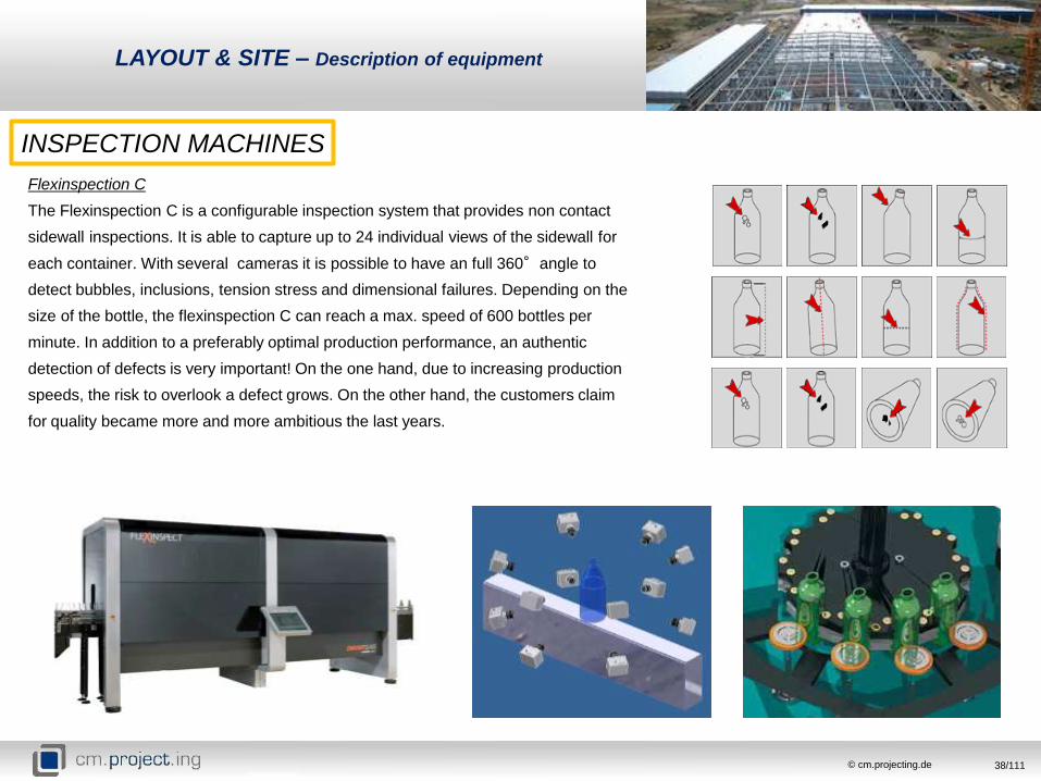
Flexinspection C
The Flexinspection C is a configurable inspection system that provides non contact
sidewall inspections. It is able to capture up to 24 individual views of the sidewall for
each container. With several cameras it is possible to have an full 360°angle to
detect bubbles, inclusions, tension stress and dimensional failures. Depending on the
size of the bottle, the flexinspection C can reach a max. speed of 600 bottles per
minute. In addition to a preferably optimal production performance, an authentic
detection of defects is very important! On the one hand, due to increasing production
speeds, the risk to overlook a defect grows. On the other hand, the customers claim
for quality became more and more ambitious the last years.
LAYOUT & SITE – Description of equipment

39/111© cm.projecting.de
INSPECTION MACHINES
INSPECTION MACHINES UNIT VALUE
camera inspection [mm] height: 38-381, diameter: 16-170
vision plug/ring/dip/saddle
sidewall [type] stress
shoulder [type] stress
base [type]transparency, stress, mould code
reader-DOT or digital
star wheel inspection [type] round: 50 to 84 round: 50 to 84
[type] unround: no unround: no
star cavities [pcs] 24 or 18 24 or 18
finish [type]check, crack, height-inside outside
gauging, LOF
body [type] check, crack, wall thickness, ovality
bottom [type]check, crack, mould code reader-DOT
or digital
configuration concept 1 [pcs] 1 1
configuration concept 2 [pcs] 2 2
LAYOUT & SITE – Description of equipment
European Technologies
Highest requirements (quality standards) of the customer
European quality standards of the equipment
Due to this fact Bralico and Braso actual buy bottles from Germany

40/111© cm.projecting.de
CONVEYING AND PACKAGING
After passing all inspections and checks, the bottles will be prepared
for the packaging. With special conveying belts the bottles will be
transported through the whole cold end area. To compensate waiting
times because of defects or accidents in the cold end area, there are
extra storage tables. With these tables it is possible to store the
bottles for a certain time. Due to that a continuous flow of bottles is
given. At the palletizer the bottles will be accumulated on a separate
table and lined up for the packaging. On an empty pallet a carton layer
is placed on which the first bottles are loaded. After that, the next
carton layer and bottles will be placed on top. This process is repeated
several times. The full loaded pallet will be conveyed to the shrinking
machine where it is wrapped and shrinked with a plastic foil. On the
one hand the shrinking process protects the glass for environmental
influences and on the other hand it enables a stable and secure
transport.
LAYOUT & SITE – Description of equipment

41/111© cm.projecting.de
CONVEYING AND PACKAGING
PALLETIZING MACHINES UNIT VALUE
pallet size [mm] 1200x1000
pallet weight minimum [kg] 300
pallet weight maximum [kg] 1500
pallet height minimum [mm] 500
pallet height maximum [mm] 2400
conveying speed [m/min] 6-12
bottom film [yes/no] no
layers (Bottom layer, intermediate layer, top
layer)[type] plastic or carton
packaging [type]LPG shrinker with
foil magazin
speed shrinking line [pallets /h] ca. 25
LAYOUT & SITE – Description of equipment

42/111© cm.projecting.de
MEDIA SUPPLY – COMPRESSED AIR
BATCH
PLANT
FUNRACE +
FEEDER
IS MACHINES COLD END
COATING
QUALITY
INSPECTION
PALLETIZER +
PACKAGING
CONSUMER TYPE OF DEMAND CONSUMPTION [Nm³/min]
BATCH PLANT CONTROL AIR / FEEDING SILOS WITH RAW MATERIALS HIGH 1,7
FURNACE+ FEEDER CONTROL AIR / COOLING BURNERS, FURNACE CAM UND FEEDER EQUIPMENT HIGH 13,43 / LOW 13,86
IS MASCHINE CONTROL AIR/ COOLING / FROMING PROCESS HIGH 10,59 / LOW 101,6
COLD END COATING AUTOMIZAZION FOR COLD END COATING HIGH 2,0
COLD END CONVEYING CONTROL AIR / EJECTION OF BOTTLES HIGH 0,2
QUALITY INSPECTION EJECTION OF DEFECT BOTTLES HIGH 4,4
PACKAGING CONTROL AIR HIGH 3,1
LAYOUT & SITE – Description of equipment

43/111© cm.projecting.de
MEDIA SUPPLY – COMPRESSED AIR
LAYOUT & SITE – Description of equipment
44/111© cm.projecting.de
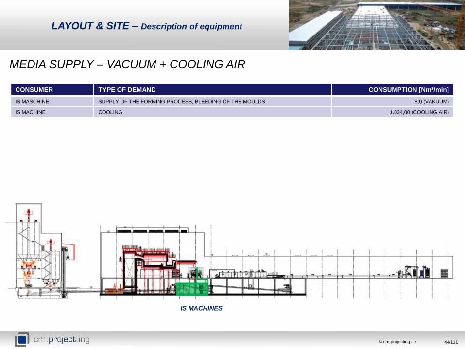
MEDIA SUPPLY – VACUUM + COOLING AIR
IS MACHINES
CONSUMER TYPE OF DEMAND CONSUMPTION [Nm³/min]
IS MASCHINE SUPPLY OF THE FORMING PROCESS, BLEEDING OF THE MOULDS 8,0 (VAKUUM)
IS MACHINE COOLING 1.034,00 (COOLING AIR)
LAYOUT & SITE – Description of equipment

45/111© cm.projecting.de
MEDIA SUPPLY – VACUUM + COOLING AIR
LAYOUT & SITE – Description of equipment

46/111© cm.projecting.de
MEDIA SUPPLY – LPG
CONSUMER TYPE OF DEMAND CONSUMPTION [Nm³/min]
FURNACE + FEDDER MELTING PROCESS 355
HOT END HEATING / PREHEATING OF MOULDS AND MACHINE BELTS 10
ANNEALING LEHR HEATING 50
PACKAGING PACKAGING OF PALETTS WITH SHRINKING FOIL 8
FUNRACE +
FEEDER
HOT END ANNEALING
LEHRPALLETIZER +
PACKAGING
LAYOUT & SITE – Description of equipment

47/111© cm.projecting.de
MEDIA SUPPLY – LPG
Turnaround of the refinery, 45 days
45 days supply stop of LPG, because of the turnaround
During these 45 days the furnace is working with diesel, all other LPG
consumers still running with LPG
45 days LPG storage for the production (excl. Furnace)
The LPG is planned with 4 tanks, each with a storage volume of at least
200 m³ (110 tones LPG). This is conform to a commissioning time of 45 days
LAYOUT & SITE – Description of equipment

48/111© cm.projecting.de
MEDIA SUPPLY – DIESEL
CONSUMER TYPE OF DEMAND CONSUMPTION [l/h]
FURNACE + FEDDER MELTING PROCESS 850
GENERATORS ELECTRICITY 530
FUNRACE +
FEEDER
LAYOUT & SITE – Description of equipment

49/111© cm.projecting.de
MEDIA SUPPLY – DIESEL
Power supply system 50% - Diesel generators 50%
Unstable power supply in Congo
50% electricity network, 50% Diesel tanks to avoid oversizing of the
diesel tanks
Commissioning time 7 days
Heating of the furnace during turnaround
unlimited supply of diesel during the turnaround
firing of the furnace with diesel all other consumers with LPG
Diesel demand for 7 days commissioning time
furnace demand 850 l/h
electricity generators 503 l/h (50% Diesel)
ca. 32.500 l /day
ca. 230.000 for 7days
LAYOUT & SITE – Description of equipment

50/111© cm.projecting.de
MEDIA SUPPLY – ELECTRICITY (DIESEL GENERATOR)
CONSUMER CONNECTION LOAD [kW] CONSUMPTION LOAD [kW]
BATCH PLANT ca. 435 ca. 275
FURNACE + EXHAUST ca. 1.100 ca. 691
IS MACHINES + COOLING AIR ca. 804 ca. 507
ANNEALING LEHR + HE COATING ca. 263 ca. 165
CE LINE (CONVEYING, PACKAGING,
PALLETIZING)
ca. 307 ca. 193
COMPRESSED AIR HIGH / LOW ca. 1.635 ca. 1030
VACUUM ca. 365 ca. 229
WATER SYSTEMS ca. 498 ca. 313
SUB DISTRIBUTION (TGA): OFFICE AND STUFF
BUILDING, WORKSHOPS, SORAGE + OUTDOOR,
CE + HE, LABORATORY
ca. 843 ca. 531,5
SUM ca. 6.250 ca. 3.937,5
Because of the unstable electrical situation, it is necessary to plan with
an alternative electrical supply. It will be realized with Diesel Generators.
Therewith it is possible to be independent of the local unstable electricity
Network. The whole connection load is approximately 4,3 MW. All Diesel
Tanks are designed to supply the Generators with enough diesel for a
min. of 7days commissioning time. The plan is to provide the whole plant
(excl. Furnace) with 50% from the Generators and 50 from the local
electricity network
LAYOUT & SITE – Description of equipment
POWER BALANCE

51/111© cm.projecting.de
MEDIA SUPPLY – COOLING WATER
CONSUMER TYPE OF DEMAND CONSUMPTION [Nm³/h]
PROCESS TECHNIC FURNACE ELECTRODES, STACKER, FEEDER MACHINE, IS MACHINE, CROSS CONVEYOR 11,8
UTILITY TECHNIC COMPRESSED AIR, VACUUM 199,5
FUNRACE + FEEDER +STACKER, FEEDER
MACHINE, IS MACHINE, CROSS CONVEYOR
LAYOUT & SITE – Description of equipment

52/111© cm.projecting.de
MEDIA SUPPLY – COOLING WATER
LAYOUT & SITE – Description of equipment

53/111© cm.projecting.de
FIRE-FIGHTING WATER
CONSUMER TYPE OF DEMAND
PRODUCTION PLANT FIREFIGHTING IN CASE OF EMERGENCY
WATER DRAIN BASINWATER BASIN WELLS FIRE DEPARTMENT
LAYOUT & SITE – Description of equipment

54/111© cm.projecting.de
Fluid Balance
MEDIA SUPPLY CONSUMER CONSUMPTION [Nm³/min]
COMPRESSED AIR LOW FURNACE 12,86
FEDDER 1,0
IS MACHINES 101,6
SUM 115,46
LAYOUT & SITE – Description of equipment
MEDIA SUPPLY CONSUMER CONSUMPTION [Nm³/min]
COMPRESSED AIR HIGH BATCH PLANT 1,7
FURNACE 13,43
COLD END COATING 2,0
SINGLE LINE 0,2
IS MACHINES 10,59
INSPECTION MACHINES 4,4
PACKAGING AND PALLATIZING 3,1
WORKSHOPS, LABORATORIES, UTILITIES 3,0
SUM 38,42
MEDIA SUPPLY CONSUMER CONSUMPTION [Nm³/min]
VACUUM IS MACHINES 8,0
SUM 8,0
MEDIA SUPPLY CONSUMER CONSUMPTION [Nm³/min]
IS COOLING AIR IS MACHINES 1.034,0
SUM 1.034,0
55/111© cm.projecting.de
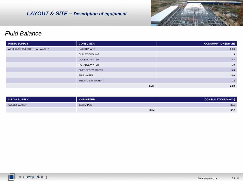
Fluid Balance
MEDIA SUPPLY CONSUMER CONSUMPTION [Nm³/h]
WELL WATER (INDUSTRIAL WATER) BATCH PLANT 0,30
CULLET COOLING 1,5
COOLING WATER 5,8
POTABLE WATER 1,0
EMERGENCY WATER 5,0
FIRE WATER 10,0
TREATMENT WATER 1,2
SUM 24,8
LAYOUT & SITE – Description of equipment
MEDIA SUPPLY CONSUMER CONSUMPTION [Nm³/h)
CULLET WATER SCRAPPER 30,0
SUM 30,0
56/111© cm.projecting.de
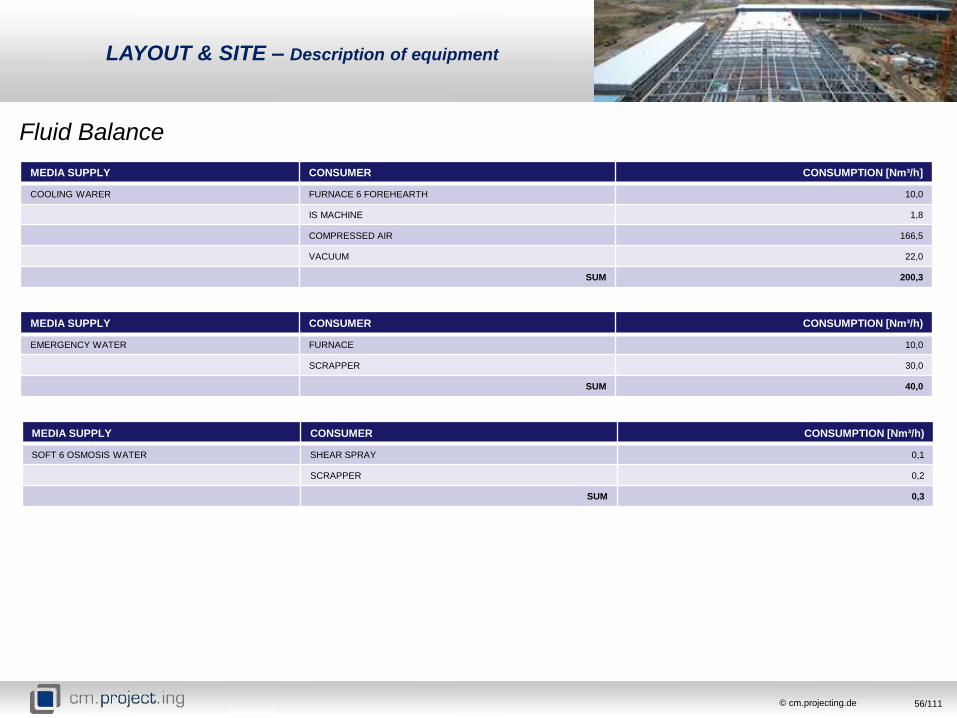
Fluid Balance
LAYOUT & SITE – Description of equipment
MEDIA SUPPLY CONSUMER CONSUMPTION [Nm³/h)
EMERGENCY WATER FURNACE 10,0
SCRAPPER 30,0
SUM 40,0
MEDIA SUPPLY CONSUMER CONSUMPTION [Nm³/h)
SOFT 6 OSMOSIS WATER SHEAR SPRAY 0,1
SCRAPPER 0,2
SUM 0,3
MEDIA SUPPLY CONSUMER CONSUMPTION [Nm³/h]
COOLING WARER FURNACE 6 FOREHEARTH 10,0
IS MACHINE 1,8
COMPRESSED AIR 166,5
VACUUM 22,0
SUM 200,3

57/111© cm.projecting.de
LAYOUT & SITE 2D – Process flow diagram

58/111© cm.projecting.de
LAYOUT & SITE 2D – Process flow diagram

59/111© cm.projecting.de
1) Flue gas channel
2) Regenerator
3) Drip pan
4) IS Cooling air ducting
5) Scrapper
6) Compressed Air &
Vacuum vessels
7) Vacuum pumps
8) Vacuum filter
9) Cullet chutes
10) Cullet conveyors
11) Fans
LAYOUT & SITE 2D – Production building Level -6
4
5
4
9
9
10
87
1 32
1
6
6
10
11
11
11 11
11 11
11
11

60/111© cm.projecting.de
LAYOUT & SITE 2D – Production building Level +4
1) Meeting rooms
2) Offices
3) Manager room
4) Canteen
1
1
2 2
3 2 2 2
4
4

61/111© cm.projecting.de
LAYOUT & SITE 2D – Presentation of civil works
PRODUCTION BUILDING
Production hall.
Length: 138,00 m
Width: 30,00 m
Height: 18,00 m and 8,65 m
Storeys: 3
Area: 4140 m²
Volume: 34200 m3
Social – Technical part.
Length: 138,00 m
Width: 18,00 m
Height: 8,00m
Storeys: 2
Area: 3111 m²
Volume: 9173 m3
Material Solution:
Foundation beams, Reinforced concrete foundation
Steel trusses on concrete pillars spaced every 6.0m span of 30m
Ceilings - reinforced 20cm thick
External walls – Steel cassette wall thickness 120mm
Roof - Trapezoidal sheet, Mineral wool 150kg/m3 , 10cm, Purlins 200, Steel truss
Floors concrete floor reinforcement 30cm thick cured mechanically

62/111© cm.projecting.de
LAYOUT & SITE 2D – Presentation of civil works
WARE HOUSE
Production hall.
Building height: 10 m
Built-up area: 4200 m2
Area: 4200 m2
Storage area: 4200 m2
Volume: 34200 m3
Material Solution:
Foundations slabs and foots, alloys poured
reinforced concrete foundation slabs of wet sited -1.10 m
External walls - Autoclaved aerated concrete thickness:
24 cm, Plastered façade
Roof - Membrane roof with PVC, Mineral wool 150kg/m3,
thickness 10cm PE02 film - vapor barrier, R15 200 channels,
Beam HEA 240 R15, concrete girders
Floors - Concrete floor with reinforcement 30cm thick, cured mechanically
Moisture insulation - PE film, Lean concrete C8/10 - 10cm, Sand bed paved - 20cm

63/111© cm.projecting.de
LAYOUT & SITE 2D – Presentation of civil works
OFFICE BUILDING
Production hall.
Building height: 7,13 m
Built-up area: 376,96 m2
Area: 753,92 m2
Gross Volume: 2601,02 m³
Storeyes: 3
Material Solution:
Foundations slabs and foots, alloys poured reinforced concrete foundation slabs of
wet sited -1.10 m
External walls - Autoclaved aerated concrete thickness: 24 cm, Mineral wool ,
thickness 12cm, Air gap of 1.5, Plastered façade
Roof - Membrane roof with PVC, Mineral wool 150kg/m3, thickness 10cm, PE02
film - vapor barrier, - R15 200 channels, Beam HEA 240 R15
Internal walls - Construction of aerated concrete masonry thickness 12 cm

64/111© cm.projecting.de
LAYOUT & SITE 2D – Presentation of civil works
FIRE BRIGADE BUILDING
Production hall.
Building height: 3,41 m
Built-up area: 130,80 m2
Area: 130,80 m2
Gross Volume: 425,10 m³
Storeyes: 1
Material Solution:
Foundations slabs and strips, alloys poured reinforced concrete foundation slabs of
wet sited
External walls - Autoclaved aerated concrete thickness: 24 cm, Mineral wool
thickness 12cm, Air gap of 1.5, Plastered façade
Roof - slope inclination - 3 %, Membrane roof with PVCMineral wool 150kg/m3,
thickness 10cm, PE02 film, vapor barrierTR trapezoidal sheet, I-joists, steel beams
Floors - Industrial floor thickness 16cm, Moisture insulation, PE film. Lean concrete
C8/10 thickness 10cm
Internal walls: Autoclaved aerated concrete thickness 24 cm
Autoclaved aerated concrete thickness 12 cm

65/111© cm.projecting.de
LAYOUT & SITE 2D – Presentation of civil works
GATEHOUSE BUILDING
Production hall.
Building height: 3,82 m
Built-up area: 34,66 m2
Area: 19,20 m2
Gross Volume: 136,74 m³
Storeyes: 1
Material Solution:
The building built on the foundation plate , 10cm thick reinforced concrete,
reinforced with rods ø6 , with a mesh 20x20cm , top and bottom . Plate
supported on the perimeter foundation walls , concrete 15cm thick . The
foundation made of concrete B-15 , wherein the foundation walls 10cm lean
concrete B-7
Posts and beams are designed with hollow sections 100x100x3. The whole
structure bolted M-10 , Class 4.8 . Construction concentrated stitches M -10. All
steel parts shall be protected with anticorrosive paint
Internal walls - The walls of sandwich panels filled with mineral wool . 8 cm thick
External walls - Designed the exterior walls of sandwich panels with mineral wool
filling 15cm thick
Roof - Slope inclination - 3 % , trapezoidal roof covering
Insulation – mineral wool, polystyrene, polyurethane foam, PVC film flange

66/111© cm.projecting.de
LAYOUT & SITE 3D – Site overview

67/111© cm.projecting.de
LAYOUT & SITE 3D – Site overview

68/111© cm.projecting.de
LAYOUT & SITE 3D – Site overview

69/111© cm.projecting.de
LAYOUT & SITE 3D – Site overview

70/111© cm.projecting.de
LAYOUT & SITE 3D – Site overview

71/111© cm.projecting.de
LAYOUT & SITE 3D – Site overview

72/111© cm.projecting.de
LAYOUT & SITE 3D – Site overview

73/111© cm.projecting.de
LAYOUT & SITE 3D – Site overview

74/111© cm.projecting.de
LAYOUT & SITE 3D – Site overview

75/111© cm.projecting.de
LAYOUT & SITE 3D – Site overview

76/111© cm.projecting.de
PLANT ORGANIZATION –Organigram, plant structure
Plant M anager
Product ion
M anagement
Product ion
Planning
Plant
M aintenance
Electr ical
M aintenance
M ould
M anagement
HE
Job Change
Planning
OperationW orkshop W orkshopM ouldshop
IS Repair +
M aintenance
Logist ic
Construct ion
W are Handling/
Lehr
M aintenance
Customs
CE
Shift Supervisor
HE
Shift Supervisor
Repair
M anuel
Repair
Automat ic
M ould
Quality
CE M anager
CE
Job Change
HE M anager
Quality
M anagement
LaboratoryQuality
M anagement
CE
M aintenance
M elt ing
M anagement
Furnace/ Feeder
Supervisor
Batch House
Supervisor
M anaging Direc tor
Forming
Operater
Pallet iser
Operator
Line Ass is tant
Operator
CE
Shift Supervisor
CE
Job Change
CE
M aintenance
Pallet iser
Operator
Line Ass is tant
Operator
Quality
Super intendant
Gauge Clerk
Quality Field
Officers
Quality Auditor
Quality /
Laboraoty Clerk
Furnace Control
Room
Batch Control
Room
Production Process
Total staff ca. 150

77/111© cm.projecting.de
General Management
General M anagement
Human Ressource
Depar tment
Projects
M anagement
Saftey & Health
M anagement
Trainee &
Apprentice
Sales &
M arket ing
Project M anager
ICT Depar tmentFinanc ial
Departm ent
M anaging Direc tor
Sales &
M arket ing
Consultant
Financ ial Clerk
Financ ial
Account ing
Buyer
Store Clerk
Store Supervisor
Payroll-
Administ rator
Human
Ressource
Officer
Trainer /
Assessor
Recept ionist
Nurse
Training
Consultant
IT Technic ians
Systems
Engineers
Help Desk
Technician
Safe & Healthy
M anager
Trainee /
Apprentice HE
Trainee /
Apprentice CE
Trainne /
Apprentice
Administ rat ion
Total staff ca. 50
PLANT ORGANIZATION –Organigram, plant structure

78/111© cm.projecting.de
PLANT ORGANIZATION –Training & TAA

79/111© cm.projecting.de
TIME PLANNING

80/111© cm.projecting.de
TIME PLANNING

81/111© cm.projecting.de
TIME PLANNING

82/111© cm.projecting.de
The Glass will be produced according to a specific recipe. The main components are sand,
limestone, soda, dolomite, sodium sulphate and alumina. Some of these raw materials will be
mined directly in Congo. It includes sand, limestone, and Dolomite. For limestone and dolomite it
is important to note, that these raw materials are not in the right size to use it for the glass
production. Before filling in the batch silos it has to be crushed in the right size. For the
preparation of these raw materials it could be a solution, to buy a crusher which would be
placed above the production building.
NEEDED CAPACITY
Raw materials Chemical formula Capacity [in t/d] Capacity [in t/m] Capacity [in t/y]
Sand (Quartz sand) 2.818,80 34.295,40
Limestone CaCO3 16,13 483,90 5.887,45
Soda Na2CO3 31,36 940,80 11.446,40
Dolomite CaMg[CO3]2 13,01 390,30 4.748,65
Sodium sulphate Na2SO4 1,04 31,20 379,60
Alumina Al2O3 3,64 109,20 1.328,60
GRAIN SIZE [in mm]
Raw materials < 0,1 0,1 – 0,2 0,1 - 0,315 0,1-0,5 0,2-0,315 0,315-0,5 0,315-0,63 0,5 0,5-1,0 > 0,63 0,63-1,0 > 1,0 1,0-1,6 1,6-2,0 > 2,0
Sand (Quartz sand) 40-60% 30-50% 5-15% 0%
Limestone 3-6 % 30-35 % 25-30 % 30-35 % 5-10 % < 5 % 0%
Soda 3-6 % 25-30 % 20-25 % 30-35 % 5-10 %
Dolomite 10-20 % 30-40 % 10-15 % 10-15 % 10-15 % 5-10 % 0%
Sodium sulphate 23-28 % 70-75 % 1-4 %
Feldspar 65-70 % 30-35 % < 1 % 0%
RAW MATERIALS ORGANIZATION –
Raw materials situation and infrastructure

83/111© cm.projecting.de
RAW MATERIALS ORGANIZATION –
Raw materials situation and infrastructure
PRINCIPAL CONSTITUENTS OF GLASS
SODA ASH
ALUMINA
SODIUM SULPHATELIME
STONE
DOLOMITE
SANDca 59 %
ca 19,7 %
ca 2,29%
ca 10,14%
ca 8,18%
ca 0,65%
~ Soda Ash
~ Alumina
~ Sodium
Sulphate
~ Sand
~ Dolomite
~ Lime Stone
import
import
import

84/111© cm.projecting.de
POINTE NOIRE (SAND)
Socofran (Mengo/Liambou, Loueme)
Vindoulou
Pointe Noire
Pointe Noire
Distance: 1,5 km
Driving time: 0h 10min.
RAW MATERIALS ORGANIZATION –
Raw materials situation and infrastructure
DOLISIE (Dolomite (rough stone))
Dolisie
Niari
DOLISIE (Lime Stone (rough stone))
Ditadi département de la Bouenza-Republic Congo
Dolisie
Niari
Dolisie
Distance: 158 km
Driving time: 2h 30min.

85/111© cm.projecting.de
RAW MATERIALS ORGANIZATION –
Raw materials situation and infrastructure
PROBLEMS
Size of raw materials
The raw materials have to be a specific size to feed it into the batch silos.
Dolomite and lime stone are not in the right size to use it for the glass
production process, if its will be mind at Dolisie.
A possible solution is to crush the raw materials inside the plant area.
Therefore it needs area to store the material and a crusher where the lime
stone and dolomite will be treated to the right size.
Moist of the sand
In Congo there is a rather damp climate. So it could be possible that the sand
will be too moist. This would have consequences to the machines and batch,
because the moist sand will be clump together. Thereby the machines and
belts in the batch house could be damaged. A possible solution is to dry the
sand with and optional sand dryer.
Contamination
All raw materials have to be available in a certain quality. Contamination with
other compounds, which could have negative influence to the glass production,
may not cross over specific values. Due to this fact for each raw material
must be carried out a analysis.

86/111© cm.projecting.de
CAPEX – Overview
SYSTEM FOB-PRICE IN €
BATCH PLANT 3.552.600,00
WORK PACKAGE POSITION
… …
RAW MATERIAL HANDLING MECHANICAL RAW MATERIAL FEDDING
PREMIX PREPARATION
MANUAL FEEDING
MECHANICAL SAND AND CULLET FEEDING
ACCESSORIES FOR SILO PLANT OUTLET CONE
CONNECTION FLANGES
BIN ACTIVATOR
DOSING WEIGHING MIXING SCALES
DOSING UNITS
MIXER UNITS
CONVEYORS, CHUTES; HOPPERS
BATCH AND CULLET TRANSPORT ELEVATORS
CHUTES
CONVEYORS
MAGENTIC SEPARATOR
… …
ENGINEERING BASIC ENGINEERING
DETAILED ENGINEERING
SITE SERVICE SUPERVISION, COMMSSIONING AND TRAINING
INSTALLATION (MECHANICAL AND ELECTRICAL)

87/111© cm.projecting.de
SYSTEM FOB-PRICE IN €
FURNACE 9.996.190,00
WORK PACKAGE POSITION
… …
COMBUSTION AIR SUPPLY AND WASTE
GAS SYSTEMRADIAL FANS
VALVES,DAMPER BLOCKS, COMPENSATORS
PIPE SYSTEM
COMBUSTION SYSTEM FOR GAS GAS STATION
BURNERS AND ACCESSORIES
VALVES, PRESSURE REDUCER,
BATCH CHARGING SYSTEM BATCH CHARGING MACHINE
CONTROL CABINET
METERING AND CONTROL SYSTEM TEMPERATURE METERING
COMBUSTION AIR FLOW METERING
FURNACE PRESSURE METERING
GLASS LEVEL METERING AND CAMERA/TV SYSTEM
FURNACE & FOREHEARTHS REFRACTORY MATERIAL
STEELWORK
HEATING SYSTEM
… …
ENGINEERING BASIC ENGINEERING
DETAILED ENGINEERING
SITE SERVICE SUPERVISION, COMMSSIONING AND TRAINING
ASSEMBLY OF STEEL AND REFRACTORY MATERIAL
CAPEX – Overview

88/111© cm.projecting.de
SYSTEM FOB-PRICE IN €
IS & INSPECTION MACHINES 11.572.152,70
WORK PACKAGE POSITION
… …
SERVO FEEDER WITH PLUNGER PUNGER MECHANISM, SHEAR MECHANISM
SPOUTS, EQUALIZING SECTION
FEEDER REDRACTORIES
8 SECTION 5 1/2“ DOUBLE GOB PIPING, CABLING MOULD SUPPORTING MECHANISM
GOB DISTRIBUTOR, SCOOP HOLDER, FUNNELS
MACHINE CONTROL EQUIPMENT, MOTORS FOR WARE
HANDLING
FEEDER MECHANISM, TUBES, CONVEYING EQUIPMENT,
MOULD HOLDERS,
MOULDS MOULD PRE HEATING OVEN, 6 SETS OF MOULD
SERVICE EQUIPMENT AUXILIARY EQUIPMENT
SUPPLY PIPING, TOOLS, FACTORY CONNECTIONS
WARE TRANSEFER & CROSSCONVEYORBASIC WARE TRANSFER, DRIVE AND MOTOR, PUSHERS
AND FILLER PLATES, CROSS CONVEYOR SYSTEM
STACKER SERVO STACKER
… …
INSPECTION MACHINES FLEX INSPECTION C
FLEX INSPECTION M
SERVICES TRAINING AT EMHART
TRAINING ON SITE
INSTALLATION AND COMMISSIONING
CAPEX – Overview

89/111© cm.projecting.de
SYSTEM FOB-PRICE IN €
ANNEALING LEHR 666.900,00
WORK PACKAGE POSITION
… …
HEATING SYSTEM BURNERS, BUNRER TUBES, GAS RING PIPES
FANS
COOLING SYSTEM COOLING ZONES
COOLING FANS
CIRULATION COOLING AIR SYSTEM
DISCHARGE TABLE MOTOR DRIVE SYSTEM
PRESSURE ROLLER, DISCHARGE ROLLER
CONVEYING BELTS
CONTROL MONITORING CONTROL PANEL
TEMPERATURE CONTROL, SPEED CONTROL
COLD END COATINGSPRAYING UNIT, COLD END BRIDGE, CONTROL UNIT
DOSING UNIT
… …
SERVICE INSTALLATION
TRAINING
COMMISSIONING AND START UP
CAPEX – Overview

90/111© cm.projecting.de
SYSTEM FOB-PRICE IN €
COLD END CONVEYING AND PACKAGING 1.802.850,30
WORK PACKAGE POSITION
… …
TRANSTECH BOTTLE CONVEYORS CROSS CONVEYOR AT THE LEHR
BUFFER TABLE
BOTTLE CONVEYOR, BOTTLE ALIGNER
BOTTLE SPACER
ELECTRICAL CABINET AND CONTROL DESK
SORT OUT CONVEYOR
SEMITECH PALLETIZER ROW STACKER
ACCUMULATION TABLE
LAYER TRANSFER INCL. CENTRING DEVICE
CHAIN CONVEYOR, ROLLER CONVEYOR
CORNER CONVEYOR, DRIVE UP PROTECTION
SHRINKING LINE CONVEYOR, CENTRING DEVICE
SHRINKING SYSTEM, SHRINKING MACHINE
… …
SERVICES INSTALLATION
TRAINING
COMMISSIONING
CAPEX – Overview

91/111© cm.projecting.de
SYSTEM FOB-PRICE IN €
UTILITIES 9.436.105,52
WORK PACKAGE POSITION
… …
COMPRESSED AIRCOMPRESSORS; DRYER, RESERVATORIES, VALVES
FILTERS, OIL TREATMENT, CYCLONE, PIPING
VACUUMPUMPS, FILTER, CONDENSATE DRAINER, RECEIVER,
PIPING, ELECTRICAL CABINET
IS COOLING AIR
RADIAL VENTILATOR, FREQUENCY CONVERTER,
VALVES, PIPING, DUCTING, ELECTRICAL CABINET,
CABLING
COOLING WATER
PUMPS, COOLING TOWERS, RESERVATORIES,
INSTRUMENTATION, VALVES, MANIFOLDS, MOTORS,
VENTILATION, FILTER
PROCESS WATERPUMPS, RESERVATORIES, COOLING TOWERS, WASTE
OIL TANK SYSTEM
WASTE WATERPRE-TREATMENT INCL. CONTROL CABINET, SOFTENING
UNIT, PUMP STATION, WATER TREATMENT UNIT, PIPING
OSMOSIS + SHEAR AND SCOOP SPRAYOSMOSIS PLANT, SHEAR & SCOOP SPRAY SYSTEM,
NOZZLES VALV BOXES, PIPING
EXTINGUISHING WATER PMPS, RESERVATORIES, DIESEL TANK FIRE PUMPS
LPG EQUIPMENT,MEASUREMENT AND CONTROL EQUIPMENT
DIESEL EQUIPMENT,MEASUREMENT AND CONTROL EQUIPMENT
ELECTRIC
MV SWITCH GEAR, TRANSFORMERS INCL. CABLE, lv
MAIN DISTRIBUTION PANELS, lv DISTRIBUTION PANELS,
CABLE TRAYS
IT HARDWARE SOFTWARE
MAIN PIPING MAIN PIPING
SERVICES
MAIN PIPING, ELECTRICAL AND MECHANICALL
INSTALLATION
CAPEX – Overview

92/111© cm.projecting.de
SYSTEM FOB-PRICE IN €
PRODUCTION BUILDING 4.950.000,00
WORK PACKAGE POSITION
PRODUCTION BUILDING LEVEL -6 PREPARATION WORKS
PRODUCTION BUILDING LEVEL 0 EARTH WORKS
PRODUCTION BUILDING LEVEL +4 CONCRETE WORKS
FORMWORKS
PE FILM UNDER FLOOR SLAB
AGGREAGATE
MASONRY HOLLOW CHIPBOARD, CEMENT MORTAR
MORTAR CEMENT PLASTER
STAIRCASE
BEAMS
FLOORS
PAVINGS
CAPEX – Overview

93/111© cm.projecting.de
SYSTEM FOB-PRICE IN €
WARE HOUSE 1.320.000,00
WORK PACKAGE POSITION
WARE HOUSE PREPARATION WORKS
EARTH WORKS
CONCRETE WORKS / LEAN CONCRETE
FORMWORKS
PE FILM UNDER FLOOR SLAB
AGGREAGATE
MASONRY HOLLOW CHIPBOARD, CEMENT MORTAR
SMOOTH FINISH TO CONCRETE SLAB
STAIRCASE
BEAMS
FLOORS
PAVINGS
CAPEX – Overview

94/111© cm.projecting.de
SYSTEM FOB-PRICE IN €
OFFICE BUILDING 1.367.400,00
WORK PACKAGE POSITION
OFFICE BUILDING PREPARATION WORKS
EARTH WORKS
CONCRETE WORKS / LEAN CONCRETE
FORMWORKS
PE FILM UNDER FLOOR SLAB
AGGREAGATE
MASONRY HOLLOW CHIPBOARD, CEMENT MORTAR
SMOOTH FINISH TO CONCRETE SLAB
STAIRCASE
BEAMS
FLOORS
PAVINGS
CAPEX – Overview

95/111© cm.projecting.de
SYSTEM FOB-PRICE IN €
FIRE BRIGADE BUILDING 183.878,00
WORK PACKAGE POSITION
FIRE BRIGADE BUILDING PREPARATION WORKS
EARTH WORKS
CONCRETE WORKS / LEAN CONCRETE
FORMWORKS
PE FILM UNDER FLOOR SLAB
AGGREAGATE
MASONRY HOLLOW CHIPBOARD, CEMENT MORTAR
BEAMS
FLOORS
CAPEX – Overview

96/111© cm.projecting.de
SYSTEM FOB-PRICE IN €
GATEHOUSE 12.973,00
WORK PACKAGE POSITION
GATE HOUSE PREPARATION WORKS
EARTH WORKS
CONCRETE WORKS / LEAN CONCRETE
FORMWORKS
PE FILM UNDER FLOOR SLAB
AGGREAGATE
MASONRY HOLLOW CHIPBOARD, CEMENT MORTAR
MORTAR CEMENT PLASTER
BEAMS
FLOORS
CAPEX – Overview

97/111© cm.projecting.de
CAPEX – Overview

98/111© cm.projecting.de
CAPEX – Overview

99/111© cm.projecting.de
CAPEX – Overview

100/111© cm.projecting.de
CAPEX – Overview

101/111© cm.projecting.de
CAPEX – Roughly cash flow planning

102/111© cm.projecting.de
CAPEX – Roughly cash flow planning

103/111© cm.projecting.de
CAPEX – Roughly cash flow planning
104/111© cm.projecting.de
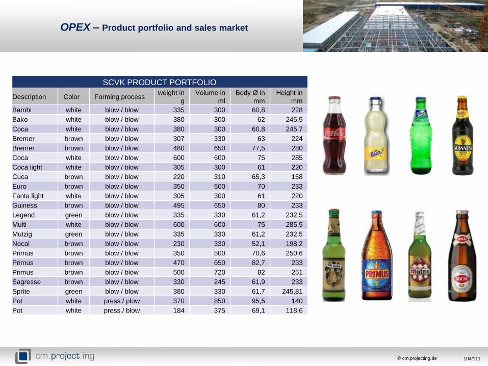
OPEX – Product portfolio and sales market
SCVK PRODUCT PORTFOLIO
Description Color Forming processweight in
g
Volume in
ml
Body Ø in
mm
Height in
mm
Bambi white blow / blow 335 300 60,8 228
Bako white blow / blow 380 300 62 245,5
Coca white blow / blow 380 300 60,8 245,7
Bremer brown blow / blow 307 330 63 224
Bremer brown blow / blow 480 650 77,5 280
Coca white blow / blow 600 600 75 285
Coca light white blow / blow 305 300 61 220
Cuca brown blow / blow 220 310 65,3 158
Euro brown blow / blow 350 500 70 233
Fanta light white blow / blow 305 300 61 220
Guiness brown blow / blow 495 650 80 233
Legend green blow / blow 335 330 61,2 232,5
Multi white blow / blow 600 600 75 285,5
Mutzig green blow / blow 335 330 61,2 232,5
Nocal brown blow / blow 230 330 52,1 198,2
Primus brown blow / blow 350 500 70,6 250,6
Primus brown blow / blow 470 650 82,7 233
Primus brown blow / blow 500 720 82 251
Sagresse brown blow / blow 330 245 61,9 233
Sprite green blow / blow 380 330 61,7 245,81
Pot white press / plow 370 850 95,5 140
Pot white press / blow 184 375 69,1 118,6

105/111© cm.projecting.de
OPEX – Product portfolio and sales market
Bralico: - Pointe Noire
- Brazzaville (future)
- Oyo (future)
Brasco: - Brazzaville
- Pointe Noire
SCVK: - Pointe Noire
SALES MARKET IN
CONGO

106/111© cm.projecting.de
OPEX – Product portfolio and sales market
SALES MARKET POTENTIAL CUSTOMER
BREWERY MEMBER OF THE GROUP COUNTRY SALES VOLUME [tonnage/y] SALES VOLUME [bottles/y]
Brasco Heineken / CFAO Congo ca. 6.262 ca. 13.514.788
Bralico (point Noire) Independent Congo estimation 3.240 estimation 7.200.000
Bralico (Brazzaville) Independent Congo estimation 3.240 estimation 7.200.000
Bralico (Oyo) Independent Congo estimation 3.240 estimation 7.200.000
Bracongo (RDC) Castel Groupe Kinshasa ca. 4.350 ca. 9.667.357
GSCA Guinness Castel Groupe Cameroun ca. 3.476 ca. 7.725.000
Bralima Heineken Kinshasa/Boma ca. 11.330 ca. 25.179.982
Sobraga Castel Groupe Gabon ca. 8.037 ca. 17.100.000
Soeguibe Castel Groupe Equatorial Guinea ca. 2.289 ca. 5.450.000
SUM 45.464 100.237.127
Pack to melt estimation 77,5%
SCVK‘s estimated salable tonnage for a capacity of 115 tpd at the beginning ca. 32.000 t/y

107/111© cm.projecting.de
OPEX - Estimation
YEARLY OPERATIONAL COSTS
TOTAL COST [€/ a nnum ] COST PER SELLABLE TON [€] % OF TOTAL
ENERGY 1.910.995,53 60,14 18,25
RAW MATERIAL 3.841.006,58 120,87 36,68
LABOUR 2.377.544,00 74,82 22,71
PACKAGING MATERIALS 471.970,27 14,85 4,51
CONSUMABLES 857.767,20 26,99 8,19
MAINTENANCE 260.000,00 8,18 2,48
MISSCELANEOUS 752.000,00 23,66 7,18
DISTRIBUTION COSTS 0,00 0,00 0,00
TOTAL 10.471.283,58 329,51 100,00

108/111© cm.projecting.de
TOTAL COST [€/ a nnum ] COST PER TON [€]
OPERATIONAL COSTS 10.471.283,58 329,51
DEPRICIATION 2.935.101,42 92,36
CREDIT COSTS 0,00 0,00
TOTAL YEARLY COSTS 13.406.385,00 421,87
ESTIMATED PROFIT MARGIN [%] 15
EFFECTIVE SIMULATED SALES PRICE [€/ t] 485,15
CURRENT MARKET PRICE [€/ t] 596,00
EFFECTIVE SIMULATED PTM [%] 77,51
EFFECTIVE SIMULATED TURNOVER [€/ a ] 15.417.342,75
EFFECTIVE SIMULATED EBT [€/ a ] 2.010.957,75
OPEX - Estimation

109/111© cm.projecting.de
OPEX - Estimation

110/111© cm.projecting.de
OPEX - Estimation

111/111© cm.projecting.de
CONGOS’S BENEFITS