Embed Size (px)
Citation preview

Umformen
Forming
Hole andpunching units

Umformen
Forming
Hole punching and punching unitsForming technology is a business area of the TÜNKERS Group who operates in the field of industrial robotsand offers the nine automation modules - clamping, positioning, gripping, forming, welding, dispensing, rotating,conveying and transporting.
By forming we mean punching, bending, shaping and joining metal sheets or plastic parts that are used, interalia, in car body manufacturing in the automotive industry.
We are focussed on specialized installations that are individually designed for the respective application.
By this catalogue and in addition to this special programme, we offer you a product range of standard productswith pre-assembled C-frames, drives and application tools. In the best sense this complete modular designsystem enables you to implement your own solution for your particular field of application very rapidly and –by using complementary components – to re-define a new application tomorrow.
It remains to mention that these modules are available ex works and therefore are at your disposal even atshort notice.
Mr. André Michels will answer any questions you may have under tel.: +49 2102 4517-508 [email protected].
We will be pleased to answer your request
André Tünkers Josef-Gerhard Tünkers Olaf Tünkers
2 |
FORMING
Id.-Nr. 1216058 · 7/2017 QS according to VDA 6, Part 4 + DIN EN ISO9001:2000

Subject to technical modifications.
Umformen
Forming
| 3
Punching unit, hole Ø 2-7 mm
FORMING
Only round cut Hole diameter with material thickness 3 2-7 mm1)
Hole diameter with material thickness 5, max. 5 mm1)
Material thickness for steel St 60 0,3-5 mm1) Hole Ø 6 to 7 mm only in material thickness upto 3 mm.
Punching tools(punch and die) have to be ordered separately.See table below.
* Lower edge of punch and upper edge of die are flush
Punching unit without punching tools Punching tools have to be ordered separately
Order No.
Throatdepthrange
Hole ØD
WidthB
Weight~(kg)
Punch kit Order No.
Round hole PunchOrder No.
Die Order No.
100-60 160 2-7 20 5,2 500-Ø-BL-ST 300-Ø 400-Ø-BL-ST
Insert in Order No.: Ø = hole Ø, BL = Material thickness, ST = material and strength. See also punching tools.

Umformen
Forming
4 |
Punching unit, hole Ø 2-13 mm
FORMING
Subject to technical modifications.
Round and shaped cuts +Hole diameter with material thickness 3 2-13 mm1)
Hole diameter with material thickness 5, max. 11 mm1)
Material thickness for steel St 60 0,3-5 mm1) hole Ø 12 to 13 mm only in material thicknessup to 3 mm.
Punching tools(punch and die) have to be ordered separately.See table below.
AccessoriesSee pages accessories.
* Lower edge of punch and upper edge of die are flush
It is possible to punch holes with Ø 2–7 mm by using reduction bushes and reduction sockets, which enable the use of the punchand die from the next smaller size of punching units.
Punching unit without punching tools Punching tools have to be ordered separately+
Order No.
Throatdepthrange
Hole ØD
WidthB
Weight~(kg)
Punch kit Order No.
Round hole PunchOrder No.
Die Order No.
Shaped punch Punch kitOrder No.
101-200 F 200 2-13 30 7,8 500-Ø-BL-ST 301-Ø 401-Ø-BL-ST 501-Formhole-BL-ST
Insert in Order No.: Ø = hole Ø, BL = Material thickness, ST = material and strength. See also punching tools.

Subject to technical modifications.
Umformen
Forming
| 5
Punching unit, hole Ø 25-40 mm
FORMING
Round and shaped cuts +Hole diameter with material thickness 3 25-40 mm1)
Material thickness for steel St 60 0,3-5 mm1) Punching tools for holes with Ø 20–25 mm areavailable on request in special sizes
Punching tools(punch and die) have to be ordered separately.See table below.
AccessoriesSee pages accessories.
* Lower edge of punch and upper edge of die are flush
Punching unit without punching tools Punching tools have to be ordered separately+
Order No.
Throatdepthrange
Hole ØD
WidthB
Weight~(kg)
Punch kit Order No.
Round hole PunchOrder No.
Die Order No. Shaped punch
Insert in Order No.: Ø = hole Ø, BL = Material thickness, ST = material and strength. See also punching tools.
Punching unit without punching tools Punching tools have to be ordered separately+
Order No.
Throatdepthrange
Hole ØD
WidthB
Weight~(kg)
Punch kit Order No.
Round hole PunchOrder No.
Die Order No.
Shaped punch Punch kitOrder No.
101-200 F 200 25-40 75 14 503-Ø-BL-ST 303-Ø 403-Ø-BL-ST 503-Formhole-BL-ST

Umformen
Forming
6 |
Punching unit, hole Ø 8-25 mm
Subject to technical modifications.
FORMING
Round and shaped cuts +Hole diameter with material thickness 3 8-25 mm1)
Material thickness for steel St 60 0,3-5 mm1) It is possible to punch holes with Ø 2–8 mm byordering a reduction bush and reduction socket
Punching tools(punch and die) have to be ordered separately.See table below.
AccessoriesSee pages accessories.
* Lower edge of punch and upper edge of die are flush
Punching unit without punching tools Punching tools have to be ordered separately+
Order No.
Throatdepthrange
Hole ØD
WidthB
Weight~(kg)
Punch kit Order No.
Round hole PunchOrder No.
Die Order No.
Shaped punch Punch kitOrder No.
102-200 F 200 8-25 55 15 502-Ø-BL-ST 302-Ø 402-Ø-BL-ST 502-Formhole-BL-ST
Insert in Order No.: Ø = hole Ø, BL = Material thickness, ST = material and strength. See also punching tools.

Subject to technical modifications.
Umformen
Forming
| 7
Punching unit, hole Ø 40-63 mm
FORMING
Round and shaped cuts +Hole diameter 40-63 mmMaterial thickness for steel St 60 0,3-5 mm
Punching tools(punch and die) have to be ordered separately.See table below.
AccessoriesSee pages accessories.
* Lower edge of punch and upper edge of die are flush
Punching unit without punching tools Punching tools have to be ordered separately+
Order No.
Throatdepthrange
Hole ØD
WidthB
Weight~(kg)
Punch kit Order No.
Round hole PunchOrder No.
Die Order No.
Shaped punch Punch kitOrder No.
104-200 F 200 40-63 108 20 504-Ø-BL-ST 304-Ø 404-Ø-BL-ST 504-Formhole-BL-ST
Insert in Order No.: Ø = hole Ø, BL = Material thickness, ST = material and strength. See also punching tools.

Umformen
Forming
8 |
Punching unit, hole Ø 2-13 mm
Subject to technical modifications.
FORMING
Round and shaped cuts +Hole diameter with material thickness 3 2-13 mm1)
Hole diameter with material thickness 5, max. 11 mmMaterial thickness for steel St 60 0,3-5 mm1) Hole Ø 12 to 13 mm only in material thicknessup to 3 mm.
Punching units of series 111 areparticularly suitable for punchingsmall profiles. For special applica-tions, either a special die blockwith a small special die (see illus-tration) can be used or a one-piece block die (see illustration).In both cases, the punching ofvery small profiled parts is possi-ble after removing the standarddie block.
Punching tools(punch and die) have to be ordered separately.See table below.
AccessoriesSee pages accessories.
* Lower edge of punch and upper edge of die are flush
Punching unit without punching tools Punching tools have to be ordered separately+
Order No.
Throatdepthrange
Hole ØD
WidthB
Weight~(kg)
Punch kit Order No.
Round hole PunchOrder No.
Die Order No.
Shaped punch Punch kitOrder No.
111-125 F 125 2-13 30 6 501-Ø-BL-ST 301-Ø 401-Ø-BL-ST 501-Formhole-BL-ST
Insert in Order No.: Ø = hole Ø, BL = Material thickness, ST = material and strength. See also punching tools.

Subject to technical modifications.
Umformen
Forming
| 9
Punching unit, hole Ø 8-22 mm
FORMING
Punching unit without punching tools Punching tools have to be ordered separately+
Order No.
Throatdepthrange
Hole ØD
WidthB
Weight~(kg)
Punch kit Order No.
Round hole PunchOrder No.
Die Order No.
Shaped punch Punch kitOrder No.
112-200 F 200 8-22 63 16 512-Ø-BL-ST 312-Ø 402-Ø-BL-ST 512-Formhole-BL-ST
Round and shaped cuts +Hole diameter 8-22 mmMaterial thickness for steel St 60 2-10 mm
With small modifications thesepunching units are suitable forpunching L-, U-, or Z-profiles, seeapplication example.
Punching tools(punch and die) have to be ordered separately.See table below.
AccessoriesSee pages accessories.
* Lower edge of punch and upper edge of die are flush
Insert in Order No.: Ø = hole Ø, BL = Material thickness, ST = material and strength. See also punching tools.

Umformen
Forming
10 |
Punching unit, hole Ø 22-38 mm
Subject to technical modifications.
FORMING
Round and shaped cuts +Hole diameter 22-38 mmMaterial thickness for steel St 60 2-10 mm
With small modifications thesepunching units are suitable forpunching L-, U-, or Z-profiles, seeapplication example.
Punching tools(punch and die) have to be ordered separately.See table below.
AccessoriesSee pages accessories.
* Lower edge of punch and upper edge of die are flush
Insert in Order No.: Ø = hole Ø, BL = Material thickness, ST = material and strength. See also punching tools.
Punching unit without punching tools Punching tools have to be ordered separately+
Order No.
Throatdepthrange
Hole ØD
WidthB
Weight~(kg)
Punch kit Order No.
Round hole PunchOrder No.
Die Order No.
Shaped punch Punch kitOrder No.
113-200 F 200 22-38 85 21 513-Ø-BL-ST 313-Ø 403-Ø-BL-ST 513-Formhole-BL-ST

Subject to technical modifications.
Umformen
Forming
| 11
90° notch units, notch size 63x63 mm
FORMING
600-063 R with gauging table 800-063S
Cutting angle 90°Max. notch size 63x63 mmMaterial thickness for steel St 60 0,3-8 mm
The notch units, adjusted to a dieclearance of 0.1 mm, are pre-setin the factory for cutting materialwith a thickness of 0.3–3 mm.Withthe metal compensation sheets(0.2 mm) included in the delivery,the die clearance can be set to 0.2 or 0.3 mm for greater materialthickness.
With the adjustable gauging tablethe notch size can be adjustedcontinuously in two directionsfrom 0–63 mm. The gauging tablehas to be ordered separately.
* Notch unit closed, upper blade inserted to full depth
90° notch units without gauging tablewith cutting tools Gauging table (adjustable) has to be ordered separately
Version Weight Appropriate for notch units Weight
Left hand Right hand600-063 L 600-063 R
Order No. Order No. ~ (kg) Order No. ~ (kg)
600-063 L 600-063 R 15 800-063 S 6,5
Umformen
Forming
12 |
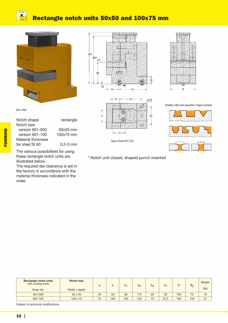
Rectangle notch units 50x50 and 100x75 mm
Subject to technical modifications.
FORMING
601-050
Notch shape rectangleNotch sizeversion 601-050 50x50 mmversion 601-100 100x75 mmMaterial thickness for steel St 60 0,3-3 mm
The various possibilities for usingthese rectangle notch units are illustrated below.The required die clearance is set inthe factory in accordance with thematerial thickness indicated in theorder.
* Notch unit closed, shaped punch inserted
Rectangle notch unitswith cutting tools
Order No.
Notch size
Width x depth
a b A1 A3 A4 A7 B B2Weight~(kg)
601-050 50 x 50 50 50 90 110 50 25 100 75 16
601-100 100 x 75 75 100 100 120 75 37,5 150 100 27

Subject to technical modifications.
Umformen
Forming
| 13
Radius cut unit, R 5-30 mm
FORMING
Possible radii R 5, 10, 15, 20, 25, 30 mmCutting angle � 90°Material thickness for steel St 37,max. 5 mm
In addition to the pneumatic and hydraulic radius cut units,pressoperated radius cut units areintroduced on this page.By adjusting the liwith stops the radius tool unit enables the production of six different 90° radiiwith only one punching tool.The graduation of the radii is divided into steps of 5 mm from R 5 mm up to R 30 mm.Other radii are available on request.
* Radius cut unit closed, upper punch completely inserted
Radius cut unit with cutting tools
Order No. Possible radiiR
Weight~ (kg)
606-30 5,10,15,20,25,30 22
Note – Please state preferred material quality and thickness when ordering
Umformen
Forming
14 |
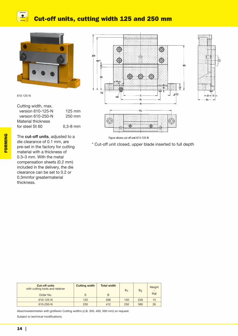
Cut-off units, cutting width 125 and 250 mm
Subject to technical modifications.
FORMING
610-125-N
Cutting width, max. version 610-125-N 125 mmversion 610-250-N 250 mmMaterial thickness for steel St 60 0,3-8 mm
The cut-off units, adjusted to adie clearance of 0.1 mm, are pre-set in the factory for cuttingmaterial with a thickness of 0.3–3 mm. With the metal compensation sheets (0.2 mm) included in the delivery, the dieclearance can be set to 0.2 or0.3mmfor greatermaterial thickness.
* Cut-off unit closed, upper blade inserted to full depth
Abschneideinheiten with größeren Cutting widthn (z.B. 350, 400, 500 mm) on request.
Cut-off unitswith cutting tools and retainer
Order No.
Cutting width
S
Total width
B
B1 B2Weight~(kg)
610-125-N 125 266 150 230 15
610-250-N 250 412 250 380 26
Subject to technical modifications.
Umformen
Forming
| 15
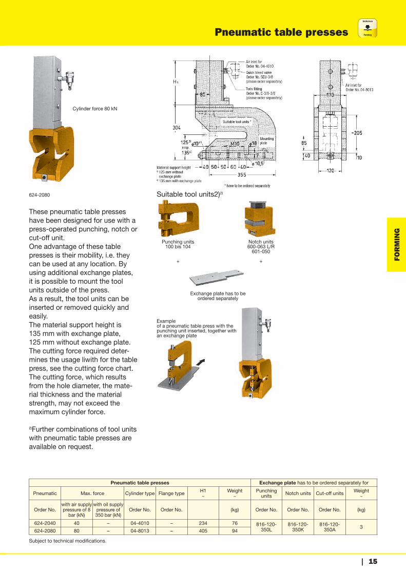
Pneumatic table presses
FORMING
624-2080
These pneumatic table presseshave been designed for use with apress-operated punching, notch orcut-off unit.One advantage of these tablepresses is their mobility, i.e. theycan be used at any location. Byusing additional exchange plates,it is possible to mount the toolunits outside of the press.As a result, the tool units can beinserted or removed quickly andeasily.The material support height is 135 mm with exchange plate, 125 mm without exchange plate.The cutting force required deter-mines the usage liwith for the tablepress, see the cutting force chart.The cutting force, which resultsfrom the hole diameter, the mate-rial thickness and the materialstrength, may not exceed themaximum cylinder force.
2)Further combinations of tool unitswith pneumatic table presses areavailable on request.
Cylinder force 80 kN
Suitable tool units2)2)
Punching units100 bis 104
+
Notch units600-063 L/R601-050
+
Exchange plate has to beordered separately
Exampleof a pneumatic table press with thepunching unit inserted, together withan exchange plate
Pneumatic table presses Exchange plate has to be ordered separately forPneumatic Max. force Cylinder type Flange type H1
~Weight~
Punchingunits Notch units Cut-off units Weight
~
Order No.with air supplypressure of 8bar (kN)
with oil supplypressure of350 bar (kN)
Order No. Order No. (kg) Order No. Order No. Order No. (kg)
624-2040 40 – 04-4010 – 234 76 816-120-350L
816-120-350K
816-120-350A 3
624-2080 80 – 04-8013 – 405 94

Umformen
Forming
16 |
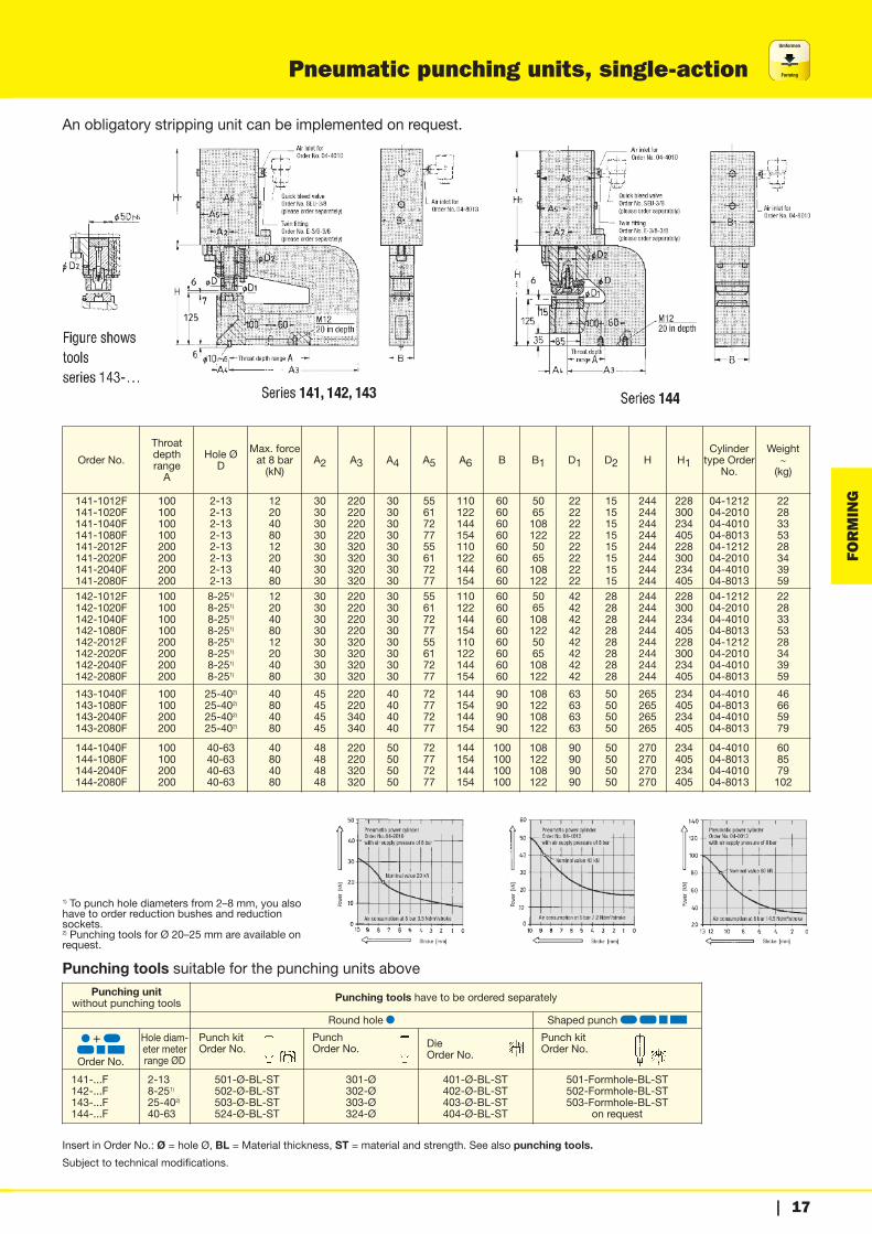
Pneumatic punching units, single-action
Subject to technical modifications.
FORMING
Driven by pneumatic power cylinder, single-action
Round and shaped cuts +Hole diameter
for series 141 2-13 mmfor series 142 8-25 mmfor series 143 25-40 mm
Only round cut Shaped cut on requestfor series 144 40-63 mm
Material thicknesswith steel 0,3-3 mm* with aluminium and plastics 0,3-5 mm**The cylinder force has to exceed the requiredcutting force.
Pneumatic punching units can beused independently from a press, asthey are driven by the powerful pneu-matic power cylinder and only needcompressed air as a power source.The pneumatic power cylinders aresingle-action; for optimum fastreversal, they additionally require a3/2 way valve, as well as a quickbleed valve; see also the illustratedconnection examples.The material support height is 125mm.The punching units should be se-lected according to the punch diame-ter, material thickness, materialstrength and the resulting cuttingforce required.The different cylinder sizes are inter-changeable, as they have the samemounting dimensions. If the cuttingforce is insufficient the next morepowerful cylinder can be used. Dou-ble-action hydraulic cylinders, includ-ing the mounting flange, can beretrofitted.The best application for pneumaticpunching units is punch work withthin metal sheets up to 3 mm thick-ness because of their progressivepower characteristic feature. With anair supply pressure of maximum 8 barthe cylinder force achieves capacitiesof 12, 20, 40 or 80 kN depending onthe cylinder type.
141-2020Cylinder force
20 kNThroat depth range A = 200 mm
142-1040 FCylinder force
40 kNThroat depth range A = 100 mm
143-1080 FCylinder force
80 kNThroat depthrange A = 100 mm
144-1080 FCylinder force
80 kNThroat depthrange A = 100 mm
Connection examples for several punching units
Subject to technical modifications.
Umformen
Forming
| 17
Pneumatic punching units, single-action
FORMING
An obligatory stripping unit can be implemented on request.
Order No.
Throatdepthrange A
Hole ØD
Max. forceat 8 bar(kN)
A2 A3 A4 A5 A6 B B1 D1 D2 H H1Cylindertype Order
No.
Weight~(kg)
141-1012F141-1020F141-1040F141-1080F141-2012F141-2020F141-2040F141-2080F
100100100100200200200200
2-132-132-132-132-132-132-132-13
1220408012204080
3030303030303030
220220220220320320320320
3030303030303030
5561727755617277
110122144154110122144154
6060606060606060
50651081225065108122
2222222222222222
1515151515151515
244244244244244244244244
228300234405228300234405
04-121204-201004-401004-801304-121204-201004-401004-8013
2228335328343959
142-1012F142-1020F142-1040F142-1080F142-2012F142-2020F142-2040F142-2080F
100100100100200200200200
8-251)8-251)8-251)8-251)8-251)8-251)8-251)8-251)
1220408012204080
3030303030303030
220220220220320320320320
3030303030303030
5561727755617277
110122144154110122144154
6060606060606060
50651081225065108122
4242424242424242
2828282828282828
244244244244244244244244
228300234405228300234405
04-121204-201004-401004-801304-121204-201004-401004-8013
2228335328343959
143-1040F143-1080F143-2040F143-2080F
100100200200
25-402)25-402)25-402)25-402)
40804080
45454545
220220340340
40404040
72777277
144154144154
90909090
108122108122
63636363
50505050
265265265265
234405234405
04-401004-801304-401004-8013
46665979
144-1040F144-1080F144-2040F144-2080F
100100200200
40-6340-6340-6340-63
40804080
48484848
220220320320
50505050
72777277
144154144154
100100100100
108122108122
90909090
50505050
270270270270
234405234405
04-401004-801304-401004-8013
608579102
Punching unitwithout punching tools Punching tools have to be ordered separately
Round hole Shaped punch
+
Order No.
Hole diam-eter meterrange ØD
Punch kit Order No.
Punch Order No. Die
Order No.
Punch kit Order No.
141-...F142-...F143-...F144-...F
2-138-251)25-402)40-63
501-Ø-BL-ST502-Ø-BL-ST503-Ø-BL-ST524-Ø-BL-ST
301-Ø302-Ø303-Ø324-Ø
401-Ø-BL-ST402-Ø-BL-ST403-Ø-BL-ST404-Ø-BL-ST
501-Formhole-BL-ST502-Formhole-BL-ST503-Formhole-BL-ST
on request
Insert in Order No.: Ø = hole Ø, BL = Material thickness, ST = material and strength. See also punching tools.
1) To punch hole diameters from 2–8 mm, you alsohave to order reduction bushes and reductionsockets.2) Punching tools for Ø 20–25 mm are available onrequest.
Punching tools suitable for the punching units above

Umformen
Forming
18 |
Hydraulic punching units, double-action
Subject to technical modifications.
FORMING
Driven byhydraulic cylinder, double-action
Round and shaped cuts +Hole diameter
for series 161 2-13 mmfor series 162 8-25 mmfor series 163 25-40 mm
Only round cut Shaped cut on requestfor series 164 40-63 mm
Material thicknesswith steel 0,3-3 mm*, max. 5 mm* with aluminium and plastics 0,3-5mm**The cylinder force has to exceed the requiredcutting force.
Hydraulic punching units, fit withdouble-action hydraulic cylindersare capable of working independ-ently from a press. They are drivenby a hydraulic power supply, e.g.an air-driven hydraulic pump, oran electrohydraulic pump unit.With the available hydraulic cylin-ders, cylinder forces of 33, 68, 109or 175 kN can be achieved for anoil supply pressure of max. 350bar. The material support height is125 mm. The punching unitsshould be selected according tothe hole diameter, material thick-ness, material strength and the resulting cutting force required.The cutting force required can beobtained from the chart.The type of power supply also de-pends on the number of punchingunits in operation and the desiredcycle time.The connection examples on theleft illustrate the operation of oneor several hydraulic punchingunits.The mounting flanges of the hydraulic cylinders have the samemounting dimensions. As a resultthe cylinder size, including themounting flange, can be exchanged if the cutting force isinsufficient.
162-1068 FCylinder force
68 kNThroat depth range A = 100 mm
162-2068 FCylinder force
68 kNThroat depth range A = 200 mm
163-1175 FCylinder force
175 kNThroat depthrange A = 100 mm
164-1175 FCylinder force
175 kNThroat depthrange A = 100 mm

Subject to technical modifications.
Umformen
Forming
| 19
Hydraulic punching units, double-action
FORMING
An obligatory stripping unit can be implemented on request.
Order No.
Throatdepthrange A
Hole ØD
Max. forceat 350 bar(kN)
A2 A3 A4 A5 B B1 D1 D2 H H1~
H2 M G
Cylinder typeincludingflange4)Order No.
Weight~(kg)
161-1033 F161-1068 F161-1109 F161-2033 F161-2068 F
100100100200200
2-132-132-132-132-13
33681093368
3030303030
220220220320320
3030303030
5860665860
6060606060
60801006080
2222222222
1515151515
244244244244244
165151158165151
4040484040
M48x1,5M64x1,5M80X2,0M48x1,5M64x1,5
G1/4G1/4G1/4G1/4G1/4
725D35151-FL725D50151-FL725D63171-FL725D35151-FL725D50151-FL
2123262729
162-1033 F162-1068 F162-1109 F162-2033 F162-2068 F
100100100200200
8-251)8-251)8-251)8-251)8-251)
33681093368
3030303030
220220220320320
3030303030
5860665860
6060606060
60801006080
4242424242
2828282828
244244244244244
165151158165151
4040484040
M48x1,5M64x1,5M80X2,0M48x1,5M64x1,5
G1/4G1/4G1/4G1/4G1/4
725D35151-FL725D50151-FL725D63171-FL725D35151-FL725D50151-FL
2123262729
163-1033 F163-1068 F163-1109 F163-1175 F163-2033 F163-2068 F163-2109 F
100100100100200200200
25-402)25-402)25-402)25-402)25-402)25-402)25-402)
33681091753368109
45454545454545
220220220220340340340
40404040404040
58606666585866
90909090909090
60801001056080100
63636363636363
50505050505050
265265265265265265265
170156161195170156161
40404848404048
M48x1,5M64x1,5M80x2,0M80x2,0M48x1,5M64x1,5M80x2,0
G1/4G1/4G1/4G3/8G1/4G1/4G1/4
725D35151-FL725D50151-FL725D63171-FL725D80151-FL725D35151-FL725D50151-FL725D63171-FL
34363945474952
164-1109 F164-1175 F164-2109 F164-2175 F
100100200200
40-6340-6340-6340-63
109175109175
48484848
220220320320
48484848
58665866
100100100100
100105100105
90909090
50505050
270270270270
169195169195
48484848
M80X2,0M80X2,0M80X2,0M80x2,0
G1/4G3/8G1/4G3/8
725D63171-FL725D80151-FL725D63171-FL725D80151-FL
49556873
Punching unitwithout punching tools Punching tools have to be ordered separately
Round hole Shaped punch
+
Order No.
Hole diam-eter meterrange ØD
Punch kit Order No.
Punch Order No. Die
Order No.
Punch kit Order No.
161-...F162-...F163-...F164-...F
2-138-251)25-402)40-63
501-Ø-BL-ST502-Ø-BL-ST503-Ø-BL-ST524-Ø-BL-ST
301-Ø302-Ø303-Ø324-Ø
401-Ø-BL-ST402-Ø-BL-ST403-Ø-BL-ST404-Ø-BL-ST
501-Formhole-BL-ST502-Formhole-BL-ST503-Formhole-BL-ST
on request
Insert in Order No.: Ø = hole Ø, BL = Material thickness, ST = material and strength. See also punching tools.
1) To punch hole diameters from 2–8 mm, you also have to order reduction bushes and reduction sockets.2) Punching tools for Ø 20–25 mm are available on request.4) If you require the cylinder without the mounting flange, owith the letters »FL« in the order no..
Punching tools suitable for the punching units above

Umformen
Forming
20 |
Pneumatic profile punching units, single-action
Subject to technical modifications.
FORMING
umatic profile punching units, single-action – without punching tools
Insert in Order No.: Ø = hole Ø, BL = Material thickness, ST = material and strength. See also punching tools.
Punching tools suitable for the punching units above
4)An obligatory stripping unit can be implemented on request. Order example: 141Z-07…
Order No. HoleØD
Throat depth rangeA
Max. forcewith air supply
pressure of 8 bar (kN)
Cylindertype4)
Order No.ØD2 A2 A3 A4 A5 A6 B1 B2 B3 G H1
Weight~(kg)
141-0712F-01141-0720F-01141-0740F-01
2-132-132-13
636363
122040
04-121204-201004-4010
151515
151515
555555
200200200
556072
110120147
6060108
545454
454545
1xG1/41xG3/81xG3/8
430502436
192430
142-0720F-01142-0740F-01142-0780F-01
8-258-258-25
636363
204080
04-201004-401004-8013
282828
262626
666666
211211211
607277
120147154
60108122
707070
707070
1xG3/81xG3/81xG3/8
502436607
323759
Punching unitwithout punching tools Punching tools have to be ordered separately
Round hole Shaped punch
+
Order No.
Hole diam-eter meterrange ØD
Punch kit Order No.
Punch Order No. Die
Order No.
Punch kit Order No.
141-...F142-...F
2-138-25
501-Ø-BL-ST502-Ø-BL-ST
301-Ø302-Ø
401-Ø-BL-ST402-Ø-BL-ST
501-Formhole-BL-ST502-Formhole-BL-ST

Subject to technical modifications.
Umformen
Forming
| 21
Hydraulic profile punching units, double-action
FORMING
Order No. HoleØD
Throat depth rangeA
Max. forcewith air supply
pressure of 500 bar (kN)
Cylinder type4)Order No. ØD2 A2 A4 A6 B1 B2 B3 G H1
Weight~(kg)
161-0724F-01161-0740F-01161-0763F-01
2-132-132-13
636363
244063
722D25202-FL 4)
722D32252-FL 4)
722D40252-FL 4)
151515
151515
200200200
657585
455563
606060
454545
2xG1/42xG1/42xG1/4
322339340
161819
162-0724F-01162-0740F-01162-0763F-01
8-258-258-25
636363
244063
722D25202-FL 4)
722D32252-FL 4)
722D40252-FL 4)
282828
262626
211211211
657585
455563
707070
707070
2xG1/42xG1/42xG1/4
317339340
242526
Hydraulic profile punching units, double action – without punching tools
Punching unitwithout punching tools Punching tools have to be ordered separately
Round hole Shaped punch
+
Order No.
Hole diam-eter meterrange ØD
Punch kit Order No.
Punch Order No. Die
Order No.
Punch kit Order No.
161-...F162-...F
2-138-25
501-Ø-BL-ST502-Ø-BL-ST
301-Ø302-Ø
401-Ø-BL-ST402-Ø-BL-ST
501-Formhole-BL-ST502-Formhole-BL-ST
Insert in Order No.: Ø = hole Ø, BL = Material thickness, ST = material and strength. See also punching tools.
Punching tools suitable for the punching units above
4) If you require the cylinder without the mounting flange, owith the letters »FL« in the order no. An obligatory stripping unit can be implemented on request.

Umformen
Forming
22 |
Pneumatic profile punching units, single-action
Subject to technical modifications.
FORMING
Order No. HoleØD
Throat depth rangeA
Max. forcewith air supply
pressure of 8 bar (kN)
Cylinder typeOrder No. ØD2 A2 A3 A4 A5 A6 B1 B2 G H1 ~
141-0812F-01141-0820F-01141-0840F-01
2-132-132-13
636363
122040
04-121204-201004-4010
151515
151515
303030
200200200
556072
110120147
6060108
454545
1xG1/41xG3/81xG3/8
472544478
141-0812F-02141-0820F-02141-0840F-02
2-132-132-13
636363
122040
04-121204-201004-4010
151515
151515
303030
200200200
556072
110120147
6060108
454545
1xG1/41xG3/81xG3/8
472544478
142-0820F-01142-0840F-01142-0880F-01
8-258-258-25
636363
204080
04-201004-401004-8013
282828
252525
505050
210210210
607277
120139154
60108122
707070
1xG3/81xG3/81xG3/8
544478649
142-0820F-02142-0840F-02142-0880F-02
8-258-258-25
636363
204080
04-201004-401004-8013
282828
252525
505050
210210210
607277
120139154
60108122
707070
1xG3/81xG3/81xG3/8
544478649
Pneumatic profile punching units, single-action – without punching tools
Punching unitwithout punching tools Punching tools have to be ordered separately
Round hole Shaped punch
+
Order No.
Hole diam-eter meterrange ØD
Punch kit Order No.
Punch Order No. Die
Order No.
Punch kit Order No.
141-...F142-...F
2-138-25
501-Ø-BL-ST502-Ø-BL-ST
301-Ø302-Ø
401-Ø-BL-ST402-Ø-BL-ST
501-Formhole-BL-ST502-Formhole-BL-ST
Insert in Order No.: Ø = hole Ø, BL = Material thickness, ST = material and strength. See also punching tools.
Punching tools suitable for the punching units above
An obligatory stripping unit can be implemented on request. Order example: 141Z-08 ...

Subject to technical modifications.
Umformen
Forming
| 23
Hydraulic profile punching units, double-action
FORMING
Order No. HoleØD
Throat depth rangeA
Max. force Cylinder typeflange4)for
combinationOrder No.
ØD2 A2 A3 A4 A6 B1 B2 G H1Weight~(kg)
with oil sup-ply pressureof 350 bar(kN)
with oil sup-ply pressureof 500 bar(kN)
161-0824F-01161-0840F-01161-0863F-01
2-132-132-13
636363
---
244063
722D25202-FL 4)722D32252-FL 4)722D40252-FL 4)
151515
151515
303030
200200200
657585
456070
454545
2xG1/42xG1/42xG1/4
364381382
282021
161-0824F-02161-0840F-02161-0863F-02
2-132-132-13
636363
---
244063
722D25202-FL 4)722D32252-FL 4)722D40252-FL 4)
151515
151515
303030
200200200
657585
456070
454545
2xG1/42xG1/42xG1/4
364381382
182021
162-08068F-01162-08109F-01162-08175F-01
8-258-258-25
636363
68109175
---
725D50151-FL 4)725D63171-FL 4)725D80151-FL 4)
282828
252525
505050
210210210
Ø65Ø97Ø105
80100100
707070
2xG1/42xG1/42xG3/8
405405440
313441
162-08068F-02162-08109F-02162-08175F-02
8-258-258-25
636363
68109175
---
725D50151-FL 4)725D63171-FL 4)725D80151-FL 4)
282828
252525
505050
210210210
Ø65Ø97Ø105
80100100
707070
2xG1/42xG1/42xG3/8
405405440
313441
Hydraulic profile punching units – without punching tools
Punching unitwithout punching tools Punching tools have to be ordered separately
Round hole Shaped punch
+
Order No.
Hole diam-eter meterrange ØD
Punch kit Order No.
Punch Order No. Die
Order No.
Punch kit Order No.
161-...F162-...F
2-138-25
501-Ø-BL-ST502-Ø-BL-ST
301-Ø302-Ø
401-Ø-BL-ST402-Ø-BL-ST
501-Formhole-BL-ST502-Formhole-BL-ST
Insert in Order No.: Ø = hole Ø, BL = Material thickness, ST = material and strength. See also punching tools.
Punching tools suitable for the punching units above
4) If you require the cylinder without the mounting flange, owith the letters »FL« in the Order No. An obligatory stripping unit can be implemented on request.Order example: 161Z-08 ...

Umformen
Forming
24 |
Pneumatic and hydraulic 90°-notch units, 63x63 mm
Subject to technical modifications.
FORMING
Driven bypneumatic power cylinder, single-action, hydraulic cylinder,double-action
Cutting angle 90°Max. notch size 63x63 mmMaterial thickness with steel 0,3–3 mm*with aluminium and plastics 0,3–5 mm*
*The cylinder force has to exceed the requiredcutting force.
Examples
660-063-068 RCylinder force 68 kN
640-063-040 RCylinder force 40 kN 2)Combination of cylinder and flange
Notch units with cutting tools
Notch size
Max. force Cylinder typeWeight~(kg)
Gauging table,adjustable,please orderseparately
Order No.
Height compen-sation plate,please orderseparatelyOrder No.
pneumatic
Order No.
hydraulic double-actionOrder No.
with air supplypressure of 8 bar (kN)
with air supplypressure of 350 bar (kN)
Flange typeOrder No.
640-063-040 L640-063-040 R
–– 63x63 40 –
04-4010-052)23
800-063 S 815-063F004-0018-0000
––
660-063-068 L660-063-068 R 63x63 – 68
725D50151-121
F004-0019-0000
In addition to the extremely successful press-operated 90° notch unitswith a notch size of 63 x 63 mm, the corresponding notch units withpneumatic and hydraulic operation are presented on this page. Liwithson the use of these units are determined by the cutting force required.The cutting force, which results from the effective cut length and thematerial thickness, may not exceed the maximum power of the cylin-der.The material support height is 85 mm.To combine these notch units with other pneumatic or hydraulicpunching it is necessary to install a height compensation plate (seechart) to reach the material support height of 125 mm.

Subject to technical modifications.
Umformen
Forming
| 25
Pneumatic and hydraulic rectangle notch units
FORMING
Driven bypneumatic power cylinder, single-action, hydraulic cylinder,double-action
Notch shape rectanglefor 641-050…, 661-050-… 50x50 mmfor 641-050…, 661-100-… 100x75 mmMaterial thickness 0,3–3 mm*
*The cylinder force has to exceed the requiredcutting force.
Examples
661-100-109Cylinder force 109 kN
641-050-040Cylinder force 40kN In addition to the extremely successful press-operated rectangle
notch units with a notch size of 50 x 50 mm and 100 x 75 mm, the corresponding notch units with pneumatic and hydraulic operation arepresented on this page.Liwiths on the use of these units are determined by the cutting force required, see chart. The cutting force, which results from the effectivecut length and the material thickness, may not exceed the maximumpower of the cylinder.The material support height is 85 mm.To combine these notch units with other pneumatic or hydraulicpunching units it is necessary to install a height compensation plate(see chart) to reach the material support height of 125 mm. For the dimensions of the basic structure, see drawing for units 601 – 050 or601 – 100.
Notch unitswith cutting tools
Notch sizeWidth x depth
Max. force Cylinder type2)Combinationof cylinderand flangeOrder No.
Cylinder dimensionsWeight~(kg)
Heightcompensa-tion plate,pleaseorder
separatelyOrder No.
pneumaticOrder No.
hydraulic double-actionOrder No.
with air supplypressure of 8bar (kN)
with oil supplypressure of 350
bar (kN)A A5 B ØD H1
~ H2~
H3~
641-050-040 – 50x50 40 – 04-4010-062) 144 72 108 – 234 20 165 32 815-050
641-100-040641-100-080
––
100x75100x75
4080
––
04-401004-8013
144154
7277
108122
––
234405
4040
182182
3963 815-100
––
661-050-068661-100-109
50x50100x75
––
68109
725D50151-1725D63171-1
––
––
––
6597
174189
2040
165182
2337
815-050815-100

Umformen
Forming
26 |
Pneumatic and hydraulic 90° radii cutting units, R5-30mm
Subject to technical modifications.
FORMING
Driven bypneumatic power cylinder, single-action hydraulic cylinder,double-action
possible radii R 5,10,15,20,25,30 mm cutting angle � 90°Material thicknesswith steel 0,3–3 mm*with aluminium and plastics 0,3–5 mm*
*The cylinder force has to exceed the requiredcutting force.
Examples
666-30-063Cylinder force 63 kN
646-30-040Cylinder force 40 kN
In addition to the press-operated radii cutting units, the correspondinghydraulic or pneumatic units are presented on this page.With these units it is possible to notch 6 different 90° radii with onlyone tool. The radii are graduated in steps of 5 mm from R 5 mm up toR 30 mm.Liwiths on the use of these units are determined by the cutting forcerequired, see chart. The cutting force, which results from the effectivecut length and the material strength, may not exceed the maximumpower of the cylinder.The material support height is 125 mm.Recommended accessories (please order separately)For connecting the pneumatic radii cutting units to the compressed airsystem, we recommend the following accessories:Other radii sizes are available on request.
Radii cutting unitswith cutting tools Possible
90° radiiin steps of 5 mm
Max. forceCylindertype
Order No.H
Weight~(kg)
pneumaticOrder No.
hydraulic double-acionOrder No.
with air supplypressure of 8bar (kN)
with oil supplypressure of 350
bar (kN)
646-30-040646-30-080
–
––
666-30-063
R5, R10, R15, R20,R25, R30
4080–
––63
04-401004-8013
722050252-1
504675375
587945

Subject to technical modifications.
Umformen
Forming
| 27
Pneumatic cut-off unit, 125 mm
FORMING
649-125-040NCylinder force 40 kN
Driven bypneumatic power cylinder, single-action
max. cutting width 125 mmMaterial thicknesswith steel 0,3–3 mm*with aluminium and plastics 0,3–5 mm*
*The cylinder force has to exceed the requiredcutting force.
In addition to the extremely suc-cessful press-operated cut-offunits with a cutting width of 125mm, the corresponding cut-off unitwith pneumatic operation is pre-sented on this page.The cutting force, which resultsfrom the effective cut length andthe material strength,may not ex-ceed the maximum power of thecylinder.The material support height is 85mm.To combine this cut-off unit withother pneumatic punching units itis necessary to install a heightcompensation plate (see chart) toreach the material support heightof 125 mm. For the dimensionsof the basic structure, see draw-ing for unit 610 – 125 N.
The retainer has been removed in the illustration!
Cut-off unitwith cutting toolswith retainerpneumaticOrder No.
Cuttingwidth
Max. force with air supply
pressure of 8 bar(kN)
Cylinder type2) Combination ofcylinder and flange
(kN)
Weight(kg)
Height compensation
plate please orderseparately Order No.
649-125-040-N 125 40 04-4010-032) 32 815-125

Umformen
Forming
28 |
Punching tools
Subject to technical modifications.
FORMING
Round hole punching tools · technical illustration of punches and dies
View »X«
Punch shape for punching units of series100, 101, 102, 111, 141,
142, 161, 162
Punch shape for punching units of series103, 104, 143, 163
Punch shape for punching units ofseries 105
Punch shape for punching units of series
112 and 113
Punch shape for punching units of series 144 and 164
Punch shape for punching units of series 114
Die shape applies to all series
� � �
� � �
�

Subject to technical modifications.
Umformen
Forming
| 29
Punching tools
FORMING
Round hole punching toolsThe required die clearance is preset in the factory in accordance with the desired hole size,while consideringthe specifiedmaterial thickness and material strength.By using reduction bushes and sockets holes can be punched with a smaller hole diameter than specified forthe particular series for some of the punching units.Punching units for round cuts can easily and quickly be converted to shaped hole punching units, using ashaped cut conversion kit.
Order exampleRound hole punching tool for punching unit order no. 102-200F
Punch kit 502 Ø 15 BL3 St42 Punch and die Punch without die 302 Ø 15 Die witout punch 402 Ø 15 BL3 St42Nominal size Hole diameter = 15 mm Material thickness BL = 3 mm Material and strength ST = St42
(for nonferrous material, e.g.: Al F22)
forpunching units
of seriesPunch kit
Sizes on stock
Punch DieAvailable hole diameters
Dimensions
Drawings on the left
Correspon-ding
drawingspage before
Order No. Order No. Order No. RangeØD
Graduation[mm] ØD2 L ØD1 H
100- 500-Ø-BL-ST 300-Ø 400-Ø-BL-ST 2-7 0,5 8 105 15 16
� + �101-111-141-161-
501-Ø-BL-ST 301-Ø 401-Ø-BL-ST 2-13 0,5 15 105 22 20
102-142-162-
502-Ø-BL-ST 302-Ø 402-Ø-BL-ST 8-25 1 28 105 42 20
103-143-163-
503-Ø-BL-ST 303-Ø 403-Ø-BL-ST25-40
special size 20-25
available
1 30 45 63 25� + �
104- 504-Ø-BL-ST 304-Ø 404-Ø-BL-ST 40-63only hole Ø 40, 42,
45, 50, 55, 60, 63 50 45 90 25
105- 505-Ø-BL-ST 305-Ø 405-Ø-BL-ST 63-100all sizes available
as special size
63 bis100
22 145 25 � + �
112- 512-Ø-BL-ST 312-Ø 402-Ø-BL-ST 8-22 1 25 80 42 20� + �
113- 513-Ø-BL-ST 313-Ø 403-Ø-BL-ST 22-38 1 40 80 63 25
114- 514-Ø-BL-ST 314-Ø 404-Ø-BL-ST 35-63all sizes available
as special size
63 80 90 25 � + �144-164- 5024-Ø-BL-ST 324-Ø 404-Ø-BL-ST 40-63 50 24 90 25 � + �
Round hole punching tools · punch kits, punches, dies, sizes on stock
Special sizes are available for each size within the diameter range

Umformen
Forming
30 |
Punching tools
Subject to technical modifications.
FORMING
Shaped hole punching tools · punch kits, sizes on stock and special sizes
View »X«
Punch shape for punching units of series100, 101, 102, 111, 141,
142, 161, 162
Punch shape for punching units of
series 103, 104, 143, 163
Punch shape for punching units ofseries 105
Punch shape for punching units of series
112 and 113
Shaped hole punching tools for series 144 and 164 are available only on request.
Punch shape for punching units ofseries 114
Die shape applies to all series
� � �
� � �
�

Subject to technical modifications.
Umformen
Forming
| 31
Punching tools
FORMING
Shaped hole punching toolsThe max. outside profile of a shaped cut may not exceed the max. possible hole diameter.The required die clearance for the die is preset in accordancewith the desired hole size,while considering thespecified material thickness and material strength.Shaped hole punching tools can be used »lengthways« or »crosswise« to the punching unit.
Order exampleShaped hole punching tool »DSW-Form« (means DAF shape, with D = diameter andAF = width across flat) as special size for punching unit order no. 103-200 F
Punch kit, punch and die 503 DSW-Form Ø30 x SW20 BL4 St60Nominal size Cutting shape Dimensions, hole diameter = 30 mm SW = 20 mm Material thickness BL = 4 mm Material and strength ST = St60
(for nonferrous material, e.g.: Al F22)
forpunching units
of series
Sizes on stock Special sizes
Range DimensionsDrawings on the left
Correspon-ding
drawings page before
Shaped cutconversion kitonly for punch-ing units whichhave been
ordered withoutshaped cut conversion kit
Order No. Order No. ØD ØD2 L ØD1 H Order No.
100- – – 2-7 – – – – – –
101-111-141-161-
501-Langloch-4,5x10-BL-ST501-Langloch-5,5x12-BL-ST501-Langloch-7x12-BL-ST
501-Langloch-a x b-BL-ST501-DSW-Form-DxSW-BL-ST501-Quadrat-a x a-BL-ST501-Rechteck-a x b-BL-ST
2-13 15 105 22 20
� + �
805-101805-111805-141805-161
102-142-162-
502-Langloch-5,5x20-BL-ST502-Langloch-7x20-BL-ST502-Langloch-9x22-BL-ST502-Langloch-11x25-BL-ST502-Langloch-13x25-BL-ST
502-Langloch-a x b-BL-ST502-DSW-Form-DxSW-BL-ST502-Quadrat-a x a-BL-ST502-Rechteck-a x b-BL-ST
8-25 28 105 42 20805-102805-142805-162
103-143-163-
–
503-Langloch-a x b-BL-ST503-DSW-Form-DxSW-BL-ST503-Quadrat-a x a-BL-ST503-Rechteck-a x b-BL-ST
20-40 50 105 63 25
� + �
805-103805-143805-163
104- –
504-Langloch-a x b-BL-ST504-DSW-Form-DxSW-BL-ST504-Quadrat-a x a-BL-ST504-Rechteck-a x b-BL-ST
40-63 75 105 90 25 805-104
105- –
505-Langloch-a x b-BL-ST505-DSW-Form-DxSW-BL-ST505-Quadrat-a x a-BL-ST505-Rechteck-a x b-BL-ST
63-10063bis100
22 145 25 � + � 805-105
112-
512-Langloch-7x20-BL-ST512-Langloch-9x22-BL-ST512-Langloch-11x22-BL-ST512-Langloch-13x22-BL-ST
512-Langloch-a x b-BL-ST512-DSW-Form-DxSW-BL-ST512-Quadrat-a x a-BL-ST512-Rechteck-a x b-BL-ST
8-22 25 80 42 20
� + �805-112
113- –
513-Langloch-a x b-BL-ST513-DSW-Form-DxSW-BL-ST513-Quadrat-a x a-BL-ST513-Rechteck-a x b-BL-ST
22-38 40 80 63 25 805-113
114- –
514-Langloch-a x b-BL-ST514-DSW-Form-DxSW-BL-ST514-Quadrat-a x a-BL-ST514-Rechteck-a x b-BL-ST
35-63 63 80 90 25 � + � 805-114
Shaped hole punching tools · punch kits, sizes on stock and special sizes
Umformen
Forming
32 |
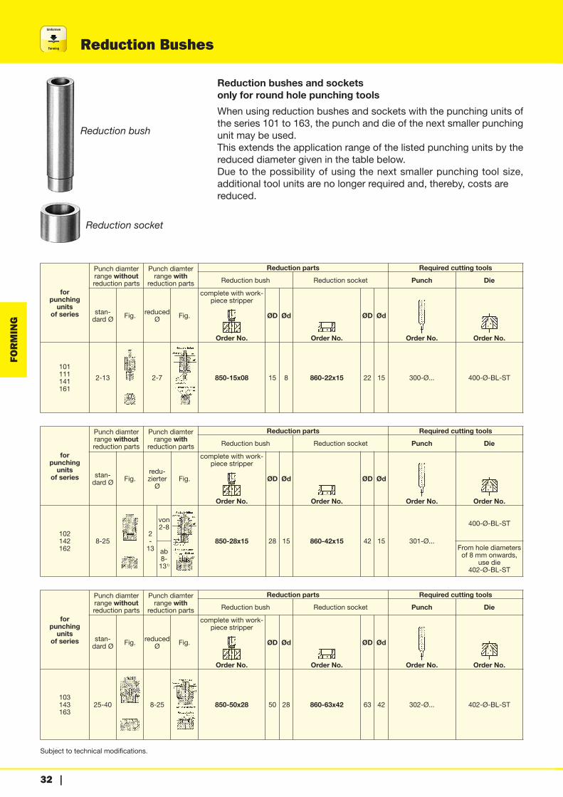
Reduction Bushes
Subject to technical modifications.
FORMING
Reduction bush
Reduction socket
Reduction bushes and socketsonly for round hole punching toolsWhen using reduction bushes and sockets with the punching units ofthe series 101 to 163, the punch and die of the next smaller punchingunit may be used.This extends the application range of the listed punching units by thereduced diameter given in the table below.Due to the possibility of using the next smaller punching tool size, additional tool units are no longer required and, thereby, costs arereduced.
forpunchingunits
of series
Punch diamterrange withoutreduction parts
Punch diamterrange with
reduction parts
Reduction parts Required cutting tools
Reduction bush Reduction socket Punch Die
stan-dard Ø Fig. reduced
Ø Fig.
complete with work-piece stripper
Order No.
ØD Ød
Order No.
ØD Ød
Order No. Order No.
101111141161
2-13 2-7 850-15x08 15 8 860-22x15 22 15 300-Ø... 400-Ø-BL-ST
forpunchingunits
of series
Punch diamterrange withoutreduction parts
Punch diamterrange with
reduction parts
Reduction parts Required cutting tools
Reduction bush Reduction socket Punch Die
stan-dard Ø Fig.
redu-zierterØ
Fig.
complete with work-piece stripper
Order No.
ØD Ød
Order No.
ØD Ød
Order No. Order No.
102142162
8-252-13
von 2-8
850-28x15 28 15 860-42x15 42 15 301-Ø...
400-Ø-BL-ST
ab 8-131)
From hole diametersof 8 mm onwards,
use die402-Ø-BL-ST
forpunchingunits
of series
Punch diamterrange withoutreduction parts
Punch diamterrange with
reduction parts
Reduction parts Required cutting tools
Reduction bush Reduction socket Punch Die
stan-dard Ø Fig. reduced
Ø Fig.
complete with work-piece stripper
Order No.
ØD Ød
Order No.
ØD Ød
Order No. Order No.
103143163
25-40 8-25 850-50x28 50 28 860-63x42 63 42 302-Ø... 402-Ø-BL-ST

Subject to technical modifications.
Umformen
Forming
| 33
Accessories
FORMING
� �
�
�
�
�for all dies
Shaped cut conversion kitsAll punching units for round cuts (except for series100) can easily and quickly be converted to shapedhole punching units, using a shaped cut conversionkit.A shaped cut torsion lock is included in the standarddelivery of all punching units (except for series 100).
for punching unit series Corresponding figures Order No.
101 � + � 805-101
102 � + � 805-102
103 � + � 805-103
104 � + � 805-104
105 � + � 805-105
111 � + � 805-111
112 � + � 805-112
113 � + � 805-113
114 � + � 805-114
141 � + � 805-141
142 � + � 805-142
143 � + � 805-143
161 � + � 805-161
162 � + � 805-162
163 � + � 805-163
Compensating washersCompensating washers are required to bring reworkeddies to the working or material support height of 85 or125 mm.This height compensation is particularly importantwhen several punching units are to be combined to aseries punch installation. In this case, uniform workingand material support height is essential.
Ødfor dies 1 kit =
4 piecesthickness
Order No.
Series to be used for punching of series
15 400 1000,10,30,51,0mm
806-15
22 401 101, 111, 141, 161 806-22
42 402, 412 102, 112, 142, 162 806-42
63 403, 413 103, 113, 143, 163 806-63
90 404, 414 104, 114 806-90
Umformen
Forming
34 |
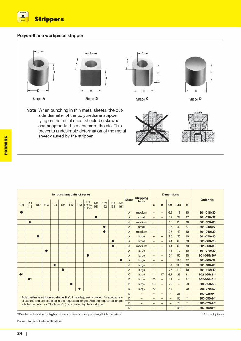
Strippers
Subject to technical modifications.
FORMING
Polyurethane workpiece stripper
Note When punching in thin metal sheets, the out-side diameter of the polyurethane stripperlying on the metal sheet should be skewedand adapted to the diameter of the die. Thisprevents undesirable deformation of the metalsheet caused by the stripper.
for punching units of series
Shape Strippingforce
Dimensions
Order No.
100 101111 102 103 104 105 112 113
1141 Satz=2 Stück
141161
142162
143163
144164 a b Ød ØD H
� A medium – – 6,5 18 30 801-018x30
� A small – – 12 28 27 801-028x27
� A medium – – 12 28 30 801-028x30
� A small – – 25 40 27 801-040x27
� A medium – – 25 40 30 801-040x30
� A large – – 25 50 30 801-050x30
� A small – – 41 60 28 801-060x28
� A medium – – 41 60 30 801-060x30
� A large – – 41 70 30 801-070x30
� A large – – 64 95 30 801-095x302)
� A large – – 100 27 801-100x27
� A large – – 64 100 30 801-100x30
� A large – – 76 112 40 801-112x40
�1) C large – 17 6,5 25 31 802-025x311)
�1) B large 28 – 12 – 31 802-028x311)
� B large 50 – 29 – 50 802-050x50
� B large 70 – 45 – 50 802-070x50
* Polyurethane strippers, shape D (fullmaterial), are provided for special ap-plications and are supplied in the requested length. Add the requested length»H« to the order no. The hole (Ød) is provided by the customer.
D – – – – 28 * 803-028xH*
D – – – – 50 * 803-050xH*
D – – – – 70 * 803-070xH*
D – – – – 100 * 803-100xH*
1) Reinforced version for higher retraction forces when punching thick materials 2) 1 kit = 2 pieces
Subject to technical modifications.
Umformen
Forming
| 35
Guide elements for series punch installation
FORMING
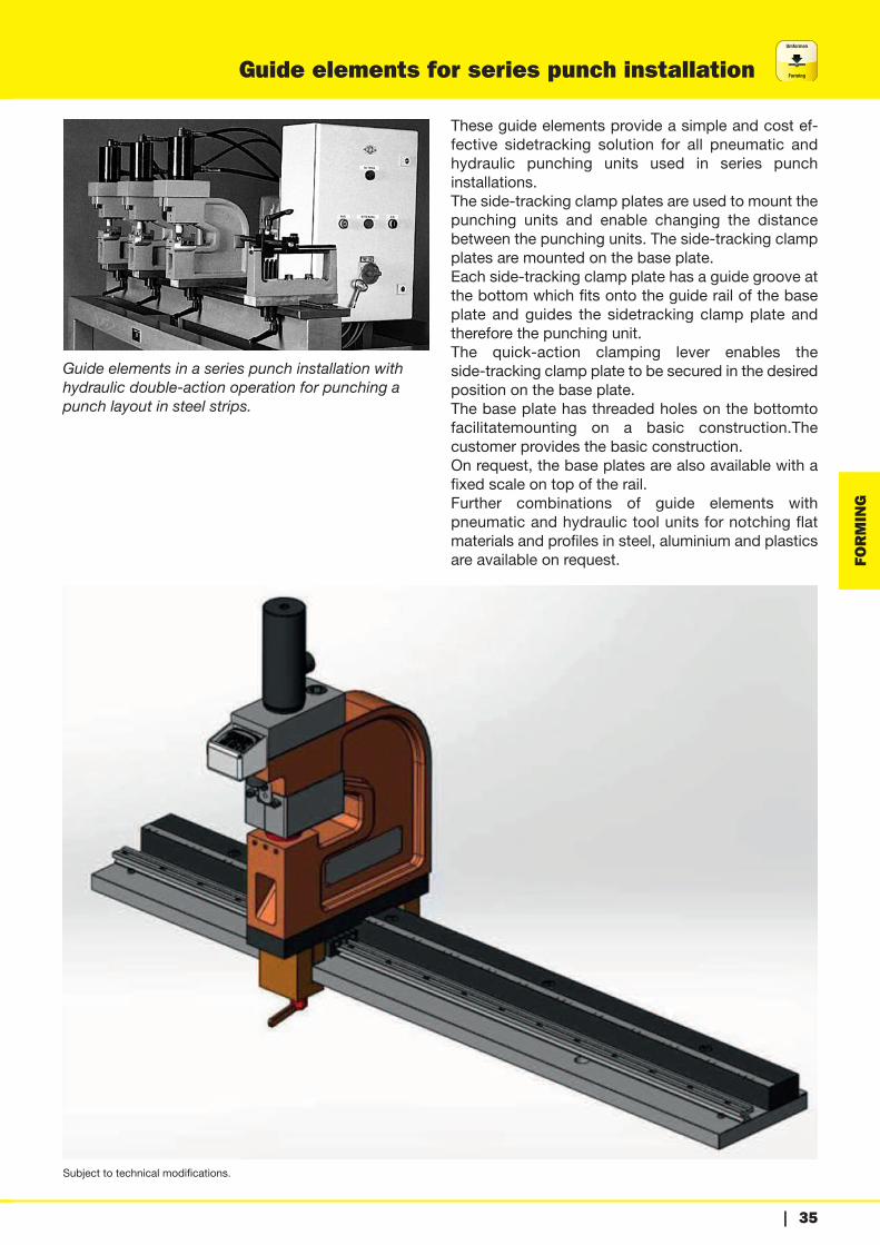
Guide elements in a series punch installation with hydraulic double-action operation for punching apunch layout in steel strips.
These guide elements provide a simple and cost ef-fective sidetracking solution for all pneumatic and hydraulic punching units used in series punch installations.The side-tracking clamp plates are used to mount thepunching units and enable changing the distance between the punching units. The side-tracking clampplates are mounted on the base plate.Each side-tracking clamp plate has a guide groove atthe bottom which fits onto the guide rail of the baseplate and guides the sidetracking clamp plate andtherefore the punching unit.The quick-action clamping lever enables the side-tracking clamp plate to be secured in the desiredposition on the base plate.The base plate has threaded holes on the bottomtofacilitatemounting on a basic construction.The customer provides the basic construction.On request, the base plates are also available with afixed scale on top of the rail.Further combinations of guide elements with pneumatic and hydraulic tool units for notching flatmaterials and profiles in steel, aluminium and plasticsare available on request.
Umformen
Forming
36 |
Guide elements for series punch installation
Subject to technical modifications.
FORMING
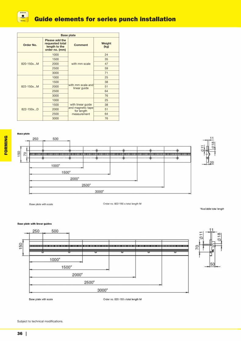
Base plate
Order No.
Please add therequested totallength to theorder no. (mm)
Comment Weight(kg)
820-150x...M
1000
with mm scale
24
1500 35
2000 47
2500 59
3000 71
822-150x...M
1000
with mm scale andlinear guide
25
1500 38
2000 51
2500 64
3000 76
822-150x...D
1000
with linear guideand magnetic tape
for length measurement
25
1500 38
2000 51
2500 64
3000 76
Subject to technical modifications.
Umformen
Forming
| 37
Guide elements for series punch installation
FORMING
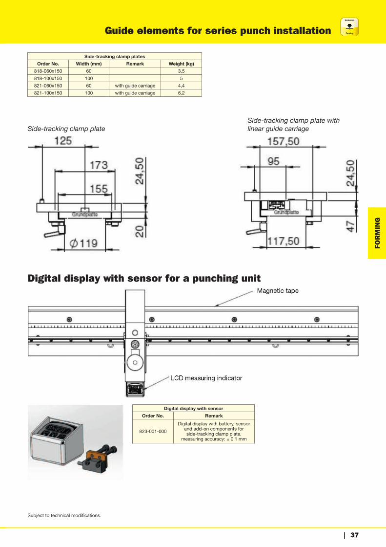
Side-tracking clamp plates
Order No. Width (mm) Remark Weight (kg)
818-060x150 60 3,5
818-100x150 100 5
821-060x150 60 with guide carriage 4,4
821-100x150 100 with guide carriage 6,2
Side-tracking clamp plate with Side-tracking clamp plate linear guide carriage
Digital display with sensor for a punching unit
Digital display with sensor
Order No. Remark
823-001-000
Digital display with battery, sensorand add-on components for side-tracking clamp plate,
measuring accuracy: ± 0.1 mm

Umformen
Forming
38 |
Frames
Subject to technical modifications.
FORMING
frame with waste collectionorder no. 820-X000-002

Subject to technical modifications.
Umformen
Forming
| 39
Frames
FORMING
Unit for punching aluminium profiles
Standard frame with waste trap, without base plate
Order No. Length Weight
820-1000-002 1000 110
820-2000-002 2000 155
820-3000-002 3000 190

Umformen
Forming
40 |
Accessories
Subject to technical modifications.
FORMING
Universal limit stop and workpiece support
Universal limit stop Workpiece support
Application examples
Support height H = 85 mm Support height H = 125 mm
A B C
Workpiece limit stopOrder No.
Workpiece supportOrder No.
Workpiece limit stopOrder No.
Workpiece supportOrder No.
800-251-085800-252-085800-253-085
810-250-085––
800-251-125800-252-125800-253-125
810-250-125––
250250250
250400630
555
800-401-085800-402-085800-403-085
810-400-085––
800-401-125800-402-125800-403-125
810-400-125––
400400400
250400630
135135135
800-631-085800-632-085800-633-085
810-630-085––
800-631-125800-632-125800-633-125
810-630-125––
630630630
250400630
255255255

Subject to technical modifications.
Umformen
Forming
| 41
Accessories
FORMING
Coordinate limit stop
Order No. 813-200x300 (also available laterally reversed)
Suitable for all pneumatic and hydraulic punchingunits with a material support height of 125 mm.For press-operated punching units with a materialsupport height of 85 mm, a height compensation plateis required (order no. 815-200x300).With the coordinate limit stops the desired distancebetween workpiece holes can be adjusted easily andquickly. Time consuming set up with conventional limitstops is unnecessary.Working range or adjustment possibilities:x-axis: 0–300 mmy-axis: 0–200 mm
Additional coordinate limit stops with other workingranges are available on request.Dimensions: 400 x 500 x 230 mm
Workpiece limit stop
Workpiece limit stop with support Workpiece limit stop
Application example
H H1 Workpiece limit stop with support Order No.
Workpiece limit stop Order No.
85–
–40
800-01-085–
–800-02-085
125–
–80
800-01-125–
–800-02-125


ARGENTINA – TÜNKERS DE ARGENTINA S.A.Velez Sarsfield 1516 – Quilmes (1879)Provincia de Buenos AiresTel.: +54 11 [email protected]–––––––––––––AUSTRALIA – Romheld Australia Pty. Ltd.30/115 Woodpark RdSmithfield N.S.W 2164Tel.: +61 2 [email protected]–––––––––––––AUSTRIA – B-S-D Spanntechnik GmbHSportplatzstrasse 313385 MarkersdorfTel.: +43 2749 [email protected]–––––––––––––BALTIC STATES – Vertriebsbüro Ost Markt 11D-07426 KönigseeTel.: +49 36738 [email protected]–––––––––––––BELGIUM – SOPAP Automation SASP. A. Ardennes EmeraudeRue Henri FaureF-BP 11 09, 08090 TOURNESTel.: +33 3 24 52 94 [email protected]–––––––––––––BRAZIL – Tünkers do Brasil Ltda.Avenida Casa Grande, 850 – Galpão 6, 11 e 13Bairro: Casa grande09961-350 – Diadema - São PauloTel.: +55 11 [email protected]–––––––––––––CANADA – TUNKERS-Mastech36200 Mound RoadSterling Heights, MI 48312Tel.: +1 734 744 [email protected]–––––––––––––CHINA – TÜNKERS ChinaTuenkers Machinery & AutomationTechnology Co., Ltd. ShanghaiBuilding 4, No. 768 Chenxiang Road,Jiading District, Shanghai P.R.China, 201802Tel.: +86 21 [email protected] Offices: Changchun, Nanjing, Chengdu, Beijing, Wuhan, Guangzhou, Yantei, Shenyang–––––––––––––CZECH REPUBLIC – Vertriebsbüro Ost Markt 11D-07426 KönigseeTel.: +49 36738 [email protected]
CZECH REPUBLIC – Kopta s. r. o.Vážní 891 / areál PSN ICZ-500 03 Hradec KrálovéTel.: +420 495 53 [email protected]–––––––––––––DENMARK – Berga Maskin64693 GnestaTel.: +46 158 [email protected]–––––––––––––FINLAND – Berga Maskin64693 GnestaTel.: +46 158 [email protected]–––––––––––––FRANCE – SOPAP Automation SASP. A. Ardennes EmeraudeRue Henri FaureBP 11 09, 08090 TOURNESTel.: +33 3 24 52 94 [email protected]–––––––––––––HUNGARY – TÜNKERS Slovakia s.r.o.Roentgenova 26SK85101 BratislavaTel.: +421 905 564 [email protected]–––––––––––––INDIA – TÜNKERS Automation India Private Ltd.402 Supreme Head Quarters 36 Mumbai-Pune Bypass411008 Baner-PuneTel.: +91 98 60 [email protected]–––––––––––––INDONESIA – DAB Technology Pte. Ltd. 21 Woodlands Industrial Park E1, #03-04Singapore 757720Tel.: +65 6891 [email protected]–––––––––––––ITALY – TÜNKERS ItaliaStrada TORINO, 43 EUROPLACE sub. 0610043 ORBASSANO-TORINOTel.: +39 011 [email protected]–––––––––––––JAPAN – TÜNKERS Japan Ltd.Daimyo Create Bldg. 6FDaimyo 1-8-20Chuo-ku, Fukuoka 810-0041 JAPANTel.: +81 80 [email protected]–––––––––––––MALAYSIA – DAB Technology Sdn.Bhd.No 9-2B Jalan Bandar 10, Pusat Bandar Puchong47100 SelangorTel.: +603 8060 [email protected]–––––––––––––
MOROCCO – SOPAP Automation SASP. A. Ardennes EmeraudeRue Henri FaureF-BP 11 09, 08090 TOURNESTel.: +33 3 24 52 94 [email protected]–––––––––––––MEXICO – TUNKERS DE MÉXIKO, S.A. DE C.V.Calle Emiliano Zapata No.17-2Col. Emiliano Zapata72810 San Andrés Cholula PueblaTel.: +52 222 393 [email protected]–––––––––––––NETHERLANDS – TÜNKERS Maschinenbau GmbHAm Rosenkothen 4-12D-40880 RatingenTel.: +49 2102 [email protected]–––––––––––––POLAND – TÜNKERS Slovakia s.r.o.Roentgenova 26SK85101 BratislavaTel.: +48 660 055 [email protected]–––––––––––––ROMANIA – TÜNKERS Maschinenbau GmbH55068 Sibiu, RomaniaTel.: +40-752 184 [email protected]–––––––––––––RUSSIA – WEST-RUNovikova-Priboya Str. 4 office 407603058 Nizhny NovgorodTel.: +7 831 253 01 65
RUSSIA – Cont GroupOffice 315, Sibirskij Proezd 2-27Moscow 109316Tel.: +7 495 775 - 0377–––––––––––––SERBIA – TÜNKERS Maschinenbau GmbH55068 Sibiu, RomaniaTel.: +40-752 184 [email protected]–––––––––––––SINGAPORE – DAB Technology Pte. Ltd.21 Woodlands Industrial Park E1#03-04Singapore 757720Tel.: +65 [email protected]–––––––––––––SLOVAKIA – TÜNKERS Slovakia s.r.o.Twin City CMlynské nivy 16SK82109 BratislavaTel.: +421 905 564 [email protected]–––––––––––––
SLOVENIA – TÜNKERS Maschinenbau GmbH55068 Sibiu, RomaniaTel.: +40-752 184 [email protected]–––––––––––––SOUTH AFRICA – Demcon (Cape) ccPO Box 15237ZA-60110 Emerald Hill/Port ElizabethTel.: +27 41 [email protected]–––––––––––––SOUTH KOREA – JC Systems Co. Ltd.#405 Ace Highend 9Cha, 233,Gasan digital 1-ro, Geumcheon-gu, SeoulTel.: +82 70 [email protected]–––––––––––––SPAIN – TÜNKERS IBÉRICA, S.L.c/ Enric Prat de la Riba, 14b08830 Sant Boi de Llobregat (Barcelona)Tel.: +34 93 [email protected]–––––––––––––SWEDEN – BERGA MASKINSE-646 93 GNESTATel.: +46 158 311 [email protected]–––––––––––––THAILAND – DAB Technology Co., Ltd.H20 424/15 Kanchanapisek Rd.Dokmai, Pravet,Bangkok 10250Tel.: +66 97 072 [email protected]–––––––––––––TURKEY – Cava MakinaImes Sanayi Sitesi E 50334776 Umraniye / IstanbulTel.: +90 216 [email protected]–––––––––––––UK – TÜNKERS-EXPERT UK Ltd.Unit 5, Ham Lane,Kingswinford,West Midlands.DY6 7JRTel.: +44 (0) 1384 [email protected]–––––––––––––USA – TUNKERS-Mastech36200 Mound RoadSterling Heights, MI 48312Tel.: +1 734 744 [email protected]–––––––––––––VIETNAM – DAB Technology Pte. Ltd.21 Woodlands Industrial Park E1#03-04Singapore 757720Tel.: +65 [email protected]–––––––––––––
–––––––––––––
At your service - worldwide
TÜNKERS Maschinenbau GmbHAm Rosenkothen 4-1240880 RatingenGermanyTel.: +49 2102 [email protected]
EXPERT-TÜNKERS GmbHSeehofstraße 56-5864653 LorschGermanyTel.: +49 6251 [email protected]
HELU GmbHSeehofstraße 56-5864653 LorschGermanyTel.: +49 6251 [email protected]
SOPAP Automation SASP. A. Ardennes EmeraudeRue Henri FaureBP 11 09, 08090 TOURNESFranceTel.: +33 3 24 52 94 [email protected]