Embed Size (px)
Citation preview
Dansk standard
DS/EN 62271-102
1. udgave 2003-06-06
Højspændingskoblingsudstyr –
Del 102: Højspændingsadskillere og jordsluttere til vekselstrøm
High-voltage switchgear and controlgear – Part 102: High-voltage alternating current disconnectors and earthing switches
CO
PY
RIG
HT
© D
anis
h S
tand
ards
Fou
ndat
ion.
NO
T FO
R C
OM
ME
RC
IAL
US
E O
R R
EP
RO
DU
CTI
ON
. DS
/EN
622
71-1
02:2
003
DS-publikationstyper Dansk Standard udgiver forskellige publikationstyper. Typen på denne publikation fremgår af forsiden. Der kan være tale om: Dansk standard
• standard, der er udarbejdet på nationalt niveau eller er baseret på et andet lands nationale standard, eller • standard, der er udarbejdet på internationalt og/eller europæisk niveau og har fået status som dansk standard
DS-information • publikation, der er udarbejdet på nationalt niveau og ikke har opnået status som standard, eller • publikation, der er udarbejdet på internationalt og/eller europæisk niveau og ikke har fået status som standard, fx en
teknisk rapport, eller • europæisk præstandard DS-håndbog • samling af standarder, eventuelt suppleret med informativt materiale
DS-hæfte • publikation med informativt materiale
Til disse publikationstyper kan endvidere udgives
• tillæg og rettelsesblade DS-publikationsform Publikationstyperne udgives i forskellig form som henholdsvis
• fuldtekstpublikation (publikationen er trykt i sin helhed) • godkendelsesblad (publikationen leveres i kopi med et trykt DS-omslag) • elektronisk (publikationen leveres på et elektronisk medie)
DS-betegnelse Alle DS-publikationers betegnelse begynder med DS efterfulgt af et eller flere præfikser og et nr. fx DS 383, DS/EN 5414 osv. Hvis der efter nr. er angivet et A eller Cor, betyder det, enten at det er et tillæg eller et rettelsesblad til hovedstandarden, eller at det er indført i hovedstandarden. DS-betegnelse angives på forsiden. Overensstemmelse med anden publikation: Overensstemmelse kan enten være IDT, EQV, NEQ eller MOD
• IDT: Når publikationen er identisk med en given publikation. • EQV: Når publikationen teknisk er i overensstemmelse med en given publikation, men
præsentationen er ændret. • NEQ: Når publikationen teknisk eller præsentationsmæssigt ikke er i overensstemmelse med en
given standard, men udarbejdet på baggrund af denne. • MOD: Når publikationen er modificeret i forhold til en given publikation.
DS/EN 62271-102
København DS projekt: 42776 ICS: 29.130.10 Deskriptorer: afbrydere,jordsluttere,vekselstrøm Første del af denne publikations betegnelse er: DS/EN, hvilket betyder, at det er en europæisk standard, der har status som dansk standard. Denne publikations overensstemmelse er: IDT med: IEC 62271-102:2001+Corr.:2002 og IDT med: EN 62271-102:2002. DS-publikationen er på engelsk. Denne publikation erstatter: DS/EN 60129+A,2:1996, DS/EN 61129+A1:1995 og DS/EN 61259:1995
CO
PY
RIG
HT
© D
anis
h S
tand
ards
Fou
ndat
ion.
NO
T FO
R C
OM
ME
RC
IAL
US
E O
R R
EP
RO
DU
CTI
ON
. DS
/EN
622
71-1
02:2
003

EUROPEAN STANDARD EN 62271-102NORME EUROPÉENNE
EUROPÄISCHE NORM July 2002
CENELECEuropean Committee for Electrotechnical Standardization
Comité Européen de Normalisation ElectrotechniqueEuropäisches Komitee für Elektrotechnische Normung
Central Secretariat: rue de Stassart 35, B - 1050 Brussels
© 2002 CENELEC - All rights of exploitation in any form and by any means reserved worldwide for CENELEC members.
Ref. No. EN 62271-102:2002 E
ICS 29.130.10;29.130.99 Supersedes EN 60129:1994 + A1:1994 + A2:1996;EN 61129:1994 + A1:1995 and
EN 61259:1994
English version
High-voltage switchgear and controlgearPart 102: High-voltage alternating current
disconnectors and earthing switches(IEC 62271-102:2001 + corrigendum 2002)
Appareillage à haute tensionPartie 102: Sectionneurs et sectionneursde terre à courant alternatif haute tension(CEI 62271-102:2001+ corrigendum 2002)
Hochspannungs-SchaltgeräteTeil 102: Hochspannungs-Wechselstrom-Trennschalter und -Erdungsschalter(IEC 62271-102:2001+ Corrigendum 2002)
This European Standard was approved by CENELEC on 2002-03-05. CENELEC members are bound tocomply with the CEN/CENELEC Internal Regulations which stipulate the conditions for giving this EuropeanStandard the status of a national standard without any alteration.
Up-to-date lists and bibliographical references concerning such national standards may be obtained onapplication to the Central Secretariat or to any CENELEC member.
This European Standard exists in three official versions (English, French, German). A version in any otherlanguage made by translation under the responsibility of a CENELEC member into its own language andnotified to the Central Secretariat has the same status as the official versions.
CENELEC members are the national electrotechnical committees of Austria, Belgium, Czech Republic,Denmark, Finland, France, Germany, Greece, Hungary, Iceland, Ireland, Italy, Luxembourg, Malta,Netherlands, Norway, Portugal, Slovakia, Spain, Sweden, Switzerland and United Kingdom.
CO
PY
RIG
HT
© D
anis
h S
tand
ards
Fou
ndat
ion.
NO
T FO
R C
OM
ME
RC
IAL
US
E O
R R
EP
RO
DU
CTI
ON
. DS
/EN
622
71-1
02:2
003
EN 62271-102:2002 - 2 -
Foreword
The text of document 17A/617/FDIS, future edition 1 of IEC 62271-102, prepared by SC 17A, High-voltageswitchgear and controlgear, of IEC TC 17, Switchgear and controlgear, was submitted to the IEC-CENELEC parallel vote and was approved by CENELEC as EN 62271-102 on 2002-03-05.
This European Standard supersedes the European Standards EN 60129:1994 + A1:1994 + A2:1996 ,EN 61129:1994 + A1:1995 and EN 61259:1994.
The following dates were fixed:
– latest date by which the EN has to be implementedat national level by publication of an identicalnational standard or by endorsement (dop) 2003-02-01
– latest date by which the national standards conflictingwith the EN have to be withdrawn (dow) 2005-03-01
This European Standard is to be used in conjunction with EN 60694:1996 to which it refers and which isapplicable, unless otherwise specified. In order to simplify the indication of corresponding requirements,the same numbering of clauses and subclauses is used as in EN 60694. Additional subclauses arenumbered from 101.
Annexes designated "normative" are part of the body of the standard.Annexes designated "informative" are given for information only.In this standard, annexes A, B, C, E, F and ZA are normative and annex D is informative.Annex ZA has been added by CENELEC.
The numbering of the standards falling under the responsibility of IEC/SC 17A and IEC/SC 17B will applythe following principle:
a) Common standards prepared by SC 17A and SC 17C will start with IEC 62271-001;
b) Standards of SC 17A will start with IEC 62271-100;
c) Standards of SC 17C will start with IEC 62271-200;
d) Guides prepared by SC 17A and SC 17C will start with IEC 62271-300.
CO
PY
RIG
HT
© D
anis
h S
tand
ards
Fou
ndat
ion.
NO
T FO
R C
OM
ME
RC
IAL
US
E O
R R
EP
RO
DU
CTI
ON
. DS
/EN
622
71-1
02:2
003
- 3 - EN 62271-102:2002
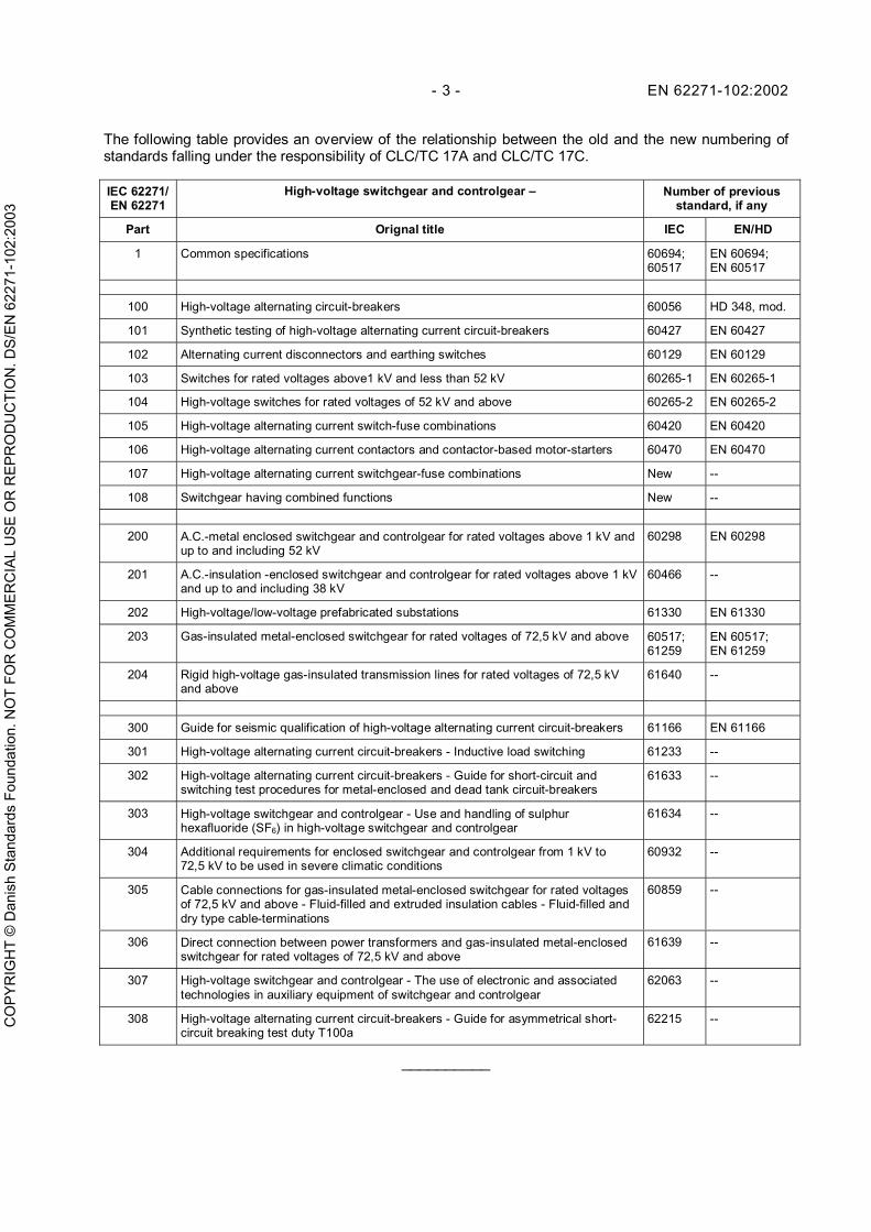
The following table provides an overview of the relationship between the old and the new numbering ofstandards falling under the responsibility of CLC/TC 17A and CLC/TC 17C.
IEC 62271/EN 62271
High-voltage switchgear and controlgear – Number of previousstandard, if any
Part Orignal title IEC EN/HD
1 Common specifications 60694;60517
EN 60694;EN 60517
100 High-voltage alternating circuit-breakers 60056 HD 348, mod.
101 Synthetic testing of high-voltage alternating current circuit-breakers 60427 EN 60427
102 Alternating current disconnectors and earthing switches 60129 EN 60129
103 Switches for rated voltages above1 kV and less than 52 kV 60265-1 EN 60265-1
104 High-voltage switches for rated voltages of 52 kV and above 60265-2 EN 60265-2
105 High-voltage alternating current switch-fuse combinations 60420 EN 60420
106 High-voltage alternating current contactors and contactor-based motor-starters 60470 EN 60470
107 High-voltage alternating current switchgear-fuse combinations New --
108 Switchgear having combined functions New --
200 A.C.-metal enclosed switchgear and controlgear for rated voltages above 1 kV andup to and including 52 kV
60298 EN 60298
201 A.C.-insulation -enclosed switchgear and controlgear for rated voltages above 1 kVand up to and including 38 kV
60466 --
202 High-voltage/low-voltage prefabricated substations 61330 EN 61330
203 Gas-insulated metal-enclosed switchgear for rated voltages of 72,5 kV and above 60517;61259
EN 60517;EN 61259
204 Rigid high-voltage gas-insulated transmission lines for rated voltages of 72,5 kVand above
61640 --
300 Guide for seismic qualification of high-voltage alternating current circuit-breakers 61166 EN 61166
301 High-voltage alternating current circuit-breakers - Inductive load switching 61233 --
302 High-voltage alternating current circuit-breakers - Guide for short-circuit andswitching test procedures for metal-enclosed and dead tank circuit-breakers
61633 --
303 High-voltage switchgear and controlgear - Use and handling of sulphurhexafluoride (SF6) in high-voltage switchgear and controlgear
61634 --
304 Additional requirements for enclosed switchgear and controlgear from 1 kV to72,5 kV to be used in severe climatic conditions
60932 --
305 Cable connections for gas-insulated metal-enclosed switchgear for rated voltagesof 72,5 kV and above - Fluid-filled and extruded insulation cables - Fluid-filled anddry type cable-terminations
60859 --
306 Direct connection between power transformers and gas-insulated metal-enclosedswitchgear for rated voltages of 72,5 kV and above
61639 --
307 High-voltage switchgear and controlgear - The use of electronic and associatedtechnologies in auxiliary equipment of switchgear and controlgear
62063 --
308 High-voltage alternating current circuit-breakers - Guide for asymmetrical short-circuit breaking test duty T100a
62215 --
__________
CO
PY
RIG
HT
© D
anis
h S
tand
ards
Fou
ndat
ion.
NO
T FO
R C
OM
ME
RC
IAL
US
E O
R R
EP
RO
DU
CTI
ON
. DS
/EN
622
71-1
02:2
003

EN 62271-102:2002 - 4 -
Endorsement notice
The text of the International Standard IEC 62271-102:2001 and its corrigendum April 2002 was approved byCENELEC as a European Standard without any modification.
__________
CO
PY
RIG
HT
© D
anis
h S
tand
ards
Fou
ndat
ion.
NO
T FO
R C
OM
ME
RC
IAL
US
E O
R R
EP
RO
DU
CTI
ON
. DS
/EN
622
71-1
02:2
003
- 5 - EN 62271-102:2002
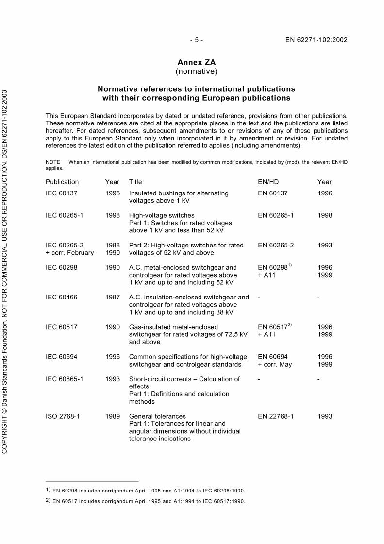
Annex ZA(normative)
Normative references to international publicationswith their corresponding European publications
This European Standard incorporates by dated or undated reference, provisions from other publications.These normative references are cited at the appropriate places in the text and the publications are listedhereafter. For dated references, subsequent amendments to or revisions of any of these publicationsapply to this European Standard only when incorporated in it by amendment or revision. For undatedreferences the latest edition of the publication referred to applies (including amendments).
NOTE When an international publication has been modified by common modifications, indicated by (mod), the relevant EN/HDapplies.
Publication Year Title EN/HD Year
IEC 60137 1995 Insulated bushings for alternatingvoltages above 1 kV
EN 60137 1996
IEC 60265-1 1998 High-voltage switchesPart 1: Switches for rated voltagesabove 1 kV and less than 52 kV
EN 60265-1 1998
IEC 60265-2+ corr. February
19881990
Part 2: High-voltage switches for ratedvoltages of 52 kV and above
EN 60265-2 1993
IEC 60298 1990 A.C. metal-enclosed switchgear andcontrolgear for rated voltages above1 kV and up to and including 52 kV
EN 602981)
+ A1119961999
IEC 60466 1987 A.C. insulation-enclosed switchgear andcontrolgear for rated voltages above1 kV and up to and including 38 kV
- -
IEC 60517 1990 Gas-insulated metal-enclosedswitchgear for rated voltages of 72,5 kVand above
EN 605172)
+ A1119961999
IEC 60694 1996 Common specifications for high-voltageswitchgear and controlgear standards
EN 60694+ corr. May
19961999
IEC 60865-1 1993 Short-circuit currents – Calculation ofeffectsPart 1: Definitions and calculationmethods
- -
ISO 2768-1 1989 General tolerancesPart 1: Tolerances for linear andangular dimensions without individualtolerance indications
EN 22768-1 1993
1) EN 60298 includes corrigendum April 1995 and A1:1994 to IEC 60298:1990.
2) EN 60517 includes corrigendum April 1995 and A1:1994 to IEC 60517:1990.
CO
PY
RIG
HT
© D
anis
h S
tand
ards
Fou
ndat
ion.
NO
T FO
R C
OM
ME
RC
IAL
US
E O
R R
EP
RO
DU
CTI
ON
. DS
/EN
622
71-1
02:2
003
CO
PY
RIG
HT
© D
anis
h S
tand
ards
Fou
ndat
ion.
NO
T FO
R C
OM
ME
RC
IAL
US
E O
R R
EP
RO
DU
CTI
ON
. DS
/EN
622
71-1
02:2
003

INTERNATIONALSTANDARD
IEC62271-102
First edition2001-12
High-voltage switchgear and controlgear –
Part 102:Alternating current disconnectorsand earthing switches
Appareillage à haute tension –
Partie 102:Sectionneurs et sectionneurs de terreà courant alternatif
Reference numberIEC 62271-102:2001(E)
CO
PY
RIG
HT
© D
anis
h S
tand
ards
Fou
ndat
ion.
NO
T FO
R C
OM
ME
RC
IAL
US
E O
R R
EP
RO
DU
CTI
ON
. DS
/EN
622
71-1
02:2
003

– 2 – 62271-102 IEC:2001(E)
CONTENTS
FOREWORD ..........................................................................................................................7
1 General .......................................................................................................................... 101.1 Scope ................................................................................................................. 101.2 Normative references ......................................................................................... 10
2 Normal and special service conditions ............................................................................ 113 Definitions ...................................................................................................................... 11
3.1 General terms..................................................................................................... 113.2 Assemblies of switchgear and controlgear .......................................................... 113.3 Parts of assemblies ............................................................................................ 113.4 Switching devices ............................................................................................... 113.5 Parts of switching devices .................................................................................. 133.6 Operation ........................................................................................................... 143.7 Characteristic quantities ..................................................................................... 15
4 Ratings........................................................................................................................... 184.1 Rated voltage (Ur) .............................................................................................. 184.2 Rated insulation level ......................................................................................... 184.3 Rated frequency (fr) ............................................................................................ 184.4 Rated normal current and temperature rise ......................................................... 184.5 Rated short-time withstand current (Ik) ............................................................... 194.6 Rated peak withstand current (Ip) ....................................................................... 194.7 Rated duration of short-circuit (tk) ....................................................................... 194.8 Rated supply voltage of closing and opening devices and of auxiliary and
control circuits (Ua)............................................................................................. 194.9 Rated supply frequency of closing and opening devices and of auxiliary
circuits................................................................................................................ 194.10 Rated pressure of compressed gas supply for insulation and/or operation .......... 194.101 Rated short-circuit making current ...................................................................... 194.102 Rated contact zone............................................................................................. 194.103 Rated mechanical terminal load .......................................................................... 204.104 Rated values of the bus-transfer current switching capability of
disconnectors ..................................................................................................... 214.105 Rated values of the induced current switching capability of earthing
switches ............................................................................................................. 214.106 Rated values of mechanical endurance for disconnectors and earthing
switches ............................................................................................................. 224.107 Rated values of electrical endurance for earthing switches ................................. 22
5 Design and construction ................................................................................................. 225.1 Requirements for liquids in disconnectors and earthing switches ........................ 225.2 Requirements for gases in disconnectors and earthing switches ......................... 225.3 Earthing of disconnectors and earthing switches................................................. 225.4 Auxiliary and control equipment .......................................................................... 225.5 Dependent power operation ................................................................................ 235.6 Stored energy operation ..................................................................................... 23
CO
PY
RIG
HT
© D
anis
h S
tand
ards
Fou
ndat
ion.
NO
T FO
R C
OM
ME
RC
IAL
US
E O
R R
EP
RO
DU
CTI
ON
. DS
/EN
622
71-1
02:2
003

62271-102 © IEC:2001(E) – 3 –
5.7 Independent manual operation............................................................................ 235.8 Operation of releases ......................................................................................... 235.9 Low- and high-pressure interlocking and monitoring devices............................... 235.10 Nameplates ........................................................................................................ 235.11 Interlocking devices ............................................................................................ 245.12 Position indication .............................................................................................. 245.13 Degree of protection by enclosures..................................................................... 245.14 Creepage distances ............................................................................................ 255.15 Gas and vacuum tightness.................................................................................. 255.16 Liquid tightness .................................................................................................. 255.17 Flammability ....................................................................................................... 255.18 Electromagnetic compatibility (EMC)................................................................... 255.101 Special requirements for earthing switches ......................................................... 255.102 Requirements in respect of the isolating distance of disconnectors ..................... 255.103 Mechanical strength............................................................................................ 265.104 Operation of disconnectors and earthing switches– Position of the movable
contact system and its indicating and signalling devices ..................................... 265.105 Maximum force required for manual operation .................................................... 275.106 Dimensional tolerances....................................................................................... 27
6 Type tests ...................................................................................................................... 276.1 General .............................................................................................................. 276.2 Dielectric tests .................................................................................................... 286.3 Radio interference voltage (riv) test .................................................................... 306.4 Measurement of the resistance of circuits ........................................................... 306.5 Temperature-rise tests........................................................................................ 316.6 Short-time withstand current and peak withstand current tests ............................ 316.7 Verification of the protection ............................................................................... 336.8 Tightness tests ................................................................................................... 336.9 Electromagnetic compatibility tests (EMC) .......................................................... 336.101 Test to prove the short-circuit making performance of earthing switches............. 336.102 Operating and mechanical endurance tests ........................................................ 346.103 Operation under severe ice conditions ................................................................ 376.104 Operation at the temperature limits ..................................................................... 396.105 Test to verify the proper functioning of the position indicating device .................. 406.106 Bus-transfer current switching tests .................................................................... 406.107 Induced current switching tests........................................................................... 406.108 Bus-charging switching tests .............................................................................. 41
7 Routine tests .................................................................................................................. 417.1 Dielectric test on the main circuit ........................................................................ 417.2 Dielectric test on auxiliary and control circuits .................................................... 417.3 Measurement of the resistance of the main circuit .............................................. 427.4 Tightness test ..................................................................................................... 427.5 Design and visual checks ................................................................................... 427.101 Mechanical operating tests ................................................................................. 42
CO
PY
RIG
HT
© D
anis
h S
tand
ards
Fou
ndat
ion.
NO
T FO
R C
OM
ME
RC
IAL
US
E O
R R
EP
RO
DU
CTI
ON
. DS
/EN
622
71-1
02:2
003
– 4 – 62271-102 IEC:2001(E)
8 Guide to the selection of disconnectors and earthing switches........................................ 428.101 General .............................................................................................................. 428.102 Selection of rated values for normal service conditions ....................................... 43
9 Information to be given with enquiries, tenders and orders ............................................. 469.101 Information to be given with enquiries and orders ............................................... 469.102 Information to be given with tenders ................................................................... 47
10 Rules for transport, storage, installation, operation and maintenance ............................. 4810.1 Conditions during transport, storage and installation........................................... 4810.2 Installation .......................................................................................................... 4910.3 Operation ........................................................................................................... 4910.4 Maintenance ....................................................................................................... 49
11 Safety............................................................................................................................. 4911.1 Electrical aspects ............................................................................................... 4911.2 Mechanical aspects ............................................................................................ 4911.3 Thermal aspects ................................................................................................. 4911.4 Operation aspects .............................................................................................. 49
Annex A (normative) Design and testing of position indicating devices................................. 56A.1 General .............................................................................................................. 56A.2 Normal and special service conditions ................................................................ 56A.3 Definitions .......................................................................................................... 56A.4 Ratings ............................................................................................................... 57A.5 Design and construction ..................................................................................... 57A.6 Type tests........................................................................................................... 57A.7 Routine tests ...................................................................................................... 60
Annex B (normative) Bus-transfer current switching by disconnectors .................................. 61B.1 General .............................................................................................................. 61B.2 Normal and special service conditions ................................................................ 61B.3 Definitions .......................................................................................................... 61B.4 Ratings ............................................................................................................... 61B.5 Design and construction ..................................................................................... 62B.6 Type tests........................................................................................................... 62
Annex C (normative) Induced current switching by earthing switches ................................... 67C.1 General .............................................................................................................. 67C.2 Normal and special service conditions ................................................................ 67C.3 Definitions .......................................................................................................... 67C.4 Ratings ............................................................................................................... 68C.5 Design and construction ..................................................................................... 69C.6 Type tests........................................................................................................... 70
CO
PY
RIG
HT
© D
anis
h S
tand
ards
Fou
ndat
ion.
NO
T FO
R C
OM
ME
RC
IAL
US
E O
R R
EP
RO
DU
CTI
ON
. DS
/EN
622
71-1
02:2
003
62271-102 © IEC:2001(E) – 5 –
Annex D (informative) Test voltage for the most disadvantageous dielectric positionof an earthing switch during operation (temporary approach) ................................................ 77
Annex E (normative) Special requirements for disconnectors and earthing switchesused in gas-insulated and/or metal-enclosed switchgear ....................................................... 78
E.1 General .............................................................................................................. 78E.2 Normal and special service conditions ................................................................ 78E.3 Definitions .......................................................................................................... 78E.4 Ratings ............................................................................................................... 79E.5 Design and construction ..................................................................................... 79E.6 Type tests........................................................................................................... 80E.7 Routine tests ...................................................................................................... 81E.8 Guide to the selection of disconnectors and earthing switches............................ 82E.9 Information to be given with enquiries, tenders and orders ................................. 82E.10 Rules for transport, storage, installation, operation and maintenance ................. 82
Annex F (normative) Gas-insulated metal-enclosed switchgear for rated voltages 72,5 kVand above – Requirements for switching of bus-charging currents by disconnectors .................. 83
F.1 General .............................................................................................................. 83F.2 Normal and special service conditions ................................................................ 83F.3 Definitions .......................................................................................................... 83
Figure 1 – Fixed contact parallel to support .......................................................................... 50Figure 2 – Fixed contact (as indicated in figure 8) perpendicular to support .......................... 50Figure 3 – Three-phase test arrangement for disconnectors and earthing switches withrated voltages below 52 kV ................................................................................................... 51Figure 4 – Single-phase test arrangement for disconnectors with a horizontal isolatingdistance and for earthing switches with rated voltage of 52 kV and above............................. 52Figure 5 – Single-phase test arrangement for divided support disconnectors (earthingswitches) with a vertical isolating distance with rated voltages of 52 kV and above tobe used with flexible conductors ........................................................................................... 53Figure 6 – Single-phase test arrangement for divided support disconnectors (earthingswitches) with a vertical isolating distance with rated voltages of 52 kV and above tobe used with rigid conductors................................................................................................ 54Figure 7 – Example of the application of rated mechanical terminal loads to a two-column disconnector ............................................................................................................. 55Figure 8 – Example of the application of rated mechanical terminal loads to apantograph disconnector....................................................................................................... 55Figure A.1 – Position indicating device ................................................................................. 60Figure B.1 – Test circuits for bus-transfer current making and breaking tests........................ 66Figure C.1 – Test circuit for electromagnetically induced current making and breakingtests ..................................................................................................................................... 75Figure C.2 – Test circuits for electrostatically induced current making and breakingtests ..................................................................................................................................... 76
CO
PY
RIG
HT
© D
anis
h S
tand
ards
Fou
ndat
ion.
NO
T FO
R C
OM
ME
RC
IAL
US
E O
R R
EP
RO
DU
CTI
ON
. DS
/EN
622
71-1
02:2
003

– 6 – 62271-102 IEC:2001(E)
Figure F.1 – Test circuit for test duty 1.................................................................................. 85Figure F.2 – Typical voltage waveform (Including VFT and FT components) ......................... 86Figure F.3 – Test circuit for test duty 2.................................................................................. 87Figure F.4 –Test circuit for test duty 3................................................................................... 88
Table 1 – Recommended contact zones for "fixed" contacts supported by flexibleconductors ............................................................................................................................ 20Table 2 – Recommended contact zones for "fixed" contacts supported by rigidconductors ............................................................................................................................ 20Table 3 – Recommended static mechanical terminal loads.................................................... 21Table 3a – Classification of disconnectors for mechanical endurance ................................... 22Table 4 – Nameplate information .......................................................................................... 24Table 5 – Power frequency 1 min withstand voltages ............................................................ 30Table 6 – Power frequency voltage tests............................................................................... 41Table B.1 – Rated bus-transfer voltages for disconnectors.................................................... 62Table C.1 – Standardized values of rated induced currents and voltages for earthingswitches................................................................................................................................ 69Table C.2 – Standardized values of recovery voltages for electromagnetically inducedcurrent breaking tests ........................................................................................................... 72Table C.3 – Test circuit capacitances (C1 values) for electrostatically induced currentmaking and breaking tests .................................................................................................... 73Table F.1 – Test voltages for making and breaking tests....................................................... 85Table F.2 – Specified bus-charging currents ......................................................................... 88Table F.3 – Specified number of tests ................................................................................... 89
CO
PY
RIG
HT
© D
anis
h S
tand
ards
Fou
ndat
ion.
NO
T FO
R C
OM
ME
RC
IAL
US
E O
R R
EP
RO
DU
CTI
ON
. DS
/EN
622
71-1
02:2
003
62271-102 © IEC:2001(E) – 7 –
INTERNATIONAL ELECTROTECHNICAL COMMISSION____________
HIGH-VOLTAGE SWITCHGEAR AND CONTROLGEAR –
Part 102: Alternating current disconnectorsand earthing switches
FOREWORD1) The IEC (International Electrotechnical Commission) is a worldwide organisation for standardisation comprising
all national electrotechnical committees (IEC National Committees). The object of the IEC is to promoteinternational co-operation on all questions concerning standardisation in the electrical and electronic fields. Tothis end and in addition to other activities, the IEC publishes International Standards. Their preparation isentrusted to technical committees; any IEC National Committee interested in the subject dealt with mayparticipate in this preparatory work. International, governmental and non-governmental organisations liaisingwith the IEC also participate in this preparation. The IEC collaborates closely with the InternationalOrganisation for Standardisation (ISO) in accordance with conditions determined by agreement between thetwo organisations.
2) The formal decisions or agreements of the IEC on technical matters express, as nearly as possible, aninternational consensus of opinion on the relevant subjects since each technical committee has representationfrom all interested National Committees.
3) The documents produced have the form of recommendations for international use and are published in the formof standards, technical specifications, technical reports or guides and they are accepted by the NationalCommittees in that sense.
4) In order to promote international unification, IEC National Committees undertake to apply IEC InternationalStandards transparently to the maximum extent possible in their national and regional standards. Anydivergence between the IEC Standard and the corresponding national or regional standard shall be clearlyindicated in the latter.
5) The IEC provides no marking procedure to indicate its approval and cannot be rendered responsible for anyequipment declared to be in conformity with one of its standards.
6) Attention is drawn to the possibility that some of the elements of this international standard may be the subjectof patent rights. The IEC shall not be held responsible for identifying any or all such patent rights.
International Standard IEC 62271-102 has been prepared by subcommittee 17A: High-voltageswitchgear and controlgear, of IEC technical committee 17: Switchgear and controlgear.
This first edition cancels and replaces the third edition of IEC 60129 published in 1984,amendment 1 (1992) and amendment 2 (1996) and constitutes a technical revision. Inaddition, it replaces IEC 61128, IEC 61129 and IEC 61259, which are hereby withdrawn andcancelled. A reference table is provided at the end of this foreword.
The text of this standard is based on the following documents:
FDIS Report on voting
17A/617/FDIS 17A/619/RVD
Full information on the voting for the approval of this standard can be found in the report onvoting indicated in the above table.
This publication has been drafted in accordance with the ISO/IEC Directives, Part 3.
Annexes A, B, C, E and F form an integral part of this standard.
Annex D is for information only.
This standard should be read in conjunction with IEC 60694, second edition, published in1996, to which it refers and which is applicable, unless otherwise specified. In order tosimplify the indication of corresponding requirements, the same numbering of clauses andsubclauses is used as in IEC 60694. Additional subclauses are numbered from 101.
CO
PY
RIG
HT
© D
anis
h S
tand
ards
Fou
ndat
ion.
NO
T FO
R C
OM
ME
RC
IAL
US
E O
R R
EP
RO
DU
CTI
ON
. DS
/EN
622
71-1
02:2
003
– 8 – 62271-102 IEC:2001(E)
The committee has decided that this publication remains valid until 2013. At this date, inaccordance with the committee’s decision, the publication will be
• reconfirmed;• withdrawn;• replaced by a revised edition, or• amended.
The contents of the corrigendum of April 2002 and May 2003 have been included in this copy.
New numbering
COMMON NUMBERING OF IEC 62271 PUBLICATIONS FALLING UNDERTHE RESPONSIBILITY OF SUBCOMMITTEES SC 17A AND SC 17C
In accordance with the decision taken at the joint SC 17A/SC 17C meeting in Frankfurt, June1998 (item 20.7 of 17A/535/RM), a common numbering system has been established for thepublications falling under the responsibility of SC 17A and SC 17C. IEC 62271 - High-voltageswitchgear and controlgear is the publication number and main title element for the commonpublications.
Numbering of these publications will apply the following principle:
a) Common standards prepared by SC 17A and SC 17C will start with IEC 62271-1;b) Standards of SC 17A will start with IEC 62271-100;c) Standards of SC 17C will start with number IEC 62271-200;d) Publications prepared by SC 17A and SC 17C will start with number IEC 62271-300.
The table below relates the new numbers to the old numbers. The parts numbered (xxx) willbe given a final number pending the decision to publish the revised publication as standard ortechnical report.
CO
PY
RIG
HT
© D
anis
h S
tand
ards
Fou
ndat
ion.
NO
T FO
R C
OM
ME
RC
IAL
US
E O
R R
EP
RO
DU
CTI
ON
. DS
/EN
622
71-1
02:2
003

62271-102 © IEC:2001(E) – 9 –
Common numbering of IEC 62271 publications falling underthe responsibility of subcommittees SC 17A and SC 17C
IEC 62271 HIGH-VOLTAGE SWITCHGEAR AND CONTROLGEAR -
Part Title
Old IEC number,if any
1 Common specifications IEC 60694
2 Seismic qualification for rated voltages of 72,5 kv and above -
100 High-voltage alternating current circuit-breakers IEC 60056
101 Synthetic testing IEC 60427
102 Alternating current disconnectors and earthing switches IEC 60129
103 Switches for rated voltages above 1 kV and less than 52 kV IEC 60265-1
104 Switches for rated voltages of 52 kV and above IEC 60265-2
105 Alternating current switch-fuse combinations IEC 60420
106 Alternating current contactors and contactor based motor-starters IEC 60470
107 Alternating current switchgear-fuse combinations -
108 Switchgear having combined functions -
109 Series capacitor by-pass switches -
200 Metal enclosed switchgear and controlgear for rated voltages up to andincluding 52 kV
IEC 60298
201 Insulation-enclosed switchgear and controlgear for rated voltages up to andincluding 52 kV
IEC 60466
202 High-voltage/low voltage prefabricated substations IEC 61330
203 Gas-insulated metal enclosed switchgear for rated voltages above 52 kV IEC 60517
204 High-voltage gas-insulated transmission lines for rated voltages of 72,5 kV andabove
IEC 61640
(300) Guide for seismic qualification of high-voltage alternating current circuit-breakers
IEC 61166
(301) Guide for inductive load switching IEC 61233
(302) Guide for short-circuit and switching test procedures for metal-enclosed anddead tank circuit-breakers
IEC 61633
(303) Use and handling of sulphur hexafluoride (SF6) in high-voltage switchgear andcontrolgear
IEC 61634
(304) Additional requirements for enclosed switchgear and controlgear from 1 kV to72,5 kV to be used in severe climatic conditions
IEC 60932
(305) Cable connections for gas-insulated metal-enclosed switchgear for ratedvoltages above 52 kV
IEC 60859
(306) Direct connection between power transformers and gas-insulated metal-enclosed switchgear for rated voltages above 52 kV
IEC 61639
(307) The use of electronic and associated technologies in auxiliary equipment ofswitchgear and controlgear
IEC 62063
308 Guide for asymmetrical short-circuit breaking test duty T100a -
309 TRV parameters for high-voltage switchgear and controlgear for rated voltagesabove 1 kV and less than 100 kV
-
310 Electrical endurance testing for circuit-breakers rated 72,5 kV and above -
CO
PY
RIG
HT
© D
anis
h S
tand
ards
Fou
ndat
ion.
NO
T FO
R C
OM
ME
RC
IAL
US
E O
R R
EP
RO
DU
CTI
ON
. DS
/EN
622
71-1
02:2
003
– 10 – 62271-102 IEC:2001(E)
High-voltage switchgear and controlgear –
Part 102: Alternating current disconnectors and earthing switches
1 General
1.1 Scope
This part of IEC 62271 applies to alternating current disconnectors and earthing switches,designed for indoor and outdoor enclosed and open terminal installations for voltages above1 000 V and for service frequencies up to and including 60 Hz.
It also applies to the operating devices of these disconnectors and earthing switches and theirauxiliary equipment.
Additional requirements for disconnectors and earthing switches in enclosed switchgear andcontrolgear are given in IEC 60298, IEC 60466 and IEC 60517.
NOTE Disconnectors in which the fuse forms an integral part are not covered by this standard.
1.2 Normative references
Subclause 1.2 of IEC 60694 is applicable with the following additions:
IEC 60137:1995, Insulating bushings for alternating voltages above 1 000 V
IEC 60265-1:1998, High-voltage switches – Part 1: Switches for rated voltages above 1 kVand less than 52 kV
IEC 60265-2:1988, High-voltage switches – Part 2: High-voltage switches for rated voltages of52 kV and above
IEC 60298:1990, A.C. metal-enclosed switchgear and controlgear for rated voltages above1 kV and up to and including 52 kV
IEC 60466:1987, A.C. insulation-enclosed switchgear and controlgear for rated voltagesabove 1 kV and up to and including 38 kV
IEC 60517:1990, Gas-insulated metal-enclosed switchgear for rated voltages of 72,5 kV andabove
IEC 60694:1996, Common specifications for high-voltage switchgear and controlgearstandards
IEC 60865-1:1993, Short-circuit currents – Calculation of effects – Part 1: Definitions andcalculation methods
ISO 2768-1:1989, General tolerances – Part 1: Tolerances for linear and angular dimensionswithout individual tolerance indications
CO
PY
RIG
HT
© D
anis
h S
tand
ards
Fou
ndat
ion.
NO
T FO
R C
OM
ME
RC
IAL
US
E O
R R
EP
RO
DU
CTI
ON
. DS
/EN
622
71-1
02:2
003
62271-102 © IEC:2001(E) – 11 –
2 Normal and special service conditions
Clause 2 of IEC 60694 is applicable.
3 Definitions
Clause 3 of IEC 60694 is applicable with the following additions:
This clause covers required definitions, most of them by reference to IEC 60050(151),IEC 60050(441) and IEC 60050(604).
3.1 General terms
3.1.101indoor switchgear and controlgear[IEV 441-11-04]
3.1.102outdoor switchgear and controlgear[IEV 441-11-05]
3.1.103temperature rise (of a part of a disconnector or earthing switch)difference between the temperature of the part and the ambient air temperature
3.1.104userperson or legal entity using the disconnectors or earthing switchesNOTE This may include the purchaser (for example an electricity supplier), but it may also include the contractingcompany, the staff responsible for installation, the maintenance or operating staff or anybody else temporarily orpermanently responsible for the disconnector, earthing switch or substation, or even the operation of theswitchgear.
3.2 Assemblies of switchgear and controlgear
No particular definitions.
3.3 Parts of assemblies
No particular definitions.
3.4 Switching devices
3.4.101disconnectorIEV 441-14-05 is applicable with the following additional notes:
NOTE 1 "Negligible current" implies currents such as the capacitive currents of bushings, busbars, connections,very short lengths of cable, currents of permanently connected grading impedances of circuit-breakers and currentsof voltage transformers and dividers. For rated voltages of 420 kV and below, a current not exceeding 0,5 A is anegligible current for the purpose of this definition; for rated voltage above 420 kV and currents exceeding 0,5 A,the manufacturer should be consulted.
"No significant change in voltage" refers to such applications as the by-passing of induction voltage regulators orcircuit-breakers.
NOTE 2 For a disconnector having a rated voltage of 52 kV and above, a rated ability of bus-transfer currentswitching may be assigned.
CO
PY
RIG
HT
© D
anis
h S
tand
ards
Fou
ndat
ion.
NO
T FO
R C
OM
ME
RC
IAL
US
E O
R R
EP
RO
DU
CTI
ON
. DS
/EN
622
71-1
02:2
003