Embed Size (px)
Citation preview
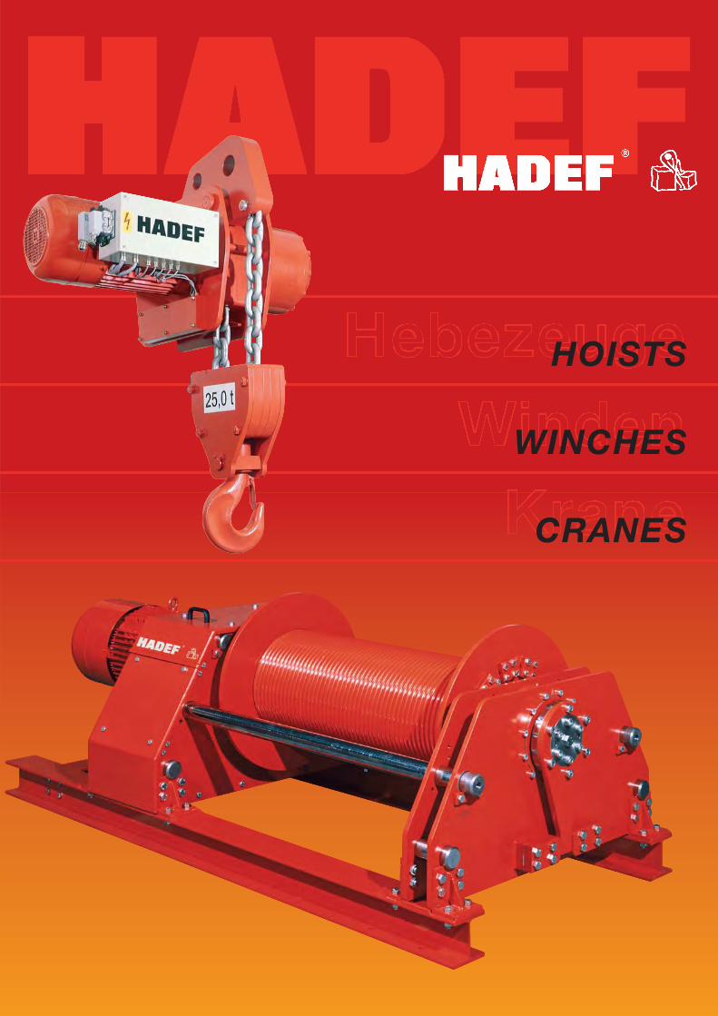
HOISTS
WINCHES
CRANES
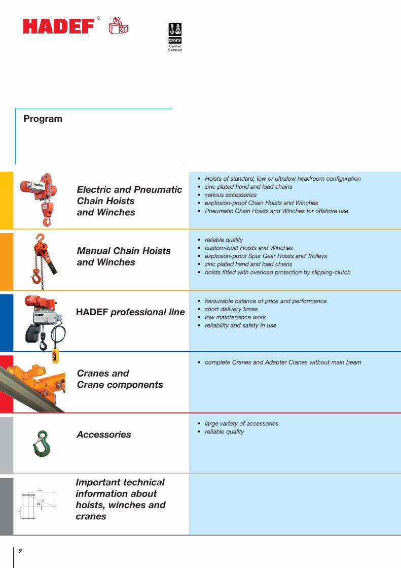
Program
2
Electric and PneumaticChain Hoists and Winches
HADEF professional line
Cranes and Crane components
Accessories
Important technicalinformation abouthoists, winches and cranes
Certified Company
• Hoists of standard, low or ultralow headroom configuration• zinc plated hand and load chains• various accessories• explosion-proof Chain Hoists and Winches• Pneumatic Chain Hoists and Winches for offshore use
• reliable quality• custom-built Hoists and Winches• explosion-proof Spur Gear Hoists and Trolleys• zinc plated hand and load chains• hoists fitted with overload protection by slipping-clutch
• favourable balance of price and performance• short delivery times• low maintenance work• reliability and safety in use
• complete Cranes and Adapter Cranes without main beam
• large variety of accessories • reliable quality
Manual Chain Hoistsand Winches
L 1
L 2 min.
Lastangriffs- bzw.Umlenkpunkt
3
Page
Content
This brochure shows an extract from our current product range.
For more information, please visit our website:
www.hadef.com
Photos of HADEF Hoists in use 4
Electric Chain Hoists 10Electric Chain Hoists / low and ultralow headroom configuration 14Pneumatic Chain Hoists / low and ultralow headroom configuration 18Electric Winches 20Pneumatic Winches 23Ex-version Hoists and Winches 24Hoists and Winches for offshore use 25
Spur Gear Hoists 26Monorail Trolleys 30Spur Gear Hoists / low and ultralow headroom configuration 31Ratchet Lever Hoists 32Manual Winches 34
Electric Chain Hoist 36Monorail Trolleys 38Beam Clamp 38Wirerope Pull Hoist 38Spur Gear Hoist 39Lever Hoists 39
Articulated Single Girder Underslung Crane 40Jib Cranes and wall-mounted Jib Cranes 41Single Girder Manual Underslung and Overhead Travelling Cranes 42Single Girder Electric Underslung and Overhead Travelling Cranes 43Adapter Cranes / End Carriages / Gantry Cranes 45
Wireropes / Wirerope Clamps / Eye Hooks / Heart Shaped Thimbles 46Wirerope Pulleys / Pedestals / Trolley Wheels / Hand Chain Wheels Trolley End StopsLow Voltage Control / Pendant Control
FEM (drive mechanism) groups 47Important mechanical engineering formula 48Simplified check of the chain / Simplified wirerope determination 49Power / Torque / Gear transmission / Braking moment 50Suspension, Lifting and Track Height/ Frequency converter/ Dimensioning of beam/ Positionning switch 51Phase monitoring relay/ Testing of cranes/ Low voltage control 52Wirerope exit/ Insulation classes 53ATEX / EX 54
4
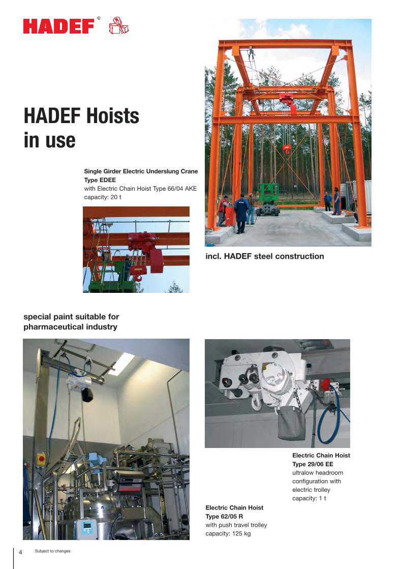
HADEF Hoists in use
Subject to changes
Electric Chain Hoist Type 29/06 EEultralow headroom configuration with electric trolley capacity: 1 t
Electric Chain Hoist Type 62/05 Rwith push travel trolleycapacity: 125 kg
Single Girder Electric Underslung CraneType EDEEwith Electric Chain Hoist Type 66/04 AKEcapacity: 20 t
special paint suitable for pharmaceutical industry
incl. HADEF steel construction
5Subject to changes
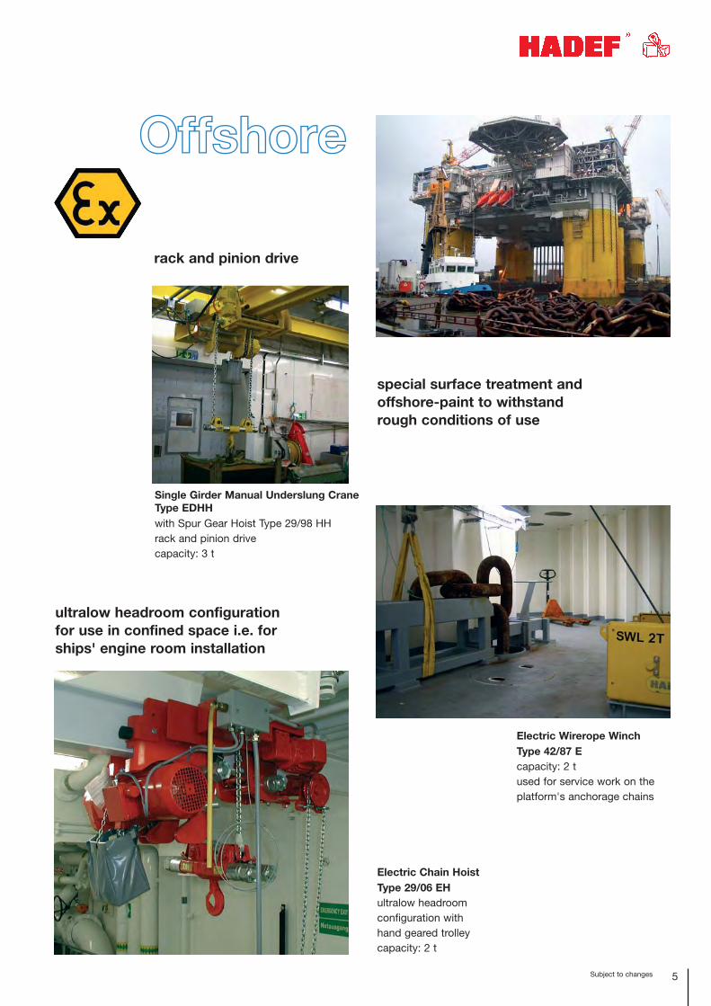
Electric Chain Hoist Type 29/06 EHultralow headroom configuration with hand geared trolleycapacity: 2 t
Electric Wirerope WinchType 42/87 Ecapacity: 2 tused for service work on theplatform's anchorage chains
Single Girder Manual Underslung CraneType EDHHwith Spur Gear Hoist Type 29/98 HHrack and pinion drivecapacity: 3 t
special surface treatment and offshore-paint to withstand rough conditions of use
ultralow headroom configuration for use in confined space i.e. for ships' engine room installation
rack and pinion drive
Offshore
6
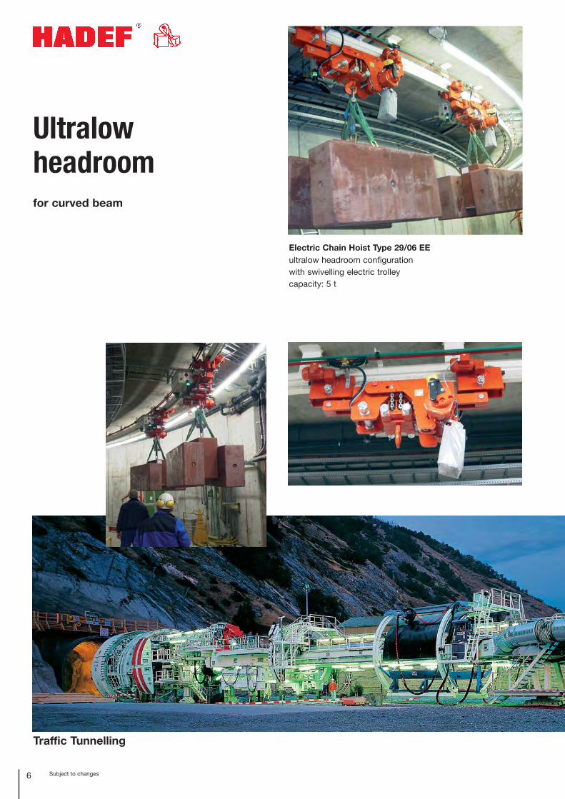
Ultralowheadroomfor curved beam
Subject to changes
Electric Chain Hoist Type 29/06 EEultralow headroom configurationwith swivelling electric trolleycapacity: 5 t
Traffic Tunnelling
7Subject to changes
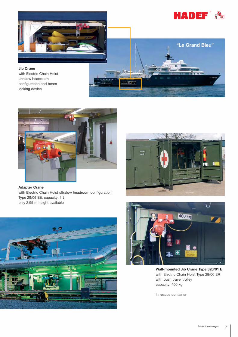
Wall-mounted Jib Crane Type 320/01 Ewith Electric Chain Hoist Type 28/06 ERwith push travel trolleycapacity: 400 kg
in rescue container
Jib Cranewith Electric Chain Hoistultralow headroomconfiguration and beam locking device
Adapter Cranewith Electric Chain Hoist ultralow headroom configurationType 29/06 EE, capacity: 1 tonly 2,95 m height available
“Le Grand Bleu”
8 Subject to changes
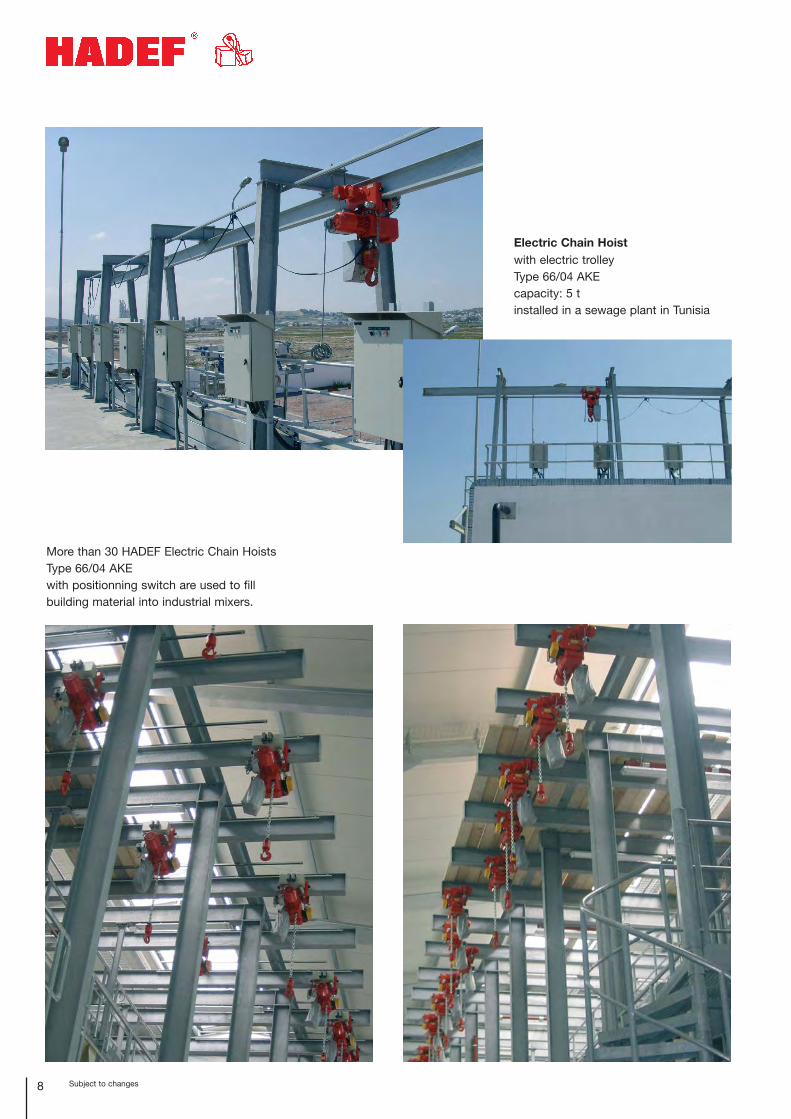
Electric Chain Hoistwith electric trolleyType 66/04 AKEcapacity: 5 tinstalled in a sewage plant in Tunisia
More than 30 HADEF Electric Chain HoistsType 66/04 AKEwith positionning switch are used to fill building material into industrial mixers.
9Subject to changes
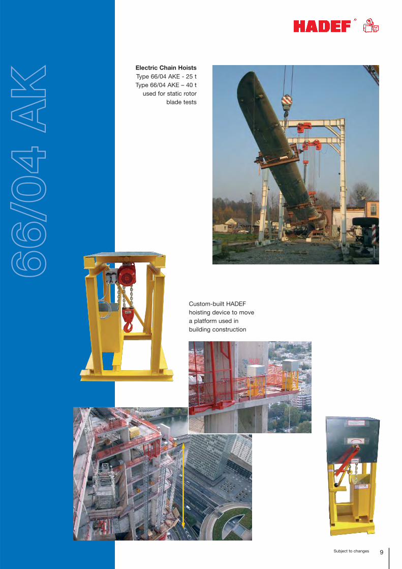
Custom-built HADEFhoisting device to movea platform used inbuilding construction
Electric Chain HoistsType 66/04 AKE - 25 tType 66/04 AKE – 40 t
used for static rotorblade tests
66/0
4 A
K
10 Subject to changes
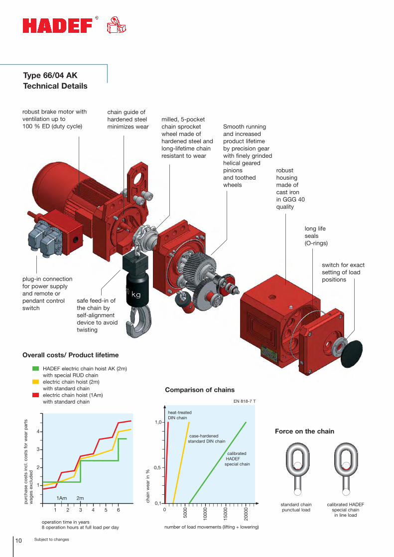
safe feed-in of the chain by self-alignment device to avoid twisting
milled, 5-pocket chain sprocket wheel made of hardened steel and long-lifetime chain resistant to wear
Smooth running and increased product lifetime by precision gear with finely grindedhelical geared pinions and toothed wheels
long life seals (O-rings)
switch for exactsetting of loadpositions
robust housingmade of cast ironin GGG 40 quality
plug-in connectionfor power supplyand remote orpendant controlswitch
Type 66/04 AKTechnical Details
robust brake motor withventilation up to 100 % ED (duty cycle)
chain guide ofhardened steelminimizes wear
���
���
����
����
�
����
�
����
�
���
�
Comparison of chains
Force on the chain
chai
n w
ear
in %
number of load movements (lifting + lowering)
standard chain punctual load
calibrated HADEFspecial chain in line load
heat-treated DIN chain
case-hardened standard DIN chain
calibratedHADEF
special chain
EN 818-7 T
�
�
�
�
� � � � �
�� ��
pur
chas
e co
sts
incl
. co
sts
for
wea
r p
arts
wag
es e
xclu
ded
operation time in years8 operation hours at full load per day
Overall costs/ Product lifetime
HADEF electric chain hoist AK (2m) with special RUD chainelectric chain hoist (2m) with standard chainelectric chain hoist (1Am) with standard chain
11Subject to changes
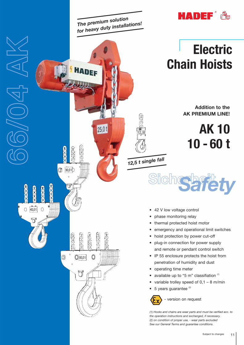
Electric Chain Hoists
• 42 V low voltage control
• phase monitoring relay
• thermal protected hoist motor
• emergency and operational limit switches
• hoist protection by power cut-off
• plug-in connection for power supply
and remote or pendant control switch
• IP 55 enclosure protects the hoist from
penetration of humidity and dust
• operating time meter
• available up to “5 m” classifiation (1)
• variable trolley speed of 0,1 – 8 m/min
• 5 years guarantee (2)
(1) Hooks and chains are wear parts and must be verified acc. tothe operation instructions and exchanged, if necessary.(2) on condition of proper use, - wear parts excludedSee our General Terms and guarantee conditions.
- version on request
The premium solution
for heavy duty installations!
12,5 t single fall
SicherheitSafety
66/0
4 A
K
AK 1010 - 60 t
Addition to the AK PREMIUM LINE!
Subject to changes12
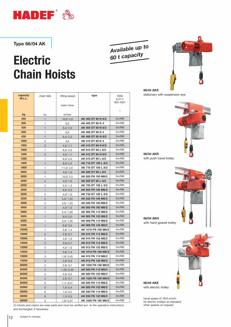
Type 66/04 AK
travel speed of 16/4 m/minfor electric trolleys as standard,other speeds on request.
66/04 AKSstationary with suspension eye
66/04 AKRwith push travel trolley
66/04 AKHwith hand geared trolley
66/04 AKEwith electric trolley
Available up to
60 t capacity
ElectricChain Hoists
capacity W.L.L.
kg
250
500
500
630
630
1000
1000
1000
1250
1250
1600
1600
2000
2000
2500
2500
2500
3200
3200
4000
5000
5000
5000
6300
6300
10000
10000
10000
12000
12000
12500
15000
15000
20000
20000
20000
25000
25000
25000
30000
30000
30000
chain falls
no.
1
1
1
1
1
2
2
1
2
1
1
1
2
1
2
2
1
2
2
2
2
1
1
1
1
1
2
2
2
2
1
3
3
2
4
4
2
5
5
6
6
3
type
AK 402 DT 80 N 8/2
AK 405 DT 80 K 4
AK 405 DT 80 N 8/2
AK 406 DT 80 K 4
AK 406 DT 80 N 8/2
AK 410 DT 80 K 4
AK 410 DT 80 N 8/2
AK 610 DT 90 L 8/2
AK 412 DT 80 N 8/2
AK 612 DT 90 L 8/2
AK 716 DT 100 L 8/2
AK 716 DT 100 L 8/2
AK 620 DT 90 L 8/2
AK 820 FN 100 M8/2
AK 625 DT 90 L 8/2
AK 725 DT 100 L 8/2
AK 825 FN 100 M8/2
AK 732 DT 100 L 8/2
AK 832 FN 100 M8/2
AK 840 FN 100 M8/2
AK 850 FN 100 M8/2
AK 905 FN 112 M8/2
AK 905 FN 132 M8/2
AK 906 FN 112 M8/2
AK 906 FN 132 M8/2
AK 1010 FN 160 M8/2
AK 910 FN 112 M8/2
AK 910 FN 132 M8/2
AK 912 FN 112 M8/2
AK 912 FN 132 M8/2
AK 1012 FN 160 M8/2
AK 915 FN 112 M8/2
AK 915 FN 132 M8/2
AK 1020 FN 160 M8/2
AK 920 FN 112 M8/2
AK 920 FN 132 M8/2
AK 1025 FN 160 M8/2
AK 925 FN 112 M8/2
AK 925 FN 132 M8/2
AK 930 FN 112 M8/2
AK 930 FN 132 M8/2
AK 1030 FN 160 M8/2
FEM9.511/
ISO 4301
(1)
3m/M6
3m/M6
3m/M6
3m/M6
3m/M6
3m/M6
3m/M6
3m/M6
3m/M6
3m/M6
3m/M6
3m/M6
3m/M6
3m/M6
3m/M6
3m/M6
3m/M6
3m/M6
3m/M6
3m/M6
3m/M6
3m/M6
3m/M6
3m/M6
3m/M6
3m/M6
3m/M6
3m/M6
3m/M6
3m/M6
3m/M6
3m/M6
3m/M6
3m/M6
3m/M6
3m/M6
3m/M6
3m/M6
3m/M6
3m/M6
3m/M6
3m/M6
lifting speed
main/ slow
m/min
16,0/ 4,0
6,0
9,4/ 2,3
6,0
9,4/ 2,3
3,0
4,5/ 1,1
8,0/ 2,0
4,5/ 1,1
8,0/ 2,0
8,0/ 2,0
11,0/ 2,6
4,0/ 1,0
10,0/ 2,5
4,0/ 1,0
5,5/ 1,3
8,0/ 2,0
4,0/ 1,0
5,0/ 1,25
5,0/ 1,25
4,0/ 1,0
5,4/ 1,35
8,0/ 2,0
5,4/ 1,35
8,0/ 2,0
5,8/ 1,4
2,8/ 0,7
4,0/ 1,0
2,8/ 0,7
4,0/ 1,0
5,8/ 1,4
1,8/ 0,45
2,6/ 0,6
2,9/ 0,7
1,35/ 0,35
2,0/ 0,5
2,9/ 0,7
1,1/ 0,27
1,6/ 0,4
1,0/ 0,2
1,3/ 0,3
1,9/ 0,47
(1) Hooks and chains are wear parts and must be verified acc. to the operation instructions and exchanged, if necessary.
Subject to changes 13
Electric Chain Hoists
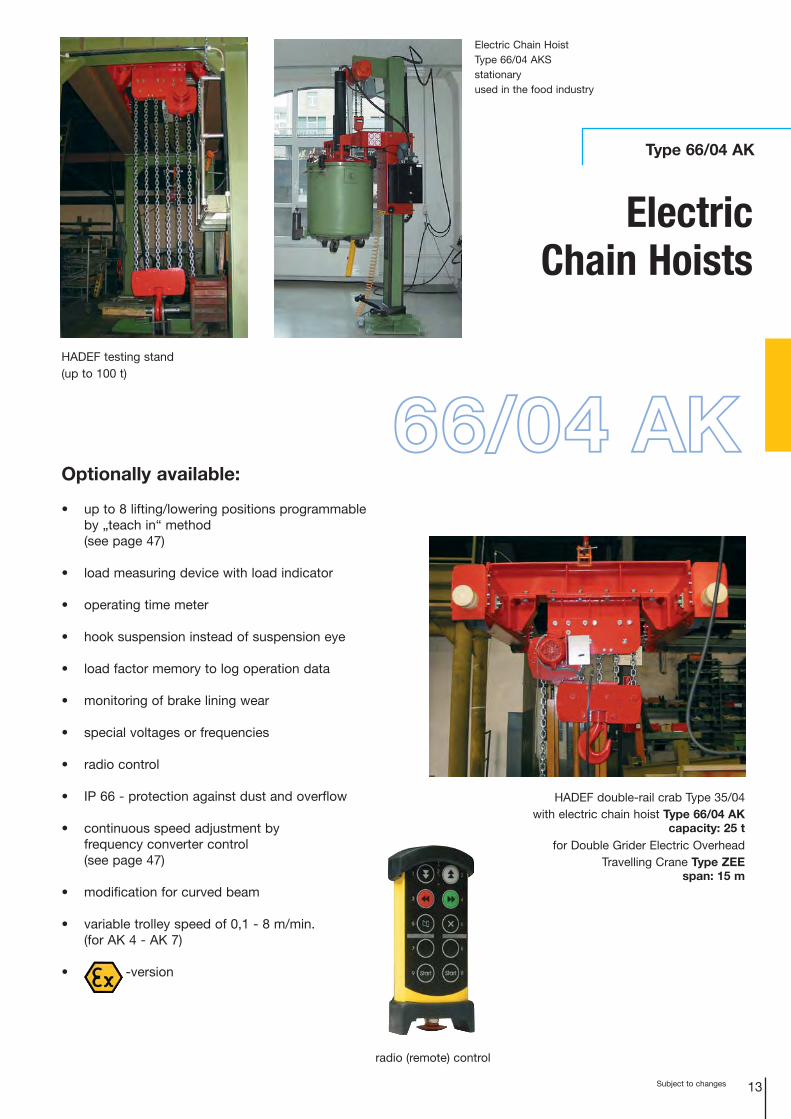
Type 66/04 AK
Optionally available:
• up to 8 lifting/lowering positions programmableby „teach in“ method (see page 47)
• load measuring device with load indicator
• operating time meter
• hook suspension instead of suspension eye
• load factor memory to log operation data
• monitoring of brake lining wear
• special voltages or frequencies
• radio control
• IP 66 - protection against dust and overflow
• continuous speed adjustment by frequency converter control (see page 47)
• modification for curved beam
• variable trolley speed of 0,1 - 8 m/min.(for AK 4 - AK 7)
• -version
HADEF double-rail crab Type 35/04with electric chain hoist Type 66/04 AK
capacity: 25 tfor Double Grider Electric Overhead
Travelling Crane Type ZEE span: 15 m
HADEF testing stand(up to 100 t)
radio (remote) control
66/04 AK
Electric Chain HoistType 66/04 AKS stationaryused in the food industry
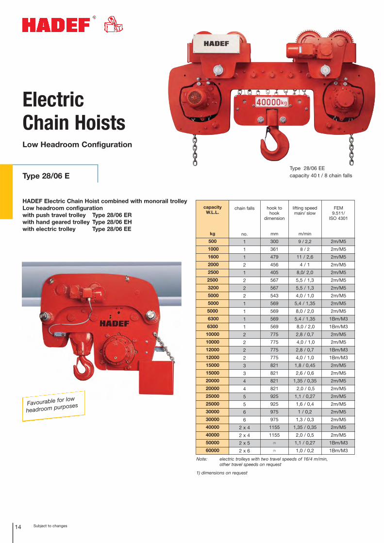
Favourable for low
headroom purposes
HADEF Electric Chain Hoist combined with monorail trolleyLow headroom configurationwith push travel trolley Type 28/06 ERwith hand geared trolley Type 28/06 EHwith electric trolley Type 28/06 EE
ElectricChain HoistsLow Headroom Configuration
Type 28/06 EType 28/06 EEcapacity 40 t / 8 chain falls
capacity W.L.L.
kg
500
1000
1600
2000
2500
2500
3200
5000
5000
5000
6300
6300
10000
10000
12000
12000
15000
15000
20000
20000
25000
25000
30000
30000
40000
40000
50000
60000
chain falls
no.
1
1
1
2
1
2
2
2
1
1
1
1
2
2
2
2
3
3
4
4
5
5
6
6
2 x 4
2 x 4
2 x 5
2 x 6
lifting speedmain/ slow
m/min
9 / 2,2
8 / 2
11 / 2,6
4 / 1
8,0/ 2,0
5,5 / 1,3
5,5 / 1,3
4,0 / 1,0
5,4 / 1,35
8,0 / 2,0
5,4 / 1,35
8,0 / 2,0
2,8 / 0,7
4,0 / 1,0
2,8 / 0,7
4,0 / 1,0
1,8 / 0,45
2,6 / 0,6
1,35 / 0,35
2,0 / 0,5
1,1 / 0,27
1,6 / 0,4
1 / 0,2
1,3 / 0,3
1,35 / 0,35
2,0 / 0,5
1,1 / 0,27
1,0 / 0,2
FEM9.511/
ISO 4301
2m/M5
2m/M5
2m/M5
2m/M5
2m/M5
2m/M5
2m/M5
2m/M5
2m/M5
2m/M5
1Bm/M3
1Bm/M3
2m/M5
2m/M5
1Bm/M3
1Bm/M3
2m/M5
2m/M5
2m/M5
2m/M5
2m/M5
2m/M5
2m/M5
2m/M5
2m/M5
2m/M5
1Bm/M3
1Bm/M3
hook to hook
dimension
mm
300
361
479
456
405
567
567
543
569
569
569
569
775
775
775
775
821
821
821
821
925
925
975
975
1155
1155(1)
(1)
Note: electric trolleys with two travel speeds of 16/4 m/min, other travel speeds on request
1) dimensions on request
14 Subject to changes
15Subject to changes
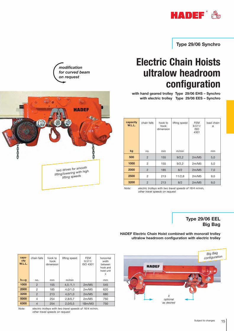
Type 29/06 Synchro
with hand geared trolley Type 29/06 EHS – Synchro with electric trolley Type 29/06 EES – Synchro
capacity W.L.L.
kg
500
1000
2000
2500
3200
chain falls
no.
2
2
2
2
2
lifting speed
m/min
9/2,2
9/2,2
8/2
11/2,6
8/2
FEM9.511/
ISO4301
2m/M5
2m/M5
2m/M5
2m/M5
2m/M5
load chainø
mm
5,0
5,0
7,0
9,0
9,0
hook tohook
dimension
mm
155
155
185
213
213
two drives for smooth
lifting/lowering with high
lifting speeds
Note: electric trolleys with two travel speeds of 16/4 m/min, other travel speeds on request
capa-city
W.L.L.
k≥≥g
1000
2000
3200
5000
6300
chain falls
no.
2
2
2
4
4
lifting speed
m/min
4,5 /1,1
4,0/1,0
4,0/1,0
2,8/0,7
2,0/0,5
FEM9.511/
ISO 4301
2m/M5
2m/M5
2m/M5
2m/M5
1Bm/M3
hook tohook
dimension
mm
155
185
213
254
254
horizontal width
between hook and hoist unit
x
mm
545
620
680
750
750
Note: electric trolleys with two travel speeds of 16/4 m/min, other travel speeds on request
X optional
as desired
Big Bag
configuration
Type 29/06 EEL Big Bag
HADEF Electric Chain Hoist combined with monorail trolleyultralow headroom configuration with electric trolley
modification for curved beamon request
Electric Chain Hoistsultralow headroom
configuration
Subject to changes16
capacity W.L.L.
kg
1000
2000
2500
3200
5000
5000
6300
10000
10000
12000
16000
20000
25000
30000
40000
50000
60000
chain falls
no.
2
2
2
2
4
2
4
4
2
2
4
4
6
6
2x4
2x5
2x6
lifting speed
main/ slow
m/min
4,5/ 1,1
4,0/ 1,0
5,5/ 1,3
5,5/ 1,3
2,8/ 0,7
4,0/ 1,0
2,0/ 0,5
2,0/ 0,5
2,8/ 0,7
2,8/ 0,7
1,4/ 0,3
1,4/ 0,3
1,0/ 0,2
1,0/ 0,2
1,4/ 0,3
1,1/ 0,27
1,0/ 0,2
FEM9.511/
ISO 4301
2m/M5
2m/M5
2m/M5
2m/M5
2m/M5
2m/M5
1Bm/M3
2m/M5
2m/M5
1Bm/M3
3m/M6
2m/M5
2m/M5
2m/M5
2m/M5
2m/M5
1Bm/M3
hook to hookdimension
mm
155
185
213
213
276
280
276
305
360
360
407
487
575
575
710
730(1)
Note: electric trolleys as standard with 16/4 m/min, other travel speeds on request
1) dimensions on request.
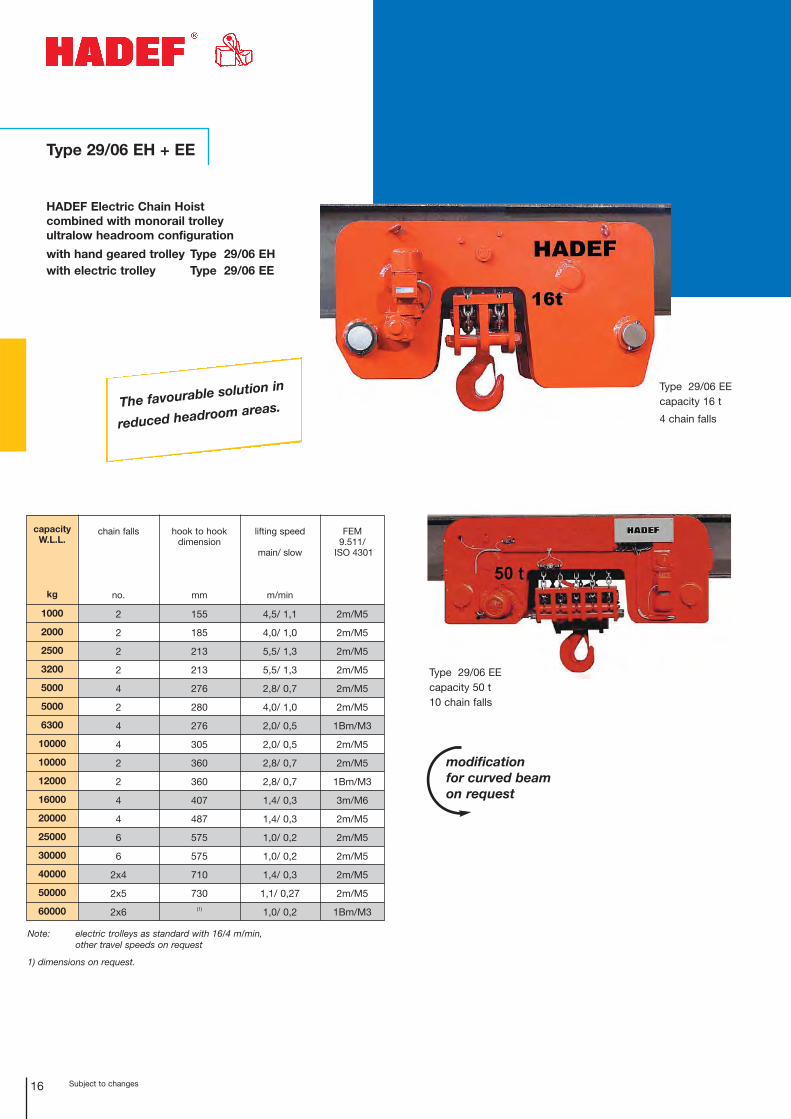
modification for curved beamon request
The favourable solution in
reduced headroom areas.
Type 29/06 EEcapacity 50 t10 chain falls
Type 29/06 EEcapacity 16 t
4 chain falls
Type 29/06 EH + EE
HADEF Electric Chain Hoist combined with monorail trolley ultralow headroom configuration
with hand geared trolley Type 29/06 EHwith electric trolley Type 29/06 EE
17Subject to changes
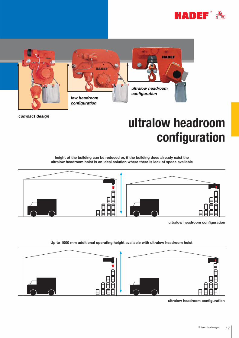
ultralow headroomconfiguration
low headroom configuration
compact design
height of the building can be reduced or, if the building does already exist the ultralow headroom hoist is an ideal solution where there is lack of space available
Up to 1000 mm additional operating height available with ultralow headroom hoist
ultralow headroom configuration
ultralow headroom configuration
ultralow headroom configuration
Subject to changes
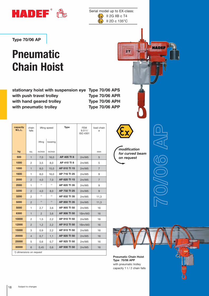
Type 70/06 AP
18
Pneumatic Chain Hoist
stationary hoist with suspension eye Type 70/06 APSwith push travel trolley Type 70/06 APRwith hand geared trolley Type 70/06 APHwith pneumatic trolley Type 70/06 APP
Pneumatic Chain HoistType 70/06 APPwith pneumatic trolleycapacity 1 t / 2 chain falls
lowering
m/min
16,0
8,0
15,0
16,0
7,0
(1)
8,0
(1)
(1)
3,6
3,6
2,2
2,2
2,2
1,1
0,7
0,6
lifting
m/min
7,0
3,5
8,0
8,0
4,0
(1)
4,0
(1)
(1)
2,7
2
1,5
1,2
0,9
0,7
0,6
0,45
capacity W.L.L.
kg
500
1000
1000
1600
2000
2000
3200
3200
5000
5000
6300
10000
12000
15000
20000
25000
30000
chainfalls
no.
1
2
1
1
2
1
2
2
2
1
1
2
2
3
4
5
6
load chainø
mm
5
5
7
9
7
9
9
11,3
11,3
16
16
16
16
16
16
16
16
Type
AP 405 TI 8
AP 410 TI 8
AP 610 TI 15
AP 716 TI 25
AP 620 TI 15
AP 820 TI 35
AP 732 TI 25
AP 832 TI 35
AP 850 TI 35
AP 905 TI 50
AP 906 TI 50
AP 910 TI 50
AP 912 TI 50
AP 915 TI 50
AP 920 TI 50
AP 925 TI 50
AP 930 TI 50
FEM9.511/
ISO 4301
2m/M5
2m/M5
2m/M5
2m/M5
2m/M5
2m/M5
2m/M5
2m/M5
2m/M5
2m/M5
1Bm/M3
2m/M5
1Bm/M3
2m/M5
2m/M5
2m/M5
2m/M5
1) dimensions on request
lifting speed
Serial model up to EX-class:II 2G IIB c T4II 2D c 135°C
70/0
6 A
Pmodification for curved beamon request
Subject to changes 19
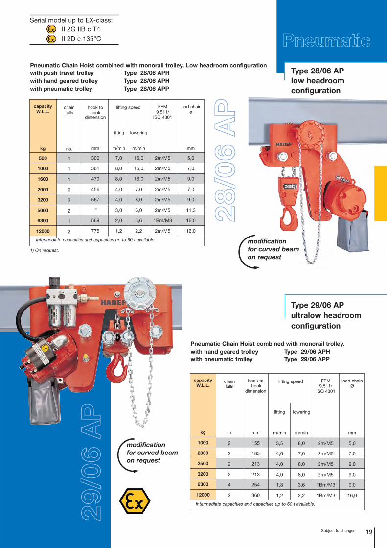
Type 28/06 APlow headroom configuration
Type 29/06 APultralow headroomconfiguration
Pneumatic Chain Hoist combined with monorail trolley. Low headroom configurationwith push travel trolley Type 28/06 APR with hand geared trolley Type 28/06 APH with pneumatic trolley Type 28/06 APP
Pneumatic Chain Hoist combined with monorail trolley. with hand geared trolley Type 29/06 APH with pneumatic trolley Type 29/06 APP
29/0
6 A
P
PneumaticSerial model up to EX-class:
II 2G IIB c T4II 2D c 135°C
modification for curved beamon request
modification for curved beamon request
28/0
6 A
P
lowering
m/min
16,0
15,0
16,0
7,0
8,0
6,0
3,6
2,2
lifting
m/min
7,0
8,0
8,0
4,0
4,0
3,0
2,0
1,2
load chain ø
mm
5,0
7,0
9,0
7,0
9,0
11,3
16,0
16,0
capacityW.L.L.
kg
500
1000
1600
2000
3200
5000
6300
12000
chain falls
no.
1
1
1
2
2
2
1
2
lifting speed FEM9.511/
ISO 4301
2m/M5
2m/M5
2m/M5
2m/M5
2m/M5
2m/M5
1Bm/M3
2m/M5
hook tohook
dimension
mm
300
361
479
456
567
(1)
569
775
1) On request.
chain falls
no.
2
2
2
2
4
2
lowering
m/min
8,0
7,0
8,0
8,0
3,6
2,2
lifting
m/min
3,5
4,0
4,0
4,0
1,8
1,2
load chainØ
mm
5,0
7,0
9,0
9,0
9,0
16,0
capacity W.L.L.
kg
1000
2000
2500
3200
6300
12000
lifting speed FEM9.511/
ISO 4301
2m/M5
2m/M5
2m/M5
2m/M5
1Bm/M3
1Bm/M3
hook tohook
dimension
mm
155
185
213
213
254
360
Intermediate capacities and capacities up to 60 t available.
Intermediate capacities and capacities up to 60 t available.
Subject to changes20
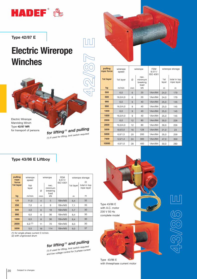
Type 43/86 E Liftboy
Type 42/87 E
Electric WireropeWinches
Electric Wirerope Manriding WinchType 42/87 MRfor transport of persons
Type 43/86 Ewith A.C. motor 230 V 50 Hzcomplete model
Type 43/86 Ewith threephase current motor
1st layer
m
24,0
24,0
25,0
25,0
25,0
25,0
30,0
30,0
31,0
35,0
47,0
50,0
pullingrope force
1st layer
kg
500
500
990
990
1000
1000
2000
2000
3200
5000
7500
10000
wirerope speed
1st layer
m/min
6,0
16,0/4,0
6,0
16,0/4,0
6,0
16,0/4,0
6,0
16,0/4,0
8,0/2,0
6,0/1,5
5,5/1,4
4,0/1,0
Ø
mm
6
6
9
9
9
9
12
12
16
20
24
28
nec.minimumbreaking
loadkN
20
20
40
40
40
40
80
80
128
200
300
400
total in toprope layer
m
179
179
145
145
145
145
226
226
23
259
350
280
wirerope storage
1st layer
m
6,4
7,1
5,7
8,4
8,4
8,0
9,0
pullingropeforce
1st layer
kg
125
250
500
990
1000
2000
3200
wirerope speed
toplayer
m/min
11,0
7,0
4,0
6,0
6,0
6,0 (1)
5,5
Ø
mm
4
4
6
8
8
11
16
nec. minimumbreaking
loadkN
5
9
18
36
36
70
114
FEM9.511/
ISO 4301
1Bm/M3
1Bm/M3
1Bm/M3
1Bm/M3
1Bm/M3
1Bm/M3
1Bm/M3
(2)
total in toprope layer
m
32
35
30
30
30
30
37
wirerope storage wirerope
(1) for single phase current 3 m/min.(2) with ungrooved drum
42/8
7 E
wirerope FEM9.511/
ISO 4301
1Am/M4
1Am/M4
1Am/M4
1Am/M4
1Am/M4
1Am/M4
1Am/M4
1Am/M4
1Am/M4
1Am/M4
1Am/M4
1Am/M4
43/8
6 E
for lifting (1) and pulling
(1) If used for lifting, limit switch required
for lifting (1) and pulling
(1) If used for lifting, limit switch required
and low voltage control for 3-phase current
21Subject to changes
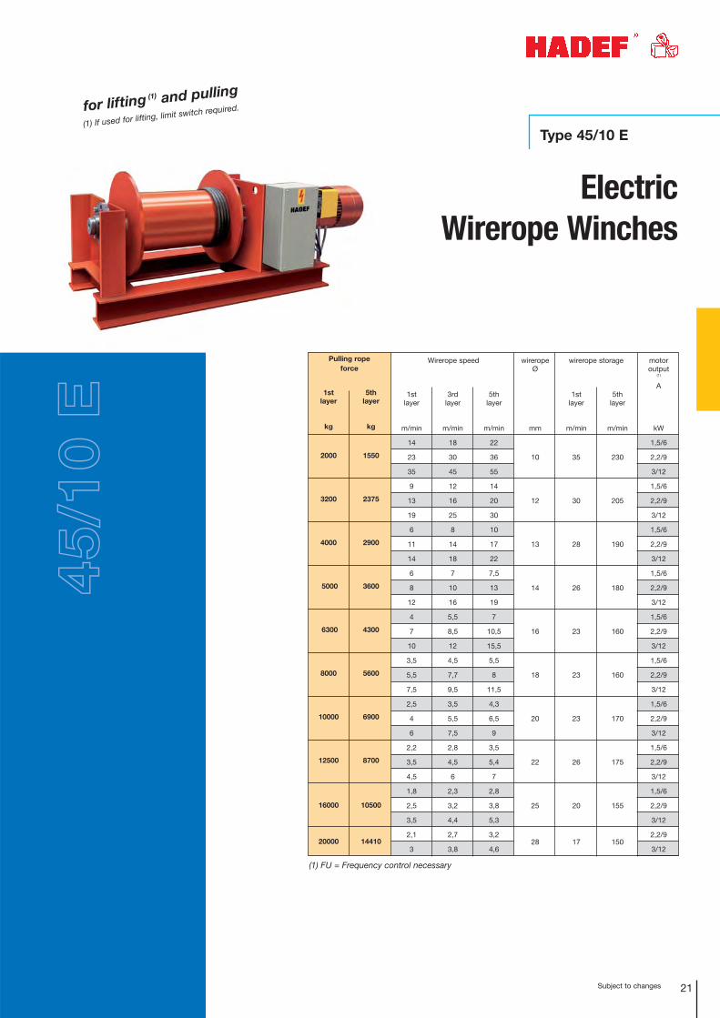
Type 45/10 E
Electric Wirerope Winches
for lifting (1) and pulling
(1) If used for lifting, limit switch required.45
/10
E
Pulling rope force
1stlayer
kg
2000
3200
4000
5000
6300
8000
10000
12500
16000
20000
5thlayer
kg
1550
2375
2900
3600
4300
5600
6900
8700
10500
14410
Wirerope speed wirerope storage
1stlayer
m/min
14
23
35
9
13
19
6
11
14
6
8
12
4
7
10
3,5
5,5
7,5
2,5
4
6
2,2
3,5
4,5
1,8
2,5
3,5
2,1
3
3rdlayer
m/min
18
30
45
12
16
25
8
14
18
7
10
16
5,5
8,5
12
4,5
7,7
9,5
3,5
5,5
7,5
2,8
4,5
6
2,3
3,2
4,4
2,7
3,8
5thlayer
m/min
22
36
55
14
20
30
10
17
22
7,5
13
19
7
10,5
15,5
5,5
8
11,5
4,3
6,5
9
3,5
5,4
7
2,8
3,8
5,3
3,2
4,6
wirerope Ø
mm
10
12
13
14
16
18
20
22
25
28
1stlayer
m/min
35
30
28
26
23
23
23
26
20
17
5thlayer
m/min
230
205
190
180
160
160
170
175
155
150
motoroutput
(1)
A
kW
1,5/6
2,2/9
3/12
1,5/6
2,2/9
3/12
1,5/6
2,2/9
3/12
1,5/6
2,2/9
3/12
1,5/6
2,2/9
3/12
1,5/6
2,2/9
3/12
1,5/6
2,2/9
3/12
1,5/6
2,2/9
3/12
1,5/6
2,2/9
3/12
2,2/9
3/12
(1) FU = Frequency control necessary
22 Subject to changes
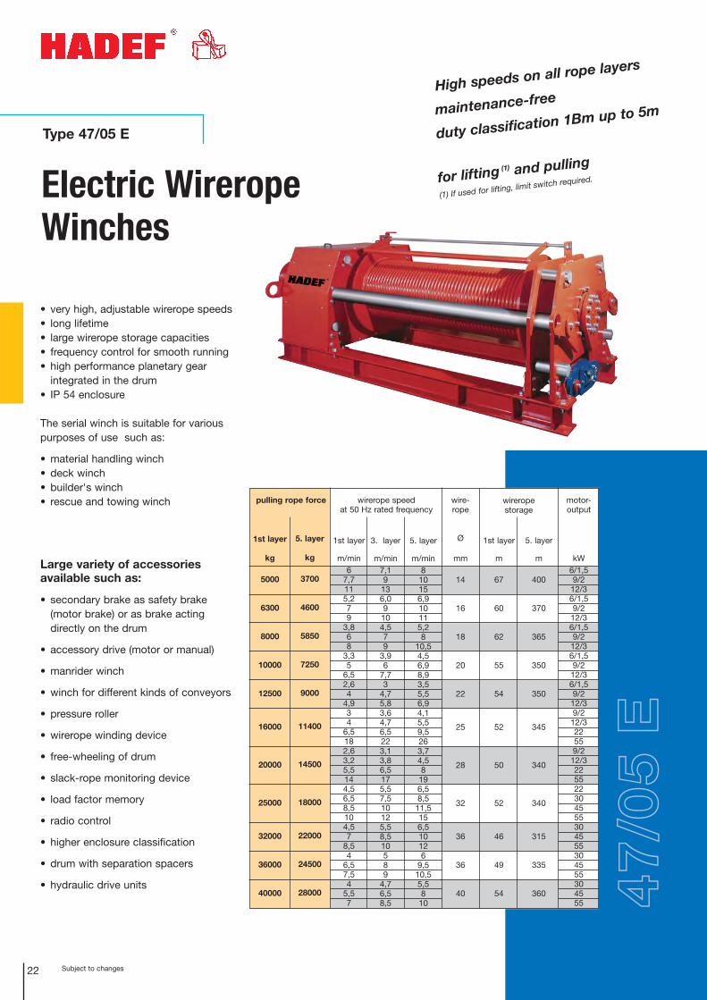
Electric WireropeWinches
Type 47/05 E
• very high, adjustable wirerope speeds• long lifetime• large wirerope storage capacities• frequency control for smooth running• high performance planetary gear
integrated in the drum• IP 54 enclosure
The serial winch is suitable for various purposes of use such as:
• material handling winch• deck winch• builder's winch• rescue and towing winch
Large variety of accessories available such as:
• secondary brake as safety brake (motor brake) or as brake acting directly on the drum
• accessory drive (motor or manual)
• manrider winch
• winch for different kinds of conveyors
• pressure roller
• wirerope winding device
• free-wheeling of drum
• slack-rope monitoring device
• load factor memory
• radio control
• higher enclosure classification
• drum with separation spacers
• hydraulic drive units
High speeds on all rope layers
maintenance-free
duty classification 1Bm up to 5m
47/0
5 E
1st layer
m
67
60
62
55
54
52
50
52
46
49
54
1st layer
kg
5000
6300
8000
10000
12500
16000
20000
25000
32000
36000
40000
5. layer
kg
3700
4600
5850
7250
9000
11400
14500
18000
22000
24500
28000
1st layer
m/min6
7,7115,279
3,868
3,35
6,52,64
4,934
6,5182,63,25,5144,56,58,5104,57
8,54
6,57,54
5,57
3. layer
m/min7,19
136,09
104,579
3,96
7,73
4,75,83,64,76,5223,13,86,5175,57,510125,58,510589
4,76,58,5
5. layer
m/min8
10156,910115,28
10,54,56,98,93,55,56,94,15,59,5263,74,58
196,58,5
11,5156,510126
9,510,55,58
10
wire-rope
Ø
mm
14
16
18
20
22
25
28
32
36
36
40
motor-output
kW6/1,59/2
12/36/1,59/2
12/36/1,59/2
12/36/1,59/2
12/36/1,59/2
12/39/2
12/322559/2
12/3225522304555304555304555304555
5. layer
m
400
370
365
350
350
345
340
340
315
335
360
wirerope storage
pulling rope force wirerope speed at 50 Hz rated frequency
for lifting (1) and pulling
(1) If used for lifting, limit switch required.
Subject to changes
43/86 P
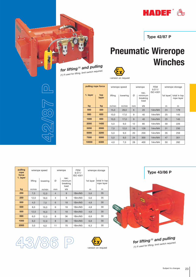
Type 42/87 P
Type 43/86 P
lowering
m/min
28,0
17,0
17,0
9,0
12,0
9,0
9,0
7,0
wirerope speed
1st layer
m
24
25
25
30
31
35
47
50
toplayer
kg
320
650
650
1400
2000
3200
5000
6300
1. layer
kg
500
990
1000
2000
3200
5000
7500
10000
lifting
m/min
15,0
10,0
10,0
5,0
7,0
5,0
5,0
4,0
total in toprope layer
m
179
145
145
226
230
259
351
282
wirerope storage pulling rope force
42/8
7 P
23
Ø
mm
6
9
9
12
16
20
24
28
nec.minimumbreaking
load
kN
20
40
40
80
128
200
300
400
wirerope FEM9.511/
ISO 4301
1Am/M4
1Am/M4
1Am/M4
1Am/M4
1Am/M4
1Am/M4
1Am/M4
1Am/M4
lowering
m/min
12,0
18,0
7,0
16,0
16,0
12,0
12,0
6,0
wirerope speed
1st layer
m
5,6
5,6
4,8
4,8
4,8
6,8
6,8
6,3
pulling rope force
1. layer
kg
250
250
500
500
500
990
1000
2000
lifting
m/min
7,0
12,0
4,0
8,0
12,0
6,0
6,0
3,0
Ø
mm
4
4
6
6
6
8
8
11
total in toprope layer
m
35
35
30
30
30
30
30
30
wirerope storage FEM9.511/
ISO 4301
1Bm/M3
1Bm/M3
1Bm/M3
1Bm/M3
1Bm/M3
1Bm/M3
1Bm/M3
1Bm/M3
nec.minimumbreaking
loadkN
9
9
18
18
18
36
36
70
wirerope
Pneumatic WireropeWinches
-version on request
-version on request
for lifting (1) and pulling
(1) If used for lifting, limit switch required.
for lifting (1) and pulling
(1) If used for lifting, limit switch required.
Subject to changes24
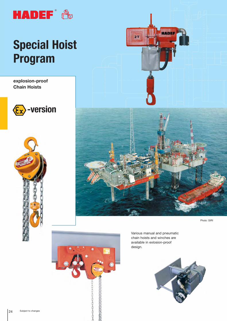
-version
Various manual and pneumaticchain hoists and winches areavailable in exlosion-proofdesign.
Photo: SIRI
Special HoistProgram
explosion-proof Chain Hoists
Subject to changes
Spezialgeräte
25
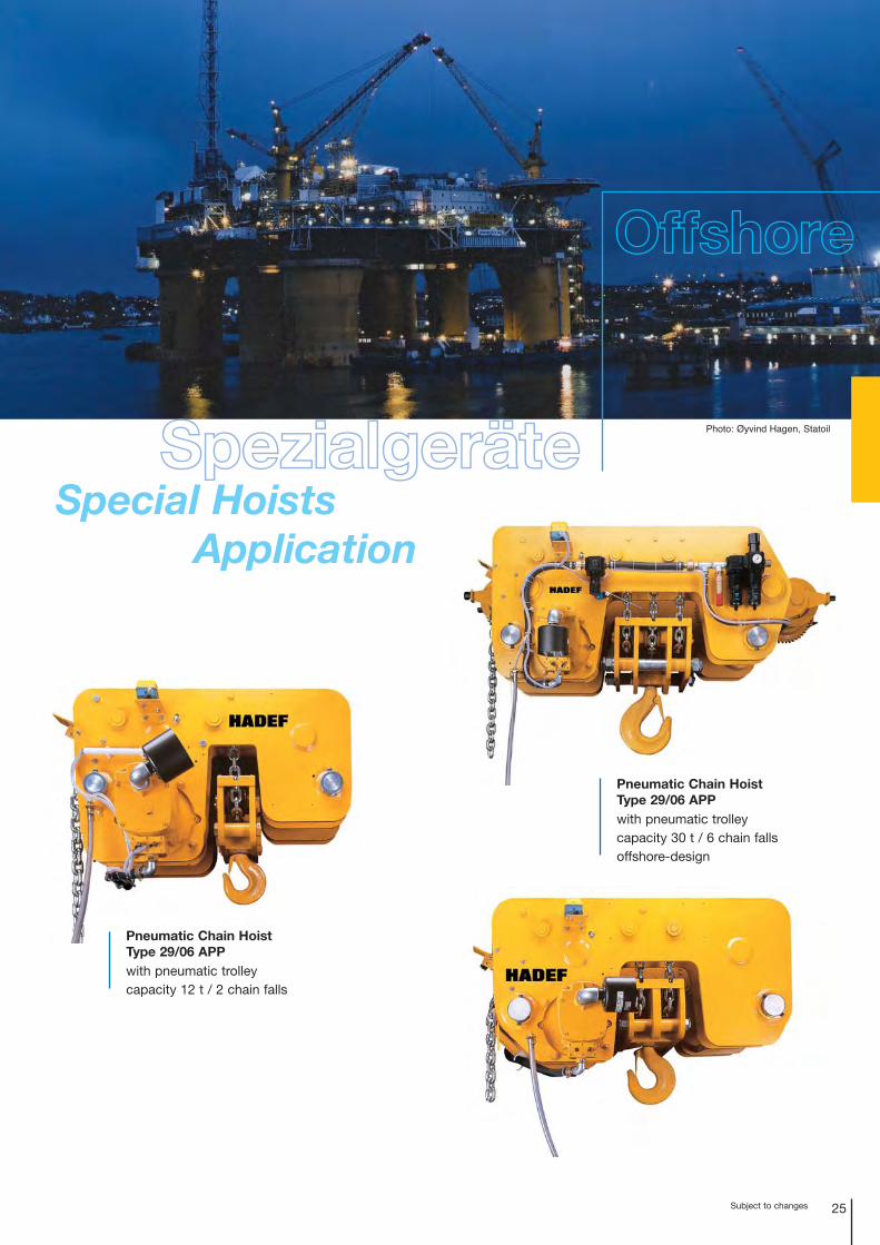
Pneumatic Chain HoistType 29/06 APPwith pneumatic trolleycapacity 12 t / 2 chain falls
Photo: Øyvind Hagen, Statoil
Special HoistsApplication
Offshore
Pneumatic Chain HoistType 29/06 APPwith pneumatic trolleycapacity 30 t / 6 chain fallsoffshore-design
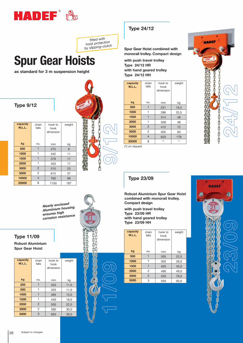
Subject to changes26
Type 9/12
Spur Gear Hoistsas standard for 3 m suspension height
chain falls
no.
1
1
1
1
2
2
4
8
weight
kg
8
11
17
17
23
37
99
187
hook tohook
dimension
mm
275
342
378
403
510
615
760
1150
capacity W.L.L.
kg
250
500
1000
1500
2000
3000
5000
chain falls
no.
1
1
1
1
2
2
3
weight
kg
11,0
11,0
13,0
18,0
22,0
30,0
39,0
hook tohook
dimension
mm
325
325
365
440
505
580
655
capacity W.L.L.
kg
500
1000
1500
2000
3000
5000
10000
20000
chain falls
no.
1
1
1
1
2
2
4
8
weight
kg
19,2
25,5
48
48
72
93
178(1)
hook tohook
dimension
mm
231
286
314
358
412
505
620(1)
Type 23/09
capacity W.L.L.
kg
500
1000
1500
2000
30005000
chain falls
no.
1
1
1
2
2
3
weight
kg
22,5
28,0
45,0
49,0
76,0
93,0
hook tohook
dimension
mm
305
355
455
490
535
550
Type 24/12
24/1
223
/09
9/12
fitted with
hoist protection
by slipping-clutch
capacity W.L.L.
kg
500
1000
1500
2000
3000
5000
10000
20000
Spur Gear Hoist combined with monorail trolley. Compact design
with push travel trolley Type 24/12 HR with hand geared trolley Type 24/12 HH
Type 11/09Robust AluminiumSpur Gear Hoist
Robust Aluminium Spur Gear Hoist combined with monorail trolley.Compact design
with push travel trolleyType 23/09 HR with hand geared trolleyType 23/09 HH
(1) on request
11/0
9
Nearly enclosed
Aluminium housing
ensures high
corosion resistance
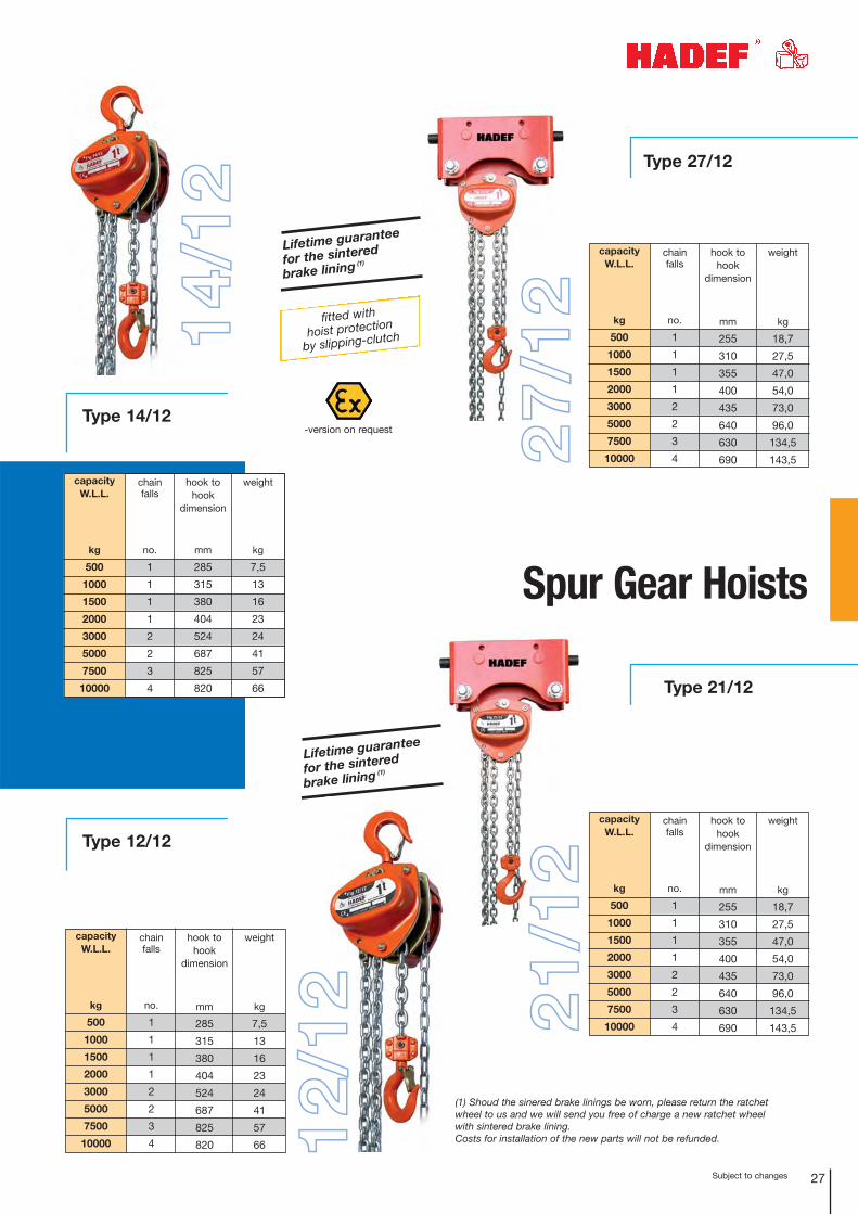
Type 14/12
Subject to changes 27
Lifetime guarantee
for the sintered
brake lining (1)
14/1
2 Type 27/12
Spur Gear Hoists
capacity W.L.L.
kg
500
1000
1500
2000
3000
5000
7500
10000
chain falls
no.
1
1
1
1
2
2
3
4
weight
kg
18,7
27,5
47,0
54,0
73,0
96,0
134,5
143,5
hook tohook
dimension
mm
255
310
355
400
435
640
630
690
-version on request
Type 21/12
capacity W.L.L.
kg
500
1000
1500
2000
3000
5000
7500
10000
chain falls
no.
1
1
1
1
2
2
3
4
weight
kg
18,7
27,5
47,0
54,0
73,0
96,0
134,5
143,5
hook tohook
dimension
mm
255
310
355
400
435
640
630
690
capacity W.L.L.
kg
500
1000
1500
2000
3000
5000
7500
10000
chain falls
no.
1
1
1
1
2
2
3
4
weight
kg
7,5
13
16
23
24
41
57
66
hook tohook
dimension
mm
285
315
380
404
524
687
825
820
fitted with
hoist protection
by slipping-clutch
capacity W.L.L.
kg
500
1000
1500
2000
3000
5000
7500
10000
chain falls
no.
1
1
1
1
2
2
3
4
weight
kg
7,5
13
16
23
24
41
57
66
hook tohook
dimension
mm
285
315
380
404
524
687
825
820
Lifetime guarantee
for the sintered
brake lining (1)
27/1
221
/12Type 12/12
(1) Shoud the sinered brake linings be worn, please return the ratchetwheel to us and we will send you free of charge a new ratchet wheelwith sintered brake lining. Costs for installation of the new parts will not be refunded.12
/12
28 Subjet to changes
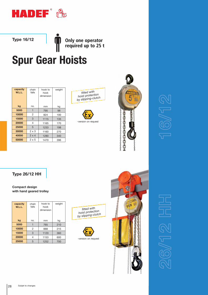
Spur Gear Hoists
Type 16/12
Type 26/12 HH
Compact designwith hand geared trolley
capacity W.L.L.
kg
5000
10000
15000
20000
25000
chain falls
no.
1
2
3
4
5
weight
kg
210
215
360
600
700
hook tohook
dimension
mm
765
888
1120
1153
1252
capacity W.L.L.
kg
5000
10000
15000
20000
25000
30000
40000
50000
chain falls
no.
1
2
3
4
5
2 x 3
2 x 4
2 x 5
weight
kg
98
100
135
170
198
270
340
396
hook tohook
dimension
mm
795
824
1115
1165
1233
1160
1280
1470
Only one operator required up to 25 t
16/1
226
/12
HH
-version on request
fitted with
hoist protection
by slipping-clutch
-version on request
fitted with
hoist protection
by slipping-clutch
29Subjet to changes
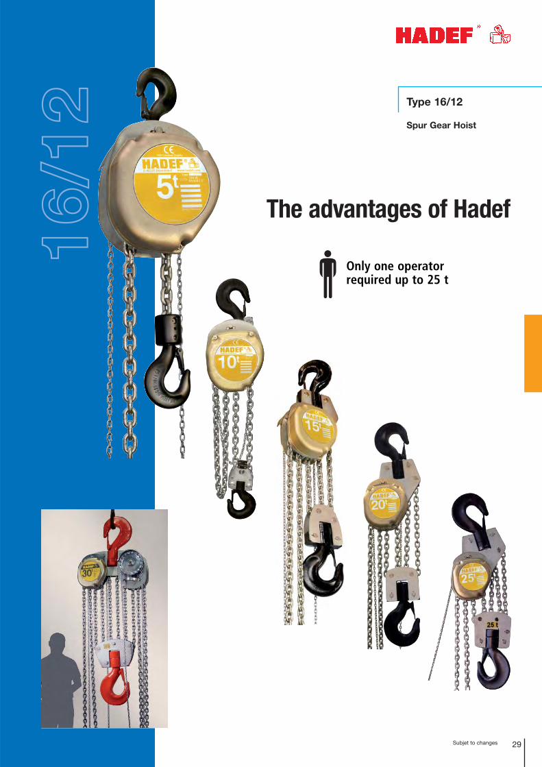
Type 16/12
Spur Gear Hoist
The advantages of Hadef
Only one operator required up to 25 t
16/1
2
Subject to changes30
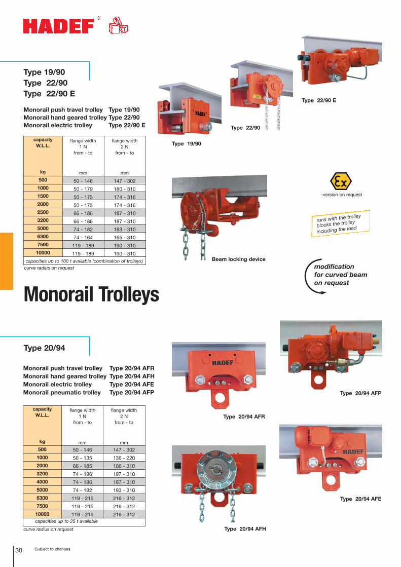
Monorail Trolleys
Type 20/94 AFR
Type 20/94 AFH
Type 20/94 AFE
capacityW.L.L.
kg
500
1000
2000
3200
4000
5000
6300
7500
10000
flange width 1 N
from - to
mm
50 - 146
50 - 135
66 - 185
74 - 196
74 - 196
74 - 192
119 - 215
119 - 215
119 - 215
flange width 2 N
from - to
mm
147 - 302
136 - 220
186 - 310
197 - 310
197 - 310
193 - 310
216 - 312
216 - 312
216 - 312capacities up to 25 t available
curve radius on request
modification for curved beamon request
Beam locking device
runs with the trolley
blocks the trolley
including the load
-version on request
Type 22/90
Type 22/90 E
Type 19/90
Type 19/90 Type 22/90Type 22/90 E
Type 20/94
Monorail push travel trolley Type 20/94 AFRMonorail hand geared trolley Type 20/94 AFHMonorail electric trolley Type 20/94 AFEMonorail pneumatic trolley Type 20/94 AFP
Monorail push travel trolley Type 19/90Monorail hand geared trolley Type 22/90Monorail electric trolley Type 22/90 E
capacityW.L.L.
kg
500
1000
1500
2000
2500
3200
5000
6300
7500
10000
flange width 1 N
from - to
mm
50 - 146
50 - 179
50 - 173
50 - 173
66 - 186
66 - 186
74 - 182
74 - 164
119 - 189
119 - 189
flange width 2 N
from - to
mm
147 - 302
180 - 310
174 - 316
174 - 316
187 - 310
187 - 310
183 - 310
165 - 310
190 - 310
190 - 310capacities up to 100 t available (combination of trolleys)
curve radius on request
Type 20/94 AFP
Subject to changes 31
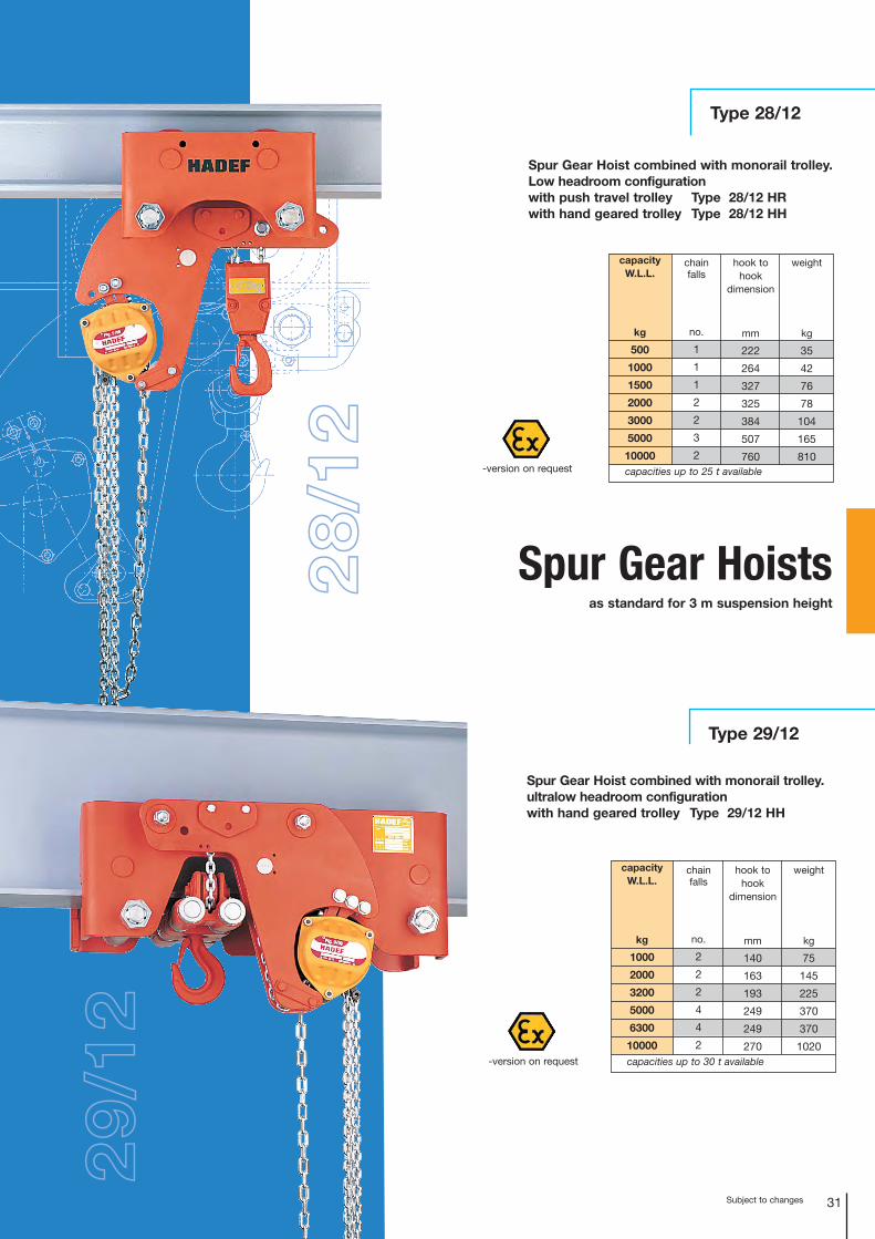
Type 28/12
Type 29/12
Spur Gear Hoistsas standard for 3 m suspension height
Spur Gear Hoist combined with monorail trolley.Low headroom configurationwith push travel trolley Type 28/12 HR with hand geared trolley Type 28/12 HH
capacity W.L.L.
kg
500
1000
1500
2000
3000
5000
10000
chain falls
no.
1
1
1
2
2
3
2
weight
kg
35
42
76
78
104
165
810
hook tohook
dimension
mm
222
264
327
325
384
507
760capacities up to 25 t available
Spur Gear Hoist combined with monorail trolley. ultralow headroom configurationwith hand geared trolley Type 29/12 HH
capacity W.L.L.
kg
1000
2000
3200
5000
6300
10000
chain falls
no.
2
2
2
4
4
2
weight
kg
75
145
225
370
370
1020
hook tohook
dimension
mm
140
163
193
249
249
270capacities up to 30 t available
-version on request
-version on request
28/1
2
29/1
2
32 Subject to changes
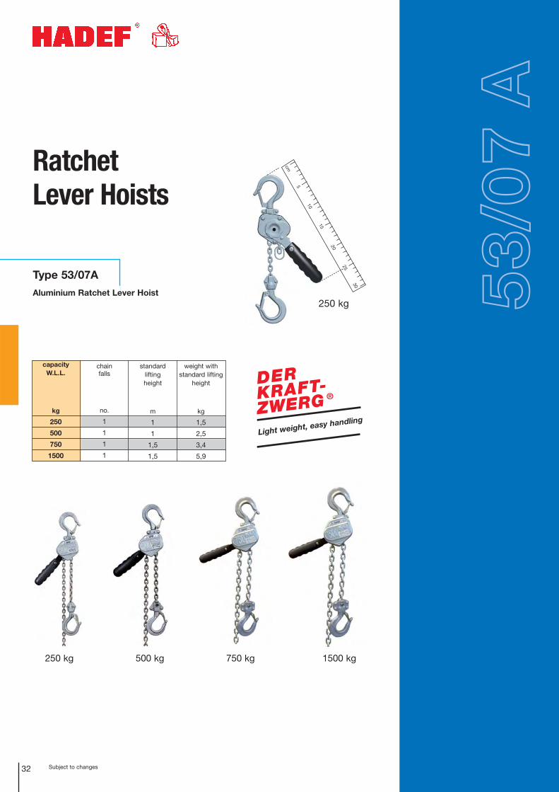
Ratchet Lever Hoists
Type 53/07A
Aluminium Ratchet Lever Hoist 53/0
7 A
250 kg
5
30
cm
25
20
10
15
capacity W.L.L.
kg
250
500
750
1500
chain falls
no.
1
1
1
1
weight with standard lifting
height
kg
1,5
2,5
3,4
5,9
standard lifting height
m
1
1
1,5
1,5
Light weight, easy handling
DERKRAFT-ZWERG ®
250 kg 500 kg 750 kg 1500 kg
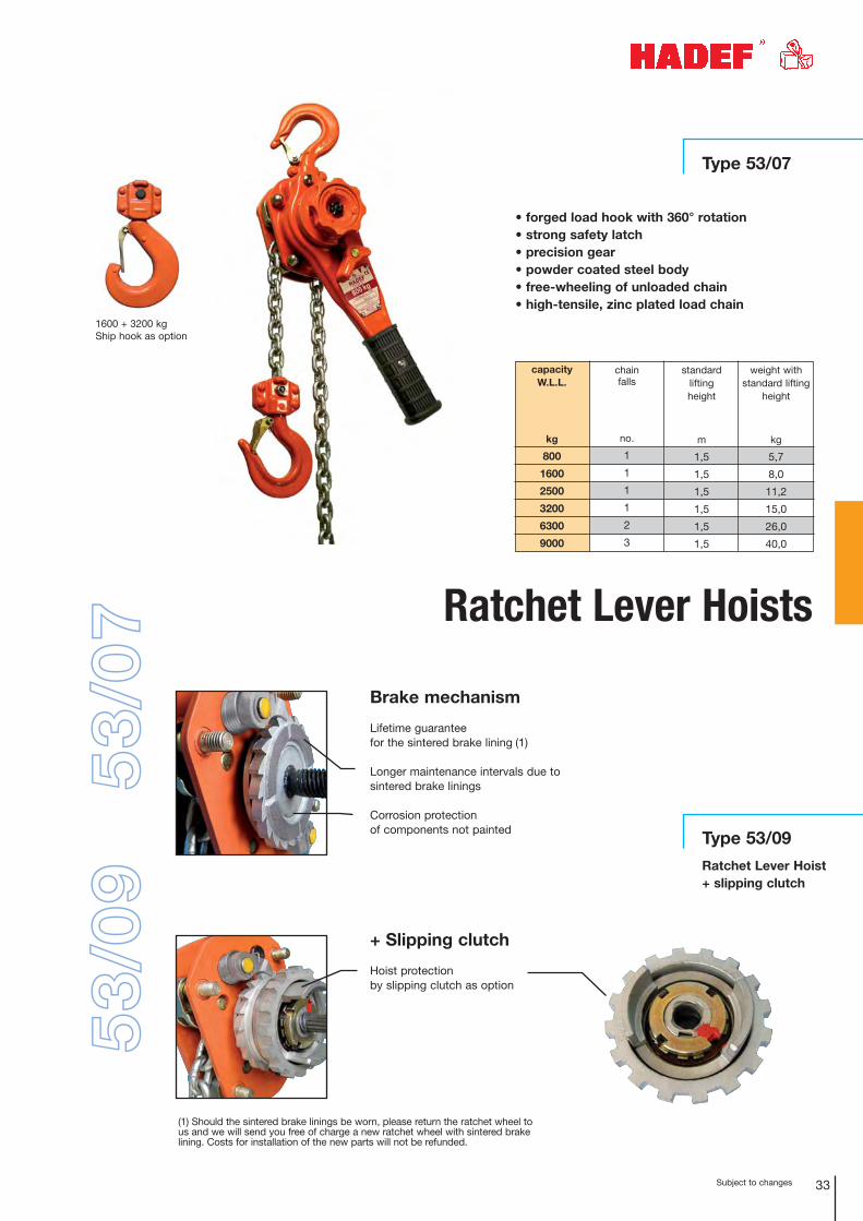
Type 53/07
33Subject to changes
capacity W.L.L.
kg
800
1600
2500
3200
6300
9000
chain falls
no.
1
1
1
1
2
3
weight with standard lifting
height
kg
5,7
8,0
11,2
15,0
26,0
40,0
standard lifting height
m
1,5
1,5
1,5
1,5
1,5
1,5
Ratchet Lever Hoists
Type 53/09
Ratchet Lever Hoist+ slipping clutch
1600 + 3200 kgShip hook as option
53/0
753
/09
+ Slipping clutch
Hoist protection by slipping clutch as option
Brake mechanism
Lifetime guarantee for the sintered brake lining (1)
Longer maintenance intervals due to sintered brake linings
Corrosion protection of components not painted
• forged load hook with 360° rotation• strong safety latch• precision gear• powder coated steel body• free-wheeling of unloaded chain• high-tensile, zinc plated load chain
(1) Should the sintered brake linings be worn, please return the ratchet wheel tous and we will send you free of charge a new ratchet wheel with sintered brakelining. Costs for installation of the new parts will not be refunded.

Subject to changes34
additional high gear ratio
for speed-controlled rope
pay-out
pullingrope force
1st layer
kg
500
drum Ø
mm
82,5
weightwithoutwirerope
kg
10
crank effort
1st layer
daN (kg)
17
4. layer
m
25,0
Ø
mm
6
nec. minimumbreaking
loadkN
18
FEM9.511/
ISO 4301
1Em
wirerope storagewirerope
pullingrope force
1st layer
kg
50
100
weightwithout
wirerope
kg
3
3
5
drum Ø
mm
40
40
46
crank effort
1st layer
daN (kg)
10
12
16
1st layer
m
2,0
2,0
1,4
nec. minimumbreaking
loadkN
3
5
9
FEM9.511/
ISO 4301
1Cm/M2
1Cm/M2
1Cm/M2
pulling rope force
1st layer
kg
63
125
250
Type 199/75Aluminium Wirerope Winch
Type 200/77Wirerope Winch
Type 190/94Type 192/98Stainless Steel Wirerope Winch
Type 430/91Worm Gear Wirerope Winch
wirerope
weightwithout
wirerope
kg
1,0
2,1
crank effort
1st layer
daN (kg)
8
6
1st layer
m
0,4
0,45
Ø
mm
3
3
nec. minimumbreaking
loadkN
2
4
FEM9.511/
ISO 4301
1Cm/M2
1Cm/M2
wirerope storagewirerope
pullingrope force
1st layer
kg
500
drum Ø
mm
82,5
weightwithoutwirerope
kg
11
crank effort
1st layer
daN (kg)
17
4.layer
m
25,0
1stlayer
m
4,9
1st layer
m
4,9
Ø
mm
6
nec. minimumbreaking
loadkN
18
FEM9.511/
ISO 4301
1Em
wirerope storagewirerope
Wirerope winches
Ø
mm
3
3
4
6. layer
m
18,0
18,0
14,0
wirerope storage
weight withoutwirerope
kg
5,5
5,5
5,5
drum Ø
mm
70
70
70
crank effort
1st layer
daN (kg)
5,5
11,5
14
3. layer
m
11,4
8,8
-
1stlayer
m
3,2
2,3
1,8
Ø
mm
3
4
5
pullingrope force
1st layer
kg
125
250
300
wirerope storageFEM9.511/
ISO 4301
1Bm/M3
1Bm/M3
1Bm/M3
nec. minimumbreaking
load
kN
5
9
11
wirerope
6. layer
m
5,3
7,8
Type 190/94
Type 192/98

Subject to changes 35
Type 260/76Manual Spur Gear Wirerope Winch
Steel Jackacc. to DIN 7355
weight without
wirerope
kg
34
50
87
110
drum Ø
mm
120
150
200
205
crank effort
1st layer
daN (kg)
10,3
15,4
16,4
20,3
toplayer
m
42,2
67,4
15,3
13,8
1stlayer
m
4,8
5,2
6,1
5,4
Ø
mm
5
6
9
11
pullingrope
force1st layer
kg
300
500
1000
1500
wireropestorage
wirerope
weight without
wirerope
kg
10
10
15
23
23
drum Ø
mm
70
70
102
120
120
crank effort
1st layer
daN (kg)
19
21
18
32
30
toplayer
m
11,8
11,8
12,0
9,0
7,0
1stlayer
m
2,3
2,3
3,4
4,1
3,0
Ø
mm
6
6
9
12
13
pulling rope force
1st layer
kg
300
500
1000
2000
3000
wireropestorage
weight
kg
13
20
27
42
lift per crank turn
mm
14
8
4
4
crank effort
daN
25
25
25
50
capacity W.L.L.
kg
1500
3000
5000
10000
nec. minimumbreaking
loadkN
11
18
36
54
FEM9.511/
ISO 4301
1Bm/M3
1Bm/M3
1Bm/M3
1Bm/M3
nec.minimumbreaking
loadkN
10
16
32
63
95
FEM9.511/
ISO 4301
1Dm/M1
1Dm/M1
1Dm/M1
1Dm/M1
1Dm/M1
wirerope
lifting height
mm
350
350
350
350
Wirerope winchesType 250/33Wall Winch
optional with load pressure brake or with brake regulator
Type 238/10Worm Gear Wirerope Winch
also available with separating partition for operation with two wireropes
weightwithout
wirerope
kg
13
16
29
28
60
78
117
drum Ø
mm
48
70
102
102
133
165
219
crank effort
daN (kg)
6
10
13
14
12
14
17
toplayer
m
90
63
65
36
58
66
38
1stlayer
m
3
4
5
4
5
6
6
Ø
mm
4
6
8
10
11
14
18
pulling rope force
1st layer
kg
250
500
1000
1500
2000
3000
5000
wireropestorage
wireropenec.
minimumbreaking
loadkN
9
17
34
51
67
101
168
FEM9.511/
ISO 4301
1Cm/M2
1Cm/M2
1Cm/M2
1Dm/M1
1Cm/M2
1Cm/M2
1Cm/M2
Subject to changes36
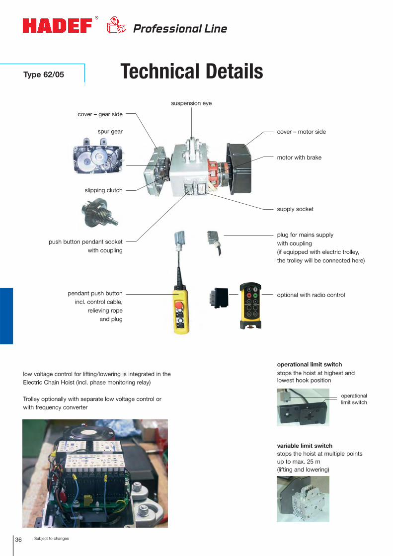
Type 62/05
Professional Line
cover – gear side
spur gear
slipping clutch
push button pendant socket with coupling
pendant push button incl. control cable,
relieving rope and plug
cover – motor side
motor with brake
supply socket
plug for mains supply with coupling(if equipped with electric trolley,the trolley will be connected here)
optional with radio control
operational limit switchstops the hoist at highest and lowest hook position
operationallimit switch
variable limit switchstops the hoist at multiple pointsup to max. 25 m (lifting and lowering)
suspension eye
Technical Details
low voltage control for lifting/lowering is integrated in theElectric Chain Hoist (incl. phase monitoring relay)
Trolley optionally with separate low voltage control or with frequency converter
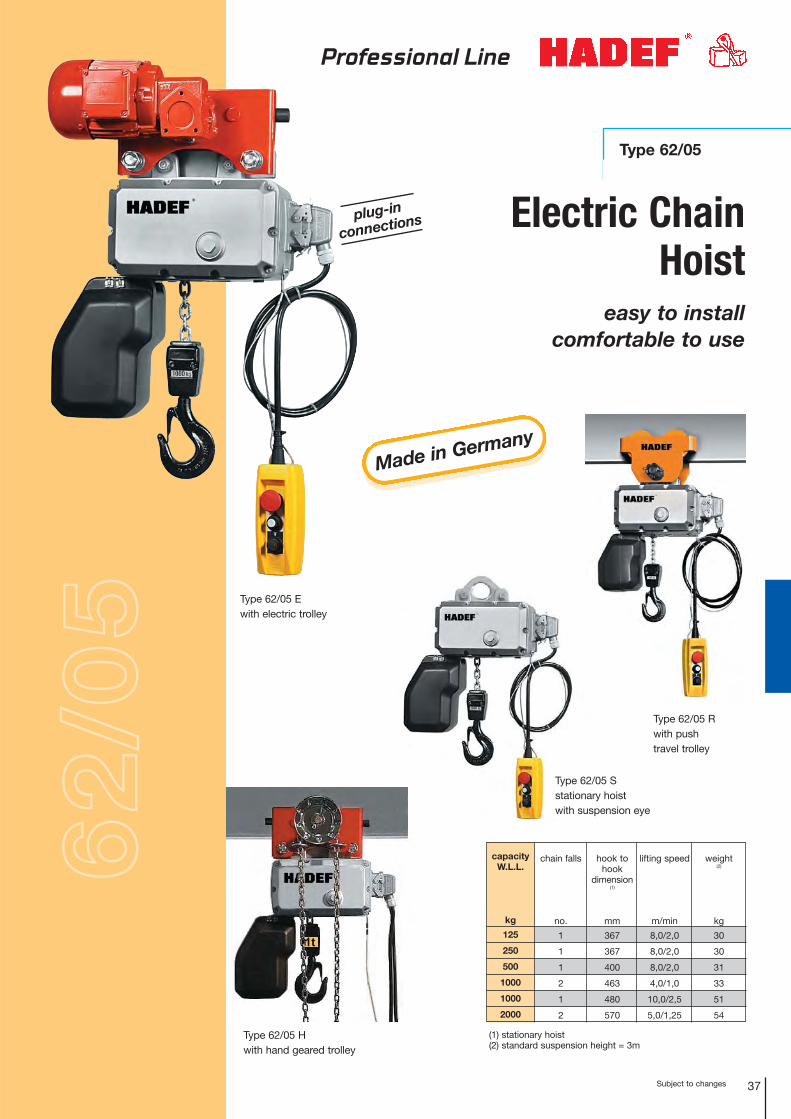
Subject to changes 37
Type 62/05 Rwith push travel trolley
Type 62/05 Hwith hand geared trolley
capacity W.L.L.
kg
125
250
500
1000
1000
2000
chain falls
no.
1
1
1
2
1
2
lifting speed
m/min
8,0/2,0
8,0/2,0
8,0/2,0
4,0/1,0
10,0/2,5
5,0/1,25
hook tohook
dimension(1)
mm
367
367
400
463
480
570
weight(2)
kg
30
30
31
33
51
54
(1) stationary hoist(2) standard suspension height = 3m
Type 62/05 Ewith electric trolley
plug-in
connections
Type 62/05
Type 62/05 Sstationary hoist with suspension eye
Electric ChainHoist
easy to installcomfortable to use
Professional Line
62/0
5
Made in Germany
Type 147/05
WireropePull Hoist
Subject to changes38
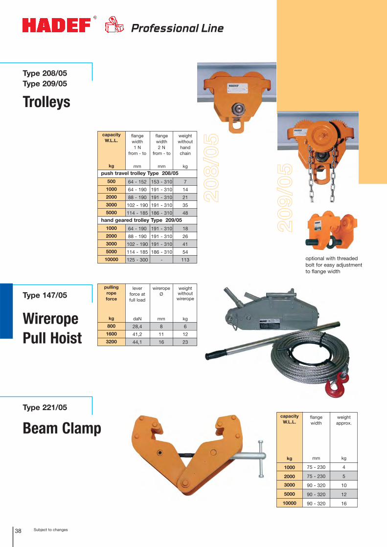
Type 208/05Type 209/05
Trolleys
Type 221/05
Beam Clamp
208/
05
Professional Line
pulling rope force
kg
800
1600
3200
lever force at full load
daN
28,4
41,2
44,1
wireropeØ
mm
8
11
16
weightwithout
wirerope
kg
6
12
23
optional with threadedbolt for easy adjustmentto flange width
209/
05
capacity W.L.L.
kg
500
1000
2000
3000
5000
1000
2000
3000
5000
10000
flangewidth 1 N
from - to
mm
64 - 152
64 - 190
88 - 190
102 - 190
114 - 185
64 - 190
88 - 190
102 - 190
114 - 185
125 - 300
flangewidth 2 N
from - to
mm
153 - 310
191 - 310
191 - 310
191 - 310
186 - 310
191 - 310
191 - 310
191 - 310
186 - 310
-
weightwithouthand chain
kg
7
14
21
35
48
18
26
41
54
113
hand geared trolley Type 209/05
push travel trolley Type 208/05
capacity W.L.L.
kg
1000
2000
3000
5000
10000
flange width
mm
75 - 230
75 - 230
90 - 320
90 - 320
90 - 320
weightapprox.
kg
4
5
10
12
16
Subject to changes 39
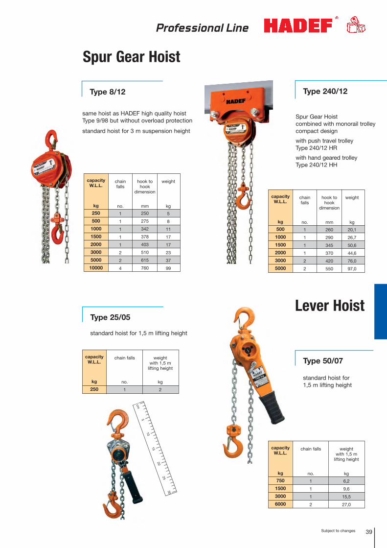
Type 240/12
Spur Gear Hoist
Lever Hoist
chainfalls
no.
1
1
1
1
1
2
2
4
capacity W.L.L.
kg
250
500
1000
1500
2000
3000
5000
10000
hook tohook
dimension
mm
250
275
342
378
403
510
615
760
weight
kg
5
8
11
17
17
23
37
99
chain falls
no.
1
1
1
2
capacity W.L.L.
kg
750
1500
3000
6000
weight with 1,5 m
lifting height
kg
6,2
9,6
15,5
27,0
Type 50/07
standard hoist for 1,5 m lifting height
5
30
cm
25
20
1015
Type 8/12
Spur Gear Hoistcombined with monorail trolleycompact design
with push travel trolleyType 240/12 HR
with hand geared trolleyType 240/12 HH
same hoist as HADEF high quality hoist Type 9/98 but without overload protection
standard hoist for 3 m suspension height
chain falls
no.
1
1
1
1
2
2
capacity W.L.L.
kg
500
1000
1500
2000
3000
5000
hook tohook
dimension
mm
260
290
345
370
420
550
weight
kg
20,1
26,7
50,6
44,6
76,0
97,0
Type 25/05
standard hoist for 1,5 m lifting height
chain falls
no.
1
capacity W.L.L.
kg
250
weight with 1,5 m
lifting height
kg
2
Professional Line
Subject to changes40
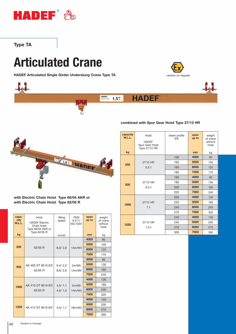
Type TA
Articulated CraneHADEF Articulated Single Girder Underslung Crane Type TA
span up to
mm
4000
5000
6000
7000
4000
5000
6000
7000
4000
5000
6000
7000
4000
5000
6000
7000
Hoist
HADEF Electric Chain Hoist
Type 66/04 AKR orType 62/05 R
62/05 R
AK 405 DT 80 N 8/2
62/05 R
AK 410 DT 80 N 8/2
62/05 R
AK 412 DT 80 N 8/2
capa-city
W.L.L.
kg
250
500
1000
1250
FEM 9.511/
ISO 4301
1Am/M4
2m/M5
1Am/M4
2m/M5
1Am/M4
1Bm/M3
lifting speed
m/min
8,0/ 2,0
9,4/ 2,3
8,0/ 2,0
4,5/ 1,1
4,0/ 1,0
4,5/ 1,1
with Electric Chain Hoist Type 66/04 AKR orwith Electric Chain Hoist Type 62/05 R
weight of cranewithout
hoist
kg
90
105
125
170
90
130
180
240
130
180
240
320
150
200
270
360
-version on request
combined with Spur Gear Hoist Type 27/12 HR
span up to
mm
4000
5000
6000
7000
4000
5000
6000
7000
4000
5000
6000
7000
4000
5000
6000
7000
weight of cranewithout
hoist
kg
90
105
125
170
90
130
180
240
130
180
240
320
150
200
270
360
Hoist
HADEF Spur Gear Hoist Type 27/12 HR
27/12 HR
0,5 t
27/12 HR
0,5 t
27/12 HR
1 t
27/12 HR
1,5 t
capacityW.L.L.
kg
250
500
1000
1250
beam profile IPE
160
160
160
180
160
180
200
220
200
220
240
270
240
240
270
300
41Subject to changes
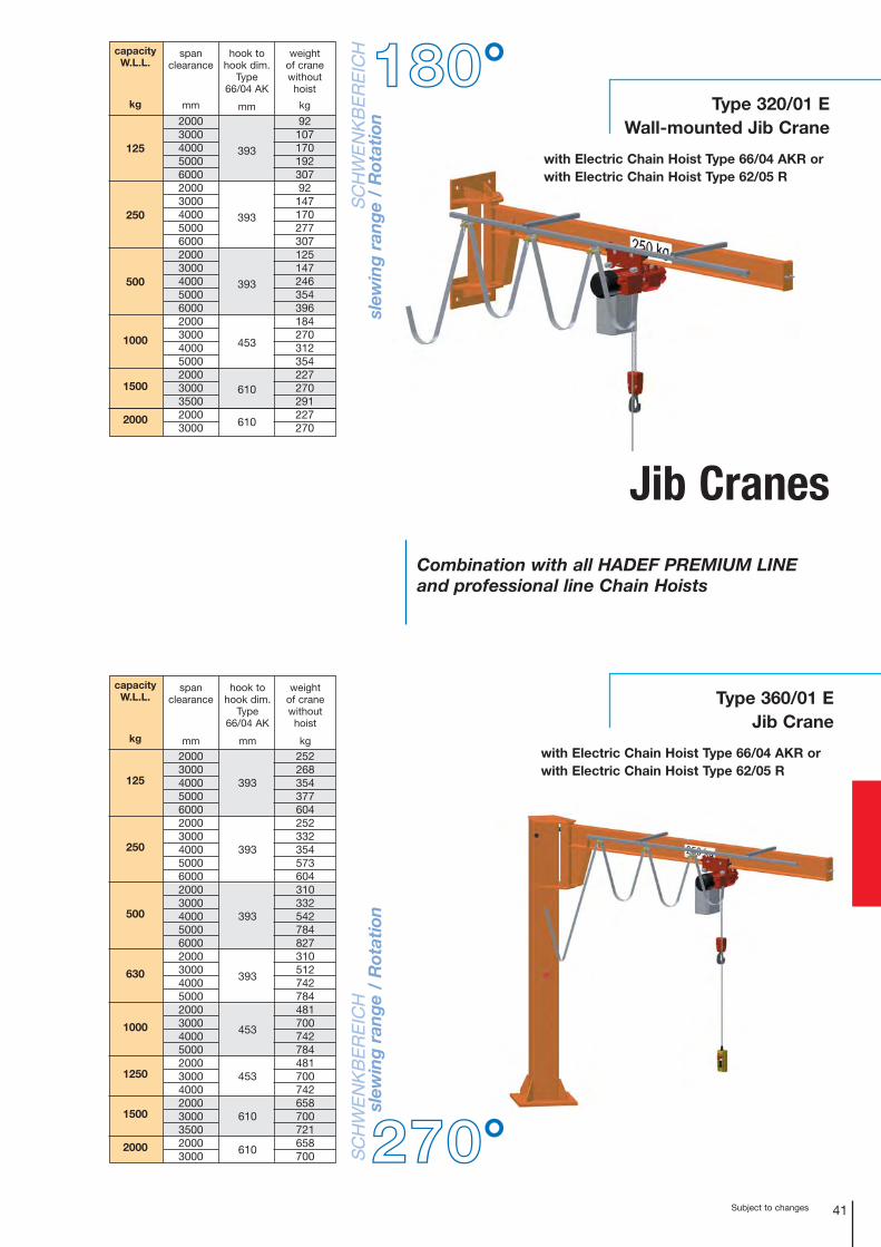
Type 320/01 EWall-mounted Jib Crane
Jib Cranes
Combination with all HADEF PREMIUM LINEand professional line Chain Hoists
with Electric Chain Hoist Type 66/04 AKR or with Electric Chain Hoist Type 62/05 R
Type 360/01 EJib Crane
with Electric Chain Hoist Type 66/04 AKR or with Electric Chain Hoist Type 62/05 R
weight of cranewithout
hoist
kg
252268354377604252332354573604310332542784827310512742784481700742784481700742658700721658700
capacity W.L.L.
kg
125
250
500
630
1000
1250
1500
2000
span clearance
mm
2000300040005000600020003000400050006000200030004000500060002000300040005000200030004000500020003000400020003000350020003000
hook tohook dim.
Type66/04 AK
mm
393
393
393
393
453
453
610
610
180°
270°
weight of cranewithout
hoist
kg
9210717019230792
147170277307125147246354396184270312354227270291227270
capacity W.L.L.
kg
125
250
500
1000
1500
2000
span clearance
mm
200030004000500060002000300040005000600020003000400050006000200030004000500020003000350020003000
hook tohook dim.
Type66/04 AK
mm
393
393
393
453
610
610
SC
HW
EN
KB
ER
EIC
Hsl
ewin
g r
ang
e /
Rot
atio
nS
CH
WE
NK
BE
RE
ICH
slew
ing
ran
ge
/ R
otat
ion
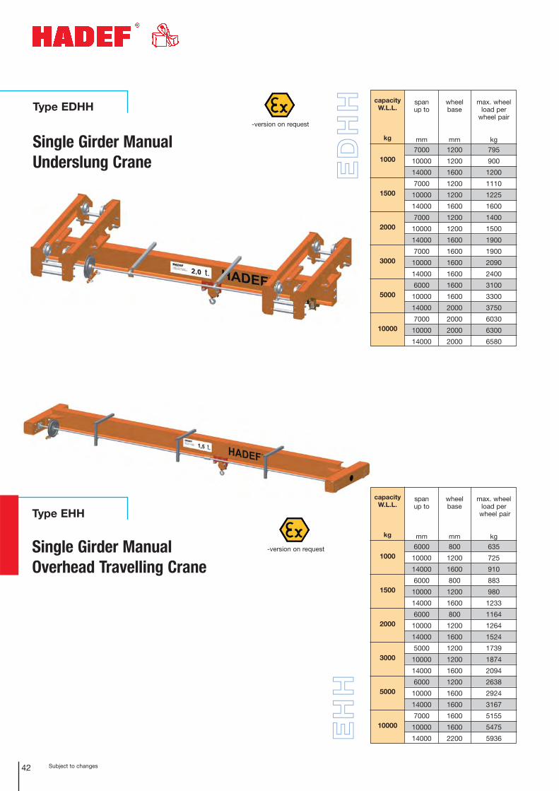
Type EHH
Single Girder ManualOverhead Travelling Crane
EH
H
Subject to changes42
Type EDHH
Single Girder ManualUnderslung Crane
capacity W.L.L.
kg
1000
1500
2000
3000
5000
10000
max. wheelload per
wheel pair
kg
795
900
1200
1110
1225
1600
1400
1500
1900
1900
2090
2400
3100
3300
3750
6030
6300
6580
span up to
mm
7000
10000
14000
7000
10000
14000
7000
10000
14000
7000
10000
14000
6000
10000
14000
7000
10000
14000
wheelbase
mm
1200
1200
1600
1200
1200
1600
1200
1200
1600
1600
1600
1600
1600
1600
2000
2000
2000
2000
capacity W.L.L.
kg
1000
1500
2000
3000
5000
10000
max. wheelload per
wheel pair
kg
635
725
910
883
980
1233
1164
1264
1524
1739
1874
2094
2638
2924
3167
5155
5475
5936
span up to
mm
6000
10000
14000
6000
10000
14000
6000
10000
14000
5000
10000
14000
6000
10000
14000
7000
10000
14000
wheelbase
mm
800
1200
1600
800
1200
1600
800
1200
1600
1200
1200
1600
1200
1600
1600
1600
1600
2200
ED
HH
-version on request
-version on request
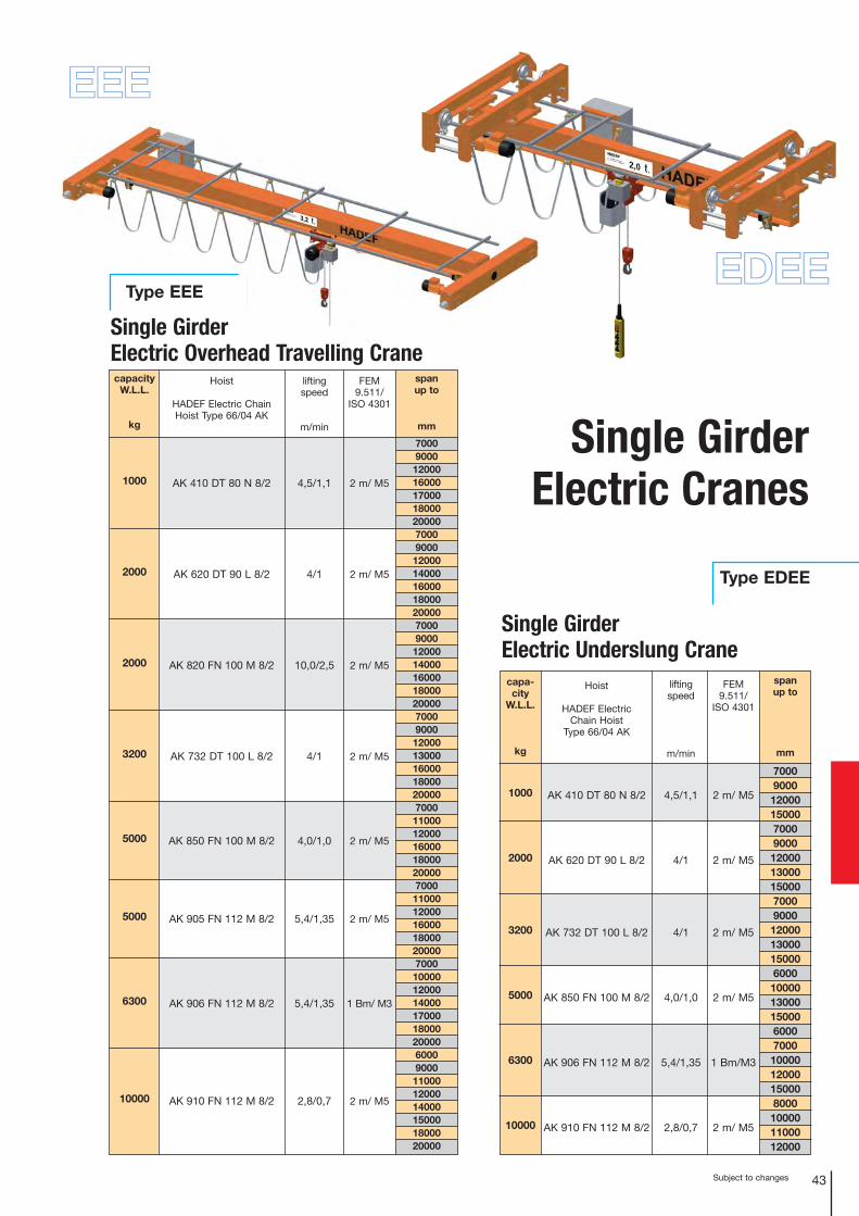
EEE
Type EEE
Subject to changes 43
Single GirderElectric Cranes
EDEE
Type EDEE
Single Girder Electric Underslung Crane
capacity W.L.L.
kg
1000
2000
2000
3200
5000
5000
6300
10000
Hoist
HADEF Electric ChainHoist Type 66/04 AK
AK 410 DT 80 N 8/2
AK 620 DT 90 L 8/2
AK 820 FN 100 M 8/2
AK 732 DT 100 L 8/2
AK 850 FN 100 M 8/2
AK 905 FN 112 M 8/2
AK 906 FN 112 M 8/2
AK 910 FN 112 M 8/2
lifting speed
m/min
4,5/1,1
4/1
10,0/2,5
4/1
4,0/1,0
5,4/1,35
5,4/1,35
2,8/0,7
FEM9.511/
ISO 4301
2 m/ M5
2 m/ M5
2 m/ M5
2 m/ M5
2 m/ M5
2 m/ M5
1 Bm/ M3
2 m/ M5
span up to
mm
70009000
120001600017000180002000070009000
120001400016000180002000070009000
120001400016000180002000070009000
12000130001600018000200007000
11000120001600018000200007000
11000120001600018000200007000
10000120001400017000180002000060009000
110001200014000150001800020000
capa-city
W.L.L.
kg
1000
2000
3200
5000
6300
10000
span up to
mm
70009000
120001500070009000
12000130001500070009000
1200013000150006000
10000130001500060007000
1000012000150008000
100001100012000
Hoist
HADEF Electric Chain Hoist
Type 66/04 AK
AK 410 DT 80 N 8/2
AK 620 DT 90 L 8/2
AK 732 DT 100 L 8/2
AK 850 FN 100 M 8/2
AK 906 FN 112 M 8/2
AK 910 FN 112 M 8/2
FEM9.511/
ISO 4301
2 m/ M5
2 m/ M5
2 m/ M5
2 m/ M5
1 Bm/M3
2 m/ M5
liftingspeed
m/min
4,5/1,1
4/1
4/1
4,0/1,0
5,4/1,35
2,8/0,7
Single GirderElectric Overhead Travelling Crane
Subject to changes44
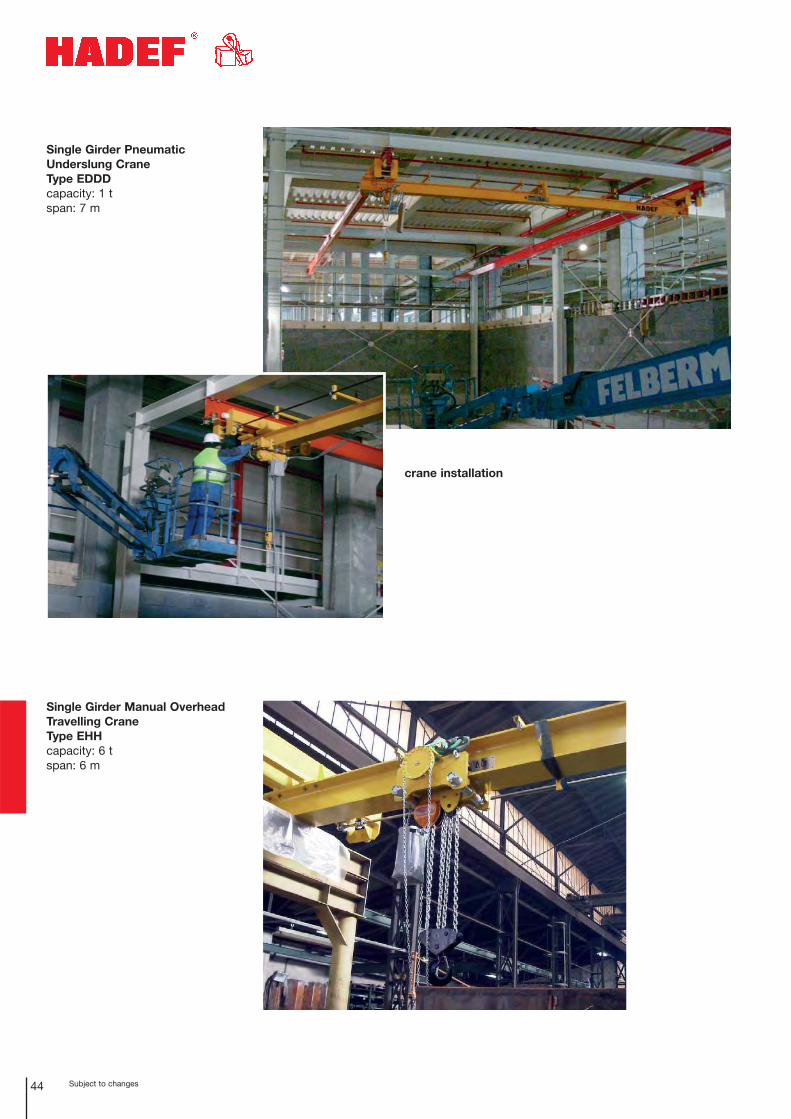
Single Girder Pneumatic Underslung CraneType EDDDcapacity: 1 tspan: 7 m
Single Girder Manual OverheadTravelling CraneType EHHcapacity: 6 tspan: 6 m
crane installation

Subject to changes 45
HADEF gantry cranewith ultralow headroomElectric Chain HoistType 29/06 EEcapacity: 5 t
Adapter Craneswithout main beam
End Carriages
Articulated Single Girder Underslung Crane Type TA
Single Girder Manual Overhead Travelling Crane Type EHH
Single Girder Manual Underslung Crane Type EDHH
Single Girder Electric Overhead Travelling Crane Type EEE
Single Girder Electric Underslung Crane Type EDEE
Save costs!HADEF Adapter Cranes help toreduce expensive cost fortransport as the componentsare supplied and the mainbeam can be bought nearbyand installed on site.
ultralow
headroom
hoist
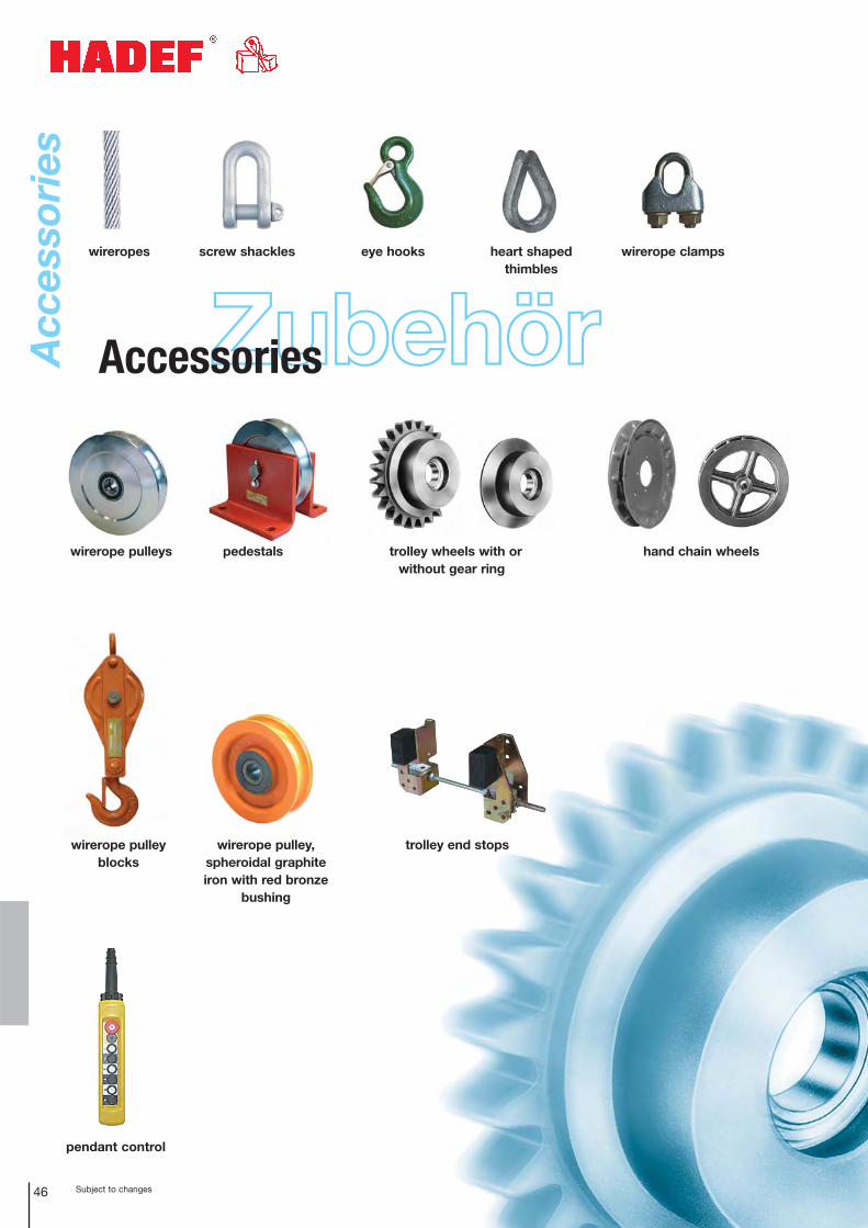
wireropes screw shackles eye hooks heart shapedthimbles
wirerope clamps
wirerope pulleys
wirerope pulleyblocks
wirerope pulley,spheroidal graphiteiron with red bronze
bushing
pendant control
trolley end stops
pedestals trolley wheels with or without gear ring
hand chain wheels
ZubehörAccessoriesAcc
esso
ries
Subject to changes46
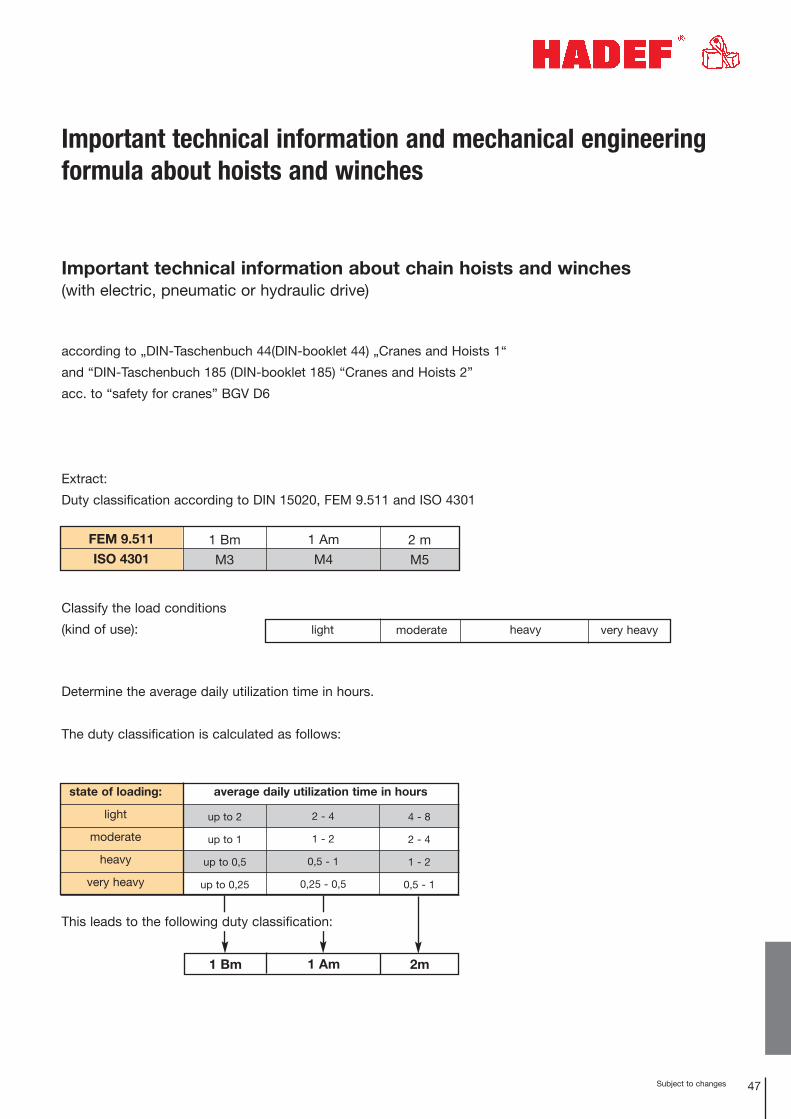
Important technical information about chain hoists and winches (with electric, pneumatic or hydraulic drive)
according to „DIN-Taschenbuch 44(DIN-booklet 44) „Cranes and Hoists 1“
and “DIN-Taschenbuch 185 (DIN-booklet 185) “Cranes and Hoists 2”
acc. to “safety for cranes” BGV D6
Extract:
Duty classification according to DIN 15020, FEM 9.511 and ISO 4301
Determine the average daily utilization time in hours.
The duty classification is calculated as follows:
This leads to the following duty classification:
Subject to changes 47
state of loading:
light
moderate
heavy
very heavy
up to 2
up to 1
up to 0,5
up to 0,25
4 - 8
2 - 4
1 - 2
0,5 - 1
2 - 4
1 - 2
0,5 - 1
0,25 - 0,5
average daily utilization time in hours
FEM 9.511
ISO 43011 Bm
M3
2 m
M5
1 Am
M4
light moderate very heavyheavy
1 Bm 1 Am 2m
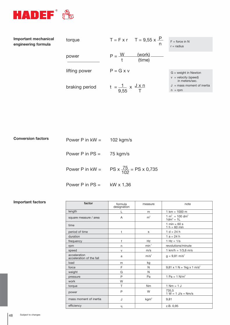
Important technical information and mechanical engineeringformula about hoists and winches
Classify the load conditions
(kind of use):
48 Subject to changes
torque T = F x r T = 9,55 x P n
power P = W (work) t (time)
lifting power P = G x v
braking period t = 1 x J x n9,55 T
Power P in kW = 102 kgm/s
Power P in PS = 75 kgm/s
Power P in kW = PS x 75 = PS x 0,735102
Power P in PS = kW x 1,36
Conversion factors
Important mechanicalengineering formula
Important factors factor
length
square measure / area
time
period of time
duration
frequency
rpm
speed
accelerationacceleration of the fall
load
force
weight
pressure
work
torque
power
mass moment of inertia
efficiency
formula designation
L
A
t
f
n
v
a
m
F
G
P
W
T
P
J
η
measure
m
m2
s
Hz
min-1
m/s
m/s2
kg
N
N
Pa
Nm
W
kgm2
note
1 km = 1000 m
1 m2 = 100 dm2
1dm3 = 1L
1 min = 60 s1 h = 60 min
1 d = 24 h
1 a = 24 h
1 Hz = 1/s
revolutions/minute
1 km/h = 1/3,6 m/s
g = 9,81 m/s2
9,81 x 1 N = 1kg x 1 m/s2
1 Pa = 1 N/m2
1 Nm = 1 J
735,51 W = 1 J/s = Nm/s
9,81
z.B. 0,95
F = force in N
r = radius
G = weight in Newton
v = velocity (speed) in meters/sec.
J = mass moment of inertia
n = rpm
49Subject to changes
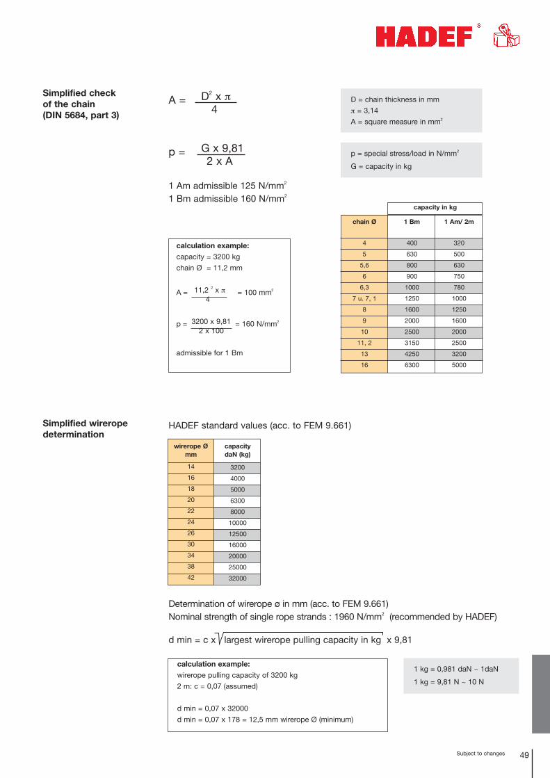
A = D2 x π4
p = G x 9,812 x A
1 Am admissible 125 N/mm2
1 Bm admissible 160 N/mm2
Simplified check of the chain (DIN 5684, part 3)
Simplified wireropedetermination
HADEF standard values (acc. to FEM 9.661)
D = chain thickness in mm
π = 3,14
A = square measure in mm2
p = special stress/load in N/mm2
G = capacity in kg
chain Ø
4
5
5,6
6
6,3
7 u. 7, 1
8
9
10
11, 2
13
16
1 Am/ 2m
320
500
630
750
780
1000
1250
1600
2000
2500
3200
5000
capacity in kg
1 Bm
400
630
800
900
1000
1250
1600
2000
2500
3150
4250
6300
calculation example:
capacity = 3200 kg
chain Ø = 11,2 mm
A = 11,2 2 x π = 100 mm2
4
p = 3200 x 9,81 = 160 N/mm2
2 x 100
admissible for 1 Bm
Determination of wirerope ø in mm (acc. to FEM 9.661)Nominal strength of single rope strands : 1960 N/mm2 (recommended by HADEF)
d min = c x largest wirerope pulling capacity in kg x 9,81
wirerope Ø mm
14
16
18
20
22
24
26
30
34
38
42
capacity daN (kg)
3200
4000
5000
6300
8000
10000
12500
16000
20000
25000
32000
calculation example:
wirerope pulling capacity of 3200 kg
2 m: c = 0,07 (assumed)
d min = 0,07 x 32000
d min = 0,07 x 178 = 12,5 mm wirerope Ø (minimum)
1 kg = 0,981 daN ~ 1daN
1 kg = 9,81 N ~ 10 N
50 Subject to changes
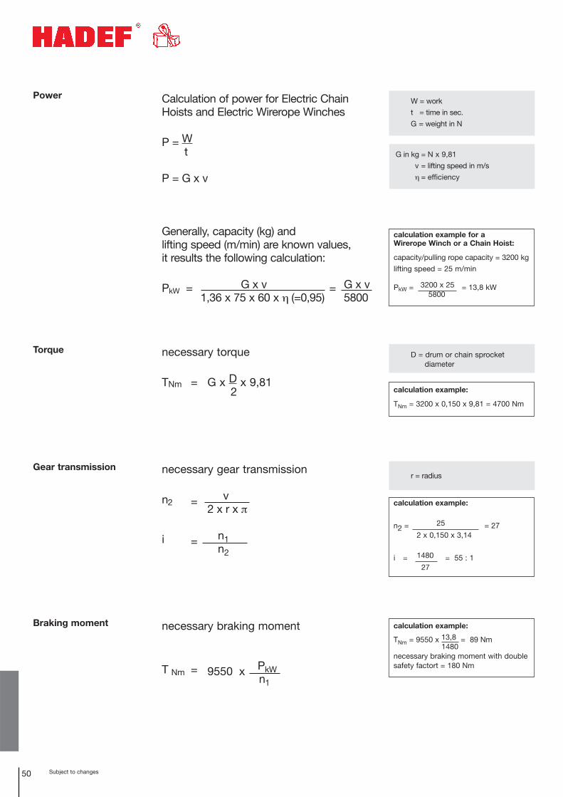
Power Calculation of power for Electric Chain Hoists and Electric Wirerope Winches
P = Wt
P = G x v
Generally, capacity (kg) and lifting speed (m/min) are known values, it results the following calculation:
PkW = G x v = G x v1,36 x 75 x 60 x η (=0,95) 5800
necessary torque
TNm = G x D x 9,812
W = work
t = time in sec.
G = weight in N
D = drum or chain sprocket diameter
G in kg = N x 9,81
v = lifting speed in m/s
η = efficiency
calculation example for a Wirerope Winch or a Chain Hoist:
capacity/pulling rope capacity = 3200 kg
lifting speed = 25 m/min
PkW = 3200 x 25 = 13,8 kW5800
Torque
calculation example:
TNm = 3200 x 0,150 x 9,81 = 4700 Nm
necessary gear transmission
n2 = v2 x r x π
i = n1n2
r = radiusGear transmission
calculation example:
n2 = 25 = 272 x 0,150 x 3,14
i = 1480 = 55 : 127
necessary braking moment
T Nm = 9550 x PkWn1
Braking moment calculation example:
TNm = 9550 x 13,8 = 89 Nm1480
necessary braking moment with doublesafety factort = 180 Nm
51Subject to changes
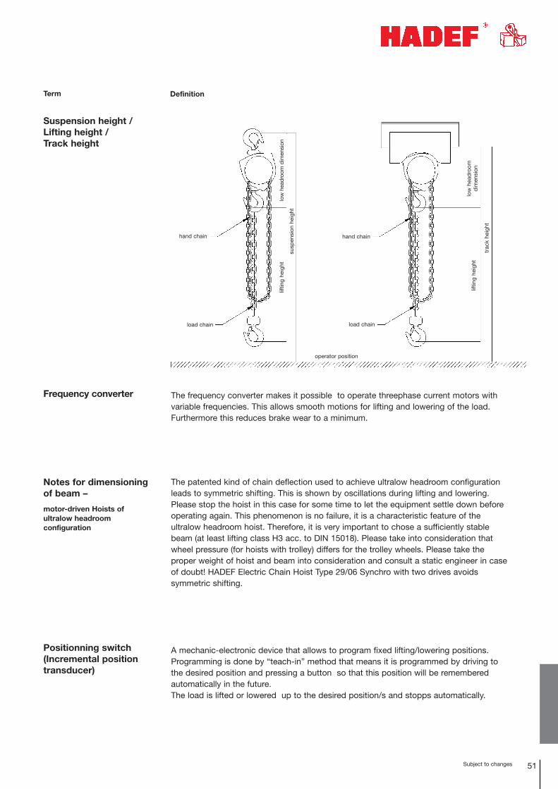
Suspension height /Lifting height / Track height
hand chain
load chain load chain
operator position
liftin
g he
ight
lo
w h
eadr
oom
dim
ensi
on
low
hea
dro
omd
imen
sion
liftin
g he
ight
trac
k he
ight
susp
ensi
on h
eigh
t
hand chain
Term Definition
Frequency converter
Positionning switch (Incremental positiontransducer)
Notes for dimensioningof beam –
motor-driven Hoists of ultralow headroom configuration
The frequency converter makes it possible to operate threephase current motors with variable frequencies. This allows smooth motions for lifting and lowering of the load. Furthermore this reduces brake wear to a minimum.
The patented kind of chain deflection used to achieve ultralow headroom configurationleads to symmetric shifting. This is shown by oscillations during lifting and lowering.Please stop the hoist in this case for some time to let the equipment settle down beforeoperating again. This phenomenon is no failure, it is a characteristic feature of the ultralow headroom hoist. Therefore, it is very important to chose a sufficiently stablebeam (at least lifting class H3 acc. to DIN 15018). Please take into consideration thatwheel pressure (for hoists with trolley) differs for the trolley wheels. Please take the proper weight of hoist and beam into consideration and consult a static engineer in caseof doubt! HADEF Electric Chain Hoist Type 29/06 Synchro with two drives avoids symmetric shifting.
A mechanic-electronic device that allows to program fixed lifting/lowering positions.Programming is done by “teach-in” method that means it is programmed by driving tothe desired position and pressing a button so that this position will be remembered automatically in the future.The load is lifted or lowered up to the desired position/s and stopps automatically.
52 Subject to changes
1) source: Extract from the UVV (accident prevention regulations) for Cranes (BGV D6)
Phase monitoring relay
Term Definition
This device assures correct connection of the motor to the threephase current netand thus prevents the hoist from damage. This is very important for hoists that areused not only at one single area but at different places and are therefore movedand connected again. In case of wrong connection or phase failure the phasemonitoring relay prevents operation of the hoist.
Inspection before firstcommissioning
Testing before first commissioning concerns correct installation, equipment andreadiness for operation. It consists of preliminary test, manufacturing test andapproval test. Inspection before first commissioning is not necessary when thecrane is supplied ready for operation and a certificate of homologation or a certificate of EU-Conformity is available for the crane.
Testing of Cranes 1)It is up to the responsibility of the user to make sure that power-driven cranes aretested by an expert prior to first commissioning and after substantial changes before putting them into operation again. Sentence no. 1 also applies to manual orpartly-power-driven cranes with a capacity of more than 1000 kg.
Recurring inspection It is up to the responsibility of the user to have cranes tested by an expert, inaccordance with their service and working conditions but at least once a year. Theinstructions of the manufacturer regarding testing must be observed. Test resultsmust be written down in a test book. The test book must be shown on demand.
Low voltage control This device guarantees safe operation of high-performance motors. A control transformer reduces the control voltage to ≥ 50 V and thus protects the operator fromhigh voltage. The pendant control only carries control voltage and not the entire net voltage (i.e. 400 V). Furthermore, hoists with low voltage control can easily be backfittedwith limit switches for lifting or travel.
Term Definition
Insulation Classes Insulation Classes – Temperature limitsThe Insulation Classes indicate the maximum temperatures that are allowed for themotor windings inside the stator. Motor size and power depend on the Insulationclass required.
The HADEF Premium Line Electric Chain Hoist Series AK with low voltagecontrol is fitted with thermal protection that cuts-off the motor when the max.permitted temperature is reached.
Example: Should the max. motor temperature of 155 °C (Insulation class F) bereduced to 130 °C (Insulation class B) a motor of bigger size must be selected toachieve this.
HADEF Electric Chain Hoists are classified for Insulation class F.
The temperature rise for motor windings must not exceed the following values:
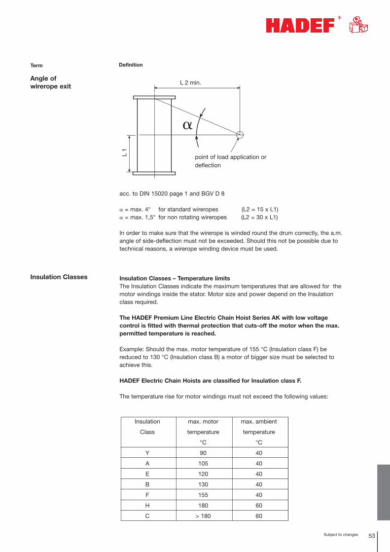
Angle of wirerope exit
acc. to DIN 15020 page 1 and BGV D 8
� = max. 4° for standard wireropes (L2 = 15 x L1)� = max. 1,5° for non rotating wireropes (L2 = 30 x L1)
In order to make sure that the wirerope is winded round the drum correctly, the a.m.angle of side-deflection must not be exceeded. Should this not be possible due totechnical reasons, a wirerope winding device must be used.
L 1
L 2 min.
Lastangriffs- bzw.Umlenkpunkt
53Subject to changes
point of load application ordeflection
Insulation max. motor max. ambient
Class temperature temperature
°C °C
Y 90 40
A 105 40
E 120 40
B 130 40
F 155 40
H 180 60
C > 180 60
54 Subject to changes
Term Definition
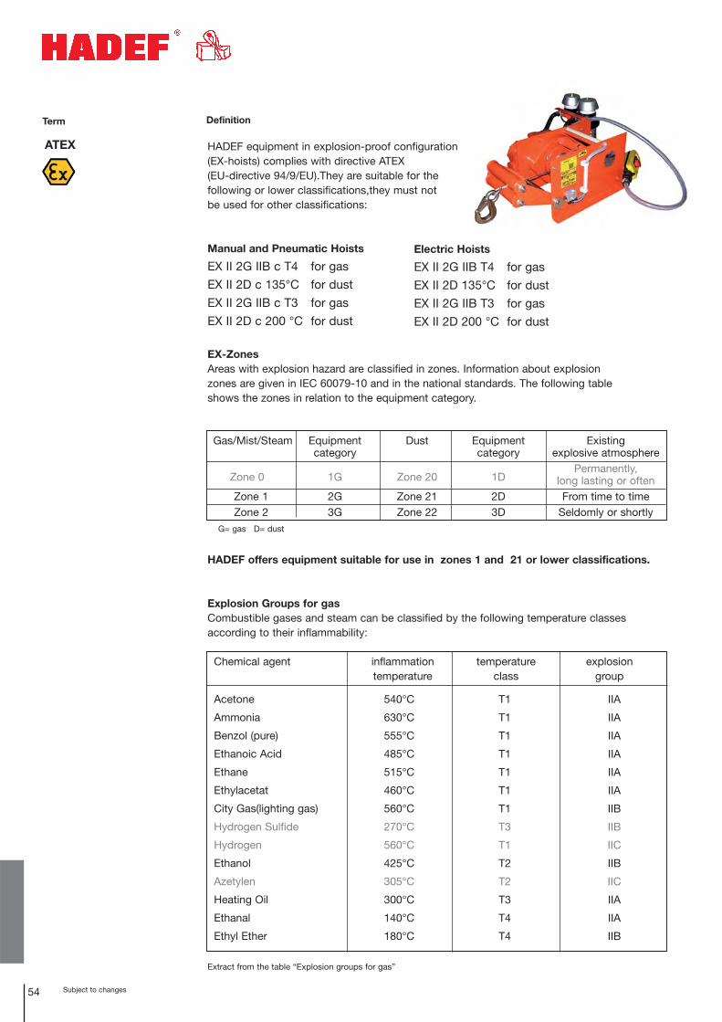
ATEX HADEF equipment in explosion-proof configuration (EX-hoists) complies with directive ATEX (EU-directive 94/9/EU).They are suitable for the following or lower classifications,they must not be used for other classifications:
Manual and Pneumatic Hoists
EX II 2G IIB c T4 for gas
EX II 2D c 135°C for dust
EX II 2G IIB c T3 for gas
EX II 2D c 200 °C for dust
EX-ZonesAreas with explosion hazard are classified in zones. Information about explosionzones are given in IEC 60079-10 and in the national standards. The following tableshows the zones in relation to the equipment category.
HADEF offers equipment suitable for use in zones 1 and 21 or lower classifications.
Explosion Groups for gasCombustible gases and steam can be classified by the following temperature classes according to their inflammability:
Extract from the table “Explosion groups for gas”
Gas/Mist/Steam Equipment Dust Equipment Existing category category explosive atmosphere
Zone 0 1G Zone 20 1DPermanently,
long lasting or often Zone 1 2G Zone 21 2D From time to timeZone 2 3G Zone 22 3D Seldomly or shortly
G= gas D= dust
Chemical agent inflammation temperature explosion temperature class group
Acetone
Ammonia
Benzol (pure)
Ethanoic Acid
Ethane
Ethylacetat
City Gas(lighting gas)
Hydrogen Sulfide
Hydrogen
Ethanol
Azetylen
Heating Oil
Ethanal
Ethyl Ether
540°C
630°C
555°C
485°C
515°C
460°C
560°C
270°C
560°C
425°C
305°C
300°C
140°C
180°C
T1
T1
T1
T1
T1
T1
T1
T3
T1
T2
T2
T3
T4
T4
IIA
IIA
IIA
IIA
IIA
IIA
IIB
IIB
IIC
IIB
IIC
IIA
IIA
IIB
Electric Hoists
EX II 2G IIB T4 for gas
EX II 2D 135°C for dust
EX II 2G IIB T3 for gas
EX II 2D 200 °C for dust
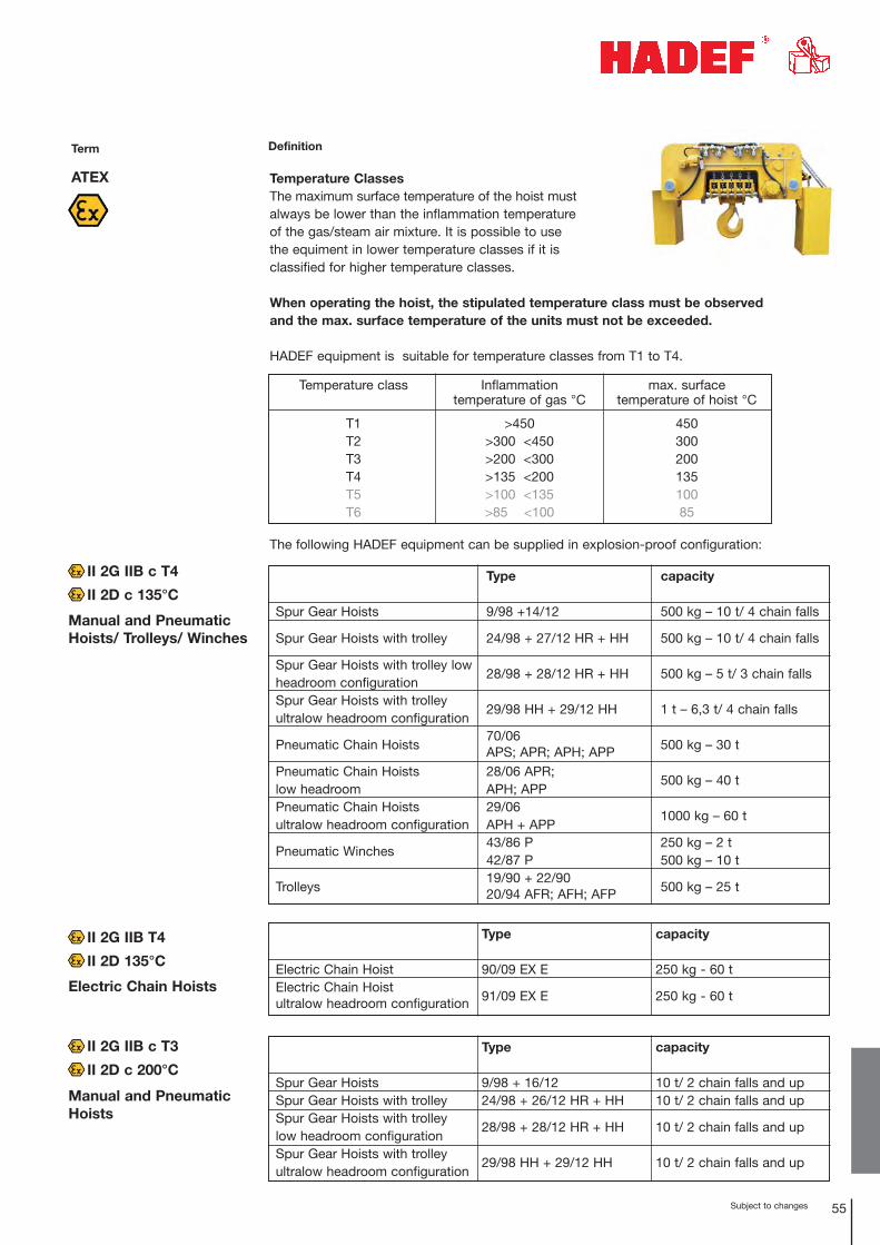
55Subject to changes
ATEX
Term
Manual and PneumaticHoists/ Trolleys/ Winches
Electric Chain Hoists
Manual and PneumaticHoists
Definition
Temperature ClassesThe maximum surface temperature of the hoist mustalways be lower than the inflammation temperature of the gas/steam air mixture. It is possible to use the equiment in lower temperature classes if it is classified for higher temperature classes.
When operating the hoist, the stipulated temperature class must be observed and the max. surface temperature of the units must not be exceeded.
HADEF equipment is suitable for temperature classes from T1 to T4.
The following HADEF equipment can be supplied in explosion-proof configuration:
Temperature class
T1T2T3T4T5T6
Inflammation temperature of gas °C
>450>300 <450>200 <300>135 <200>100 <135>85 <100
max. surface temperature of hoist °C
45030020013510085
Spur Gear Hoists
Spur Gear Hoists with trolley
Spur Gear Hoists with trolley lowheadroom configurationSpur Gear Hoists with trolleyultralow headroom configuration
Pneumatic Chain Hoists
Pneumatic Chain Hoistslow headroom Pneumatic Chain Hoistsultralow headroom configuration
Pneumatic Winches
Trolleys
Type
9/98 +14/12
24/98 + 27/12 HR + HH
28/98 + 28/12 HR + HH
29/98 HH + 29/12 HH
70/06 APS; APR; APH; APP28/06 APR;APH; APP29/06 APH + APP43/86 P42/87 P19/90 + 22/9020/94 AFR; AFH; AFP
capacity
500 kg – 10 t/ 4 chain falls
500 kg – 10 t/ 4 chain falls
500 kg – 5 t/ 3 chain falls
1 t – 6,3 t/ 4 chain falls
500 kg – 30 t
500 kg – 40 t
1000 kg – 60 t
250 kg – 2 t500 kg – 10 t
500 kg – 25 t
Spur Gear HoistsSpur Gear Hoists with trolleySpur Gear Hoists with trolley low headroom configurationSpur Gear Hoists with trolley ultralow headroom configuration
Type
9/98 + 16/1224/98 + 26/12 HR + HH
28/98 + 28/12 HR + HH
29/98 HH + 29/12 HH
capacity
10 t/ 2 chain falls and up10 t/ 2 chain falls and up
10 t/ 2 chain falls and up
10 t/ 2 chain falls and up
II 2G IIB c T4
II 2D c 135°C
II 2G IIB c T3
II 2D c 200°C
Electric Chain HoistElectric Chain Hoistultralow headroom configuration
Type
90/09 EX E
91/09 EX E
capacity
250 kg - 60 t
250 kg - 60 t
II 2G IIB T4
II 2D 135°C

© 2
013
Tesc
hner
´s A
telie
r .
Bar
uth