Embed Size (px)
Citation preview

HOH AGRI (PTY) LTD.
GREENTASTIC
CONTROLLED ENVIRONMENT AGRICULTURAL
(CEA) FARMING OPERATION, HYDROPONIC
PRODUCTION & PACKAGING FACILITY, ATLANTIS
33526.00-REP-002 REV 1 - DRAFT
CIVIL BULK SERVICES REPORT
NOVEMBER 2020
PREPARED FOR:
PREPARED BY:
HOH AGRI (Pty) Ltd.
GLOBAL AGRICULTURAL HOLDINGS
CONTROLLED ENVIRONMENT AGRICULTURAL
(CEA) FARMING OPERATION, ATLANTIS
8 ROBINSON WAY
EDGEMAD, CAPE TOWN
7441
BVi CONSULTING ENGINEERS WC (PTY) LTD
EDISON SQUARE, C/O EDISON WAY & CENTURY
AVENUE, CENTURY CITY
7441

GREENTASTIC - GREENHOUSE HYDROPONIC PRODUCTION & PACKAGING FACILITY
Page i
33526.00-REP002-PDR Rev1-DRAFT
ISSUE & REVISION RECORD
QUALITY APPROVAL
Capacity Name Signature Date
By Author Design Engineer Francois Greeff
09/11/2020
Approved by
Design Centre
Leader
Project Director Sampie Laubscher 09/11/2020
This report has been prepared in accordance with BVi Consulting Engineers
Quality Management System. BVi Consulting Engineers is ISO 9001: 2015
registered and certified by NQA Africa.
REVISION RECORD
Revision
Number Objective Change Date
0 Issue to PM & Environmental
Consultant for comments None 28/10/2020
1
Draft - Issue to PM &
Environmental Consultant for
comments
Updated Water balancing & demand info 09/11/2020

GREENTASTIC - GREENHOUSE HYDROPONIC PRODUCTION & PACKAGING FACILITY
Page ii
33526.00-REP002-PDR Rev1-DRAFT
EXECUTIVE SUMMARY
BVi Consulting Engineers was appointed as to assist with the concept development and design of access roads
and services to the proposed development of Commercial Controlled Environment Farm Klein Dassenberg Farm 20
Portion 39, near Atlantis in the Western Cape. The erf covers 34.266 Ha, of which 19.400 Ha of the erf is to be
developed. The balance of 14.866 Ha remaining is classified as eco-sensitive zones and includes the 30.0m wide
buffer zone around the Erf perimeter, as well as roadways.
During the Concept and Development Phase it became clear that infrastructure required to service the
proposed development will trigger a Basic Assessment Process and application for Environmental Approval
from DEADP Western Cape in terms of the Environmental Act will be required. In addition, an application
has to be made to The Department of Water and Sanitation for a Water Use Licence to legalise water uses that
will be implemented in terms of the National Water Act will.
Environmental Consultants were appointed by the Land Owner to prepare and submit the application for
Environmental Approval with supporting Basic Assessment and Specialist Studies by Specialists to The
Western Cape Department of Environmental Affairs and Development Planning. As part of the submission,
an application is also prepared for an application for General Authorisation for applicable water uses to the
Department of Water and Sanitation in terms of the Water Act.
This Engineering Report serves as supporting document for both above mentioned applications and addresses
the technical aspects of the infrastructure required to serve the proposed development so that the impact on
critical environmental aspects can be evaluated.
The water supply for the development will be from the existing Borehole drilled and sited on the north western
corner of the erf. Abstracted water will be stored and treated on site to deem it fit for human consumption. Bulk
irrigation is required as the irrigation demand will be served by the sub-surface stormwater run-off that will be
stored in a wet detention pond, treated and re-used in a continuous cycle operation through the hydroponic
facility.
No formal foul sewer treatment works are located in close proximity to the erf and no formal on site foul sewer
system are in place. The foul sewer of the development will be designed as a network to collect and gravitate
into the proposed on-site package plant for treatment and effluent will be re-used to supplement the irrigation
system through the hydroponic facility.
The development will be connected to the Provincial road (Klein Dassenberg Road) to the north of the erf. An
right-of-way roadway servitude on the north eastern corner of the erf will be established to align the access of
the development with provincial approved access regulations and requirements onto Klein Dassenberg Road.
The Stormwater Management Plan was set-up to withstand a 1 in 100 year storm event without significant
consequential loss and risk to property and life. The objectives are to prevent erosion, improve the quality of
stormwater run-off and to protect and enhance the local and downstream water courses and their eco-systems.
No formal stormwater system is available in the vicinity of the erf. The stormwater system will consist of
detention dams, roadways, walkways, other hard impermeable surfaces and swales. Treatment will be done on
site to the stormwater system, before it is re-used for irrigation purposes. Evaporation techniques will be
employed to assist in dissipation of surplus stormwater generated through the system.
The findings of this report are that bulk water, foul sewer, stormwater treatment is required and has to be
implemented to develop this erf, due to the isolated nature of the erf and no Municipal link services close by.

GREENTASTIC - GREENHOUSE HYDROPONIC PRODUCTION & PACKAGING FACILITY
Page 1
33526.00-REP002-PDR Rev1-DRAFT
TABLE OF CONTENTS
ISSUE & REVISION RECORD ................................................................................................................................... i
EXECUTIVE SUMMARY ............................................................................................................................................ ii
SECTION 1- INTRODUCTION ........................................................................................................................... 3
1.1 APPOINTMENT AND TERMS OF REFERENCE .................................................................................... 3
1.2 THE PURPOSE OF THIS REPORT ............................................................................................................. 3
1.3 background ..................................................................................................................................................... 4
1.4 EXTERNAL REPORTS .................................................................................................................................. 5
1.5 project team .................................................................................................................................................... 5
SECTION 2- SITE DESCRIPTION AND GEOLOGY ...................................................................................... 6
2.1 GENERAL DESCRIPTION .......................................................................................................................... 6
2.2 project location ............................................................................................................................................... 7
2.3 GEOTECHNICAL INVESTIGATION ........................................................................................................ 9
2.4 EXISTING SERVICES ................................................................................................................................... 9
SECTION 3- DOMESTIC BULK SUPPLY ........................................................................................................ 10
3.1 introduction .................................................................................................................................................. 10
3.2 water quality ................................................................................................................................................ 10
3.3 WATER SUPPLY ......................................................................................................................................... 11
3.4 IRRIGATION DEMAND ............................................................................................................................ 14
SECTION 4- BULK SEWERAGE SUPPLY ....................................................................................................... 16
SECTION 5- ROADS NETWORK ..................................................................................................................... 18
5.1 Roadways classification .............................................................................................................................. 18
5.2 DESIGN VEHICLES .................................................................................................................................... 20
5.3 ACCESS CONTROL .................................................................................................................................... 22
SECTION 6- STORMWATER ............................................................................................................................. 23
6.1 TOPOGRAPHY ............................................................................................................................................ 23
6.2 STORMWATER MANAGEMENT PLAN ............................................................................................... 23
6.3 STORMWATER RISKS ............................................................................................................................... 24
SECTION 7- ELECTRICAL NETWORK ........................................................................................................... 29
7.1 INTRODUCTION ........................................................................................................................................ 29
7.2 EXISTING SUPPLY AND CAPACITY ..................................................................................................... 29
SECTION 8- CONCLUSION .............................................................................................................................. 31
ANNEXURE A: GENERAL SERVICES LAYOUT ............................................................................................... 32
ANNEXURE B: STORMWATER MANAGEMENT LAYOUT ......................................................................... 33
ANNEXURE C: SUB-CATCHMENT LAYOUT ................................................................................................... 34
ANNEXURE D: FOUL SEWER LAYOUT ............................................................................................................. 35
ANNEXURE E: WATER LAYOUT PLAN ............................................................................................................. 36
ANNEXURE F: TIANJIN DAYU IRRIGATION CONCEPT REPORT ........................................................... 37
ANNEXURE G: SEWER TREATMENT PLANT DOCUMENTATION .......................................................... 38

GREENTASTIC - GREENHOUSE HYDROPONIC PRODUCTION & PACKAGING FACILITY
Page 2
33526.00-REP002-PDR Rev1-DRAFT
LIST OF TABLES
Table 3-1: Average Daily Water Demand 12
Table 3-2: Average Daily Demand with Peak Factors 12
Table 6-1: Land use Allocation and Run-off coefficients 25
Table 6-2: Rainfall Intensities (mm/h) 25
Table 6-3: Stormwater Flows (m3/s) 26
Table 6-4: Detention Storage for 1:50 Year Return Interval 26

GREENTASTIC - GREENHOUSE HYDROPONIC PRODUCTION & PACKAGING FACILITY
Page 3
33526.00-REP002-PDR Rev1-DRAFT
SECTION 1- INTRODUCTION
1.1 APPOINTMENT AND TERMS OF REFERENCE
BVi Consulting Engineers has been appointed by Hydro Organic Holdings (Pty) Ltd to assist in the
planning and design the controlled horticultural farming operation (GreenTastic Hydroponics) Farm
Development near Atlantis. The project is generally known as Commercial Controlled Environment
Portion 39 of Farm Klein Dassenberg No. 20.
BVi will undertake the preliminary design of all associated infrastructure which includes required bulk
services and infrastructure for the GreenTastic Development.
1.2 THE PURPOSE OF THIS REPORT
The purpose of this report is to provide information pertaining to the infrastructure services design. Inter
alia seek Municipal approval in principal of the development. The proposed development of the erf shall
comply with City of Cape Town Spatial Development Framework as well as Blaauwberg District
Planning.
Currently the Environmental Impact Assessment (EIA) and Basic Assessment is underway as well as the
Water Use Licence Applications (WULA). This report serves to support the application process to obtain
development approvals from Department Environmental Affairs and Development Panning
(DEA&DP).
The Client approached BVi Consulting Engineers in August 2018 and an Inception Report was
developed which served as an initial outline of the project. The project is currently in preliminary design
and development stage. This report is a continuation of the concept and design development since then.
Civil services shall include:
• Bulk earthworks, inclusive of terracing for building and agricultural greenhouse structures.
• Main access road and internal access roadways,
• Water supply and distribution,
• Sewer collection and treatment option,
• Stormwater collection and retention pond for treatment and reuse.
• Bulk irrigation networks and distribution
Electrical services shall include:
• Connection to the existing municipal and Eskom power supply network
• On site electrical reticulation network
• On site data reticulation networks
• Electrical supply to the packhouse facility and administrative offices
• Electrical supply and design of system to support pumping equipment and infrastructure.

GREENTASTIC - GREENHOUSE HYDROPONIC PRODUCTION & PACKAGING FACILITY
Page 4
33526.00-REP002-PDR Rev1-DRAFT
1.3 BACKGROUND
The Client (Global Agricultural Holdings) has purchased the agricultural farmland to develop a Multi-
Crop Greenhouse Hydroponic fresh produce, production and packaging facility. The facility will supply
both the domestic and export market with a variant of high-quality grade fresh produce that complies
with the Global G.A.P standards for good agricultural practices. Partnerships have been established with
Wesgro, Green Cape, Land Bank and Freshgold, who will contribute in advisory, investment and
development roles.
Figure 1: Project Conceptual SDP

GREENTASTIC - GREENHOUSE HYDROPONIC PRODUCTION & PACKAGING FACILITY
Page 5
33526.00-REP002-PDR Rev1-DRAFT
1.4 EXTERNAL REPORTS
BVi Consulting Engineers received external reports to substantiate the design development and to
provide insight on the existing site conditions.
The reports received include:
• Topographical Site Survey, by Matt Pape, dated 31 July 2020.
• Geohydrological Investigation and Report, by Geomayim Groundwater Consulting, dated July
2020.
• Wetland and Watercourse Delineation Report, by NCC dated November 2019
• Aquatic study and botanical specialist Report by Nicolson from Capensis, dated November 2019.
• Geotechnical Site Investigation for GreenTastic Development Atlantis, by J C Engelbrecht, dated
September 2020.
1.5 PROJECT TEAM
The Project team is currently working on the feasibility of the project. The details of the project team are
summarized in Table 1 below. Once the approvals from World Bank are secured, the project will
commence.
Table 1: Project team
DESIGNATION ORGANIZATION NAME E-MAIL
Client GreenTastic HOP Wez Ferreira [email protected]
Project Management Med Automation Wiekus Venter wiekus@med-
automation.co.za
Architect Kube Architecture Simon Mountford [email protected]
Quantity Surveyor Apex Quantity Surveyors Alan van Rensburg [email protected]
Civil Engineer
BVi Consulting Engineers Sampie Laubcher [email protected]
Francois Greeff [email protected]
Electrical Engineer BVi Consulting Engineers Ulrich Schoeman [email protected]
Environmental
Specialist NCC Environmental Services Nick Gates [email protected]

GREENTASTIC - GREENHOUSE HYDROPONIC PRODUCTION & PACKAGING FACILITY
Page 6
33526.00-REP002-PDR Rev1-DRAFT
SECTION 2- SITE DESCRIPTION AND GEOLOGY
2.1 GENERAL DESCRIPTION
The project is on Portion 39 of Klein Dassenberg Farm No. 20, near Atlantis, Western Cape. The project
is located just to the southeast of Atlantis in the Western Cape along Klein Dassenberg Road between the
R304 and N7 routes.
The erf covers 34.266 Ha, of which 19.400 Ha of the erf is to be developed. The remaining balance of
14.866Ha is classified as eco-sensitive zones and includes the 30.0m wide building buffer zone around
the Erf perimeter. The remaining areas are classified as eco-sensitive zones based on the aquatic study
and botanical specialist report. A 30.0m wide building restriction servitude is imposed around the
perimeter of the entire site which forms the Building Buffer Zone.
All the new infrastructure will be designed and constructed to the required SANS standards, the national
building regulations and relevant municipal by-laws. Apart from these standards, the facilities and the
produce produced must conform to the Global G.A.P. standards for good agricultural practice and the
World Bank and Land Bank standards and requirements that may be applicable to the project.
The Client has an agreement with an Israel based supplier of the greenhouses and hydroponic systems
whereby they will be responsible for the procurement, erection and commissioning of the greenhouses
and the automated hydroponic systems. Discussion of this element is therefore excluded from this
report. Technical input will, however, be provided by the client to the professional team during the
planning and design stages of the project.
Figure 2: Typical schematic layout of Hydroponic facility

GREENTASTIC - GREENHOUSE HYDROPONIC PRODUCTION & PACKAGING FACILITY
Page 7
33526.00-REP002-PDR Rev1-DRAFT
2.2 PROJECT LOCATION
The project is located at Latitude -33.597142 and Longitude 18.542106. this is depicted in the figure
below.
Figure 3: Project Location
THE SITE

GREENTASTIC - GREENHOUSE HYDROPONIC PRODUCTION & PACKAGING FACILITY
Page 8
33526.00-REP002-PDR Rev1-DRAFT
Figure 4: Extents for development area on Erf
Figure 5: Farm location in relation to other farm parcels

GREENTASTIC - GREENHOUSE HYDROPONIC PRODUCTION & PACKAGING FACILITY
Page 9
33526.00-REP002-PDR Rev1-DRAFT
2.3 GEOTECHNICAL INVESTIGATION
Currently the proposed development footprint is vacant except for small scattered trees and shrubs and
isolated bushes.
A geotechnical investigation report was undertaken by JC Engelbrecht in September 2020 which
confirmed that the in-situ soil formation is suitable for the proposed farming type development inclusive
of the individual structures such as office building and warehouse/packhouse facility.
The main soils horizons were found to be typical for the area and consists of alluvial sand, clayey alluvial
sand, alluvial builder horizon, dark organic alluvial sand, residual phyllite and transported soil mixed
origin.
The water table in this area is high and subsurface drainage will have to be installed when this area is
being developed.
2.4 EXISTING SERVICES
The erf is undeveloped and was used for agricultural purposes previously.
2.4.1 Existing Access / Roadways
Access to the erf is provided by a single point with reciprocal right-of-way servitude. The proposed
development is accessible from the Klein Dassenberg Road (Provincial Road) through the right of way
servitude roadway along the boundary of the larger farm portion 39/20 and 40/20.
2.4.2 Existing Water Supply
Two existing boreholes are the source of water supply to the proposed development. The boreholes are
situated on the property to the upper northern section (EHPBH2) and mid-section of erf (EHPBH). These
boreholes were tested during pump test performed on each. The geohydrological report stipulated that
these boreholes are not geohydrological linked and can be used as independent water supply sources.
2.4.3 Existing Foul sewer
No formal sewer collection network or treatment system is available on the property, since it has no
building or any farm structures on the erf.
2.4.4 Existing Stormwater management
No formal stormwater drainage system nor management are available on the property. The open grass
land provides for evaporation and infiltration of stormwater on the erf.
2.4.5 Existing electrical supply / network
The proposed development is situated within Eskom’s supply area, in close proximity to Dassenberg
Farmers 2 (11kV network). Eskom’s Dassenberg Farmers 2 Feeder is located to the northern side of the
proposed development boundary with the Klein Dassenberg Road, near Farm RE 77/20.

GREENTASTIC - GREENHOUSE HYDROPONIC PRODUCTION & PACKAGING FACILITY
Page 10
33526.00-REP002-PDR Rev1-DRAFT
SECTION 3- DOMESTIC BULK SUPPLY
3.1 INTRODUCTION
Water supply will be required mainly for irrigation purposes and to wash harvested crops in preparation
for packaging, storage and collection/delivery to the end-user client.
Water will also be used for domestic purposes, for the air-conditioning system of the packhouse,
administrative buildings and the farm manager who will permanently be living on site and working
staff will need potable water for consumption and ablution facility use.
The floor area of the packing facility would also need to be washed-down and cleaned on a daily basis.
The recommended option for the washdown water is to make use of treated stormwater and effluent
from the stormwater retention pond and foul sewer treatment plant for this operation. Treated effluent
could be utilised to flush the toilets in ablution situated around the facility footprint area.
Water will be extracted via one dedicated borehole (EHPBH2) and another (EHPBH) as backup. Water
will further be recycled during events where the growth media is flushed. The water supply could also
be supplemented with treated stormwater run-off. Rainwater harvesting will be done on site and used
for dust control or washing water for green house floors. Excess treated stormwater run-off water will
be used for irrigation of the Building Buffer Zone areas, discussed in detail in the stormwater section of
this report.
3.2 WATER QUALITY
One borehole was drilled from the 10th to 26th of May 2019 to a completed depth of 176.0m. A second
borehole was drilled on 22 June 2020 to a depth of 126.0m.
Table 2-1 shows a summary of the drill run as reported by the drilling contractor. BH
REF. No.
COORDINATES DEPTH WATER
STRIKES
BLOW
YIELD
(ℓ/hr)
PREFERENCE
LATITUDE LONGITUDE
EHPBH -33.5971530 18.5410420 176.0m
10.0m, 81.0m,
136.0m 10 250
Secondary
Supply
EHPBH2 -33.589990 18.541217 126.0m
85, 90, 93, 96,
104 & 112 70 000
Primary
Supply
BH
REF. No.
RECOMMENDED
PUMP LvL.
(m)
DYNAMIC
WATER LvL.
(m)
RECOM.
DAILY
PUMP
CYCLE
(Hrs)
RECOM.
PUMPINF
RATE
(l/s)
RECOM.
PUMPIN G
RATE
(m3/day)
RECOM.
PUMPIN G
RATE
(lt/day)
EHPBH 150.00m 135.00 14.00 1.19 59.98 59 976.00
EHPBH2 110.00m 95.00 8.00 15.28 440.06 440 064.00
TOTAL VOLUME/DAY 500.04 500 040.00
GREENTASTIC - GREENHOUSE HYDROPONIC PRODUCTION & PACKAGING FACILITY
Page 11
33526.00-REP002-PDR Rev1-DRAFT
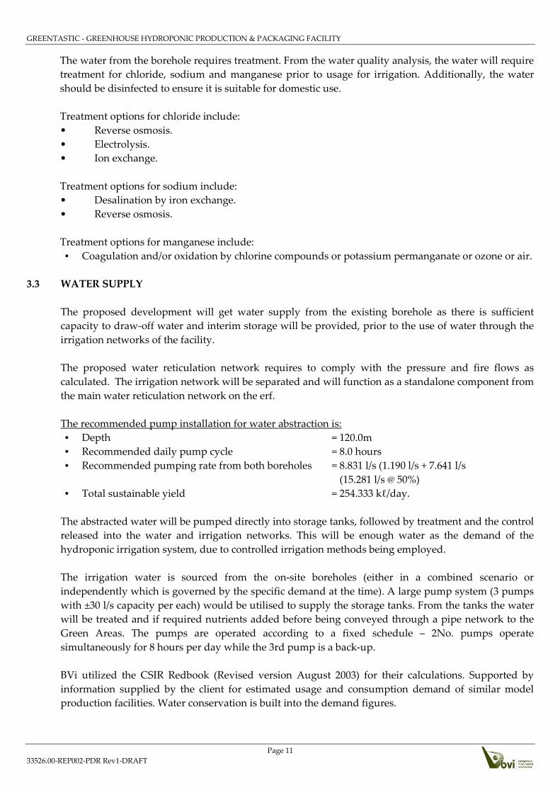
The water from the borehole requires treatment. From the water quality analysis, the water will require
treatment for chloride, sodium and manganese prior to usage for irrigation. Additionally, the water
should be disinfected to ensure it is suitable for domestic use.
Treatment options for chloride include:
• Reverse osmosis.
• Electrolysis.
• Ion exchange.
Treatment options for sodium include:
• Desalination by iron exchange.
• Reverse osmosis.
Treatment options for manganese include:
• Coagulation and/or oxidation by chlorine compounds or potassium permanganate or ozone or air.
3.3 WATER SUPPLY
The proposed development will get water supply from the existing borehole as there is sufficient
capacity to draw-off water and interim storage will be provided, prior to the use of water through the
irrigation networks of the facility.
The proposed water reticulation network requires to comply with the pressure and fire flows as
calculated. The irrigation network will be separated and will function as a standalone component from
the main water reticulation network on the erf.
The recommended pump installation for water abstraction is:
• Depth = 120.0m
• Recommended daily pump cycle = 8.0 hours
• Recommended pumping rate from both boreholes = 8.831 l/s (1.190 l/s + 7.641 l/s
(15.281 l/s @ 50%)
• Total sustainable yield = 254.333 kℓ/day.
The abstracted water will be pumped directly into storage tanks, followed by treatment and the control
released into the water and irrigation networks. This will be enough water as the demand of the
hydroponic irrigation system, due to controlled irrigation methods being employed.
The irrigation water is sourced from the on-site boreholes (either in a combined scenario or
independently which is governed by the specific demand at the time). A large pump system (3 pumps
with ±30 l/s capacity per each) would be utilised to supply the storage tanks. From the tanks the water
will be treated and if required nutrients added before being conveyed through a pipe network to the
Green Areas. The pumps are operated according to a fixed schedule – 2No. pumps operate
simultaneously for 8 hours per day while the 3rd pump is a back-up.
BVi utilized the CSIR Redbook (Revised version August 2003) for their calculations. Supported by
information supplied by the client for estimated usage and consumption demand of similar model
production facilities. Water conservation is built into the demand figures.

GREENTASTIC - GREENHOUSE HYDROPONIC PRODUCTION & PACKAGING FACILITY
Page 12
33526.00-REP002-PDR Rev1-DRAFT
The ultimate project will be developed over various phases, with no timelines and budgets set for the
completion of the project as a whole. The final project is anticipated to comprise of the following elements
once complete:
• 19.400Ha of Greenhouses and hydroponics, comprising of 18 greenhouses at 130m × 40m in size.
• Alternative agricultural activities (chickens, nursery, etc.).
• Cleaning, sorting, packing and cold storing facility.
• Operational buildings (offices, multi-use facility, ablution, management accommodation, storage
buildings).
• Infrastructure (water, electrical, access roads, sewerage treatment, stormwater management).
The following production rates are anticipated, once the facility operates at peak production:
• Strawberries – 1 ton / day – for ± 9 months of the year.
• Tomatoes – 3 tons / day – year round.
• Cucumbers – 2 tons / day – year round.
• Peppers – 1.5 tons / day – year round.
• Lettuce – 5 tons / day – year round.
A master plan that indicates the client’s holistic plan for the project will be prepared once the agricultural
land has been acquired. Environmental authorisation and land use consent requirements for the project
as a whole, therefore all information has been based on the holistic project.
The water demand requirements are estimated as follows:
Table 3-1: Average Daily Water Demand
Development Type
Plant Area
(Ha) Amount of
Units
Daily
Demand per
Unit (ℓ/day)
Daily Demand
(ℓ/day)
Tomatoes 2.0 20 000 m2 4.0 lt/d/m2 80 000
Cucumbers 1.0 10 000 m2 3.5 lt/d/m2 35 000
Peppers 1.0 10 000 m2 3.5 lt/d/m2 35 000
Strawberries 3.0 30 000 m2 3.5 lt/d/m2 105 000
Lettuce 3.0 30 000 m2 3.0 lt/d/m2 90 000
Domestic Demand
(Workers & Personnel)
250 people 85 lt/p/d
21 250
Wash-down Produce Preparation Sum 6 750 lt/day 6 750
Total Daily Water Demand
373 000 ℓ/day
(373.0 m3/day)
or 4.317 l/s
Total average daily demand quantities were calculated by multiplying the different peak factors with
the average daily flow.
Table 3-2: Average Daily Demand with Peak Factors
Associated Peak Factors Peak
Factor
Quantity
(ℓ/s)
Peak Design Flow 2.75 11.872
Summer Peak Design Flow 1.25 14.840

GREENTASTIC - GREENHOUSE HYDROPONIC PRODUCTION & PACKAGING FACILITY
Page 13
33526.00-REP002-PDR Rev1-DRAFT
The average daily flow for the Development will be 11.872 ℓ/s and the Annual Average Daily Demand
is 374.395 kℓ/yr. The calculation is based on the criteria provided by the client during the design
development stage. The calculations yield is based on the client’s consumption estimates and data, which
is relative to similar projects situated on other areas. The rational approach suggests that the Annual
Average Daily demand is direct proposal to the average daily demand, mainly contributed to the
working of the facility and hydroponic system.
The greenhouse irrigation mode is drip irrigation and hydroponics. The water that is used throughout
the irrigation recycle will be re-used in the facility at least twice per annual cycle (Nutrient Solution and
Recovery and Determent System). The volume and frequency of the re-use of the water through the
irrigation system will be determined from measurements of the quality, taken at regular intervals whilst
the facility is operational. The treatment options vary and a conservative approach has been adopted,
whereby the cycle is less than halved. The cycle could be adjusted downward by a greater percentage
based on the treatment required. Limited treatment is usually required since a great deal of the nutrients
and fertilizer is reclaimed once the water exists the facility.
In order to connect the water network of the proposed Development to the existing borehole, additional
infrastructure will be required.
The following additional infrastructure will be required for the supply system includes:
� Pumping equipment to be provided at the borehole inclusive of valves, electrical motors,
electrical control systems, backflow prevention and piping works.
� New storage tanks for the abstracted water, which will then be treated.
� Treatment facility and associated infrastructure and equipment prior to discharge water into the
water networks for the use in the hydroponic system and for domestic consumption areas.
� Additional fire water storage tanks, which does not require treatment of the water quality.
� Interconnecting the back-up borehole to this system, inclusive of all associated equipment and
infrastructure required for the integration into the water supply system.
The calculated storage required for water abstracted from the boreholes are:
• Demand by system = 11.872 ℓ/s
• Storage Required = 1 025 740.800 lt/day x 2 days of storage required
= 2 051 481.600 lt (Say 2 250 m3).
= 2No. tanks of 17.66mØ at 4.6m high (2 253.508 m3)
(Standard Rainbow Reservoirs Pty Ltd. tank, made from Aluzinc® steel,
sectional water storage tanks or similar.)
• Fire Storage = 50% water storage
= 50.0% * 2 250 m3
= 1 125.000 m3
= 1No. tank of 17.66mØ at 4.6m high (1 126.754 m3)
The calculated freshwater demand during operations are:
• At a combined abstraction yield of 11.872 l/s, thus

GREENTASTIC - GREENHOUSE HYDROPONIC PRODUCTION & PACKAGING FACILITY
Page 14
33526.00-REP002-PDR Rev1-DRAFT
~ 42 739.2 l/hr x 10.0 hrs (pumping time) = 427 392.000 lt/Day
~ 427 392.000 lt/Day x 5.5 Days = 2 350 656.0 lt (2 350.656 m3)
x6 Days would be estimated to replenish the total storage volume and directly equal to the time
required to replenish the entire system, should a complete flush of all system be required.
3.4 IRRIGATION DEMAND
The irrigation demand (Green Network – Hydroponic growth areas) that will be required for the Green
houses and the entire hydroponic system has been discussed in the previous section. This irrigation
system which service the hydroponic growth areas, is designed by Tianjin DAYU Irrigation Co. Ltd.
Based in China, refer to Annexure F for the system details.
A secondary irrigation system is required to disperse the excess stormwater run-off and/or water
originating from a flush-event in the hydroponic system. This will also assist with infiltration and
recharge of the ground water. This irrigation system shall be known as the ‘Brown Network’ and will be
discussed in this section of the report.
The 30.0m Building Buffer Zone areas around the perimeter of the erf has been created to function as
Private Open Spaces. These areas will be irrigated with the surplus treated stormwater run-off that
would not be re-used in the hydroponic system. The stormwater run-off will be treated and heavy metals
will be removed. The treated run-off is stored in an open detention pond (wet pond), where evaporation
will assist in dispersing water. The stormwater run-off discharge into a stormwater system or eco system,
is not available on site. No formal downstream stormwater or river course exists. This system was
developed to support vegetative growth on the Erf as well as to protect the downstream properties from
receiving large volumes of concentrated run-off from the Hydroponic Farm.
From the detention pond (D1) the water will be pumped through a network of irrigation pipes and
transported, to irrigate the large Open spaces making up the Building Buffer Zone areas and evaporation
will assist in the dispersing of the access water by implementing high velocity spray irrigation points
(water canon type irrigation practices). Similar to Rotrix Africa which is a low costs and labour traveling
irrigation system).
The irrigation system functions as a closed system with top-up water being supplied from the storage
tanks at the boreholes, if needed in periods of seasonal no or low rainfall. This would be an ad-hoc
arrangement, to support vegetation from dying. The balance of treated effluent and stormwater run-off
on site will be utilised for the irrigation of the Building Buffer Zone. Any water stored from the flush-
event of the media in the hydroponic farm will also be used in this irrigation system. This is referred to
as the liquid backwater and the liquid return treatment option.
The access water which will be generated by the sub-surface stormwater run-off and flushed water
existing the hydroponic system will be stored in a wet detention pond (Dam1). Limited bulk irrigation
will therefore be done by means of Potable Water, only required in summer seasonal periods which
includes December, January, and February, if required.
The area of the ‘Brown Network’ is 14.866 Ha, including the Building Buffer Zones, eco-sensitive areas,
non-go area corridors and access roadways. The areas that could be irrigated is equal to 10.895 Ha which
excludes the No-go Areas and eco-sensitive areas. BVi assumed that for every one square meter (1m²),
20mm of irrigation could be done to dispersers surplus water generated by the facility operations.

GREENTASTIC - GREENHOUSE HYDROPONIC PRODUCTION & PACKAGING FACILITY
Page 15
33526.00-REP002-PDR Rev1-DRAFT
Therefore, the storage required for the irrigation demand will be 2 179.0m³. This volume will be stored
in Detention Dam D1 (refer to Section 6: Stormwater), which will be a wet pond.
The total storage volume of the detention pond consists of two combined basins. Each basin could
function independently for one another.
• Basin No. 01 (Stormwater Run-off storage):
Thus, Estimated footprint area equal to 1 300m2 (25.0m x 52.0m), with a maximum depth equal
to 1.75m with an estimated yield volume of 2 270m3.
NOTE: The calculation of the total stormwater run-off storage is discussed in Section 6 of this report.
• Basin No. 02 (Flush-event storage):
Thus, Estimated footprint area equal to 250m2 (25.0m x 10.0m), with maximum depth equal to
1.5m with an estimated yield volume of 373m3.
The combined detention pond (D1) is required should an event occur where the entire hydroponic
growth media is flushed inclusive of a storm event, for an estimated capacity of ± 2 643m3, excluding the
freeboard height.
The detention pond will be shaped along the Existing Ground Level (EGL) to be formed by a cut-to-fill
scenario and with embankments of maximum 1:3 (V:H) slopes. The detention pond will be fenced with
a 1.8m high security fence, to provide added security against accidental events where people could fall
into the pond. A 3.0m wide access roadway will be constructed along the perimeter of the detention
pond for maintenance access, visual inspections and added security measure.
The balancing of the stored water to irrigation use is as follows: • Thus, combined storage available from Pond (D1) = 2 643.0m3
• Irrigation allowance ‘Brown Network’ (excl. eco-sensitive areas) = 2 179.0m³
• Balance = 464.0m3 (Surplus water)
The flush-event generates 373m3 of water per flush-event. The ‘Brown Network’ covers 10.895Ha
available to use for incremental irrigation practises. The entire ‘Brown Network’ could be divided in
6No. application zones, comprising of 18 650m2 each.

GREENTASTIC - GREENHOUSE HYDROPONIC PRODUCTION & PACKAGING FACILITY
Page 16
33526.00-REP002-PDR Rev1-DRAFT
SECTION 4- BULK SEWERAGE SUPPLY
The proposed development falls within the existing Blaauwberg drainage area. No formal sewer
connection is available that links this erf to the Atlantis sewer network. Therefore, on site treatment of
effluent will be required. The preferred treatment option is the Becon Watertech configuration based on
trickling filter process and deploys the rotating biological contractor (RBC) derivative.
The expected internal daily sewer demands were assumed to be 70% of the calculated water demand for
the workforce and personnel. The total daily sewer demand will therefore be 0.172ℓ/s.
Allowance for 15% infiltration was made to calculate the average wet daily flow, which resulted in
0.197ℓ/s. The peak flow rate was calculated utilizing a peak factor of 2.5. The expected peak flow as
calculated will be 0.494 ℓ/s.
In order to formalise the sewer network of the proposed development, additional infrastructure will be
required.
The following additional infrastructure will be required to drain the sewerage for the Development:
� New 160mm diameter outfall sewer.
� New 200mm diameter outfall sewer.
� New waste water treatment facility or plant.
The proposed development will collect and convey sewer throughout the development footprint via
gravity network and discharge into the Waste Water Treatment Facility. The treatment facility shall be
located on the lower south eastern corner of the Erf. The size of the internal sewer main will range from
160mm diameter to 200 mm diameter Class 34 uPVC pipes to accommodate the peak flow rate of 0.494
l/s.
See Annexure C for the Bulk Sewer Layout for proposal of bulk sewerage.
The proposed sewer treatment option includes:
• A Primary Phase Separation through septic tanks,
• secondary settling tank (humus tank) and
• Tinkle filtering.
RBC plant are not affected by overloading of the sewer system. No daily de-sludging is required, sludge
is continuously returned to the septic tank and normally would require de-sludging once every 12-
months. Separate sealed septic tanks assist the system to eliminate any smell and odour. The capacity of
the septic tank is designed in accordance with recommendations imposed by the South African Institute
of Water Pollution Control. The treated effluent will be discharged into the upper compartments of the
stormwater retention pond for final polishing and settlement. The treated effluent would comply to the
Special Limit of water quality under SANS 241-1:2015.
The proposed plant to be used on this project is the (Be-Pac 30 C) capable of handling and treating 30
kL/Day or a population equivalent to 250 p/day, assuming an 18-hour working day. The plant is
conservative and make allowances for season workers that could contribute to increased flow rates at

GREENTASTIC - GREENHOUSE HYDROPONIC PRODUCTION & PACKAGING FACILITY
Page 17
33526.00-REP002-PDR Rev1-DRAFT
certain times. The plant is sized adequately to sustain the sewer flow form the day-to-day operations of
the facility.
The discharge quality of the treated effluent will comply to the following:
*After removal of algae Source: Table 2.1 South African Government Gazette No. 36820, 6 Sept. 2013
WASTEWATER LIMIT VALUES APPLICABLE TO DISCHARGE OF WASTEWATER INTO A WATER RESOURCE
SUBSTANCE / PARAMETER GENERAL LIMIT SPECIAL LIMIT
Faecal Coliforms (per 100ml) 1000 0
COD - Chemical Oxygen Demand (mg/l) 75* 30*
PH 5,5 - 9,5 5,5 - 7,5
Ammonia (ionised and un-ionised) as Nitrogen
(mg/l)
3 2
Nitrate / Nitrite as Nitrogen (mg/l) 15 1,5
Chlorine as Free Chlorine (mg/l) 0,25 0
Suspended Solids (mg/l) 25 10
Electrical Conductivity (mS/m) 70ms/m above intake to a
maximum of 150 mS/m
50mS/m above background
receiving water, to a maximum of
100 mS/m
Ortho-Phosphate as phosphorous (mg/l) 10 1 (median) and 2,5 (maximum)
Fluoride (mg/l) 1 1
Soap, oil or grease (mg/l) 2,5 0
Dissolved Arsenic (mg/l) 0,02 0,01
Dissolved Cadmium (mg/l) 0,005 0,001
Dissolved Chromium (mg/l) 0,05 0,02
Dissolved Copper (mg/l) 0,01 0,002
Dissolved Cyanide (mg/l) 0,02 0,01
Dissolved Iron (mg/l) 0,3 0,3
Dissolved Lead (mg/l) 0,01 0,006
Dissolved Manganese (mg/l) 0,1 0,1
Mercury and its compounds (mg/l) 0,005 0,001
Dissolved Selenium (mg/l) 0,02 0,02
Dissolved Zinc (mg/l) 0,1 0,04
Boron (mg/l) 1 0,5
Figure 6: Sewer discharge quality after on-site treatment

GREENTASTIC - GREENHOUSE HYDROPONIC PRODUCTION & PACKAGING FACILITY
Page 18
33526.00-REP002-PDR Rev1-DRAFT
SECTION 5- ROADS NETWORK
The HOH Multi-Crop Greenhouse Hydroponic fresh produce, production and packaging facility
proposed on Portion 39 of Farm Klein Dassenberg No. 20. will gain formal access from the
Municipal/Provincial road network. The main access will be taken from Klein Dassenberg Road to the
west of the N7 and east of R304.
5.1 ROADWAYS CLASSIFICATION
The class of the different roads are as follows:
� Klein Dassenberg Road is a class 3 road.
The additional slip lanes, turning lanes, deceleration and acceleration lanes to be added to formalise
the access to the erf will comply to Class 3 requirements. Typically 3.7m wide lanes 40mm/50mm
thick asphalt surface, kerbed either side and sidewalks provided. Street lighting will be provided
for illumination during foul weather conditions or night time.
Figure 7: Typical details for access roadways taken from Provincial & Municipal roads
� The right-of-way servitude across the neighbouring property will be a Class 4 Road.
Typically 3.7m wide with 80mm thick concrete block paved surfacing, kerbed either side with formal
stormwater drainage. Sidewalks and street lights shall be provided for this entrance roadways to
the facility.

GREENTASTIC - GREENHOUSE HYDROPONIC PRODUCTION & PACKAGING FACILITY
Page 19
33526.00-REP002-PDR Rev1-DRAFT
Figure 8: Typical Illustration of access roadway surfacing
� The internal parking area at the administrative office will be a Class 5 Road.
The parking area will be structured around the northern side of the administrative building complex
and will have 80mm interlocking paving, edge restrains, walkways and formal stormwater
drainage. Stormwater drainage could include permeable paving on the parking areas. The areas will
be shaped to facilitate stormwater run-off.
Figure 9: Typical illustration of details for parking areas
� The warehouse delivery/collection hardstand area will be a Class 4 Road.
The hardstand at the delivery, collection and package areas will be in-situ concrete surface beds with
edge restrains and formal stormwater drainage. The areas will be shaped to facilitate stormwater
run-off.
Figure 10: Typical hardstand surfaces at packhouse areas
� The main access collector backbone roadway through the erf will be Class 5 Roads.
This road will be used more frequently since it will be the main link between the packhouse and
sorting areas and the individual green house structures. The roadway will be formalised with
stormwater drainage and will have a hard-wearing surface consisting of a twee spoor 3-Block track.

GREENTASTIC - GREENHOUSE HYDROPONIC PRODUCTION & PACKAGING FACILITY
Page 20
33526.00-REP002-PDR Rev1-DRAFT
Figure 11: Typical access collector roadway construction detail
� The interlinking access roadways between the green house structures will be Class 5 Roads.
The internal access roadways will be constructed with a G5 wearing course to improve durability
and supress dust on the roadway during frequent use. The roadway will be shaped with a 2.5%
crossfall to facilitate stormwater drainage. Side channels will be provided to assist in stormwater
management.
Figure 12: Typical details for access roadways along Greenhouse structures
5.2 DESIGN VEHICLES
The standard design vehicles utilised to verify design geometry on roadways are based on the Green
Book (AASTHO) Policy on Geometric Design of Highways and Streets and inter alia include the
following aspects.

GREENTASTIC - GREENHOUSE HYDROPONIC PRODUCTION & PACKAGING FACILITY
Page 21
33526.00-REP002-PDR Rev1-DRAFT
Figure 13: AASTHO Standard Turning Characteristics
Figure 14: AASTHO Exhibit 2-1 for Standard design vehicles
For the design on the roadways in this development the following vehicles was considered
• Quadbike and trailer – No formal designation awarded.
• Passenger car – P
• Single unit truck – SU
GREENTASTIC - GREENHOUSE HYDROPONIC PRODUCTION & PACKAGING FACILITY
Page 22
33526.00-REP002-PDR Rev1-DRAFT
• Farm tractor - TR
• Delivery trucks – WB-40
The choice of the design vehicle has been influenced by the following factors:
• The functional classification of a roadway, and by the proportions of the various types and sizes of
vehicles expected to use the facility.
• On rural facilities, to accommodate truck traffic, one of the semitrailer combinations trucks has
been considered in the design.
5.3 ACCESS CONTROL
Access to the Erf is taken from a Provincial Road and the WCPG Access Management Guidelines,
Version 2020 was utilised to evaluate access spacing as well as sight distance for egress and ingress to
the erf.
The sight distances were found to be compliant and conforms to the requirements from WCPG.
Access to the erf was evaluated and found acceptable based on the design criteria.

GREENTASTIC - GREENHOUSE HYDROPONIC PRODUCTION & PACKAGING FACILITY
Page 23
33526.00-REP002-PDR Rev1-DRAFT
SECTION 6- STORMWATER
6.1 TOPOGRAPHY
The site has a relatively flat natural topography with a fall of approximately 14m in a south easterly
direction. Natural ground levels range from 118 metres above mean sea level in the north-western corner
of the site to approximately 114m in the south-eastern corner of the site.
In the design of the stormwater system, rainfall data from the “City of Cape Town Rainfall Design Grid,
August 2013 at Lat. 33deg 36’ and Long. 18deg 32’ will be used. According to this weather station, the
mean annual precipitation (MAP) is 453mm. The given altitude for this area on the grid is accurate at
116m metres above mean sea level, the average for the levels stated above.
All pre-development stormwater runoff flow generally occurs in the south-eastern direction via a
non-perennial tributary approximately 2.7km south east of the site. Runoff from the upstream upper two
thirds of the site is intercepted directly by a drainage line on site.
6.2 STORMWATER MANAGEMENT PLAN
Stormwater runoff from the development area should be managed so that no damage to the environment
is caused during storms with a probability frequency of 1:10 years or more. Only minor, repairable
damage without significant loss or risk to life and property will occur during storms with a probability
frequency of 1:50 years and more. Note that a “storm frequency” equates to a “probability of occurrence”
of a storm event that should be used to assess the annual budget provision for remedial works, should
the event occur.
Figure 15: Typical stormwater management around greenhouse structures
GREENTASTIC - GREENHOUSE HYDROPONIC PRODUCTION & PACKAGING FACILITY
Page 24
33526.00-REP002-PDR Rev1-DRAFT
No formal stormwater drainage system nor treatment systems are available on the property. The
greenhouses will generate stormwater runoff equivalent to a 10.8ha impervious area and therefore
stormwater management will be required to prevent erosion and localised flooding. The areas between
the greenhouses will be used as an infiltration area for stormwater from small downpours. Surface
drainage, channels, overland escapes and underground pipes will be formalised to convey stormwater
to a stormwater retention pond, to cater for runoff during intense downpours.
The Stormwater Management Plan for the development will have the following objectives:
� To protect all life and property from damage by stormwater and floods;
� To prevent erosion of soil by water;
� To improve the quality of stormwater run-off for re-use;
� To protect and enhance water resources in the catchments from pollution and siltation;
� To protect and enhance the local and downstream water courses and their eco-systems.
The Stormwater Management Plan encourages the following:
� Maintain adequate ground cover at all places and at all times to negate the erosive forces of
stormwater;
� Prevent concentration of stormwater flows at any point where the ground is susceptible to
erosion;
� Reduce stormwater flows as much as possible by the effective use of attenuating engineered
devices;
� Ensure that all stormwater control works are constructed in a safe and aesthetic manner in
keeping with the overall development theme for the area;
� Prevent pollution of water ways and water features by litter, silt and suspended solids and to
reduce dissolved solids in stormwater discharges;
� Contain soil erosion, whether induced by wind, water forces or by construction activities through
protective works to trap sediment at appropriate locations in the development. This applies
particularly during construction.
6.3 STORMWATER RISKS
Because of the very loose soil conditions across the whole site, the top soil is considered generally
erodible. It is suggested that a heavy vibratory roller be used to compact the loose sand after site
clearance.
The new development will tend to reduce the natural rainfall infiltration and increase storm runoff.
Downstream flood damage risks will therefore increase unless adequate attenuation of flood runoff is
provided. The design of the major stormwater system will address this issue as far as possible, but it is
important to note that each individual area and its associated infrastructure will be designed such that
the downstream post-development flood risks are no greater than that of the pre-development flood
risks.
6.3.1 MAJOR SYSTEM
The major stormwater system consists of the detention dams, open channels, roadways and other hard
impermeable surfaces. It also includes other devices such as wetlands that are constructed to manage
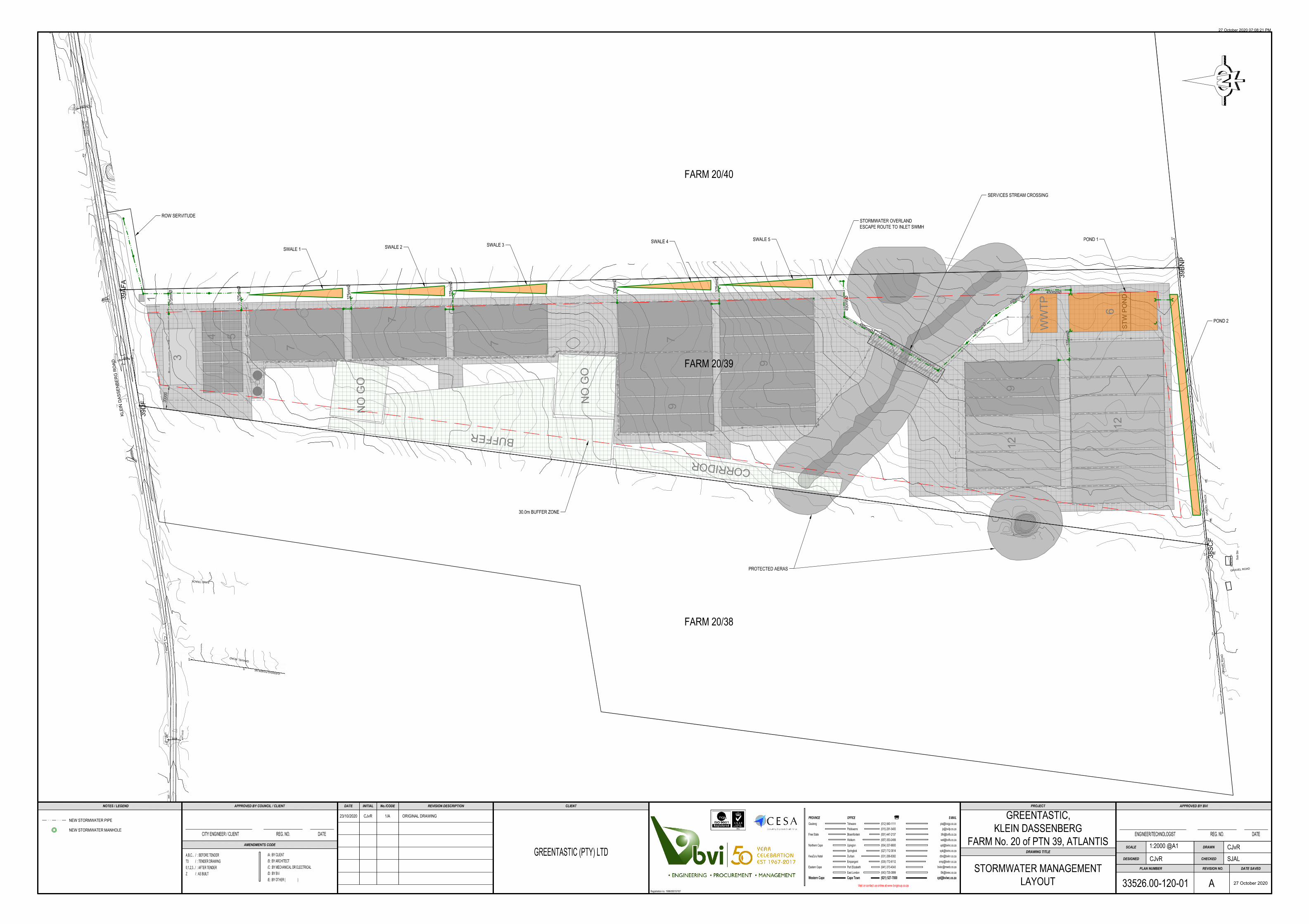
stormwater. Refer to Annexure B for a layout of the planned major stormwater system.

GREENTASTIC - GREENHOUSE HYDROPONIC PRODUCTION & PACKAGING FACILITY
Page 25
33526.00-REP002-PDR Rev1-DRAFT
The land use and associated runoff coefficients for pre- and post-development conditions for four
sub-catchments are shown in Table 6-1 below. Refer to Annexure C – Sub-catchment Layout for visual
representation of these sub-catchments. The Land Use area designated as “green” represents the natural
state of the site and its run-off factor is derived from the sum of the following components:
� Surface slope: Flat areas ⇒ Cs = 6
� Permeability: Permeable ⇒ Cp = 6
� Vegetation: Grasslands ⇒ Cv = 17
The run-off factor of 29 is then rounded up and taken as 30 for the whole site pre-development, as well
as post-development for the remaining “green” areas.
Land Use Area (Ha)
Pre-Development
Runoff Coefficient (%)
Post-Development
Runoff Coefficient (%)
A Cpre Cpost
Sub-Catchments C1 to C4
Structures (heavy industry) 10.8 30 90
Green 19.8 30 30
Non-Perennial and off-set* 3.7 30 100
Total Catchment (Weighted Average
Run-off Factor) 30.6 30 52
* This Land Use area is a no-go zone that will not be affected post-development and will not contribute to stormwater
runoff to be managed. Stormwater from this area is assumed to follow the natural drainage line.
Table 6-1: Land use Allocation and Run-off coefficients
The rainfall intensity for the design storm is derived from the Intensity Duration Frequency Curves for
the site area where the Mean Annual Precipitation (MAP) is 453mm. The calculated rainfall intensities
for each return period for the undeveloped site area and for the proposed development were calculated
and are illustrated in the below table. Note that all post-development time of concentrations for the
various catchments were calculated as less than fifteen minutes. The minimum time of concentration of
fifteen minutes were thus used in each case, as prescribed by the SANRAL Drainage Manual, to get the
corresponding rainfall intensities.
RETURN
INTERVAL 1:2 1:5 1:10 1:20 1:50 1:100
CATCHMENTS PRE POST PRE POST PRE POST PRE POST PRE POST PRE POST
C1 24.0 36.3 32.0 48.8 38.0 58.0 44.0 67.2 53.0 80.5 60.0 91.5
C2 18.0 36.3 24.5 48.8 29.0 58.0 33.0 67.2 40.0 80.5 45.5 91.5
C3 20.0 36.3 27.0 48.8 32.0 58.0 37.0 67.2 44.0 80.5 50.0 91.5
C4 17.5 36.3 23.0 48.8 27.5 58.0 32.5 67.2 38.0 80.5 43.0 91.5
Table 6-2: Rainfall Intensities (mm/h)
The calculated intensities were used to determine the catchment pre and post development flow rates to
determine the storage capacity required per catchment. The rational method calculated flows from the
catchments are illustrated in the table below. Pre and post development 1:2, 1:5, 1:10, 1:20, 1:50 and 1:100
year return period storm events were calculated.

GREENTASTIC - GREENHOUSE HYDROPONIC PRODUCTION & PACKAGING FACILITY
Page 26
33526.00-REP002-PDR Rev1-DRAFT
RETURN
INTERVAL 1:2 1:5 1:10 1:20 1:50 1:100
CATCHMENTS PRE POST PRE POST PRE POST PRE POST PRE POST PRE POST
C1 0.049 0.130 0.066 0.174 0.078 0.207 0.091 0.240 0.109 0.287 0.124 0.326
C2 0.147 0.514 0.200 0.691 0.379 0.821 0.270 0.951 0.327 1.140 0.372 1.295
C3 0.121 0.380 0.163 0.511 0.266 0.607 0.224 0.704 0.266 0.843 0.302 0.958
C4 0.162 0.581 0.212 0.781 0.434 0.928 0.300 1.075 0.351 1.288 0.397 1.464
Table 6-3: Stormwater Flows (m3/s)
From the calculated flows the storage capacity for each sub-catchment was determined for the 1:50 year
storm event. The pre-development flow was used as the permissible discharge form the catchments.
The calculated storage capacity is illustrated in the below table.
CATCHMENTS
CATCHMENT FLOW
(m³/s) FLOW TO
STORAGE (m³/s)
CALCULATED
STORAGE
(m³) PRE POST
C1 0.109 0.287 0.178 160
C2 0.327 1.140 0.813 732
C3 0.266 0.843 0.577 519
C4 0.351 1.288 0.937 844
Total 1.052 3.558 2.506 2255
Table 6-4: Detention Storage for 1:50 Year Return Interval
The stormwater discharged from the respective sub-catchment will be accommodated in the major
stormwater system where capacity will be allowed for to convey the runoff from a 1:50 year storm event.
The main stormwater system will be water collected from the greenhouses and surrounding areas
(sub-catchments 1, 2 and 3) that will be transported by underground pipes to the eastern side of the
property. Here it will be discharged in a series of five earth swales sloping to the south. Any stormwater
over flowing down to the final swale, situated above the natural drainage line on site, will be conveyed
to the stormwater retention pond south of the site. Stormwater from the greenhouses situated in
sub-catchment 4 will flow directly into the retention pond. Stormwater will be treated in the retention
pond where after it can be pumped back in the irrigation system.
Individual Sub-Catchments within the development will be served by underground pipe networks as
well as open channels flowing to the abovementioned swales that will follow the natural fall to the south.
The first three swales will accommodate runoff from sub-catchments 1 and 2 that will have total storage
of approximately 900m3 plus freeboard. The remaining two swales will accommodate runoff from
sub-catchment 3 that will have an approximate storage capacity of 520m3 plus freeboard. The stormwater
retention pond will thus cater for the overflow from above swales plus the 850m3 runoff from
sub-catchment 4. An additional pond alongside the southern border will be used for emergency
overflows.
6.3.2 MINOR SYSTEM
The minor stormwater system consists of any measures provided to accommodate stormwater runoff
within “green” areas and convey the runoff to the major stormwater system i.e. road stormwater,
catchpits, channels and collector pipes.

GREENTASTIC - GREENHOUSE HYDROPONIC PRODUCTION & PACKAGING FACILITY
Page 27
33526.00-REP002-PDR Rev1-DRAFT
6.3.3 SUSTAINABLE URBAN DRAINAGE SYSTEM
The following principles were followed by the planning team:
� Design for the site in general must avoid concentration of stormwater runoff both spatially and
in time and to provide for on-site attenuation of stormwater runoff to limit peak flows to pre-
development levels.
� Improve quality of runoff from the development areas to pre-development concentrates.
� Where possible natural infiltration to take precedence over pipe reticulation.
� Infiltration swales and wetlands to be used as stormwater cleaning devices.
� Development guidelines will be compiled whereby individual developments will be encouraged
to manage stormwater on site so as to reduce the impact on downstream systems.
Sedimentation and screen structures will be for sedimentation of suspended material within stormwater
flows and screens will provide trash trap areas for any solid waste finding its way within the stormwater
system. The swales are designed to infiltrate naturally with sub-surface drainage connecting to them.
These infiltration areas reduce any pollutants in the stormwater run-off.
Figure 16: Typical stormwater drainage along gravel surfaced access roadways
Figure 17: Typical swale construction and details for the Buffer Zones around perimeter of Development

GREENTASTIC - GREENHOUSE HYDROPONIC PRODUCTION & PACKAGING FACILITY
Page 28
33526.00-REP002-PDR Rev1-DRAFT
Figure 18: Swale with check dams along the Buffer Zone to facilitate retention and infiltration

GREENTASTIC - GREENHOUSE HYDROPONIC PRODUCTION & PACKAGING FACILITY
Page 29
33526.00-REP002-PDR Rev1-DRAFT
SECTION 7- ELECTRICAL NETWORK
7.1 INTRODUCTION
The proposed development is situated within Eskom’s supply area, in close proximity to Dassenberg
Farmers 2 (11kV network). The figure below indicates the position and extent of the Eskom
infrastructure.
7.2 EXISTING SUPPLY AND CAPACITY
Initial communication with Eskom (Mr. Alistair-Lee Potgieter, Network Planning, Eskom Distribution –
Western Cape Operating Unit) yielded that this network is currently moderately constraint and any
significant load increases on this network would require major strengthening. This will entail to upgrade
of backbone conductors and possibly re-building of the overhead line to support bigger size conductors,
installation of a voltage regulator, etc. All of these elements are in addition to the bulk infrastructure for
the connection.
Eskom did report however, with minor network configuration changes, it is possible to shift this part of
the network to Dassenberg Farmers 1 (11kV) with no additional strengthening required. The developer
would still be responsible for the bulk connection infrastructure and related costs. Typically, a Recloser
for loads of this magnitude and one connection granted.
The estimated ADMD for this development based on the current design is calculated to be 1800kVA. The
proposed development is situated within Eskom’s area of supply. The development is located in close
proximity to the existing Dassenberg Farmers 2 Feeder (11kV overhead network). Eskom’s Dassenberg
Farmers 2 Feeder is located to the northern side of the proposed development.
This network is currently moderately constraint. Any significant load increases on this network would
require major network strengthening. Strengthening could entail:
• upgrading of backbone conductors,
• possibly re-building of the overhead line to support bigger size conductor,
• installation of a voltage regulator, etc.
The above network strengthening would be in addition to the bulk electrical infrastructure required for
this development.
However, with minor network configuration changes, it is possible to shift this part of the network to
Dassenberg Farmers 1 Feeder (11kV overhead network) with no additional strengthening required. For
loads of this magnitude, the developer would still be responsible for the bulk connection infrastructure
which would typically entail the installation of a recloser and a bulk MV metering point.
With the above de-loading of the feeders and associated modifications to the network, bulk electricity
supply could be made available to supply this development. It must however be noted that capacity
cannot be reserved until a formal application is submitted and the resulting bulk contribution fees paid
by the developer.

GREENTASTIC - GREENHOUSE HYDROPONIC PRODUCTION & PACKAGING FACILITY
Page 30
33526.00-REP002-PDR Rev1-DRAFT
An application has been submitted to support the Eskom investigation into the possible network’s
changes and/or supply to the Erf.
Contribution costs will be applicable to the development of this erf and these costs will be finalised and
provided by Eskom once the supply network analysis has been done internally by Eskom.
The capacity could only be reserved, once the acceptance of a Budget Quote issued by Eskom has been
established.

GREENTASTIC - GREENHOUSE HYDROPONIC PRODUCTION & PACKAGING FACILITY
Page 31
33526.00-REP002-PDR Rev1-DRAFT
SECTION 8- CONCLUSION
The contents of this report indicate the methodology followed for the design and implementation of the
Commercial Controlled Environment Portion 39 of Farm Klein Dassenberg No. 20. development near
Atlantis.
The Demand and Capacity Analysis and calculations performed by BVi Consulting Engineering indicate
that the existing borehole water supply on the erf would be sufficient for the intended development and
the use of the water. The development is situated on the fringe of the municipal sewer networks and a
connection to this system would be costly. The option to treat on-site sewerage and re-sue the effluent
would be the preferred option. Treatment of the effluent will be done to meet the requirements and
standards of the DWS (Department water and Sanitation) special criteria.
An entrance from the Klein Dassenberg Road (Provincial proclaimed Road and maintained by the
Municipality) through the right of way servitude roadway which will be registered along the boundary
of the larger farm portion 39/20 and 40/20.
The stormwater management plan is setup to make provision for all environmental issues that may arise
and to protect and enhance downstream water courses and their eco systems.
The electrical demand for the project is limited and solar supported infrastructure is preferred. The
Eskom electrical supply is required to support the facility’s administrative buildings, warehouse and
packing buildings, water, irrigation and sewer pumping equipment and associated infrastructure. The
greenhouse units will be operated and will function from solar based PV panels and associated
infrastructure.
33526.00 (GreenTastic HAOP Atlantis)\33526.00-REP002-PDR Rev1-DRAFT.docx

GREENTASTIC - GREENHOUSE HYDROPONIC PRODUCTION & PACKAGING FACILITY
Page 32
33526.00-REP002-PDR Rev1-DRAFT
ANNEXURE A:
GENERAL SERVICES LAYOUT

39
AF
A
39
DF
39
BN
P
38
SC
F
E
D
G
E
O
F
T
A
R
E
D
G
E
O
F
T
A
R
GR
AV
EL R
OA
D
GR
AV
EL T
RA
CK
CO
NC
RE
TE
GR
AV
EL R
OA
D
TR
UC
K W
AS
HE
R
G
R
A
V
E
L
R
O
A
D
SA
ND
TR
AC
K
K
E
R
B
T
A
R
R
E
D
D
R
IV
E
W
A
Y
B
R
IC
K
P
A
V
IN
G
K
L
E
IN
D
A
S
S
E
N
B
E
R
G
R
O
A
D
30000
1
0
5
.
0
0
1
0
5
.
0
0
1
0
6
.
0
0
1
0
6
.
0
0
1
0
7
.
0
0
1
0
7
.0
0
108.00
1
0
9
.
0
0
1
0
9
.
0
0
1
1
0
.
0
0
1
1
0
.0
0
1
1
1
.0
0
1
1
1
.0
0
1
1
2
.0
0
1
1
2
.0
0
1
1
3
.
0
0
1
1
4
.0
0
1
1
4
.0
0
1
1
5
.
0
0
1
1
6
.
0
0
1
1
6
.
0
0
117.00
1
0
4
.2
5
1
0
4
.
5
0
1
0
4
.
5
0
104.75
104.75
1
0
5
.
2
5
1
0
5
.
5
0
1
0
5
.
7
5
1
0
6
.
2
5
1
0
6
.
2
5
1
0
6
.5
0
1
0
6
.5
0
1
0
6
.7
5
1
0
6
.7
5
1
0
7
.
2
5
1
0
7
.2
5
1
0
7
.
5
0
1
0
7
.
5
0
1
0
7
.
7
5
107.75
1
0
8
.
2
5
1
0
8
.
5
0
1
0
8
.
5
0
1
0
8
.
7
51
0
8
.
7
5
1
0
9
.2
5
1
0
9
.
2
5
1
0
9
.5
0
1
0
9
.5
0
1
0
9
.
7
5
1
0
9
.7
5
1
1
0
.
2
5
1
1
0
.
2
5
110.5
0
1
1
0
.5
0
1
1
0
.
5
0
1
1
0
.
7
5
1
1
1
.
2
5
1
1
1
.
2
5
1
1
1
.
5
0
1
1
1
.
7
51
1
2
.
2
5
1
1
2
.
2
5
1
1
2
.5
0
1
1
2
.
5
0
1
1
2
.7
5
113.25
1
1
3
.5
0
1
1
3
.5
0
1
1
3
.7
5
1
1
4
.2
5
1
1
4
.2
5
114.50
114.50
1
1
4
.
7
5
114.75
115.25
1
1
5
.
2
5
1
1
5
.5
0
1
1
5
.
5
0
1
1
5
.7
5
1
1
5
.7
5
1
1
6
.
2
5
1
1
6
.
2
5
1
1
6
.
5
0
1
1
6
.
5
0
1
1
6
.7
5
1
1
6
.7
5
1
1
7
.
2
5
117.50
1
0
9
.
0
0
1
0
9
.
0
0
109.00
1
1
0
.
0
0
1
1
1
.0
0
1
1
2
.0
0
1
1
3
.
0
0
1
1
4
.
0
0
1
1
5
.
0
0
1
1
6
.
0
0
1
1
7
.
0
0
1
1
7
.0
0
117.00
1
1
8
.
0
0
1
0
8
.
7
5
1
0
8
.
7
5
1
0
8
.
7
5
1
0
8
.7
5
1
0
8
.
7
5
108.75
1
0
8
.
7
5
1
0
8
.7
5
1
0
9
.
2
5
1
0
9
.
2
5
1
0
9
.
2
5
1
0
9
.
2
5
1
0
9
.2
5
1
0
9
.
5
0
1
0
9
.
5
0
1
0
9
.
5
0
1
0
9
.
7
5
1
1
0
.
2
5
1
1
0
.
5
0
1
1
0
.
7
5
111.25
1
1
1
.
5
0
1
1
1
.
7
51
1
2
.
2
5
1
1
2
.5
0
1
1
2
.7
5
1
1
3
.
2
5
113.50
1
1
3
.7
5
1
1
4
.
2
5
1
1
4
.
5
0
1
1
4
.
7
5
1
1
5
.
2
5
1
1
5
.
5
0
1
1
5
.
7
5
116.25
116.50
1
1
6
.
7
5
1
1
6
.7
5
1
1
6
.7
5
1
1
7
.
2
5
1
1
7
.
5
0
1
1
7
.
7
5
3
4 5
NO
G
O
NO
G
O
BU
FF
ER
C
O
R
R
ID
O
R
9
12
12
7
6
WW
TP
9
9
7
7
7
1
CHECKED
REVISION DESCRIPTION
REG. NO.
SCALE
0,1,2,3.../ : AFTER TENDER
/D : BY BVi
/B : BY ARCHITECT
/E : BY OTHER ( )
AMENDMENTS CODE
OFFICE
(043) 735-3899
KwaZulu Natal (031) 266-8382
Western Cape (021) 527-7000
(027) 712-3614
DATEENGINEER/TECHNOLOGIST
Port ElizabethEastern Cape
A,B,C... / : BEFORE TENDER
T0 / : TENDER DRAWING
DATE SAVED
REG. NO.
APPROVED BY BVi
PLAN NUMBER
DRAWN
/A : BY CLIENT
REVISION NO.
CLIENT
DRAWING TITLE
DESIGNED
Polokwane
Bloemfontein
Welkom
Upington
Springbok
(041) 373-4343
[email protected](035) 772-6112Empangeni
PROJECT
CITY ENGINEER / CLIENT DATE
APPROVED BY COUNCIL / CLIENT DATE No./CODEINITIAL
Durban
East London
Cape Town
PROVINCE
Visit or contact us online at www.bvigroup.co.za
/C : BY MECHANICAL OR ELECTRICAL
(057) 353-2499
(051) 447-2137
(054) 337-6600
(015) 291-5400
Free State
Northern Cape
Z / : AS BUILT
NOTES / LEGEND
[email protected] (012) 940-1111Gauteng
GREENTASTIC (PTY) LTD
O:\PROJECTS DRAWINGS\33000 - 33999\33526.00\CIVIL\DESIGN DRAWINGS\33526.00-101-01 REVA_GENERAL SERVICES LAYOUT.DWG
33
52
6.0
0-1
01
-0
1 R
EV
A_
GE
NE
RA
L S
ER
VIC
ES
L
AY
OU
T.D
WG
27 October 2020
27 October 2020 06:54:34 PM
33526.00-101-01 A
1:2000 @A1
CJvR
CJvR
SJAL
GREENTASTIC,
KLEIN DASSENBERG
FARM No. 20 of PTN 39, ATLANTIS
GENERAL SERVICES LAYOUT
23/10/2020 CJvR 1/A ORIGINAL DRAWING
Registration no. 1998/000157/07
NEW STORMWATER PIPE
NEW STORMWATER MANHOLE
NEW FOUL SEWER PIPE
NEW FOUL SEWER MANHOLE
NEW WATER PIPE
NEW IRRIGATION WATER PIPE
NEW IRRIGATION RETURN FEED
PROTECTED AERAS
FARM 20/38
FARM 20/40
FARM 20/39
SWALE 1
SWALE 2
SWALE 3
SWALE 4
SWALE 5
STORMWATER OVERLAND
ESCAPE ROUTE TO INLET SWMH
POND 1
POND 2
30.0m BUFFER ZONE
SERVICES STREAM CROSSING
ROW SERVITUDE
BOREHOLE SUPPLY
(Ex. EHPBH2)

GREENTASTIC - GREENHOUSE HYDROPONIC PRODUCTION & PACKAGING FACILITY
Page 33
33526.00-REP002-PDR Rev1-DRAFT
ANNEXURE B:
STORMWATER MANAGEMENT LAYOUT
slid
in
g
g
a
te
39
AF
A
39
DF
39
BN
P
38
SC
F
E
D
G
E
O
F
T
A
R
E
D
G
E
O
F
T
A
R
IP
=114.65
IP
=114.63
4
5
0
Φ
4
5
0
Φ
450Φ
IP
=119.70
IP
=119.62
IP
=117.42
IP
=117.38
CM
CM
CM
EP
EP
EP
EP
EP
EP
EP
OV
ER
HE
AD
P
OW
ER
LIN
E
EP
GR
AV
EL R
OA
D
GR
AV
EL T
RA
CK
CO
NC
RE
TE
GR
AV
EL R
OA
D
TR
UC
K W
AS
HE
R
TE
L
TE
L
TE
L
Su
b S
tn
G
R
A
V
E
L
R
O
A
D
SA
ND
TR
AC
K
K
E
R
B
T
A
R
R
E
D
D
R
IV
E
W
A
Y
B
R
IC
K
P
A
V
IN
G
K
L
E
IN
D
A
S
S
E
N
B
E
R
G
R
O
A
D
EP
EP
O
V
E
R
H
E
A
D
P
O
W
E
R
LIN
E
1
0
4
1
0
5
1
0
6
1
0
7
1
0
8
1
0
9
1
1
0
1
0
8
1
0
9
1
1
8
117
1
1
6
1
1
5
1
1
4
1
1
3
112
111 1
10
1
1
7
1
1
6
1
1
5
1
1
9
119
1
2
0
1
2
1
119
120
1
1
9
109
1
0
8
107
1
0
6
1
0
6
1
0
7
1
0
8
30000
ST
W P
ON
D
1
0
8
1
0
7
4
5
0
m
m
Ø
4
5
0
m
m
Ø
450mmØ
4
5
0
m
m
Ø
450mmØ
375mmØ
375mmØ
375mmØ
375mmØ
375mmØ
375mmØ
375mmØ
3
4 5
NO
G
O
NO
G
O
BU
FF
ER
C
O
R
R
ID
O
R
9
12
12
7
6
WW
TP
9
9
7
7
7
1
CHECKED
REVISION DESCRIPTION
REG. NO.
SCALE
0,1,2,3.../ : AFTER TENDER
/D : BY BVi
/B : BY ARCHITECT
/E : BY OTHER ( )
AMENDMENTS CODE
OFFICE
(043) 735-3899
KwaZulu Natal (031) 266-8382
Western Cape (021) 527-7000
(027) 712-3614
DATEENGINEER/TECHNOLOGIST
Port ElizabethEastern Cape
A,B,C... / : BEFORE TENDER
T0 / : TENDER DRAWING
DATE SAVED
REG. NO.
APPROVED BY BVi
PLAN NUMBER
DRAWN
/A : BY CLIENT
REVISION NO.
CLIENT
DRAWING TITLE
DESIGNED
Polokwane
Bloemfontein
Welkom
Upington
Springbok
(041) 373-4343
[email protected](035) 772-6112Empangeni
PROJECT
CITY ENGINEER / CLIENT DATE
APPROVED BY COUNCIL / CLIENT DATE No./CODEINITIAL
Durban
East London
Cape Town
PROVINCE
Visit or contact us online at www.bvigroup.co.za
/C : BY MECHANICAL OR ELECTRICAL
(057) 353-2499
(051) 447-2137
(054) 337-6600
(015) 291-5400
Free State
Northern Cape
Z / : AS BUILT
NOTES / LEGEND
[email protected] (012) 940-1111Gauteng
GREENTASTIC (PTY) LTD
O:\PROJECTS DRAWINGS\33000 - 33999\33526.00\CIVIL\DESIGN DRAWINGS\33526.00-120-01 REVA_STORMWATER MANAGEMENT LAYOUT.DWG
33
52
6.0
0-1
20
-0
1 R
EV
A_
ST
OR
MW
AT
ER
M
AN
AG
EM
EN
T L
AY
OU
T.D
WG
27 October 2020
27 October 2020 07:08:21 PM
33526.00-120-01 A
1:2000 @A1
CJvR
CJvR
SJAL
GREENTASTIC,
KLEIN DASSENBERG
FARM No. 20 of PTN 39, ATLANTIS
STORMWATER MANAGEMENT
LAYOUT
23/10/2020 CJvR 1/A ORIGINAL DRAWING
Registration no. 1998/000157/07
NEW STORMWATER PIPE
NEW STORMWATER MANHOLE
PROTECTED AERAS
FARM 20/38
FARM 20/40
FARM 20/39
SWALE 1
SWALE 2
SWALE 3
SWALE 4
SWALE 5
STORMWATER OVERLAND
ESCAPE ROUTE TO INLET SWMH
POND 1
POND 2
30.0m BUFFER ZONE
SERVICES STREAM CROSSING
ROW SERVITUDE
GREENTASTIC - GREENHOUSE HYDROPONIC PRODUCTION & PACKAGING FACILITY
Page 34
33526.00-REP002-PDR Rev1-DRAFT
ANNEXURE C:
SUB-CATCHMENT LAYOUT

slid
in
g
g
a
te
39
AF
A
39
DF
39
BN
P
38
SC
F
E
D
G
E
O
F
T
A
R
E
D
G
E
O
F
T
A
R
IP
=114.65
IP
=114.63
4
5
0
Φ
4
5
0
Φ
450Φ
IP
=119.70
IP
=119.62
IP
=117.42
IP
=117.38
CM
CM
CM
EP
EP
EP
EP
EP
EP
EP
OV
ER
HE
AD
P
OW
ER
LIN
E
EP
GR
AV
EL R
OA
D
GR
AV
EL T
RA
CK
CO
NC
RE
TE
GR
AV
EL R
OA
D
TR
UC
K W
AS
HE
R
TE
L
TE
L
TE
L
Su
b S
tn
G
R
A
V
E
L
R
O
A
D
SA
ND
TR
AC
K
K
E
R
B
T
A
R
R
E
D
D
R
IV
E
W
A
Y
B
R
IC
K
P
A
V
IN
G
K
L
E
IN
D
A
S
S
E
N
B
E
R
G
R
O
A
D
EP
EP
O
V
E
R
H
E
A
D
P
O
W
E
R
LIN
E
30000
CHECKED
REVISION DESCRIPTION
REG. NO.
SCALE
0,1,2,3.../ : AFTER TENDER
/D : BY BVi
/B : BY ARCHITECT
/E : BY OTHER ( )
AMENDMENTS CODE
OFFICE
(043) 735-3899
KwaZulu Natal (031) 266-8382
Western Cape (021) 527-7000
(027) 712-3614
DATEENGINEER/TECHNOLOGIST
Port ElizabethEastern Cape
A,B,C... / : BEFORE TENDER
T0 / : TENDER DRAWING
DATE SAVED
REG. NO.
APPROVED BY BVi
PLAN NUMBER
DRAWN
/A : BY CLIENT
REVISION NO.
CLIENT
DRAWING TITLE
DESIGNED
Polokwane
Bloemfontein
Welkom
Upington
Springbok
(041) 373-4343
[email protected](035) 772-6112Empangeni
PROJECT
CITY ENGINEER / CLIENT DATE
APPROVED BY COUNCIL / CLIENT DATE No./CODEINITIAL
Durban
East London
Cape Town
PROVINCE
Visit or contact us online at www.bvigroup.co.za
/C : BY MECHANICAL OR ELECTRICAL
(057) 353-2499
(051) 447-2137
(054) 337-6600
(015) 291-5400
Free State
Northern Cape
Z / : AS BUILT
NOTES / LEGEND
[email protected] (012) 940-1111Gauteng
GREENTASTIC (PTY) LTD
O:\PROJECTS DRAWINGS\33000 - 33999\33526.00\CIVIL\DESIGN DRAWINGS\33526.00-120-02 REVA_SUB-CATCHMENT LAYOUT.DWG
33
52
6.0
0-1
20
-0
2 R
EV
A_
SU
B-C
AT
CH
ME
NT
L
AY
OU
T.D
WG
27 October 2020
27 October 2020 07:13:52 PM
33526.00-120-02 A
1:2000 @A1
CJvR
CJvR
SJAL
GREENTASTIC,
KLEIN DASSENBERG
FARM No. 20 of PTN 39, ATLANTIS
SUB-CATCHMENT LAYOUT
23/10/2020 CJvR 1/A ORIGINAL DRAWING
Registration no. 1998/000157/07
SUB-CATCHMENT 1 (C1)
SUB-CATCHMENT 2 (C2)
SUB-CATCHMENT 3 (C3)
SUB-CATCHMENT 4 (C4)
PROTECTED AERASPROTECTED AERAS
FARM 20/38
FARM 20/40
FARM 20/39
ROW SERVITUDE

GREENTASTIC - GREENHOUSE HYDROPONIC PRODUCTION & PACKAGING FACILITY
Page 35
33526.00-REP002-PDR Rev1-DRAFT
ANNEXURE D:
FOUL SEWER LAYOUT

slid
in
g
g
a
te
39
AF
A
39
DF
39
BN
P
38
SC
F
E
D
G
E
O
F
T
A
R
E
D
G
E
O
F
T
A
R
GR
AV
EL R
OA
D
GR
AV
EL T
RA
CK
CO
NC
RE
TE
GR
AV
EL R
OA
D
TR
UC
K W
AS
HE
R
TE
L
TE
L
TE
L
G
R
A
V
E
L
R
O
A
D
SA
ND
TR
AC
K
K
E
R
B
T
A
R
R
E
D
D
R
IV
E
W
A
Y
B
R
IC
K
P
A
V
IN
G
K
L
E
IN
D
A
S
S
E
N
B
E
R
G
R
O
A
D
30000
3
4 5
NO
G
O
NO
G
O
BU
FF
ER
C
O
R
R
ID
O
R
9
12
12
7
6
WW
TP
9
9
7
7
7
1
1
0
9
.
0
0
1
0
9
.
0
0
109.00
1
1
0
.
0
0
1
1
1
.0
0
1
1
2
.0
0
1
1
3
.
0
0
1
1
4
.
0
0
1
1
5
.
0
0
1
1
6
.
0
0
1
1
7
.
0
0
1
1
7
.0
0
117.00
1
1
8
.
0
0
1
0
8
.
7
5
1
0
8
.
7
5
1
0
8
.
7
5
1
0
8
.7
5
1
0
8
.
7
5
108.75
1
0
8
.
7
5
1
0
8
.7
5
1
0
9
.
2
5
1
0
9
.
2
5
1
0
9
.
2
5
1
0
9
.
2
5
1
0
9
.2
5
1
0
9
.
5
0
1
0
9
.
5
0
1
0
9
.
5
0
1
0
9
.
7
5
1
1
0
.
2
5
1
1
0
.
5
0
1
1
0
.
7
5
111.25
1
1
1
.
5
0
1
1
1
.
7
51
1
2
.
2
5
1
1
2
.5
0
1
1
2
.7
5
1
1
3
.
2
5
113.50
1
1
3
.7
5
1
1
4
.
2
5
1
1
4
.
5
0
1
1
4
.
7
5
1
1
5
.
2
5
1
1
5
.
5
0
1
1
5
.
7
5
116.25
116.50
1
1
6
.
7
5
1
1
6
.7
5
1
1
6
.7
5
1
1
7
.
2
5
1
1
7
.
5
0
1
1
7
.
7
5
1
0
5
.0
0
1
0
6
.
0
0
1
0
7
.0
0
1
0
8
.0
0
1
0
9
.
0
0
1
1
0
.
0
0
1
1
1
.
0
0
1
1
2
.0
0
1
1
3
.0
0
1
1
4
.0
0
1
1
5
.
0
0
1
1
6
.
0
0
117.00
1
0
4
.
2
5
1
0
4
.
5
0
1
0
4
.
7
5
1
0
5
.
2
5
1
0
5
.
5
0
1
0
5
.
7
5
1
0
6
.
2
5
1
0
6
.
5
0
1
0
6
.7
5
107.25
1
0
7
.
5
0
107.75
1
0
8
.
2
5
1
0
8
.
5
0
1
0
8
.
7
5
1
0
9
.
2
5
1
0
9
.
5
0
1
0
9
.
7
5
1
1
0
.
2
5
1
1
0
.
5
0
1
1
0
.
7
5
1
1
1
.
2
5
1
1
1
.
5
0
1
1
1
.
7
5
1
1
2
.
2
5
1
1
2
.5
0
1
1
2
.7
5
113.25
113.50
1
1
3
.7
5
1
1
4
.
2
5
114.50
114.75
1
1
5
.
2
5
1
1
5
.
5
0
1
1
5
.7
5
1
1
6
.
2
5
1
1
6
.
5
0
1
1
6
.7
51
1
7
.
2
5
117.50
CHECKED
REVISION DESCRIPTION
REG. NO.
SCALE
0,1,2,3.../ : AFTER TENDER
/D : BY BVi
/B : BY ARCHITECT
/E : BY OTHER ( )
AMENDMENTS CODE
OFFICE
(043) 735-3899
KwaZulu Natal (031) 266-8382
Western Cape (021) 527-7000
(027) 712-3614
DATEENGINEER/TECHNOLOGIST
Port ElizabethEastern Cape
A,B,C... / : BEFORE TENDER
T0 / : TENDER DRAWING
DATE SAVED
REG. NO.
APPROVED BY BVi
PLAN NUMBER
DRAWN
/A : BY CLIENT
REVISION NO.
CLIENT
DRAWING TITLE
DESIGNED
Polokwane
Bloemfontein
Welkom
Upington
Springbok
(041) 373-4343
[email protected](035) 772-6112Empangeni
PROJECT
CITY ENGINEER / CLIENT DATE
APPROVED BY COUNCIL / CLIENT DATE No./CODEINITIAL
Durban
East London
Cape Town
PROVINCE
Visit or contact us online at www.bvigroup.co.za
/C : BY MECHANICAL OR ELECTRICAL
(057) 353-2499
(051) 447-2137
(054) 337-6600
(015) 291-5400
Free State
Northern Cape
Z / : AS BUILT
NOTES / LEGEND
[email protected] (012) 940-1111Gauteng
GREENTASTIC (PTY) LTD
O:\PROJECTS DRAWINGS\33000 - 33999\33526.00\CIVIL\DESIGN DRAWINGS\33526.00-130-01 REVA_FOUL SEWER LAYOUT.DWG
33
52
6.0
0-1
30
-0
1 R
EV
A_
FO
UL
S
EW
ER
L
AY
OU
T.D
WG
26 October 2020
27 October 2020 07:33:24 PM
A
1:2000 @A1
CJvR
CJvR
SJAL
GREENTASTIC,
KLEIN DASSENBERG
FARM No. 20 of PTN 39, ATLANTIS
23/10/2020 CJvR 1/A ORIGINAL DRAWING
Registration no. 1998/000157/07
33526.00-130-01
FOUL SEWER LAYOUT
NEW FOUL SEWER PIPE
NEW FOUL SEWER MANHOLE
PROTECTED AERAS
FARM 20/38
FARM 20/40
FARM 20/39
POND 1
POND 2
30.0m BUFFER ZONE
SERVICES STREAM CROSSING
ROW SERVITUDE

GREENTASTIC - GREENHOUSE HYDROPONIC PRODUCTION & PACKAGING FACILITY
Page 36
33526.00-REP002-PDR Rev1-DRAFT
ANNEXURE E:
WATER LAYOUT PLAN

39
AF
A
39
DF
39
BN
P
38
SC
F
E
D
G
E
O
F
T
A
R
E
D
G
E
O
F
T
A
R
CM
CM
CM
EP
EP
EP
EP
EP
EP
EP
OV
ER
HE
AD
P
OW
ER
LIN
E
EP
BOREHOLE
GR
AV
EL R
OA
D
GR
AV
EL T
RA
CK
CO
NC
RE
TE
GR
AV
EL R
OA
D
TR
UC
K W
AS
HE
R
TE
L
TE
L
TE
L
100Φ
W
AT
ER
Su
b S
tn
G
R
A
V
E
L
R
O
A
D
SA
ND
TR
AC
K
K
E
R
B
T
A
R
R
E
D
D
R
IV
E
W
A
Y
B
R
IC
K
P
A
V
IN
G
K
L
E
IN
D
A
S
S
E
N
B
E
R
G
R
O
A
D
EP
EP
O
V
E
R
H
E
A
D
P
O
W
E
R
LIN
E
30000
BOREHOLE
3
4 5
NO
G
O
NO
G
O
BU
FF
ER
C
O
R
R
ID
O
R
9
12
12
7
6
WW
TP
9
9
7
7
7
1
1
0
9
.
0
0
1
0
9
.
0
0
109.00
1
1
0
.
0
0
1
1
1
.0
0
1
1
2
.0
0
1
1
3
.
0
0
1
1
4
.
0
0
1
1
5
.
0
0
1
1
6
.
0
0
1
1
7
.
0
0
1
1
7
.0
0
117.00
1
1
8
.
0
0
1
0
8
.
7
5
1
0
8
.
7
5
1
0
8
.
7
5
1
0
8
.7
5
1
0
8
.
7
5
108.75
1
0
8
.
7
5
1
0
8
.7
5
1
0
9
.
2
5
1
0
9
.
2
5
1
0
9
.
2
5
1
0
9
.
2
5
1
0
9
.2
5
1
0
9
.
5
0
1
0
9
.
5
0
1
0
9
.
5
0
1
0
9
.
7
5
1
1
0
.
2
5
1
1
0
.
5
0
1
1
0
.
7
5
111.25
1
1
1
.
5
0
1
1
1
.
7
51
1
2
.
2
5
1
1
2
.5
0
1
1
2
.7
5
1
1
3
.
2
5
113.50
1
1
3
.7
5
1
1
4
.
2
5
1
1
4
.
5
0
1
1
4
.
7
5
1
1
5
.
2
5
1
1
5
.
5
0
1
1
5
.
7
5
116.25
116.50
1
1
6
.
7
5
1
1
6
.7
5
1
1
6
.7
5
1
1
7
.
2
5
1
1
7
.
5
0
1
1
7
.
7
5
1
0
5
.0
0
1
0
6
.
0
0
1
0
7
.0
0
1
0
8
.0
0
1
0
9
.
0
0
1
1
0
.
0
0
1
1
1
.
0
0
1
1
2
.0
0
1
1
3
.0
0
1
1
4
.0
0
1
1
5
.
0
0
1
1
6
.
0
0
117.00
1
0
4
.
2
5
1
0
4
.
5
0
1
0
4
.
7
5
1
0
5
.
2
5
1
0
5
.
5
0
1
0
5
.
7
5
1
0
6
.
2
5
1
0
6
.
5
0
1
0
6
.7
5
107.25
1
0
7
.
5
0
107.75
1
0
8
.
2
5
1
0
8
.
5
0
1
0
8
.
7
5
1
0
9
.
2
5
1
0
9
.
5
0
1
0
9
.
7
5
1
1
0
.
2
5
1
1
0
.
5
0
1
1
0
.
7
5
1
1
1
.
2
5
1
1
1
.
5
0
1
1
1
.
7
5
1
1
2
.
2
5
1
1
2
.5
0
1
1
2
.7
5
113.25
113.50
1
1
3
.7
5
1
1
4
.
2
5
114.50
114.75
1
1
5
.
2
5
1
1
5
.
5
0
1
1
5
.7
5
1
1
6
.
2
5
1
1
6
.
5
0
1
1
6
.7
51
1
7
.
2
5
117.50
CHECKED
REVISION DESCRIPTION
REG. NO.
SCALE
0,1,2,3.../ : AFTER TENDER
/D : BY BVi
/B : BY ARCHITECT
/E : BY OTHER ( )
AMENDMENTS CODE
OFFICE
(043) 735-3899
KwaZulu Natal (031) 266-8382
Western Cape (021) 527-7000
(027) 712-3614
DATEENGINEER/TECHNOLOGIST
Port ElizabethEastern Cape
A,B,C... / : BEFORE TENDER
T0 / : TENDER DRAWING
DATE SAVED
REG. NO.
APPROVED BY BVi
PLAN NUMBER
DRAWN
/A : BY CLIENT
REVISION NO.
CLIENT
DRAWING TITLE
DESIGNED
Polokwane
Bloemfontein
Welkom
Upington
Springbok
(041) 373-4343
[email protected](035) 772-6112Empangeni
PROJECT
CITY ENGINEER / CLIENT DATE
APPROVED BY COUNCIL / CLIENT DATE No./CODEINITIAL
Durban
East London
Cape Town
PROVINCE
Visit or contact us online at www.bvigroup.co.za
/C : BY MECHANICAL OR ELECTRICAL
(057) 353-2499
(051) 447-2137
(054) 337-6600
(015) 291-5400
Free State
Northern Cape
Z / : AS BUILT
NOTES / LEGEND
[email protected] (012) 940-1111Gauteng
GREENTASTIC (PTY) LTD
O:\PROJECTS DRAWINGS\33000 - 33999\33526.00\CIVIL\DESIGN DRAWINGS\33526.00-140-01 REVA_WATER LAYOUT.DWG
33
52
6.0
0-1
40
-0
1 R
EV
A_
WA
TE
R L
AY
OU
T.D
WG
26 October 2020
27 October 2020 07:28:58 PM
33526.00-140-01 A
1:2000 @A1
CJvR
CJvR
SJAL
GREENTASTIC,
KLEIN DASSENBERG
FARM No. 20 of PTN 39, ATLANTIS
WATER LAYOUT
23/10/2020 CJvR 1/A ORIGINAL DRAWING
Registration no. 1998/000157/07
NEW WATER PIPE
NEW IRRIGATION WATER PIPE
PROTECTED AERAS
FARM 20/38
FARM 20/40
FARM 20/39
30.0m BUFFER ZONE
SERVICES STREAM CROSSING
ROW SERVITUDE
BOREHOLE SUPPLY
(Ex. EHPBH2)
NEW IRRIGATION RETURN FEED
GREENTASTIC - GREENHOUSE HYDROPONIC PRODUCTION & PACKAGING FACILITY
Page 37
33526.00-REP002-PDR Rev1-DRAFT
ANNEXURE F:
TIANJIN DAYU IRRIGATION CONCEPT REPORT

1
Design Explanation of irrigation in South Africa
Project
Sept. 11, 2020

1. Overall design of irrigation project
1.1 General layout
The net area of the film greenhouse in this project is 10 hectares. The crops planted are lettuce,
strawberry, tomato, cucumber and sweet pepper. The irrigation mode is drip irrigation and
hydroponics. The control mode is wired automatic control, and the fertilization mode is three
channel fertilizing machine. PVC pipes are used in the pipe network, and different pipe diameters
and working pressure are selected according to the flow rate; exhaust valve is installed at the high
place of the pipe network system, and the drainage valve is installed at the lower part; the
maintenance valve is set at the branch position of the main pipe network, and the corresponding
valve well is provided; the pressure regulating solenoid valve is selected at the head of the
greenhouse.
A. Design of lettuce irrigation
Lettuce was planted in hydroponics. Two return pools were designed in each
greenhouse for nutrient solution recycling.
B. Strawberry irrigation design
Strawberries are planted in matrix, and irrigated by the head of the system. Irrigation
pipes and return pipes are laid inside the greenhouse to provide irrigation water for
strawberries and centralized treatment of recycled waste liquid. Drip irrigation belts
are used for strawberry irrigation, and two lines of drip irrigation belts are laid in each
substrate tank.
C. Tomato irrigation design
The substrate planting mode is selected for tomato planting, and the water supply from
the head of the system is used for irrigation. Irrigation pipes and return water pipes are
laid inside the greenhouse to provide irrigation water for tomato and centralized
treatment of waste liquid recovery. Drip irrigation belt is used for tomato irrigation,

and two lines of drip irrigation belt are laid in each substrate tank.
D. Irrigation design of Cucumber
The substrate planting mode is selected for cucumber, which is irrigated by the head of
the system. Irrigation pipes and return pipes are laid inside the greenhouse to provide
irrigation water for cucumber and centralized treatment of waste liquid recovery. Drip
irrigation belt is used for cucumber irrigation, and two lines of drip irrigation belt are
laid in each substrate tank.
E. Irrigation design of sweet pepper
The substrate planting mode is selected for sweet pepper, which is irrigated by the
water supply from the head of the system. The irrigation pipe and return water pipe are
laid inside the greenhouse to provide irrigation water for sweet pepper and centralized
treatment of recycled waste liquid. Drip irrigation belt is selected for sweet pepper
irrigation, and two lines of drip irrigation belt are laid in each substrate tank.
1.2 Water source engineering
The water source of the project area is well water. The prefabricated water tank is built to meet the
water diversion and water storage functions and meet the design water supply requirements.

1.3 Head Center
The head Center is mainly the head of irrigation system, which is an important part of agricultural
irrigation project, mainly responsible for water distribution, monitoring and control, safety
protection and other functions. The first part includes pumping station system, filtration system,
fertilization system, measuring equipment and central control system
1.4 Pumping station system
The water source of the project area is surface water, and the pump selected for the project is
horizontal centrifugal pump. It is equipped with frequency conversion control cabinet, which is
matched with water pump and can be connected to the control system. Due to different types of
crops, the project needs to be equipped with 5 sets of pump station systems.
Filter equipment According to the characteristics of water source and irrigation mode of the
project, the automatic backwash sand and gravel + automatic backwash laminated composite filter
is selected for the project.

1.5 Fertilization equipment
Three channel fertilizer applicator and three fertilizer storage tanks with a single capacity of 1000L
are adopted. Each fertilizer storage tank is equipped with base bracket and fertilizer mixing mixer
on the tank. The fertilizer applicator combined with the automation system can control irrigation
and fertilization in a unified way to achieve the purpose of fertilization with water. Due to the
different types of crops, the project needs to be equipped with 5 sets of fertilization systems.
1.6 Measuring equipment
Electromagnetic flow meter is selected as the water meter, which is an integral part of the control
head. It is located behind the filtering system and has high accuracy (2 ‰). The head of the
irrigation system is equipped with a water meter. Its function is to accurately measure the water
volume extracted by the pump and upload the data to the automatic control system. The output
data can be connected with the controller to realize accurate water measurement and accurate
irrigation, which can fully meet the needs of users The need for water measurement.
The remote pressure gauge is selected to monitor the operating pressure of the system and transmit
the pressure data to the control system and frequency conversion control cabinet.

1.7 Central control system
The central control system is a system developed by using advanced technologies such as computer
network, sensors and automatic control. The system can remotely open and close pulse solenoid
valve, linkage remote water pump to achieve timely and appropriate amount of automatic
irrigation, according to the growth of crops to control fertilizer applicator, establish intelligent,
water-saving and efficient irrigation area.
1.8 Field engineering layout
According to the location of typical greenhouse, crop planting, engineering form, planting
facilities layout and other actual situation, the pipe network adopts the layout form of main pipe
+ branch pipe + branch pipe + capillary pipe.
PVC pipe material is selected for main pipe and sub main pipe, Dayu brand is selected, and the
service life of underground part is 20 years. The pipeline is buried
1.0 m underground, the pipe diameter is Ф 110 - Ф 200, and the working pressure is
1.0 MPa; the steel casing (the thickness of the casing is not less than 4 mm) is used for the pipeline
crossing the river or road, and the depth of the pipe crossing the road shall not be less than 120
cm and compacted. If it is in the main road in the field, the concrete protective layer must be made.
The branch pipe is PVC pipe, the brand is Dayu water-saving, buried 0.8m underground, the pipe
diameter is Ф 50 - Ф 110, and the pressure bearing grade is 0.63Mpa. The main pipe is vertically
divided into main pipe and branch pipe is arranged vertically. The emitter specification is 1.38l/h
drip irrigation belt, the distance between emitters is 0.1M, and the wall thickness is 0.18mm.

1.9 Valve and safety protection device
Valve and safety protection device: 2 "and 1.5" electromagnetic pressure regulating valve is
selected for each greenhouse control valve, which has the function of switch and pressure
reduction; after the filter, it is equipped with pressure reducing and pressure holding valve, with
small head loss, continuously adjustable valve outlet pressure, long service life and simple use
method, which is a reliable guarantee for the success of the whole set of irrigation system; in the
highest place, turning and undulating terrain of the main pipeline of the irrigation system The
combined air valve is installed to exhaust and intake air when the system is on and off to protect
the system.

1.10 Ancillary building design
A. Pipe Channel
In the design of the project, the buried depth of the main pipe should not be less than
100cm, the buried depth of the branch pipe should not be less than 80cm, and the
width should be the outer diameter of the pipeline + 0.60m.
B. Valve well
A valve well is set on the main pipe of the irrigation system. The bottom of the valve
well is cast-in-place with C15 concrete, the shaft wall is built with 10 mortar, and the
cast-in-place C15 reinforced concrete well ring is 1.20 m in depth and 1.0 m in
diameter, and it is equipped with C20 reinforced concrete cast-in-place well cover with
a pressure rating of 10t.
C. Drainage well
A drainage well is set at the end or the lowest part of the main pipe of the
irrigation system. The bottom of the drainage well is paved with 0.2m thick sand gravel
layer. The wall of the well is constructed with M10 mortar and cast-in-place C15
reinforced concrete well ring with a depth of 1.20m and a diameter of 0.8m. A C20
reinforced concrete cast-in-place well cover is provided with a pressure rating of 10t.
D. Greenhouse head protection box
In order to protect the electromagnetic valve and other equipment from damage at the
head of the greenhouse, it is necessary to set a protection box. The protection box is
assembled by prefabricated parts, and the size is tentatively set as 0.5m * 0.5m * 0.4m.
The bottom of the protection box is paved with C15 cast-in-place concrete foundation
to ensure the structural stability.

E. Pipeline crossing protection
No matter the pipeline crosses the river or the road, steel casing must be used (the
thickness of the casing shall not be less than 4mm), and the crossing road shall be
buried in the ground not less than 120cm and compacted. If it is in the field, the main
road must be treated with concrete protective layer.
2. Recycling of nutrient solution
During the application of soilless cultivation facilities, there will be corresponding backwater after
irrigation, which can help us to judge the situation in the planting medium (rock wool, coconut
bran) and adjust our water and fertilizer formula. However, the matrix recycle can not be reused
without any disinfection treatment. According to the planting plan of the whole planting
greenhouse, it is planned to set up four backwater collection tanks in the center of the water
treatment system (different crops have different backwater conditions, so it is necessary to collect
and treat the backwater of single crop). For the problem of liquid return treatment, we provide two
sets of design ideas for reference.
Design idea 1: reuse the liquid after treatment. After passing through the filtration system, ozone
disinfection system and ultraviolet sterilization system, the water samples at each place are tested
(which can be sent to the local detection center) to measure the content of the remaining plant
nutrients in the water samples, such as nitrate nitrogen, ammonium nitrogen, potassium ion,
phosphorus ion, etc. After testing the content of each element in the water sample and the formula
of water and fertilizer, the agronomist calculated, adjusted the proportion of fertilizer, mixed into
new irrigation liquid.
Design idea 2: discharge the liquid after treatment. After passing through the filtration system,
ozone disinfection system and ultraviolet sterilization system, each

return liquid enters into the sewage treatment system (corresponding scheme shall
be provided in the later stage). After treatment, it can meet the local discharge
standard (local sewage discharge is required) for liquid return discharge.
20200910南非项目图纸.pdf

GREENTASTIC - GREENHOUSE HYDROPONIC PRODUCTION & PACKAGING FACILITY
Page 38
33526.00-REP002-PDR Rev1-DRAFT
ANNEXURE G:
SEWER TREATMENT PLANT DOCUMENTATION

50 Pax50
Proposal to : BVI
Proposal date : 12/09/2019
Project name : Atlantis Hydroponics Farm
Internal number : T3808
Contact person : Francois Greeff
Contact number : 083 633 0330
E-mail address : [email protected]
Prepared by : Stuart Napier
Be-Pac 30C

P a g e 2 | 9
INDEX
1) About Becon Watertech
2) Process description
3) Features
4) Quality Specifications
a. Influent Quality
b. Effluent Quality
c. Discharge Quality
5) Size & Power requirements
6) Offer
7) Inclusions
8) Exclusions
9) Validity
10) Lead Time
11) General Terms and Conditions
1) About Becon Watertech
Becon Watertech is part of the Tecroveer group which is a technology driven Company that
design processes and equipment, manufacture, install and commission world class turnkey
solutions for all Wastewater Treatment related industries.
Becon Watertech has been treating sewage and maintaining this process for over 40 Years on a
Design and Supply turnkey basis and as an Own Equipment Manufacturer (OEM).
During this period, more than 1,900 units have been installed in Africa and across the Indian Ocean
Islands to local & national government departments (including schools, hospitals, small towns and
developments, prisons, border posts, shopping malls, police stations, private estates, hotels and
holiday developments, private sector industrial locations, power stations and mining sites and
villages.
The Becon configured Bio-Filter domestic sewage treatment process is capable of producing
treated effluent quality that meets the South African General Authorization Standard as
prescribed in the South African National Water Act, No. 36 of 1998. We have added further
treatment on this quotation to ensure compliance with the DWS special limits.

P a g e 3 | 9
2) Process description
The Becon Watertech configuration is based on the Trickling Filter Process and deploys the
rotating biological contactor (RBC) derivative. The Becon Watertech process includes the
following process stages:
• Primary Phase Separation via septic tanks.
The septic tank allows for the gross removal of organic material by settlement and anaerobic
oxidation. The septic tank makes provision for the accumulation of this material and has
design features incorporated to ensure that this activity does not cause unnecessary
blockages across the tank.
• All septic tanks do require servicing and desludging at some stage since the rate of sludge
accumulation exceeds the slow growth rate of the anaerobic bacteria and hence their
capacity to break down organic material.
• The settled sewage from the septic tank is then discharged under gravity to the RBC stage
where further organic reduction and ammonia nitrification is achieved under aerobic
conditions. The aerobic conditions are achieved by the rotation of the discs, on which the
micro-organisms are attached and growing, at a low speed of approximately 3 to 4 RPM. The
Becon Watertech discs are manufactured from a polyurethane base and are 2m diameter
discs assembled onto a 60mm steel shaft. The discs are high density and impermeable, and
tend to float in the RBC basin, reducing the load imposed on the shaft. End bearings are
provided to secure the unit to the RBC basin. The energy requirement per rotor is 0.75kW and
each rotor contains around 130 discs, providing adequate surface area for the
corresponding organic load.
• A secondary settling tank, or humus tank, is required for the collection and removal of surplus
bacteria that is removed from the discs by the rotating action of the discs in and out of the
water. The Becon Watertech design utilises the standard Dortmund type tank for this
application. The collected humus is returned to the septic tank for anaerobic digestion,
eliminating the need for sludge drying beds on site. A small desludge pump of approximately
0.35kW is provided for this purpose.
o Since pathogenic bacteria are not removed by the micro-organism population generated
in any sewage treatment process by any adequate degree, a tertiary disinfection stage is
typically deployed to eliminate the potentially disease forming bacteria. Provision has been
made for disinfection (sodium hypochlorite dosage recommended).
Oxygen

P a g e 4 | 9
BECON BIO-FILTER ROTOR, COMPLETE
The rotary disc filter will comprise of a series of 2m diameter discs, fitted to a central shaft,
compressed between two spider arm configurations on either side of the shaft and suitably
drawn up to form a unit rotor construction. The rotor unit will be fitted into its own individual
shaft mounted drive. An adequate number of discs will be provided to meet the
corresponding sewage organic load.
a) Biological Discs
The biological discs shall be 2 meters in diameter x 10mm thick monolithically cast;
incorporating integrally cast reinforced hard plastic bosses which fit over the central shaft. The
discs shall be formed from polyurethane plastic material having a density of not less than 200
kg/m3 and shall be free of significant water absorbent properties (less than 5%). The discs will
be complete with integrally cast spacers to provide 15mm spacing between discs and to
ensure sustained compression of the discs on assembly. Loose, individual spacers and alternate
fastening of discs to each other and/or onto the shaft will not be accepted. This minimum
spacing between discs is deemed critical to support aerobic biological conditions across the
entire rotor.
The above ensures the most formidable compression to sustain effective rotation and action
of the rotating disc unit, against horizontal and vertical pressures that it is subjected to during
rotation and establishment of biomass on the disc surface.
b) Shafts
The rotor shafts will comprise of fabricated square profile mild steel shafts, suitably reinforced
and capable of withstanding the stresses experienced by forces on the rotors. Each shaft will
be fitted with high-grade axel-steel stub shafts at either end, and will be fitted with suitable
splash plates and compression nuts.
The shafts will be cleaned, primed and treated with two coats of high quality epoxy paint for
corrosion protection.
c) Spiders
The spiders comprising of two units per shaft will be fabricated from a 8mm mild steel
compression plate to which 50mm x 35mm galvanised mild steel spider arms are fitted. The
spiders will also be finished off with two coats of high quality epoxy paint.
d) Through Rods
Each rotor will be fitted with at least 24 x 12mm mild steel tensioning rods. The tension rods are
to be correctly adjusted together with the central compression nuts to ensure a solid rotor
construction and must be positioned through the cast spacers as provided by the disc.
e) Bearings
Each rotor will be mounted on one pair of self-aligning sealed type plumber block bearings
which will be mounted on the disc filter basin walls on mild steel bearing plates by means of
high tension foundation bolts cast into the walls. Grease application points will be provided.

P a g e 5 | 9
f) Drive Motors
Each rotor is to be fitted with a direct shaft mounted geared unit, driven by a flanged direct
drive electric motor. The geared motor is to be adequately rated to drive the disc rotor under
all operating conditions at approximately 3-4 rpm.
The drives are to be capable of operating on a 24 hour/day basis and should therefore be
rated for this duty cycle.
An adequate fastening torque plate to support the installed drive unit will be provided.
g) Rotor Covers
Each rotor shall be fitted with a semi-circular rotor cover consisting of a GRP unit complete with
lifting handles, where a cover is required.
ELECTRICAL CONTROL PANEL & EQUIPMENT
The plant will be supplied complete with a weather-proof electrical control panel,
accommodating all the control equipment for the plant.
This equipment comprises of the following:
a) Mains interlock able isolating switch.
b) A suitable direct-on-line starter for each individual motor unit, complete with inverse time-
overload, and anti-single-phase protection, and circuit breaker.
c) Pilot control circuits as required for the plant.
d) Emergency stop lock buttons at each RBC unit and isolating switches at each pump unit.
e) A level control float in the humus tank return pump sump.
The panel is to be fully wired and tested prior to dispatch and installation at site.
f) Single phase 230 VAC power supply POINT must however be supplied
3) Features
1) RBC plants are not affected by overloading, as the plant will readily remove the rate
percentage of organic matter from the system.
2) Bacteria attach themselves to the rotating discs and therefore cannot be washed out of
the system by flash floods or shock loads.
3) No daily de-sludging is required as in Activated Sludge Plants. Sludge is continuously
returned to the septic tank and this tank may only require to be de-sludged every 12-months
or longer.
4) RBC plants have separate sealed septic tanks to eliminate any smell or odour.
5) The capacity of the septic tank is designed in accordance with recommendations laid
down by the South African Institute of Water Pollution Control and the disc area rating
designed as specified by CSI

P a g e 6 | 9
4) Quality Specifications
a) Influent Quality The following list indicates the acceptable limits of determinates in influent sewage to be treated
in a Becon Watertech sewage treatment plant:
➢ Ammonia (as N): 40 mg/I
➢ Anionic surface active agents: 250 mg/I
➢ Chemical Oxygen Demand (Expressed as COD)<600mg/L
➢ Electrical conductivity not greater than: 350mS/m at 25°C
of mineral origin < 50 mg/I
➢ of vegetable/animal origin< 200 mg/I
➢ pH at 25°C ≥6 and ≤9
➢ Phenols (expressed as phenol) : 10 mg/I
➢ Substances not in solution including fat, oil, grease, waxes and like substances
➢ TKN 45 mg/l
b) Effluent Quality
The STP will deliver treated water that meets the requirements of DWA special limit
(Safe for release into the environment)
C) Discharge Quality
Substance / Parameter Limit
Faecal Coliforms (per 100 ml) 0
Chemical Oxygen Demand (mg/l) 30
PH 5.5 – 7.5
Ammonia (ionised and un-ionised) as Nitrogen )mg/l) 1
Nitrate/Nitrite as Nitrogen (mg/l) 1.5
Chloride as Free Chloride (mg/l) 0.25
Suspended Solids (mg/l) 10
Electrical Conductivity (mS/m) 52.5 Above intake
to a maximum of
150
Ortho-Phosphate as phosphorous (mg/l) 1
Fluoride (mg/l) 1
Soap, oil or grease (mg/l) 0
Dissolved Arsenic (mg/l) 0.1
Dissolved Cadmium (mg/l) 0.05
Dissolved Chromium (VI) (mg/l) 0.05
Dissolved Copper (mg/l) 0.02
Dissolved Cyanide (mg/l) 0.5
Dissolved Iron (mg/l) 0.3
Dissolved Lead (mg/l) 0.1
Dissolved Manganese (mg/l) 0.1
Mercury and its compounds (mg/l) 0.02
Dissolved Selenium (mg/l) 0.05
Dissolved Zinc (mg/l) 0.3
Boron (mg/l) 0.5

P a g e 7 | 9
5) Size and Power Requirements
Plant Treatment
Volume
kl/day
Organic
Load BOD
kg
No Of
Rotors
Population
Equivalent @
200L/p/day
Power
required
Be-Pac
30 C
30 kl/d 9 1 150 0.75 kW
6) Offer
Our standard units that comprise of civil works for the septic tank units, rotor basins and secondary humus
settling tanks, together with associated M&E package that comprises of the rotor units, each rotor unit
complete with 130 discs assembled onto a 60mm shaft with a 380V geared motor drive, end bearings and
canopy, electrical control panel, internal humus tank equipment, desludge pump and chlorine dispensing
unit.
Our pricing is summarized below. We offer our standard WWTW with modifications to comply with the special
limits standards as specified in the RFQ. We have increased the size of the septic tank in the civil BOQ, added
enzyme & ferric dosing. We have added an additional denitrification recycle. The final effluent is to be
pumped through a CONNS automated sand filter assembly to bring the suspended solids down.
The generator quoted is a 5kVa single phase, with auto start.
Description M&E Civil Estimate Total
Be-Pac 30C R 609 900.00 R 482 834.00 R 1 092 734.00
Fat Trap R 72 000.00 R 72 0000.00
3 months samples R 4 500.00 R 4 500.00
Generator 5kVa R 35 293.00 R 35 293.00
TOTAL R1 204 527.00
It is recommended to obtain local civil works rates for accuracy, as Becon Watertech cannot offer to
undertake the civil works for this project. Becon Watertech has made our standard Bill of Quantities available
for this purpose.
The civil layout can be configured in modules that can fit population growth phases if applicable. These
projections will need to be shared with us in order to configure the treatment options per phase.
Costs include for the preparation of layout and civil construction drawings to our M&E specifications.
7) Inclusions:
• Commissioning
• Delivery
• Installation
• Training
8) Exclusions
• VAT

P a g e 8 | 9
9) Validity
• Prices are valid for 90 days.
• Even though the quote may be accepted within this period, due to the volatility in raw material prices,
we may adjust our base rates to the date of manufacture/delivery.
10) Lead Time (Excluding standard non-working days and contractor’s annual shut down)
• GA drawings 2 - 3 weeks post formal order.
• Detailed manufacturing drawings 3 - 6 weeks.
• Procurement & Manufacturing 4 - 6 weeks subject to availability of materials.
• Installation & commissioning 1 - 2 weeks subject project loading at the time of approval
Delivery will only commence once the employer has certified that the site is ready for installation in terms
of all the interfacing on site, access to site & specific areas of work, as-build drawings / measurements of
structures confirmed, availability of electricity and other services that might be required.
11) General Terms and Conditions
A) Payment Terms
• Full payment will be required for the following portions:
➢ 50 % on order
➢ 40 % prior delivery
➢ 10 % Commissioning
• On placement of the order, it may be required that an agreement be signed with the employer to
directly pay Becon Watertech, alternatively a Bank Issued payment guarantee (Letter of Credit) from
a reputable institution to the full value of the contract to be supplied to Becon Watertech.
B) Ownership & Access to site
• All equipment remains the property of Becon Watertech until fully paid.
• We reserve the right to have access to site, at any time where our equipment is located or stored.
C) Orders
• The only acceptable manner is an official purchase order, on a company letterhead signed by an
authorised signatory of the company. VAT and & Company registrations are required.
D) Cancellation
• Order cancellation or variation will not be considered without written consent from a Becon
Watertech Authorised Signatory.
• In the event of equipment being manufactured or already completed for a specific order, the
employer will be liable to pay the portion of the price according to the stage of completion of the
equipment ordered.
E) Installation & Commissioning

P a g e 9 | 9
• Adequate access to alongside the installation site for the crane and its transport vehicle must be
provided.
• Any additional site visits caused by circumstances beyond our control, stand time due to weather
elements, access or structures not being ready, inaccurate measurements on as build drawings,
delays in commissioning and others will be for the cost of the employer.
• The 12 month Defects Liability period will commence on completion of installation of equipment.
F) Surety Bond & Guarantee
• A Surety Bond of 10% can be provided for the agreed contract amount, at an additional cost, if not
specifically requested with the original request.
• All Becon Watertech equipment carries a 12 month limited warranty from the date of delivery.
• This guarantee would become null and void if the plant is not commissioned/operated and/or
maintained in accordance with our instructions during the maintenance period.
• Maintenance checks must be done in accordance with the operating and maintenance manuals
and proof of this must be documented. This service can be provided by Becon Watertech at an
additional cost to the contract.
G) Proprietary equipment, Price & Technical Information
• Becon Watertech equipment, datasheets and drawings my neither be modified nor copied in any
manner whatsoever.
• This offer & its supporting documents may not be shared with third parties without the written
permission from a Becon Watertech Authorised Signatory.
• This offer & its supporting documents are valid for the addressee of this document only.
We trust the above meets your approval and look forward to your instruction in this regard.
Yours sincerely,
Stuart Napier
For: Becon Watertech


![CARBOHIDRATOS 1-24 2013-[1] - depa.fquim.unam.mxdepa.fquim.unam.mx/amyd/archivero/CARBOHIDRATOS... · HHO HOH HOH CHO C C C C CH2 OH HOH HHO HOH HOH C C C C C CH OH HOH HHO HOH HOH](https://img.pdfslide.us/doc/110x75/5bb9fdca09d3f2da618d0890/carbohidratos-1-24-2013-1-depafquimunam-hho-hoh-hoh-cho-c-c-c-c-ch2-oh.jpg)