Embed Size (px)
Citation preview
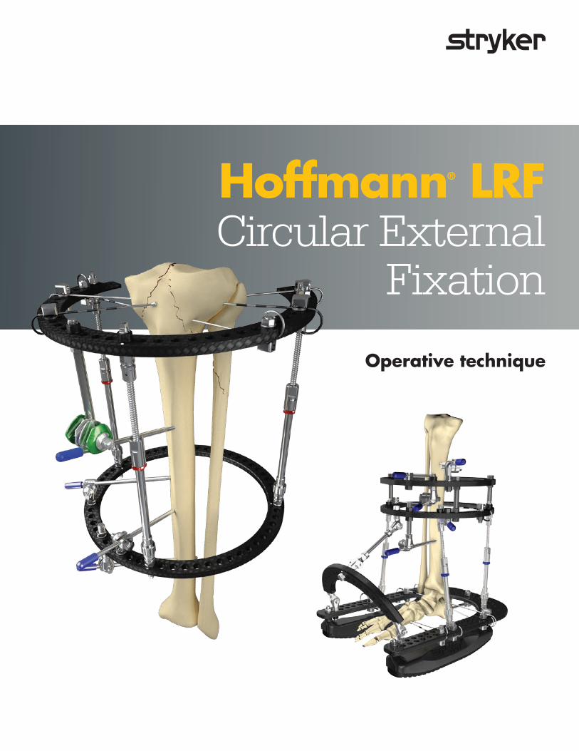
Operative technique
Hoffmann® LRF Circular External
Fixation
2
Hoffmann LRF Circular External Fixation | Operative technique
This publication sets forth detailed recommended procedures for using Stryker devices and instruments.
It offers guidance that you should heed, but, as with any such technical guide, each surgeon must consider the particular needs of each patient and make appropriate adjustments when and as required.
A workshop training is recommended prior to performing your first surgery. All non-sterile devices must be cleaned and sterilized before use. Follow the instructions provided in our cleaning and sterilization guide (L24002000).
Multi-component instruments must be disassembled for cleaning. Please refer to the corresponding assembly/disassembly instructions. Please remember that the compatibility of different product systems have not been tested unless specified otherwise in the product labeling.
See package insert (Instruction for Use) (V15013, V15034, V15011) for a complete list of potential adverse effects, contraindications, warnings and precautions. The surgeon must discuss all relevant risks including the finite lifetime of the device with the patient when necessary.
Hoffmann LRFCircular External FixationContents
1. Indications and contraindications . . . . . . . . . . . . 3
2. Introduction . . . . . . . . . . . . . . . . . . . . . . . . . . . . . . 5
3. Key components . . . . . . . . . . . . . . . . . . . . . . . . . . . 6 Rings . . . . . . . . . . . . . . . . . . . . . . . . . . . . . . . . . . . . . . 7 Ring types . . . . . . . . . . . . . . . . . . . . . . . . . . . . . . . . . . 8 Foot arches . . . . . . . . . . . . . . . . . . . . . . . . . . . . . . . . . 9 Rocker shoes . . . . . . . . . . . . . . . . . . . . . . . . . . . . . .10 Wire bolt, wire bolt adaptor . . . . . . . . . . . . . . . . . . 11 Apex pin adaptor, apex pin bolt . . . . . . . . . . . . . . . 12 Connecting nut . . . . . . . . . . . . . . . . . . . . . . . . . . . .13 Telescopic struts . . . . . . . . . . . . . . . . . . . . . . . . . . .14 Threaded rods . . . . . . . . . . . . . . . . . . . . . . . . . . . . .20 Hinge couplings . . . . . . . . . . . . . . . . . . . . . . . . . . . .21 Static struts . . . . . . . . . . . . . . . . . . . . . . . . . . . . . . .22
4. Key instruments . . . . . . . . . . . . . . . . . . . . . . . . . 23 Fixation components wrenches . . . . . . . . . . . . . . . 23 Wire tensioner . . . . . . . . . . . . . . . . . . . . . . . . . . . . .24 Recommended tension levels . . . . . . . . . . . . . . . . . 25 Wire tensioner disassembly . . . . . . . . . . . . . . . . . . . 25
5. Operative technique . . . . . . . . . . . . . . . . . . . . . 26 Sleeve system . . . . . . . . . . . . . . . . . . . . . . . . . . . . . .27
6. Frame examples . . . . . . . . . . . . . . . . . . . . . . . . . 30 Static foot & ankle frame . . . . . . . . . . . . . . . . . . . . 32 Tibial shaft frame . . . . . . . . . . . . . . . . . . . . . . . . . .34 Proximal tibial (plateau) frame . . . . . . . . . . . . . . . . 36 Distal tibial frame . . . . . . . . . . . . . . . . . . . . . . . . . .38 Distal radius frame. . . . . . . . . . . . . . . . . . . . . . . . . .40
Note: For a complete overview of the entire Hoffmann LRF System, it is recommended that the user also references the Hoffmann LRF Gradual Correction operative technique (H-ST-2), Hoffmann LRF bone transport operative technique (H-ST-31), the Hoffmann LRF Hexapod operative technique (H-ST-34) the Patient Guide for External Fixation (H-PG-1), the Hoffmann LRF Hexapod Hole Offset Guide (H-ADI-1), and the Hoffmann LRF Web Application user manual (H-IFU-2).
3
Operative technique | Hoffmann LRF Circular External Fixation
Indications & contraindications
Indications for useThe Hoffmann LRF System is indicated in pediatric patients and adults for the treatment and fixation of:
• Open and closed fractures
• Post-traumatic joint contracture which has resulted in loss of range of motion
• Fractures and disease which generally may result in joint contractures or loss of range of motion and fractures requiring distraction
• Pseudoarthrosis or non-union of long bones
• Limb lengthening by epiphyseal, diaphyseal, or metaphyseal distraction
• Correction of bony or soft tissue deformity
• Correction of segmental bony or soft tissue defects
• Joint arthrodesis
• Management of communicated intra-articular fractures of the distal radius
• Bone transport
The Hoffmann LRF System is indicated in adults for:
• Osteotomy
• Revision procedure where other treatments or devices have been unsuccessful
• Bone reconstruction procedures
• Fusions and replantations of the foot
• Charcot foot reconstruction
• Lisfranc dislocations
Intended useThe Hoffmann LRF (Limb Reconstruction Frame) System is intended for fixation of fractures, joint contractures, fusions, limb lengthening, deformity correction, bone and soft tissue reconstruction in pediatric patients and adults.
ContraindicationsSince external fixation devices are often used in emergency situations to treat patients with acute injuries, there are no absolute contraindications for use. The surgeon’s education, training and professional judgment must be relied upon to choose the most appropriate device and treatment for each individual patient. Whenever possible, the device chosen should be of a type indicated for the fracture being treated and/or for the procedure being utilized.
Conditions presenting an increased risk of failure include:
1. Insufficient quantity or quality of bone which would inhibit appropriate fixation of the device.
2. Compromised vascularity that would inhibit adequate blood supply to the fracture or operative site.
3. Previous history of infections.
4. Any neuromuscular deficit which could interfere with the patient’s ability to limit weight bearing.
5. Any neuromuscular deficit which places an unusually heavy load on the device during the healing period.
6. Malignancy in the fracture area.
7. Mental, physical or neurological conditions which may impair the patient’s ability to cooperate with the postoperative regimen.
4
Hoffmann LRF Circular External Fixation | Operative technique
Indications & contraindications
PrecautionsInformation for patient. Surgeons must instruct the patients to report any unusual changes of the operated site to their physician. Surgeon should immediately evaluate the patient if a change at the fracture site has been detected. The surgeon should evaluate the possibility of subsequent clinical failure, and discuss with the patient the need for reduced activity levels, and / or possible revision surgery in order to aid fracture healing.
The surgeon should discuss all physical and psychological limitations inherent in the use of external fracture fixation appliances with the patient. Particular attention should be given to premature weight bearing, activity levels and the necessity for periodic medical follow-up.
The surgeon must warn patients of surgical risks, and make them aware of possible adverse effects. The patient should be warned that the device cannot and does not replicate a normal healthy bone, that the device can break or become damaged as a result of strenuous activity or trauma.
WarningsSingle use devices cannot be reused, as they are not designed to perform as intended after the first usage. Changes in mechanical, physical or chemical characteristics introduced under conditions of repeated use, cleaning and re-sterilization may compromise the integrity of the design and/or materials leading to diminished safety, performance and/or compliance with relevant specifications. Please refer to the device label to identify single or multiple use and/or cleaning and re-sterilization release.
The Hoffmann LRF System is MR Unsafe
55
Introduction
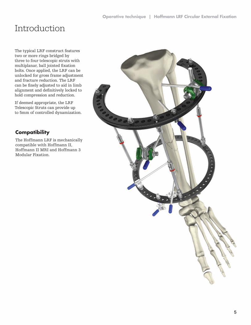
The typical LRF construct features two or more rings bridged by three to four telescopic struts with multiplanar, ball jointed fixation bolts. Once applied, the LRF can be unlocked for gross frame adjustment and fracture reduction. The LRF can be finely adjusted to aid in limb alignment and definitively locked to hold compression and reduction.
If deemed appropriate, the LRF Telescopic Struts can provide up to 5mm of controlled dynamization.
Compatibility The Hoffmann LRF is mechanically compatible with Hoffmann II, Hoffmann II MRI and Hoffmann 3 Modular Fixation.
Operative technique | Hoffmann LRF Circular External Fixation

6
Hoffmann LRF Circular External Fixation | Operative technique
Key components
7
Operative technique | Hoffmann LRF Circular External Fixation
Key components
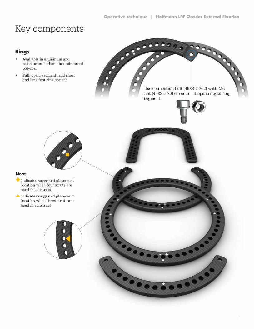
Use connection bolt (4933-1-702) with M6 nut (4933-1-701) to connect open ring to ring segment
Rings• Available in aluminum and
radiolucent carbon fiber reinforced polymer
• Full, open, segment, and short and long foot ring options
Note:
Indicates suggested placement location when four struts are used in construct
Indicates suggested placement location when three struts are used in construct
8
Hoffmann LRF Circular External Fixation | Operative technique
Key components
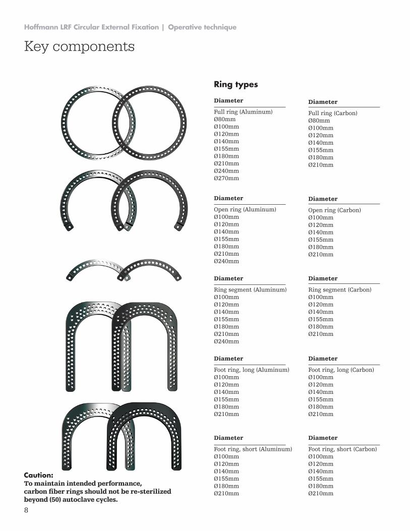
Ring types
Diameter
Full ring (Aluminum)Ø80mmØ100mmØ120mmØ140mmØ155mmØ180mmØ210mmØ240mmØ270mm
Diameter
Open ring (Aluminum)Ø100mmØ120mm Ø140mmØ155mmØ180mmØ210mmØ240mm
Diameter
Ring segment (Aluminum)Ø100mmØ120mm Ø140mmØ155mmØ180mmØ210mmØ240mm
Diameter
Foot ring, long (Aluminum)Ø100mmØ120mm Ø140mmØ155mmØ180mmØ210mm
Diameter
Foot ring, short (Aluminum) Ø100mmØ120mm Ø140mmØ155mmØ180mmØ210mm
Diameter
Full ring (Carbon)Ø80mmØ100mmØ120mmØ140mmØ155mmØ180mmØ210mm
Diameter
Open ring (Carbon)Ø100mmØ120mm Ø140mmØ155mmØ180mmØ210mm
Diameter
Ring segment (Carbon)Ø100mmØ120mm Ø140mmØ155mmØ180mmØ210mm
Diameter
Foot ring, long (Carbon)Ø100mmØ120mm Ø140mmØ155mmØ180mmØ210mm
Diameter
Foot ring, short (Carbon) Ø100mmØ120mm Ø140mmØ155mmØ180mmØ210mm
Caution: To maintain intended performance, carbon fiber rings should not be re-sterilized beyond (50) autoclave cycles.
9
Operative technique | Hoffmann LRF Circular External Fixation
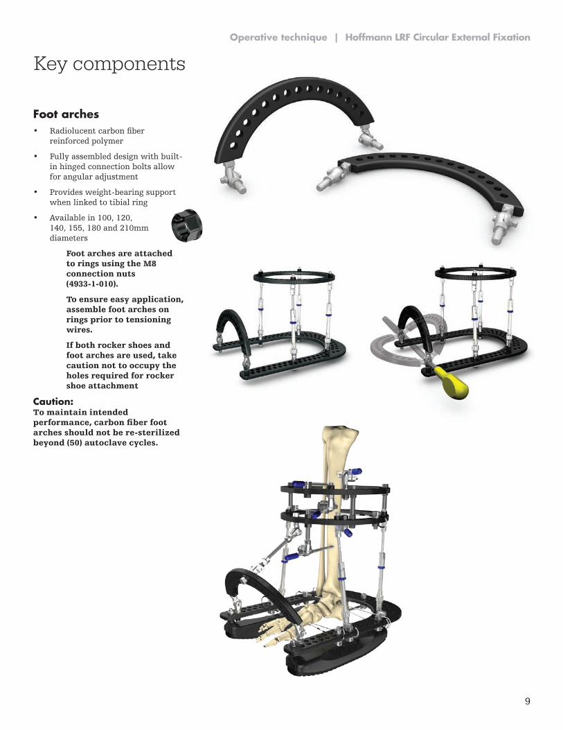
Foot arches• Radiolucent carbon fiber
reinforced polymer
• Fully assembled design with built-in hinged connection bolts allow for angular adjustment
• Provides weight-bearing support when linked to tibial ring
• Available in 100, 120, 140, 155, 180 and 210mm diameters
Foot arches are attached to rings using the M8 connection nuts (4933-1-010).
To ensure easy application, assemble foot arches on rings prior to tensioning wires.
If both rocker shoes and foot arches are used, take caution not to occupy the holes required for rocker shoe attachment
Caution: To maintain intended performance, carbon fiber foot arches should not be re-sterilized beyond (50) autoclave cycles.
Key components
10
Hoffmann LRF Circular External Fixation | Operative technique
Key components
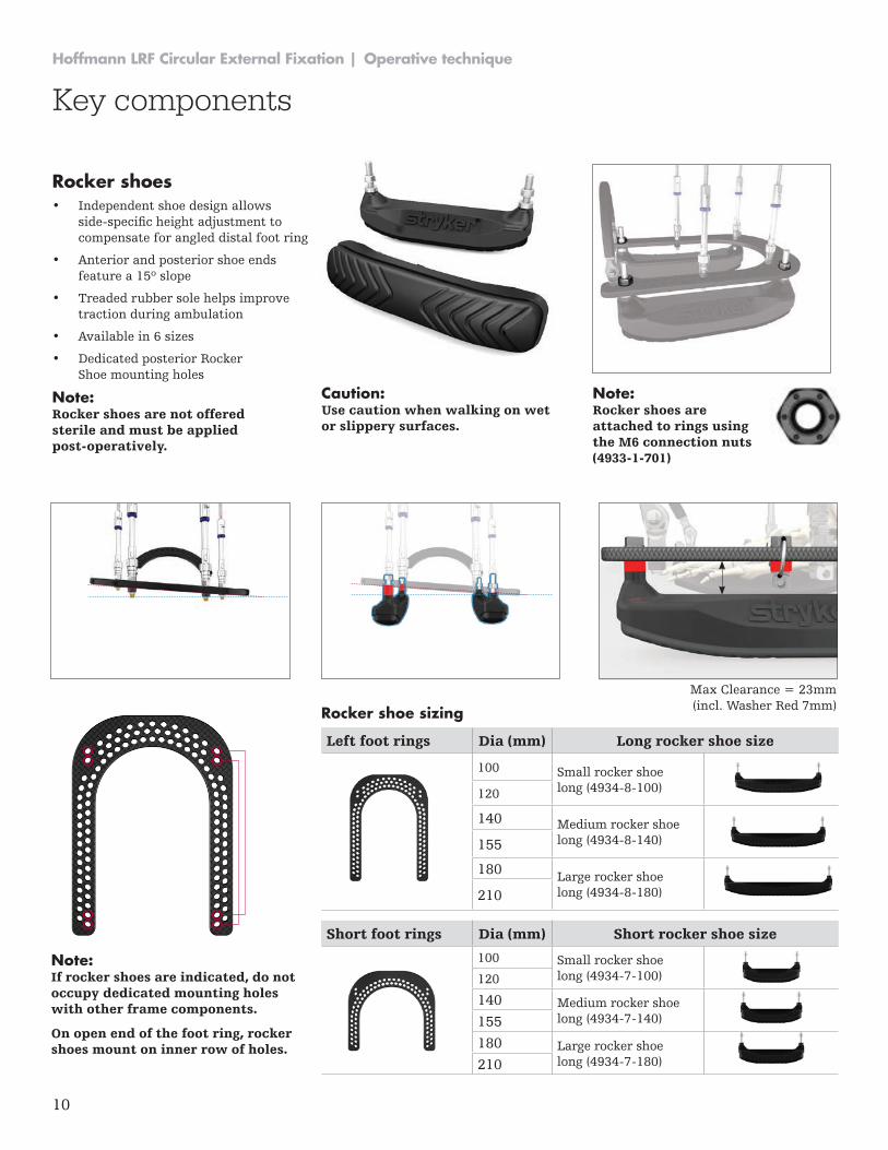
Rocker shoes• Independent shoe design allows
side-specific height adjustment to compensate for angled distal foot ring
• Anterior and posterior shoe ends feature a 15º slope
• Treaded rubber sole helps improve traction during ambulation
• Available in 6 sizes
• Dedicated posterior Rocker Shoe mounting holes
Note: Rocker shoes are not offered sterile and must be applied post-operatively.
Note: If rocker shoes are indicated, do not occupy dedicated mounting holes with other frame components.
On open end of the foot ring, rocker shoes mount on inner row of holes.
Caution: Use caution when walking on wet or slippery surfaces.
Note: Rocker shoes are attached to rings using the M6 connection nuts (4933-1-701)
Max Clearance = 23mm (incl. Washer Red 7mm)
Left foot rings Dia (mm) Long rocker shoe size
100 Small rocker shoe long (4934-8-100)120
140 Medium rocker shoe long (4934-8-140)155
180 Large rocker shoe long (4934-8-180)210
Short foot rings Dia (mm) Short rocker shoe size
100 Small rocker shoe long (4934-7-100)120
140 Medium rocker shoe long (4934-7-140)155
180 Large rocker shoe long (4934-7-180)210
Rocker shoe sizing
11
Operative technique | Hoffmann LRF Circular External Fixation
Key components
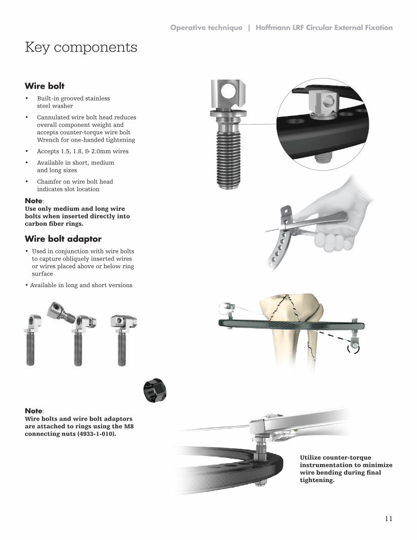
Wire bolt• Built-in grooved stainless
steel washer
• Cannulated wire bolt head reduces overall component weight and accepts counter-torque wire bolt Wrench for one-handed tightening
• Accepts 1.5, 1.8, & 2.0mm wires
• Available in short, medium and long sizes
• Chamfer on wire bolt head indicates slot location
Note: Use only medium and long wire bolts when inserted directly into carbon fiber rings.
Wire bolt adaptor• Used in conjunction with wire bolts
to capture obliquely inserted wires or wires placed above or below ring surface
• Available in long and short versions
Note: Wire bolts and wire bolt adaptors are attached to rings using the M8 connecting nuts (4933-1-010).
Utilize counter-torque instrumentation to minimize wire bending during final tightening.
12
Hoffmann LRF Circular External Fixation | Operative technique
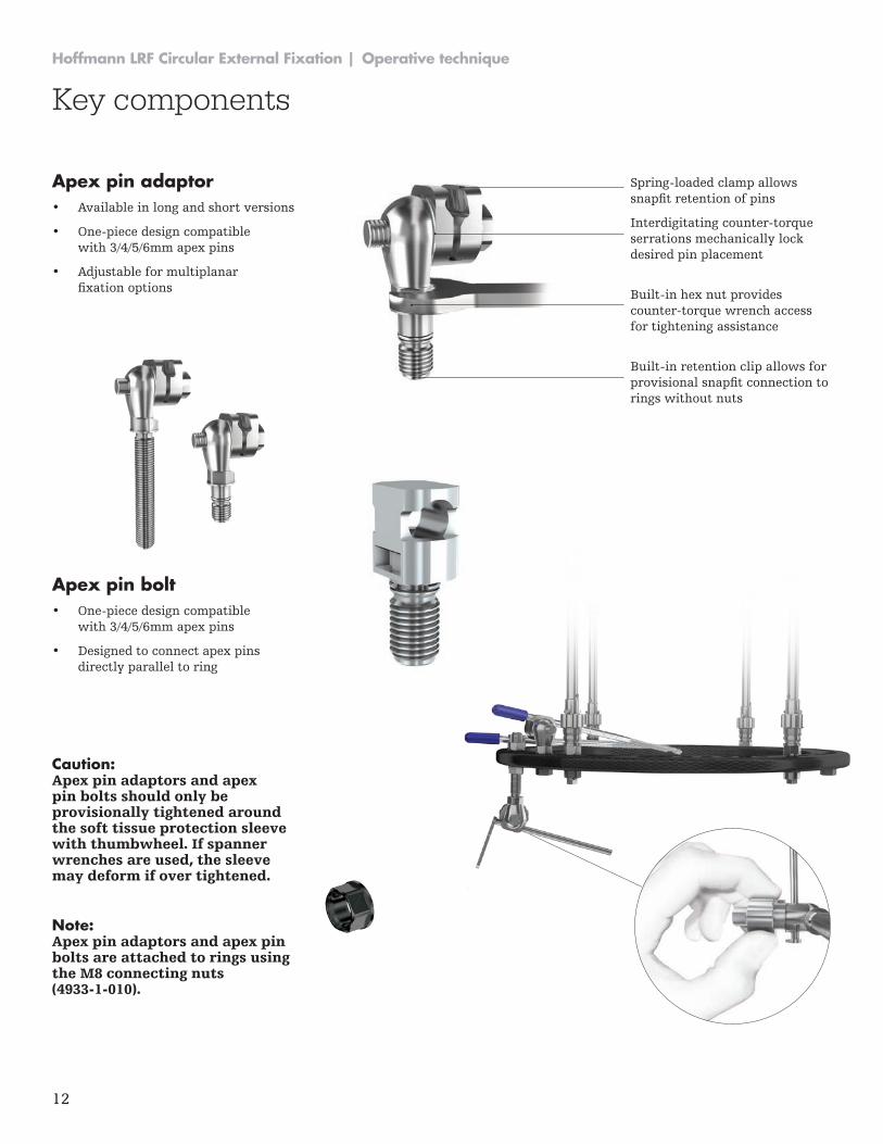
Apex pin adaptor• Available in long and short versions
• One-piece design compatible with 3/4/5/6mm apex pins
• Adjustable for multiplanar fixation options
Apex pin bolt• One-piece design compatible
with 3/4/5/6mm apex pins
• Designed to connect apex pins directly parallel to ring
Caution: Apex pin adaptors and apex pin bolts should only be provisionally tightened around the soft tissue protection sleeve with thumbwheel. If spanner wrenches are used, the sleeve may deform if over tightened.
Note: Apex pin adaptors and apex pin bolts are attached to rings using the M8 connecting nuts (4933-1-010).
Spring-loaded clamp allows snapfit retention of pins
Interdigitating counter-torque serrations mechanically lock desired pin placement
Built-in hex nut provides counter-torque wrench access for tightening assistance
Built-in retention clip allows for provisional snapfit connection to rings without nuts
Key components
13
Operative technique | Hoffmann LRF Circular External Fixation
Key components
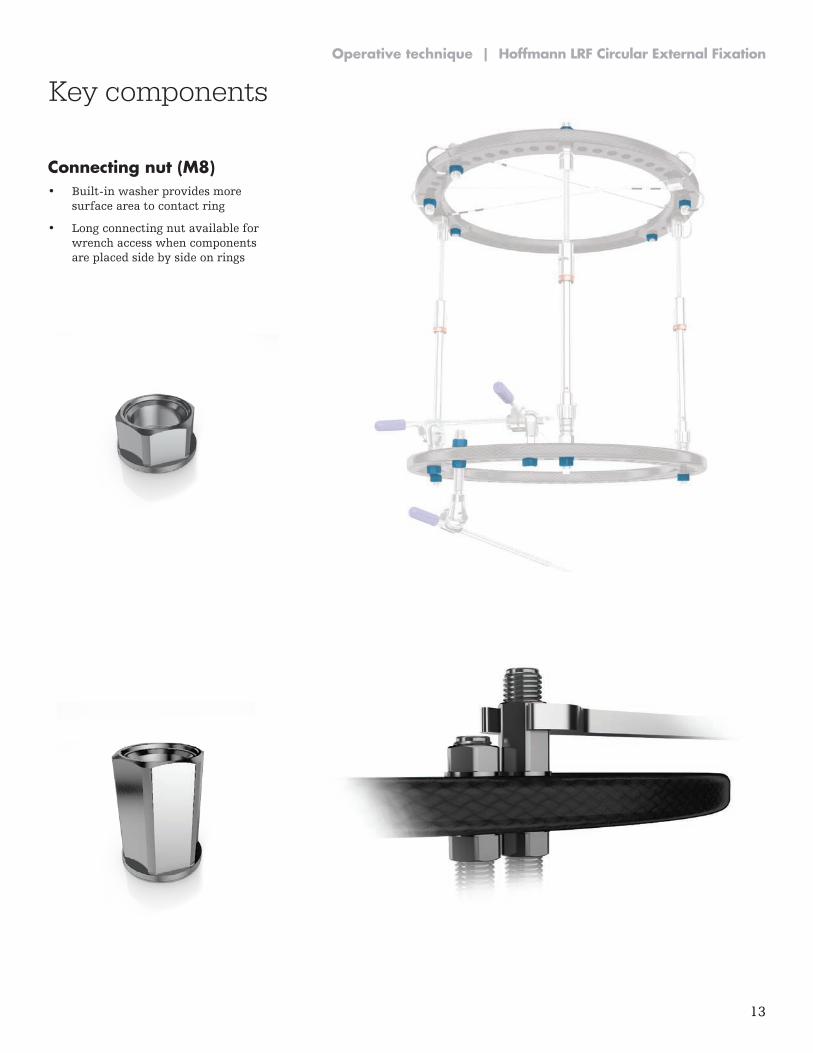
Connecting nut (M8)• Built-in washer provides more
surface area to contact ring
• Long connecting nut available for wrench access when components are placed side by side on rings
14
Hoffmann LRF Circular External Fixation | Operative technique
Key components
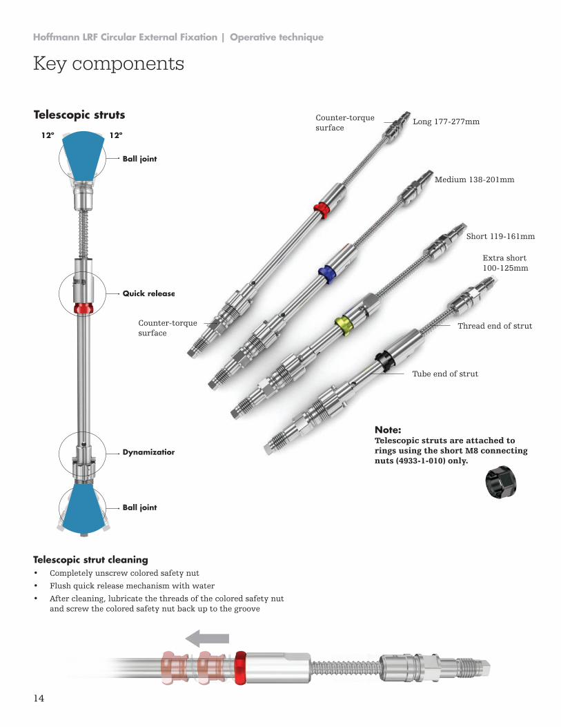
Telescopic struts
Telescopic strut cleaning• Completely unscrew colored safety nut
• Flush quick release mechanism with water
• After cleaning, lubricate the threads of the colored safety nut and screw the colored safety nut back up to the groove
12º 12º
Ball joint
Ball joint
Quick release
Dynamization wheel
Long 177-277mm
Medium 138-201mm
Short 119-161mm
Extra short 100-125mm
Thread end of strut
Tube end of strut
Counter-torque surface
Counter-torque surface
Note: Telescopic struts are attached to rings using the short M8 connecting nuts (4933-1-010) only.
15
Operative technique | Hoffmann LRF Circular External Fixation
Key components
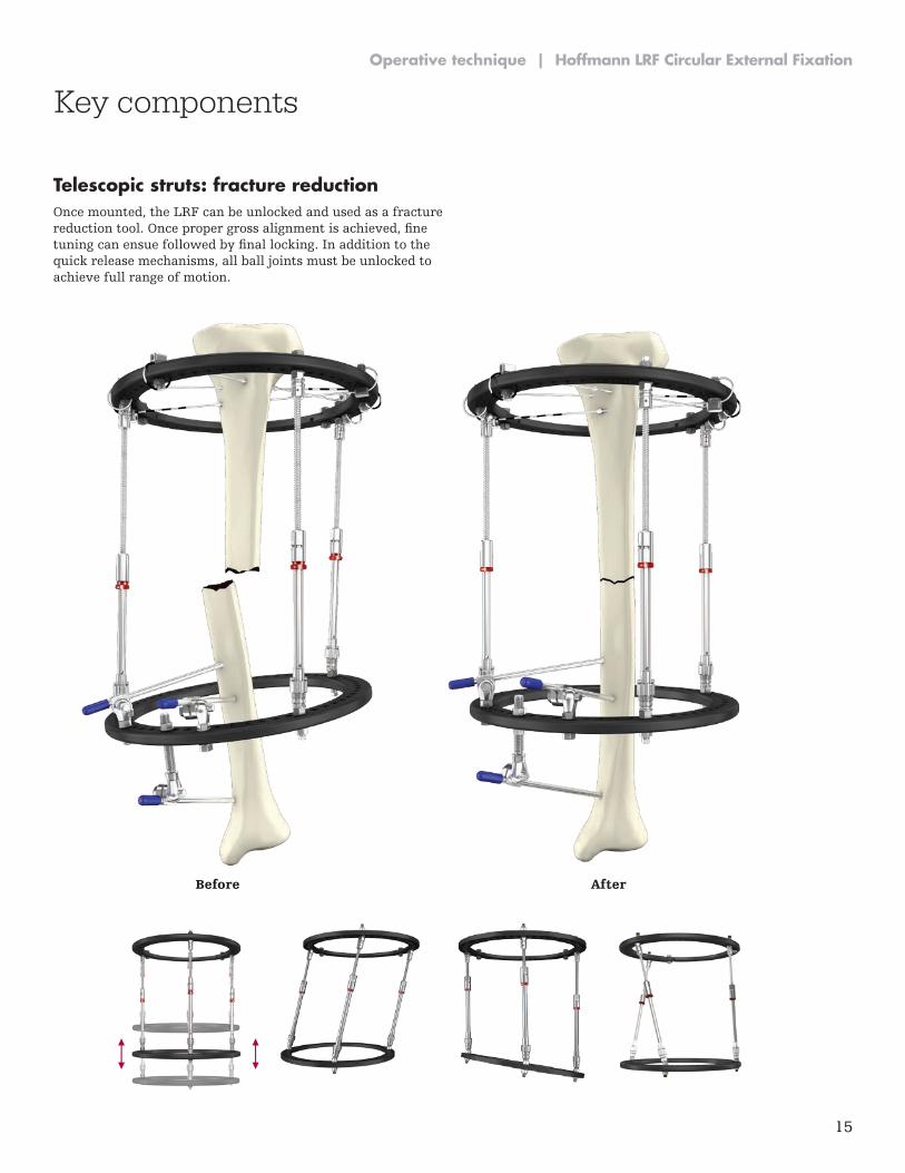
Telescopic struts: fracture reductionOnce mounted, the LRF can be unlocked and used as a fracture reduction tool. Once proper gross alignment is achieved, fine tuning can ensue followed by final locking. In addition to the quick release mechanisms, all ball joints must be unlocked to achieve full range of motion.
Before After
16
Hoffmann LRF Circular External Fixation | Operative technique
Key components
Finger grip only
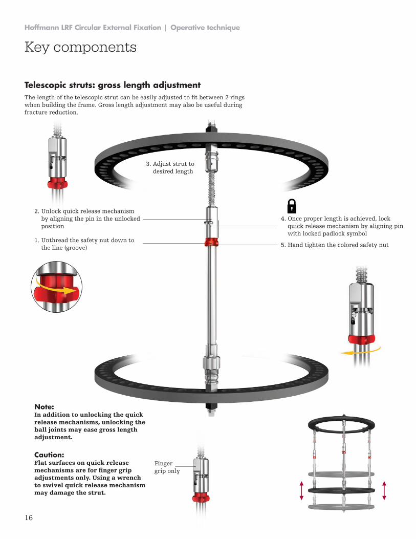
Telescopic struts: gross length adjustmentThe length of the telescopic strut can be easily adjusted to fit between 2 rings when building the frame. Gross length adjustment may also be useful during fracture reduction.
1. Unthread the safety nut down to the line (groove)
2. Unlock quick release mechanism by aligning the pin in the unlocked position
3. Adjust strut to desired length
4. Once proper length is achieved, lock quick release mechanism by aligning pin with locked padlock symbol
5. Hand tighten the colored safety nut
Note: In addition to unlocking the quick release mechanisms, unlocking the ball joints may ease gross length adjustment.
Caution: Flat surfaces on quick release mechanisms are for finger grip adjustments only. Using a wrench to swivel quick release mechanism may damage the strut.
17
Operative technique | Hoffmann LRF Circular External Fixation
Key components
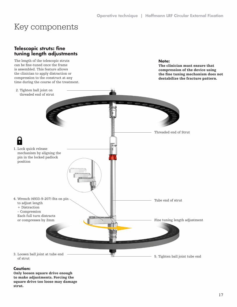
4. Once proper length is achieved, lock quick release mechanism by aligning pin with locked padlock symbol
4. Wrench (4933-9-207) fits on pin to adjust length + Distraction – Compression Each full turn distracts or compresses by 2mm
1. Lock quick release mechanism by aligning the pin in the locked padlock position
3. Loosen ball joint at tube end of strut
2. Tighten ball joint on threaded end of strut
Threaded end of Strut
Tube end of strut
Fine tuning length adjustment
5. Tighten ball joint tube end
Caution: Only loosen square drive enough to make adjustments. Forcing the square drive too loose may damage strut.
Telescopic struts: fine tuning length adjustmentsThe length of the telescopic struts can be fine-tuned once the frame is assembled. This feature allows the clinician to apply distraction or compression to the construct at any time during the course of the treatment.
Note: The clinician must ensure that compression of the device using the fine tuning mechanism does not destabilize the fracture pattern.
18
Hoffmann LRF Circular External Fixation | Operative technique
12º 12º
Key components
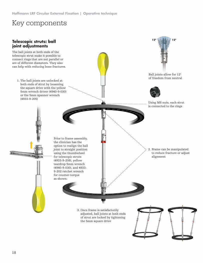
Telescopic struts: ball joint adjustmentsThe ball joints at both ends of the telescopic strut make it possible to connect rings that are not parallel or are of different diameters. They also can help with reducing bone fractures.
1. The ball joints are unlocked at both ends of strut by loosening the square drive with the yellow 5mm wrench driver (4940-9-030) or the 5mm spanner wrench (4933-9-205)
2. Frame can be manipulated to reduce fracture or adjust alignment
3. Once frame is satisfactorily adjusted, ball joints at both ends of strut are locked by tightening the 5mm square drive
Using M8 nuts, each strut is connected to the rings
Ball joints allow for 12o of freedom from neutral
Prior to frame assembly, the clinician has the option to realign the ball joint to straight position using the thumbwheel for telescopic struts (4933-9-208), yellow teardrop 5mm wrench (4940-9-030), and 4933-9-202 ratchet wrench for counter-torque as shown.
19
Operative technique | Hoffmann LRF Circular External Fixation
Key components
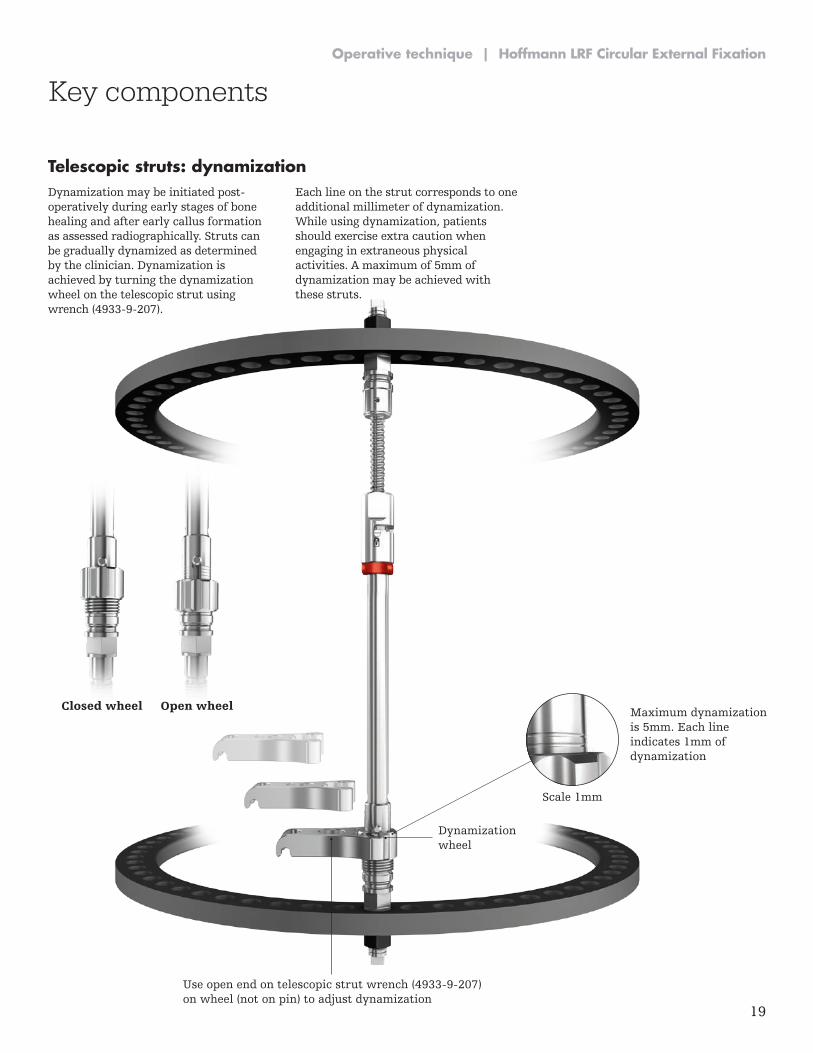
Scale 1mm
Maximum dynamization is 5mm. Each line indicates 1mm of dynamization
Dynamization wheel
Use open end on telescopic strut wrench (4933-9-207) on wheel (not on pin) to adjust dynamization
Telescopic struts: dynamizationDynamization may be initiated post-operatively during early stages of bone healing and after early callus formation as assessed radiographically. Struts can be gradually dynamized as determined by the clinician. Dynamization is achieved by turning the dynamization wheel on the telescopic strut using wrench (4933-9-207).
Each line on the strut corresponds to one additional millimeter of dynamization. While using dynamization, patients should exercise extra caution when engaging in extraneous physical activities. A maximum of 5mm of dynamization may be achieved with these struts.
Closed wheel Open wheel
20
Hoffmann LRF Circular External Fixation | Operative technique
Key components
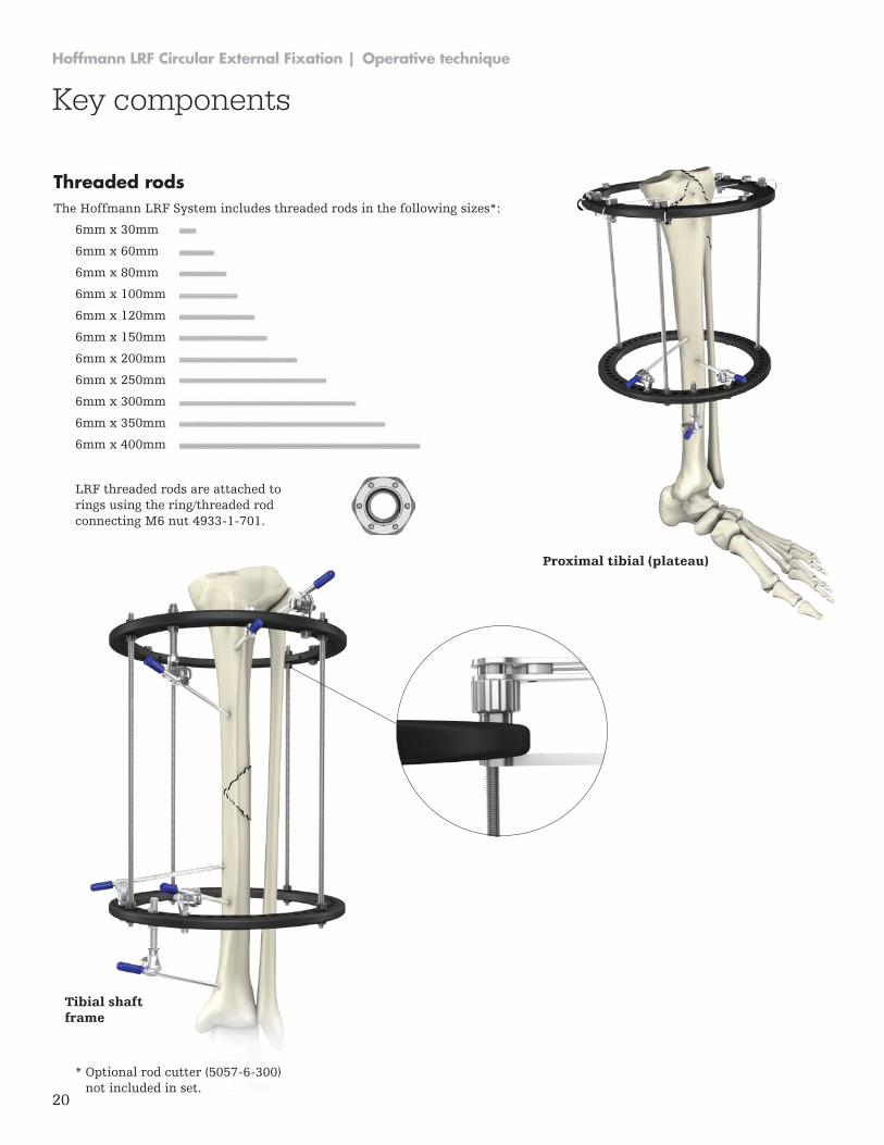
Threaded rodsThe Hoffmann LRF System includes threaded rods in the following sizes*:
* Optional rod cutter (5057-6-300) not included in set.
LRF threaded rods are attached to rings using the ring/threaded rod connecting M6 nut 4933-1-701.
Proximal tibial (plateau)
6mm x 30mm
6mm x 60mm
6mm x 80mm
6mm x 100mm
6mm x 120mm
6mm x 150mm
6mm x 200mm
6mm x 250mm
6mm x 300mm
6mm x 350mm
6mm x 400mm
Tibial shaft frame
21
Operative technique | Hoffmann LRF Circular External Fixation
Key components
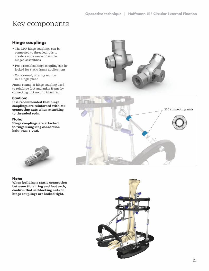
Hinge couplings• The LRF hinge couplings can be
connected to threaded rods to create a wide range of simple hinged assemblies
• Pre-assembled hinge coupling can be locked for static frame applications
• Constrained, offering motion in a single plane
Frame example: hinge coupling used to reinforce foot and ankle frame by connecting foot arch to tibial ring
Caution: It is recommended that hinge couplings are reinforced with M6 connecting nuts when attaching to threaded rods.
Note: Hinge couplings are attached to rings using ring connection bolt (4933-1-702).
Note: When building a static connection between tibial ring and foot arch, confirm that self-locking nuts on hinge couplings are locked tight.
M6 connecting nuts
22
Hoffmann LRF Circular External Fixation | Operative technique
Key components
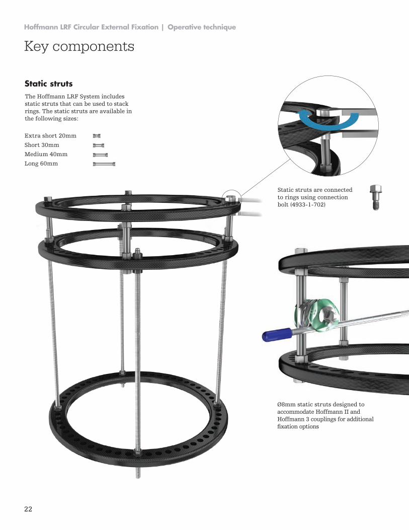
Ø8mm static struts designed to accommodate Hoffmann II and Hoffmann 3 couplings for additional fixation options
Static struts are connected to rings using connection bolt (4933-1-702)
Static strutsThe Hoffmann LRF System includes static struts that can be used to stack rings. The static struts are available in the following sizes:
Extra short 20mm
Short 30mm
Medium 40mm
Long 60mm
23
Operative technique | Hoffmann LRF Circular External Fixation
Key instruments
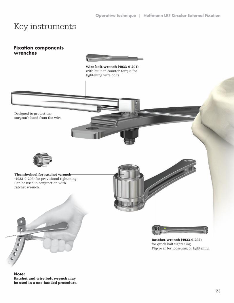
Fixation components wrenches
Wire bolt wrench (4933-9-201) with built-in counter-torque for tightening wire bolts
Ratchet wrench (4933-9-202) for quick bolt tightening. Flip over for loosening or tightening.
Thumbwheel for ratchet wrench (4933-9-203) for provisional tightening. Can be used in conjunction with ratchet wrench.
Note: Ratchet and wire bolt wrench may be used in a one-handed procedure.
Designed to protect the surgeon’s hand from the wire
24
Hoffmann LRF Circular External Fixation | Operative technique
Key instruments
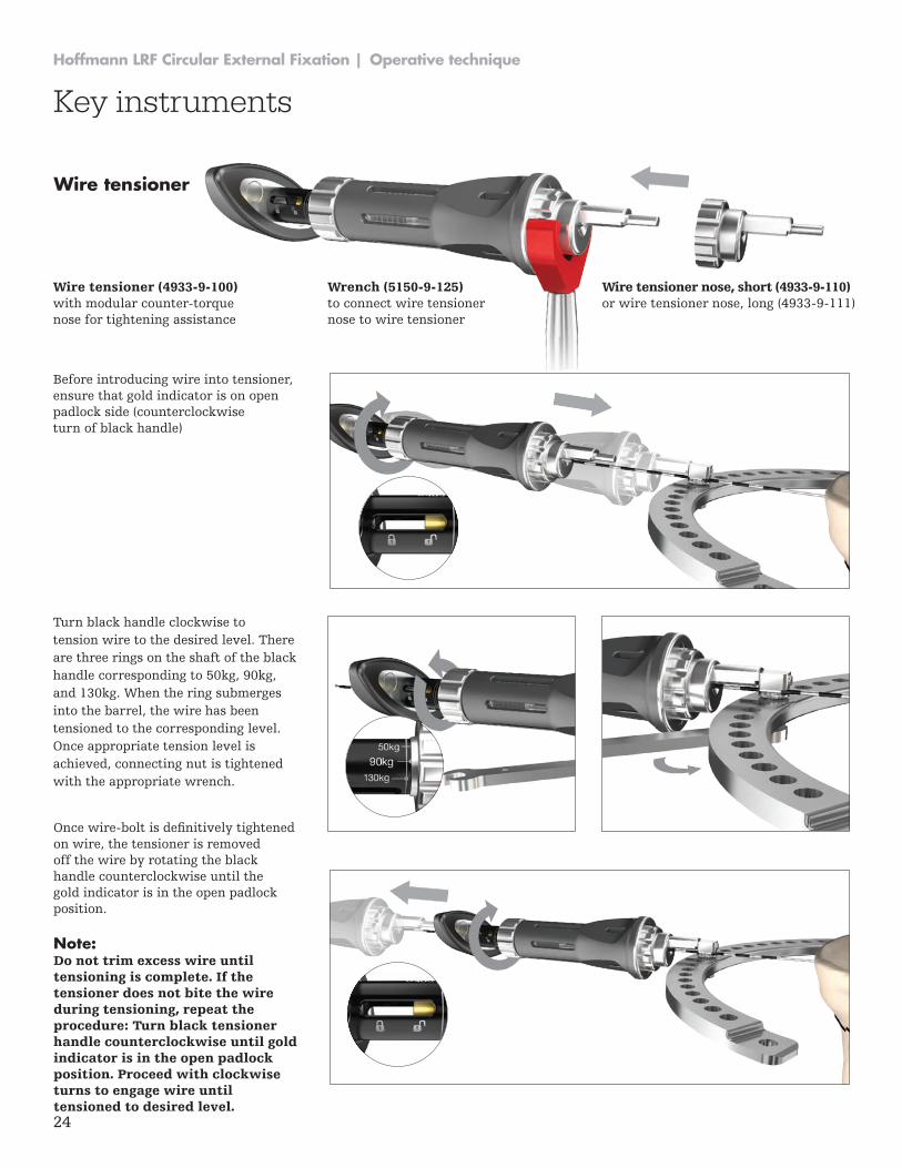
Turn black handle clockwise to tension wire to the desired level. There are three rings on the shaft of the black handle corresponding to 50kg, 90kg, and 130kg. When the ring submerges into the barrel, the wire has been tensioned to the corresponding level. Once appropriate tension level is achieved, connecting nut is tightened with the appropriate wrench.
Wire tensioner (4933-9-100) with modular counter-torque nose for tightening assistance
Before introducing wire into tensioner, ensure that gold indicator is on open padlock side (counterclockwise turn of black handle)
Wire tensioner nose, short (4933-9-110) or wire tensioner nose, long (4933-9-111)
Wrench (5150-9-125) to connect wire tensioner nose to wire tensioner
Wire tensioner
Once wire-bolt is definitively tightened on wire, the tensioner is removed off the wire by rotating the black handle counterclockwise until the gold indicator is in the open padlock position.
Note: Do not trim excess wire until tensioning is complete. If the tensioner does not bite the wire during tensioning, repeat the procedure: Turn black tensioner handle counterclockwise until gold indicator is in the open padlock position. Proceed with clockwise turns to engage wire until tensioned to desired level.
25
Operative technique | Hoffmann LRF Circular External Fixation
Key instruments
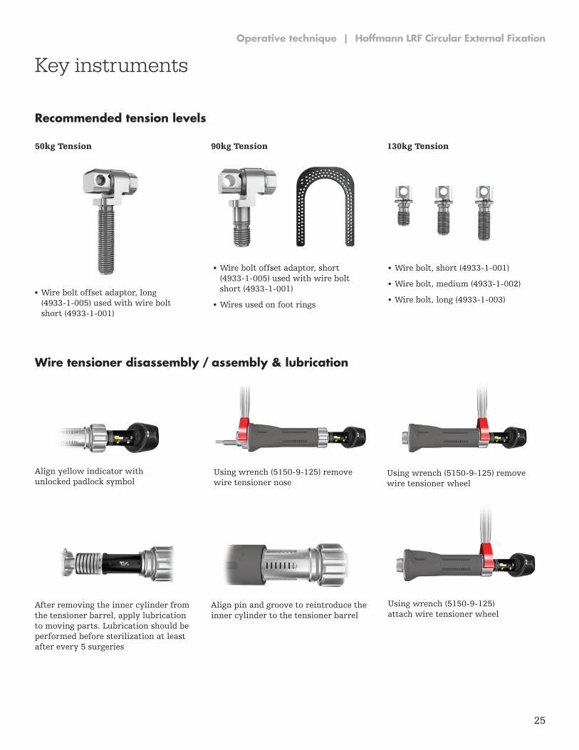
Wire tensioner disassembly / assembly & lubrication
Using wrench (5150-9-125) remove wire tensioner nose
Using wrench (5150-9-125) remove wire tensioner wheel
After removing the inner cylinder from the tensioner barrel, apply lubrication to moving parts. Lubrication should be performed before sterilization at least after every 5 surgeries
Align pin and groove to reintroduce the inner cylinder to the tensioner barrel
Using wrench (5150-9-125) attach wire tensioner wheel
Align yellow indicator with unlocked padlock symbol
50kg Tension 90kg Tension 130kg Tension
• Wire bolt offset adaptor, long (4933-1-005) used with wire bolt short (4933-1-001)
• Wire bolt, short (4933-1-001)
• Wire bolt, medium (4933-1-002)
• Wire bolt, long (4933-1-003)
• Wire bolt offset adaptor, short (4933-1-005) used with wire bolt short (4933-1-001)
• Wires used on foot rings
Recommended tension levels

26
Hoffmann LRF Circular External Fixation | Operative technique
26
Operative technique
27
Operative technique | Hoffmann LRF Circular External Fixation
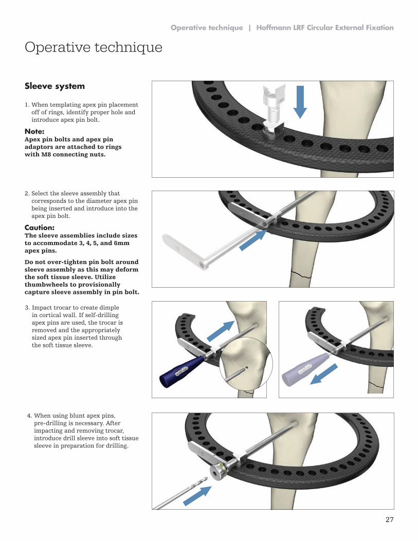
Sleeve system
1. When templating apex pin placement off of rings, identify proper hole and introduce apex pin bolt.
Note: Apex pin bolts and apex pin adaptors are attached to rings with M8 connecting nuts.
2. Select the sleeve assembly that corresponds to the diameter apex pin being inserted and introduce into the apex pin bolt.
Caution: The sleeve assemblies include sizes to accommodate 3, 4, 5, and 6mm apex pins.
Do not over-tighten pin bolt around sleeve assembly as this may deform the soft tissue sleeve. Utilize thumbwheels to provisionally capture sleeve assembly in pin bolt.
3. Impact trocar to create dimple in cortical wall. If self-drilling apex pins are used, the trocar is removed and the appropriately sized apex pin inserted through the soft tissue sleeve.
4. When using blunt apex pins, pre-drilling is necessary. After impacting and removing trocar, introduce drill sleeve into soft tissue sleeve in preparation for drilling.
Operative technique
28
Hoffmann LRF Circular External Fixation | Operative technique
Operative technique
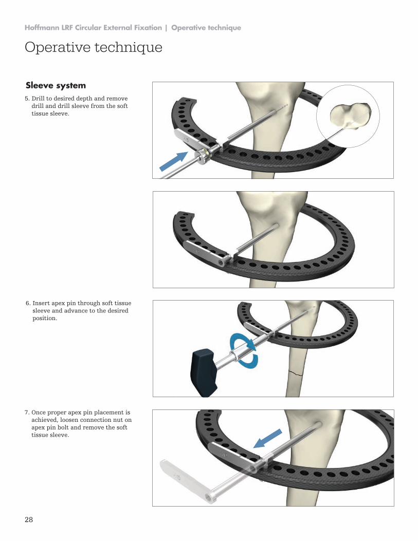
Sleeve system5. Drill to desired depth and remove
drill and drill sleeve from the soft tissue sleeve.
7. Once proper apex pin placement is achieved, loosen connection nut on apex pin bolt and remove the soft tissue sleeve.
6. Insert apex pin through soft tissue sleeve and advance to the desired position.

29
Operative technique | Hoffmann LRF Circular External Fixation
Operative technique
Sleeve system
8. Utilize counter-torque instrumentation to minimize pin bolt rotation during final tightening.

30
Hoffmann LRF Circular External Fixation | Operative technique
0860-2016 gamma3_long_nail_optech -proof 6

31
Operative technique | Hoffmann LRF Circular External Fixation
Frame examples
0860-2016 gamma3_long_nail_optech -proof 6
32
Hoffmann LRF Circular External Fixation | Operative technique
Frame examples
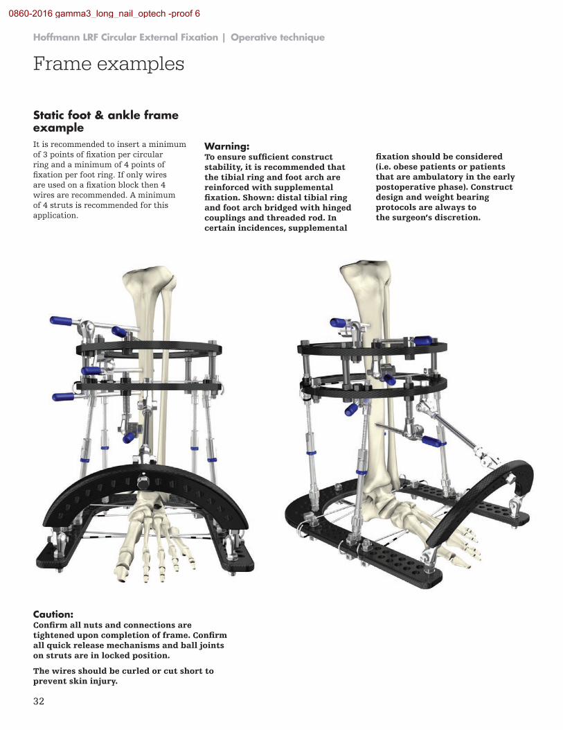
Static foot & ankle frame exampleIt is recommended to insert a minimum of 3 points of fixation per circular ring and a minimum of 4 points of fixation per foot ring. If only wires are used on a fixation block then 4 wires are recommended. A minimum of 4 struts is recommended for this application.
Warning: To ensure sufficient construct stability, it is recommended that the tibial ring and foot arch are reinforced with supplemental fixation. Shown: distal tibial ring and foot arch bridged with hinged couplings and threaded rod. In certain incidences, supplemental
fixation should be considered (i.e. obese patients or patients that are ambulatory in the early postoperative phase). Construct design and weight bearing protocols are always to the surgeon’s discretion.
Caution: Confirm all nuts and connections are tightened upon completion of frame. Confirm all quick release mechanisms and ball joints on struts are in locked position.
The wires should be curled or cut short to prevent skin injury.
0860-2016 gamma3_long_nail_optech -proof 6
33
Operative technique | Hoffmann LRF Circular External Fixation
Frame examples
Components used
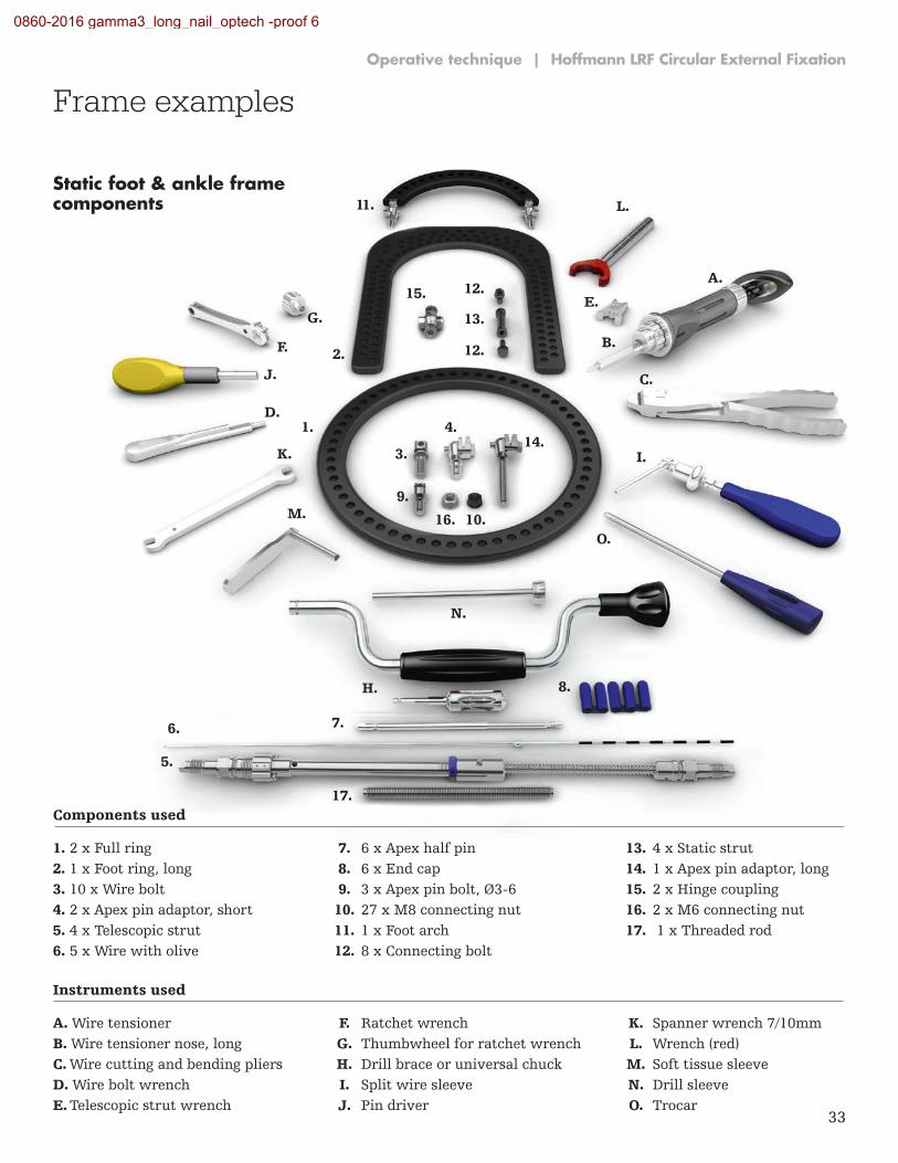
1. 2 x Full ring 7. 6 x Apex half pin 13. 4 x Static strut 2. 1 x Foot ring, long 8. 6 x End cap 14. 1 x Apex pin adaptor, long 3. 10 x Wire bolt 9. 3 x Apex pin bolt, Ø3-6 15. 2 x Hinge coupling 4. 2 x Apex pin adaptor, short 10. 27 x M8 connecting nut 16. 2 x M6 connecting nut 5. 4 x Telescopic strut 11. 1 x Foot arch 17. 1 x Threaded rod 6. 5 x Wire with olive 12. 8 x Connecting bolt
Instruments used
A. Wire tensioner F. Ratchet wrench K. Spanner wrench 7/10mm B. Wire tensioner nose, long G. Thumbwheel for ratchet wrench L. Wrench (red) C. Wire cutting and bending pliers H. Drill brace or universal chuck M. Soft tissue sleeve D. Wire bolt wrench I. Split wire sleeve N. Drill sleeve E. Telescopic strut wrench J. Pin driver O. Trocar
3.
5.
6.
4.
11. L.
7.
8.
9.
10.
1.
2.
A.
B.
C.
D.
K.
E.
F.
J.
G.
H.
M.
N.
O.
I.
Static foot & ankle frame components
14.
12.
13.
12.
17.
16.
15.
0860-2016 gamma3_long_nail_optech -proof 6
34
Hoffmann LRF Circular External Fixation | Operative technique
Frame examples
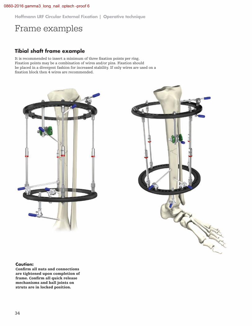
Caution: Confirm all nuts and connections are tightened upon completion of frame. Confirm all quick release mechanisms and ball joints on struts are in locked position.
Tibial shaft frame exampleIt is recommended to insert a minimum of three fixation points per ring. Fixation points may be a combination of wires and/or pins. Fixation should be placed in a divergent fashion for increased stability. If only wires are used on a fixation block then 4 wires are recommended.
0860-2016 gamma3_long_nail_optech -proof 6
35
Operative technique | Hoffmann LRF Circular External Fixation
1.
2.
3.G.
F.
H.
I.
4. 5.
7. 8.
9.10.
6.
12.13.
14.
11.
Tibial shaft frame components
B.
C.
D.
A.
E.
Components used
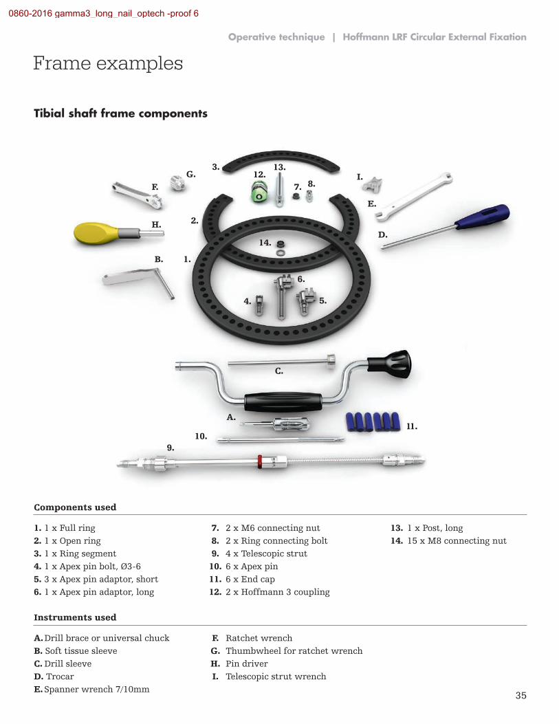
1. 1 x Full ring 7. 2 x M6 connecting nut 13. 1 x Post, long 2. 1 x Open ring 8. 2 x Ring connecting bolt 14. 15 x M8 connecting nut 3. 1 x Ring segment 9. 4 x Telescopic strut 4. 1 x Apex pin bolt, Ø3-6 10. 6 x Apex pin 5. 3 x Apex pin adaptor, short 11. 6 x End cap 6. 1 x Apex pin adaptor, long 12. 2 x Hoffmann 3 coupling
Instruments used
A. Drill brace or universal chuck F. Ratchet wrench B. Soft tissue sleeve G. Thumbwheel for ratchet wrench C. Drill sleeve H. Pin driver D. Trocar I. Telescopic strut wrench E. Spanner wrench 7/10mm
Frame examples
0860-2016 gamma3_long_nail_optech -proof 6
36
Hoffmann LRF Circular External Fixation | Operative technique
Frame examples
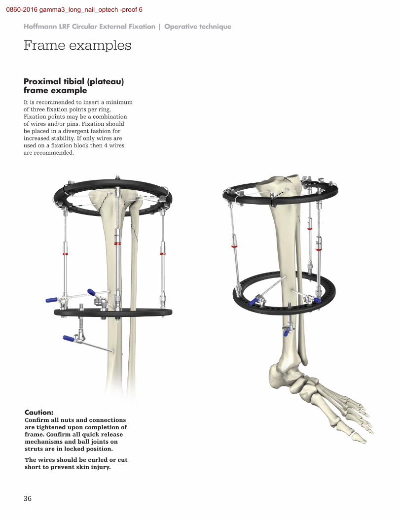
Proximal tibial (plateau) frame exampleIt is recommended to insert a minimum of three fixation points per ring. Fixation points may be a combination of wires and/or pins. Fixation should be placed in a divergent fashion for increased stability. If only wires are used on a fixation block then 4 wires are recommended.
Caution: Confirm all nuts and connections are tightened upon completion of frame. Confirm all quick release mechanisms and ball joints on struts are in locked position.
The wires should be curled or cut short to prevent skin injury.
0860-2016 gamma3_long_nail_optech -proof 6
37
1.
2.
A.
B.
C.
D.
K.
E.
F.
J.
G.
H.
M.
N.
I.
O.
3.
4.
5.
8.
9.
10.11.
12.
13.
6.
7.
Proximal tibial frame components
L.
Components used
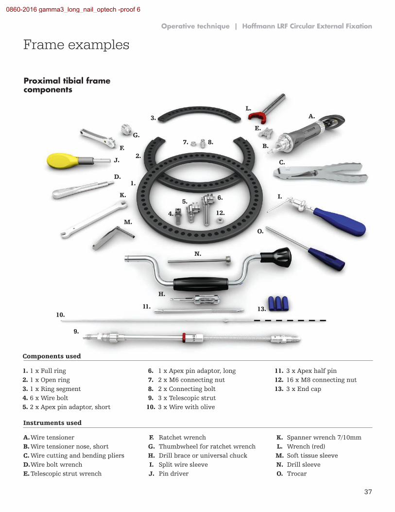
1. 1 x Full ring 6. 1 x Apex pin adaptor, long 11. 3 x Apex half pin 2. 1 x Open ring 7. 2 x M6 connecting nut 12. 16 x M8 connecting nut 3. 1 x Ring segment 8. 2 x Connecting bolt 13. 3 x End cap 4. 6 x Wire bolt 9. 3 x Telescopic strut 5. 2 x Apex pin adaptor, short 10. 3 x Wire with olive
Instruments used
A. Wire tensioner F. Ratchet wrench K. Spanner wrench 7/10mm B. Wire tensioner nose, short G. Thumbwheel for ratchet wrench L. Wrench (red) C. Wire cutting and bending pliers H. Drill brace or universal chuck M. Soft tissue sleeve D. Wire bolt wrench I. Split wire sleeve N. Drill sleeve E. Telescopic strut wrench J. Pin driver O. Trocar
Frame examplesOperative technique | Hoffmann LRF Circular External Fixation
0860-2016 gamma3_long_nail_optech -proof 6
38
Hoffmann LRF Circular External Fixation | Operative technique
Frame examples
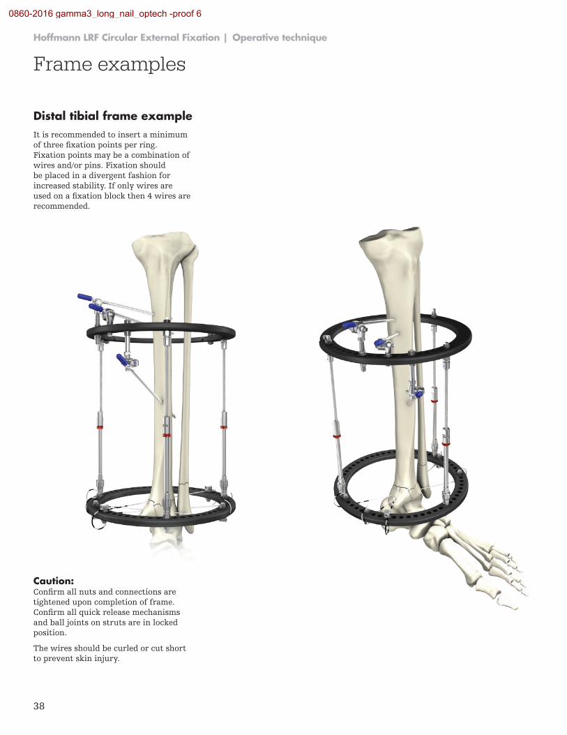
It is recommended to insert a minimum of three fixation points per ring. Fixation points may be a combination of wires and/or pins. Fixation should be placed in a divergent fashion for increased stability. If only wires are used on a fixation block then 4 wires are recommended.
Caution: Confirm all nuts and connections are tightened upon completion of frame. Confirm all quick release mechanisms and ball joints on struts are in locked position.
The wires should be curled or cut short to prevent skin injury.
Distal tibial frame example
0860-2016 gamma3_long_nail_optech -proof 6
39
1.
2.
A.
B.
C.
D.
K.
E.
F.
J.
G.
H.
M.
N.
I.
O.
3.
4.
5.
8.
9.
10.11.
12.
13.
6.
7.
L.
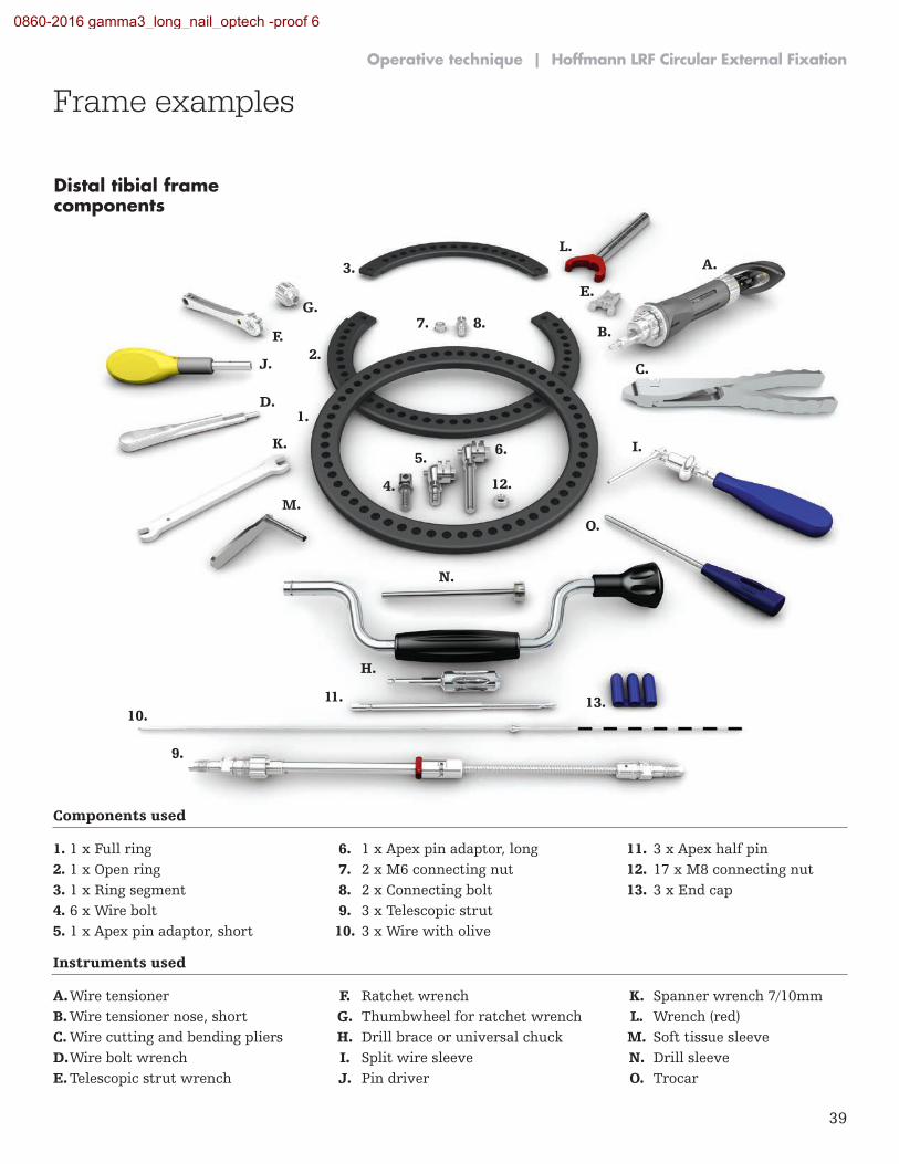
Distal tibial frame components
Components used
1. 1 x Full ring 6. 1 x Apex pin adaptor, long 11. 3 x Apex half pin 2. 1 x Open ring 7. 2 x M6 connecting nut 12. 17 x M8 connecting nut 3. 1 x Ring segment 8. 2 x Connecting bolt 13. 3 x End cap 4. 6 x Wire bolt 9. 3 x Telescopic strut 5. 1 x Apex pin adaptor, short 10. 3 x Wire with olive
Instruments used
A. Wire tensioner F. Ratchet wrench K. Spanner wrench 7/10mm B. Wire tensioner nose, short G. Thumbwheel for ratchet wrench L. Wrench (red) C. Wire cutting and bending pliers H. Drill brace or universal chuck M. Soft tissue sleeve D. Wire bolt wrench I. Split wire sleeve N. Drill sleeve E. Telescopic strut wrench J. Pin driver O. Trocar
Operative technique | Hoffmann LRF Circular External Fixation
Frame examples
0860-2016 gamma3_long_nail_optech -proof 6
40
Hoffmann LRF Circular External Fixation | Operative technique
Frame examples
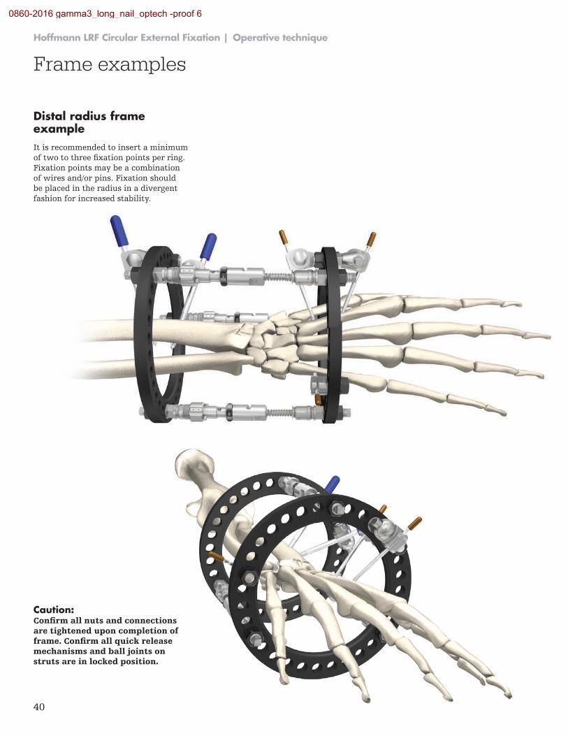
Distal radius frame exampleIt is recommended to insert a minimum of two to three fixation points per ring. Fixation points may be a combination of wires and/or pins. Fixation should be placed in the radius in a divergent fashion for increased stability.
Caution: Confirm all nuts and connections are tightened upon completion of frame. Confirm all quick release mechanisms and ball joints on struts are in locked position.
0860-2016 gamma3_long_nail_optech -proof 6
41
2.
4.
7. 3.
5. 6.
1.
F.
A.
B.
G.
C. D.
E.
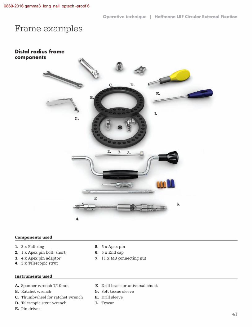
Distal radius frame components
H.
I.
Components used
1. 2 x Full ring 5. 5 x Apex pin 2. 1 x Apex pin bolt, short 6. 5 x End cap 3. 4 x Apex pin adaptor 7. 11 x M8 connecting nut 4. 3 x Telescopic strut
Instruments used
A. Spanner wrench 7/10mm F. Drill brace or universal chuck B. Ratchet wrench G. Soft tissue sleeve C. Thumbwheel for ratchet wrench H. Drill sleeve D. Telescopic strut wrench I. Trocar E. Pin driver
Operative technique | Hoffmann LRF Circular External Fixation
Frame examples
0860-2016 gamma3_long_nail_optech -proof 6

42
Hoffmann LRF Circular External Fixation | Operative technique
Notes:
0860-2016 gamma3_long_nail_optech -proof 6

43
Operative technique | Hoffmann LRF Circular External Fixation
Notes:
0860-2016 gamma3_long_nail_optech -proof 6

This document is intended solely for the use of healthcare professionals. A surgeon must always rely on his or her own professional clinical judgment when deciding whether to use a particular product when treating a particular patient. Stryker does not dispense medical advice and recommends that surgeons be trained in the use of any particular product before using it in surgery.
The information presented is intended to demonstrate a Stryker product. A surgeon must always refer to the package insert, product label and/or instructions for use, including the instructions for Cleaning and Sterilization (if applicable), before using any Stryker product. Products may not be available in all markets because product availability is subject to the regulatory and/or medical practices in individual markets. Please contact your Stryker representative if you have questions about the availability of Stryker products in your area.
Stryker Corporation or its divisions or other corporate affiliated entities own, use or have applied for the following trademarks or service marks: Apex, Hoffmann, Stryker. All other trademarks are trademarks of their respective owners or holders.
Content ID: H-ST-1_Rev. 2, 06-2016 Copyright © 2016 Stryker
Trauma & Extremities
Manufacturer:
Stryker GmbH Bohnackerweg 1 2545 Selzach Switzerland
stryker.com
0860-2016 gamma3_long_nail_optech -proof 6