Embed Size (px)
Citation preview
isell & Gossett a xylem brand
INSTRUCTION MANUAL
DN0162
REVISION H
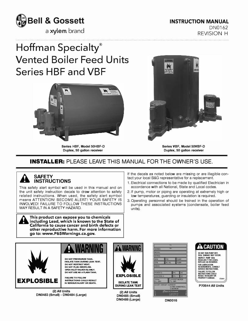
Hoffman Specialty®
Vented Boiler Feed Units Series HBF and VBF
Series HBF, Model 50HBF-D
Duplex, 50 gallon receiver
Series VBF, Model 50VBF-D
Duplex, 50 gallon receiver
INSTALLER: PLEASE LEAVE THIS MANUAL FOR THE OWNER'S USE.
A SAFETY INSTRUCTIONS
This safety alert symbol will be used in this manual and on the unit safety instruction decals to draw attention to safety related instructions. When used, the safety alert symbol means ATTENTION! BECOME ALERT! YOUR SAFETY IS INVOLVED! FAILURE TO FOLLOW THESE INSTRUCTIONS MAY RESULT IN A SAFETY HAZARD.
A This product can expose you to chemicals including Lead, which is known to the State of California to cause cancer and birth defects or other reproductive harm. For more information go to: www.P65Warnings.ca.gov.
WARNING DO NOT PRESSURIZE TANK.
ISOLATE TANK DURING LEAK TEST.
DO NOT RESTRICT VENT.
DO NOT PLUG OVERFLOW.
OPEN INLET VALVES SLOWLY.
DO NOT USE AS A FLASH TANK.
If the decals as noted below are missing or are illegible contact your local B&G representative for a replacement.
1. Electrical connections to be made by qualified Electrician inaccordance with all National, State and Local codes.
2. If pump, motor or piping are operating at extremely high or low temperatures, guarding or insulation is required.
3. Operating personnel should be trained in the operation of pumps and associated systems (condensate, boiler feedunits).
WARNING SERIES TM
MODEL
SERIAL
GPM PSI
CFM IN. HG.
OWGS
POWER V,
PUMP
PUMP
PH. HZ
ACAUTION DO NOT RUN PUMP DRY, SEAL DAMAGE MAY OCCUR.
INSPECT PUMP SEAL REGULARLY FOR LEAKS, REPLACE AS REQUIRED.
EXPLOSIBLE FALURE TO FOU.OW
INSTRUCTIONS COULD RESULT
IN SERIOUS INJURY OR DEATH.
EXPLOSIBLE
ISOLATE TANK
DURING LEAK TEST
CONTROL V. PH. 1 HZ
TOTAL
F.l.AMP.
SHORT CIRCUIT CURRENT:
kA RMS SYMMETRICAL,
V. MAXIMUM
FOR WBRICATION REQUIREMENTS, CONSULT SERVICE INSTRUCTIONS.
FAILURE TO FOLLOW INSTRUCTIONS COULD RESULT IN INJURY OR PROPERTY DAMAGE.
P70644 All Units
(2) All UnitsDN0483 (Small) - DN0484 (Large)
(2) All UnitsDN0485 (Small) DN0486 (Large) DN0016
DESCRIPTIONBoiler feed units are designed to pump water into an operatingboiler. The pumps are controlled by level controls on the boiler.Boiler feed units are normally sized to accommodate systemsurges and also to provide for the addition of fresh water asrequired.Series VBF and HBF units are standardized feed units intendedfor application to low pressure boilers. Pump discharge pres-sures are 20 psi (1.4 bar), 25 psi (1.7 bar) and 30 psi (2 bar) de-pending upon model specified. Receivers are heavy gauge, non-code steel. HBF receivers are provided with the Hoffguard™corrosion resistant coating for longer life.Receivers are non-code steel.
PRELIMINARY INSPECTION
Assure that there is no shipping damage.
Assure that nameplate ratings agree with job specificationsand actual conditions.
Remove all plastic shipping plugs from receiver and pumps.
HANDLING
Use care in installing unit.
LOCATION
Place unit for easy access to all parts. Allow adequate spacefor servicing. Check ambient conditions.
NOTICE / TEMPERATURE LIMITS
Motors are designed to operate in 104˚F (40˚C) max. ambient.Insulate or ventilate as required.
PIPING (General)
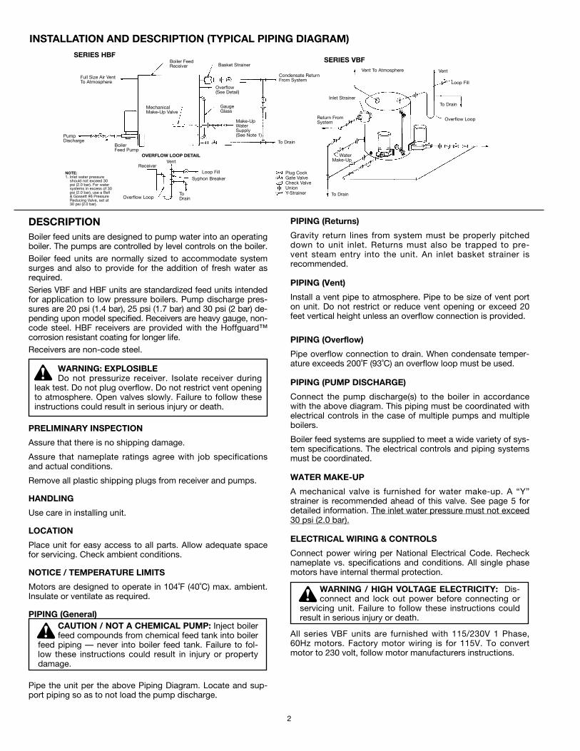
Pipe the unit per the above Piping Diagram. Locate and sup-port piping so as to not load the pump discharge.
PIPING (Returns)
Gravity return lines from system must be properly pitcheddown to unit inlet. Returns must also be trapped to pre-vent steam entry into the unit. An inlet basket strainer isrecommended.
PIPING (Vent)
Install a vent pipe to atmosphere. Pipe to be size of vent porton unit. Do not restrict or reduce vent opening or exceed 20feet vertical height unless an overflow connection is provided.
PIPING (Overflow)
Pipe overflow connection to drain. When condensate temper-ature exceeds 200˚F (93˚C) an overflow loop must be used.
PIPING (PUMP DISCHARGE)
Connect the pump discharge(s) to the boiler in accordancewith the above diagram. This piping must be coordinated withelectrical controls in the case of multiple pumps and multipleboilers.
Boiler feed systems are supplied to meet a wide variety of sys-tem specifications. The electrical controls and piping systemsmust be coordinated.
WATER MAKE-UP
A mechanical valve is furnished for water make-up. A “Y”strainer is recommended ahead of this valve. See page 5 fordetailed information. The inlet water pressure must not exceed30 psi (2.0 bar).
ELECTRICAL WIRING & CONTROLS
Connect power wiring per National Electrical Code. Rechecknameplate vs. specifications and conditions. All single phasemotors have internal thermal protection.
All series VBF units are furnished with 115/230V 1 Phase,60Hz motors. Factory motor wiring is for 115V. To convertmotor to 230 volt, follow motor manufacturers instructions.
CAUTION / NOT A CHEMICAL PUMP: Inject boilerfeed compounds from chemical feed tank into boiler
feed piping — never into boiler feed tank. Failure to fol-low these instructions could result in injury or propertydamage.
WARNING / HIGH VOLTAGE ELECTRICITY: Dis-connect and lock out power before connecting or
servicing unit. Failure to follow these instructions couldresult in serious injury or death.
INSTALLATION AND DESCRIPTION (TYPICAL PIPING DIAGRAM)
WARNING: EXPLOSIBLEDo not pressurize receiver. Isolate receiver during
leak test. Do not plug overflow. Do not restrict vent openingto atmosphere. Open valves slowly. Failure to follow theseinstructions could result in serious injury or death.
2
PumpDischarge
SERIES VBFSERIES HBF
Full Size Air VentTo Atmosphere
Boiler FeedReceiver Basket Strainer
Overflow(See Detail)
Condensate ReturnFrom System
GaugeGlass
Make-UpWaterSupply(See Note 1)
NOTE:1. Inlet water pressure
should not exceed 30psi (2.0 bar). For watersystems in excess of 30psi (2.0 bar), use a Bell& Gossett #6 PressureReducing Valve, set at30 psi (2.0 bar).
BoilerFeed Pump
Receiver
Overflow Loop
To Drain
VentOVERFLOW LOOP DETAIL
Loop FillSyphon Breaker
Vent To Atmosphere Vent
Loop Fill
To Drain
Overflow Loop
To Drain
WaterMake-Up
Inlet Strainer
Plug CockGate ValveCheck ValveUnionY-Strainer
Return FromSystem
MechanicalMake-Up Valve
ToDrain
3
PUTTING THE UNIT INTO SERVICE1. Assure that the unit is piped in accordance with instruc-
tions on page 2.
2. Isolate tank before performing any system leak test. Donot pressurize the tank as part of the leak test. Failure todo this can result in serious injury or death.
3. Check power leads in accordance with wiring diagram (byothers).
4. Install drain plugs.
5. Fill receiver half full of water to prime pump(s) and preventpossible damage to pump seals. Avoid freezing conditionsafter unit receiver has been filled.
6. Throttle plug cock in discharge line until pressure at pump(while pump is discharging) approaches pump rated pres-sure. Tighten plug nut to secure adjustment.
7. Connect the water make-up assembly to city water. Usepiping as least as large as the valve piping provided. Amanual fill valve is also recommended. If city water pres-sure exceeds 30 psi (2.0 bar), install pressure reducingvalve.
8. Boiler Level Controls — Assure that the controls on andrelated to the boiler match the control systems providedon the unit.
9. Check that the pump discharge pressure exceeds themaximum operating pressure of the boiler.
10. Assure that the make-up valve admits water.
11. If possible, observe operation thru several cycles.
OPERATION AND MAINTENANCEOperators must be familiar with all sections of this manual tounderstand the operation of the unit.
Hot water, steam and electricity can be hazardous.
Check motor nameplate for any lubrication requirements.Pumps require no lubrication.
NOTICE / AUTO RESTART
Single phase motors will restart automatically after thermaloverload protector trips.
A properly installed unit should function unattended for longperiods of time. Periodic checks to assure proper operationare highly recommended. Refer to trouble shooting sectionwhen necessary.
The inlet strainer (when furnished) is intended to protect thepump and system. Periodic cleaning should be included in themaintenance schedule. Check frequently in new systems.
WARNING / HIGH VOLTAGE: Disconnect and lockout power before connecting or servicing unit.
Failure to follow these instructions could result in seriousinjury or death.
WARNING / MAINTAIN BOILER SAFETY FEA-TURES: When connecting the boiler feed unit to the
boiler, assure that all boiler safety controls (burner cutoff,etc.) are and remain operational. With certain controlarrangements, dedicated boiler controllers are requiredfor the boiler feed pumps. Failure to follow these instruc-tions could result in serious injury, death or extensiveproperty damage.
CAUTION / DO NOT RUN DRY. SEAL DAMAGEMAY OCCUR: Inspect pump seal regularly for
leaks. Replace as required. Failure to follow theseinstructions could result in serious injury, death or exten-sive property damage.
WARNING / HIGH VOLTAGE: Disconnect and lockout power before connecting or servicing unit.
Failure to follow these instructions could result in seriousinjury or death.
WARNING / EXPLOSIBLE: The installed boiler feedunit becomes an integral part of the boiler system.
Boiler operation and maintenance requires specific skillsand training and may require licensing or certification.The boiler feed unit must be operated and maintained soas not to jeopardize the boiler operation. Failure to followthese instructions could result in serious injury, death orextensive property damage.
SAFETY INSTRUCTIONS: SEE COVER OF THISMANUAL.
CAUTION / SUBSEQUENT DAMAGE: A unit showing symptoms of possible problems (overflow,
noise, leaks, vibrations, continual operation, etc.) must becorrected immediately. Failure to follow this instructionmay result in full liability for subsequent injury or propertydamage.
WARNING: EXPLOSIBLEDo not pressurize receiver. Isolate receiver during
leak test. Do not plug overflow. Do not restrict vent openingto atmosphere. Open valves slowly. Failure to follow theseinstructions could result in serious injury or death.
WARNING: EXPLOSIBLEDo not pressurize receiver. Isolate receiver during
leak test. Do not plug overflow. Do not restrict vent openingto atmosphere. Open valves slowly. Failure to follow theseinstructions could result in serious injury or death.
5
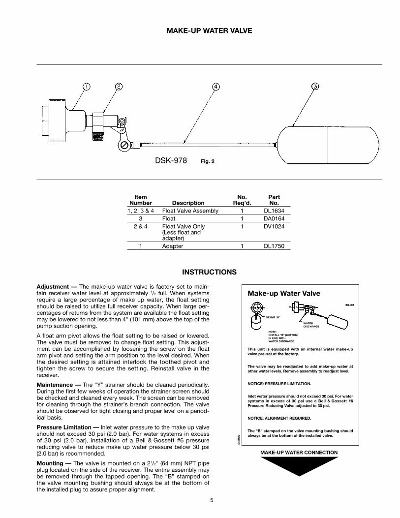
MAKE-UP WATER VALVE
INSTRUCTIONS
Item No. PartNumber Description Req’d. No.
1, 2, 3 & 4 Float Valve Assembly 1 DL16343 Float 1 DA0164
2 & 4 Float Valve Only 1 DV1024(Less float andadapter)
1 Adapter 1 DL1750
Adjustment — The make-up water valve is factory set to main-tain receiver water level at approximately 1/2 full. When systemsrequire a large percentage of make up water, the float settingshould be raised to utilize full receiver capacity. When large per-centages of returns from the system are available the float settingmay be lowered to not less than 4" (101 mm) above the top of thepump suction opening.
A float arm pivot allows the float setting to be raised or lowered.The valve must be removed to change float setting. This adjust-ment can be accomplished by loosening the screw on the floatarm pivot and setting the arm position to the level desired. Whenthe desired setting is attained interlock the toothed pivot andtighten the screw to secure the setting. Reinstall valve in thereceiver.
Maintenance — The “Y” strainer should be cleaned periodically.During the first few weeks of operation the strainer screen shouldbe checked and cleaned every week. The screen can be removedfor cleaning through the strainer’s branch connection. The valveshould be observed for tight closing and proper level on a period-ical basis.
Pressure Limitation — Inlet water pressure to the make up valveshould not exceed 30 psi (2.0 bar). For water systems in excessof 30 psi (2.0 bar), installation of a Bell & Gossett #6 pressurereducing valve to reduce make up water pressure below 30 psi(2.0 bar) is recommended.
Mounting — The valve is mounted on a 21/2" (64 mm) NPT pipeplug located on the side of the receiver. The entire assembly maybe removed through the tapped opening. The “B” stamped onthe valve mounting bushing should always be at the bottom ofthe installed plug to assure proper alignment.
Make-up Water Valve
This unit is equipped with an internal water make-upvalve pre-set at the factory.
The valve may be readjusted to add make-up water atother water levels. Remove assembly to readjust level.
NOTICE: PRESSURE LIMITATION.
Inlet water pressure should not exceed 30 psi. For watersystems in excess of 30 psi use a Bell & Gossett #6Pressure Reducing Valve adjusted to 30 psi.
NOTICE: ALIGNMENT REQUIRED.
The “B” stamped on the valve mounting bushing shouldalways be at the bottom of the installed valve.
MAKE-UP WATER CONNECTION
NOTE:INSTALL “B” (BOTTOM)IN LINE WITHWATER DISCHARGE
IDL001
DN
0122
DSK-978 Fig. 2
STAMP “B”
WATERDISCHARGE
6
These close coupled vertical centrifugal pumps are equippedwith mechanical seals. If system has not been properlycleaned prior to installation of pump, foreign matter such asdirt, pipe scale, core sand, etc. may clog the impeller anddamage the seal. A strainer is recommended in return line topump. Pump must not be operated dry. Seals may be dam-aged if operated without water present.
1. Close inlet line gate valve and operate pump momentarilyto remove as much liquid as possible from pump. Closedischarge line gate valve.
2. Shut-off and lock-out power.
3. Disconnect wiring to motor.
4. Make sure unit is cool enough that pump can be handledsafely. Open receiver drain to remove remaining liquid.
5. Loosen the four capscrews (4) holding pump case tomotor. Assure that pressure is relieved per caution note.
6. Remove four capscrews (4) holding pump case to motorand lift motor and impeller out of pump case.
7. Remove pump/motor assembly and place on work bench.
8. Prevent the motor shaft from turning by inserting a largescrewdriver into the screwdriver slot located under theplug on the rear motor endbell. Back the impeller off(counter clockwise) using a rectangular bar or other flattool inserted between the impeller vanes.
9. Remove the rotating part of the mechanical seal from theend of the shaft.
10. Remove seal holder (13) with stationary ceramic part ofmechanical seal and cup rubber from the end of the shaft.
11. Remove stationary ceramic part of mechanical seal andcup rubber from recess in seal holder.
12. To install new seal, proceed as follows: Clean recess inseal holder thoroughly. Insert new ceramic seat (groovedface first) into the rubber seat cup. Lubricate the outside ofthe cup and seal holder recess with soapy water. Installthe ceramic/cup assembly into the seal holder, makingsure the assembly bottoms evenly. When repairing "B"style pumps manufactured between 1983 through 2001,orient wire spacer eye to the left midway between motorlugs. Replace seal holder over wire spacer on the face ofthe motor, maintaining concentricity with motor face.Pumps manufactured in 2002 or later, are manufacturedwith DP1966 seal holder and do not require the wirespacer. Pumps using DP1966 should orient the seal holdertab to the left, midway between motor lugs. Using a clean,
lint-free cloth, wipe the mating surfaces of the seal cleanof any foreign matter. Moisten the carbon section of therotating part of the seal and lubricate the I.D. with soapywater. Place onto shaft to seat against the ceramic.
13. Hold motor shaft as described in #8 and replace the im-peller on the shaft (clockwise rotation) making sure it is tight.
14. Orient motor for pump reassembly with conduit opening tothe left. When mounting the pump case, discharge shouldbe 90˚ to the right of the wire spacer eye or (90˚ to the tabson DP1966) and conduit opening on motor. Use care toinsure tight gasket fit to prevent water leakage. Whenreplacing pump case, the wire spacer eye or the tabs onDP1966 should seat in pump case notch. If this does notoccur inspect for proper alignment and reassemble.
15. Replace four capscrews (4). Tighten down capscrewsevenly to avoid damage.
16. Reconnect pump bleed line (where applicable) and motorwiring.
PUMP SERVICE INSTRUCTIONS FOR WATCHMAN CENTRIFUGAL PUMPS
WARNING / HIGH VOLTAGE: Disconnect and lockout power before connecting or servicing unit.
Failure to follow these instructions could result in seriousinjury or death.
CAUTION / HOT SURFACES: Surfaces are hotwhen system is in operation. Do not touch hot re-
ceiver, let unit cool before servicing. Failure to followthese instructions could result in injury or property damage.
CAUTION / PRESSURIZED SYSTEM: Operatingsystem may contain very hot water under pressure.
Close inlet and open drains before servicing. When ser-vicing, loosen screws and move components to assurepressure is relieved before removing screws. Keep drainsopen during servicing. Failure to follow these instructionscould result in injury or property damage.
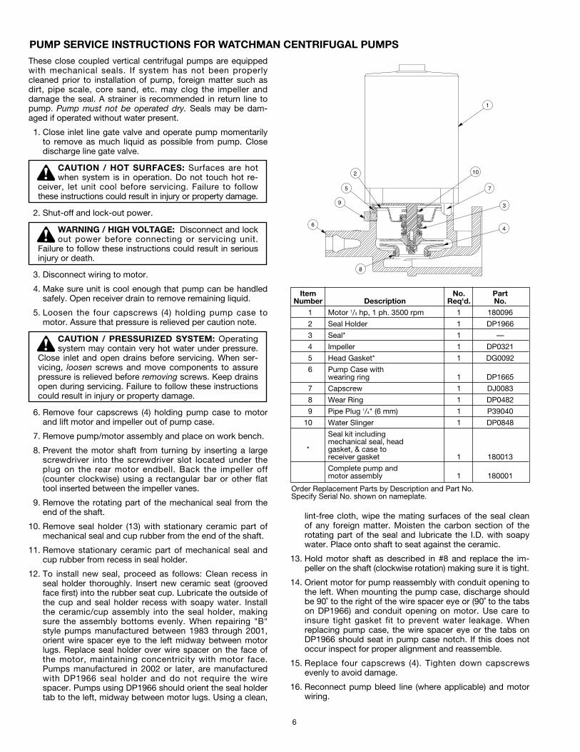
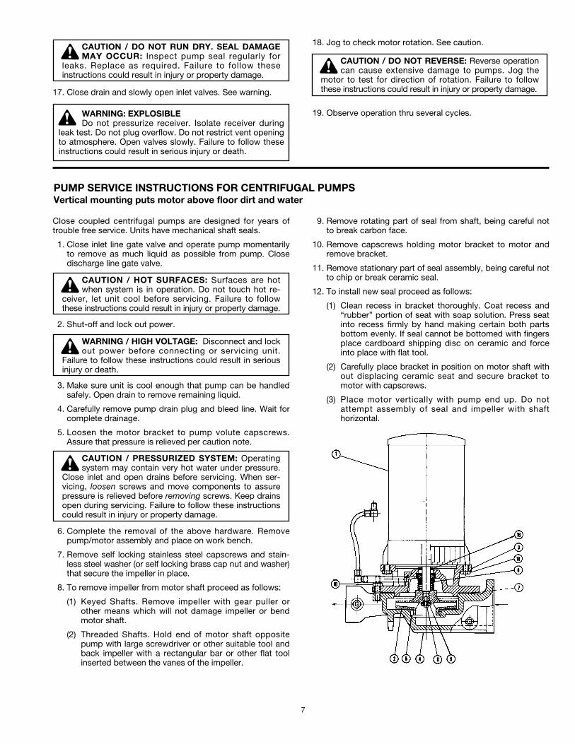
1
10
7
3
4
8
6
9
5
2
Item No. PartNumber Description Req'd. No.
1 Motor 1/3 hp, 1 ph. 3500 rpm 1 180096
2 Seal Holder 1 DP1966
3 Seal* 1 —
4 Impeller 1 DP0321
5 Head Gasket* 1 DG0092
6 Pump Case withwearing ring 1 DP1665
7 Capscrew 1 DJ0083
8 Wear Ring 1 DP0482
9 Pipe Plug 1/4" (6 mm) 1 P39040
10 Water Slinger 1 DP0848
Seal kit includingmechanical seal, head
* gasket, & case toreceiver gasket 1 180013
Complete pump andmotor assembly 1 180001
Order Replacement Parts by Description and Part No.Specify Serial No. shown on nameplate.
7
17. Close drain and slowly open inlet valves. See warning.
18. Jog to check motor rotation. See caution.
19. Observe operation thru several cycles.
Close coupled centrifugal pumps are designed for years oftrouble free service. Units have mechanical shaft seals.
1. Close inlet line gate valve and operate pump momentarilyto remove as much liquid as possible from pump. Closedischarge line gate valve.
2. Shut-off and lock out power.
3. Make sure unit is cool enough that pump can be handledsafely. Open drain to remove remaining liquid.
4. Carefully remove pump drain plug and bleed line. Wait forcomplete drainage.
5. Loosen the motor bracket to pump volute capscrews.Assure that pressure is relieved per caution note.
6. Complete the removal of the above hardware. Removepump/motor assembly and place on work bench.
7. Remove self locking stainless steel capscrews and stain-less steel washer (or self locking brass cap nut and washer)that secure the impeller in place.
8. To remove impeller from motor shaft proceed as follows:
(1) Keyed Shafts. Remove impeller with gear puller orother means which will not damage impeller or bendmotor shaft.
(2) Threaded Shafts. Hold end of motor shaft oppositepump with large screwdriver or other suitable tool andback impeller with a rectangular bar or other flat toolinserted between the vanes of the impeller.
9. Remove rotating part of seal from shaft, being careful notto break carbon face.
10. Remove capscrews holding motor bracket to motor andremove bracket.
11. Remove stationary part of seal assembly, being careful notto chip or break ceramic seal.
12. To install new seal proceed as follows:
(1) Clean recess in bracket thoroughly. Coat recess and“rubber” portion of seat with soap solution. Press seatinto recess firmly by hand making certain both partsbottom evenly. If seal cannot be bottomed with fingersplace cardboard shipping disc on ceramic and forceinto place with flat tool.
(2) Carefully place bracket in position on motor shaft without displacing ceramic seat and secure bracket tomotor with capscrews.
(3) Place motor vertically with pump end up. Do notattempt assembly of seal and impeller with shafthorizontal.
PUMP SERVICE INSTRUCTIONS FOR CENTRIFUGAL PUMPSVertical mounting puts motor above floor dirt and water
CAUTION / DO NOT RUN DRY. SEAL DAMAGEMAY OCCUR: Inspect pump seal regularly for
leaks. Replace as required. Failure to follow theseinstructions could result in injury or property damage.
WARNING / HIGH VOLTAGE: Disconnect and lockout power before connecting or servicing unit.
Failure to follow these instructions could result in seriousinjury or death.
CAUTION / HOT SURFACES: Surfaces are hotwhen system is in operation. Do not touch hot re-
ceiver, let unit cool before servicing. Failure to followthese instructions could result in injury or property damage.
CAUTION / PRESSURIZED SYSTEM: Operatingsystem may contain very hot water under pressure.
Close inlet and open drains before servicing. When ser-vicing, loosen screws and move components to assurepressure is relieved before removing screws. Keep drainsopen during servicing. Failure to follow these instructionscould result in injury or property damage.
CAUTION / DO NOT REVERSE: Reverse operationcan cause extensive damage to pumps. Jog the
motor to test for direction of rotation. Failure to followthese instructions could result in injury or property damage.
WARNING: EXPLOSIBLEDo not pressurize receiver. Isolate receiver during
leak test. Do not plug overflow. Do not restrict vent openingto atmosphere. Open valves slowly. Failure to follow theseinstructions could result in serious injury or death.
Xylem Inc.
8200 N. Austin Avenue Morton Grove, Illinois 60053 Phone: (847) 966-3700 Fax: (847) 965-8379www.xylem.com/bellgossett
Bell & Gossett is a trademark of Xylem Inc. or one of its subsidiaries. © 2019 Xylem Inc. DN0162H May 2019
(4) The carbon ring of the rotating seal part should not beloose in the seal head. If it is, apply a small amount ofgrease to the rubber bellows underneath the carbonring to hold the ring in place. Using clean, lint freecloth, wipe mating surfaces perfectly clean. Soap shaftand push seal onto shaft so that carbon will contactceramic seal. If spacer is required, use grease to causespacer to adhere to bottom of seal after seal has beenput on shaft. Be sure spacer is on larger diameter ofshaft so that it will not catch between shoulder andimpeller.
13. Replace impeller on shaft. Replace stainless steel washerand secure impeller with capscrew or cap nut.
14. Place new gasket on pump volute and reassemble motorand pump subassembly on pump volute.
15. Reconnect pump bleed line and motor wiring.
16. Close drain and slowly open inlet valves. See warning.
17. Jog to check motor rotation. See caution.
18. Observe operation thru several cycles.
Item No. PartNumber Description Req’d. No.
1 Motor — Order by Description 1 Consult Factory
2 Impeller 1 Consult Factory
3 Pump Head 1 DP0208
4 Case with Wear Ring 1 DP1603
5 Wearing Ring 1 DP0482
8 Impeller Capscrew 1 DJ0213
9 Impeller Washer 1 DJ0267
10 Capscrews 8 DJ0066
18 Water Slinger 1 DP0848
Seal Kit Including Mech6,7 Seal, Head Gasket 1 180014
Complete Pump andMotor Assembly 1 Consult Factory
Case to Rec. Gasket 1 DG0060
Order Replacement Parts by Description and Part No.Specify Serial No. shown on nameplate.
CAUTION / DO NOT RUN DRY. SEAL DAMAGEMAY OCCUR: Inspect pump seal regularly for
leaks. Replace as required. Failure to follow theseinstructions could result in injury or property damage.
CAUTION / DO NOT REVERSE: Reverse operationcan cause extensive damage to pumps. Jog the
motor to test for direction of rotation. Failure to followthese instructions could result in injury or property damage.
WARNING: EXPLOSIBLEDo not pressurize receiver. Isolate receiver during
leak test. Do not plug overflow. Do not restrict vent openingto atmosphere. Open valves slowly. Failure to follow theseinstructions could result in serious injury or death.