Embed Size (px)
Citation preview

Hocheffi zienter Wand-/DeckenverdampferHigh effi ciency unit coolers
Pulverbeschichtung
Qualitätsventilatoren
Powder coating
High quality axial fans
www.guentner.asia
GSF.3R404A, R507, R134a, R22, ...
50 Hz / 60 Hz
102.15GSF.3
2
Optimiertes Kältemittel füll volumen
Optimised refrigerant charge

Application benefits
Highly efficient heat exchanger
Tray with slope towards the drain
02.15
031031
.3
D
D
D
IGSF.3
Hocheffizienter Wärmeaustauscher
Versetzte Rohr-anordnungStaggered tube pattern
Hot air defrost on request - HHeißgasabtauung auf Wunsch

02.15GSF.3
7
GSF.3 50 Hz GSF.3 50 Hz1 Ventilator 1 FanLeistungstabellen Capacity tables
Technische Änderungen vorbehalten. Subject to technical amendments without prior notice!
402.15
Typ
Type
SC2 SC3
mm kW kW m2 m3/h m m dB(A)3m mm Ø mm Ø mm Ø mm Ø W W kW
GSF 031.3D/14 - ANW50 2.1 1.65 9.1 1670 9 18 45 16 16 - - 940 500 1.44 A
GSF 031.3F/14 - ANW50 2.8 2.1 13.6 1530 8 16 45 16 16 - - 940 500 1.44 A
GSF 031.3H/14 - ANW50 3.2 2.4 18.1 1380 8 16 45 16 16 - - 1410 500 1.91 A
GSF 040.3D/14 - ANW50 4 3 16.8 3240 11 22 52 16 18 - - 1080 700 1.78 A
GSF 040.3F/14 - ANW50 5.3 4.2 25.1 3080 11 22 52 16 22 - - 1620 700 2.32 A
GSF 040.3H/14 - ANW50 6.3 4.9 33.5 2930 11 22 52 16 22 - - 2160 700 2.86 A
GSF 031.3D/16 - ANW50 1.78 1.4 6.2 1710 9 18 45 16 16 16 12 940 500 1.44 A
GSF 031.3F/16 - ANW50 2.4 1.88 9.3 1630 8 16 45 16 16 16 12 940 500 1.44 A
GSF 031.3H/16 - ANW50 2.9 2.2 12.4 1550 8 16 45 16 16 16 12 1410 500 1.91 A
GSF 040.3D/16 - ANW50 3.3 2.6 11.4 3330 11 22 52 16 16 16 12 1080 700 1.78 A
GSF 040.3F/16 - ANW50 4.6 3.6 17.2 3220 11 22 52 16 18 16 12 1620 700 2.32 A
GSF 040.3H/16 - ANW50 5.5 4.4 22.9 3110 11 22 52 16 22 16 12 2160 700 2.86 A
GSF 031.3D/17 - ANW50 1.51 1.15 5.3 1756 9 18 45 12 12 16 12 940 500 1.44 A
GSF 031.3F/17 - ANW50 2.1 1.71 7.9 1665 9 18 45 16 18 16 12 940 500 1.44 A
GSF 031.3H/17 - ANW50 2.7 2.1 10.6 1574 8 16 45 16 18 16 12 1410 500 1.91 A
GSF 040.3D/17 - ANW50 2.8 2.2 9.8 3401 13 26 52 16 22 16 12 1080 700 1.78 A
GSF 040.3F/17 - ANW50 4 3.3 14.7 3274 13 26 52 16 28 16 12 1620 700 2.32 A
GSF 040.3H/17 - ANW50 5.1 4.1 19.6 3145 12 24 52 16 28 16 12 2160 700 2.86 A
NennleistungNominal Capacity
R404A
AnschlüsseConnections
KältemittelRefrigerant
El. Abtauheizun
Lam
elle
ntei
lung
Fin
Spac
ing
* Mehrfacheinspritzung * Multiple injection
siehe Seite 17 see page 17
Die Wurfweitenangabe stellt die Entfernung vom Gerät dar, bei der isotherm in einem idealen Raum noch eine Luftgeschwindigkeit von 0,5 m/s messbar ist. Die Ein-dringtiefe des Luftstroms in den Kühlraum ist von den örtlichen Gegebenheiten (Raumgeometrie, Einbauten, Luftabkühlung, Platzierung und Bereifung der Geräte, Beladung des Kühlraums) abhängig.
The indicated air throw represents the distance from the unit to a point where an air velocity of 0.5 m/s can still be measured isothermally in an ideal space. The penetration depth of the air flow in the cold room depends on the surrounding conditions (spatial geo-metry, installed equipment, a ir cooling, positioning of units frost formation and load in cold room).
GSF.3
4
6
El. Abtauheizung
El. DefrostD
T1 =
8K
to =
-8°C
DT1
= 7
Kto
= -
25°C
Fläc
heSu
rfac
e
luftvo
lum
enst
orm
Air
volu
me
flow
Wur
fwei
te o
hne
Stre
amer
Air
thro
w w
ithou
t St
ream
er
Wur
fwei
te m
it St
ream
erA
ir th
row
with
Str
eam
er
Scha
lldru
ckSo
und
pres
sure
Ein
Inle
t
Aus
Out
let
Hei
ßgas
Blo
ck e
inH
ot g
as c
oil i
nlet
Hei
ßgas
Wan
ne e
in /
aus
Hot
gas
tra
y in
let
/ ou
tlet
Blo
ckC
oil
Trop
fwan
neD
rip t
ray
Ges
amt
Tota
l
Ans
chlu
sssc
hem
aC
onne
ctio
n di
agra
m

GSF.3 60 Hz GSF.3 60 Hz1 Ventilator 1 FanLeistungstabellen Capacity tables
Technische Änderungen vorbehalten. Subject to technical amendments without prior notice!
502.15GSF.3
siehe Seite 17 see page 17
* Mehrfacheinspritzung * Multiple injection
Die Wurfweitenangabe stellt die Entfernung vom Gerät dar, bei der isotherm in einem idealen Raum noch eine Luftgeschwindigkeit von 0,5 m/s messbar ist. Die Ein-dringtiefe des Luftstroms in den Kühlraum ist von den örtlichen Gegebenheiten (Raumgeometrie, Einbauten, Luftabkühlung, Platzierung und Bereifung der Geräte, Beladung des Kühlraums) abhängig.
The indicated air throw represents the distance from the unit to a point where an air velocity of 0.5 m/s can still be measured isothermally in an ideal space. The penetration depth of the air flow in the cold room depends on the surrounding conditions (spatial geo-metry, installed equipment, a ir cooling, positioning of units frost formation and load in cold room).
7
Typ
Type
SC2 SC3
mm kW kW m2 m3/h m m dB(A)3m mm Ø mm Ø mm Ø mm Ø W W kW
GSF 031.3D/14 - ANX50 2.1 1.7 9.1 1800 9 19 45 16 16 - - 940 500 1.44 A
GSF 031.3F/14 - ANX50 2.8 2.2 13.6 1630 8 17 45 16 16 - - 940 500 1.44 A
GSF 031.3H/14 - ANX50 3.3 2.5 18.1 1480 8 17 45 16 16 - - 1410 500 1.91 A
GSF 040.3D/14 - ANX50 4.3 3.3 16.8 3940 11 24 52 16 18 - - 1080 700 1.78 A
GSF 040.3F/14 - ANX50 5.8 4.5 25.1 3720 11 23 52 16 22 - - 1620 700 2.32 A
GSF 040.3H/14 - ANX50 7 5.4 33.5 3520 11 23 52 16 22 - - 2160 700 2.86 A
GSF 031.3D/16 - ANX50 1.82 1.43 6.2 1850 9 19 45 16 16 16 12 940 500 1.44 A
GSF 031.3F/16 - ANX50 2.5 1.93 9.3 1740 8 17 45 16 16 16 12 940 500 1.44 A
GSF 031.3H/16 - ANX50 3 2.3 12.4 1640 8 17 45 16 16 16 12 1410 500 1.91 A
GSF 040.3D/16 - ANX50 3.5 2.8 11.4 4050 11 23 52 16 16 16 12 1080 700 1.78 A
GSF 040.3F/16 - ANX50 4.9 3.9 17.2 3890 11 23 52 16 22 16 12 1620 700 2.32 A
GSF 040.3H/16 - ANX50 6 4.8 22.9 3740 11 23 52 16 22 16 12 2160 700 2.86 A
GSF 031.3D/17 - ANX50 1.55 1.18 5.3 1918 10 20 45 12 12 16 12 940 500 1.44 A
GSF 031.3F/17 - ANX50 2.2 1.77 7.9 1794 9 19 45 16 18 16 12 940 500 1.44 A
GSF 031.3H/17 - ANX50 2.8 2.1 10.6 1677 9 19 45 16 18 16 12 1410 500 1.91 A
GSF 040.3D/17 - ANX50 2.9 2.4 9.8 4148 13 27 52 16 22 16 12 1080 700 1.78 A
GSF 040.3F/17 - ANX50 4.3 3.5 14.7 3974 13 27 52 16 28 16 12 1620 700 2.32 A
GSF 040.3H/17 - ANX50 5.5 4.4 19.6 3796 12 25 52 16 28 16 12 2160 700 2.86 A
NennleistungNominal Capacity
R404A
AnschlüsseConnections
KältemittelRefrigerant
El. Abtauheizun
Lam
elle
ntei
lung
Fin
Spac
ing
4
6
El. Abtauheizung
El. Defrost
DT1
= 8
Kto
= -
8°C
DT1
= 7
Kto
= -
25°C
Fläc
heSu
rfac
e
luftvo
lum
enst
orm
Air
volu
me
flow
Wur
fwei
te o
hne
Stre
amer
Air
thro
w w
ithou
t St
ream
er
Wur
fwei
te m
it St
ream
erA
ir th
row
with
Str
eam
er
Scha
lldru
ckSo
und
pres
sure
Ein
Inle
t
Aus
Out
let
Hei
ßgas
Blo
ck e
inH
ot g
as c
oil i
nlet
Hei
ßgas
Wan
ne e
in /
aus
Hot
gas
tra
y in
let
/ ou
tlet
Blo
ckC
oil
Trop
fwan
neD
rip t
ray
Ges
amt
Tota
l
Ans
chlu
sssc
hem
aC
onne
ctio
n di
agra
m

Technische Änderungen vorbehalten. Subject to technical amendments without prior notice!
GSF.3 50 Hz / 60 Hz GSF.3 50 Hz / 60 Hz1 Ventilator 1 FanGewicht und Maße Weights and Measures
6
Deckenaufhänger für Baugrößen 031 – 040:Ceiling hangers for sizes 031 – 040:
10,523,5
21
02.15GSF.3
Typ / Type GSF040.3.. .
KB L
F
H
A C E
Typ / Type GSF031.3…
KB
H
F A C E
L
10,5 × 16
Typ Rohrvolumen Nettogewicht
K
Ablauf
G-Gewinde
flachdichtend
Drain
G-thread flat
sealing
DIN-ISO
228-1
Type Tube volume Net weight
Abmessungen
Dimensions
GSF 031.3D/14 - AN...50 1.5 19 734 - 448 147 - 460 442 339 300 G¾GSF 031.3F/14 - AN...50 2.2 22 734 - 448 147 - 460 442 339 300 G¾GSF 031.3H/14 - AN...50 2.9 24 734 - 448 147 - 460 442 339 300 G¾GSF 040.3D/14 - AN...50 2.5 30 984 - 546 167 - 680 680 414 400 G1¼GSF 040.3F/14 - AN...50 3.7 35 984 - 546 167 - 680 680 414 400 G1¼GSF 040.3H/14 - AN...50 4.9 38 984 - 546 167 - 680 680 414 400 G1¼
GSF 031.3D/16 - AN...50 1.5 19 734 814 448 147 227 460 442 339 300 G¾GSF 031.3F/16 - AN...50 2.2 22 734 814 448 147 227 460 442 339 300 G¾GSF 031.3H/16 - AN...50 2.9 24 734 814 448 147 227 460 442 339 300 G¾GSF 040.3D/16 - AN...50 2.5 30 984 1084 546 167 267 680 680 414 400 G1¼GSF 040.3F/16 - AN...50 3.7 35 984 1084 546 167 267 680 680 414 400 G1¼GSF 040.3H/16 - AN...50 4.9 38 984 1084 546 167 267 680 680 414 400 G1¼
GSF 031.3D/17 - AN...50 2.1 21 734 814 448 147 227 460 442 339 300 G¾GSF 031.3F/17 - AN...50 3.2 24 734 814 448 147 227 460 442 339 300 G¾GSF 031.3H/17 - AN...50 4.3 28 734 814 448 147 227 460 442 339 300 G¾GSF 040.3D/17 - AN...50 3.7 33 984 1084 546 167 267 680 680 414 400 G1¼GSF 040.3F/17 - AN...50 5.6 39 984 1084 546 167 267 680 680 414 400 G1¼GSF 040.3H/17 - AN...50 7.4 43 984 1084 546 167 267 680 680 414 400 G1¼
L L B C C E H F A l kg mm mm mm mm mm mm mm mm mm NW "
With
out
hot
gas
With
hot
gas
With
out
hot
gas
With
hot
gas

Technische Änderungen vorbehalten. Subject to technical amendments without prior notice!
702.15GSF.3
GSF.3 50 Hz GSF.3 50 Hz2 Ventilatoren 2 FansLeistungstabellen Capacity tables
* Mehrfacheinspritzung * Multiple injection
siehe Seite 17 see page 17
Die Wurfweitenangabe stellt die Entfernung vom Gerät dar, bei der isotherm in einem idealen Raum noch eine Luftgeschwindigkeit von 0,5 m/s messbar ist. Die Ein-dringtiefe des Luftstroms in den Kühlraum ist von den örtlichen Gegebenheiten (Raumgeometrie, Einbauten, Luftabkühlung, Platzierung und Bereifung der Luftküh-ler, Beladung des Kühlraums) abhängig.
The indicated air throw represents the distance from the unit to a point where an air velocity of 0.5 m/s can still be measured isothermally in an ideal space. The penetration depth of the air flow in the cold room depends on the surrounding conditions (spatial geo-metry, installed equipment, a ir cooling, positioning of air coolers frost formation and load in cold room).
7
Typ
Type
SC2 SC3
mm kW kW m2 m3/h m m dB(A)3m mm Ø mm Ø mm Ø mm Ø W W kW
GSF 031.3D/24 - ANW50 4.3 3.2 18.1 3340 10 20 48 16 18 - - 1720 650 2.37 A
GSF 031.3F/24 - ANW50 5.6 4.3 27.2 3060 9 18 48 16 22 - - 1720 650 2.37 A
GSF 031.3H/24 - ANW50 6.4 4.9 36.3 2760 9 17 48 16 22 - - 2580 650 3.23 A
GSF 040.3D/24 - ANW50 7.9 6.1 33.5 6480 13 26 55 16 28 - - 2900 1200 4.1 A
GSF 040.3F/24 - ANW50 10.7 8.3 50.3 6160 12 24 55 22 28 - - 4350 1200 5.55 B
GSF 040.3H/24 - ANW50 12.7 9.9 67 5860 11 22 55 22 35 - - 5800 1200 7 B
GSF 050.3D/24 - AND50 16.7 12.3 67.4 13310 19 38 60 22 35 - - 7000 2400 9.4 B
GSF 050.3F/24 - AND50 23.2 17.4 101 12760 19 38 60 28 42 - - 7000 2400 9.4 B
GSF 050.3H/24 - AND50 27.6 20.9 134.7 12250 18 36 60 28 42 - - 8750 2400 11.15 B
GSF 031.3D/26 - ANW50 3.6 2.8 12.4 3420 10 20 48 16 16 16 12 1720 650 2.37 A
GSF 031.3F/26 - ANW50 4.8 3.8 18.6 3260 9 18 48 16 18 16 12 1720 650 2.37 A
GSF 031.3H/26 - ANW50 5.8 4.5 24.8 3100 8 16 48 16 22 16 12 2580 650 3.23 A
GSF 040.3F/26 - ANW50 9.1 7.3 34.3 6440 14 28 55 22 28 22 12 4350 1200 5.55 B
GSF 040.3H/26 - ANW50 11.1 8.9 45.8 6220 13 26 55 22 28 22 12 5800 1200 7 B
GSF 050.3F/26 - AND50 18.9 14.8 69.5 13020 19 38 60 28 35 28 22 7000 2400 9.4 B
GSF 050.3H/26 - AND50 23.3 18.2 92.6 12580 19 38 82 28 42 28 22 8750 2400 11.15 B
GSF 050.3J/26 - AND50 26.9 21.2 115.8 12170 18 36 60 28 42 28 22 10500 2400 12.9 B
GSF 031.3D/27 - ANW50 3 2.3 10.6 3512 11 22 48 16 18 16 12 1720 650 2.37 A
GSF 031.3F/27 - ANW50 4.4 3.4 15.9 3330 10 20 48 16 18 16 12 1720 650 2.37 A
GSF 031.3H/27 - ANW50 5.4 4.2 21.2 3148 9 18 48 16 22 16 12 2580 650 3.23 A
GSF 040.3F/27 - ANW50 8.3 6.5 29.4 6548 15 30 55 16 28 22 12 4350 1200 5.55 B
GSF 040.3H/27 - ANW50 10.2 8.3 39.2 6290 14 28 55 22 35 22 12 5800 1200 7 B
GSF 050.3F/27 - AND50 16.6 13.5 60.5 13190 20 40 60 28 35 28 22 8750 2400 11.15 B
GSF 050.3H/27 - AND50 20.8 16.9 80.6 12802 20 40 60 28 42 28 22 8750 2400 11.15 B
GSF 050.3J/27 - AND50 24.5 19.8 100.8 12420 19 38 60 28 42 28 22 8750 2400 11.15 B
NennleistungNominal Capacity
R404A
AnschlüsseConnections
KältemittelRefrigerant
El. Abtauheizun
Lam
elle
ntei
lung
Fin
Spac
ing
4
6
El. Abtauheizung
El. Defrost
DT1
= 8
Kto
= -
8°C
DT1
= 7
Kto
= -
25°C
Fläc
heSu
rfac
e
luftvo
lum
enst
orm
Air
volu
me
flow
Wur
fwei
te o
hne
Stre
amer
Air
thro
w w
ithou
t St
ream
er
Wur
fwei
te m
it St
ream
erA
ir th
row
with
Str
eam
er
Scha
lldru
ckSo
und
pres
sure
Ein
Inle
t
Aus
Out
let
Hei
ßgas
Blo
ck e
inH
ot g
as c
oil i
nlet
Hei
ßgas
Wan
ne e
in /
aus
Hot
gas
tra
y in
let
/ ou
tlet
Blo
ckC
oil
Trop
fwan
neD
rip t
ray
Ges
amt
Tota
l
Ans
chlu
sssc
hem
aC
onne
ctio
n di
agra
m

GSF.3 60 Hz GSF.3 60 Hz2 Ventilatoren 2 FansLeistungstabellen Capacity tables
Technische Änderungen vorbehalten. Subject to technical amendments without prior notice!
* Mehrfacheinspritzung * Multiple injection
siehe Seite 17 see page 17
Die Wurfweitenangabe stellt die Entfernung vom Gerät dar, bei der isotherm in einem idealen Raum noch eine Luftgeschwindigkeit von 0,5 m/s messbar ist. Die Ein-dringtiefe des Luftstroms in den Kühlraum ist von den örtlichen Gegebenheiten (Raumgeometrie, Einbauten, Luftabkühlung, Platzierung und Bereifung der Geräte, Beladung des Kühlraums) abhängig.
The indicated air throw represents the distance from the unit to a point where an air velocity of 0.5 m/s can still be measured isothermally in an ideal space. The penetration depth of the air flow in the cold room depends on the surrounding conditions (spatial geo-metry, installed equipment, a ir cooling, positioning of units frost formation and load in cold room).
802.15GSF.3
7
Typ
Type
SC2 SC3
mm kW kW m2 m3/h m m dB(A)3m mm Ø mm Ø mm Ø mm Ø W W kW
GSF 031.3D/24 - ANX50 4.4 3.3 18.1 3610 10 21 48 16 18 - - 1720 650 2.37 A
GSF 031.3F/24 - ANX50 5.7 4.4 27.2 3260 9 19 48 16 22 - - 1720 650 2.37 A
GSF 031.3H/24 - ANX50 6.6 5.1 36.3 2970 9 18 48 16 22 - - 2580 650 3.23 A
GSF 040.3D/24 - ANX50 8.5 6.6 33.5 7880 13 27 55 16 28 - - 2900 1200 4.1 A
GSF 040.3F/24 - ANX50 11.6 9 50.3 7440 12 25 55 22 28 - - 4350 1200 5.55 B
GSF 040.3H/24 - ANX50 14 10.9 67 7040 11 23 55 22 35 - - 5800 1200 7 B
GSF 050.3D/24 - ANI50 17.5 12.9 67.4 14940 19 38 60 22 35 - - 7000 2400 9.4 B
GSF 050.3F/24 - ANI50 24.4 18.3 101 14270 19 38 60 28 42 - - 7000 2400 9.4 B
GSF 050.3H/24 - ANI50 29.2 22.1 134.7 13670 18 36 60 28 42 - - 8750 2400 11.15 B
GSF 031.3D/26 - ANX50 3.7 2.9 12.4 3700 10 20 48 16 16 16 12 1720 650 2.37 A
GSF 031.3F/26 - ANX50 5 3.9 18.6 3480 9 18 48 16 18 16 12 1720 650 2.37 A
GSF 031.3H/26 - ANX50 5.9 4.7 24.8 3280 8 16 48 16 22 16 12 2580 650 3.23 A
GSF 040.3F/26 - ANX50 9.8 7.8 34.3 7780 14 28 55 22 28 22 12 4350 1200 5.55 B
GSF 040.3H/26 - ANX50 12.1 9.6 45.8 7480 13 26 55 22 28 22 12 5800 1200 7 B
GSF 050.3F/26 - ANI50 19.7 15 69.5 14590 19 38 60 28 35 28 22 7000 2400 9.4 B
GSF 050.3H/26 - ANI50 24.5 19.2 92.6 14050 19 38 82 28 42 28 22 8750 2400 11.15 B
GSF 050.3J/26 - ANI50 28.4 22.4 115.8 13570 18 36 60 28 42 28 22 10500 2400 12.9 B
GSF 031.3D/27 - ANX50 3.1 2.4 10.6 3837 11 22 48 16 18 16 12 1720 650 2.37 A
GSF 031.3F/27 - ANX50 4.5 3.5 15.9 3587 10 21 48 16 18 16 12 1720 650 2.37 A
GSF 031.3H/27 - ANX50 5.6 4.3 21.2 3355 9 19 48 16 22 16 12 2580 650 3.23 A
GSF 040.3F/27 - ANX50 8.8 6.9 29.4 7948 15 31 55 16 28 22 12 4350 1200 5.55 B
GSF 040.3H/27 - ANX50 11 9 39.2 7592 14 29 55 22 35 22 12 5800 1200 7 B
GSF 050.3F/27 - ANI50 17.4 14.1 60.5 14790 20 41 61 28 35 28 22 8750 2400 11.15 B
GSF 050.3H/27 - ANI50 21.9 17.7 80.6 14300 20 41 61 28 42 28 22 8750 2400 11.15 B
GSF 050.3J/27 - ANI50 25.8 20.8 100.8 13850 19 39 61 28 42 28 22 8750 2400 11.15 B
NennleistungNominal Capacity
R404A
AnschlüsseConnections
KältemittelRefrigerant
El. Abtauheizun
Lam
elle
ntei
lung
Fin
Spac
ing
4
6
El. Abtauheizung
El. DefrostD
T1 =
8K
to =
-8°C
DT1
= 7
Kto
= -
25°C
Fläc
heSu
rfac
e
luftvo
lum
enst
orm
Air
volu
me
flow
Wur
fwei
te o
hne
Stre
amer
Air
thro
w w
ithou
t St
ream
er
Wur
fwei
te m
it St
ream
erA
ir th
row
with
Str
eam
er
Scha
lldru
ckSo
und
pres
sure
Ein
Inle
t
Aus
Out
let
Hei
ßgas
Blo
ck e
inH
ot g
as c
oil i
nlet
Hei
ßgas
Wan
ne e
in /
aus
Hot
gas
tra
y in
let
/ ou
tlet
Blo
ckC
oil
Trop
fwan
neD
rip t
ray
Ges
amt
Tota
l
Ans
chlu
sssc
hem
aC
onne
ctio
n di
agra
m

Technische Änderungen vorbehalten. Subject to technical amendments without prior notice!
902.15
GSF.3 50 Hz / 60 Hz GSF.3 50 Hz / 60 Hz2 Ventilatoren 2 FansGewicht und Maße Weights and Measures
Deckenaufhänger für Baugrößen 031 – 050:Ceiling hangers for sizes 031 – 050:
21
10,523,5
GSF.3
Typ / Type GSF040.3.. . GSF050.3.. .
KB L
F
H
A C E
Abmessungen
Dimensions
GSF 031.3D/24 - AN...50 2.5 32 1194 - 448 147 - 920 442 339 300 G¾GSF 031.3F/24 - AN...50 3.8 36 1194 - 448 147 - 920 442 339 300 G¾GSF 031.3H/24 - AN...50 5 40 1194 - 448 147 - 920 442 339 300 G¾GSF 040.3D/24 - AN...50 4.4 51 1714 1814 546 217 317 1360 542 414 400 G1¼GSF 040.3F/24 - AN...50 6.6 59 1714 1814 546 217 317 1360 542 414 400 G1¼GSF 040.3H/24 - AN...50 8.8 66 1714 1814 546 217 317 1360 542 414 400 G1¼GSF 050.3D/24 - AN...50 13.4 101 2402 2522 635 272 392 2000 742 494 550 G1¼GSF 050.3F/24 - AN...50 20.8 118 2402 2522 635 272 392 2000 742 494 550 G1¼GSF 050.3H/24 - AN...50 26.6 136 2402 2522 635 272 392 2000 742 494 550 G1¼
GSF 031.3D/26 - AN...50 2.5 33 1194 1274 448 147 227 920 442 339 300 G¾GSF 031.3F/26 - AN...50 3.7 36 1194 1274 448 147 227 920 442 339 300 G¾GSF 031.3H/26 - AN...50 5 40 1194 1274 448 147 227 920 442 339 300 G¾GSF 040.3F/26 - AN...50 6.6 59 1714 1814 546 217 317 1360 542 414 400 G1¼GSF 040.3H/26 - AN...50 8.8 67 1714 1814 546 217 317 1360 542 414 400 G1¼GSF 050.3F/26 - AN...50 20.6 121 2402 2522 635 272 392 2000 742 494 550 G1¼GSF 050.3H/26 - AN...50 26.6 139 2402 2522 635 272 392 2000 742 494 550 G1¼GSF 050.3J/26 - AN...50 33.8 157 2402 2522 635 272 392 2000 742 494 550 G1¼
GSF 031.3D/27 - AN...50 3.8 33 1194 1274 448 147 227 920 442 339 300 G¾GSF 031.3F/27 - AN...50 5.7 37 1194 1274 448 147 227 920 442 339 300 G¾GSF 031.3H/27 - AN...50 7.5 44 1194 1274 448 147 227 920 442 339 300 G¾GSF 040.3F/27 - AN...50 10.1 62 1714 1814 546 217 317 1360 542 414 400 G1¼GSF 040.3H/27 - AN...50 13.5 75 1714 1814 546 217 317 1360 542 414 400 G1¼GSF 050.3F/27 - AN...50 20.3 118 2402 2522 635 272 392 2000 742 494 550 G1¼GSF 050.3H/27 - AN...50 26.1 135 2402 2522 635 272 392 2000 742 494 550 G1¼GSF 050.3J/27 - AN...50 33.2 151 2402 2522 635 272 392 2000 742 494 550 G1¼
Typ Rohrvolumen Nettogewicht
K
AblaufG-Gewinde
flachdichtend
DrainG-thread flat
sealingDIN-ISO228-1 L L B C C E H F A
l kg mm mm mm mm mm mm mm mm mm NW "
With
out
hot
gas
With
hot
gas
With
out
hot
gas
With
hot
gas
Type Tube volume Net weight
Typ / Type GSF031.3…
10,5 × 16
KB
H
F A C E
L

Technische Änderungen vorbehalten. Subject to technical amendments without prior notice!
1002.15
GSF.3 50 Hz GSF.3 50 Hz3 Ventilatoren 3 FansLeistungstabellen Capacity tables
GSF.3
* Mehrfacheinspritzung * Multiple injection
siehe Seite 17 see page 17
Die Wurfweitenangabe stellt die Entfernung vom Gerät dar, bei der isotherm in einem idealen Raum noch eine Luftgeschwindigkeit von 0,5 m/s messbar ist. Die Ein-dringtiefe des Luftstroms in den Kühlraum ist von den örtlichen Gegebenheiten (Raumgeometrie, Einbauten, Luftabkühlung, Platzierung und Bereifung der Luftküh-ler, Beladung des Kühlraums) abhängig.
The indicated air throw represents the distance from the unit to a point where an air velocity of 0.5 m/s can still be measured isothermally in an ideal space. The penetration depth of the air flow in the cold room depends on the surrounding conditions (spatial geo-metry, installed equipment, a ir cooling, positioning of air coolers frost formation and load in cold room).
7
Typ
Type
SC2 SC3
mm kW kW m2 m3/h m m dB(A)3m mm Ø mm Ø mm Ø mm Ø W W kW
GSF 031.3F/34 - ANW50 8.4 6.3 40.8 4600 10 20 49 16 28 - - 2900 1200 4.1 A
GSF 031.3H/34 - ANW50 9.6 6.9 54.4 4150 9 18 49 16 28 - - 4350 1200 5.55 A
GSF 040.3F/34 - ANW50 16.2 12.2 75.4 9240 13 26 57 22 35 - - 4800 1200 6 A
GSF 040.3H/34 - ANW50 19.2 14.7 100.5 8790 12 24 57 22 35 - - 6400 1200 7.6 A
GSF 050.3F/34 - AND50 34.8 26.2 151.6 19140 19 38 61 28 54 - - 9600 3200 12.8 B
GSF 050.3H/34 - AND50 41.7 31.7 202.1 18380 18 36 61 35 54 - - 12000 3200 15.2 B
GSF 031.3F/36 - ANW50 7.3 5.7 27.9 4890 10 20 49 16 22 16 12 2900 1200 4.1 A
GSF 031.3H/36 - ANW50 8.7 6.9 37.1 4650 9 18 49 22 28 22 12 4350 1200 5.55 A
GSF 040.3F/36 - ANW50 13.8 10.8 51.5 9660 15 30 57 22 35 22 12 4800 1200 6 A
GSF 040.3H/36 - ANW50 16.7 13.1 68.6 9330 14 28 57 22 35 22 12 6400 1200 7.6 A
GSF 050.3H/36 - AND50 35.2 27.6 138.9 18870 21 42 61 35 54 35 22 12000 3200 15.2 B
GSF 050.3J/36 - AND50 40.5 31.9 173.6 18260 20 40 61 35 54 35 22 14400 3200 17.6 B
GSF 031.3F/37 - ANW50 6.6 4.9 23.8 4995 11 22 49 16 22 16 12 2900 1200 4.1 A
GSF 031.3H/37 - ANW50 8.3 6.7 31.8 4722 10 20 49 16 35 22 12 4350 1200 5.55 A
GSF 040.3F/37 - ANW50 12.3 9.9 44.1 9822 16 32 57 22 35 22 12 4800 1200 6 A
GSF 040.3H/37 - ANW50 15.6 11.9 58.7 9435 15 30 57 22 35 22 12 6400 1200 7.6 A
GSF 050.3H/37 - AND50 31.4 25.5 120.9 19200 22 44 61 35 54 35 22 12000 3200 15.2 B
GSF 050.3J/37 - AND50 36.8 29.7 151.2 18630 21 42 61 42 54 42 22 14400 3200 17.6 B
NennleistungNominal Capacity
R404A
AnschlüsseConnections
KältemittelRefrigerant
El. Abtauheizun
Lam
elle
ntei
lung
Fin
Spac
ing
4
6
El. Abtauheizung
El. DefrostD
T1 =
8K
to =
-8°C
DT1
= 7
Kto
= -
25°C
Fläc
heSu
rfac
e
luftvo
lum
enst
orm
Air
volu
me
flow
Wur
fwei
te o
hne
Stre
amer
Air
thro
w w
ithou
t St
ream
er
Wur
fwei
te m
it St
ream
erA
ir th
row
with
Str
eam
er
Scha
lldru
ckSo
und
pres
sure
Ein
Inle
t
Aus
Out
let
Hei
ßgas
Blo
ck e
inH
ot g
as c
oil i
nlet
Hei
ßgas
Wan
ne e
in /
aus
Hot
gas
tra
y in
let
/ ou
tlet
Blo
ckC
oil
Trop
fwan
neD
rip t
ray
Ges
amt
Tota
l
Ans
chlu
sssc
hem
aC
onne
ctio
n di
agra
m

GSF.3 60 Hz GSF.3 60 Hz3 Ventilatoren 3 FansLeistungstabellen Capacity tables
Technische Änderungen vorbehalten. Subject to technical amendments without prior notice!
Die Wurfweitenangabe stellt die Entfernung vom Gerät dar, bei der isotherm in einem idealen Raum noch eine Luftgeschwindigkeit von 0,5 m/s messbar ist. Die Ein-dringtiefe des Luftstroms in den Kühlraum ist von den örtlichen Gegebenheiten (Raumgeometrie, Einbauten, Luftabkühlung, Platzierung und Bereifung der Geräte, Beladung des Kühlraums) abhängig.
The indicated air throw represents the distance from the unit to a point where an air velocity of 0.5 m/s can still be measured isothermally in an ideal space. The penetration depth of the air flow in the cold room depends on the surrounding conditions (spatial geo-metry, installed equipment, a ir cooling, positioning of units frost formation and load in cold room).
1102.15GSF.3
* Mehrfacheinspritzung * Multiple injection
siehe Seite 17 see page 17
7
Typ
Type
SC2 SC3
mm kW kW m2 m3/h m m dB(A)3m mm Ø mm Ø mm Ø mm Ø W W kW
GSF 031.3F/34 - ANX50 8.7 6.5 40.8 4890 11 22 50 16 28 - - 2900 1200 4.1 A
GSF 031.3H/34 - ANX50 10 7.1 54.4 4450 10 20 50 16 28 - - 4350 1200 5.55 B
GSF 040.3F/34 - ANX50 17.7 13.2 75.4 11160 14 28 58 22 35 - - 4800 1200 6 B
GSF 040.3H/34 - ANX50 21.2 16.1 100.5 10560 13 26 58 22 35 - - 6400 1200 7.6 B
GSF 050.3F/34 - ANI50 36.6 27.5 151.6 21400 20 40 62 28 54 - - 9600 3200 12.8 B
GSF 050.3H/34 - ANI50 44.2 33.5 202.1 20510 19 38 62 35 54 - - 12000 3200 15.2 B
GSF 031.3F/36 - ANX50 7.5 5.8 27.9 5220 10 20 50 16 22 16 12 2900 1200 4.1 A
GSF 031.3H/36 - ANX50 9 7.1 37.1 4920 9 18 50 22 28 22 12 4350 1200 5.55 B
GSF 040.3F/36 - ANX50 14.8 11.6 51.5 11670 15 30 58 22 35 22 12 4800 1200 6 B
GSF 040.3H/36 - ANX50 18.2 14.3 68.6 11220 14 28 58 22 35 22 12 6400 1200 7.6 B
GSF 050.3H/36 - ANI50 36.9 29 138.9 21080 21 42 62 35 54 35 22 12000 3200 15.2 B
GSF 050.3J/36 - ANI50 42.7 33.7 173.6 20360 20 40 62 35 54 35 22 14400 3200 17.6 B
GSF 031.3F/37 - ANX50 6.7 5.1 23.8 5381 11 22 50 16 22 16 12 2900 1200 4.1 A
GSF 031.3H/37 - ANX50 8 6.5 31.8 5032 10 20 50 16 35 22 12 4350 1200 5.55 B
GSF 040.3F/37 - ANX50 13.2 10.6 44.1 11922 16 32 58 22 35 22 12 4800 1200 6 B
GSF 040.3H/37 - ANX50 16.7 12.6 58.7 11388 15 31 58 22 35 22 12 6400 1200 7.6 B
GSF 050.3H/37 - ANI50 33 26.7 120.9 21460 22 44 62 35 54 35 22 12000 3200 15.2 B
GSF 050.3J/37 - ANI50 38.7 31.4 151.2 20780 21 42 62 42 54 42 22 14400 3200 17.6 B
NennleistungNominal Capacity
R404A
AnschlüsseConnections
KältemittelRefrigerant
El. Abtauheizun
Lam
elle
ntei
lung
Fin
Spac
ing
4
6
El. Abtauheizung
El. Defrost
DT1
= 8
Kto
= -
8°C
DT1
= 7
Kto
= -
25°C
Fläc
heSu
rfac
e
luftvo
lum
enst
orm
Air
volu
me
flow
Wur
fwei
te o
hne
Stre
amer
Air
thro
w w
ithou
t St
ream
er
Wur
fwei
te m
it St
ream
erA
ir th
row
with
Str
eam
er
Scha
lldru
ckSo
und
pres
sure
Ein
Inle
t
Aus
Out
let
Hei
ßgas
Blo
ck e
inH
ot g
as c
oil i
nlet
Hei
ßgas
Wan
ne e
in /
aus
Hot
gas
tra
y in
let
/ ou
tlet
Blo
ckC
oil
Trop
fwan
neD
rip t
ray
Ges
amt
Tota
l
Ans
chlu
sssc
hem
aC
onne
ctio
n di
agra
m

GSF.3 50 Hz / 60 Hz GSF.3 50 Hz / 60 Hz3 Ventilatoren 3 FansGewicht und Maße Weights and Measures
Technische Änderungen vorbehalten. Subject to technical amendments without prior notice!
1202.15GSF.3
Typ / Type GSF040.3...
B
F
H
A
KL
C E
Deckenaufhänger für Baugrößen 031 – 050:Ceiling hangers for sizes 031 – 050:
21
10,523,5
Abmessungen
Dimensions
GSF 031.3F/34 - ANW50 5.4 50 1654 - 448 147 - 442 442 339 300 G¾GSF 031.3H/34 - ANW50 7.1 56 1654 - 448 147 - 442 442 339 300 G¾GSF 040.3F/34 - ANW50 9.6 85 2394 2494 546 217 317 542 542 414 400 G1¼GSF 040.3H/34 - ANW50 12.7 95 2394 2494 546 217 317 542 542 414 400 G1¼GSF 050.3F/34 - AND50 30.5 170 3402 3522 635 272 392 742 742 494 550 G1¼GSF 050.3H/34 - AND50 40.4 197 3402 3522 635 272 392 742 742 494 550 G1¼
GSF 031.3F/36 - ANW50 5.3 51 1654 1734 448 147 227 442 442 339 300 G¾GSF 031.3H/36 - ANW50 7.1 57 1654 1734 448 147 227 442 442 339 300 G¾GSF 040.3F/36 - ANW50 9.6 86 2394 2494 546 217 317 542 542 414 400 G1¼GSF 040.3H/36 - ANW50 12.7 97 2394 2494 546 217 317 542 542 414 400 G1¼GSF 050.3H/36 - AND50 40.3 200 3402 3522 635 272 392 742 742 494 550 G1¼GSF 050.3J/36 - AND50 50.2 228 3402 3522 635 272 392 742 742 494 550 G1¼
GSF 031.3F/37 - ANW50 8.1 53 1654 1734 448 147 227 442 442 339 300 G¾GSF 031.3H/37 - ANW50 11 64 1654 1734 448 147 227 442 442 339 300 G¾GSF 040.3F/37 - ANW50 14.8 89 2394 2494 546 217 317 542 542 414 400 G1¼GSF 040.3H/37 - ANW50 19.6 107 2394 2494 546 217 317 542 542 414 400 G1¼GSF 050.3H/37 - AND50 39.9 193 3402 3522 635 272 392 742 742 494 550 G1¼GSF 050.3J/37 - AND50 49.8 220 3402 3522 635 272 392 742 742 494 550 G1¼
Typ Rohrvolumen Nettogewicht
K
Ablauf
G-Gewinde
flachdichtend
Drain
G-thread flat
sealing
DIN-ISO
228-1Type Tube volume Net weight L L B C C E H F A
l kg mm mm mm mm mm mm mm mm mm NW "
With
out
hot
gas
With
hot
gas
With
out
hot
gas
With
hot
gas
GSF050.3...
KB L
F
H
A C E E E Typ / Type
Typ / Type GSF031.3…
KB
H
F A C
E
L
E
10,5 × 16
Technische Änderungen vorbehalten. Subject to technical amendments without prior notice!
1302.15
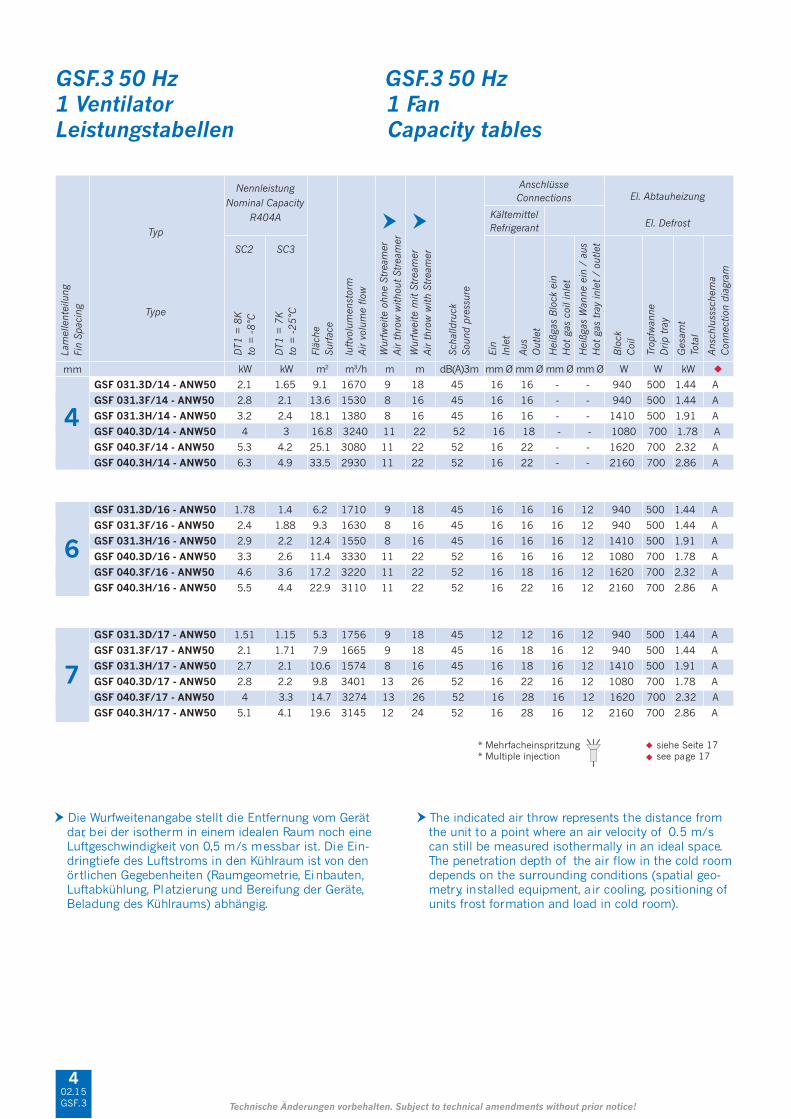
GSF.3 50 Hz GSF.3 50 Hz4 Ventilatoren 4 FansLeistungstabellen Capacity tables
Die Wurfweitenangabe stellt die Entfernung vom Gerät dar, bei der isotherm in einem idealen Raum noch eine Luftgeschwindigkeit von 0,5 m/s messbar ist. Die Ein-dringtiefe des Luftstroms in den Kühlraum ist von den örtlichen Gegebenheiten (Raumgeometrie, Einbauten, Luftabkühlung, Platzierung und Bereifung der Luftküh-ler, Beladung des Kühlraums) abhängig.
The indicated air throw represents the distance from the unit to a point where an air velocity of 0.5 m/s can still be measured isothermally in an ideal space. The penetration depth of the air flow in the cold room depends on the surrounding conditions (spatial geo-metry, installed equipment, a ir cooling, positioning of air coolers frost formation and load in cold room).
GSF.3
* Mehrfacheinspritzung * Multiple injection
siehe Seite 17 see page 17
7
Typ
Type
SC2 SC3
mm kW kW m2 m3/h m m dB(A)3m mm Ø mm Ø mm Ø mm Ø W W kW
GSF 031.3F/44 - ANW50 11.2 8.6 54.4 6130 11 22 51 22 35 - - 4000 1150 5.15 B
GSF 031.3H/44 - ANW50 12.8 9.9 72.5 5530 10 20 51 22 35 - - 6000 1150 7.15 B
GSF 040.3F/44 - ANW50 21.3 14.9 100.5 12320 14 28 59 28 42 - - 6900 2200 9.1 B
GSF 040.3H/44 - ANW50 25.6 18.3 134 11720 13 26 59 28 42 - - 9200 2200 11.4 B
GSF 050.3F/44 - AND50 45.4 31.8 202.1 25520 20 40 63 28 54 - - 14000 3600 17.6 B
GSF 050.3H/44 - AND50 55 39.2 269.4 24510 20 40 63 35 54 - - 17500 3600 21.1 B
GSF 031.3F/46 - ANW50 9.7 7.6 37.1 6520 10 20 51 22 28 22 12 4000 1150 5.15 B
GSF 031.3H/46 - ANW50 11.6 9.1 49.5 6200 9 18 51 22 28 22 12 6000 1150 7.15 B
GSF 040.3F/46 - ANW50 18.3 13.5 68.6 12880 15 30 59 22 42 22 12 6900 2200 9.1 B
GSF 040.3H/46 - ANW50 22.4 16.7 91.5 12440 14 28 59 22 42 22 12 9200 2200 11.4 B
GSF 050.3H/46 - AND50 47 35.1 185.2 25160 21 42 63 42 54 42 22 17500 3600 21.1 B
GSF 050.3J/46 - AND50 54.3 40.8 231.5 24350 20 40 63 42 64 42 22 21000 3600 24.6 B
GSF 031.3F/47 - ANW50 8.8 6.8 31.8 6660 11 22 51 16 28 22 12 4000 1150 5.15 B
GSF 031.3H/47 - ANW50 10.9 8.5 42.4 6297 10 20 51 16 35 22 12 6000 1150 7.15 B
GSF 040.3F/47 - ANW50 16.3 13.2 58.7 13097 16 32 59 22 42 22 12 6900 2200 9.1 B
GSF 040.3H/47 - ANW50 20.5 16.5 78.3 12580 15 30 59 22 54 22 12 9200 2200 11.4 B
GSF 050.3H/47 - AND50 42.7 32.8 161.3 25603 22 44 63 35 54 42 22 17500 3600 21.1 B
GSF 050.3J/47 - AND50 50 38.4 201.6 24849 21 42 63 42 64 42 22 21000 3600 24.6 B
NennleistungNominal Capacity
R404A
AnschlüsseConnections
KältemittelRefrigerant
El. Abtauheizun
Lam
elle
ntei
lung
Fin
Spac
ing
4
6
El. Abtauheizung
El. Defrost
DT1
= 8
Kto
= -
8°C
DT1
= 7
Kto
= -
25°C
Fläc
heSu
rfac
e
luftvo
lum
enst
orm
Air
volu
me
flow
Wur
fwei
te o
hne
Stre
amer
Air
thro
w w
ithou
t St
ream
er
Wur
fwei
te m
it St
ream
erA
ir th
row
with
Str
eam
er
Scha
lldru
ckSo
und
pres
sure
Ein
Inle
t
Aus
Out
let
Hei
ßgas
Blo
ck e
inH
ot g
as c
oil i
nlet
Hei
ßgas
Wan
ne e
in /
aus
Hot
gas
tra
y in
let
/ ou
tlet
Blo
ckC
oil
Trop
fwan
neD
rip t
ray
Ges
amt
Tota
l
Ans
chlu
sssc
hem
aC
onne
ctio
n di
agra
m

GSF.3 60 Hz GSF.3 60 Hz4 Ventilatoren 4 FansLeistungstabellen Capacity tables
Technische Änderungen vorbehalten. Subject to technical amendments without prior notice!
* Mehrfacheinspritzung * Multiple injection
siehe Seite 17 see page 17
Die Wurfweitenangabe stellt die Entfernung vom Gerät dar, bei der isotherm in einem idealen Raum noch eine Luftgeschwindigkeit von 0,5 m/s messbar ist. Die Ein-dringtiefe des Luftstroms in den Kühlraum ist von den örtlichen Gegebenheiten (Raumgeometrie, Einbauten, Luftabkühlung, Platzierung und Bereifung der Geräte, Beladung des Kühlraums) abhängig.
The indicated air throw represents the distance from the unit to a point where an air velocity of 0.5 m/s can still be measured isothermally in an ideal space. The penetration depth of the air flow in the cold room depends on the surrounding conditions (spatial geo-metry, installed equipment, a ir cooling, positioning of units frost formation and load in cold room).
1402.15GSF.3
7
Typ
Type
SC2 SC3
mm kW kW m2 m3/h m m dB(A)3m mm Ø mm Ø mm Ø mm Ø W W kW
GSF 031.3F/44 - ANX50 11.5 8.8 54.4 6520 11 23 52 22 35 - - 4000 1150 5.15 B
GSF 031.3H/44 - ANX50 13.3 10.3 72.5 5940 10 21 52 22 35 - - 6000 1150 7.15 B
GSF 040.3F/44 - ANX50 22.8 15.7 100.5 14880 15 30 60 22 42 - - 6900 2200 9.1 B
GSF 040.3H/44 - ANX50 27.8 19.6 134 14080 14 28 60 22 42 - - 9200 2200 11.4 B
GSF 050.3F/44 - ANI50 47.3 32.9 202.1 28540 21 42 64 28 54 - - 14000 3600 17.6 B
GSF 050.3H/44 - ANI50 57.8 40.9 269.4 27340 20 41 64 35 54 - - 17500 3600 21.1 B
GSF 031.3F/46 - ANX50 9.9 7.8 37.1 6960 10 20 52 22 28 22 12 4000 1150 5.15 B
GSF 031.3H/46 - ANX50 11.6 9.1 49.5 6200 9 18 52 22 28 22 12 6000 1150 7.15 B
GSF 040.3F/46 - ANX50 19.4 14.2 68.6 15560 15 30 60 22 42 22 12 6900 2200 9.1 B
GSF 040.3H/46 - ANX50 24.1 17.8 91.5 14960 14 28 60 22 42 22 12 9200 2200 11.4 B
GSF 050.3H/46 - ANI50 49 36.4 185.2 28110 21 42 64 35 54 35 22 17500 3600 21.1 B
GSF 050.3J/46 - ANI50 57 42.6 231.5 27150 20 40 64 42 54 42 22 21000 3600 24.6 B
GSF 031.3F/47 - ANX50 9 7 31.8 7174 12 24 52 16 28 22 12 4000 1150 5.15 B
GSF 031.3H/47 - ANX50 11.2 8.7 42.4 6709 11 22 52 16 35 22 12 6000 1150 7.15 B
GSF 040.3F/47 - ANX50 17.5 14.2 58.7 15896 17 34 60 22 42 22 12 6900 2200 9.1 B
GSF 040.3H/47 - ANX50 22.1 18 78.3 15184 16 32 60 22 54 22 12 9200 2200 11.4 B
GSF 050.3H/47 - ANI50 44.4 34.1 161.3 28610 23 46 64 35 54 35 22 17500 3600 21.1 B
GSF 050.3J/47 - ANI50 52.1 40.1 201.6 27710 22 44 63 42 64 42 22 21000 3600 24.6 B
NennleistungNominal Capacity
R404A
AnschlüsseConnections
KältemittelRefrigerant
El. Abtauheizun
Lam
elle
ntei
lung
Fin
Spac
ing
4
6
El. Abtauheizung
El. DefrostD
T1 =
8K
to =
-8°C
DT1
= 7
Kto
= -
25°C
Fläc
heSu
rfac
e
luftvo
lum
enst
orm
Air
volu
me
flow
Wur
fwei
te o
hne
Stre
amer
Air
thro
w w
ithou
t St
ream
er
Wur
fwei
te m
it St
ream
erA
ir th
row
with
Str
eam
er
Scha
lldru
ckSo
und
pres
sure
Ein
Inle
t
Aus
Out
let
Hei
ßgas
Blo
ck e
inH
ot g
as c
oil i
nlet
Hei
ßgas
Wan
ne e
in /
aus
Hot
gas
tra
y in
let
/ ou
tlet
Blo
ckC
oil
Trop
fwan
neD
rip t
ray
Ges
amt
Tota
l
Ans
chlu
sssc
hem
aC
onne
ctio
n di
agra
m

Technische Änderungen vorbehalten. Subject to technical amendments without prior notice!
1502.15GSF.3
Typ Rohrvolumen Nettogewicht
K
Ablauf
G-Gewinde
flachdichtend
Drain
G-thread flat
sealing
DIN-ISO
228-1
Type Tube volume Net weight
l kg
L L B C C E H F A
mm mm mm mm mm mm mm mm mm NW "
Abmessungen
Dimensions
GSF.3 50 Hz / 60 Hz GSF.3 50 Hz / 60 Hz4 Ventilatoren 4 FansGewicht und Maße Weights and Measures
Typ / Type GSF031.3…
Typ / Type GSF040.3... GSF050.3...
Deckenaufhänger für Baugrößen 031 – 050:Ceiling hangers for sizes 031 – 050:
21
10,523,5
KB
H
F A C
L
E E
KB L
F
H
A C E E
10,5 × 16
GSF 031.3F/44 - ANW50 7 75 2114 - 448 147 - 920 442 339 339 G¾
GSF 031.3H/44 - ANW50 9.2 86 2114 - 448 147 - 920 442 339 339 G¾
GSF 040.3F/44 - ANW50 12.7 122 3074 3174 546 217 317 1360 542 414 414 G1¼
GSF 040.3H/44 - ANW50 16.8 141 3074 3174 546 217 317 1360 542 414 414 G1¼
GSF 050.3F/44 - AND50 39.7 224 4402 4522 635 272 392 2000 742 494 550 G1¼
GSF 050.3H/44 - AND50 52.7 258 4402 4522 635 272 392 2000 742 494 550 G1¼
GSF 031.3F/46 - ANW50 6.9 68 2114 2194 448 147 227 920 442 339 339 G¾
GSF 031.3H/46 - ANW50 9.2 85 2114 2194 448 147 227 920 442 339 339 G¾
GSF 040.3F/46 - ANW50 12.6 114 3074 3174 546 217 317 1360 542 414 414 G1¼
GSF 040.3H/46 - ANW50 16.7 138 3074 3174 546 217 317 1360 542 414 414 G1¼
GSF 050.3H/46 - AND50 52.8 264 4402 4522 635 272 392 2000 742 494 550 G1¼
GSF 050.3J/46 - AND50 54.3 299 4402 4522 635 272 392 2000 742 494 550 G1¼
GSF 031.3F/47 - ANW50 10.6 69 2114 2194 448 147 227 920 442 339 339 G¾
GSF 031.3H/47 - ANW50 14.2 83 2114 2194 448 147 227 920 442 339 339 G¾
GSF 040.3F/47 - ANW50 19.5 116 3074 3174 546 217 317 1360 542 414 414 G1¼
GSF 040.3H/47 - ANW50 26 141 3074 3174 546 217 317 1360 542 414 414 G1¼
GSF 050.3H/47 - AND50 52.4 255 4402 4522 635 272 392 2000 742 494 550 G1¼
GSF 050.3J/47 - AND50 52.9 288 4402 4522 635 272 392 2000 742 494 550 G1¼
With
out
hot
gas
With
hot
gas
With
out
hot
gas
With
hot
gas

Technische Änderungen vorbehalten. Subject to technical amendments without prior notice!
1602.15GSF.3
GSF.3 GSF.3Daten je Ventilator Data per fan
mögliches Ventilator-Anschlussschema für Verdrahtung durch Kunden siehe Seite 17
see page 17
possible fan wiring diagram for wired by customer, see page 17 see page 17
Typ Motor Stromart Typ Motor Stromart
Type
Type of motor current
50 Hz Type
Type of motor current
60 Hz
W A dB(A) W A dB(A)
031.3D/...4 - ANW50 90 0,41 66 D1 031.3D/...4 - ANX50 140 0,61 67 D1
031.3F/...4 - ANW50 90 0,41 66 D1 031.3F/...4 - ANX50 140 0,61 67 D1
031.3H/...4 - ANW50 90 0,41 66 D1 031.3H/...4 - ANX50 140 0,61 67 D1
040.3D/...4 - ANW50 225 1,05 74 E1 040.3D/...4 - ANX50 320 1,38 75 E1
040.3F/...4 - ANW50 225 1,05 74 E1 040.3F/...4 - ANX50 320 1,38 75 E1
040.3H/...4 - ANW50 225 1,05 74 E1 040.3H/...4 - ANX50 320 1,38 75 E1
050.3D/...4 - AND50 690 1,55 80 J1 050.3D/...4 - ANI50 1000 1,85 83 J1
050.3F/...4 - AND50 690 1,55 80 J1 050.3F/...4 - ANI50 1000 1,85 83 J1
050.3H/...4 - AND50 690 1,55 80 J1 050.3H/...4 - ANI50 1000 1,85 83 J1
031.3D/...6 - ANW50 90 0,41 66 D1 031.3D/...6 - ANX50 140 0,61 67 D1
031.3F/...6 - ANW50 90 0,41 66 D1 031.3F/...6 - ANX50 140 0,61 67 D1
031.3H/...6 - ANW50 90 0,41 66 D1 031.3H/...6 - ANX50 140 0,61 67 D1
040.3D/...6 - ANW50 225 1,05 74 E1 040.3D/...6 - ANX50 320 1,38 75 E1
040.3F/...6 - ANW50 225 1,05 74 E1 040.3F/...6 - ANX50 320 1,38 75 E1
040.3H/...6 - ANW50 225 1,05 74 E1 040.3H/...6 - ANX50 320 1,38 75 E1
050.3F/...6 - AND50 690 1,55 80 J1 050.3F/...6 - ANI50 1000 1,85 83 J1
050.3H/...6 - AND50 690 1,55 80 J1 050.3H/...6 - ANI50 1000 1,85 83 J1
050.3J/...6 - AND50 690 1,55 80 J1 050.3J/...6 - ANI50 1000 1,85 83 J1
230V 1~ 50 Hz
400V 3~ 50 Hz
230V 1~ 60 Hz
400V 3~ 60 Hz
031.3D/...7 - ANW50 90 0,41 66 D1 031.3D/...7 - ANX50 140 0,61 67 D1
031.3F/...7 - ANW50 90 0,41 66 D1 031.3F/...7 - ANX50 140 0,61 67 D1
031.3H/...7 - ANW50 90 0,41 66 D1 031.3H/...7 - ANX50 140 0,61 67 D1
040.3D/...7 - ANW50 225 1,05 74 E1 040.3D/...7 - ANX50 320 1,38 75 E1
040.3F/...7 - ANW50 225 1,05 74 E1 040.3F/...7 - ANX50 320 1,38 75 E1
040.3H/...7 - ANW50 225 1,05 74 E1 040.3H/...7 - ANX50 320 1,38 75 E1
050.3F/...7 - AND50 690 1,55 80 J1 050.3F/...7 - ANI50 1000 1,85 83 J1
050.3H/...7 - AND50 690 1,55 80 J1 050.3H/...7 - ANI50 1000 1,85 83 J1
050.3J/...7 - AND50 690 1,55 80 J1 050.3J/...7 - ANI50 1000 1,85 83 J1
230V 1~ 50 Hz
400V 3~ 50 Hz
230V 1~ 60 Hz
400V 3~ 60 Hz
230V 1~ 50 Hz 230V 1~ 60 Hz
400V 3~ 50 Hz 400V 3~ 60 Hz
el.L
eist
ungsa
ufna
hme
el.p
ower
cons
umpt
ion
Stro
mst
ärke
Ele
ctric
curren
t
Scha
llle
istu
ngsp
egel
Soun
dpo
wer
leve
l
Ans
chlu
sssc
hem
aV
entila
tor
Con
nect
ion
diag
ram
fan
el.L
eist
ungsa
ufna
hme
el.p
ower
cons
umpt
ion
Stro
mst
ärke
Ele
ctric
curren
t
Scha
llle
istu
ngsp
egel
Soun
dpo
wer
leve
l
Ans
chlu
sssc
hem
aV
entila
tor
Con
nect
ion
diag
ram
fan
60 Hz50 Hz

Abtauheizung – Zuleitung max. Sic herung 25 ADefrost heating – Mains lead max. fuse 25 A
Elektrischer Anschluss direkt am Ventilator durch KundenConnection electrical fan
Anschluss Typ AConnection type A
Netz / Line 230 V 1~
GSF.3 GSF.3Anschlussschemata Connection diagrams
Anschluss Typ BConnection type B
Netz / Line 400 V 3~ N
Anschluss Typ D1 für Baugröße 031.3Connection type D1 for type 031.3
Netz / Line 230 V 1~ 50 Hz230 V 1~ 60 Hz
Anschluss Typ E1 für Baugröße 040.3Connection type E1 for type 040.3
Netz / Line 230 V 1~ 50 Hz230 V 1~ 60 HzThermokontakt externexternal thermal contact
Anschluss Typ J1 für Baugröße 050.3Connection type J1 for type 050.3
Netz / Line 400 V 3~ 50 Hz 400 V 3~ 60 Hz
Thermokontakt externexternal thermal contact
Technische Änderungen vorbehalten. Subject to technical amendments without prior notice!
1702.15GSF.3
TK
TK
TK

Technische ƒnderungen vorbehalten. Subject to technical amendments without prior notice!
1802.15
Ausführung GSF.3 Construction GSF.3
Wärmeaustauscher Lamellen aus AluminiumHeat exchanger Schraderventil am Austritt
Rohrteilung in Luftrichtung versetzt, innenberippte Spezialkupfer-rohre Ø 9.52 und 12 mmLamellenteilung 4 mm / 6 mm / 7 mmmax. Betriebsdruck 32 bar
Gehäuse Aluminium-Magnesium-Legierung,Casing pulverbeschichtet, RAL 9003 (Signalweiß)
Doppeltes Tropfblech, ab Baugröße 31 abklappbarTauwasserablauf aus PolyamidAufhänger für Deckenbefestigung aus Edelstahl
Ventilatoren Geräuscharme Axialventilatoren mit Fans Außenläufermotoren,
Motoren 230 V 1~ 50 Hz, ab GSF050…: Motoren 400 V 3~ 50 Hz
Motoren 230 V 1~ 60 Hz, ab GSF050…: Motoren 400 V 3~ 60 Hz
Schutzart IP 44 nach DIN 40050Einsatzbereich: –30 °C bis +40 °CBerührungsschutzgitter nach EN 294
Schallangaben Nach Standardverfahren zur Berechnung Sound specifications des Schalldruckpegels gemäß EN
13487; Anhang C (normativ).Da Kühlräume nur ein sehr geringes Absorptionsverhalten aufweisen, empfehlen wir, mit einer nur geringen Abnahme des Schalldruckpegels bei anderen Entfernungen zu rechnen.
Fins made of aluminiumSchrader valve at outletTube pattern staggered in air flow direction, special copper tubes 9.52 mm and Ø
Ø 12 mm, internally grooved
Fin spacing 4 mm / 6 mm / 7 mmmax. operating pressure 32 bar
Aluminium-magnesium alloy, powder-coated, RAL 9003 (Signal white)Double drip tray, fold down from type 31Condensation water drain made of polyamideStainless steel brackets for ceiling mounting
Low noise axial fans with external rotor motors,
motors 230 V 1~ 50 Hz, from GSF050…:motors 400 V 3~ 50 Hz
motors 230 V 1~ 60 Hz, from GSF050…:motors 400 V 3~ 60 Hz
Protection class IP 44 acc. to DIN 40050Temperature range: –30 °C up to +40 °CProtection guard according to EN 294
In compliance with the standard procedure for calculation of sound pressure level according to EN 13487; annex C (normative).As cold rooms have a very low absorbing capacity, we recommend to carry out calculations only with a slight reduction in the sound pressure level for other distances.
GSF.3
Ø

1902.15
Ausführung GSF.3 Construction GSF.3
Leistungsangaben Die Leistungsangaben gelten für R404A. Capacity Die Kühlerleistungen beziehen sich
dabei auf eine Lufteintrittstemperatur-differenz, die sich aus der Differenz zwischen Lufteintrittstemperatur am Kühler tL1 und Verdampfungstemperatur to, DT1 = tL1 – to ergibt.
Mit unserer kostenlosen Auslegungssoft-ware Güntner Product Calculator erhalten Sie eine genaue thermo-dynamische Auslegung der gewünschten Gerätevariante mit anderen Betriebspa-rametern (auch für andere Kältemittel, Luftfeuchte und Epoxidharz-beschichtete Lamellen).
Abtauung Elektrische Block- und Wannenheizung, Defrost nach VDE-Bestimmungen auf Klemmdo-
se verdrahtet.Typenbezeichnung:GSF.3.. .E… (= Elektrische Block- und Wannenheizung)
GSF.3.. .A… (= Umluftabtauung)
Anmerkung Ab einer Flüssigkeitsunterkühlung Note > 10 K muss die Kältemitteleinspritzung
angepasst werden.
Zubehör • Elektrische Block- und Wannen-Accessories heizung
The capacity specifications are valid for R404A.The refrigerating capacities refer to an air inlet temperature difference resulting from the difference between air inlet temperature at the cooler tL1 and evapo-rating temperature to, DT1 = tL1 – t .o
We recommend to use our free software package Güntner Product Calculator for an exact thermodynamic calculation of the requested unit in different operating parameters (for other refrigerants, air humidity and epoxy resin coated fins).
Electric coil and drip tray heating, wired to terminal box according to VDE regu-lations.Type:GSF.3.. .E… (= electric coil and drip tray heating)GSF.3.. .H… (= hot gas defrost)GSF.3.. .H… (= Heißgasabtauung)GSF.3.. .A… (= air defrost)
At a liquid subcooling of > 10 K the re-frigerant distributor must be readjusted.
• El
• Hot gas defrost• Streamer
• Heißgasabtauung• Güntner Streamer
ectric defrost for coil and drip tray
Technische Änderungen vorbehalten. Subject to technical amendments without prior notice! GSF.3

Technische Änderungen vorbehalten.Vorangegangene Prospekte verlieren ihre Gültigkeit.Beachten Sie bitte unsere AGB, eine Kopie erhalten Sie auf Anfrage. Subject to technical amendments without prior notice!Supersedes previously published data.Apply our general terms and conditions of sale, a copy of which is available on request.20
02.15GSF.3
Güntner Asia Pacific Pte. Ltd.8 Jurong Town Hall Road#23-05/06, The JTC SummitSINGAPORE 609434
Phone +65 6602 0770Fax +65 6602 0771E-mailInternet