Embed Size (px)
Citation preview


MACHINERY'
S REFERENCE SERIES
EACH NUMBER IS ONE UN IT IN A COMPLETE LIBRARY OF
MACHINE DESIGN AND SHOP PRACTICE REV ISED AND
REPUBLISHED FROM MACHINERY
NUMBER 133
HOBS AND GEAR
HOB G
B y JOHN EDGAR
CONTE NTS
Introduction:Principles of the Hobbing Process
Bobs for Spur and Spiral Gears
Special Hob-tooth Shapes
The Centering of the Hob in Gear I;I obbing
Hobbing vs. M illing of Gears
Copyright , 1 91 4 ,The Industrial P ress, Publishers of M ACH I N E RY ,
1 4 0- 1 4 8 L afaye t te S treet , N ew Y or% City
Other boo%s in this seriesdealing with the subjectof Gearing are as follows:No . l—WORM GEARING
No . 1 5— SPUR GEARING ,
No . 20—SP1RAL GEARING
No . 37—BEVEL GEARING
MACHINERY
The LeadingMechan ical Jo urnal
MACHINE DESIGN
CONSTRUCTION
SHOP PRACTICE
THE INDUSTRIAL PRESS1 40-1 4 8 Lafayette St .N ew Yor% City
51 -52 Chancery Lane ,London
“
I NTRODUCTHHJ
PR IN C I PLE OF TH E H OB B IN G PR OCE S S
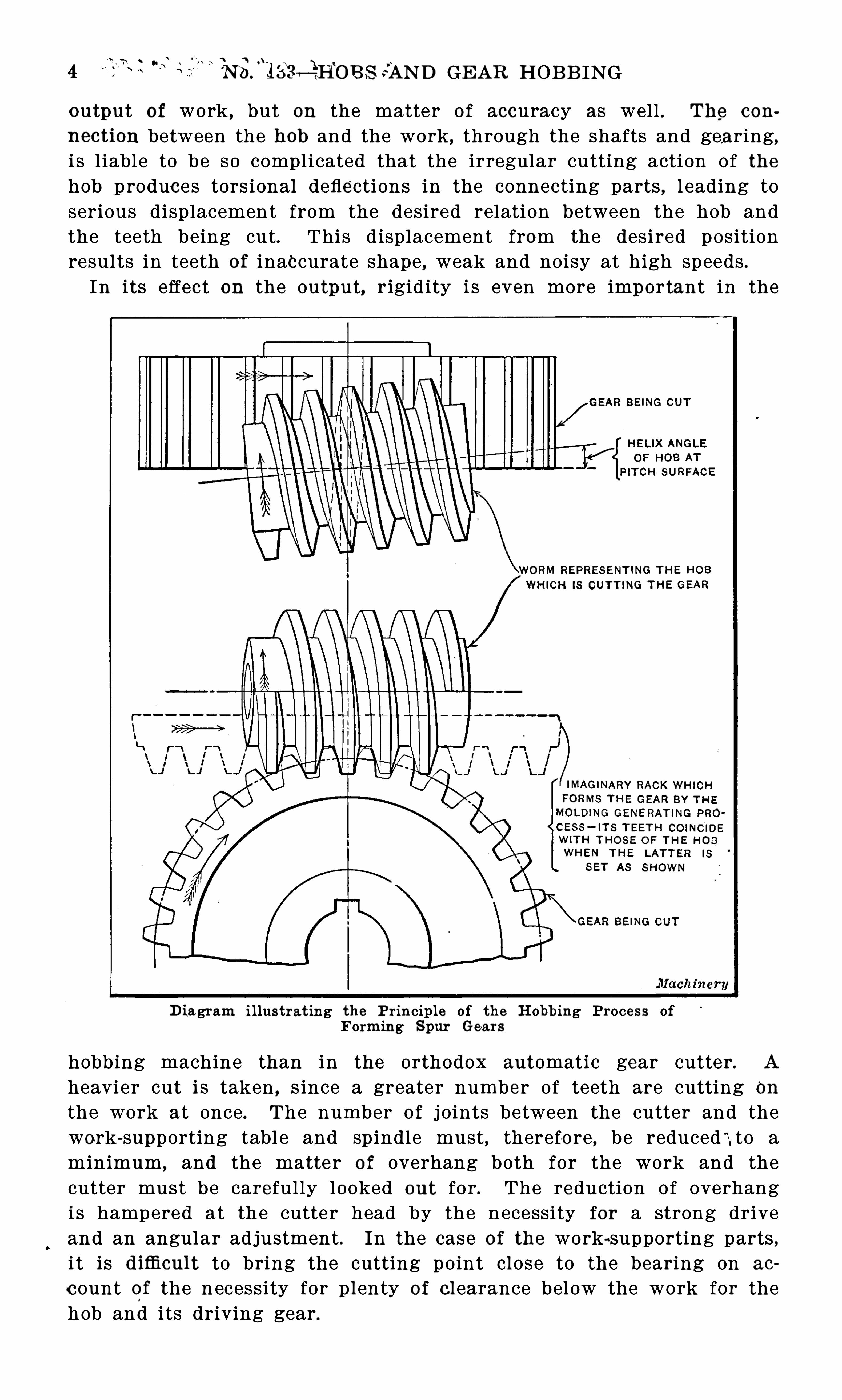
The hobbing process for cutting the teeth in spur and spiral gearsi s beginning to be very widely used . The principle of this method isshown diagrammatically in the accompanying illustration . In thelower part Of the il lustration is shown an imaginary rack ( in dottedl ines ) ; this rack is in mesh with the gear, the teeth o f which are
to be formed , and if the blank could be imagined asmade Of aplasticmaterial , the rack, i f moved along as indicated by the arrow, whilethe gear rotated to correspond , would form theoretical ly correct teethin the gear blank . The teeth of this rack coincide with the outl ineso f the worm shown in full l ines , thi s latter having been set at such anangle as to make the teeth on its front s ide parallel with the axis Of
the gear . In other words , i t has been set at the angle of its helix ,measured at the p itch l ine . This worm, when properly fluted , formsthe hob for cutting the gear teeth . I t wil l be seen that the teeth o f the
hob ,when set in thi s position , correspond with the teeth of the rack .
I f,now, the hob and blank be rotated at the ratio required by the
number o f threads in the hob and the number of teeth in the gear ,this movement wil l cause the teeth of the hob to travel l engthwise inexactly the same way as the teeth of the imaginary rack would travel ,i f in mesh with the gear, th e teeth of which are to be cut. I t will thusbe seen that the h ob fulfi l l s the requirements necessary for moldingthe teeth o f the gear to the proper form. In practice the hob isrotated in the required ratio with the work , and fed gradually throughit from one side Of the
-
face to the other. When i t has passed throughonce,
‘the work i s completed .
O f the great number of machines buil t during the past few yearsinvolving this principl e , many are arranged for cutting Spiral gearsas well as spur gears . Of course , all of the machines capable Of
cutting sp iral gears are capable of cutting spur gears al so . The
sp iral gear-hobbing machine bears about th e same relat i on to the plainspur gear-hobbing machine that the universal does to the plain milling machine . The added adjustments and mechanism required ineach case tend to somewhat limit the capacity of th e machine in taking heavy cuts although they add to its usefulness by extending therange of work I t is capable o f performing.
R equirements o f G ear H o b b ing Mach in e s
The requirements o f the successful gear hobbing machine are
First. A frame and mechanism of great rigidity .
S econd . Durable and powerful driving mechanism.
Third . Accurate indexing mechanism .
The first requirement is one of great importance , not only in itsinfluence on the heaviness of the cut to be taken and the consequent
3 4 75 97
NSJEM OB S SAN D GE AR HOB B ING
output of work , but on the matter O f accuracy as well . The con
nection between the hob and the work, through the shafts and gearing,i s l iable to be so complicated that the irregular cutting acti on Of thehob produces tors ional deflections in the connecting parts , l eading toserious displacement from the desired relati on between the hob andthe teeth being cut. This displacement from the desi red positionresul ts in teeth of inaccurate shape , weak and noisy at high speeds .I n i ts effect on the output, r igidity i s even more important in the
D iagram i llustrat ing the P rin ciple of the H obb ing Process ofForming Spur Gears
hobbing machine than in the orthodox automati c gear cutter. A
heavier cut i s taken , s ince a greater number of teeth are cutting On
the work at once. The number o f j oints between the cutter and thework-supporting tabl e and spindle must, therefo re, be reduced
“-, to a
minimum , and the matter o f overhang both for the work and thecutter must be carefully l ooked out for . The reduction O f overhangi s hampered at the cutter head by the necessity for a strong driveand an angular adjustment . In the case o f the work-supporting parts ,i t is difli cult to bring the cutting point close to the bearing on ao
count o f the necessity for plenty o f cl earance below the work for thehob and its driving gear .
SPUR AN D S PIRAL GE AR HOB S 5
The matter of design Of the driving mechanism for the hob and thework is a difficul t one . N ot o nly must i t be rigid for the sake of ac
curacy, as previously ex-plained , but careful attention must be givento durabil i ty as well . I t requires great skil l to design a durablemechanism for the purpose within the l imitations imposed— in thecutter head by the necessity for reducing the overhang, and in thework table by the high speed required for cutting smal l gears .S ince the indexing wheel works constantly and under considerable
load , both the wheel and worm must be built of such materials aswil l preserve the i r accuracy after l ong continued use . Particularattention should be given to the homogene i ty of the mate rial o f theindex worm-wheel , to make sure that it does no t wear faster on one
side than on the other.The fie ld of the hobbing process for cutting spur gears has
,perhaps
,
not yet been definite ly determined . In some work it appears to havegreat advantages over the usual type Of automatic gear—cuttingmachine , while in other cases i t seems to fal l behind . I t wil l doubtl ess require continued use , with a variety of work , and for a con
siderable l ength of time , to determine just what cases are best suitedfor the hobbing machine , and for the machine with the rotating diskcutter. I t is quite probable that in the future neither o f them wil lo ccupy the field to the exclusion of the other.
CHAPTER I
H OB S F OR S PUR A N D S PIRA L GEAR S
In exp laining the methods used in the design Of hobs for spurgears , i t is bes t to assume a practical example . S uppose that thegears are to be cast iron , with 1 20 t eeth , 1 6 diametral p it ch andinch width of face . The pitch diameter, hence , i s inches . Thehole
'
in the hob for the spindle i s to be 1 14 inch in diameter with a1A-square inch keyway , the hob to be run at high speed .
F o rm and D imens ions o f Too th
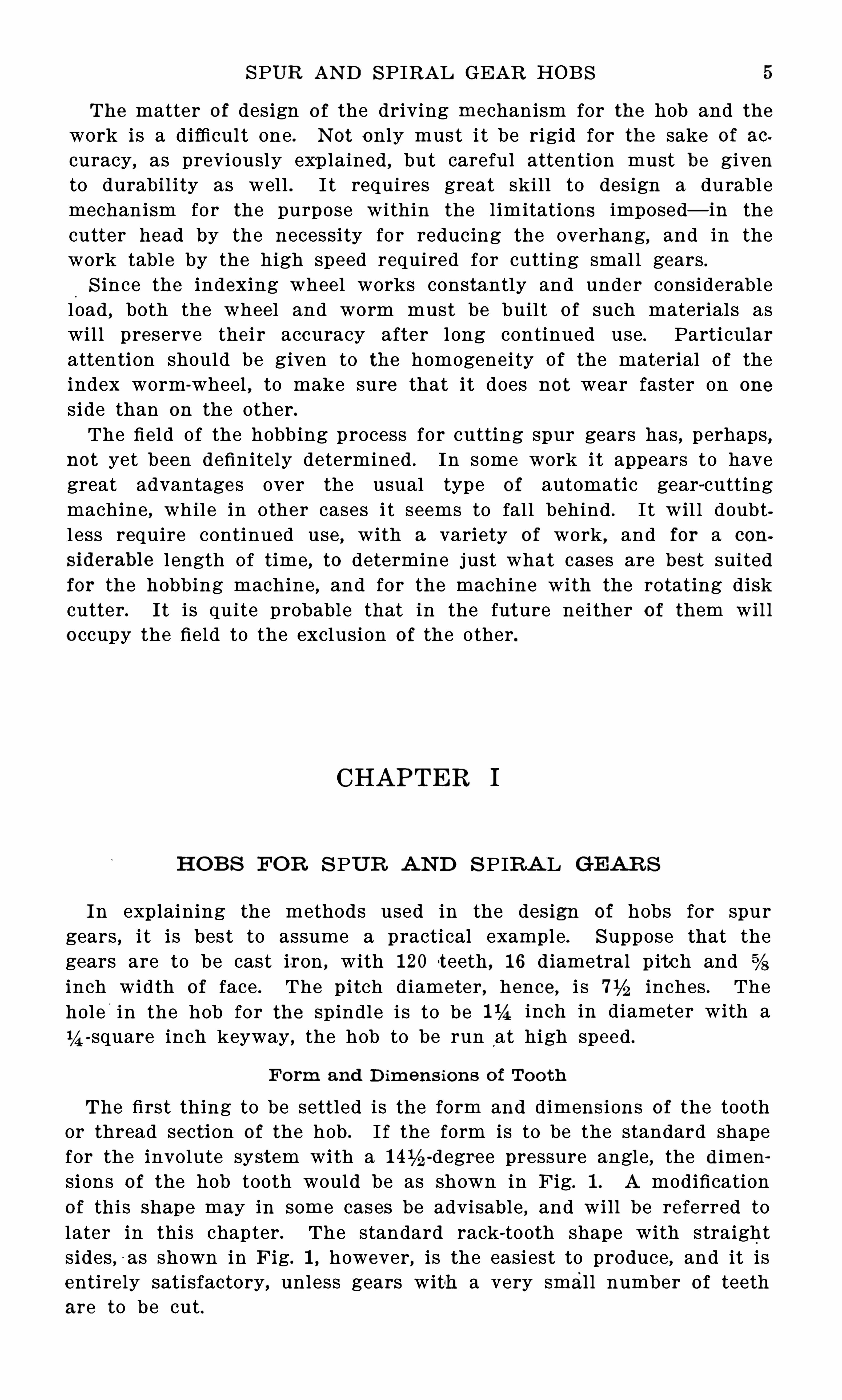
The first thing to be settled is the form and dimensions of the toothor thread secti on of the hob . I f the form is to be the standard shapefor the involute syst em with a -degre e pressure angle , the dimen
si ons o f the hob tooth would be as shown in Fig. 1 . A modificationo f this shape may in some cases be advisable , and will be re ferred tolater in this chapter . The standard rack-tooth shape with straightsides , - as shown in Fig. 1 , however, is the easiest to produce , and it isentire ly sati sfactory, unless gears with a very smal l number of teethare to be cut.
6 N o . 1 33— HOB S AN D GEAR HOB B ING
The circular p i tch corresponding to 1 6 diametral p i tch isinch , which is obtained by dividing by 1 6 . The thicknes s of
the tooth on the p itch l ine is one-hal f o f the circular pitch , or
The height o f the tooth above the p i tch l ine is equal to the reciprocalof the diametral p i tch
“
p lus the clearance , which latter i s equal toOf the thickness at the pitch l ine . Hence, the height of the toothabove the p itch l ine equals inch . This distance equal s the space in the gear below the p itch l ine .
The depth Of the too th Of the hob bel ow the p itch l in e is usuallymade greater than the distance from the p itch l ine to the top Of thetooth . The extra depth should be equal to from one-hal f to one timesthe cl earance . On small p i tches , one times the cl earance is not too
great an allowance , and , therefore, the depth below the p itch l ine ismade equal to making the whole depth of
F ig. 1 . S tandard H ob Too th D imensions
tooth equal to The extra d epth at the root Of the thread i s toall ow for a larger radius at the root , so as to prevent cracking inhardening. The radius may then be made equal to two t imes thecl earance, i f desired . In the
O
illustration, however, the radius is madeequal to o f the whol e dep th of the tooth . The top corner of thetooth is rounded off with a corner tool to a radius about equal to theclearance , or say inch . This corner is round ed to avoid unsightlystep s in the gear tooth flank near the root. Having Obtained the hobtooth dimensions , the principal dimensions of the hob may be workedout with relation to the rel ief, the diameter of the hole and the s izeo f the keyway.
R e lief o f H ob To oth
The proper rel ief for the too th is a matter generally decided byexp erience . We may say that, in general , i t should be great enoughto give plenty Of clearance on the side of the too th , and on hobs o f
-degree pressure angle the peripheral rel i ef is , roughly speaking,about four times that on the side . F or cutting cast iron with a hob
of the p itch in question , a peripheral rel ief O f inch wil l givesatisfacto ry results ; for steel , this cl earance should be somewhat in
SPUR AN D S PIRAL GE AR HOB S 7
creased. The amount of rel ief depends , necessarily , also upon thediameter o f the hob .
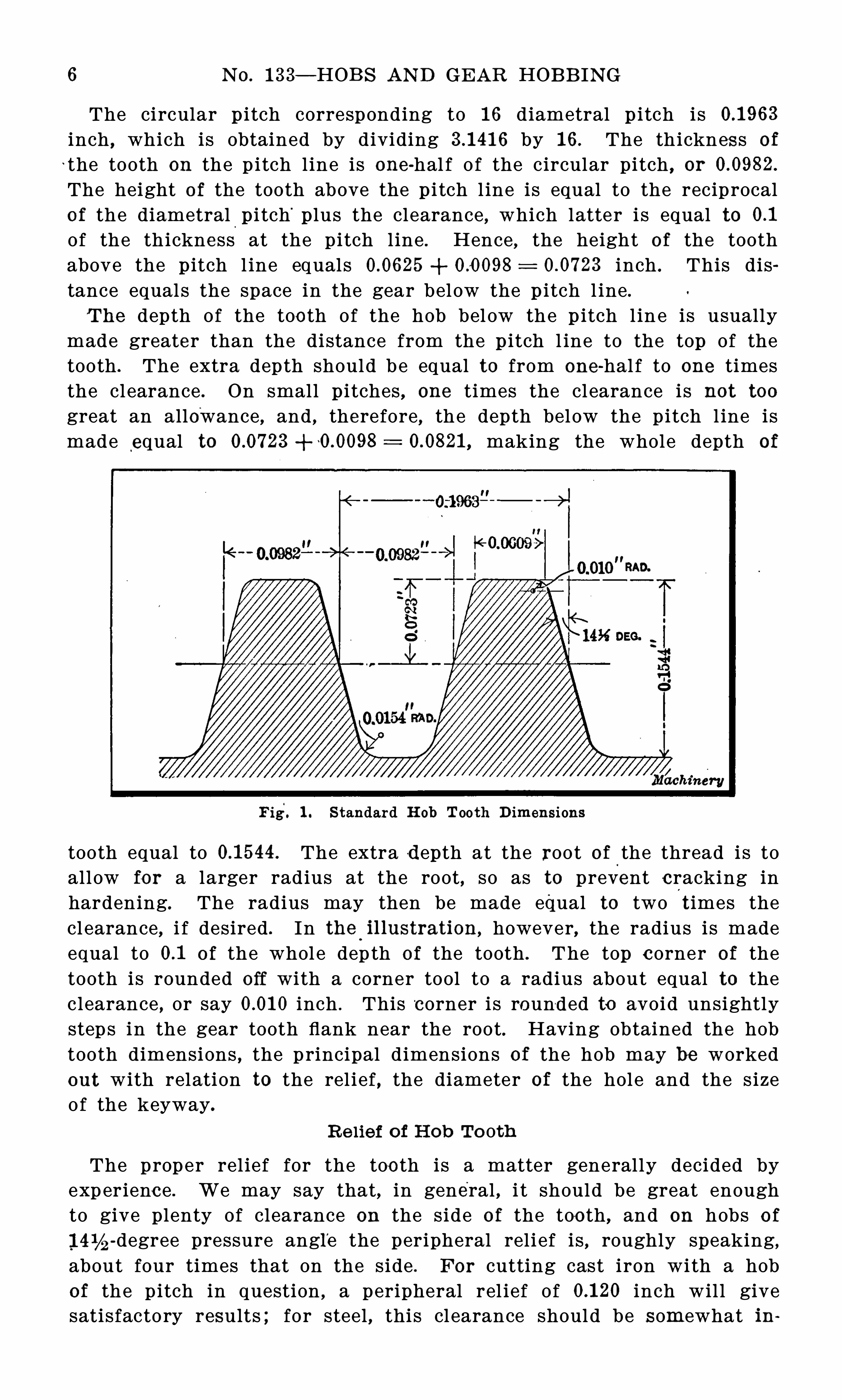
With a peripheral rel ief o f inch , the greatest depth of thetooth space in the hob must be The gashwill be made with a cutte r or tool with a 20-degree included angle
,
inch thick at the point, and so formed as to produce a gash witha half-circular section at the bottom . The depth of the gash should
be inch deeper than the greatest depth of the tooth space , or aboutinch .
Fig. 2 . H ob wi th Twelve Gashes or Flutes
Thic%n ess o f Met a l at % e yway
The radius Of the hob blank should be equal tothe thickness of the stock between the keyway and the bottom Of theflute . I f we use a 3-inch bar, we can turn a hob blank 294 inches indiameter from this, which would allow sufii cient stock to be turnedfrom the outer portion o f the bar to remove the decarbonized surface .
I f we make the blank inches in diameter we have inch ofstock over the keyway , which is sufficient .
N umb e r o f F lut esThe number o f gashes or flutes depends on many factors . In Fig.
2 i s shown an end view of a hob with twelve gashes . This numbergives plenty of cutting teeth to form a smooth tooth surface on the
gear without showing prominent t ooth marks . A larger number Of
8 N O. 1 33—HOB S AND GEAR HOB B ING
gashes wil l not, in practice , give a better tooth form , but simply in
creases the l iabil ity to inaccuracies due to the forming p rocess andto distortion in hardening. This number o f gashes also l eaves p l entyo f stock in the teeth, thus insuring a l ong l ife to the hob .
S t ra igh t or S p ira l F lut es
The questi on whether the gashes should be parallel with the axisor normal to the thread hel ix is one that is not
'
easily answered . I tmust be admitted that when the angle of the thread is great
,the
cutting action at both sides O f the tooth is not equal in a hob with astraight gash ; but in cases of hobs fo r fine p i tch gears, where the hobsare o f comparatively large diameter, thus producing a small threadangle, the parallel gash is more practical because i t i s much easier to
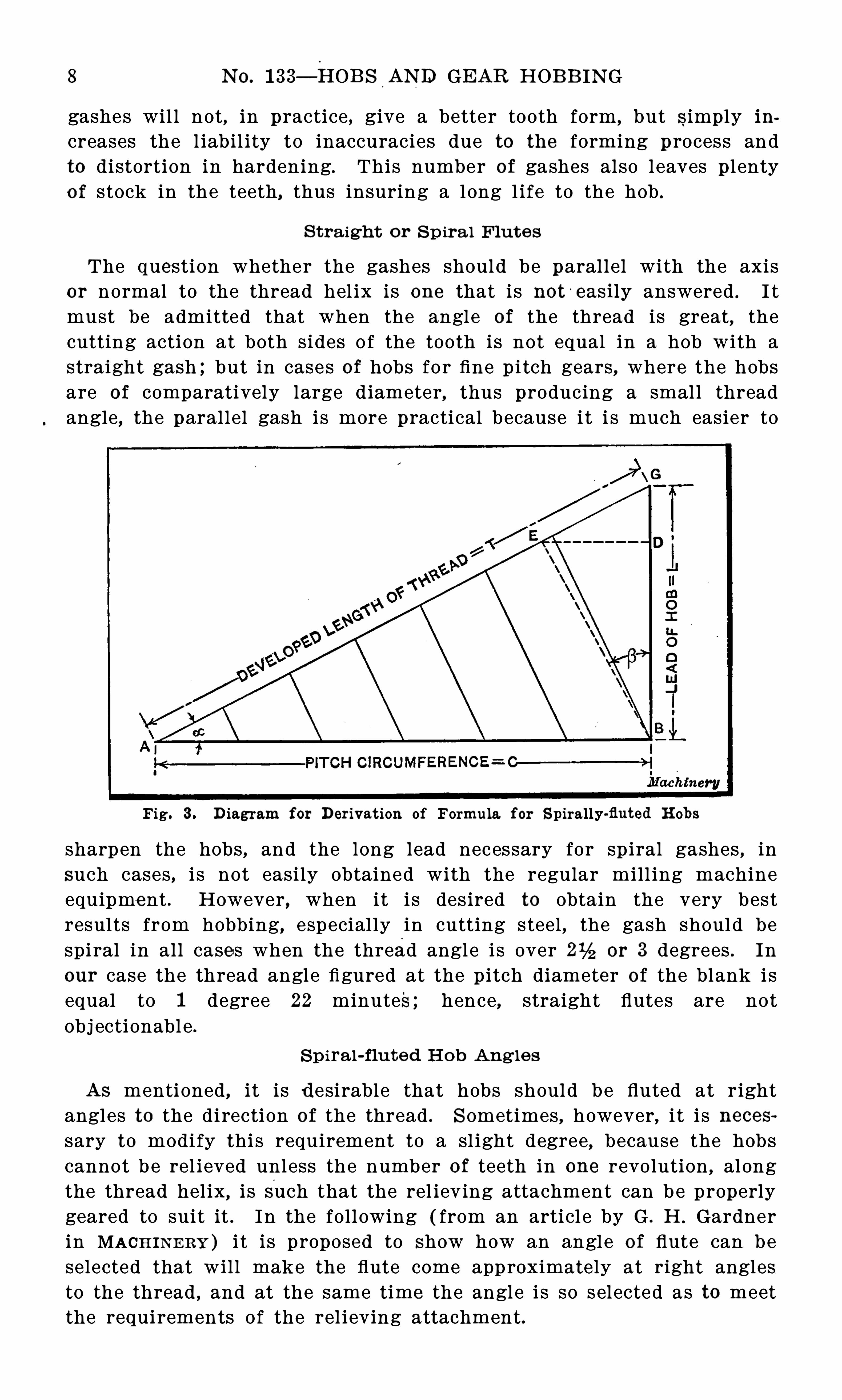
Fig. 3 . D iagram for Derivat ion of Formula for S pirally-fluted H obs
sharpen the hobs , and the long lead necessary for spiral gashes , in
such cases , i s not easily obtained with the regular mill ing machineequipment . However , when it i s des ired to Obtain the very bestresults from hobbing, especial ly in cutting steel , the gash should bespi ral in all cases when the thread angle is over or 3 degrees . In
our case the thread angle figured at the pitch diameter of the blank isequal to 1 degree 22 minutes; hence, straight flutes are notObj ectionabl e .
S p ira l-flut ed H ob Ang les
As mentioned, i t is desirable that hobs should be fluted at r ightangles to the di rection of the thread . S ometimes , however, i t i s necessary to modi fy thi s requirement to a sl ight degree, because the hobscannot b e rel ieved unless the number of teeth in one revolution , alongthe thread hel ix, i s Such that the rel ieving attachment can b e properlygeared to suit it . In the foll owing ( from an articl e by G . H . Gardnerin MACH IN E RY ) i t i s proposed to Show how an angle o f flute can beselected that will make the flute come approximately at right anglesto the thread , and at the same time the angle i s so selected as to meetthe requirements of the rel ieving attachment.
SPUR AN D SPIRAL GE AR HOB S 9
L et C’ pitch circumference ;T: devel oped length Of thread in one turn ;N number of teeth in one turn along thread hel ix ;F number of flutes ;a 2 angle Of thread hel ix .
Then ( see Fig. 3 )
0 + l ength of each small division on pitch circumference .
(C —'
F ) X cos a length of division on developed thread .
0 cos a T.
Hence( C —z - F ) Cos a cos
za
N ow, i f a. 30 degrees , N 1 F
a 4 5 degrees , N 2 F ;
a 60 degrees , N 4 F .
In most cas es , however, such simple relations are not obtained .
S uppose for example that F i— 7, and a = 35 degrees . Then N =
and no gears could be selected that would rel ieve this hob .
B y a very sl ight change in the sp iral angl e of the flute , however, wecan change N to 1 0 or in either case we can find suitable gearsfor the re l ieving attachment.
The rule for finding the modified spiral lead of the flute is
Multiply the lead of the hob by F, and divide the product by the
d ifference between the desired value of N and F .
Hence , the lead of flute required to make N 1 0 is
Lead Of hob ( 7 +
TO make N = 1 01 A) , we haveL ead of flute = lead Of hob X ( 7 —2
Fro‘
m this the angle o f the flute can easily be found .
That the rule given is correct wil l be understood from the foll owing consideration . Change the angle o f the flute hel ix 6 so that AGcontains the required number of parts N desired . Then E G contains
N — F parts ; but cot ,B= B D — E D ,
'
and by the law of s imi lartriangles:
F
B D and E D
N
The lead Of the spiral of th e flute, however, i s C' X cot fi.
Hence , the required lead of Spiral of the fluteF
C X cot fi L
N — F
This simple formula makes it possible always to flute hobs so thatthey can be conveniently re l ieved , and at the same time have the flutesat approximately right angles to the thread .
1 0 N O. 1 33— HOB S AN D GEAR HOB B IN G
Graph ica l Me th od
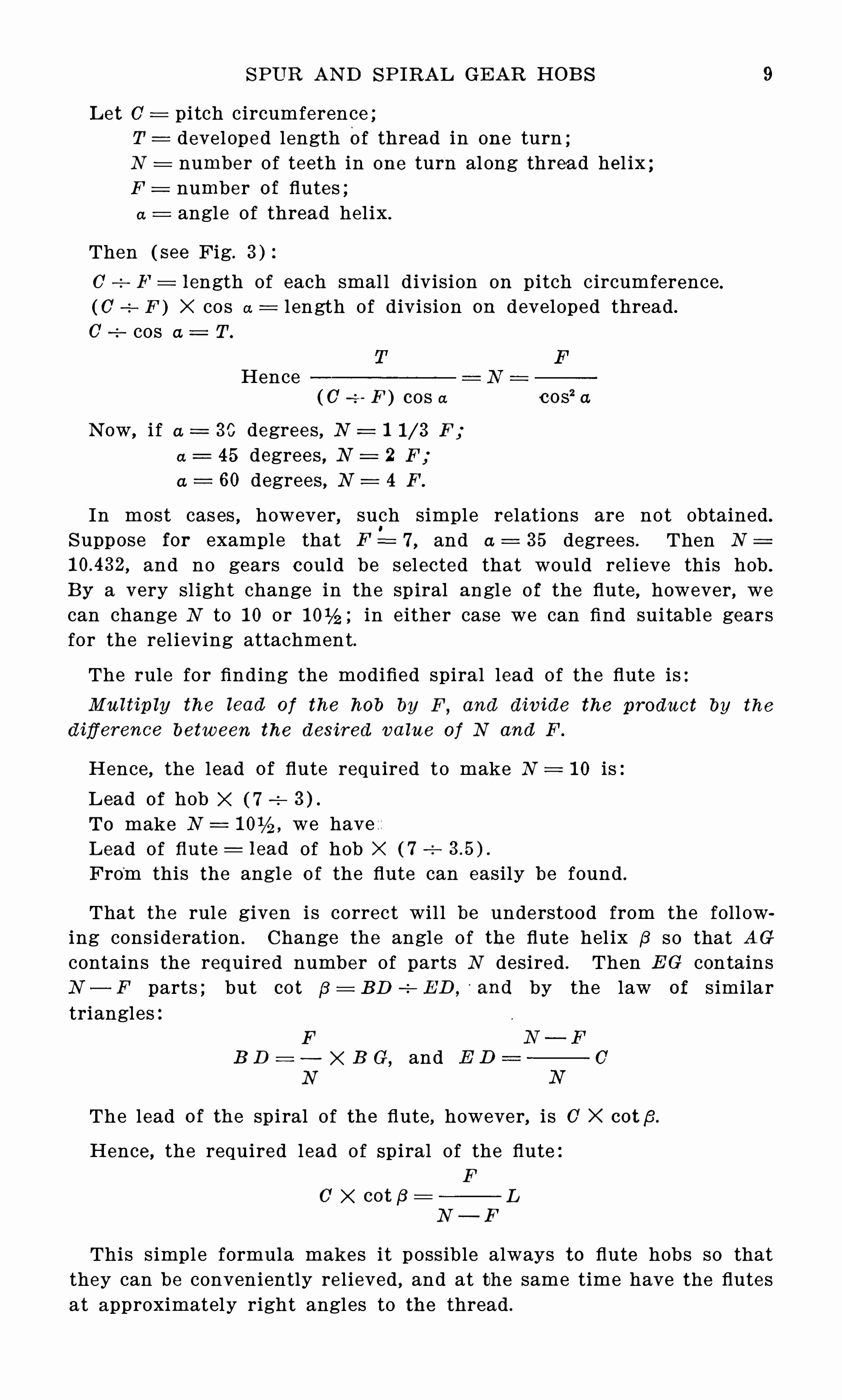
The angl e of the flutes, determined so as to avoid difii culties inrel ieving, may be found graphical ly as foll ows:First, lay Off a basel ine AA , Fig. 4 , o f any convenient length . Then erect the
'
perpen
dicular AO making it equal to the developed length O f the p i tch cir
cumference of the hob . From 0 draw l ine CD parallel to the base l ineAA and o f a length equal to the l ead of the hob . N ow drawn diagonalAD which represents the thread . D ivide AO into as many equal partsas there are flutes in the hob , as a, b and c. From 0 and a draw linesthrough and at right angles to the diagonal AD , as CE and OF . Thenl ength E F equal s the p itch Of the flutes on the thread when the gash
Fig. 4 . Graphical M ethod of Finding Gash ing Angle and N umber of Flutesfor which B ac%ing-off Attachment should be set for Spiral-fluted H obs
ing i s at right angles to the thread . To proceed , divide AD into acertain number o f equal parts , the length o f these parts to be as nearto the length E F as possible . S tep Off these d ivisions on AD , andthrough the division nearest to E , as at G, draw a l ine from C’ to thebase l ine intersecting the base l ine at B . This l ine C'B represents thegash
,l ine AB the l ead o f the gash , and the number O f divis ions in the
l ine AD equal s the number of flutes to one revolution of the hob , forwhich we must gear the machine .
To get the exact length Of AB , d ivide the number O f divisions inAG by the number of d ivisions in GD and multiply the resul t by thel ength of the l ine CD or the l ead o f the hob . The angle a which isthe angle for gashing can be found by scal ing the d iagram . F or
example , l e t the hob be 2 inches pitch diameter, l ead 5 inches, andnumber Of flutes 8.
We first drawn base l ine AA , and the l ine AO inches long whichi s the p itch circumference . N ow draw CD 5 inches l ong, and then
S PUR AN D SPIRAL GEAR HOB S 1 1
draw line AD . We now divide AC into eight equal parts and drawl ines from G and a through and at right angles to AD ,
intersecting AD,
at E and F . S etting the dividers,to length E F we step off l ine AD
and find that thi s length E F will go into AD a l ittle over thirteentimes ; so we divide this l ine AD into thirteen equal parts . I t is nownecessary to gear the mach ine for thirteen flutes to one revolution of
the hob .
The d ivision neares t to E i s G, so by drawing a l ine from 0 throughG we intersect the base l ine at B . In the line GD there are five
divisions , and in the l ine AG
there are eight divisions . Thelead of the hob is five inches , sothat the l ength of the lead for
8
the gash o r AB i s— X 5 : 8
Thread in g th e H ob
The linear p it ch of the hoband the circular pitch of thegear, when considered in action,
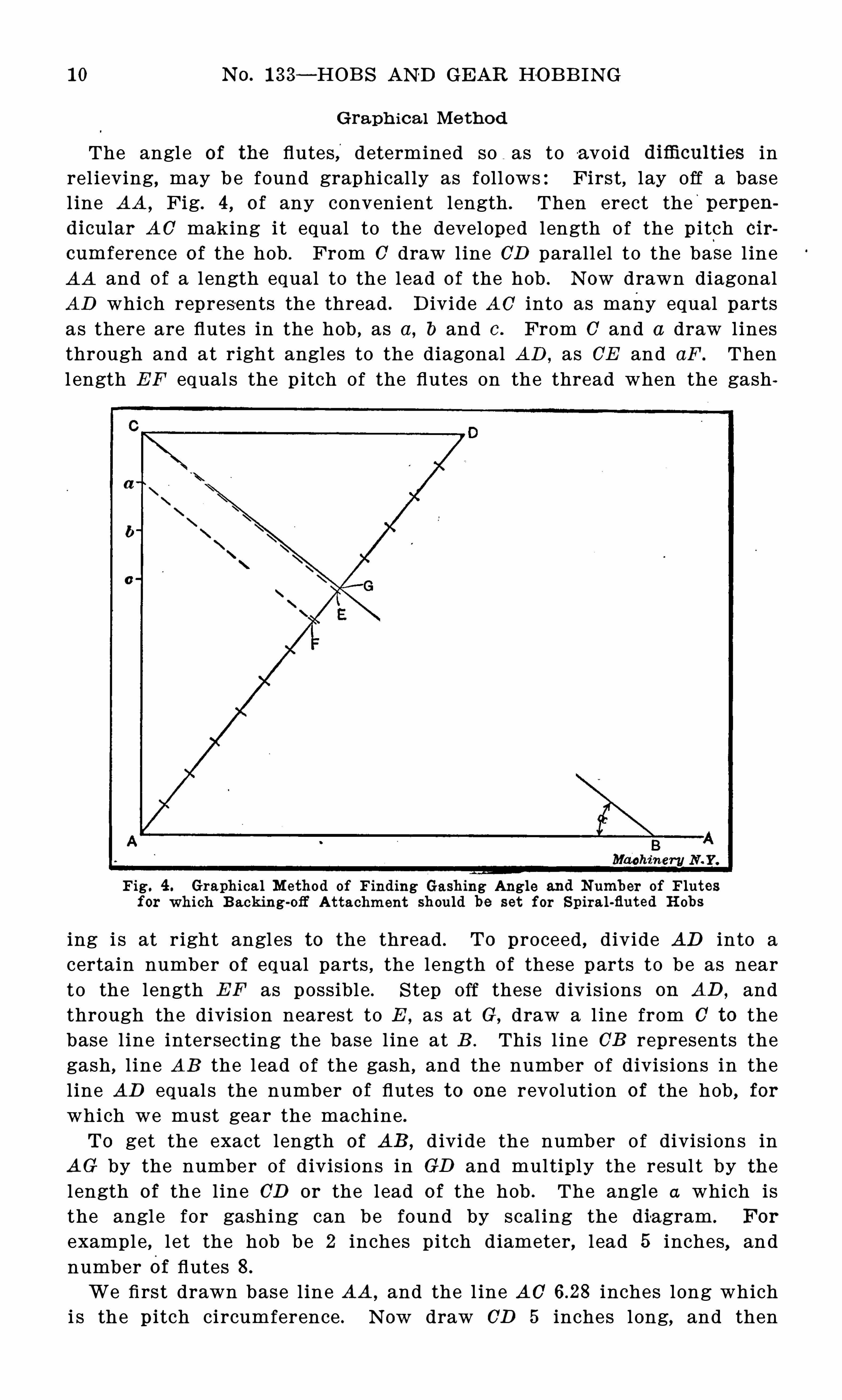
Fig. 5 . Threading Tool for H obare to each other as 1 i s to thecosine o f the thread angle . In
the present case they do not differ apprec iably and may be consideredas equal . In cases where the differenc e is over the true l inearpitch should be used.
The change-gears for the lathe may be figured by the formula
Gear on lead-s crew lead o f lead-screw
Gear on stud l inear pitch o f hob
On a lathe with a lead-screw of six threads per inch , or a lead of
or inch , the gears that would give accurate enough resultsfor the present hob would be 28 teeth on the l ead-screw, and 33 teethon the stud .
Th read R e l iev ing To o l
In Fig. 5 i s shown the hob thread rel ieving tool . The front O f thetool is rel ieved with a 20-degree rake for clearance . The sides are
ground straight at a -degree angle to form the sides Of the thread ,
5
inches . B y measuring on thediagram with a scale we findthe gashing angle is 38 14 de
grees . Therefore, we will gearthe machine used in backing off
the hob for 1 3 flut es to one
revolution, and we will gear themill ing machine to cut a lead of8 inches , and at a gashing angleof 38 14 degrees .
1 2 N O. 1 33— HOB S AND GEAR HOB B ING
and are at an angle of 1 degree 22 minutes with the vertical to cl earthe sides of the thread . A tool make l ike this can be sharpened bygrinding across the top without losing its size or form . I f the gasheswere made on the sp iral , the top of the tool should be ground to theangle o f the thread , as shown by the dotted l ine AB . In cases wherethe angle Of the thread is considerable , the angle o f the sides of thetool must be corrected to give the proper shape -to the hob tooth .
( S ee MACH IN ERY , May, 1 905, or MAOH I N ERY’
S R eference B ook N O. 32,
Formula for Planing Thread Tools %
) The point of the too% shouldbe stoned to give the proper radius to the fi l l et in the bottom Of the
hob tooth space .
H eat - t reatment o f H ob
The best practice in making the hob is to anneal it after i t has beenbored
,turned , gashed and threaded , the anneal ing taking place before
rel ieving the teeth . B efore hardening, the hob ought to be re-gashed
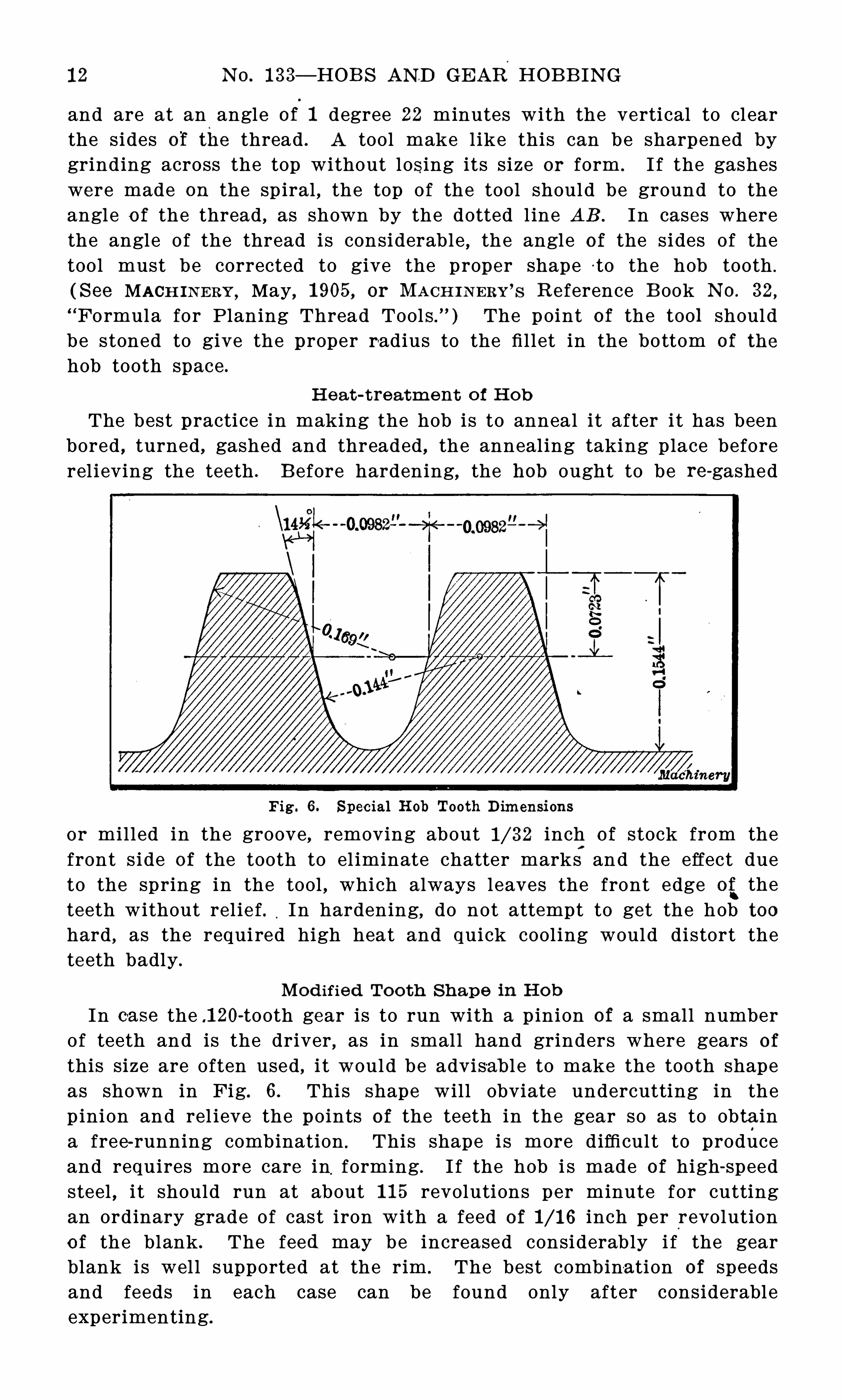
Fig . 6 . Spec ial H ob Tooth D imensi ons
or milled in the groove , removing about inch o f stock from thefront s ide o f the tooth to el iminate chatter marks
,
and the effect dueto the spring in the tool , which always leaves the front edge of theteeth without rel ie f. In hardening, do not attempt to get the hob toohard , as the requi red high heat and quick cool ing would distort theteeth badly .
Mod ified To o th S h ape in H o b
In case the .1 20-tooth gear is to run with a pinion of a small numberof teeth and is the driver , as in small hand grinders where gears of
this size are often used , i t would be advisab l e to make the tooth shapeas shown in Fig. 6 . This shape will obviate undercutting in thep inion and rel ieve the points o f the teeth in the gear so as to Obtaina free-running combination . This shape i s more difficul t to produceand requires more care in
,forming . I f the hob i s made of high-speed
steel , i t should run at about 1 1 5 revolutions per minute for cuttingan ordinary grade Of cast iron with a feed of inch per revolutionOf the blank . The feed may be increased considerably i f the gearblank is wel l supported at the rim . The best combina tion of speedsand feeds in each case can be found only after considerableexperimenting.
1 4 N o . l33— HOB S AN D GEAR HOB B IN G
spaced , or there may have been an error in the gears on the relievinglathe influencing the form ; the hob may also have been distorted inhardening ; i t may have been improperly handled in the fire or bath
,
or i t may have been so proportioned that i t could not heat or cooluni formly ; the grinding after hardening may be at faul t ; the holemay not have been ground concentric with the form ,
thus causing theteeth on one side of the hob to cut deeper than on the o ther. Any
one or a combination O f several O f these condition s may have thrownthe teeth out of the true hel ical path .
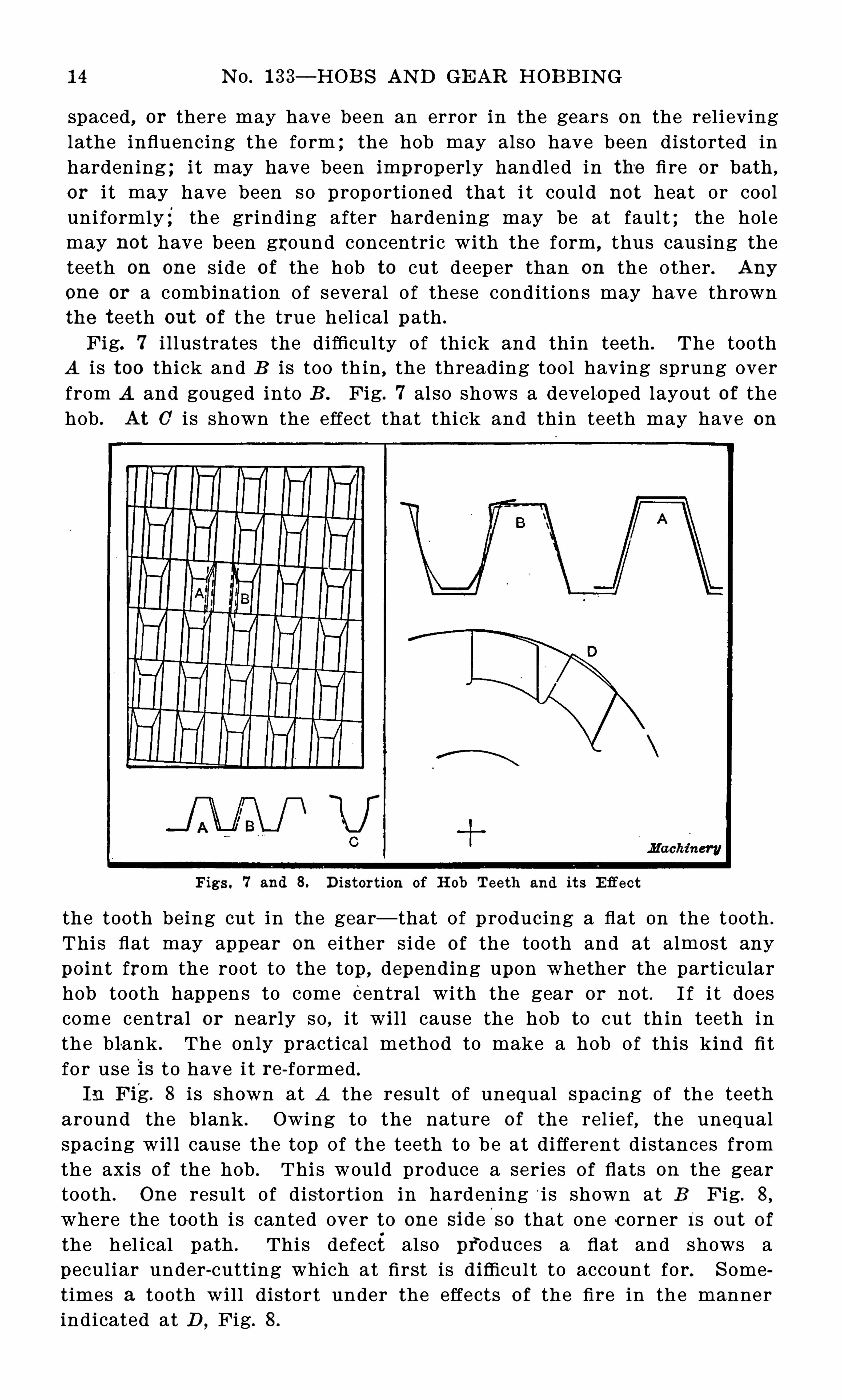
Fig. 7 i l lustrates the difficulty of thick and thin teeth . The toothA i s too thick and B i s too th in , the threading tool having sprung overfrom A and gouged into B . Fig. 7 al so shows a develo ped layout of thehob . At 0 i s shown the effect that thick and thin teeth may have on
Figs. 7 and 8. D istort ion of H ob Teeth and its E ffect
the tooth being cut in the gear— that of p roducing a flat on the tooth .
This flat may appear on either s ide o f the tooth and at almost anypoint from the root to the top , depending upon whether the particularhob tooth happen s to come Central with the gear or not . I f i t doescome central or nearly so , it wil l cause the hob to cut th in teeth inthe blank . The only practical method to make a hob of this kind fi tfo r use is to have i t re-formed .
I n F ig. 8 i s shown at A the resul t of unequal spacing of the teetharound the blank . Owing to the nature o f the rel ie f, the unequalspacing wil l cause the top of the teeth to b e at different d istances fromthe axis of the hob . This would produce a series of flats on the geartooth . One result O f distorti on in hardening ‘i s shown at B Fig. 8,
where the tooth i s canted over to one side'
so that one corner I S out o f
the hel ical path . This defect also pf oduces a flat and shows apeculiar under-cutting which at first is difficul t to account for. S ometimes a tooth will distort under the effects of the fire in the mannerindicated at D
,Fig. 8 .
S PUR AN D SPIRAL GEAR HOB S 1 5
These defects may be avoided by proper care and by having the
steel in good condition before forming. The blank should be roughedout, bored , threaded, gashed and then annealed before fin ish-formingand hardening. The anneal ing re l ieves the st resses in the steel due tothe roll ing process .
The proportions of the hob have a direct effect on distortion,in
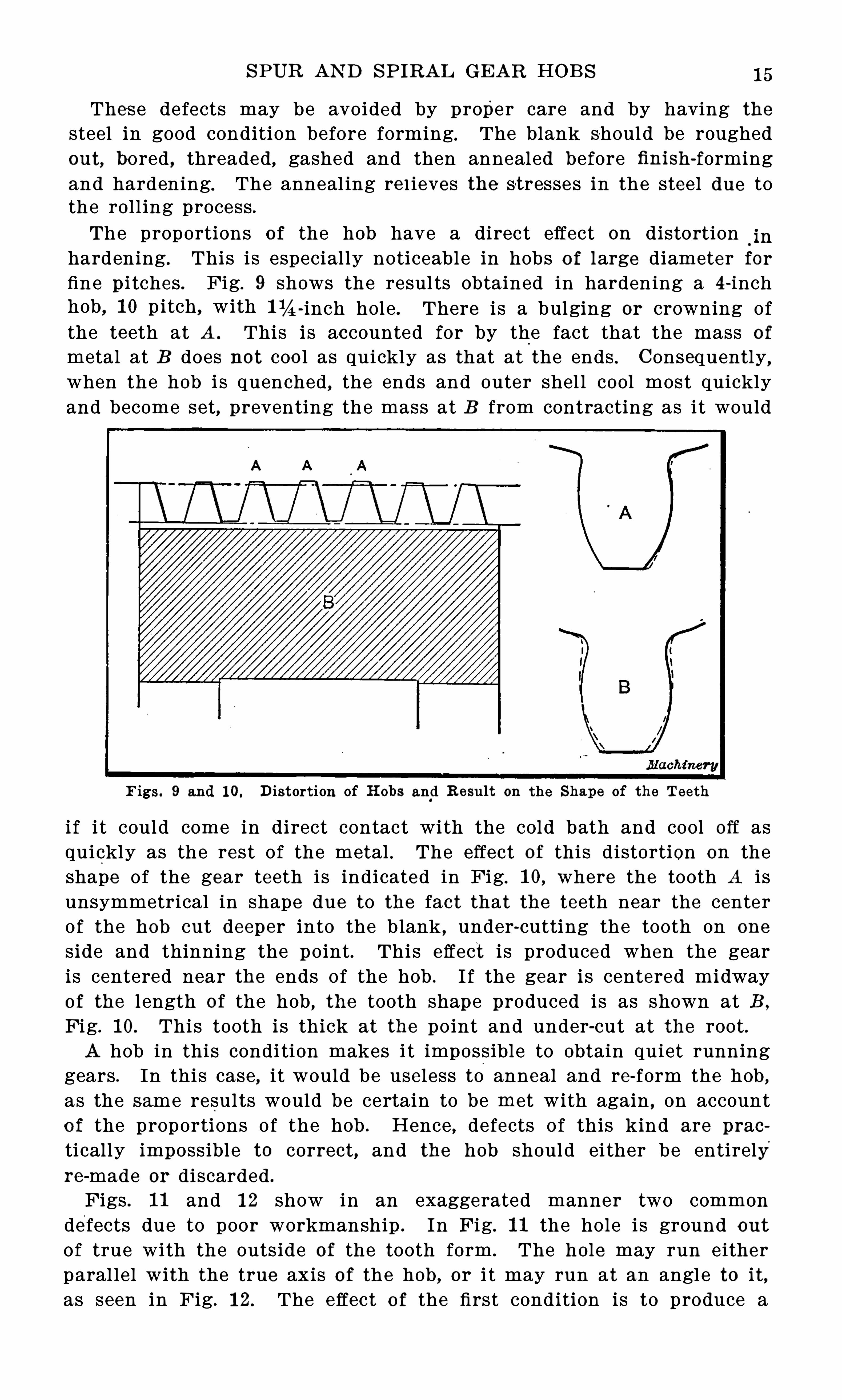
hardening. This is especial ly noticeable in hobs o f l arge diameter forfine p i tches . Fig. 9 shows the resul ts Obtained in hardening a 4 -inchhob , 1 0 pitch, with 1 14 -inch hole . There i s a bulging or crowning ofthe teeth at A . This is accounted for by the fact that the mass of
metal at B does not coo l as quickly as that at the ends. Consequently
,
when the hob i s quenched, the ends and outer shel l cool most quicklyand become set, preventing the mass at B from contracting as it would
Figs. 9 and 1 0. D istort ion of H obs and R esult on the Shape of the Teeth
i f i t could come in direct contact with the cold bath and cool Off asquickly as the rest of the metal . The effect of this distortion on theshape of the gear teeth is indicated in Fig. 1 0, where the tooth A isunsymmetrical in shape due to the fact that the teeth near the centerof the hob cut deeper into the blank , under-cutting the tooth on one
side and thinning the point . This effect i s produced when the gearis centered near the ends of the hob . I f the gear is centered midwayOf the l ength of the hob , the tooth shape produced is as shown at B ,
Fig. 1 0. This tooth is thick at the point and under-cut at the root .A hob in this condi tion makes i t impossible to obtain quiet running
gears . In this case, i t would be useless to anneal and re form the hob ,as the same resul ts would be certain to be met with again , on accounto f the proportions Of the hob . Hence , defects o f this kind are praotically impossible to correct, and the hob should ei ther be entirelyre-made or discarded .
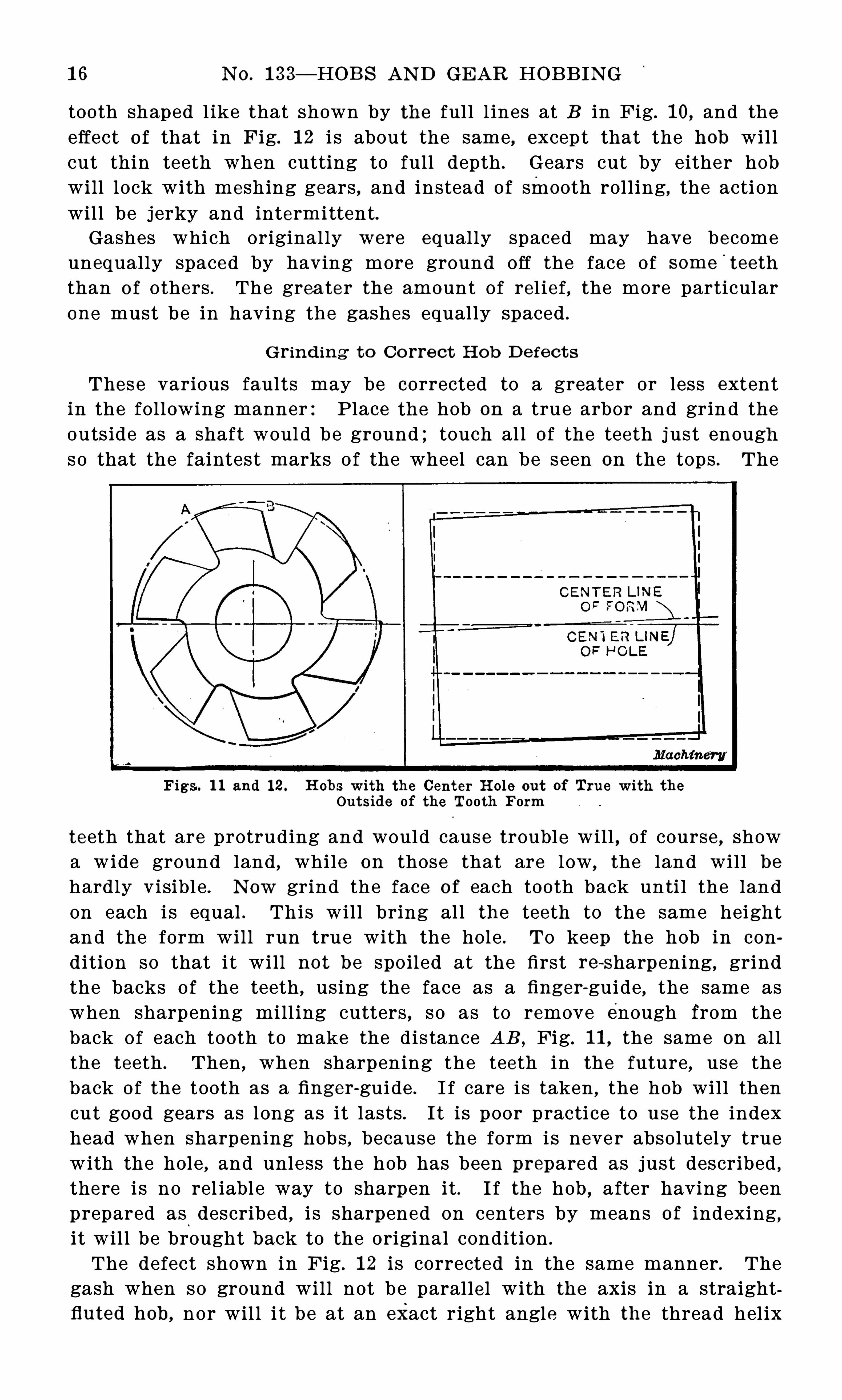
Figs . 1 1 and 1 2 show in an exaggerated manner two commondefects due to poor workmanship . In Fig. 1 1 the hole is ground out
Of true with the outside of the tooth form . The hole may run eitherparal lel with the true axis of the hob , or i t may run at an angle to i t,as seen in Fig. 1 2. The effect o f the first condition is to produce a
1 6 N O. 1 33— HOB S AN D GEAR HOB B IN G
tooth shaped l ike that shown by the ful l l ines at B in Fig. 1 0, and theeffect of that in Fig. 1 2 i s about the same, except that the hob wil lcut thin teeth when cutting to full depth . Gears cut by either hobwill lock with meshing gears , and instead Of smooth roll ing, the acti onwill be j erky and intermittent.Gashes which original ly were equally spaced may have become
unequally spaced by having more ground Off the face of some'
teeth
than o f others . The greater the amount of rel ief, the more particular
one must be in having the gashes equally spaced .
G r in d ing t o Co rre ct H ob D e fect s
Thes e various faults may be corrected to a greater or less extentin the fol lowing manner:Place the hob on a true arbor and grin d theouts ide as a shaft woul d be ground ; touch al l O f the teeth j ust enoughso that the faintest marks o f the wheel can be seen on the tops . The
Figs . 1 1 and 1 2 . H obs with the Cent er H ole out Of True with theOutside of the Tooth F orm
teeth that are protruding and would cause trouble will , of course , showa wide ground land , while on those that are low, the land will behardly visibl e . N ow grind the face o f each tooth back unti l the landon each i s equal . This will bring al l the teeth to the same heightand the form will run true with the hole . To keep the hob in condition so that i t will not be spoiled at the first re-Sharpening, grindthe backs o f the teeth , using the face as a finger-guide , the same aswhen sharpening mill ing cutters , so as to remove enough from theback of each tooth to make the dis tance AB , Fig. 1 1 , the same on allthe teeth . Then , when sharpening the teeth in the future, use theback of the tooth as a finger-guide . I f care is taken , the hob will thencut good gears as l ong as it lasts . I t i s poor practi ce to use the indexhead when sharpening hobs , because the form is never absolutely truewith the hole , and unless the hob has been prepared as just described ,there i s no rel iabl e way to sharpen it . I f the hob , after having beenprepared as described , i s sharpened on centers by means of indexing,i t wil l be brought back to the original condition .
The defect shown in Fig . 1 2 i s corrected in the same manner . Thegash when so ground will not be parallel with the axis in a straightfluted hob , nor wil l i t be at an exact right angle with the thread hel ix
SPUR AN D SPIRAL GE AR HOB S 1 7
in a spiral-fluted hob , because the teeth at the right-hand end are highwhile those at the left-hand end are low and the amount that must b eground off the faces o f the hob teeth W I I I be greater at one end thanat the other. The angle wil l be sl ight , however , and o f no consequence .
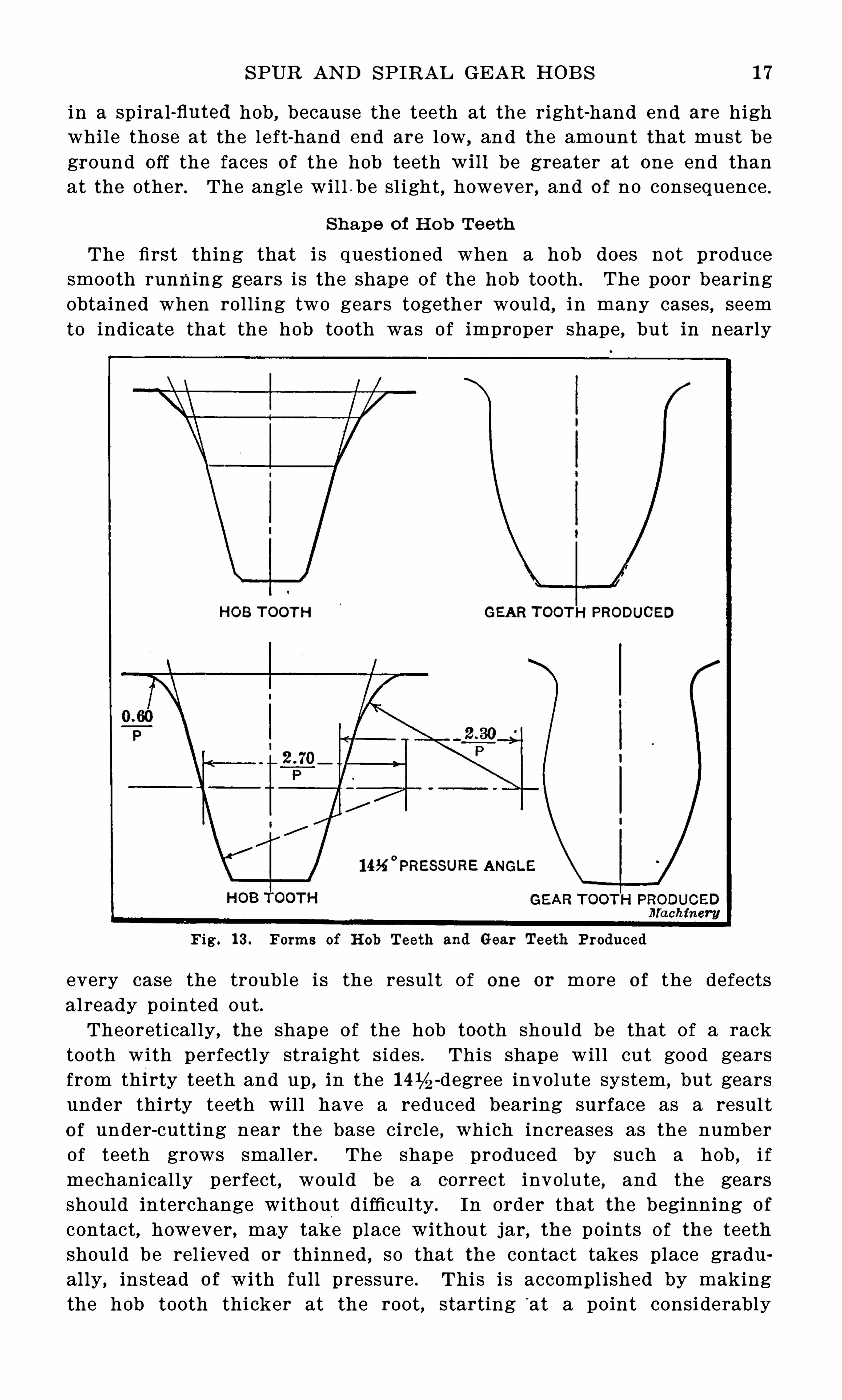
Sh ape o f H o b Te eth
The first thing that is questioned when a hob does not producesmooth running gears is the shape of the hob tooth . The poo r bearingobtained when roll ing two gears together would , in many cases , seemto indicate that the hob tooth was Of improper shape
,but in nearly
HOB TOOTH GEAR TOOTH PRODUCED
I 4 x°
PRESSURE ANGLE
Fig . 1 3 . Forms of H ob Teeth and Gear Teeth Produced
every case the trouble i s the resul t of one or more o f the defectsalready pointed out.Theoretical ly , the shape of the hob too th should be that of a rack
tooth with perfectly straight sides . This shape will cut good gearsfrom thirty teeth and up, in the -degree involute system , but gearsunder thirty teet h will have a reduced bearing surface as a resul to f under-cutting near the base circle , which increases as the numberof teeth grows smal ler . The shape produced by such a hob , i fmechanically perfect , would be a correct involute , and the gearsshould interchange without difficulty. In order that the beginning o f
contact,however , may take place without jar, the points of the teeth
should be rel ieved or thinned , so that the contact takes place gradually, instead Of with full pressure . This is accompl ished by makingthe hob tooth thicker at the root, starting
‘
at a point considerably
1 8 N O. 1 33— HOB S AN D GEAR HOB B IN G
below the p i tch l ine . This is i l lust rated in the upper portion of Fig.
1 3, which shows the standard Shape adopted by the B arber-Colman Co .
The Shape o f the tooth produced is also Shown . The full l ines showthe shape generated , and the dotted , the lines O f the true involute.
The amount removed from the points is greater on large gears andless on small p ini ons, where the l ength of contact is
'
none too greateven with a ful l shaped tooth , and where any great reduction mustb e avo ided . This Shape of hob tooth does not , however , reduce undercutting on small p inions . The fact that hobbed gears have under-cutteeth in small p inions , while those out with rotary cutters have radialflanks with the curve above the p itch l ine corrected to mesh with
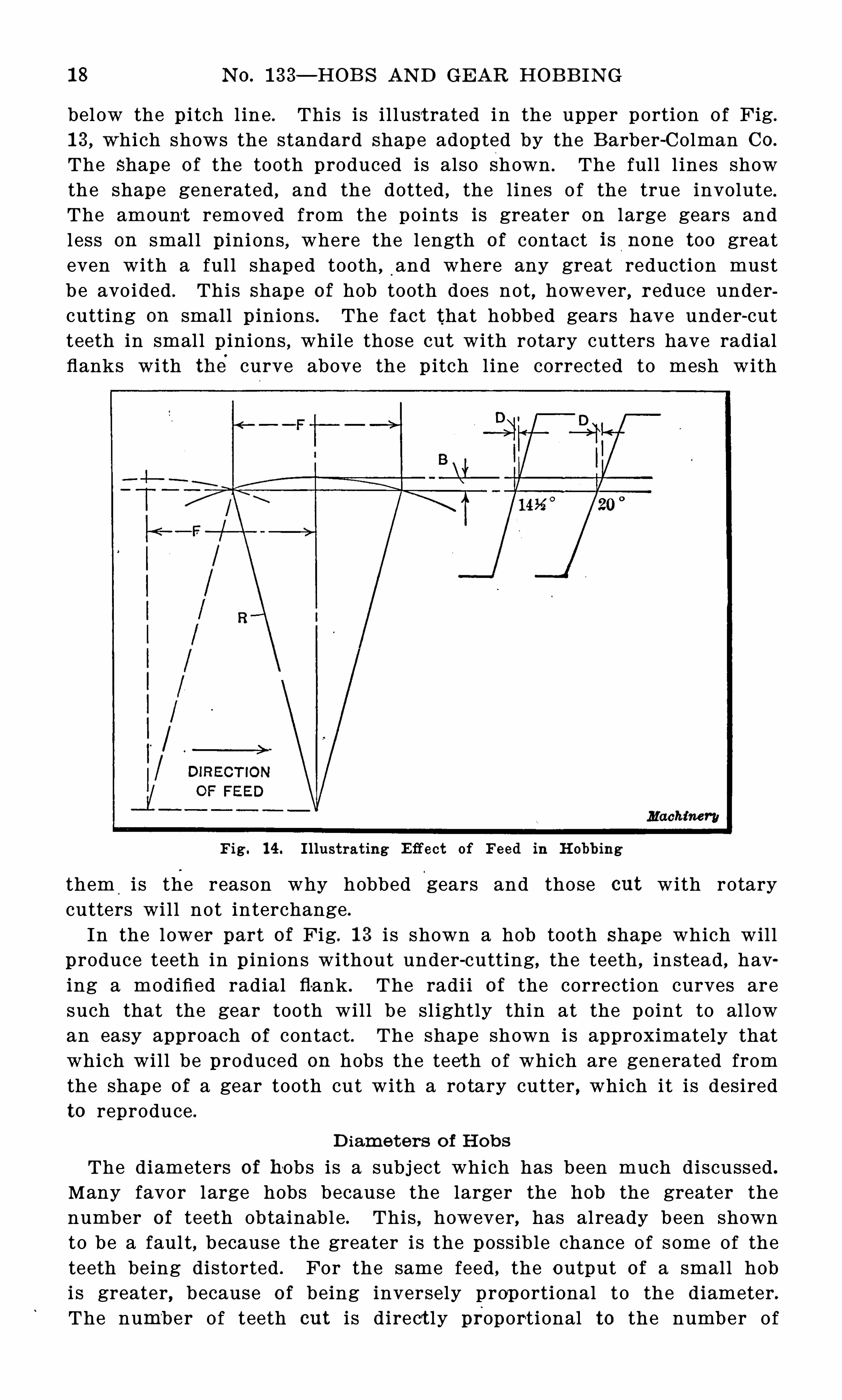
Fig. 1 4 . Illustrat ing E ffect of Feed in H obbing
them,
i s the reason why hobbed gears and those out with rotarycutters wil l not interchange .
In the lower part of Fig. 1 3 i s shown a hob tooth Shape which willproduce teeth in p inions without under-cutting, the teeth , instead , having a modified radial fl-ank . The radi i o f the correction curves aresuch that the gear tooth will b e sl ightly thin at the point to al lowan easy approach o f contact. The shape shown is approximately thatwhich will be produced on hobs the teeth Of which are generated fromthe shape of a gear tooth cut with a ro tary cutter , which it is desiredto reproduce .
D iamet ers o f H ob s
The diameters of hobs is a subj ect which has been much discussed .
Many favor large hobs because the larger the hob the greater thenumber of teeth obtainable . This , however, has already been shownto be a faul t , because the greater is the possible chance Of some Of theteeth being distorted . For the same feed , the output of a small hobi s greater, because o f being inversely prop ortional to the diameter.The number Of teeth out i s d irect ly proportional to the number Of
S PUR AN D SPIRAL GEAR HOB S 1 9
revolutions per minute o f the hob . The number of revolutions depends on the surface speed
’
Of the hob ; therefore , the small hob wi llproduce more gears at a given surface speed .
I t may be argued that, on account of the large diameter, the largehob can be given a greate r feed per revoluti on of the blank than thesmaller
'
hob,for a given qual ity o f tooth surface . This argument is
analyzed in Fig. 1 4 . Let R be the radius of the hob and F the feedo f the hob per revolution of the blank . Then B may be called the
rise of feed arc .
S ince the,
surface of the tooth is produced by the side , the actualdepth of the feed marks is D , which depends on the angle Of the side
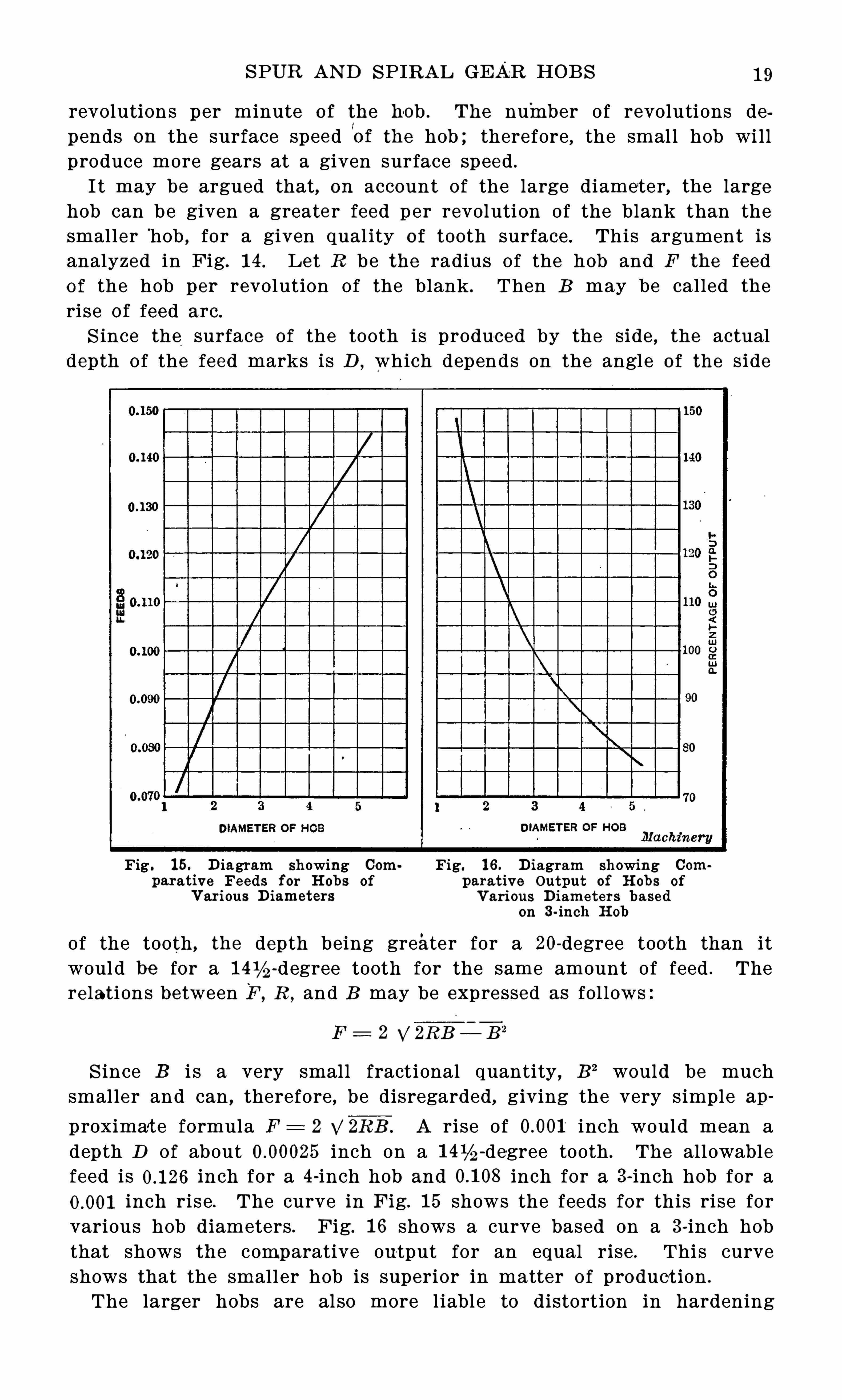
Fig . 1 5. D iagram showing Com Fig. 1 6 . D iagram showing Comparat ive Feeds for H obs of parat ive Output Of H obs of
V ari ous D iameters V ari ous D iameters basedon 3-inch H ob
of the tooth, the depth being greater for a 20-degree tooth than itwoul d be for a -degree tooth for the same amount of feed . Therelations between F , R ,
and B may be expressed as fol lows
F = 2 %%Z R E—B 2
S ince B i s a very small fractional quantity , B 2 would be muchsmaller and can , therefore , be disregarded, giving the very simple ap
proximat e formula F 2 2 V 2R B . A rise Of inch would mean adepth D of about inch on a -degree tooth . The allowablefeed is inch for a 4 -inch hob and inch for a 3-inch hob for a
inch rise . The curve in Fig. 1 5 shows the feeds for this rise forvarious hob diameters . Fig. 1 6 shows a curve based on a 3-inch hobthat shows the comparative output for an equal rise . This curve
shows that the small er hob is superior in matter of product ion .
The larger hobs are al so more l iable to distort ion in hardening
20 N O. 1 33 —HOB S AN D GEAR HOB B IN G
and they do not clear th emselves as wel l as the small er ones whencut-ting ; consequently , they need a greater amount o f rel ief. Largehobs also require a great er over-run of feed at the start o f the cut .When cutting spiral gears Of large angles this greatly reduces theoutput, as the greater amount of feed required before the hob entersto full depth in the gear is a pure waste .The questi on of whether the gashes or flutes should be parallel
with the axis or at right angles to the thread hel ix has two si des .
From a p ractical point Of view , i t appears to make very l ittl e d ifferencein the results Ob tained in hobs Of smal l p itch and angl e o f thread .
In hobs Of coarse p itch, however , the gashes should undoubtedly benormal to the thread . The effect o f the straight gash i s noticed whencutting steel , in that i t i s difli -cult to Obtain a smooth surface on one
side O f the tooth , especial ly when cutting gears coarser than 1 0 p itch .
What has been said in the foregoing, however, app l ies equally tostraight and sp iral ly fluted hobs .
22 N O. 1 33— HOB S AN D GEAR HOB B ING
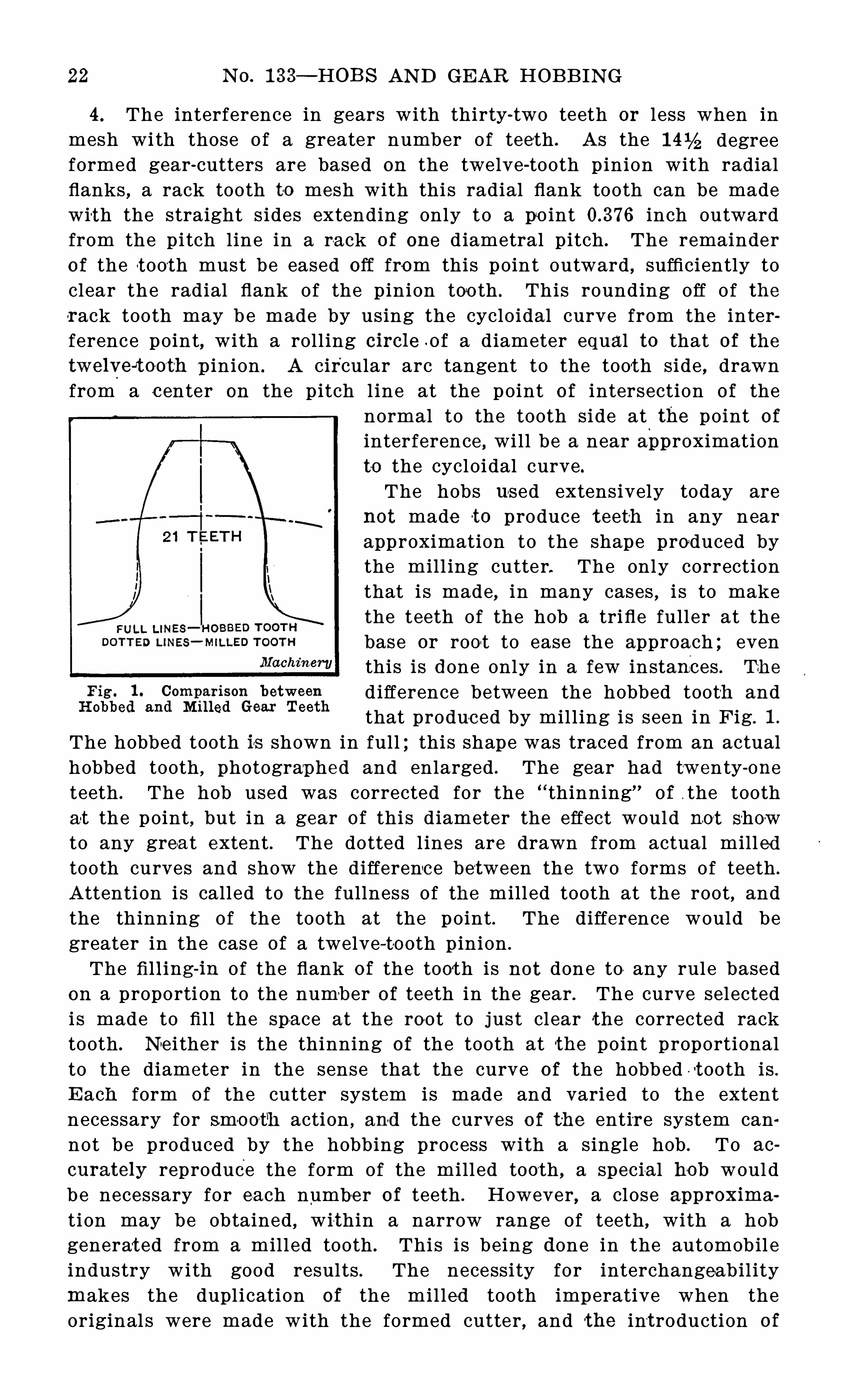
4 . The interference in gears with thirty-two teeth or l ess when inmesh with those Of a greater number Of teeth . As the 1 4 1743 degreeformed gear-cutters are based on the twelve-tooth pinion with radialflanks , a rack tooth to mesh with thi s radial flank tooth can be madewith the straight s ides extending only to a po int inch outwardfrom the pitch line in a ra ck o f one diametral pitch . The remaindero f the t ooth must be eased off from this point outward , sufficiently toclear the radial flank Of the pinion tooth . This rounding Off O f th erack tooth may be made by using the cycloidal curve from the interference point, with a roll ing circle o f a diameter equal to that Of thetwelveJtooth p inion . A circular arc tangent to the tooth side , drawnfrom a center on the pitch l ine at the point of intersection of the
normal to the tooth side at the point of
interference , will be a near approximationto the cycloidal curve.The hobs used extensively today are
not made to produce t eeth in any nearapproximation to the shape produced bythe mill ing cutter. The only correctionthat i s made, in many cases , i s to makethe teeth of the hob a trifle fuller at thebase or root to ease the approach ; eventhis is done only in a few instances . The
F ig. 1 . Comparison between difference between the hobbed tooth andR obbed and M ined Gear Teeth
that produc ed by mil l ing i s seen in Fig. 1 .
The hobbed tooth is shown in full ; this shape was traced from an actualhobbed tooth , photographed and enlarged . The gear had twenty-one
teeth . The hob used was corrected for the thinning% of the toothat the point , but in a gear o f thi s diameter the effect would no t showto any grea t extent . The dotted l ines are drawn from actual mill edtooth curves and show the differenc e between the two forms of teeth .
Attention i s called to the fullness Of the mill ed tooth at the root, andthe thinning Of the tooth at the point . The difference would begreater in the case of a twelve-to oth pinion .
The filling-in Of the flank o f the tooth is not done to any rule basedon a proporti on to the numb er o f teeth in the gear . The curve selectedi s made to fi l l the spa ce at the root to just clear the corrected racktooth . N ei ther is the thinning of the tooth at the point proportionalto the diameter in the sense that the curve of the hobbed - t ooth is .
E ach form o f the cutter system is made and varied to the extentnecessary for smo oth action , and the curves o f th e entire system cannot be produced by the hobbing process with a single hob . To ac
curately reproduce the form Of the mill ed tooth , a specia l hob wouldbe necessary for each number of teeth . However, a close approx ima
ti on may be obtained , within a narrow range Of teeth , with a hobgenerat ed from a mill ed tooth . This is being done in the automobil eindustry with good results . The necessity for interchangeabil itymakes the dupl ication of the mil led tooth imperative when theoriginal s were made with the formed cutter , and the int roduction o f
SPE CIAL HOB S 23
the hobbing machine, in such cases , depends on the successful dupl ication of these forms . I t is no exceptional thing to see the hobbingprocess used in conjunction iv ith the automat ic gear—cutter in theproduction of interchangeable transmission and timing gears . Theshapes produced by the standard s ets Of cutters , from a rack to atwelve-tooth p inion , cannot, however, be generat ed by a single hob ,because the shapes are only an approxima tion of the correct curve .
The gears mentioned above as being successfully hobbed are, therefore, when mil led , cut with sp ecial cutters for each number o f teeth ,as in this way only can a curve of correct shape be Ob tained .
As stated above , mos t hob s are Of the straight-sided sh ape, andthe tooth hobbed is O f pure involute form . In gears of less than
thirty-two teeth, the flank is undercut to a considerable extent . Thisundercutting does not involve any incorrect action in the roll ing of
the gears , but in the case of the twelve-tooth gear , for example , the
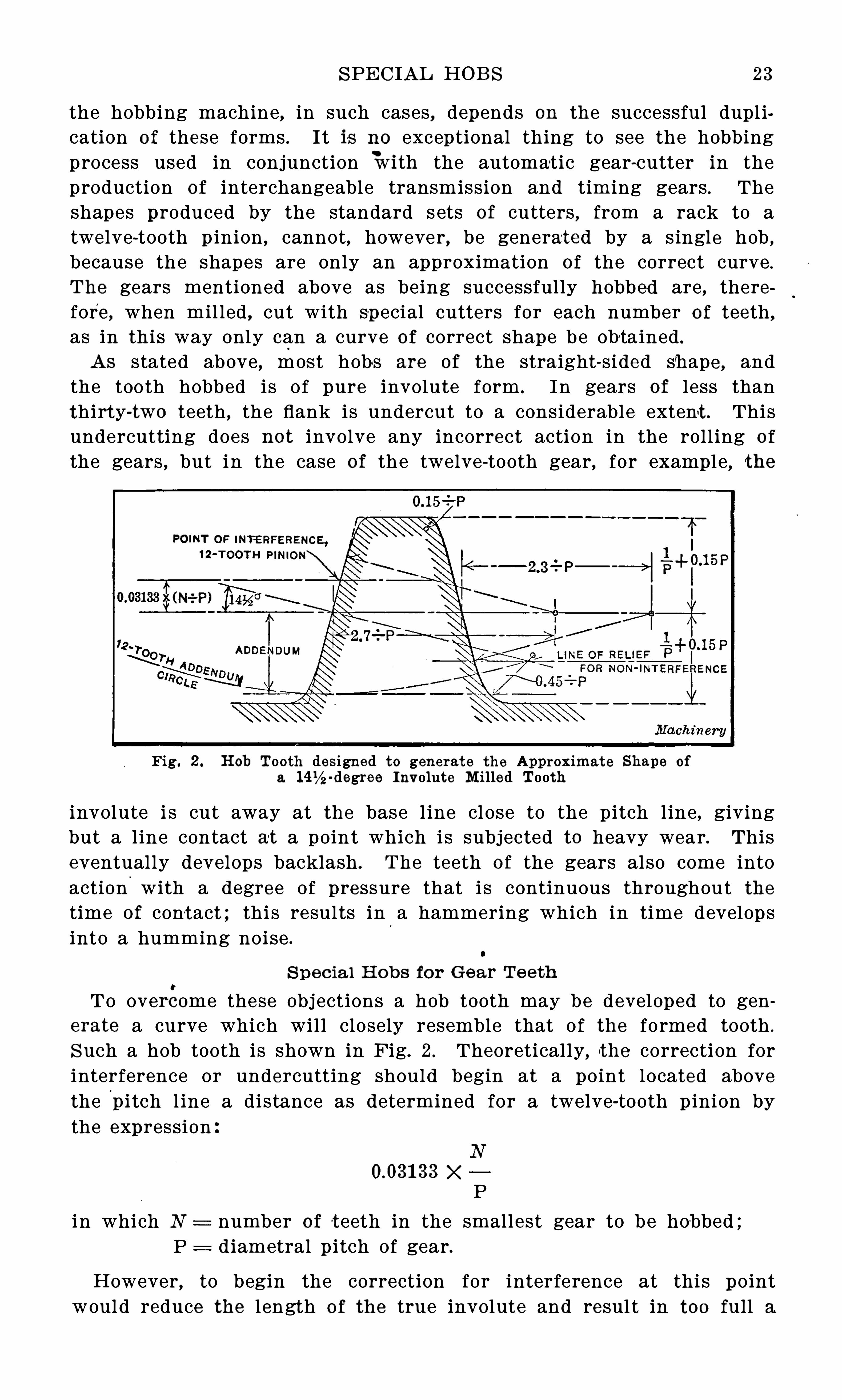
Fig. 2 . H ob Tooth designed to generate the Approx imate Shape Of
a -degree Involute M illed Tooth
involute i s cut away at the base l ine cl ose to the pitch l ine , givingbut a l ine contact at a point which is subjected to heavy wear. Thiseventually develops backlash . The teeth o f the gears also come intoaction
.
with a degree of pressure that i s continuous throughout thetime of contact ; thi s resul ts in a hammering which in time developsinto a humming noise .
S pec ia l H ob s for Gear Te eth
To overcome these obj ections a hob tooth may be developed to generate a curve which will closely resemble that of the formed tooth .
S uch a hob tooth is shown in Fig. 2 . Theoretically, the correction forinterference or undercutting should begin at a point located abovethe pi tch l ine a distance as determined for a twelve-tooth pinion bythe expression
XP
in which N number of t eeth in the smallest gear to be hobbed ;P diametral pitch of gear.
However,to begin the correction for interference at this point
would reduce the length of the true involute and resul t in too full a

24 N O. 1 33— HOB S AN D GEAR HOB B ING
tooth , causing noisy gears . Therefore, a compromise is made andthe correction is Obtained for a minimum of twenty-one teeth . Tocompensate for th e extra fullness of the tooth at the root, the pointof the tooth is thinned down in proportion , and this is done by leavingthe tooth of the hob ful l below the pitch l ine by striking an are froma center on the p itch l ine , and also employing a large fi l l et having aradius equal to 04 5 —P ( see Fig. I t wil l be noticed that theradius o f the are at the top o f the hob tooth is smaller than the radiusat the bottom o f the hob tooth . This Wi l l thin the t ooth of the gearin excess of the amount necessary to clear the flank , easing the actionand el iminating the hammering effect due to the theoretical contact.I t wi ll be seen from the i l lustrat ion that the thinning O f the teeth doesnot affect the twelve-tooth gear to any appreciable extent, but isgradual ly increased with the number o f teeth . The fact that a twelvetoot h gear will mesh without interference at the point of the teeth
Fig. 3 . H ob’
Tooth for generating a 20-degree Involute M illed Tooth
makes the thinning unnecessary ; bes ides , the small p inions are usuallyth e drivers .
Fig. 3 shows a twenty-degree hob tooth with standard ad dendum andcorrections for non-interference . The curve of the tooth begins at ap oint inch from the pitch l ine , in the case of a one diametralp itch toot h , and i s based on non-interference w i th all teeth fromtwelve teeth up .
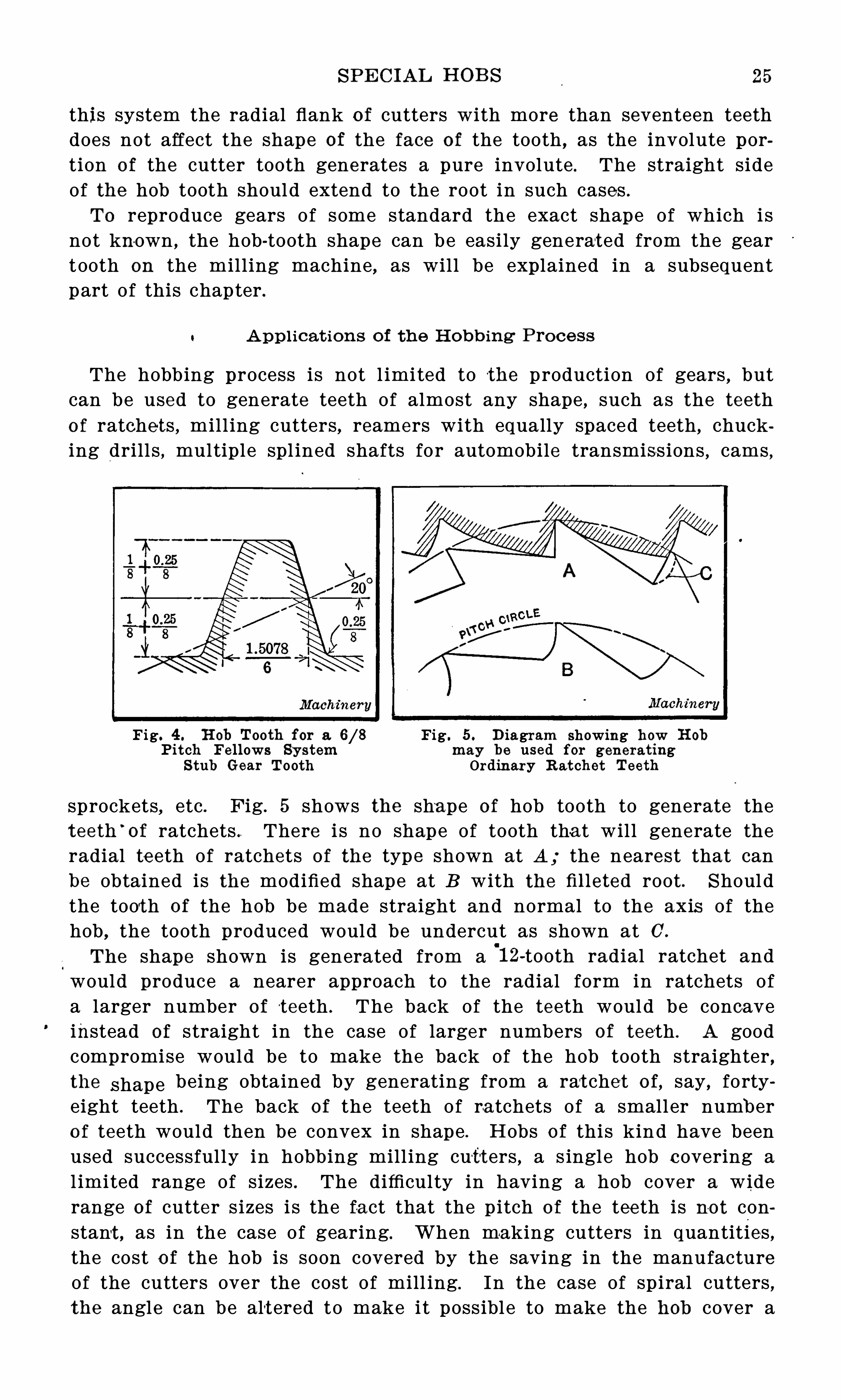
Fig. 4 shows the shape Of the hob tooth to reproduce the stub teeth
o f the gears generat ed on the Fell ows gear shaper . The particulartooth in the figure is a p itch tooth , and the proporti ons are givenin terms Of the p itch numbers so as to be easily appl ied to
'
the o therp i tches ; thus the height of the tooth above the p itch l ine i s stated as
where 8 i s the addendum number o f. the p itch des ignat ion .
8
The shape of the rack or hob tooth to roll with the gears p roducedby the gear shaper should be generated from the cutter used . TheFellows cutters have perfect involutes above the base line , with radialflanks , so that the hob tooth would be straight only a distance fromthe pi tch l ine equal to X N —:i P , where N i s the number o f teethin the cut ter ; in most cases the cutter would have more than s eventeen teeth and the hob tooth would be straight-sided to the point . In
SPE C I AL HOB S
this system the radial flank o f cutters with more than seventeen teethdoes not affect the shape of the face o f the tooth , as the involute portion o f the cutter tooth generates a pure involute . The straight sideof the hob tooth should extend to the root in such cases .
To reproduce gears of some standard the exact shape of which i snot known , the hob-tooth shape can be easily generated from the geartooth on the mill ing machine, as will be explained in a subsequentpart o f this chapter .
A ppl icat ion s o f th e H ob b ing Pro ce ss
The hobbing process is not l imited to the production of gears,but
can be used to generate teeth of almost any shape , such as the teetho f ratchets , mill ing cutters, reamers with equally spaced teeth
,chuck
ing drill s , multiple spl ined shafts fo r automobile transmissions , cams ,
Fig. 4 . H ob Tooth for a Fig. 5 . D iagram showing how H ob
Pit ch Fe llows Sy stem may be used for generat i ngS tub Gear Tooth Ordinary R at chet Teeth
sprockets,etc . Fig. 5 shows the shape of hob tooth to generate the
teeth‘
of ratchets . There i s no shape of tooth tha t wil l generate theradial te eth of ratchets of the type shown at A ; the nearest that can
be obtained is the modified shape at B with the filleted root . Shouldthe tooth of the hob be made straight and normal to the axis of thehob , the tooth produced would be undercut as shown at C’.The shape shown is generated from a
'
1 2-tooth radial ratchet andwould produce a nearer approach to the radial form in ratchets o fa larger number of t eeth . The back of the teeth would be concaveinstead of straight in the case of larger numbers of teeth . A goodcompromise would be to make the back of the hob tooth straighter ,the
.shape being obtained by generating from a rat che t o f, say, fortyeight teeth . The back of the teeth of ra tchets of a small er numb ero f teeth would then be convex in shape . Hobs o f this kind have beenused successfully in hobbing mill ing cutt ers , a s ingle hob covering al imi ted range of sizes . The difficulty in having a hob cover a widerange of cutter s izes i s the fa ct that the pitch of the tee th is no t constant , as in the case of gearing. When making cutters in quantities ,the cost o f the hob is soon covered by the saving in the manufactureof the cutters over the cost o f mill ing. In the case of spiral cutters ,the angle can be alt ered to make it possibl e to make the hob cover a
26 N O. 1 33— HOB S AN D GEAR HOB B ING
greater range o f s izes . The hobb ing process is especial ly. adapted tothe making of spiral mill ing cutters .
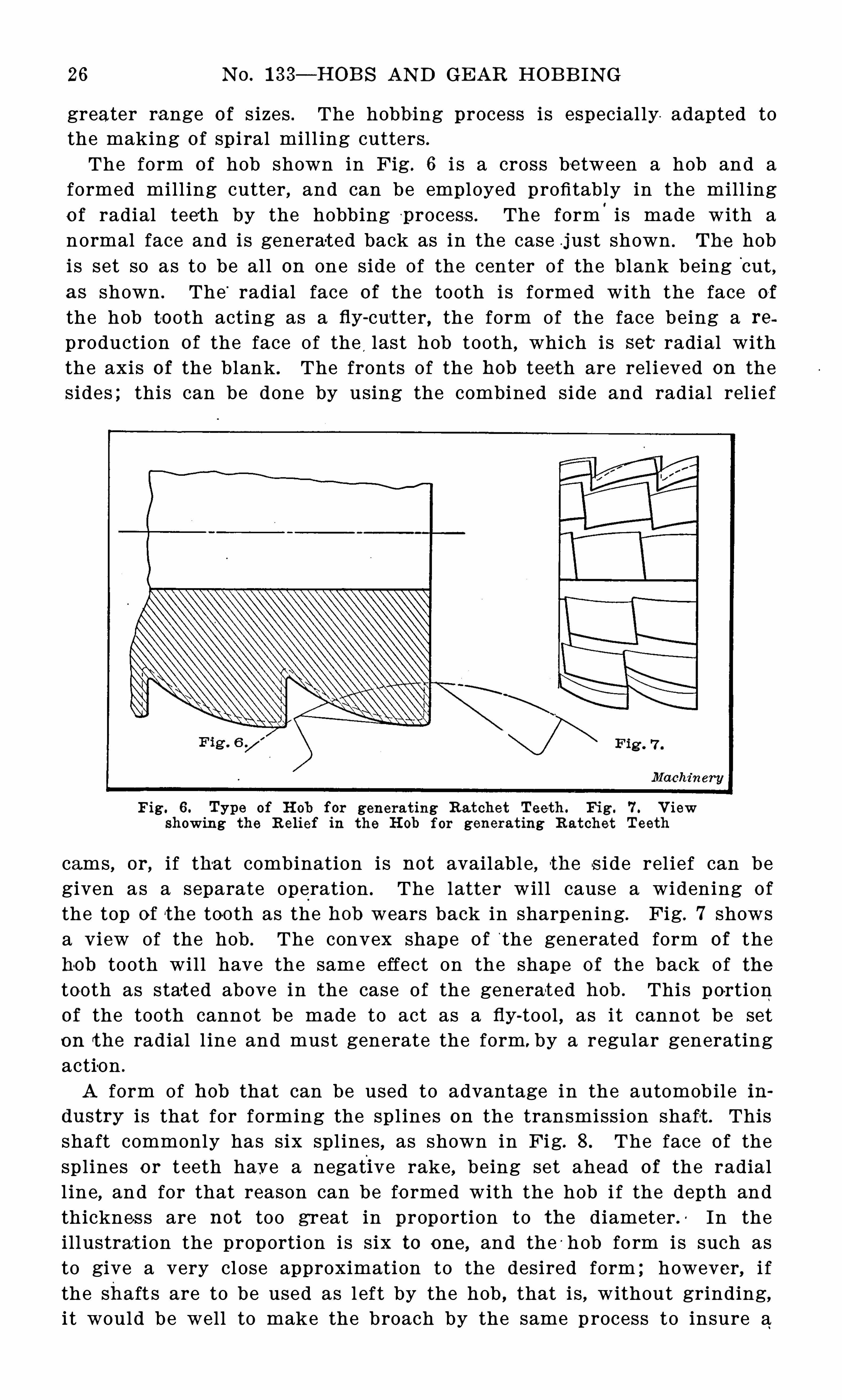
The form o f hob shown in Fig . 6 i s a cross be tween a hob and aformed mill ing cutter , and can be employed profitably in the mill ingo f radial teeth by the hobbing p rocess . The form
'
i s made with anormal face and is genera-ted back as in the case just shown . The hobis set so as to be al l on one side of the center of the blank being
‘
cut,
as shown . The“
radial face of the tooth is formed with the face of
the hob to oth acting as a fly -cut ter, the form of the face being a re
production of the face of the last hob tooth , which is set radial withthe axis of the blank . The fronts of the hob teeth are rel i eved on thesides ; this can be done by using the combined side and radial rel ie f
Fig. 6 . Type of H ob for generat ing Ra tchet Teeth . F ig. 7 . V iewshowing the R elief in the H ob for generat ing R atchet Teeth
cams , or, if that combination is not availabl e , the s i de rel ief can begiven as a separate operation . The latter wil l cause a widening of
the top of the too th as the hob wears back in sharpening. Fig. 7 showsa V iew of the hob . The convex shape of
‘
the generated form of thehob tooth will have the same effect on the shape o f the back of thetoo th as stat ed above in the case of the generat ed hob . This por tionof the tooth cannot be made to act as a fly
-tool , as i t cannot be seton the radial l ine and must generate the form. by a regular generatingactio n .
A form of hob that can be used to advantage in the automob il e industry i s that for forming the spl ines on the transmission shaft . Thisshaft commonly has six spl ines , as shown in Fig. 8 . The face of thesplines or teeth have a negative rake , being set ahead of the radiall ine, and for that reason can be fo rmed with the hob i f the depth andthickness are not too great in proportion to the diameter . In theillustration the proportion is six to one , and the -hob form is such asto give a very close approximation to the desired form ; however, i fthe shaft s are to be used as l eft by the hob , that is , without grinding,i t would be well to make the broach by the same p rocess to insure a
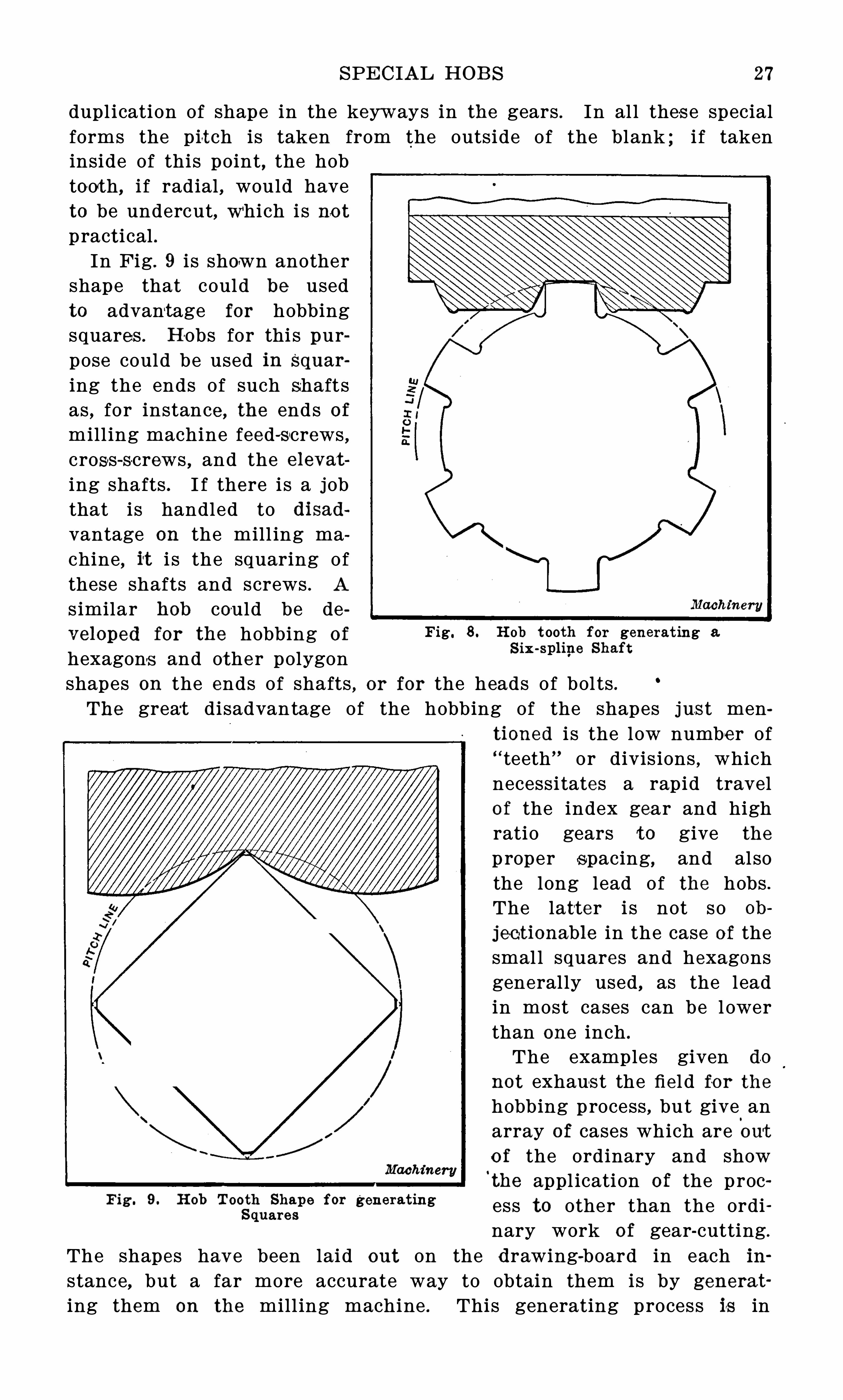
SPE CIAL HOB S 27
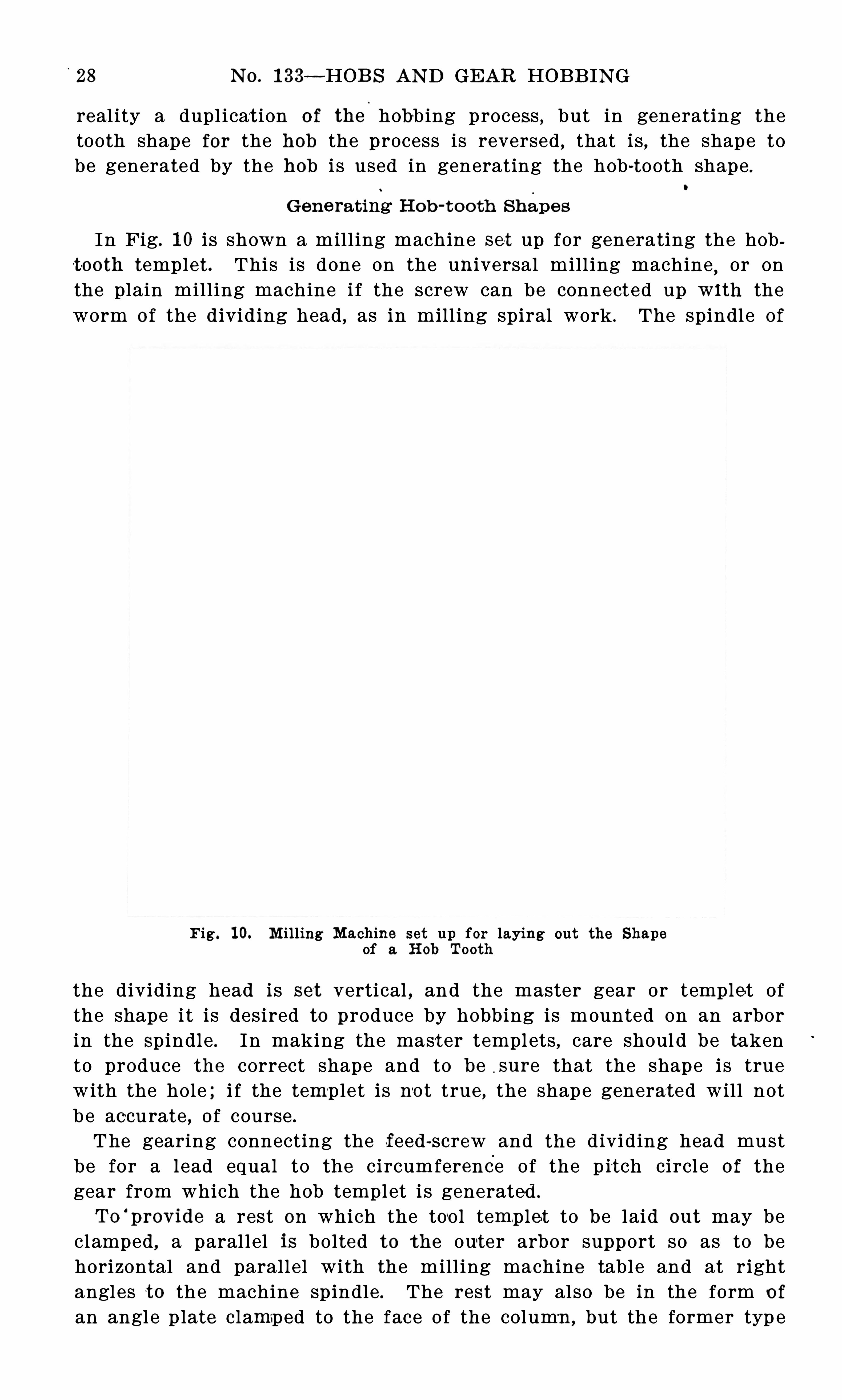
dupl ication of shape in the keyways in the gears . In al l these specialforms the pit ch is taken from the outside of the blank ; i f takeninside of this point , the hobtooth, i f radial , would haveto be undercut, which i s no tpract ical .In Fig . 9 i s shown another
shape that could be usedto advantage for hobbingsquares . H obs for thi s purpose could be used in Squar
ing the ends of such shaftsas , for instance , the ends ofmill ing machine feed-screws ,cross-screws , and the elevat
ing shafts . I f there is a jobthat is handled to disad
vantage on the mill ing machine, it i s the squaring ofthese shafts and screws . A
s imilar hob could be developed for the hobbing Of Fig. 8 . H ob t ooth for generat ing a
S ix -spline Shafthexagons and other polygonshapes on the ends of shafts , or for the heads of bol ts .The great disadvantage of the hobbing of the shapes jus t men
tioned i s the low number of“ teeth% or divis ions , whichnecessitates a rapid travelof the index gear and highratio gears to give the
p roper spacing, and alsothe long lead of the hobs .
The latter i s not so ob
jectionable in the case of thesmal l squares and hexagonsgenerally used , as the leadin most cases can be l owerthan one inch .
The examples given do
not exhaus t the fiel d fo r thehobbing process , but give
.
anarray of cases which are out
o f the ordinary and showt he appl ication o f the proc
F ig ' 9° H °b f% generat ing ess to other than the ordinary work o f gear-cutting.
The shapes have been laid out on the drawing-board in each ih
stance,but a far more accurate way to obtain them is by generat
ing them on the mill ing machine . This generating process is in
'
28 N O. 1 33 —HOB S AN D GEAR HOB B IN G
real ity a dupl icat i on o f the hobbing process , but in generating thetooth shape for the hob the process is reversed , that is , the shape tobe generated by the hob i s used in generating the hob-tooth shape
.
Gene rat ing H ob -t o o th Shape s
In Fig. 1 0 i s shown a mill ing machine set up for generating the hobt-ooth temp l et . This is done on the universal mill ing machine or onthe plain mill ing machine i f the screw can be connected up w1 th theworm o f the dividing head, as in mill ing spiral work . The spindle of
Fig . 1 0. M illing Machine set up for laying out the Shapeof a H ob Tooth
the dividing head is set vertical , and the master gear or temple t ofthe shape i t is desired to produce by hobbing is mounted on an arborin the Spindle . In making the mast er templets , care shoul d be takento produce the correct shape and to be sure that the shape is truewith the hole ; i f the templet is no t true , the shape generated will notb e accurate , of course .
The gearing connecting the feed-screw and the dividing head mustbe for a l ead equal to the circumference of the p it ch circl e o f thegear from which the hob templet i s generated .
To‘
prov ide a rest on which the tool templet to be laid out may beclamped , a paral lel is bolted to the out er arbor support so as to behorizontal and parall el with the mill ing machine table and at rightangles to the machine spindle . The rest may also be in the form o f
an angl e p late clamped to the face of the column , but the former typ e
30 N O. 1 33— HOB S AN D GEAR HOB B IN G
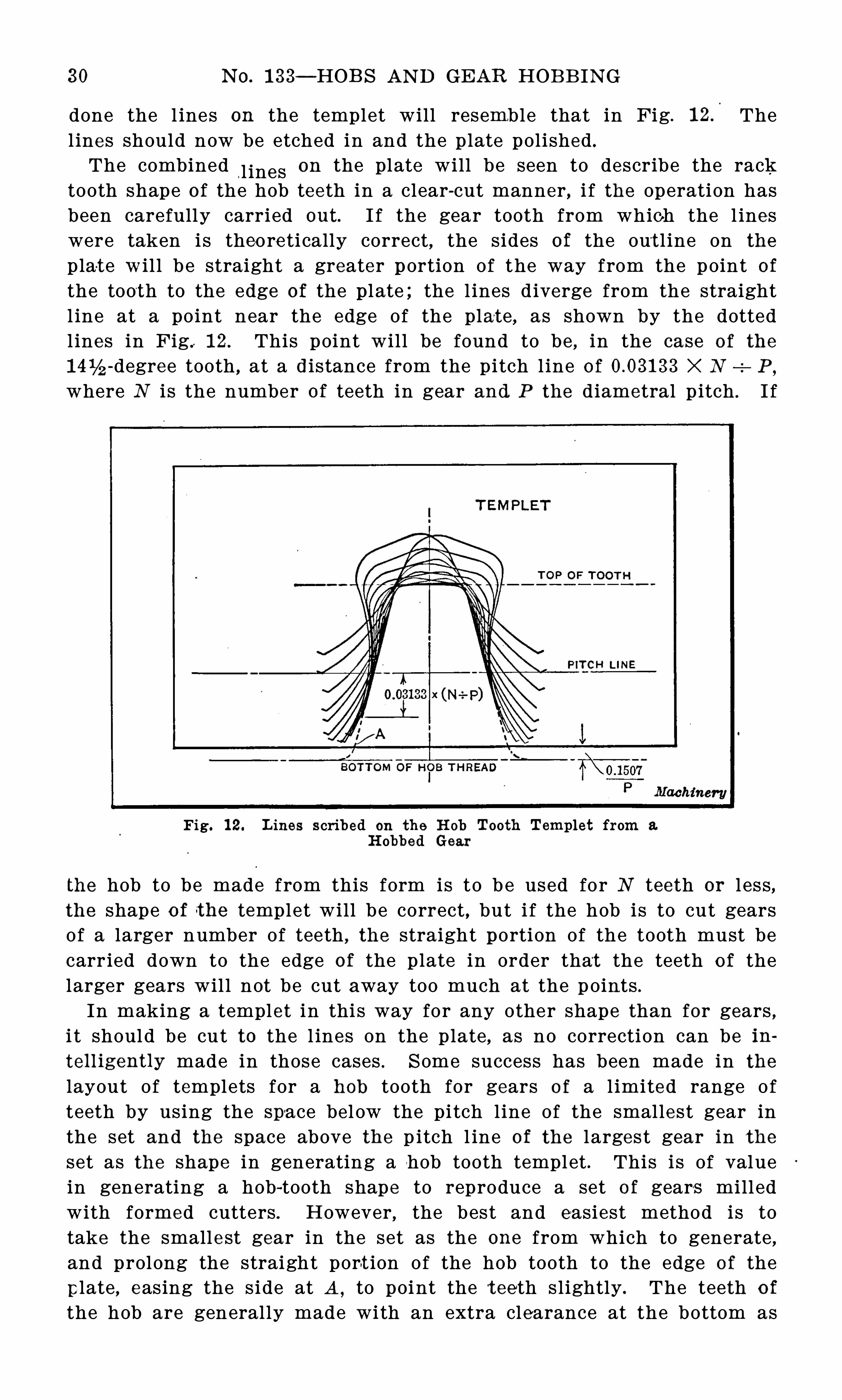
done the l ines on the templet will resemble that in Fig. Thel ines should now be etched in and the plate polished .
The combined“l ines on the plate will be seen to describe the rac%
tooth shape o f the hob teeth in a clear-cut manner , i f the operation hasbeen carefully carried out. I f the gear tooth from which the l ineswere taken i s theore ti cally correct, the sides of the out l ine on the
plat e wi l l b e straight a greater portion of the way from the point of
the tooth to the edge of the p l ate ; the l ines d iverge from the straightl ine at a point near the edge of the plate, as shown by the dottedl ines in Fig. 1 2. This point wil l be found to be , in the case o f the
-degree tooth , at a distance from the pitch l ine o f X N P,
where N i s the number of teeth in gear and P the diametral p itch . I f
Fig. 1 2. L ines scribed on the H ob Tooth Templet from a.
H obbed Gear
the hob to be made from this form is to b e used for N teeth or l ess,the shape o f the templet will b e correct , but i f the hob is to cut gearsof a larger number of teeth , the straight portion of the tooth must becarr ied down to the edge of the plate in order that the teeth o f thelarger gears wil l not be cut away too much at the p oints .In making a templet in thi s way for any other shape than for gears ,
i t should be cut to the l ines on the plate , as no correction can be in
telligently made in those cases . S ome success has been made in the
layout of templets for a hob tooth for gears o f a l imited range o fteeth by using the space be l ow the pi tch l ine of the smallest gear inthe set and the space above the p itch l ine of the l arges t gear in theset as the shape in generating a hob tooth templet . This is of valuein generating a hob-tooth shape to reproduce a set o f gear-s mill edwith formed cutters . However, the best and easiest method is totake the smalle st gear in the set as the one from which to generate ,and prolong the straight port ion of the hob tooth to the edge of the
plate , easing the s ide at A , to point the t eeth s lightly . The teeth o f
the hob are generally made with an extra clearance at the bottom as
SPE CIAL HOB S 31
shown . This is a matter on wh i ch authorities differ , some preferringto have the hob cut the top o f the teeth , to make the teet h of standardl ength i f the blanks shoul d be over size ; however , the general practice is to make the tooth the same length both above and below the
p itch l ine as in Figs . 2 and 3.
I f the form is for a generated gear and results in the straigh t-sidedtool in Fig . 1 2, al l that is necessary i s to measure the angl e and makea thread tool
-
that wil l cut a thread of this section . Should the shape
t urn out to be a compound of curves , as will b e the case in repro
ducing the milled tooth, the temple t sho uld be fi led out to the l ines ,making a female gage to which a planing tool is made , the planingtool be ing a dupl icate o f the hob-t ooth shape . The threading tool i sp laned up with this tool . In making the thread tool , i t i s not usualto make it o f female shape , that is , l ike the templet , but pointed asusual , planing the sides with the oppos ite sides of the planing tool .The proper corrections should be made in the thread tool to correspond to the angle of the thread , and the setting of the tool andthe fluting o f the hob , whether i t i s gashed parallel to the axis ornormal to the thread hel ix .
Ma% ing a Mast e r Plan ing To o l fo r a H o b
A master planing tool can be made in the fol lowing manner, without the use of the scribed l ine templet . I t is necessary to have auniversa l mil l ing attachment for the mill ing machine . The spindleof the attachment is set in the horizontal posit ion with the axisparallel with the direct i on o f the table movement . A fly
-tool holderi s then p laced in the sp indle , in which the blank planing tool i s tobe held . This tool should be roughly formed to the shape to whichi t i s to b e finished . The top of the tool should be radial , that is , i tshould be in the plane of the center o f the spindle . The gear or othermaster templet that i t i s desired to dupl icate by hobbing must behardened and ground to a cutting edge on one face, preferably thetop face when mounted in the spindle o f the dividing head , so that thepressure o f the cut will be downwa rd . The knee shoul d be adjustedto bring the ground face of the gear to the level o f the cent er of thespindle of the attachment. The dividing head and the table screware connected in the
'
same way as previously described , but in thiscase the power feed can be used and the saddle can be fed in to depthas needed, care being taken to use the power feed , in generating thetool , only in one direction , as the backlash in the gears and screwwil l throw the tool and dividing head out of rela tive position i f usedin the opposite direction . As many cuts can be taken as required toobtain a tool of the correct shape .
I f the tool i s to be used in making more than one threading tool ,as might be the case in many instances, the planing too l can be madein the shape of a circular tool which can be ground indefinitely without l osing the shape . In this case the fly -tool holder would give placeto the standard mill ing ma chine arbor . This method is the most ac
32 N O. 1 33— HOB S AN D GEAR HOB B ING
cura te way of making the master p laning tool , and where theuniversal mil l ing attachment is available, i t should be used whereaccurate results are desired . I t el iminates the human el ement andthe amount of skil l required in making the master templet . Theinaccuracy of the ma chine is the only el ement that is l ikely to causee rror.One point that is l ikely to cause difficul ty is the relation of the
generated tool shape to the thread shape, as i t appears in the normalsection of the hob tooth . The simple fact is that the master toolshape , as generated by the direct method of making the master p laning tool , or the shape as outl ined on the hob tooth templ et in the
first method, i s the shape of the cross-section of the,hob thread on a
p lane normal to the hob thread hel ix . This relati on should be kep tin mind throughout the process of making the tools and hob . Thi sstatement also clears any haziness regarding the question of the l ead,as in single-threaded hobs this must be such that the normal p itchof the thread is equal to the circular p itch o f the teeth hobbed . Inthe case of hobs of small thread angles, the normal and axial leads arepractically the same, and may be treated as such in cases where theangle i s l ess than 2 degrees and the p itch less than lé inch ; an errorof more than inch should not be exceeded in any case. Thee ffect o f the error is apparent in the case of a 6 diametral p itch hob3 inches in diameter, when the axial l ead is taken as the cirottiar
pitch of the teeth , as it resul ts in an error of more than one ehalf
degree in the pressure angl e of the hobbed tooth . Only in extremecases should the ang le of the hob thread be more than ten degrees .Hobs wi th greater angles than this are diffiCult to make and use . Inhobs of l ong lead the diameter should be proportioned so as to obtaina reasonable angl e of thread . However, the extreme in d iameters isas bad as the steep angles, and in cases where the two extremes aremet a compromise i s the only solution .
The method used in laying out the tooth shapes on the drawingboard i s an interesting study , but the method of generating the toolas described i s the most useful , and can be rel ied on fo r accurateresults ; th i s is not the case with the drawing-board method whichis of value only as a means of getting an approximate shape .
CHAPTE R I II
THE CE N TER I N G OF TH E H OB I N GEAR HOB B IN G
Whether or not it i s necessary to center the hob in order to getsatis factory results in gear hobbing, i s a question tha t i s not soreadily answered as i t might appear . For the sake of making thematter clea r to those who have not the time to make a study of thesubj ect, the results of an investigation conducted by the writer wil lno doubt be o f interest. Theoretically speaking, there should be nodifference in the resul ts whether the hob is centered or not. However,practical mo difications enter into the actual conditions and exertpecul iar effects upon the results produced . To briefly explain theaction of the hob , we may say that the generating operation consists
Fig. 1 . D iagram showing P oints of Intersect ion of the PressureL ines with the H ob Teeth equally spaced at each
S ide of the Pit ch Point
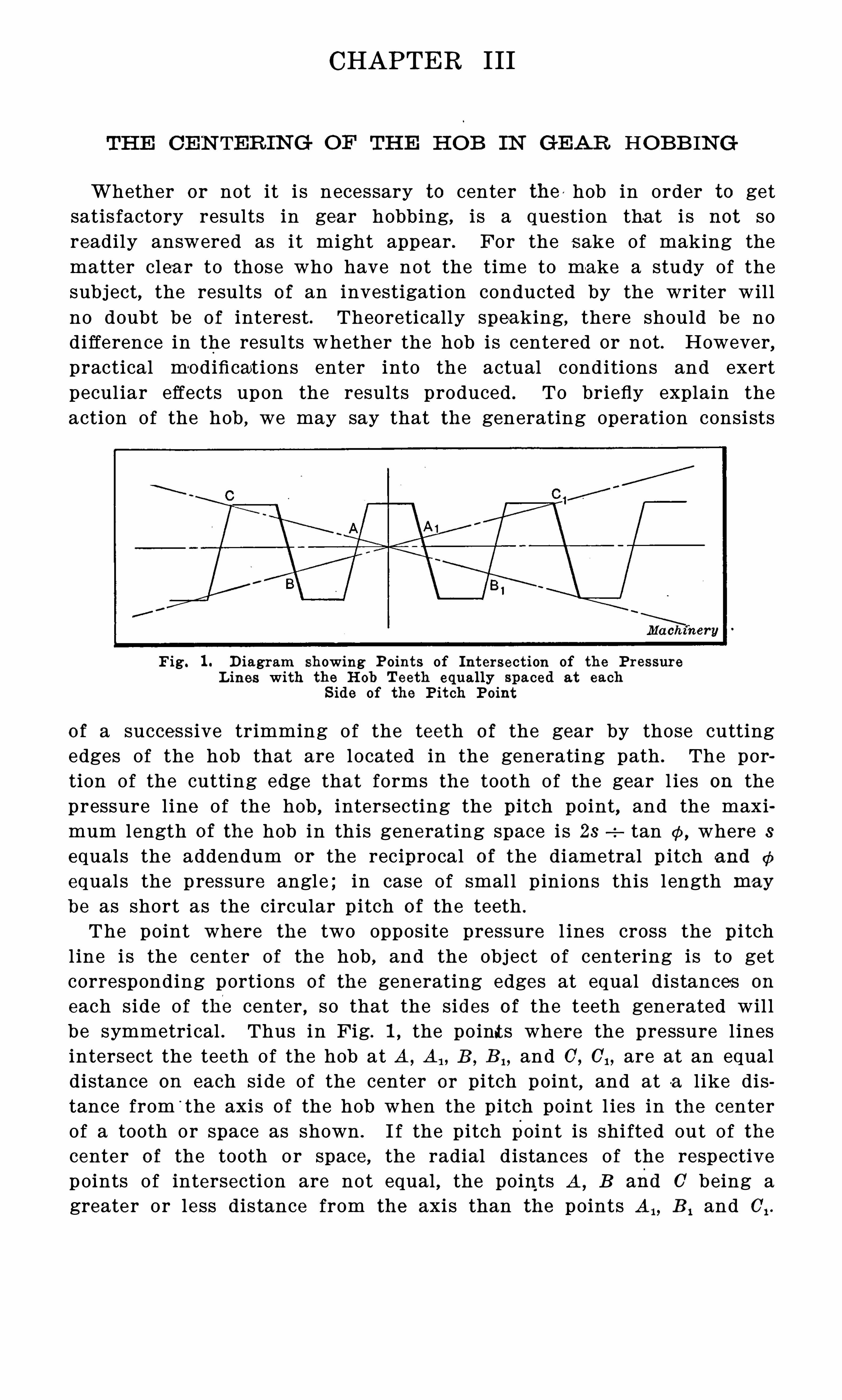
of a successive trimming of the teeth o f the gear by those cuttingedges of the hob that are located in the generating path . The portion of the cutting edge that forms the tooth of the gear l ies on thepressure line of the hob , intersecting the p itch point, and the maximum length of the hob in this generating space i s 23 tan where 3
equals the addendum or the reciprocal o f the diametral p itch and (15
equals the pressure angle ; in case of smal l p inions this l ength maybe as short as the circular p itch of the teeth .
The point where the two opposite pressure l ines cross the p i tchl ine i s the center of the hob , and the obj ect o f centering is to getcorresponding portions of the generating edges at equal distances on
each side of the center , so that the sides o f the teeth generated wil lbe symmetrical . Thus in Fig. 1 , the point s where the pressure l inesintersect the teeth of the hob at A , A B
, B , , and 0 , 0 1 , are at an equaldistance on each side of the center or pitch point, and at a l ike distance from
'
the axis o f the hob when the pitch point l ies in the centerof a tooth or space as shown . I f the pitch point is shi fted out of thecenter of the tooth or space , the radial distances o f the respectivepoints o f intersection are not equal , the points A ,
B and 0 being agreater or less distance from the axis than the points A B 1 and C, .
34 N O. 1 33— HOB S AN D GEAR HOB BI N G
There are defects in the hob that cannot be compensated for by anyamount of centeri ng, and the generating of symmetrical teeth cannotbe insured . Among these we may cite the defects due to distortionin harden ing, unequal tooth thickness due to springing of the toolin forming, and errors in s ize resul ting from careless workmanship .
The defect that can be favored in the setting of the hob is that inwhich the eccentricity of the form ana x is causes the teeth to runout. This eccentrici ty may be caused by the use of an inaccura temandrel in the backing-off operation or by not truing up the hobproperly in grinding the hole ; i t may also be caused by an untruehob arbor on the hobbing machine i tsel f. These defects can be determined and proper all owance made to counteract the natural resultsby a careful setting of the hob . B y knowing what resul t wil l beobtained with these eccentric hob conditions the defect can be
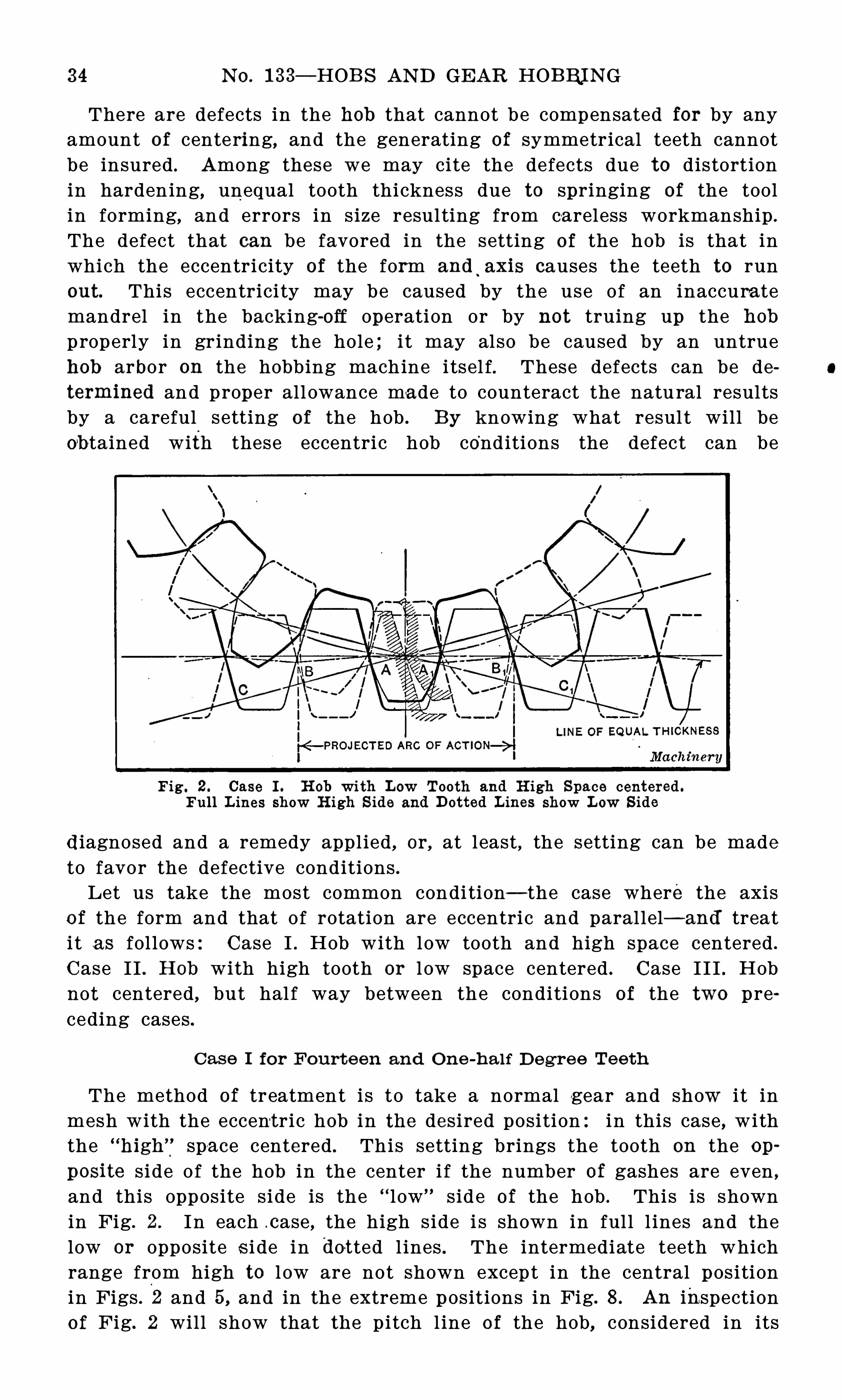
Fig. 2 . Case I . H ob with Low Tooth and H igh Space centered .Full L ines show H igh S ide and Dotted L ines show L ow S ide
diagnosed and a remedy appl ied , or, at least , the setting can be made
to favor the defective conditions .Let us take the most common condi tion— the case where the axis
o f the form and that of rotation are eccentric and paral lel— and treati t as fol lows:Case I . Hob with low tooth and high space centered .
Case I I . H ob with high tooth or l ow space centered . Case I I I . Hobnot centered , but hal f way between the conditions of the two preceding cases .
Case I for F ourt e en and On e -h a lf D egre e Tee th
The method of treatment is to take a normal gear and show i t inmesh with the eccent ric hob in the desired position:in this case , withthe “
h igh’ f spa ce centered . This setting brings the tooth on the op
posi te side o f the hob in the center i f the number of gashes are even ,
and this opposite side is the “ l ow% sid e of the hob . This is shownin Fig. 2 . In each c ase , the high side i s shown in ful l l ines and thelow or opposite s i de in dot ted l ines . The intermediate teeth whichrange from high to l ow are not shown except in the central pos itionin Figs . 2 and 5, and in the extreme positions in Fig. 8 . An inspectionof Fig. 2 will show that the pitch l ine of the hob, considered in its
CE N TE R IN G TH E HOB 35
relation to the tooth itsel f, does not l ie along a straight l ine pa rallelto the axis of the hob , but on a zigzag l ine that is shown broken . Thisl ine represents the p itch location of the right side of the hob tooth
,
and may be termed the “ l ine of equal tooth thickness . I t wil l havea drop for each pitch
,
l ength of the hob for every convolution of thethread . In real i ty, the l ine instead of being zigzag should be a re
verse curve .
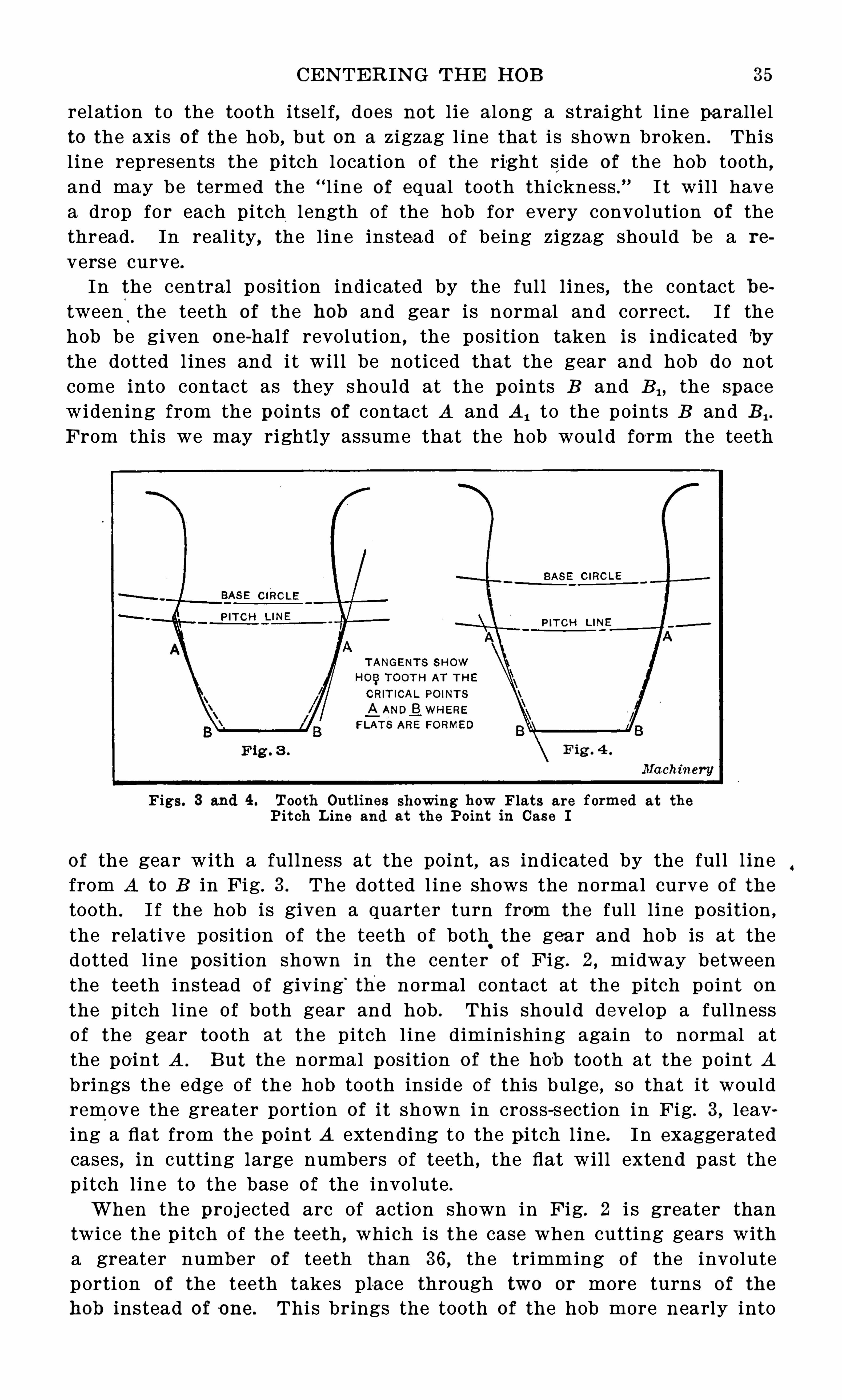
In the central position indicated by the ful l l ines , the contact between%the teeth of the hob and gear is normal and correct. I f thehob be given one-half revolution , the position taken is indicated bythe dotted l ines and it wil l be noticed that the gear and hob do notcome into contact as they should at the points B and B the spacewidening from the points of contact A and AI to the points B and B 1 .
From this we may rightly assume that the hob woul d form the teeth
Figs. 3 and 4 . Tooth Outlines showing how Flats are formed at the
P it ch L ine and at the Point in Case I
of the gear with a fullness at the point,as indicated by the full l ine
from A to B in Fig. 3 . The dotted l ine shows the normal curve of the
tooth . I f the hob is given a quarter turn from the full l ine position ,
the rela tive position of the teeth o f both.
the gear and hob is at thedotted l ine position shown in the center of Fig. 2 , midway betweenthe teeth instead of giving
‘
the normal contact at the pitch point on
the p i tch l ine of both gear and hob . This shoul d develop a fullnessof the gear tooth at the pitch l ine diminishing again to normal atthe po int A . B ut the normal position o f the hob tooth at the point Abrings the edge of the hob tooth inside of this bulge , so that i t wouldremove the greater portion of i t shown in cross-section in Fig. 3, leaving a flat from the point A extending to the pitch l ine . In exaggeratedcases , in cutting large numbers of teeth , the flat will extend past thep itch l ine to the base of the involute .
When the proj ected arc of action shown in Fig. 2 i s greater thantwice the p itch of the teeth , which i s the case when cutting gears witha greater number of teeth than 36 , the trimming of the involuteportion of the teeth takes pla ce through two or more turns of the
hob instead of one. This brings the tooth of the hob more nearly into
4
36 N O. 1 33— HOB S AN D GEAR HOB B IN G
the normal position at the end of the gear tooth, tending to make thepoint of the tooth nearer to the proper thickness ; but the correctthickness i s never reached as i t would be necessary for the contactto continue to the posi tion 0 , which is the case of a gear o f infinitediameter . This develops a flat at the point of the tooth for the samereason as that given for the flat produced at the pi tch l ine . The
result of this action on gears with teeth greater in number than 36
i s i l lustrated in Fig. 4 , where the cross-sectioning shows the excessmetal removed , resulting in the production of the flat. The effect on
the flank of the tooth need not be taken into consideration ; as thehob leaves it , there i s ample clearance for the gear tooth of themating gear , i t being only in the ca se of a gear meshing with a rackthat the flank would be apt to give trouble .
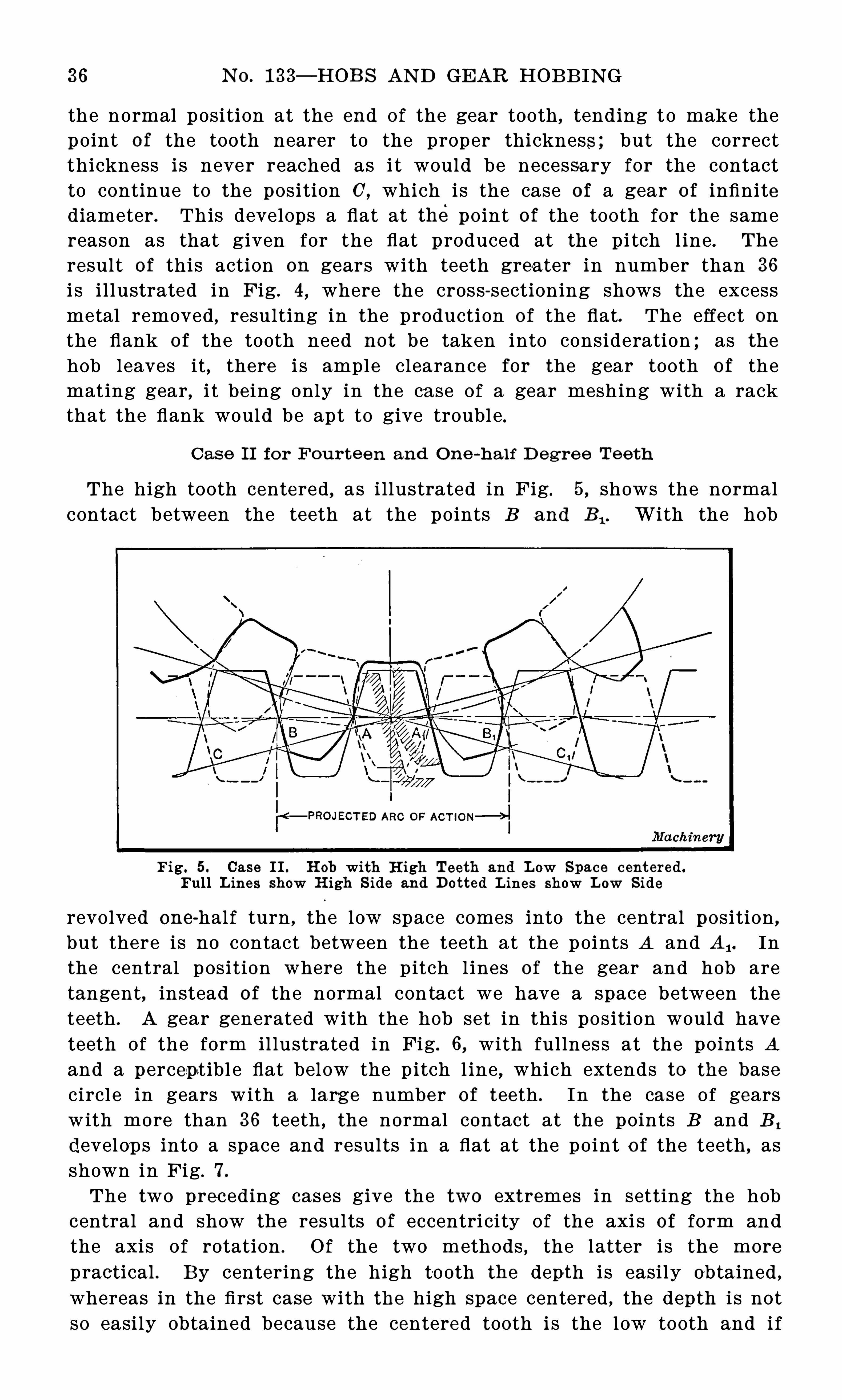
Case I I fo r F ourte en and On e -h a lf D egre e Te e th
The high tooth centered , as i llustrated in Fig. 5, shows the normalcontact between the teeth at the points B and B 1 . With the hob
Fig . 5. Case II . H ob with H igh Teeth and L ow Space centered .
Full L ines show H igh S ide and Dotted L ines show L ow S ide
revolved one-half turn , the low space comes into the central position ,but there is no contact between the teeth at the points A and A, . Inthe central p osition where the p itch l ines of the gear and hob aretangent, instead of the normal con tact we have a space between theteeth . A gear generated with the hob set in this pos ition would haveteeth of the form il lustrated in Fig. 6, with fullness at the points A
and a percept ibl e flat below the p itch l ine , which extends to the basecircl e in gears with a large number of teeth . I n the case of gearswith more than 36 teeth , the normal contact at the points B and B ,
develop s into a space and results in a flat at the point o f the teeth , asshown in Fig. 7.
The two preceding cases give the two extremes in setting the hobcentral and show the resul ts of eccentri city of the axi s of form andthe axis o f rotation . O f the two methods , the latter is the more
practical . B y centering the high to oth the depth is easily obtained ,whereas in the first case with the high space centered , the depth is notso easily obtained because the centered tooth i s the low tooth and i f
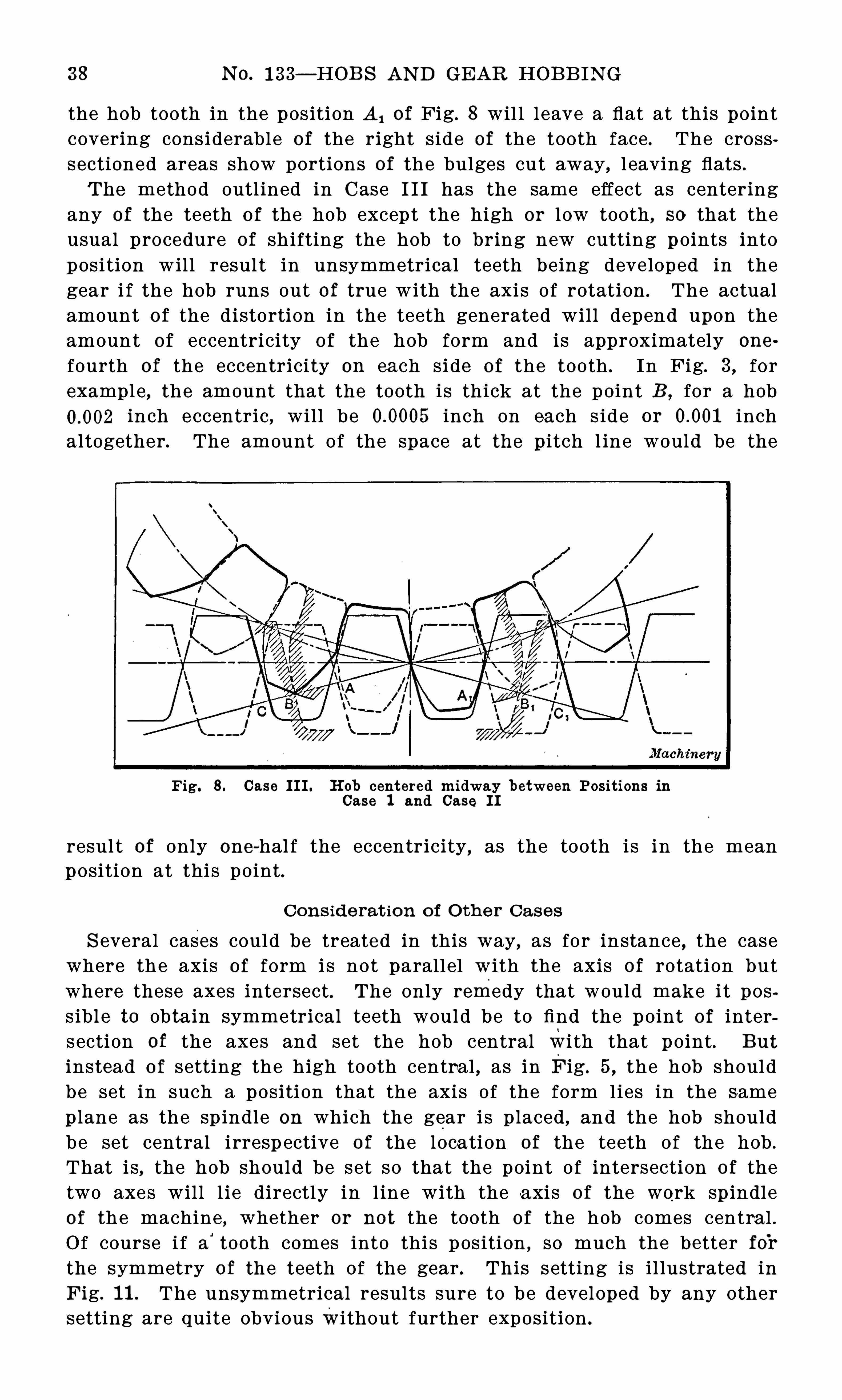
38 N O. 1 33— HOB S AN D GEAR HOB B IN G
the hob tooth in the pos ition A, of Fig. 8 wil l l eave a flat at this pointcovering cons iderable of the right side of the tooth face. The crosssectioned areas show portions of the bulges cut away, l eaving flats .
The method outl ined in Case I I I has the same effect as centeringany of the teeth o f the hob excep t the high or l ow tooth , so that theusual procedure of shifting the hob to bring new cutting p oints intoposi tion will resul t in unsymmetrical teeth being deve loped in thegear i f the hob runs out of true with the axis o f rotation . The actualamount o f the distortion in the teeth generated will depend upon theamount o f eccentricity of the hob form and is approximately one
fourth of the eccentrici ty on ea ch side of the tooth . In Fig. 3, forexample
,the amount that the tooth is thick at the point B , for a hob
inch eccentric,will be inch on ea ch s ide or inch
altogether. The amount of the space at the p itch l ine would be the
Fig. 8. Case III . H ob centered midway between Positi ons inCase 1 and Case 1 1
resul t of only one-hal f the eccentricity, as the tooth is in the meanposition at this point .
Cons id e rat io n o f Oth e r Cases
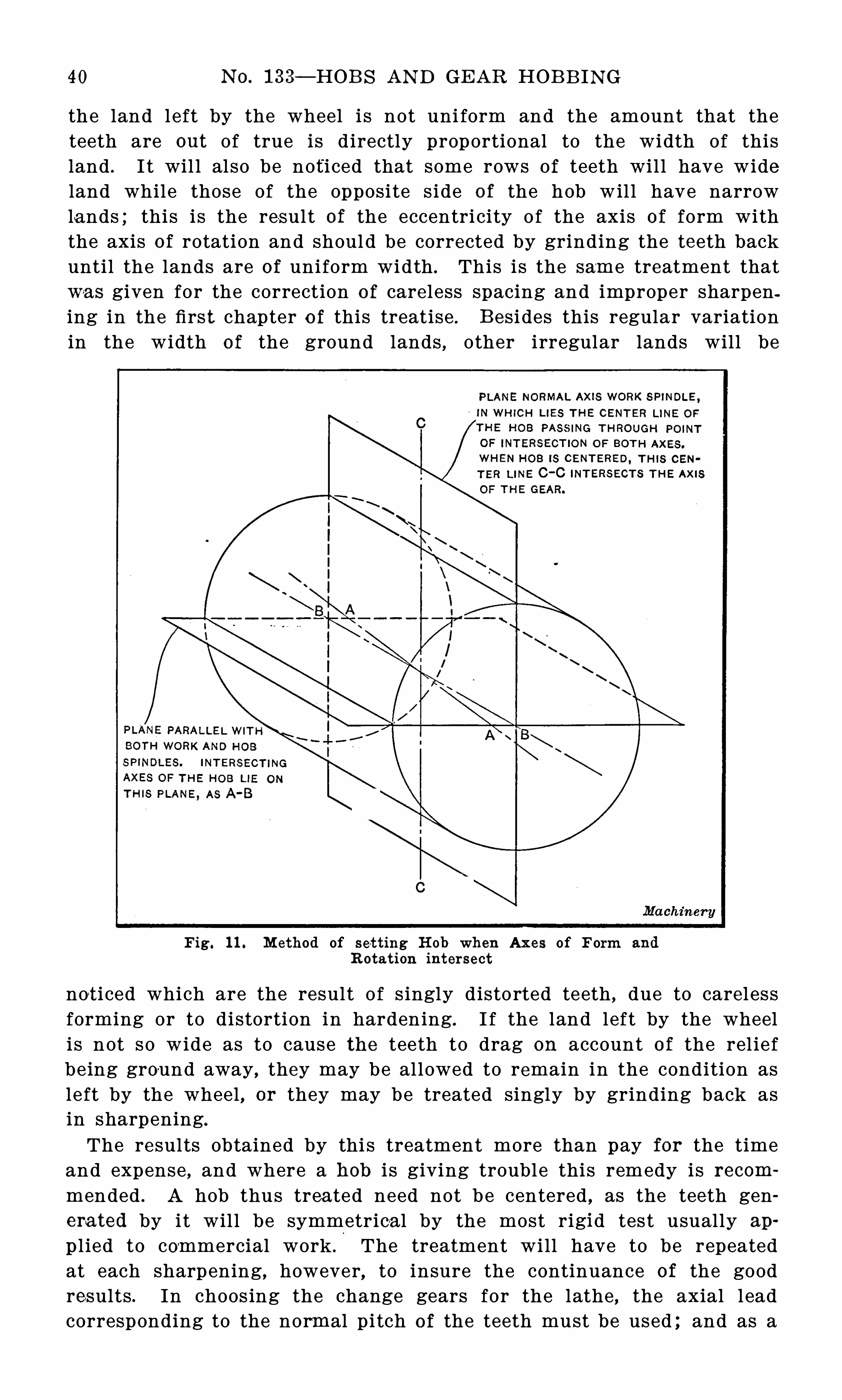
S everal cases could be treated in this way, as for instance , the casewhere the axis of form i s not parallel with the axis of rotation butwhere these axes intersect. The only remedy that would make i t poss ibl e to obtain symmetrical teeth would be to find the point of intersection of the axes and set the hob central wi th that point. B ut
instead o f setting the high tooth central , as in Fig. 5 , the hob shouldbe set in such a positi on that the axis of the form lies in the samep lane as the sp indle on which the gear is placed , and the hob shouldbe set central i rresp ective o f the location of the teeth of the hob .
That is, the hob should be set so that the point o f intersection o f thetwo axes will l i e directly in l ine with the axis of the work sp indleof the machine , whether or not the tooth of the hob comes centra l .O f course i f a
’
tooth comes into this pos ition , so much the better forthe symmetry of the teeth of the gear . This setting is il lustrated inFig. 1 1 . The unsymmetrical resul ts sure to be developed by any othersetting are quite obvious without further exposition .
CE NTE R IN G TH E HOB 39
D e fe ct s in H o bs
The preceding treatment of three typical cases throws some lighton the cause of the poor shape of the teeth so often complained o f
in the results obtained from the hobbing machine, and while this discussion
‘
does not include all of the defects that will produce similarresul ts , i t does emphasize the fact that more care will be necessary inthe preparation of the hob than has formerly been the pract ice .
E ventually we shal l have the ground hob , with the defects o f hardening and careless forming el iminated by grinding the hardened hobson precision machines in which the human element wil l be reducedto a minimum , so far as i ts effect on the accuracy of the hob i sconcerned . When such hobs are availabl e, the hobbing process willmeet with l ittle or no opposition based on the unrel iabl e results oh
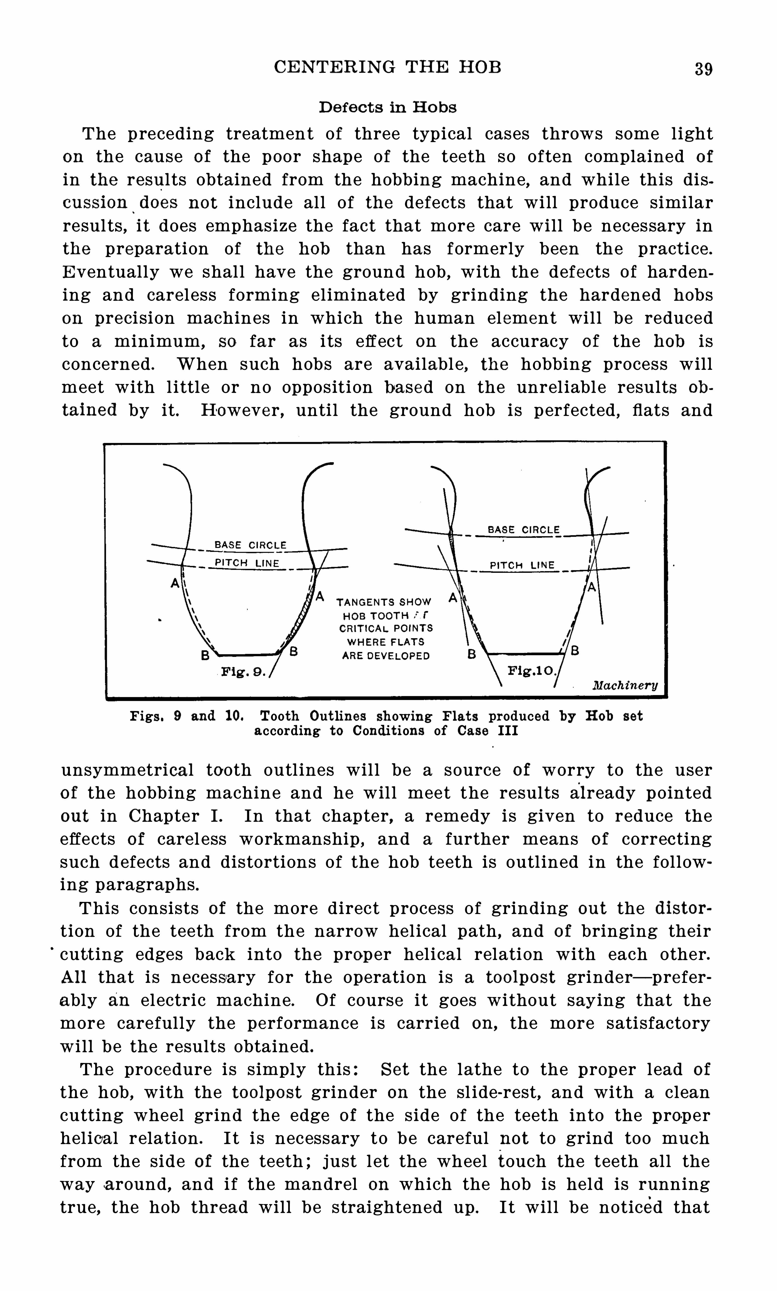
tained by it . However , until the ground hob is perfected , flats and
Figs. 9 and 1 0. Tooth Out lines showing Flats produced by H ob setaccording to Condit ions of Case III
unsymmetrical tooth outl ines wil l be a source of worry to the userof the hobbing machine and he wil l meet the results already pointedout in Chapter I . In that chapter, a remedy is given to reduce theeffects of carel ess workmanship , and a further means of correctingsuch defects and distortions of the hob teeth is outl ined in the fol lowing paragraphs .This consists of the more direct process of grinding out the distor
tion of the teeth from the narrow hel ical path , and of bringing theircutting edges back into the proper helical relation with each other.All that is necessary for the operation is a toolpost grinder— preferably an electric machine . Of course i t goes without saying that themore carefully the performance is carried on , the more sati sfactorywill be the results obtained .
The procedure is simply this:S et the lathe to the proper lead of
the hob,with the toolpost grinder on the sl ide-rest, and with a clean
cutting wheel grind the edge of the side of the teeth into the properhel ical relation . I t i s necessary to be careful not to grind too muchfrom the side of the teeth ; j ust l et the wheel touch the teeth all theway a round , and if the mandrel on which the hob is held is runningtrue
,the hob thread will be straightened up . I t wil l be noticed that
4 0 N O. 1 33— HOB S AN D GE AR HOB B IN G
the land left by the wheel i s not uni form and the amount that theteeth are out of true is d irectly proportional to the width of thisland . I t wil l al so be noti ced that some rows of teeth wil l have wideland while those of the opposite s ide of the hob wil l have narrowlands ; this i s the result of the eccentri city o f the axis of form withthe axis o f rotation and shoul d be corrected by grinding the teeth backuntil the lands are of uniform width . This is the same treatment thatwas given for the correction of carel ess spacing and improper sharpening in the firs t chapter o f this treatise . B esi des this regular variationin the width o f the ground lands , other irregular lands will be
Fig. 1 1 . M ethod of set t ing H ob when Ax es of Form and
R otat ion intersect
not i ced which are the result o f s ingly disto rted teeth , due to carel essforming or to distortion in hardening. I f the land left by the wheeli s not so wide as to cause the teeth to drag on account o f the rel iefbeing ground away , they may be al lowed to remain in the condition asleft by the wheel , or they may be treated singly by grinding back asin sharpening.
The results obtained by thi s treatment more than pay for the timeand expense , and where a hob i s giving trouble this remedy is recom
mended . A hob thus trea ted need not b e centered as the teeth generated by it wil l be symmetrica l by the most rigi d tes t usually ap
p l ied to commercial work . The treatment will have to be repeatedat each sharpening , however, to insure the continuance of the goodresults . In choos ing the change gears for the lathe , the axial l eadcorresponding to the normal pi tch of the teeth must be used ; and as a
HOB B IN G V S . MILLIN G 4 1
difference of inch i s noticeable in the angle of the teeth , thelead must be closely followed . S ome such treatment as this i s neces
sary with the'
irregular hobs now obtainable .
Conc lus ion
The answer to the question:Should the hob be centered % thus,is
that with the unground hob in which the eccentricity is an unknownquantity, but may be taken a s sure to exist, it i s well to center thehigh tooth as in Case I I ; and with the accurate hob , that wil l beavailable when the methods of grinding the teeth are perfected
,i t
wil l be unnecessary to center the hob if the hob has been carefully
sharpened and the hob arbor runs true on i ts axis . Wh i l e the resultsrevealed by the treatment of the three cases seem to be unfavorable tothe hobbing p rocess , i t i s such studies as these that bring the truthto l ight and lead the way to the remedy which , when appl ied , bringsto the hobbing process the share of consideration i t deserves as one
o f the simplest and most efficient methods for the production of the
teeth of gears .
CHAPTER I V
H OB B IN G V S . M ILLIN G OF GEAR S
The adverse criticism of the gearmobbing process has been thecause of many interes ting investigations , and one of the most important of these has been the comparative study of the condition ofthe surfaces produced by the hob and by the rotary cutter . In making such a compa rative study , it is necessary that the investigatorpossess the required practical knowledge , and al so that he be will ingto admit a point, even though his favorite p rocesses may suffer by thecomparison .
F eed Mar%s produce d b y Ro tat ing M i lling Cut te rs
While both the gear hobbing machine and the automatic gear cutteruse rotating cutting tools , the operations cannot be placed on a common basis and cons idered as similar mill ing operations , although theymay , to a certain ex tent, be compared as such . In comparing thequality of the surfaces produced by the two processes , consider firstthe mil led surface produced by an ordinary rotary cutter . This surface has a series o f hil ls and hollows at regular intervals , the spacingbetween these depending upon the feed per revolution of the cutter,and the depth on both the feed and the -diameter of the cutter . Theridges are more prominent wh en coarse feeds and small diametercutters are used . These feed marks are the result of the convex patho f the cutt ing edge and the sl ight running -
out of the cutter, which
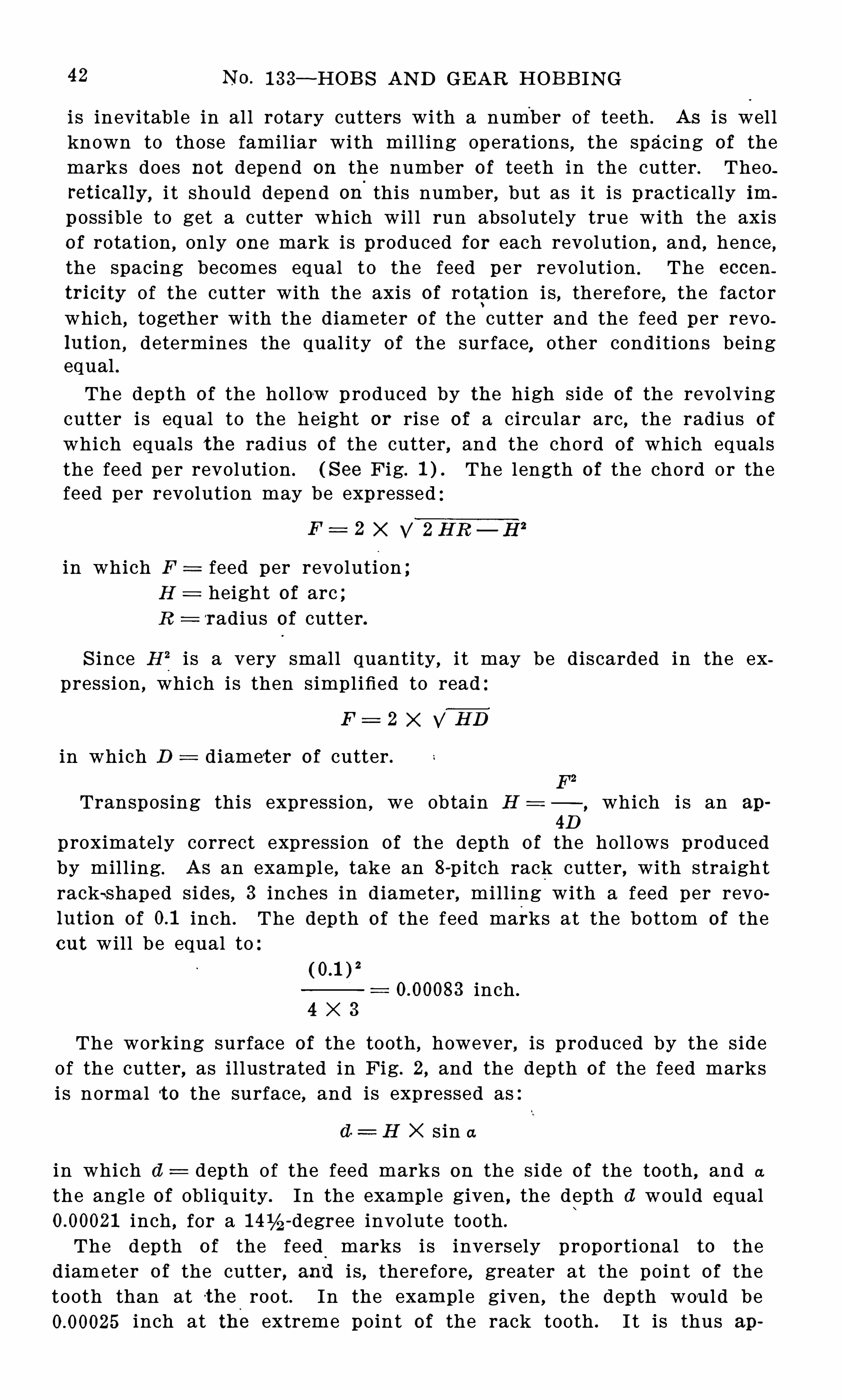
4 2 N o . 1 33 -HOB S AN D GEAR HOB B IN G
is inevitable in al l rotary cutters with a number of teeth . As i s wel lknown to those famil iar with mill ing operations
,the spacing of the
marks does not depend on the number of teeth in the cutter.Theo
retically , i t should depend on
'
this number,but as it is p ractically im
possible to get a cutter which wil l run absolutely true with the axisof rotation , only one mark is produced for each revolution
,and
,hence
,
the spacing becomes equal to the feed per revolution.The eccen
tricity of the cutter with the axis of ro tation i s , therefore, the factorwhich , toget her with the diameter of the cutter and the feed per revolution , determines the qual ity of the surface
,other conditions being
equal .
The depth of the hollow p roduced by the high side of the revolvingcutter i s equal to the height or ris e of a circular arc
,the radius o f
which equals the radius of the cutter, and the chord o f which equalsthe feed per revolution . ( S ee Fig. The length of the chord or thefeed per revolution may be expressed
F = 2 X 2 H R — H 2
in which F = feed per revolution ;H height of arc ;R = radius of cutter.
S ince H % i s a very small quantity, i t may be discarded in the expression , which is then simplified to read
F = 2 X V HD
in which D diamet er of cutter .
Transposing thi s express ion , we obtain H which i s an ap
4 D
proximately correct expression of the depth o f the holl ows producedby mil l ing . As an example , take an 8-p itch rack cutter, with straightrack-s haped sides, 3 inches in d iamete r, mill ing with a feed per revolution of inch . The depth of the feed marks at the bottom of theout will be equal to
inch .
4 X 3
The working surface of the tooth , however, is p roduced by the s ideof the cutter, as il lustrated in Fig. 2, and the depth of the feed marksi s normal t o the surface , and is expressed as
d : H X s in a
in which d depth of the feed marks on the side of the tooth , and a
the angle of obl iquity. In the example given , the depth (1 would equalinch , for a -degree involute tooth .
The depth o f the feed marks i s inversely proportional to thed iameter of the cutter, and i s , therefore, greater at the point of thetooth than at t he root . In the example given , the depth woul d be
inch at the extreme point of the rack tooth . I t is thus ap
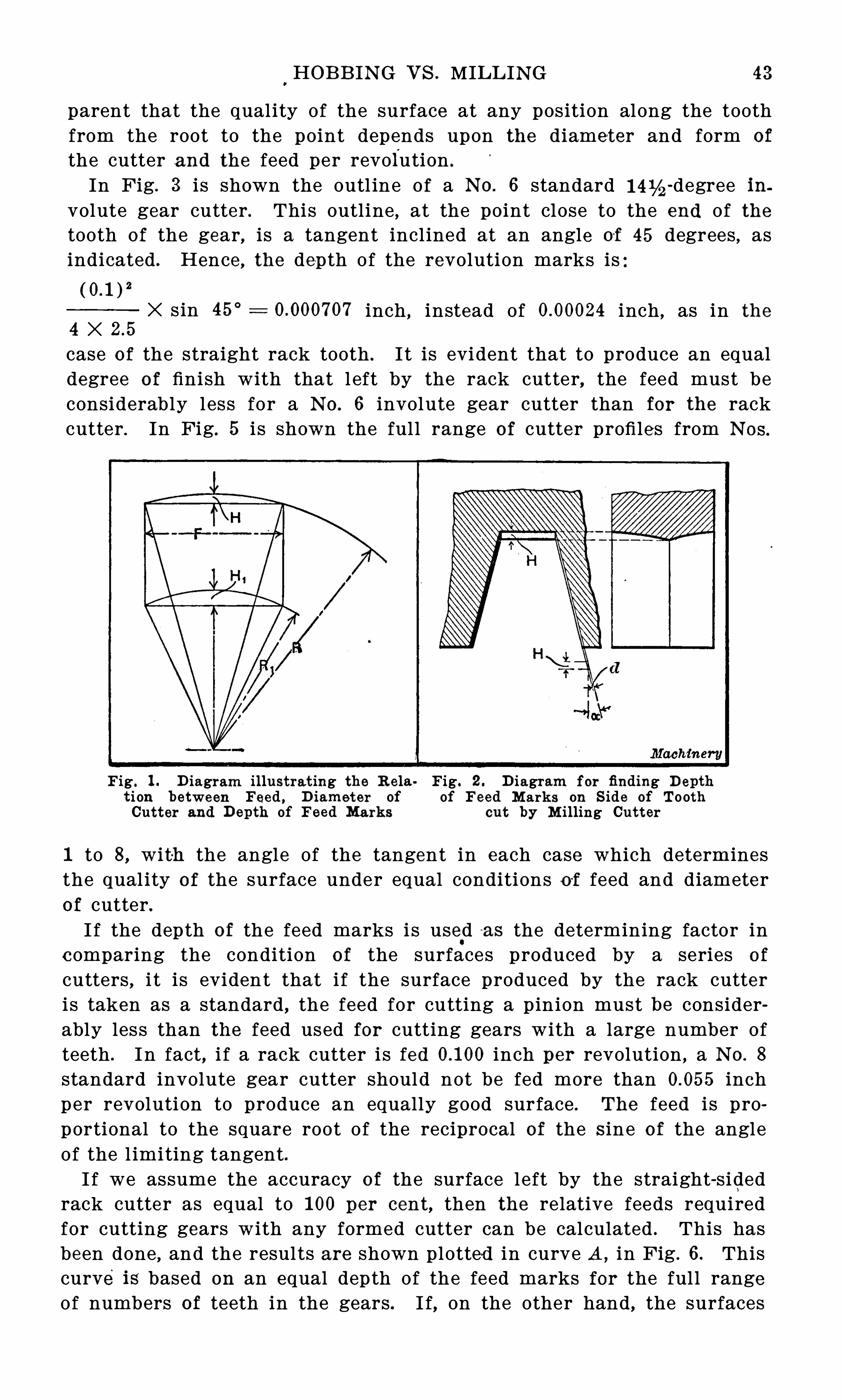
HOB B IN G V S . MILL ING 4 3
parent that the qual ity of the surface at any position along the toothfrom the root to the point depends upon the diameter and form of
the cutter and the feed per revolution .
In Fig. 3 i s shown the outl ine o f a N o . 6 standard -degree involute gear cutter . This outline , at the point close to the end of thetooth of the gear, is a tangent incl ined at an angle of 4 5 degrees
,as
indicated . Hence , the depth of the revolution marks is
X sin 4 5° inch , instead of inch , as in the
4 Xcase of the straight rack tooth . I t is evident that to produce an equaldegree of finish with that l eft by the rack cutter, the feed must beconsiderably l ess for a N o . 6 involute gear cutter than for the rackcutter . In Fig. 5 i s shown the ful l range of cutter profi les from N os.
Fig . 1 . D iagram illustrat ing the R ela Fig. 2 . D iagram for finding D eptht i on between Feed , D iamet er of of Feed M ar%s on S ide of ToothCutter and Depth of Feed Mar%s cut by M illing Cutt er
1 to 8, wit-h the angle of the tangent in each case which determinesthe qual ity o f the surface under equal conditions o f feed and diameterof cutter .I f the depth o f the feed marks i s used a s the determining factor in
comparing the condition of the surfaces produced by a series of
cutters , i t is evident that i f the surface produced by the rack cutteri s taken as a standard , the feed for cutting a pinion must be considerably less than the feed used for cutting gears with a large number ofteeth . I n fact, i f a rack cutter i s fed inch per revolution , a N o . 8
standard involute gear cutter should not be fed more than inchper revolution to produce an equally good surface . The feed is proportional to the square root o f the reciprocal of the s in e of the angleof the l imiting tangent .I f we assume the accuracy of the surface l eft by the straight-sided
rack cutter as equal to 1 00 per cent, then the relative feeds requiredfor cutting gears with any formed cutter can be calculated . This hasbeen done , and the resul ts are shown plotted in curve A , in Fig . 6 . Thiscurve is based on an equal depth of the feed marks for the ful l rangeof numbers of teeth in the gears . I f, on the other hand , the surfaces
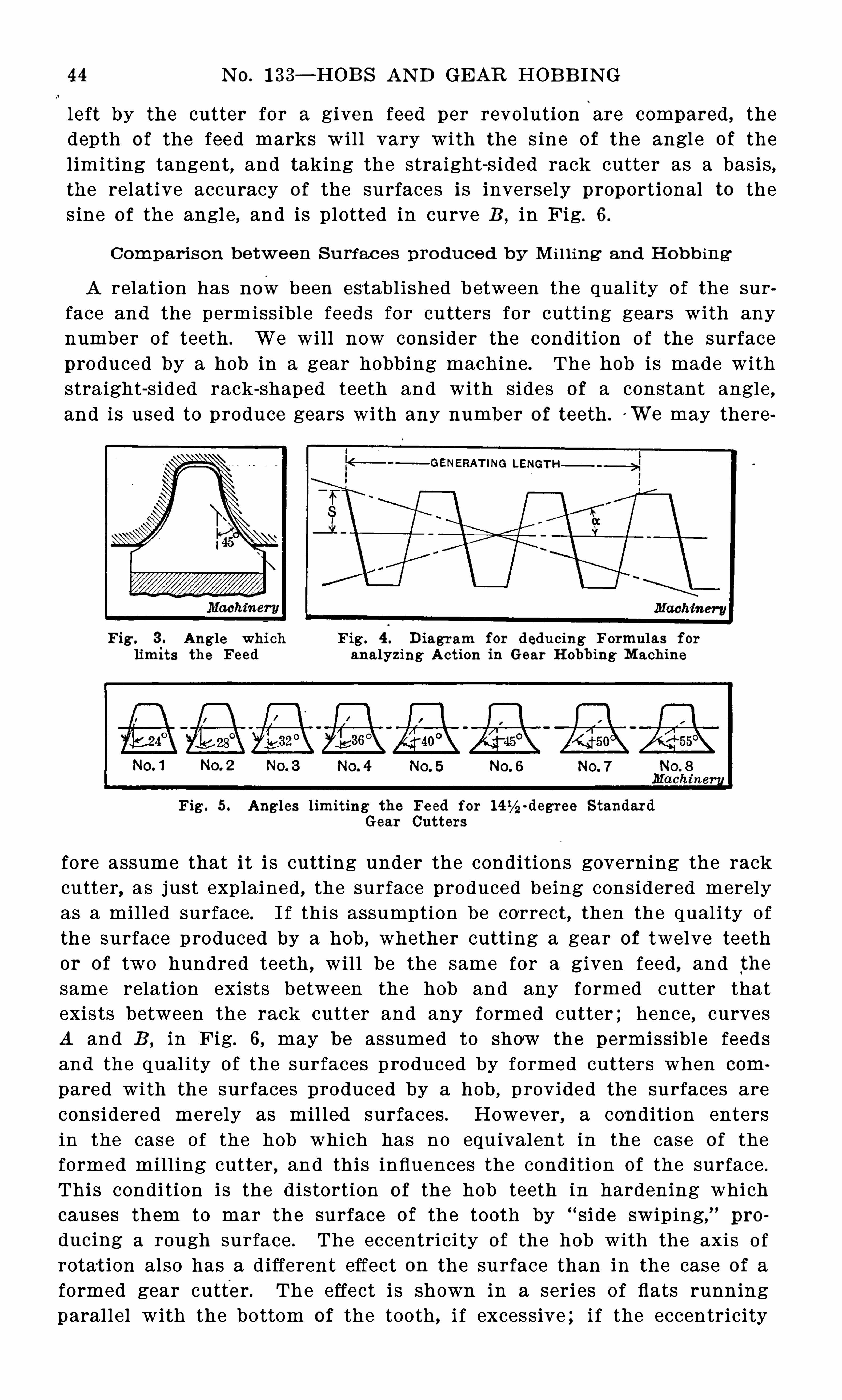
4 4 N O. 1 33— HOB S AN D GEAR HOB B IN G
left by the cutter for a given feed per revolution‘
are compared , thedepth o f the feed marks will vary with the s ine of the angle of thelimiting tangent, and taking the straight-sided rack cutter as a basis,the relative accuracy o f the surfaces i s inversely proportional to thes ine o f the angle , and is plotted in curve B , in Fig. 6 .
Compari son be twe en Surface s pro duced b y M i l l ing an d H ob b ing
A relation has nowbeen establ ished between the qual ity of the surface and the permissibl e feeds for cutters for cutting gears with anynumber of teeth . We will now consider the condition of the surfaceproduced by a hob in a gear hobbing machine . The hob i s made withstraight-sided rack-shaped teeth and with sides of a constant angle,and is used to produce gears with any number o f teeth .
vWe may there
F igs3 . Angle whi ch Fig . 4 . D iagram for deducing Formulas for
limi ts the Feed analyz ing Act ion in Gear H obbing M achine
Fig . 5 . Angles limiting the Fe ed f or 1 4 % -degree S tandardGear Cutters
fore assume that i t i s cutting under the conditions governing the rackcutter, as just explained , the surface produced being considered merelyas a mil led surface. I f thi s assumption be correct, then the qual i ty ofthe surface produced by a hob , whether cutting a gear of twelve teethor of two hundred teeth , wil l be the same for a given feed, and thesame relation exists between the hob and any formed cutter thatexis ts between the rack cutter and any formed cutter ; hence , curvesA and B , in Fig. 6, may be assumed to show the permissibl e feedsand the qual ity of the surfaces p roduced by formed cutters when com
pared with the surfaces produced by a hob , provided the surfaces areconsidered merely as mil led surfaces . However, a con dition entersin the case of the hob which has no equivalent in the case of theformed mill ing cutter , and this influences the condition of the surface .
This condition is the d istortion of the hob teeth in hardening whichcauses them to mar the surface of the tooth by “ side swiping,
%
pro
ducing a rough surface . The eccentrici ty of the hob with the axis o f
rotat ion also has a different effect on the surface than in the case of aformed gear cutter. The effect i s shown in a seri es o f flats runningparallel with the bottom of the tooth, i f excessive ; i f the eccentricity
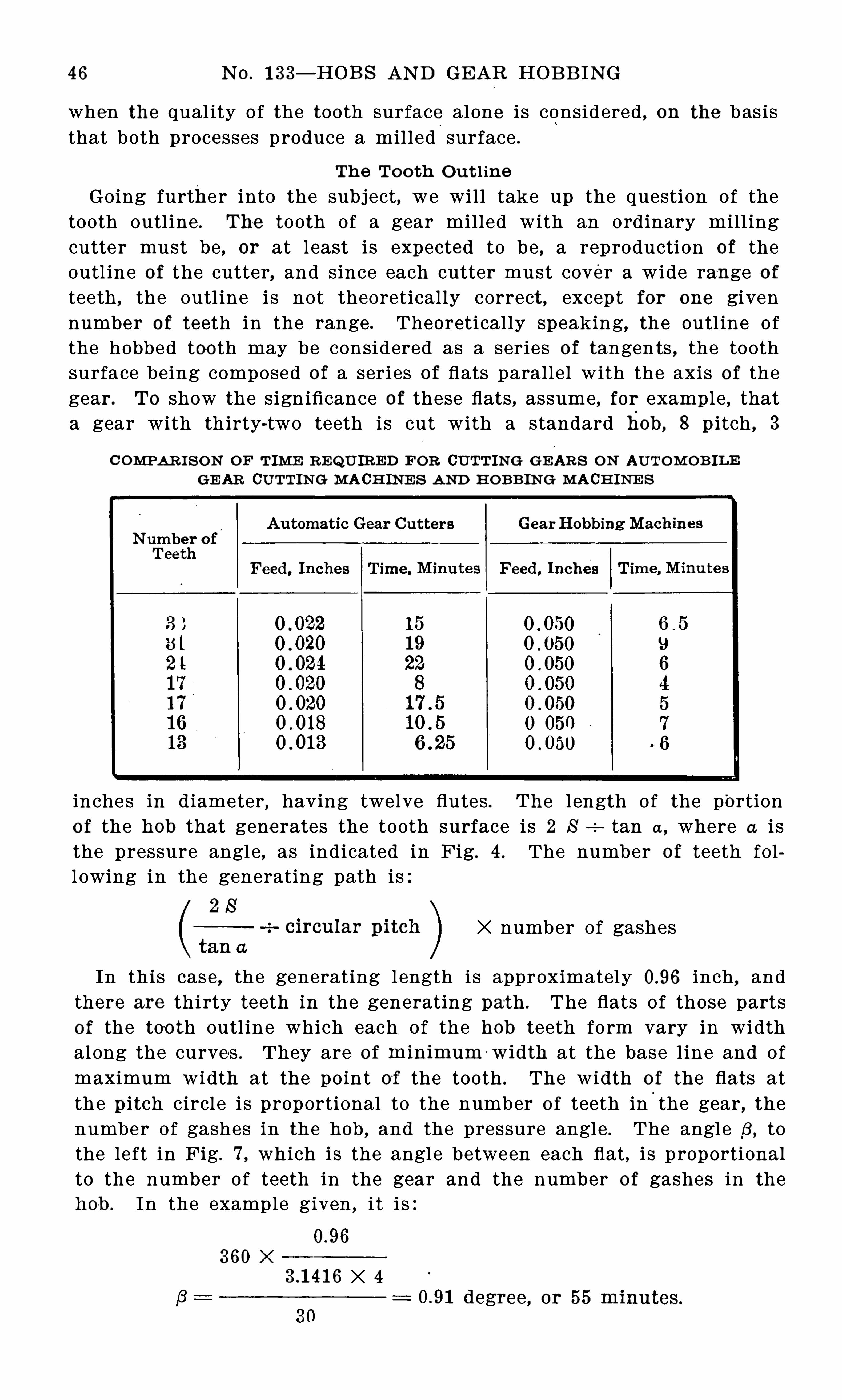
4 6 N O. 1 33— HOB S AN D GEAR HOB B IN G
when the qual ity of the tooth surface alone i s considered , on the basisthat both processes produce a milled surface .
Th e To o th Out l ine
Going further into the subject, we will take up the question of thetooth outl ine . The tooth of a gear milled with an ordinary mill ingcutter must be
, or at l east is expected to be , a reproducti on of theoutl ine of the cutter, and since each cutter must cover a wide ran ge of
teeth,the outl ine is not theoretically correct , except for one given
number of teeth in the range. Theoretically speaking, the outl ine ofthe hobbed too th may be considered as a series of tangents , the toothsurface being composed of a seri es of flats parallel with the axis of thegear . To show the significance of these flats , assume, for example , thata gear with thirty-two teeth is cut with a standard hob , 8 pitch , 3
CONIPAR I S ON OF TIM E R E%U IR ED F OR CUTTIN G GE AR S ON AUTOM OB IL EGE AR CUTTIN G MACH IN E S A N D H OB B IN G M ACH INE S
inches in diameter , having twelve flutes . The l ength of the portion
o f the hob that generates the tooth surface is 2 S tan a , where a i sthe pressure angl e , as indicated in Fig. 4 . The number of teeth foll owing in the generating path is
X number of gashes
In this case, the generating l ength i s approximately inch,and
there are thi rty teeth in the generating path . The flats o f those partso f the too th outl ine which each of the hob teeth form vary in widthal ong the curves . They are o f min imum 'wi dth at the base l ine and ofmaximum width at the point of the tooth . The width o f the flats atthe p itch circl e i s proportional to the number o f teeth in
'
the gear,the
number of gashes in the hob , and the pressure angle . The angle,8 , to
the left in Fig. 7, which is the angle between each flat, i s p roportionalto the number of teeth in the gear and the number of gashes in theho-b . In the example given , i t i s:
360 XX 4
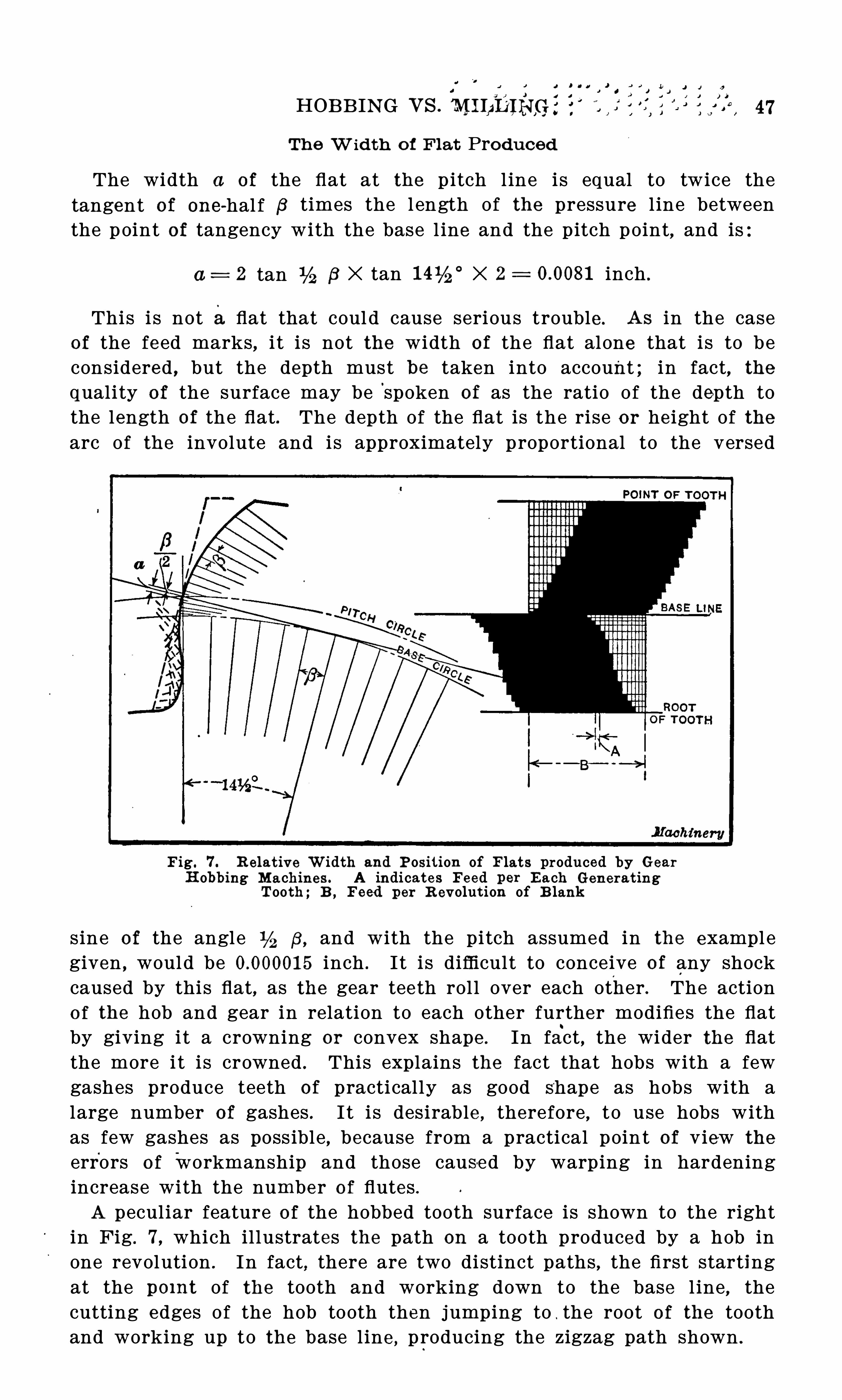
J i u a
HOB B IN G vs. M I LD IHGZ
Th e W id th o f F iat Pro duced
The width a of the flat at the pitch l ine is equal to twice thetangent of one-hal f B times the l ength of the pressure l ine betweenthe p oint o f tangency with the base l ine and the pitch point, and is:
a= 2 tan B X tan X 2 inch .
This i s not a flat that coul d cause serious trouble . As in the caseof the feed marks, i t i s not the width of the flat alone that is to beconsidered , but the depth must be taken into account ; in fact, thequality of the surface may be
'
spoken of as the ratio o f the depth tothe length of the flat . The depth of the flat is the rise o r he ight of thearc of the involute and is approximately proportional to the versed
Fig. 7 . R elat ive W idth and P osit ion of F lats produced by Gear
H obbing M ach ines . A indicates Feed per E ach Gen erat ingTooth ; B ,
Feed per R evolut ion of B lan%
sine of the angle B,and with the pitch assumed in the example
given , would be inch . I t i s difficult to conceive o f any shockcaused by this flat, as the gear teeth rol l over each other . The actiono f the hob and gear in relation to each other further modifies the flatby giving it a crowning or convex shape . In fact , the wider the flatthe more i t i s crowned . This explains the fact that hobs with a fewgashes produce teeth of practically as good shape as hobs with alarge number o f gashes . I t i s desirable , therefore , to use hobs withas few gashes as poss ible , because from a practical poin t of view the
errors o f workmanship and those caused by warping in hardeningincrease with the number o f flutes .
A pecul iar feature o f the hobbed tooth surface i s shown to the rightin Fig. 7, which il lustrates the path on a tooth produced by a hob inone revolution . In fact, there are two distinct paths , the first startingat the pomt of the tooth and working down to the base l ine , thecutting edges of the hob tooth then jumping to . the root of the toothand working up to the base l ine , producing the zigzag path shown .
‘v ‘ n z r i x n
Na. 1*
as~Hoes A'N D GEAR HOB B IN G
Conc lusion
That the flats so commonly seen in the resul ts obtained from % thehobbing machine are not due to any faul ts o f the process that cannotbe corrected , but are due to either carelessness on the part of theoperator in setting up the machine without proper support to thework or to the poor condition o f the hob or machine , and that nearlyall cases o f flats can be overcome by the use of a proper hob , may beassumed as a statement o f facts . When the hobbing machine will notgive good results , the hob is in nearly all cases at faul t. I f a gear isproduced that bears hard on the point of the teeth , has a flat at thep itch l ine or at any point along the face o f the tooth do not thinkthat the process i s faulty in theory , or that the machine 1 s not properlyadjusted , or that the strain of the cut is causing undue torsion in theshafts, or that there i s backlash between the gears in the train connecting the work and the hob ; these things are not as l ikely to causethe trouble as is a faulty hob .
After an experience covering all makes of hobbing machines , thewriter has come to the conclusion that the real cause of the troubl ein nearly every case is
'
a faulty hob . Machine after machine has beentaken apart, overhauled and readjusted , and y et no be tter resul ts havebeen obtained until a new and bet ter hob was produced .
( The faultsusually met with in hobs were referred to in Chapter I , and themeans for getting the hob into a good working condition were al soexplained there. I t i s not desired in any way to d isparage
'
t he formedcutter process in favor of the hobbing process , but simply to state thefacts as they appear . I n
‘
every case , practice seems to substantiate theconclus ions arrived at.


THI S B OO% I S DUE ON THE LAST DATE
STAMPED B ELOW
AN.
IN ITIAL F IN E or 25 CE NTSW ILL B E AS S ES S ED FOR FAILUR E TO RETURN
TH IS B OO % ON TH E DATE DUE . TH E P EN ALTYW ILL IN C R EAS E TO 5 0 C ENTS ON TH E FOURTH
DAY AN D TO ON TH E S EV ENTH DAY