Embed Size (px)
Citation preview
HO Structure Kit 90’ NON-MOTORIZED
TURNTABLE 933-3171
© 2011 Wm. K. Walthers, Inc., Milwaukee, WI 53218 waltherscornerstone.com I-3171

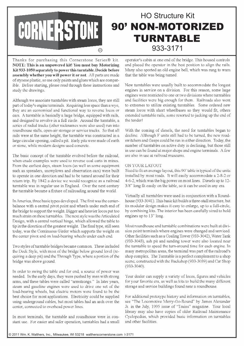
1. Place the upper bearing (21) into the pit (!). Use a small amount of CA type cement to hold it in place.2. Place the lower bearing (22) into the recess of the mechanism cover (29) [See illustration on next page].3. Assemble the bogie halves (17 and 18) together, with the wheels (20) sandwiched in between and turning freely in the cone-shaped
bearing surfaces. Glue on the end pieces (19). Glue the bogie assemblies into the pockets at the ends of the bridge (2).4. Place the bridge (2) upside down on your work surface and set the pit (1) upside down on top of it, with the bridge shaft going through
the hole in the pit.
5. Glue the (simulated) motor housing sides (15 and 16) to the underside of the bridge deck (3). Then position, but do not glue, the deck onto the bridge (2), noting that the long ties for the control cab are on the side of the bridge that has 2 holes. Remove the deck and feed the track power wires between the ties of the deck, closest to the center of the deck lengthwise, and between the inner guard timbers and the walkway boards. Glue the bridge to the deck, and then pull the wires all the way out through the deck.
6. Cut 2 pieces of rail (not included) slightly longer than the bridge. Place the rails on the bridge, overhanging equally at each end, but do not glue yet. Mark each rail where it is closest to a wire.
7. Remove the rails from the bridge. Sol¬der a wire to the bottom of the rail by the spot you marked. Hint: scrape the area to be soldered with an X-Acto blade or sandpa-per to obtain a clean surface essential for solder¬ing.
8. Test fit the rails onto the bridge deck to be sure the soldered joints do not interfere with wheel flanges. File if necessary. If OK, glue the rails to the bridge deck, using CA cement, feeding the wires back down through the ties. Use a track laying jig or NMRA standards gauge to make sure the rails are properly spaced. After the glue dries, trim the rails to the length of the bridge with a flush cutter or cutoff disc in a motor tool. Filing a slight bevel on the ends of the rail heads will help guide a loco’s wheel flanges when coming onto the turntable.
9. Assemble the cab (6, 7, 8, 9) together and to the deck as shown in the illustration. The cab doorway faces the end of the deck.
10. Assemble the power arch (10 and 11). Slip the power collector (12) onto the pin in the center, but do not glue. Place the retainer (13) on top and glue it carefully so that the power collector is tree to rotate. For added detail, dummy wires can be glued to the “insula¬tors” and run to a power pole near the edge of the pit.
11. Glue the handrails (4 and 5) to the deck, with the lengthwise railings facing inside. The bottoms of the posts should be even with the bottoms of the long ties. The posts glue to the sides of the long ties where they protrude from under the walkway boards.
12. Glue the (simulated) turntable drive support (14) into the holes in the bridge side and onto the motor housing sides (15 and 16). The notches in 15 and 16 should fit over the braces of part 14.
13
12 11
10 10
9
8 6
8
7
20
18
19
19
17
5 15
16
14
4
3
20
17
19
19
18
1
21

13. Place the metal washer (50) onto the shaft with the surface that has the rounded edges against the pit. Remove the big gear (33) from the sprue and place it onto the shaft as far as it will go on top of the washer. The “nubs” from the sprue should be down that is, next to the pit bottom. Use CA type cement to secure the big gear to the shaft.
14. Cut 2 pieces of wire about 5” long. Strip about ¼” of insulation from each end. Solder the free end of one of the wires to the inter surface of the brass tube (35). Repeat with other wire and tube. Slip one of the tubes onto the bridge shaft, feeding the wire into the slot and through the shaft. Glue the plastic spacer ring (28) onto the shaft. Repeat with the second brass tube. A small amount of Goo on the shaft before placing the second brass tube will help keep it in place.
15. To install Motorizing Kit, 933-1050, (Sold separately) continue reading. Skip to step 16 if not using the Motorizing Kit. Use two of the provided self-tapping screws, mount the motor/gearbox (30) to the bottom of the mechanism cover (29).
16. Using the machine screws (37), attach the electrical wipers (36) to piece 26. Do not tighten the nuts (38) yet. Temporarily place the piece 26 into position to see how much the wipers must be bent to make good contact with the brass tubes (35).
17. Cut the remaining wire into 2 pices and strip the insulation from each end. Bend one end of each wire into a cook. Loosen the nuts (38) and slip a wire under each, and then tighten. Be careful that the wipers do not touch each other. Wrapping some tape around one of the wipers will maintain the necessary gap.
18. Use a maker or some other means to distinguish the motor wires from the track power wires. Fasten the mechanism cover (29) onto the pit bottom with the 4 self tapping screws. Make sure that the tab on piece 26 is guided into the slot in part 29. The wire should emerge from the gap near motor gearbox.
19. When you have determined the location of the turntable, mark a circle 12 5/8” in diameter. All tracks coming from the turntable should be in line with the center of the circle, so it is best to mark their centerlines before cutting the hole. Cut the hole with a saber saw and test fit the pit. Use a wood rasp or file to finish the opening if it is too tight.
20. Connect the wires to appropriate power source. The track power feeders should be routed through a reversing switch independently from the approach track(s). The motor drive power should be controlled through a center-off type revers-ing switch. Since the mtor operated more realistically at less than its full 12 volts DC, an inexpensive power pack can supply power, speed and directional control for the motor.
DECALING1. After cutting out the decal, dip in water for 10 seconds, remove
and let stand for I minute. Slide decal onto surface, position and then blot off any excess water.
2. Lightly brush Micro Sol® on top. This will soften the decal allow-ing it to conform to irregular surfaces. DO NOT TOUCH DECAL while wet!
3. When the decal is thoroughly dry, check for any trapped air bubbles. Prick them with the point of a small pin or hobby knife blade and apply more Micro Sol®.
1
50 33
35 28
36 38
37 26
Self-Tapping Screw
Make sure the rounded edges go up towards the bottom of the pits.
933-1050 Motor/Gearbox (Available Separately)
29
22
Self-Tapping Screw x4