Embed Size (px)
Citation preview

Edition February 2011
© S
iem
ens
Nix
dorf
Info
rmat
ion
ssys
tem
e A
G 1
995
Pfa
d: N
:\allg
eme
in\S
KP
-HN
C\B
üche
r\N
eu\H
NC
\en\
hnc.
vor
User Guide - English
HNC Software 2.0High-Speed Network Connect
HNC-V 91854 HNC-IV 91853

Comments… Suggestions… Corrections…The User Documentation Department would like to know your opinion on this manual. Your feedback helps us to optimize our documentation to suit your individual needs.
Feel free to send us your comments by e-mail to: [email protected]
Certified documentation according to DIN EN ISO 9001:2008To ensure a consistently high quality standard anduser-friendliness, this documentation was created tomeet the regulations of a quality management system which complies with the requirements of the standardDIN EN ISO 9001:2008.
cognitas. Gesellschaft für Technik-Dokumentation mbHwww.cognitas.de
Copyright and Trademarks
This manual is printed on paper treated with chlorine-free bleach.
Copyright © Fujitsu Technology Solutions GmbH 2011.
All rights reserved.Delivery subject to availability; right of technical modifications reserved.
All hardware and software names used are trademarks of their respective manufacturers.
Linux is a registered trademark of Linus Torvalds.
The Linux-based HNC system include open source software. You will find the licenses for this software in the LICENSES directory on the installation DVD.
Intel und Xeon are trademarks of Intel Corporation in the USA and other countries.

U41655-J-Z125-4-74
Dok
usch
ablo
nen
19x
24 V
ers
ion
7.3
2de
für
Fra
me
Mak
er V
7.x
vom
28.
03.2
007
© c
ogn
itas
Gm
bH
20
01-2
007
7. M
ärz
201
1 S
tand
14
:44.
27P
fad
: N:\a
llgem
ein
\SK
P-H
NC
\Büc
her\
Ne
u\H
NC
\en\
hnc.
ivz
Contents
1 Preface . . . . . . . . . . . . . . . . . . . . . . . . . . . . . . . . . . . . . . . . . . 7
1.1 Target group . . . . . . . . . . . . . . . . . . . . . . . . . . . . . . . . . . . . . . . 7
1.2 Summary of the contents . . . . . . . . . . . . . . . . . . . . . . . . . . . . . . . . 7
1.3 Changes since the last version of the manual . . . . . . . . . . . . . . . . . . . . 8
1.4 Open Source Software . . . . . . . . . . . . . . . . . . . . . . . . . . . . . . . . . 8
1.5 Notational conventions . . . . . . . . . . . . . . . . . . . . . . . . . . . . . . . . . 9
2 Architecture . . . . . . . . . . . . . . . . . . . . . . . . . . . . . . . . . . . . . . 11
2.1 Basic mode of operation . . . . . . . . . . . . . . . . . . . . . . . . . . . . . . . 132.1.1 LAN connection of the HNC . . . . . . . . . . . . . . . . . . . . . . . . . . . . . . 152.1.2 BS2000 connections and emulated BS2000 devices . . . . . . . . . . . . . . . . . 15
2.2 Hardware . . . . . . . . . . . . . . . . . . . . . . . . . . . . . . . . . . . . . . . 16
2.3 Software . . . . . . . . . . . . . . . . . . . . . . . . . . . . . . . . . . . . . . . . 18
3 Operating the HNC . . . . . . . . . . . . . . . . . . . . . . . . . . . . . . . . . . 19
3.1 HNC Manager . . . . . . . . . . . . . . . . . . . . . . . . . . . . . . . . . . . . . 193.1.1 Calling the HNC Manager . . . . . . . . . . . . . . . . . . . . . . . . . . . . . . . 203.1.2 Logging in . . . . . . . . . . . . . . . . . . . . . . . . . . . . . . . . . . . . . . . 203.1.3 Logging out . . . . . . . . . . . . . . . . . . . . . . . . . . . . . . . . . . . . . . . 213.1.4 Session management . . . . . . . . . . . . . . . . . . . . . . . . . . . . . . . . . 223.1.5 Interface of the HNC Manager . . . . . . . . . . . . . . . . . . . . . . . . . . . . . 223.1.5.1 Window types . . . . . . . . . . . . . . . . . . . . . . . . . . . . . . . . . . . 223.1.5.2 Main window . . . . . . . . . . . . . . . . . . . . . . . . . . . . . . . . . . . . 233.1.5.3 Dialog boxes . . . . . . . . . . . . . . . . . . . . . . . . . . . . . . . . . . . . 253.1.6 Calling an object or function . . . . . . . . . . . . . . . . . . . . . . . . . . . . . . 263.1.7 Navigation . . . . . . . . . . . . . . . . . . . . . . . . . . . . . . . . . . . . . . . 27

Inhalt
U41655-J-Z125-4-74
3.1.8 Filtering a table . . . . . . . . . . . . . . . . . . . . . . . . . . . . . . . . . . . . . 273.1.9 Sorting a table . . . . . . . . . . . . . . . . . . . . . . . . . . . . . . . . . . . . . . 273.1.10 Calling the online help . . . . . . . . . . . . . . . . . . . . . . . . . . . . . . . . . 283.1.11 Error handling . . . . . . . . . . . . . . . . . . . . . . . . . . . . . . . . . . . . . . 30
3.2 Access to the CLI . . . . . . . . . . . . . . . . . . . . . . . . . . . . . . . . . . . 313.2.1 Opening a terminal window . . . . . . . . . . . . . . . . . . . . . . . . . . . . . . . 313.2.2 Closing the terminal window . . . . . . . . . . . . . . . . . . . . . . . . . . . . . . 313.2.3 Commands . . . . . . . . . . . . . . . . . . . . . . . . . . . . . . . . . . . . . . . 323.2.3.1 auditLog . . . . . . . . . . . . . . . . . . . . . . . . . . . . . . . . . . . . . . . 323.2.3.2 cli_info . . . . . . . . . . . . . . . . . . . . . . . . . . . . . . . . . . . . . . . . 323.2.3.3 init . . . . . . . . . . . . . . . . . . . . . . . . . . . . . . . . . . . . . . . . . . 32
4 BS2000 connections . . . . . . . . . . . . . . . . . . . . . . . . . . . . . . . . . . 33
5 Managing the HNC . . . . . . . . . . . . . . . . . . . . . . . . . . . . . . . . . . . 39
5.1 Querying information about the HNC . . . . . . . . . . . . . . . . . . . . . . . . 39
5.2 HNC configuration . . . . . . . . . . . . . . . . . . . . . . . . . . . . . . . . . . . 415.2.1 Managing the host name, default gateway, LAN interfaces, and DNS configuration . . 415.2.2 Configuring the system time . . . . . . . . . . . . . . . . . . . . . . . . . . . . . . 425.2.3 Configuring SNMP . . . . . . . . . . . . . . . . . . . . . . . . . . . . . . . . . . . 435.2.4 Managing links to external devices . . . . . . . . . . . . . . . . . . . . . . . . . . . 45
5.3 Managing accounts . . . . . . . . . . . . . . . . . . . . . . . . . . . . . . . . . . 465.3.1 Managing local accounts . . . . . . . . . . . . . . . . . . . . . . . . . . . . . . . . 465.3.2 Passwords . . . . . . . . . . . . . . . . . . . . . . . . . . . . . . . . . . . . . . . . 475.3.3 Configuring access to an LDAP server . . . . . . . . . . . . . . . . . . . . . . . . . 485.3.4 Managing LDAP accounts . . . . . . . . . . . . . . . . . . . . . . . . . . . . . . . 49
5.4 Managing backups (CSR) . . . . . . . . . . . . . . . . . . . . . . . . . . . . . . . 50
5.5 Powering the HNC on and off . . . . . . . . . . . . . . . . . . . . . . . . . . . . . 52

Inhalt
U41655-J-Z125-4-74
© S
iem
ens
Nix
dor
f Inf
orm
atio
nssy
stem
e A
G 1
995
P
fad:
N:\
allg
em
ein\
SK
P-H
NC
\Bü
cher
\Neu
\HN
C\e
n\h
nc.iv
z
6 Diagnostics and maintenance . . . . . . . . . . . . . . . . . . . . . . . . . . . . 53
6.1 Maintenance concept . . . . . . . . . . . . . . . . . . . . . . . . . . . . . . . . . 536.1.1 Remote service . . . . . . . . . . . . . . . . . . . . . . . . . . . . . . . . . . . . . 536.1.2 Tasks of Customer Support . . . . . . . . . . . . . . . . . . . . . . . . . . . . . . 546.1.3 Tasks of the customer . . . . . . . . . . . . . . . . . . . . . . . . . . . . . . . . . 55
6.2 Updates . . . . . . . . . . . . . . . . . . . . . . . . . . . . . . . . . . . . . . . . 566.2.1 Tasks and responsibilities . . . . . . . . . . . . . . . . . . . . . . . . . . . . . . . 576.2.2 Obtaining updates . . . . . . . . . . . . . . . . . . . . . . . . . . . . . . . . . . . 576.2.3 Managing updates . . . . . . . . . . . . . . . . . . . . . . . . . . . . . . . . . . . 586.2.4 Actions for updates . . . . . . . . . . . . . . . . . . . . . . . . . . . . . . . . . . . 58
6.3 Assisting Customer Support . . . . . . . . . . . . . . . . . . . . . . . . . . . . . 59
6.4 Diagnostic data . . . . . . . . . . . . . . . . . . . . . . . . . . . . . . . . . . . . 60
6.5 System log (audit log) . . . . . . . . . . . . . . . . . . . . . . . . . . . . . . . . 61
Related publications . . . . . . . . . . . . . . . . . . . . . . . . . . . . . . . . . 63
Index . . . . . . . . . . . . . . . . . . . . . . . . . . . . . . . . . . . . . . . . . . 65

Inhalt
U41655-J-Z125-4-74

U41655-J-Z125-4-74 7
Dok
usch
ablo
nen
19x
24 V
ers
ion
7.4
us fü
r Fr
ameM
aker
V7
.xvo
m 0
9.02
.201
0©
co
gnita
s G
mb
H 2
001
-20
107
. Mä
rz 2
011
Sta
nd
14:4
4.27
Pfa
d: N
:\allg
em
ein
\SK
P-H
NC
\Büc
her\
Ne
u\H
NC
\en\
hnc.
k01
1 Preface This manual describes the architecture and concept of the High-speed Network Connect (abbreviated to: HNC). The HNC connects S servers to the LAN. The HNC offers a Web interface, the HNC Manager, for its operation and management.
1.1 Target group
This manual is intended for systems support and the network administrator.
It is assumed readers have a knowledge of BS2000 system operation, BS2000 systems support, and BS2000 administration.
1.2 Summary of the contents
The documentation for the HNC with the software status 2.0 (HNC-V 91854 and HNC-IV 91853) consists of this manual, the Security Manual, and the online help.
● The manual provides an overview of the architecture and concepts of the HNC and presents its functions.
● The Security Manual [6], which also applies for the SQ server and the SKP, describes aspects which are relevant to security for the HNC.
● The online help describes all the functions of the HNC Manager. You open the online help in the HNC Manager, see also Calling the online help.
The manual is structured as follows:
The chapter “Architecture” provides a schematic description of the HNC’s architecture and hardware and the connections to the S server.
The chapter “Operating the HNC” explains the structure of the Web interface and how the HNC is accessed via the CLI (Command Line Interface).
The chapter “BS2000 connections” describes the main function of the HNC, which is to monitor BS2000 connections and, when required, to restart them.

Changes since the last version of the manual Preface
8 U41655-J-Z125-4-74
The chapter “Managing the HNC” describes how you manage the HNC using the functions of the HNC Management in the HNC Manager.
The chapter “Diagnostics and maintenance” describes how you perform maintenance for the HNC and how you proceed when a fault occurs.
These chapters are followed by the chapter on related publications and an index.
Further documentation
The manuals “System Installation” [1] and “Introductory Guide to Systems Support” [2] are recommended for obtaining a basic understanding of BS2000/OSD.
The ”VM2000” manual [3] is recommended for obtaining a basic understanding of VM2000.
The “openNet Server BCAM” manual [4] is recommended to provide further information on the data communication system BCAM.
The BS2000/OSD commands referred to in this manual are described in the “Commands” manual [5], and the VM2000 commands in the “VM2000” manual [3].
Operation of the S servers is described in the relevant “Business Server Sxxx” Operating Manuals.
Operation of the PRIMERGY server of the TX300 series which is used as the hardware basis for the HNC is described in the relevant Operating Manual.
1.3 Changes since the last version of the manual
This manual has been completely revised to describe the new functions of the HNC.
1.4 Open Source Software
The Linux-based base system of the HNC contains Open Source Software. The licenses for this are contained in the LICENSES directory on the relevant installation DVD.

Preface Notational conventions
U41655-J-Z125-4-74 9
Dok
usch
ablo
nen
19x
24 V
ers
ion
7.4
us fü
r Fr
ameM
aker
V7
.xvo
m 0
9.02
.201
0©
co
gnita
s G
mb
H 2
001
-20
107
. Mä
rz 2
011
Sta
nd
14:4
4.27
Pfa
d: N
:\allg
em
ein
\SK
P-H
NC
\Büc
her\
Ne
u\H
NC
\en\
hnc.
k01
1.5 Notational conventions
The following notational conventions are used in this manual:
The following abbreviations are used in this manual:
● S server for the business servers of the S series (/390 architecture)
● BS2000 for the BS2000/OSD operating system in compound nouns,e.g. BS2000 system.
In the text, references to other manuals are made in abbreviated form. The full title of each publication is referenced by a number in square brackets and can be found in the “Related publications” under this number.
I Indicates important information and tips.
V Indicates a warning of data loss.
Ê Indicates the action which you must perform.
italics Indicates texts from the Web interface.
monospaced Indicates system inputs and outputs.
monospaced semibold
Indicates statements which are entered via the keyboard.
UPPERCASE LETTERS
Indicates BS2000 commands.
<abc> Indicates variables which are replaced by values.
[Key symbols] Keys are displayed as they appear on the keyboard. When uppercase letters need to be entered, the Shift key is specified, e.g. [SHIFT] - [A] for A. If two keys need to be pressed at the same time, this is indicated by a hyphen between the key symbols.
Table 1: Notational conventions

Notational conventions Preface
10 U41655-J-Z125-4-74

U41655-J-Z125-4-74 11
Dok
usch
ablo
nen
19x
24 V
ers
ion
7.4
us fü
r Fr
ameM
aker
V7
.xvo
m 0
9.02
.201
0©
co
gnita
s G
mb
H 2
001
-20
107
. Mä
rz 2
011
Sta
nd
14:4
4.27
Pfa
d: N
:\allg
em
ein
\SK
P-H
NC
\Büc
her\
Ne
u\H
NC
\en\
hnc.
k02
2 ArchitectureThe HNC (High-speed Network Connect) connects the BS2000/OSD system (or the BS2000/OSD systems) of an S server to the LAN (connection type ZASLAN). The S server can be connected to the HNC via Fibre Channel (FC) or ESCON (only on the hardware of the HNC-IV 91853).
The FC connection on the S server is established either via an FC switch or directly on the S server’s FC channel.
The two integrated channel connections (ports on the FC and/or ESCON controllers) enable the HNC to be connected to the same or to two different S servers. Details of a redundancy strategy which this approach are provided in the BCAM manual [4].
The HNC can also be connected in parallel to another HNC or to disk systems on the same FC channel of the S server.
The HNC also supports communication between different BS2000/OSD systems (connection type LOCLAN) which
● are running on the same BS2000 server
● are running on two different BS2000 servers which are connected to the same HNC
Data transfer is handled internally in the HNC without any load being placed on the network.
BS2000 connections, i.e. communication connections between the BS2000/OSD systems and the LAN, are established by means of virtual network connections (also referred to as VCAs = Virtual Channel Adapters in other documents).
The HNC supports the operation of a large number of VMs or BS2000/OSD systems with:
● up to 128 BS2000 connections per Fibre Channel
● up to 128 BS2000 connections in the case of ESCON (HNC-IV 91853)
The ZASLAN connections which can actually be configured on an HNC depend on the number of licenses/MAC addresses which are available.
For security reasons, the basic version of the HNC already offers its own physically separated LAN connections for administration (administration LAN), for maintenance and remote service (service LAN), and for the network connection of the BS2000 systems (BS2000 connections of the type ZASLAN). This ensures that the administration paths are decoupled from the data transfer paths.

Architecture
12 U41655-J-Z125-4-74
The HNC Manager is the graphical Web interface of the HNC and offers the following functions:
● Detailed display of all BS2000 connection, including the current status and the option of restarting individual BS2000 connections. The service engineer configures the BS2000 connections or VCAs (one emulated device pair per BS2000 connection) when the HNC is placed in service.
● Display of the information required for the HNC software and hardware, including the current status
● Management of the authorizations for accessing the HNC
● Administration of the HNC, e.g. LAN configuration or NTP
● Maintenance of the HNC, e.g. configuration data backup or update

Architecture Basic mode of operation
U41655-J-Z125-4-74 13
Dok
usch
ablo
nen
19x
24 V
ers
ion
7.4
us fü
r Fr
ameM
aker
V7
.xvo
m 0
9.02
.201
0©
co
gnita
s G
mb
H 2
001
-20
107
. Mä
rz 2
011
Sta
nd
14:4
4.27
Pfa
d: N
:\allg
em
ein
\SK
P-H
NC
\Büc
her\
Ne
u\H
NC
\en\
hnc.
k02
2.1 Basic mode of operation
The figure below provides a schematic view of the possible connections of the HNC-IV and HNC-V. It displays only the components and connections which are relevant for this manual.
* HNC-IV only
Data transfer between the BS2000 system and the connected LANs is implemented via a device pair (WRITE and READ devices).
Data packets are generated by a BS2000 system and sent via a channel (WRITE device) and the internal HNC LAN component SLAN (shared LAN) to one of the connected LANs, or they are received by the SLAN and forwarded via the device address of a channel (READ device) to a BS2000 system (connection type ZASLAN).
The BS2000/OSD system can be connected to the HNC via Fibre Channel (FC) or via an ESCON channel (HNC-IV 91853 only). The FC controller is identified unambiguously by its WWPN (World Wide Port Name).
Administration LAN
Channel conn.
FC connection
BS2000(BS2-MAC_ADR 2)
....
S server
LOCLANSLAN
ZASLAN
HNC
PC
BS2000(BS2-MAC_ADR 1)
VM 1
VM 2
LAN controller(MAC_ADR 1+2+ ...)
Production LAN (ZASLAN)
Onboard LAN
ESCONcontroller*
FC controller(WWPN) VM n
Customer supportnotebook (optional)
Service LAN
adminservice

Basic mode of operation Architecture
14 U41655-J-Z125-4-74
The MAC address in the header of a data packet is the criterion for forwarding received data packets to the various BS2000 systems. For this purpose the LAN controllers can receive data packets with different receiver addresses and send them to different sender addresses.
The HNC uses two device addresses on the FC or ESCON connection: one for read commands and one for write commands. Quasi full duplex mode is thus possible.
The device address is assigned a MAC address. The transferred data packets are not processed further in the HNC. No special protocol is used between the BS2000 system and the HNC.
Connection type ZASLAN
The HNC mainly transfers data packets between the BS2000 system and the LAN:
● The LAN controller transfers the data packets to or from the HNC’s central memory to the LAN.
● With the support of the HNC CPU the FC or ESCON controller transfers the packets between the memory and the FC or ESCON connection of the BS2000 system.
Connection type LOCLAN
A special case that the HNC permits is communication between two BS2000 (guest) sys-tems which
● are running on the same BS2000 server
● are running on two different BS2000 servers which are connected to the same HNC
This communication (routing in the HNC) is implemented by the software module SLAN (internal “shared LAN”). It establishes the connection between a BS2000 (guest) system and a LAN on the HNC.
This permits guest systems of the same S server, for instance, to communicate via LOCLAN.

Architecture Basic mode of operation
U41655-J-Z125-4-74 15
Dok
usch
ablo
nen
19x
24 V
ers
ion
7.4
us fü
r Fr
ameM
aker
V7
.xvo
m 0
9.02
.201
0©
co
gnita
s G
mb
H 2
001
-20
107
. Mä
rz 2
011
Sta
nd
14:4
4.27
Pfa
d: N
:\allg
em
ein
\SK
P-H
NC
\Büc
her\
Ne
u\H
NC
\en\
hnc.
k02
2.1.1 LAN connection of the HNC
The HNC is integrated into the following networks for its own administration and service purposes:
Administration LAN
The administration LAN offers access to the HNC via an external PC. The administrator manages the administration LAN using the HNC Manager.
Service LAN
The service LAN offers access to the HNC via an external service PC or directly via the SKP. The service LAN is managed by Customer Support.
2.1.2 BS2000 connections and emulated BS2000 devices
On the HNC you can define multiple BS2000 connections for each of the two connection types (ZASLAN or LOCLAN).
In BS2000/OSD these are presented as emulated devices, each with its associated device pair (device address of a channel). To allow the emulated devices to be operated in BS2000/OSD, they must be generated and assigned there.
From the HNC viewpoint ZASLAN and LOCLAN connections are referred to jointly as BS2000 connections below. In older documents the term VCAs (Virtual Channel Adapter) is often used for BS2000 connections.
In BS2000/OSD a LAN device is identified and addressed using its mnemonic name. The mnemonic name is referred to as the mnemonic for short and abbreviated to MN in BS2000 device management.
The BS2000-compliant device address is defined when an emulated device is configured in BS2000. There are differences between BS2000 and the HNC in the terms used:
● The HNC can be connected to the S server via Fibre Channel (FC0, FC1) or ESCON. The corresponding Channel Path Identifier (corresponds to a virtual channel) is defined in BS2000 when the system is generated.
● The unit ID specified on the HNC is included in the device address in BS2000 (corre-sponds to the so-called host LUN).
When configuring a BS2000 device, not only the device-type-specific information must be specified: specification of the mnemonic and unit ID and of the device node to permit addressing on the BS2000 side is always obligatory.

Hardware Architecture
16 U41655-J-Z125-4-74
For details on the device address in BS2000/OSD, also refer to the “System Installation” manual [1].
2.2 Hardware
The hardware basis of the HNC is a PRIMERGY server of the TX300 series equipped as follows:
● Basic unit
– 1 DVD drive
– No local console
● Onboard LAN
– 2x GBit LAN onboardThe onboard LAN interfaces are reserved for administration and service.
● Possible extensions for the interface cards
– A total of two channels (FC or ESCON) are available for the channel connection.
A maximum of four connections are permitted for the network connections to the LAN.
Channel and LAN connections of the HNC-V
Fibre Channel 91854-KCG(10/100/1000 CU)
91854-KGF(1000 Fiber)
2 2 - 4 0
2 2 1 - 2
Channel and LAN connections of the HNC-IV
Fibre Channel ESCON channel 91853-KCG(10/100/1000 CU)
91853-KGF(1000 Fiber)
1 - 2 0 2 - 4 0
1 - 2 0 2 1 - 2
1 1 or 1 line group 2 - 4 0
1 1 or 1 line group 2 1
0 2 or 1 line group 2 -4 0
0 2 or 1 line group 2 1

Architecture Hardware
U41655-J-Z125-4-74 17
Dok
usch
ablo
nen
19x
24 V
ers
ion
7.4
us fü
r Fr
ameM
aker
V7
.xvo
m 0
9.02
.201
0©
co
gnita
s G
mb
H 2
001
-20
107
. Mä
rz 2
011
Sta
nd
14:4
4.27
Pfa
d: N
:\allg
em
ein
\SK
P-H
NC
\Büc
her\
Ne
u\H
NC
\en\
hnc.
k02
When the HNC is connected via two ESCON channels on the same BS2000/OSD server, the two channels can also be operated as a line group. This is designed to optimize the channel throughput and reliability.
● Connection to remote service
In the HNC-V 91854 the remote service access is established by the connection to the service LAN. The HNC-IV 91853 can be connected to an SKP 3970 over a serial V24 connection. The HNC-IV 91853 can optionally also be connected to the service LAN.
Via these links connections can be set up from the SKP to the HNC which can also be used via remote service (on the SKP). In this way the HNC is integrated into the teleservice infrastructure of Fujitsu Technology Solutions.
Installation variants
The HNC is offered as a floor stand model or as a rack model.
Software Architecture
18 U41655-J-Z125-4-74
2.3 Software
This manual describes the software status V2.0 for the HNC-V 91854. This software status can also be used on the HNC-IV 91853 hardware. Only the HNC-IV 91853 hardware supports ESCON.
The HNC software is Linux-based. You see amoung others the version of the Linux system base SLES 10 SP3 with security corrections, e.g. in the system maintenance (security fixes).
An SNMP agent which also supports traps is preinstalled. The SNMP agent supports the following MIBs:
● RFC 1213 (MIB-II)
● MIBs with private traps, see “Configuring SNMP” on page 43
When you select HNC Management in the HNC Manager, in the System overview tab you see, among other things, the Linux version or the status of the security fixes.
For products on BS2000 level following software requirements apply:
● BS2000/OSD V5.0 or higher
● openNet Server V3.1 or higher (support of Fibre Channel)
● For VLAN, openNet Server V3.2 or higher
● For Link Aggregation & Checksum Offloading openNet Server ab V3.4
The HNC displays relevant information about the installed software in the HNC Management>System overview tab, see “Querying information about the HNC” on page 39.

U41655-J-Z125-4-74 19
Dok
usch
ablo
nen
19x
24 V
ers
ion
7.4
us fü
r Fr
ameM
aker
V7
.xvo
m 0
9.02
.201
0©
co
gnita
s G
mb
H 2
001
-20
107
. Mä
rz 2
011
Sta
nd
14:4
4.27
Pfa
d: N
:\allg
em
ein
\SK
P-H
NC
\Büc
her\
Ne
u\H
NC
\en\
hnc.
k03
3 Operating the HNCYou operate the HNC using the HNC Manager or directly via the CLI (Command Line Interface). The HNC Manager is a Web application with a GUI (Graphical User Interface) which offers the following functions:
● Displaying and restarting BS2000 connections, see section “BS2000 connections” on page 33
● Configuring and changing personalized administrator accounts, see section “Managing accounts” on page 46
● Displaying and changing the HNC configuration, see section “HNC configuration” on page 41
● Maintaining the HNC, see section “Diagnostics and maintenance” on page 53
● Accessing the HNC via the CLI, see section “Access to the CLI” on page 31
Before it is delivered, the HNC is installed and configured in accordance with your require-ments.
3.1 HNC Manager
To use the HNC Manager “remotely” from a PC, you need a PC with a network connection to the HNC which has a Java Runtime Environment Version 1.6.x or higher and a browser installed. Microsoft Internet Explorer Version 7.0 or higher and Mozilla Firefox Version 3.0 or higher are supported.
The browser on your PC must satisfy the following requirements:
● The execution of applets is permitted.
● The execution of JavaScript is permitted.
● Cookies are permitted.
A terminal access (shell to the HNC) is embedded in the HNC Manager.

HNC Manager Operating the HNC
20 U41655-J-Z125-4-74
Communication always takes place using HTTPS (HyperText Transfer Protocol Secure), with the encryption protocols SSL 3.0 (Secure Sockets Layer) and TLS 1.0 (Transport Layer Security) beneath this being supported. SSL 2.0 is not supported. Automatic redirection to HTTPS takes place when HTTP is called.
The use of HTTPS/SSL requires not only an SSL key pair on the HNC, but also a (digital) SSL certificate. For information on the security aspects when using the HNC Manager, please refer to the Security Manual [6].
The languages of the HNC Manager are English and German. You can set the language using the language option in the header area.
3.1.1 Calling the HNC Manager
Ê Enter the HNC’s address in the browser’s address bar.
Ê Press the Úkey. The login window opens.
3.1.2 Logging in
Access to the HNC Manager is protected. To log in, you must specify your account and the associated valid password.

Operating the HNC HNC Manager
U41655-J-Z125-4-74 21
Dok
usch
ablo
nen
19x
24 V
ers
ion
7.4
us fü
r Fr
ameM
aker
V7
.xvo
m 0
9.02
.201
0©
co
gnita
s G
mb
H 2
001
-20
107
. Mä
rz 2
011
Sta
nd
14:4
4.27
Pfa
d: N
:\allg
em
ein
\SK
P-H
NC
\Büc
her\
Ne
u\H
NC
\en\
hnc.
k03
The login window provides access to the HNC Manager. It has a different layout from the other windows:
Figure 1: Login window of the HNC Manager
You log into the HNC Manager as follows:
Ê Enter your account.
Ê Enter your password.
I When the HNC server is supplied, the password password is set for the default account sysadm. Change the password immediately after you have logged in for the first time.
The homepage which opens is the Overview BS2000 connections page with the overview of all BS2000 connections.
The login window is also displayed again for you to log in again if you have logged out or the session was aborted because of inactivity (see “Session management” on page 22).
3.1.3 Logging out
You log out from the HNC Manager as follows:
Ê Click Log out (header area of the main window).See “Main window” on page 23.

HNC Manager Operating the HNC
22 U41655-J-Z125-4-74
3.1.4 Session management
When you log into the HNC Manager, a session with an unambiguous session ID is set up. The HNC regards all inquiries with the same session ID as connected and assigns them to your account.
You use Log out in the header area of the main window to terminate the current session explicitly. If you do not log out explicitly, the session times out if you are inactive for 20 minutes, in other words if the HNC Manager registers no activity in this period.
When you select a function in a timed-out session, the login window opens and you must log in again.
When you start an action in the work area of a timed-out session, a dialog opens with the message:
Action could not be executed. Your session has expired. Please log in again.
After the dialog window has closed, the login window opens. See “Dialog boxes” on page 25.
3.1.5 Interface of the HNC Manager
The sections below describe the interface of the HNC Manager and introduce terms which are used in the manual and the online help.
3.1.5.1 Window types
There are various window types in the HNC Manager:
● The login window: window in which you log in with your account and password. See “Logging in” on page 20.
● The main window: window which is always visible between login and logout on the HNC Manager; it contains the navigation elements and the work area in which information is displayed and actions are initiated.
● Dialog: window which opens when an action is started and is closed again when the action has been completed. It is also used to display error messages.
● Online window: window which opens when the online help is called. See “Calling the online help” on page 28.

Operating the HNC HNC Manager
U41655-J-Z125-4-74 23
Dok
usch
ablo
nen
19x
24 V
ers
ion
7.4
us fü
r Fr
ameM
aker
V7
.xvo
m 0
9.02
.201
0©
co
gnita
s G
mb
H 2
001
-20
107
. Mä
rz 2
011
Sta
nd
14:4
4.27
Pfa
d: N
:\allg
em
ein
\SK
P-H
NC
\Büc
her\
Ne
u\H
NC
\en\
hnc.
k03
3.1.5.2 Main window
The HNC Manager’s main window opens as soon as you have logged into the HNC Manager. It consists of the following areas:
Figure 2: HNC Manager: areas in the main window
Elements of the main window
The figures below take “Configuration data backup” as an example to show important elements of the HNC Manager. The numbered elements in the first figure are listed and explained in the table below it.
Area Meaning
A Tree structure For selecting an object or function
B Title bar In addition to the name HNC Manager, displays the FQDN=Name of the system (Fully Qualified Domain Name)
C Header area Displays general information, language options, help, logout
D Tabs For selecting a tab for the selected object or function
E Work area The work area can contain several groups. Each group is surrounded by frame and has a header:
– Outputting data (as a rule in table form)– Initiating actions in order to execute tasks for
managing the HNC. Icons and buttons initiate actions.
A
B
E
D
C

HNC Manager Operating the HNC
24 U41655-J-Z125-4-74
Figure 3: HNC Manager: elements of the main window
Item Meaning
1 Function selected in the tree structure
2 Objects and functions
3 Name of the HNC assigned by the administrator
4 Active tab
5 Language option (English/German)
6 Login information: person-related name or identifier (red if the password will soon become invalid)
7 Icon for context-sensitive calling of the online help (see “Calling the online help” on page 28)
8 Group title
9 Labeled button
10 Table with properties of the objects displayed
11 Icons for initiating actions
12 Table information: number of objects
1
2
3
4 6
8
9
10
11
12
7
5

Operating the HNC HNC Manager
U41655-J-Z125-4-74 25
Dok
usch
ablo
nen
19x
24 V
ers
ion
7.4
us fü
r Fr
ameM
aker
V7
.xvo
m 0
9.02
.201
0©
co
gnita
s G
mb
H 2
001
-20
107
. Mä
rz 2
011
Sta
nd
14:4
4.27
Pfa
d: N
:\allg
em
ein
\SK
P-H
NC
\Büc
her\
Ne
u\H
NC
\en\
hnc.
k03
3.1.5.3 Dialog boxes
A dialog box opens as soon as you start an action:
A dialog box consists of:
● Title bar containing the following information:
HNC Manager:: FQDN:: TaskFQDN=Name of the system (Fully Qualified Domain Name)Task=Action to be executed
● Header area: information on the action
● Options (optional): fields for entering or selecting parameter values. The possible values, maximum line length and the usable characters are explained next to the fields.
● Area containing labeled buttons, e.g. Execute and Cancel.
In a simple dialog box without options you only confirm the action you have called. Alterna-tively, you can also cancel the action.
However, often you will enter values for the options or confirm predefined values. Only after you have entered or selected all the values do you execute the action (or cancel it).
HNC Manager Operating the HNC
26 U41655-J-Z125-4-74
The HNC Manager checks your input and reacts to invalid or missing entries with error messages or highlights the incorrect option. The HNC Manager also reports the successful execution of the action in the dialog box. After the action has been executed, you close the dialog box with Close, thereby updating the main window.
i You must always close an additional window in the foreground, e.g. a dialog box, using its labeled button in order to update the main window.
3.1.6 Calling an object or function
You call an object or function in the HNC Manager as follows:
Ê Select an object or function from the tree structure by clicking it.
One or more associated tabs will open. In the work area the relevant information for the first tab is displayed in the one or more tables. In addition, if you so wish you can execute actions using buttons or icons.
Ê If you so wish, select another tab by clicking it.
When you select another tab, the content of the work area changes.
The selected function and the selected tab are highlighted by being displayed in a bold black font against a white background.
Example
HNC management > Administration, CSR tab. HNC management > Administration corresponds to a selection in the tree structure, CSR a selection of a tab.
If no data exists, an empty table is displayed in the work area.

Operating the HNC HNC Manager
U41655-J-Z125-4-74 27
Dok
usch
ablo
nen
19x
24 V
ers
ion
7.4
us fü
r Fr
ameM
aker
V7
.xvo
m 0
9.02
.201
0©
co
gnita
s G
mb
H 2
001
-20
107
. Mä
rz 2
011
Sta
nd
14:4
4.27
Pfa
d: N
:\allg
em
ein
\SK
P-H
NC
\Büc
her\
Ne
u\H
NC
\en\
hnc.
k03
3.1.7 Navigation
You can switch as much as you like between the objects and functions by clicking them. You can also use the browser functions to navigate back and forth and to update the main window.
Some functions of the HNC Manager open a new browser window or a new browser tab:
● Calling the online help
● Calling the terminal window for the CLI
● Opening a dialog box
3.1.8 Filtering a table
Filters make it easier to handle extensive tables.
In tables which are already displayed you can use free text and list filters in the columns to restrict the data currently displayed.
3.1.9 Sorting a table
You sort a table as follows:
Ê Drag the mouse cursor over the column headings in the table. When the mouse cursor becomes a hand icon, you can sort the table according to the values of this column.
Ê Click the column header.
The table is sorted.
When you click the same column header again, the sort changes from ascending to descending order and vice versa.Sorting according to another column cancels the previous sort.
A sort remains visible in the main window until it is next updated.

HNC Manager Operating the HNC
28 U41655-J-Z125-4-74
3.1.10 Calling the online help
The HNC Manager has an integrated, context-sensitive online help.
The online help contains information on the entire interface of the HNC Manager.
There are two ways of calling the online help:
Figure 4: Calling the online help
Item Function
1 Help function in the header area of the HNC Manager: The homepage of the online help is called in a new browser window.
2 Help icon in the work area: The appropriate section of the online help (topic-related) is opened in a new browser window. You receive information on the functionality of the current window.
2
1

Operating the HNC HNC Manager
U41655-J-Z125-4-74 29
Dok
usch
ablo
nen
19x
24 V
ers
ion
7.4
us fü
r Fr
ameM
aker
V7
.xvo
m 0
9.02
.201
0©
co
gnita
s G
mb
H 2
001
-20
107
. Mä
rz 2
011
Sta
nd
14:4
4.27
Pfa
d: N
:\allg
em
ein
\SK
P-H
NC
\Büc
her\
Ne
u\H
NC
\en\
hnc.
k03
The figure below shows the homepage of the online help:
Figure 5: Homepage of the online help
On the left you see the contents, which are structured like the tree structure and tabs of the HNC Manager. The contents selected are displayed on the right. You can print (printer icon) the contents displayed and add them (star icon) to the list of favorites.
You can expand and collapse the navigation in order to enlarge the content area. Instead of using the contents, you can also navigate using
– the index
– the search mask
– your personal favorites
Make your selection by clicking a tab under the navigation.
You can navigate and search through the complete online help irrespective of how you called it.

HNC Manager Operating the HNC
30 U41655-J-Z125-4-74
3.1.11 Error handling
The following problems can possibly occur:
– You cannot set up a connection.
– You cannot start an action.
– Errors occur during an action.
– The connection is interrupted.
If you cannot set up a connection, check the address entered and whether it can be reached, and, if necessary, the system status of the HNC.
If execution of an action fails, the cause is specified in an error message in the parameter area of the dialog box.
Some actions, e.g. an HNC restart, cause the connection to be interrupted. After they have been completed you must log in again.
Call the online help on a topic-related basis when you require further information (see “Calling the online help” on page 28).
If you still cannot solve the problem, contact Customer Support.

Operating the HNC Access to the CLI
U41655-J-Z125-4-74 31
Dok
usch
ablo
nen
19x
24 V
ers
ion
7.4
us fü
r Fr
ameM
aker
V7
.xvo
m 0
9.02
.201
0©
co
gnita
s G
mb
H 2
001
-20
107
. Mä
rz 2
011
Sta
nd
14:4
4.27
Pfa
d: N
:\allg
em
ein
\SK
P-H
NC
\Büc
her\
Ne
u\H
NC
\en\
hnc.
k03
3.2 Access to the CLI
The HNC Manager offers access to the CLI (Command Line Interface) as a function. When it is called, the Linux shell is offered on a terminal to enter the commands.
Alternatively you can also call the shell independently of the HNC Manager via an SSH client (e.g. PuTTY), see the Security Manual [6].
You open the shell under the account with which you are logged into the HNC. The cli_info command provides information on the functional scope available. You can obtain a detailed description of the commands in the online help.
i You should not permanently store large volumes of data under the accounts, otherwise the system could be impaired.
3.2.1 Opening a terminal window
Ê Select HNC management > Administration > CLI.
Ê Select the required screen size and click Open.
The terminal applet is started and requests you to enter the password for the account under which you are working on the HNC Manager.
Ê Enter the password and press the Úkey.
3.2.2 Closing the terminal window
Ê Enter the exit command to close the terminal window.
Access to the CLI Operating the HNC
32 U41655-J-Z125-4-74
3.2.3 Commands
When you use access via the CLI, commands are available to you which are described briefly below.
It is assumed that you know how to use these Linux commands and the shell, so no description of these is provided here. You can obtain detailed information on the commands in the online help for the HNC Manager.
3.2.3.1 auditLog
The auditLog command manages the log files of the audit log function which logs every action (configuration or status change) which is performed on the HNC via the Web interface or by means of a CLI command. The command lists the log files or outputs them.
The general call for this command is:
3.2.3.2 cli_info
The cli_info command displays the commands available on the CLI.
The command is called with:
3.2.3.3 init
The init command shuts down the HNC and switches it off or executes a reboot.
The command is called with:
auditLog <option> [<operand>…]
cli_info
init <operand>

U41655-J-Z125-4-74 33
Dok
usch
ablo
nen
19x
24 V
ers
ion
7.4
us fü
r Fr
ameM
aker
V7
.xvo
m 0
9.02
.201
0©
co
gnita
s G
mb
H 2
001
-20
107
. Mä
rz 2
011
Sta
nd
14:4
4.27
Pfa
d: N
:\allg
em
ein
\SK
P-H
NC
\Büc
her\
Ne
u\H
NC
\en\
hnc.
k04
4 BS2000 connectionsThe main task of the HNC is to display the BS2000 connections and, when required, to restart a faulty connection. The All BS2000 connections tab of the HNC Manager displays an overview of all configured BS2000 connections. The only action which is possible for any connection is the option of restarting it after an inquiry.
Software status V2.0 of the HNC runs on the hardware of the HNC-IV and HNC-V. The HNC-V uses Fibre Channel for connections to BS2000.
Figure 6: Overview of the BS2000 connections via Fibre Channel (HNC-V)

BS2000 connections
34 U41655-J-Z125-4-74
The HNC-IV hardware also enables the use of ESCON connections.
Figure 7: Overview of the BS2000 connections via ESCON (HNC-IV)

BS2000 connections
U41655-J-Z125-4-74 35
Dok
usch
ablo
nen
19x
24 V
ers
ion
7.4
us fü
r Fr
ameM
aker
V7
.xvo
m 0
9.02
.201
0©
co
gnita
s G
mb
H 2
001
-20
107
. Mä
rz 2
011
Sta
nd
14:4
4.27
Pfa
d: N
:\allg
em
ein
\SK
P-H
NC
\Büc
her\
Ne
u\H
NC
\en\
hnc.
k04
The figure below shows an HNC in mixed mode (on the HNC-IV 91853 only) in which the BS2000 connections are implemented via both ESCON and Fibre Channel.
Figure 8: Overview of the BS2000 connections in mixed mode (HNC-IV)
The overview of the BS2000 connections shows
● the relevant connection data in BS2000 (e.g. MNs, units, BS2000 MAC addresses)
● hardware information on the LAN interfaces (slots and status as an icon with a tool tip)
● hardware information on the host controllers (slots and status as an icon with a tool tip, WWPN for Fibre Channel)
● Device emulation status Active/Inactive/Stopped
LOCLAN and ZASLAN connections exist in the HNC. From the BS2000 viewpoint these connections are presented as emulated BS2000 devices. A service engineer creates the BS2000 connections when the HNC is placed in service.
A BS2000 connection consists of a device pair, i.e. of a write and a read device. A connection therefore always has two unit IDs on the HNC and, possibly, two BS2000 mnemonics in BS2000.
Assignment of the BS2000 MNs when configuration takes place is optional and is only done for documentation purposes. Consequently it is not an error and it has no repercussions on ongoing operation if no BS2000 MNs are assigned. They can also be configured subse-quently (by Customer Support) during ongoing operation.
BS2000 connections
36 U41655-J-Z125-4-74
WWPN and virtual WWPN
An unambiguous WWPN (World Wide Port Name) which identifies the connection is assigned to each Fibre Channel connection. If you have the hardware for a Fibre Channel connection exchanged and if the old FC controller will certainly no longer be used, you can continue to use the old WWPN as a virtual WWPN. Discuss the specific procedure with Customer Support when you replace the hardware.
Configuring connections in BS2000
The device pair of a ZASLAN or LOCLAN connection must be generated in the BS2000 system. This can be done statically via the IOCF file (see the “System Installation” manual [1]) or during ongoing operation for the current BS2000 session using /ADD-IO-UNIT (see the “Commands” manual [5]). BS2000 MNs are defined for the unit IDs which implement the ZASLAN or LOCLAN device. In the example below the MNs are referred to as <mn1> and <mn2>.
In VM2000 mode the communication devices must be assigned exclusively to the guest system concerned (possibly by and entry in the RUN file for starting the VM), see the “VM2000” manual [3]: /ADD-VM-DEVICES UNITS=(<mn1>,<mn2>), VM-ID=<vm-id>
The devices must be attached in the guest system concerned or in the Native BS2000 system (see the “Commands” manual [5]): /ATTACH-DEVICE UNIT=(<mn1>,<mn2>)<
In addition, the communication devices and the IP addresses must be made known to the BCAM of the BS2000 system concerned. This is done in the BCAM SOF file (Start Option File) or also by means of commands at the console (see the “BCAM” manual [4]).

BS2000 connections
U41655-J-Z125-4-74 37
Dok
usch
ablo
nen
19x
24 V
ers
ion
7.4
us fü
r Fr
ameM
aker
V7
.xvo
m 0
9.02
.201
0©
co
gnita
s G
mb
H 2
001
-20
107
. Mä
rz 2
011
Sta
nd
14:4
4.27
Pfa
d: N
:\allg
em
ein
\SK
P-H
NC
\Büc
her\
Ne
u\H
NC
\en\
hnc.
k04
Example of a SOF file
Two redundant lines (HNCLINE1 and HNCLINE2) and the guest system LBSVM2 are defined in the guest system LBSVM1.
/DCOPT HOST=LBSVM1,.../BCOPTION ARP=QUIET,BROADCAST=ON,ISO9542=OFF,SLOW-POLL=ON/CREATE-NODE NODE-NAME=HNC#NODE,IP-SUBNET-MASK=255.255.255.128
/CREATE-LINE LINE-NAME=HNCLINE1, IP-ADDRESS=172.25.226.242,-/ L2-PROTOCOL=*CSMACD(NODE-NAME=HNC#NODE,-/ WRITE-DEVICE=751C,READ-DEVICE=751D, MAX-LPDU-SIZE=*BY-DEVICE,-/ SLOW-POLL=*ON,AUTO-ROUTE-SWITCHING=*OFF,ROUTE-RESWITCHING=*OFF)/ CREATE-LINE LINE-NAME=HNCLINE2, IP-ADDRESS=172.25.226.252,-/ L2-PROTOCOL=*CSMACD(NODE-NAME=HNC#NODE,-/ WRITE-DEVICE=711C,READ-DEVICE=711D, MAX-LPDU-SIZE=*BY-DEVICE,-/ SLOW-POLL=*ON,AUTO-ROUTE-SWITCHING=*OFF,ROUTE-RESWITCHING=*OFF)
/ACTIVATE-LINE LINE-NAME=HNCLINE1/ACTIVATE-LINE LINE-NAME=HNCLINE2/CREATE-PROCESSOR PROC-NAME=LBSVM2,MAX-TSDU-SIZE=65530/CREATE-ROUTE ROUTE-NAME=ROUVM2,PROC-NAME=LBSVM2,PATH=*NODE(-/ NODE-NAME=HNC#NODE,LINE-NAME=HNCLINE1,L3-PROTOCOL=*IP(-/ IP-ADDR=172.25.226.240)),ATTR=*PAR(ROUTE-SEQUENCE-NUM=1)
/MODIFY-LINE LINE-NAME=HNCLINE1,-/ AUTO-ROUTE-SWITCHING=*ON,ROUTE-RESWITCHING=*ON/MODIFY-LINE LINE-NAME=HNCLINE2,-/ AUTO-ROUTE-SWITCHING=*ON,ROUTE-RESWITCHING=*ON
/BCACT NODE=HNC#NODE,ACT=ONLY/BCACT PROCESSOR=LBSVM2,ACT=ALL...

BS2000 connections
38 U41655-J-Z125-4-74

U41655-J-Z125-4-74 39
Dok
usch
ablo
nen
19x
24 V
ers
ion
7.4
us fü
r Fr
ameM
aker
V7
.xvo
m 0
9.02
.201
0©
co
gnita
s G
mb
H 2
001
-20
107
. Mä
rz 2
011
Sta
nd
14:4
4.28
Pfa
d: N
:\allg
em
ein
\SK
P-H
NC
\Büc
her\
Ne
u\H
NC
\en\
hnc.
k05
5 Managing the HNCAll the functions which you use to manage the HNC are contained in the tree structure in the HNC Manager under HNC Management.
5.1 Querying information about the HNC
The HNC Manager displays the current hardware and software status under HNC Management >System information.
● The Overview tab displays the software statuses currently installed.

Querying information about the HNC Managing the HNC
40 U41655-J-Z125-4-74
● The HW info tab displays information about the current hardware.
The window contains four groups which you can expand (and collapse again) individually by clicking the header. The information on the LAN connections is expanded in the example. Explanations of the information are available in the online help.

Managing the HNC HNC configuration
U41655-J-Z125-4-74 41
Dok
usch
ablo
nen
19x
24 V
ers
ion
7.4
us fü
r Fr
ameM
aker
V7
.xvo
m 0
9.02
.201
0©
co
gnita
s G
mb
H 2
001
-20
107
. Mä
rz 2
011
Sta
nd
14:4
4.28
Pfa
d: N
:\allg
em
ein
\SK
P-H
NC
\Büc
her\
Ne
u\H
NC
\en\
hnc.
k05
5.2 HNC configuration
The HNC Manager offers the following functions to configure the HNC in your network:
● “Managing the host name, default gateway, LAN interfaces, and DNS configuration” on page 41
● “Configuring the system time” on page 42
● “Configuring SNMP” on page 43
● “Managing links to external devices” on page 45
5.2.1 Managing the host name, default gateway, LAN interfaces, and DNS configuration
The LAN tab under HNC Management>Administration displays the current LAN configuration of the HNC.
The work area is divided into the following groups:
● Hostname
● LAN configuration: Default gateway and LAN interfaces
● DNS configuration
HNC configuration Managing the HNC
42 U41655-J-Z125-4-74
Each group displays the values which are currently configured and contains actions for changing (and in some cases also for deleting) configuration data. Further information is provided in the online help.
i When you have configured an object – e.g. the IP address of the administration LAN – the connection to the HNC Manager can crash. A new connection must then be set up explicitly. Close the dialog box, which in this case receives no answer from the system after the action has been performed.
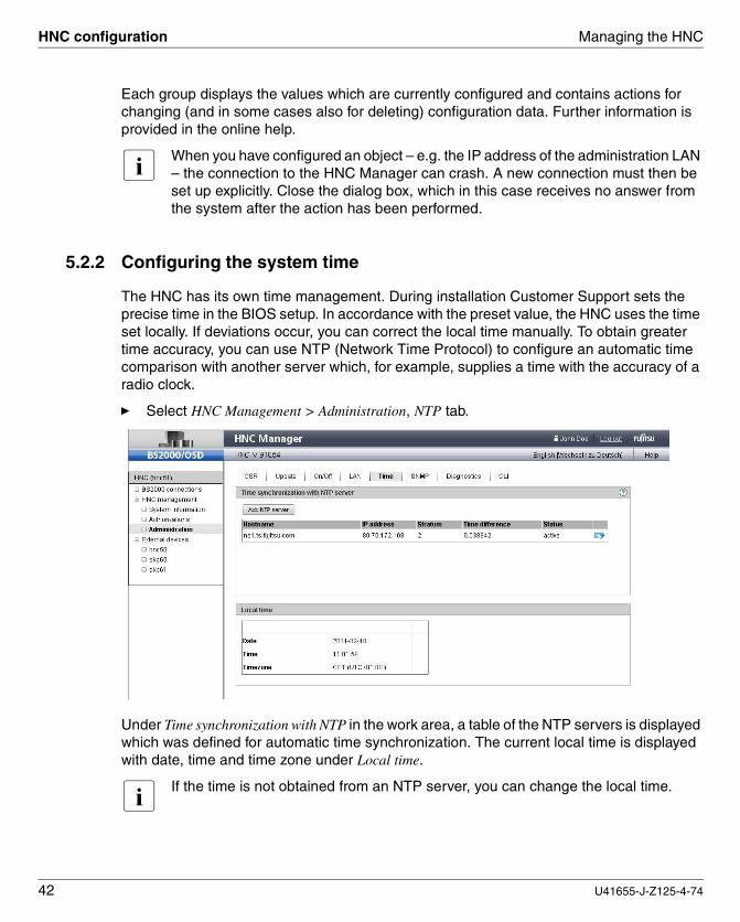
5.2.2 Configuring the system time
The HNC has its own time management. During installation Customer Support sets the precise time in the BIOS setup. In accordance with the preset value, the HNC uses the time set locally. If deviations occur, you can correct the local time manually. To obtain greater time accuracy, you can use NTP (Network Time Protocol) to configure an automatic time comparison with another server which, for example, supplies a time with the accuracy of a radio clock.
Ê Select HNC Management > Administration, NTP tab.
Under Time synchronization with NTP in the work area, a table of the NTP servers is displayed which was defined for automatic time synchronization. The current local time is displayed with date, time and time zone under Local time.
i If the time is not obtained from an NTP server, you can change the local time.

Managing the HNC HNC configuration
U41655-J-Z125-4-74 43
Dok
usch
ablo
nen
19x
24 V
ers
ion
7.4
us fü
r Fr
ameM
aker
V7
.xvo
m 0
9.02
.201
0©
co
gnita
s G
mb
H 2
001
-20
107
. Mä
rz 2
011
Sta
nd
14:4
4.28
Pfa
d: N
:\allg
em
ein
\SK
P-H
NC
\Büc
her\
Ne
u\H
NC
\en\
hnc.
k05
5.2.3 Configuring SNMP
SNMP (Simple Network Management Protocol) is a communication protocol for network, system and application management and enables the HNC to be monitored via a LAN. Monitoring is performed by management stations which communicate with the SNMP agent installed in the HNC using the SNMP protocol.
The SNMP agent supports the following MIBs:
● RFC 1213 (MIB-II)
● MIBs with private traps
Private traps are, for example, sent in the following cases:
● When the HNC is rebooted
● When switching to wait mode
● When switching back to active mode
● When sending a test trap
The following MIBs must be imported on the management station to permit the traps to be interpreted:
● /usr/share/snmp/mibs/FTS-HNCSERVER-MIB.txt
● /usr/share/snmp/mibs/SNI-MIB.txt
Access is possible, for example, with scp (secure copy).
Display SNMP configuration
Ê Select HNC Management > Administration, SNMP tab.

HNC configuration Managing the HNC
44 U41655-J-Z125-4-74
The current SNMP configuration is displayed.
Actions for the SNMP configuration
● Changing SYSNAME, SYSLOCATION and SYSCONTACT
● Adding Read community
● Removing Read community
● Adding Trap receiver
● Removing Trap receiver
● Sending Test trap (if a trap recipient is entered)
i The values for Read community and Trap receiver cannot be changed. Initially remove the value to be changed and then add it with the new value.

Managing the HNC HNC configuration
U41655-J-Z125-4-74 45
Dok
usch
ablo
nen
19x
24 V
ers
ion
7.4
us fü
r Fr
ameM
aker
V7
.xvo
m 0
9.02
.201
0©
co
gnita
s G
mb
H 2
001
-20
107
. Mä
rz 2
011
Sta
nd
14:4
4.28
Pfa
d: N
:\allg
em
ein
\SK
P-H
NC
\Büc
her\
Ne
u\H
NC
\en\
hnc.
k05
5.2.4 Managing links to external devices
You can manage links to the Web interfaces of external devices. A link is displayed in the tree structure for each device. You can thus, for example, integrate links to the other HNCs or SKPs in your computer center into the HNC Manager.
When you click a link, the corresponding Web interface opens in a new browser window provided it can be reached by the calling administration PC.
Displaying existing external devices
Ê Select External devices.
The list of the existing external devices is displayed in the lower part of the work area.
Actions for external devices
● Adding new external device
● Changing attributes of an external device
● Removing existing external device

Managing accounts Managing the HNC
46 U41655-J-Z125-4-74
5.3 Managing accounts
You manage all accounts on the HNC with the HNC Manager. You can create and modify new local accounts or delete existing accounts. When you manage accounts centrally on an LDAP server, you can configure access to an accounts database and release central accounts on the HNC, see the next section.
The sysadm account for the administrator is predefined. You can configure or permit other accounts.
All accounts are equal-ranking administrator accounts.
“Managing local accounts” on page 46 describes how you configure, change and delete local accounts.
Other accounts are released locally, but are managed centrally on an LDAP server (LDAP=Lightweight Directory Access Protocol). For information on managing these accounts, see “Managing LDAP accounts” on page 49.
The administrator can manage passwords and password attributes (e.g. for the validity period) for local accounts. The online help describes these functions for password management.
5.3.1 Managing local accounts
All accounts configured locally on the HNC are flagged with the local icon.
Display local accounts
Ê Select: HNC Management > Authorizations, Accounts tab.
A list of the existing accounts is displayed in the work area.
Managing the HNC Managing accounts
U41655-J-Z125-4-74 47
Dok
usch
ablo
nen
19x
24 V
ers
ion
7.4
us fü
r Fr
ameM
aker
V7
.xvo
m 0
9.02
.201
0©
co
gnita
s G
mb
H 2
001
-20
107
. Mä
rz 2
011
Sta
nd
14:4
4.28
Pfa
d: N
:\allg
em
ein
\SK
P-H
NC
\Büc
her\
Ne
u\H
NC
\en\
hnc.
k05
Ê To display only the local accounts, filter the Type column by selecting Local.
The local accounts are then displayed.
Actions for local accounts
● Configuring a new local account
● Changing the attributes of a local account
● Deleting a local account
● Managing a password
● Activating/deactivating a local account
5.3.2 Passwords
The passwords of the local accounts have the following attributes:Validity period, Warning time, Inactivity time:
– During the validity period, which applies from the last time the password was set, it is possible to log in without restriction.
– During the warning time, a warning is issued that the password will soon no longer be valid. However, it is possible to log in without restrictions.
– During the inactivity time, the password is no longer valid, but it is still possible to log in. Directly after a user has logged in, a request to change the password is issued.
– After the inactivity time has elapsed, the account is locked. It can be opened again from an(other) administrator account or, if necessary, by Customer Support.
– The value -1 for the Inactivity time results in the inactivity time not elapsing. – The value 99999 for the Validity period means, in practice, that you need not change the
password.

Managing accounts Managing the HNC
48 U41655-J-Z125-4-74
The figure below shows the relationship between these times.
When you create new local accounts using the HNC Manager, the passwords you specify are initially assigned the following attributes:
You can change the attributes (person-related name and comment) of your own local account at any time.
5.3.3 Configuring access to an LDAP server
You can permit access to the HNC via centrally managed accounts, see “Managing LDAP accounts” on page 49. These accounts are set up centrally on an LDAP server (Lightweight Directory Access Protocol) and are managed exclusively there. Authentication for such an account takes place on the LDAP server. The use of LDAP accounts requires access to a suitable LDAP server to be configured on the HNC.
Ê Select HNC Management > Administration, LDAP tab.
Account Validity period
Warning time
Inactivity time
Comment
<name> 60 5 7
Inactivity Minimum
Lastchange
Passwordexpired
Validity period
Account lockedLogin possible
Warning
Time (m)

Managing the HNC Managing accounts
U41655-J-Z125-4-74 49
Dok
usch
ablo
nen
19x
24 V
ers
ion
7.4
us fü
r Fr
ameM
aker
V7
.xvo
m 0
9.02
.201
0©
co
gnita
s G
mb
H 2
001
-20
107
. Mä
rz 2
011
Sta
nd
14:4
4.28
Pfa
d: N
:\allg
em
ein
\SK
P-H
NC
\Büc
her\
Ne
u\H
NC
\en\
hnc.
k05
The access parameters for the configured LDAP server are displayed in the work area. If no access is configured, the parameters are empty and only Account is predefined with ANONYMOUS.
Actions for accessing an LDAP server
● Configuring access to the LDAP server (this action is offered only if no access has yet been configured)
● Changing access to the LDAP server
● Deleting access to the LDAP server
5.3.4 Managing LDAP accounts
LDAP accounts are created in a database on the LDAP server and are managed centrally there by the administrator of the LDAP server. Management on the HNC is limited to you releasing or locking the use of an LDAP account which already exists on the local system. Only some data for the account is created on the HNC (such as login directory, the name and a comment attributes of the account).
You cannot release LDAP accounts which have the same name as a locally configured account on the local system. To use LDAP accounts you require a configured and active access to the LDAP server, see section “Managing LDAP accounts” on page 49. You obtain the necessary data from the administrator of the LDAP server.
Ê Select: HNC Management > Authorizations, Accounts tab.
The table in the work area displays all accounts which have access to the HNC. The LDAP accounts released on the HNC are flagged with the LDAP icon.
Ê To display only LDAP accounts, filter the Type column by selecting LDAP.

Managing backups (CSR) Managing the HNC
50 U41655-J-Z125-4-74
Actions for LDAP accounts
● Releasing an LDAP account
● Changing attributes of an LDAP account
● Locking an LDAP account
5.4 Managing backups (CSR)
You use a CSR backup (CSR = Configuration Save and Restore) to back up the configu-ration data in an archive. The backup archive contains the complete configuration of the system, e.g. the connections, the accounts and the NTP configuration. Each backup archive has a creation date and an archive name. Backups also exist which are created by the system, e.g. when an update is installed. These backups have self-explanatory names such as before_online_update.
Perform a CSR backup after each configuration change. With a CSR backup the configu-ration of the HNC at the time the backup was made can be restored at any time.
Ê Select HNC Management > Administration, CSR tab.
For safety’s sake you can download the CSR files to the PC. You can upload them to restore them.
i Never change the names of the CSR files, otherwise they will not be accepted when you try to upload them.
Each time a security fix, service pack or hot fix is installed, a CSR backup to a file is implicitly performed.
Displaying CSR backups
Ê Select HNC Management > Administration, CSR tab.

Managing the HNC Managing backups (CSR)
U41655-J-Z125-4-74 51
Dok
usch
ablo
nen
19x
24 V
ers
ion
7.4
us fü
r Fr
ameM
aker
V7
.xvo
m 0
9.02
.201
0©
co
gnita
s G
mb
H 2
001
-20
107
. Mä
rz 2
011
Sta
nd
14:4
4.28
Pfa
d: N
:\allg
em
ein
\SK
P-H
NC
\Büc
her\
Ne
u\H
NC
\en\
hnc.
k05
In the work area a list of the existing backup archives is displayed under Configuration data backup.
Actions for CSR backups
● Performing a CSR backup
● Restoring a backup
i Restoring a backup causes the HNC to be rebooted.
● Downloading a backup
● Uploading a backup
● Deleting a backup archive

Powering the HNC on and off Managing the HNC
52 U41655-J-Z125-4-74
5.5 Powering the HNC on and off
You can power the HNC Manager on and off remotely on a direct basis or on a time-controlled basis. The function for doing this in provided in the On/Off tab under HNC Management>Administration.
You can also shut down the HNC on a controlled basis by pressing the On/Off button on the device once briefly. When you hold down the On/Off button for a lengthy period, the HNC is switched off immediately. In this case data can be lost on the HNC. Consequently you should only do this in emergencies.
i When the HNC is shut down and not rebooted, you cannot start the HNC again remotely. You must press the On button to switch the HNC on.

U41655-J-Z125-4-74 53
Dok
usch
ablo
nen
19x
24 V
ers
ion
7.4
us fü
r Fr
ameM
aker
V7
.xvo
m 0
9.02
.201
0©
co
gnita
s G
mb
H 2
001
-20
107
. Mä
rz 2
011
Sta
nd
14:4
4.28
Pfa
d: N
:\allg
em
ein
\SK
P-H
NC
\Büc
her\
Ne
u\H
NC
\en\
hnc.
k06
6 Diagnostics and maintenanceThe HNC Manager offers the following functions for maintaining the HNC under HNC Management>Administration:
● Maintenance concept
● Updates
● Diagnostics
● System log
6.1 Maintenance concept
Customer Support performs the contractually agreed service activities, as a rule remotely as remote service. Alternatively it can also execute service activities on site on the customer premises. Hardware maintenance and the rectification of hardware problems are only possible on site.
The HNC has no separate connection to remote service. However, it can be connected indirectly via the SKP, which does have a connection to remote service.
The connection of the HNC to an SKP is as a rule implemented by means of a LAN connection (service LAN). HNCs of the type HNC-IV can also be connected via the V24 interface. Connection of the HNC to an SKP requires configuration measures and is imple-mented by Customer Support.
6.1.1 Remote service
Customer Support configures the remote service in accordance with customer wishes when system installation is performed or when the SKP/HNC is placed in service. Configu-ration can be implemented in such a manner that you as administrator, for instance, can observe all the Customer Support activities (mandatory use of a so-called shadow terminal), for details also see the SKP manual [7].

Maintenance concept Diagnostics and maintenance
54 U41655-J-Z125-4-74
Remote service ensures that a service call is sent to the service center when a problem occurs (outgoing connection). Customer Support can also establish the connection to the HNC itself (incoming connection) if it wants to correct the problem or take preventive measures (changes, updates, diagnostics, etc.).
When it is absolutely essential, as administrator you can change the remote service config-uration of the SKP or intervene in a service operation which is currently in progress. Changes to the remote service configuration on the SKP have repercussions on the service capability of your HNC.
I Important! A change to the remote service configuration must always be agreed by the admin-istrators of the SKP and of the HNC and also of the service center, otherwise the service capability of the systems you manage (HNC, SKP and S server) will be endangered. Aspects of remote service which are relevant to security are described in the Security Manual [6].
Customer Support accounts
In order to perform its work, Customer Support (remote or local) logs in under the account provided for this purpose. The protected service account in the base operating system is available to Customer Support.
6.1.2 Tasks of Customer Support
Customer Support has the following tasks:
● Diagnostics and debugging
● Software maintenance work (update)
– Providing and installing service packs
– Providing and installing hot fixes
– Providing security fixes
● Hardware maintenance work
– Upgrading software/firmware
– Model upgrades
● Increasing the number of licenses/MAC address for ZASLAN devices (to enhance the connectivity of BS2000 systems)
● Hardware upgrades

Diagnostics and maintenance Maintenance concept
U41655-J-Z125-4-74 55
Dok
usch
ablo
nen
19x
24 V
ers
ion
7.4
us fü
r Fr
ameM
aker
V7
.xvo
m 0
9.02
.201
0©
co
gnita
s G
mb
H 2
001
-20
107
. Mä
rz 2
011
Sta
nd
14:4
4.28
Pfa
d: N
:\allg
em
ein
\SK
P-H
NC
\Büc
her\
Ne
u\H
NC
\en\
hnc.
k06
6.1.3 Tasks of the customer
To perform its service activities, in some cases Customer Support requires your support on site. As the customer you have the following tasks in the maintenance concept:
● Enabling access to the HNC
– In required, have the remote service access opened by the administrator of the SKP (prerequisite for service and maintenance concept)
– Enabling access to the rack (e.g. to the local console)
● Supporting Customer Support when there are software/firmware updates for the HNC; in agreement with Customer Support, the following tasks may need to be performed:
– Transferring the updates from CD/DVD to hard disk
– Uploading service packs
– Uploading hot fixes
– Uploading and Installing security fixes
● Generating and supplying diagnostic documentation
When communicating with Customer Support, specify your HNC unambiguously with its serial number. You will find the serial number in the HNC Manager under HNC Management, System overview tab.
The serial number is YLEC<xxxxxx> (for floor stand models) and YLED<xxxxxx> (for rack models).
Note: On older hardware (HNC-IV) the serial number which you must specify is contained on the type/rating label and begins with FT followed by a sequence number.
Updates Diagnostics and maintenance
56 U41655-J-Z125-4-74
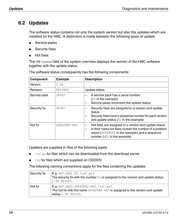
6.2 Updates
The software status contains not only the system version but also the updates which are installed on the HNC. A distinction is made between the following types of update:
● Service packs
● Security fixes
● Hot fixes
The SW version field of the system overview displays the version of the HNC software together with the update status.
The software status consequently has the following components:
Updates are supplied in files of the following types:
● iso.gz for files which can be downloaded from the download server
● iso for files which are supplied on CD/DVD
The following naming conventions apply for the files containing the updates:
Component Example Description
Version 2.0A
Revision REV=003 Update status
Service pack SP=01 – A service pack has a serial number (01 in the example)
– Service packs increment the update status
Security fix SF=01 – Security fixes are assigned to a version and update status
– Security fixes have a sequence number for each version and update status (01 in the example)
Hot fix A0562581-H01 – Hot fixes are assigned to a version and update status– In their name hot fixes contain the number of a problem
report (A0562581 in the example) and a sequence number (H01 in the example)
Security fix E.g. HV2.0A01.01.iso[.gz] The security fix with the number 01 is assigned to the version and update status 2.0A REV=01.
Hot fix E.g. HV2.0A01.A0562581-H01.iso[.gz] The hot fix with the name A0562581-H01 is assigned to the version and update status 2.0A REV=01.
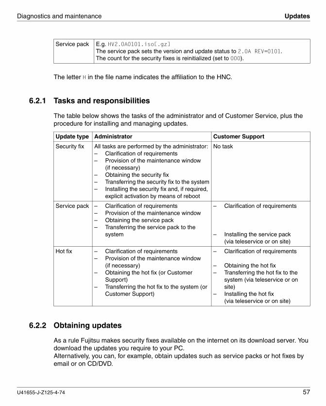
Diagnostics and maintenance Updates
U41655-J-Z125-4-74 57
Dok
usch
ablo
nen
19x
24 V
ers
ion
7.4
us fü
r Fr
ameM
aker
V7
.xvo
m 0
9.02
.201
0©
co
gnita
s G
mb
H 2
001
-20
107
. Mä
rz 2
011
Sta
nd
14:4
4.28
Pfa
d: N
:\allg
em
ein
\SK
P-H
NC
\Büc
her\
Ne
u\H
NC
\en\
hnc.
k06
The letter H in the file name indicates the affiliation to the HNC.
6.2.1 Tasks and responsibilities
The table below shows the tasks of the administrator and of Customer Service, plus the procedure for installing and managing updates.
6.2.2 Obtaining updates
As a rule Fujitsu makes security fixes available on the internet on its download server. You download the updates you require to your PC. Alternatively, you can, for example, obtain updates such as service packs or hot fixes by email or on CD/DVD.
Service pack E.g. HV2.0A0101.iso[.gz] The service pack sets the version and update status to 2.0A REV=0101. The count for the security fixes is reinitialized (set to 000).
Update type Administrator Customer Support
Security fix All tasks are performed by the administrator:– Clarification of requirements– Provision of the maintenance window
(if necessary)– Obtaining the security fix– Transferring the security fix to the system– Installing the security fix and, if required,
explicit activation by means of reboot
No task
Service pack – Clarification of requirements– Provision of the maintenance window– Obtaining the service pack– Transferring the service pack to the
system
– Clarification of requirements
– Installing the service pack(via teleservice or on site)
Hot fix – Clarification of requirements– Provision of the maintenance window
(if necessary)– Obtaining the hot fix (or Customer
Support)– Transferring the hot fix to the system (or
Customer Support)
– Clarification of requirements
– Obtaining the hot fix– Transferring the hot fix to the
system (via teleservice or on site)
– Installing the hot fix(via teleservice or on site)

Updates Diagnostics and maintenance
58 U41655-J-Z125-4-74
6.2.3 Managing updates
For software updates to be installed, they must be available on the HNC. You can transfer the following types of update to the HNC and manage them there:
● Security fix
A security fix contains all updates for the Linux-based operating system which are relevant to security and have appeared since the last security pack. Security fixes protect the system concerned against, for instance, unauthorized access or attacks from outside. Whether you install current security fixes depends on your security requirements and on whether the HNC can only be accessed via the separate admin-istration LAN or also from the outside. Functional use of the HNC is also guaranteed without current security fixes.
● Service pack
A service pack contains a collection of corrections for the Linux-based operating system. It contains all previous service packs and security fixes, as well as selected hot fixes. It is installed by Customer Support.
● Hot fix
A hot fix contains a correction which enables an urgent problem in the system to be rectified as quickly as possible. It is installed by Customer Support.
6.2.4 Actions for updates
You can execute the following actions for the various update types:
Ê Select HNC Management > Administration, Update tab.
The actions are performed in a similar manner for all update types. When an update is installed, a configuration data backup (CSR backup) is explicitly transferred to the tar file before_online_update (with timestamp). Consequently only the last configuration data backup is retained. Detailed information is provided in the online help.
Update type Transferupdate
from CD/DVD
Displayupdate
DisplayRelease Notice
Uploadupdate
Installupdate
Security fix X X X X X
Hot fix X X X X
Service pack X X X X

Diagnostics and maintenance Assisting Customer Support
U41655-J-Z125-4-74 59
Dok
usch
ablo
nen
19x
24 V
ers
ion
7.4
us fü
r Fr
ameM
aker
V7
.xvo
m 0
9.02
.201
0©
co
gnita
s G
mb
H 2
001
-20
107
. Mä
rz 2
011
Sta
nd
14:4
4.28
Pfa
d: N
:\allg
em
ein
\SK
P-H
NC
\Büc
her\
Ne
u\H
NC
\en\
hnc.
k06
6.3 Assisting Customer Support
The HNC does not have its own remote service connection. Instead, this is implemented by a correct link to an SKP which has its own remote service connection. Consequently the current service capability of the HNC depends on the SKP.
To assist Customer Support it may some cases be necessary to change the configuration of the access on the SKP (e.g. by opening the access) or to intervene in a Customer Support operation which is currently in progress.
The corresponding functions are available to the administrator (and to a lesser extent to the operator) on the SKP. Details are provided in section "Assisting Customer Support “of the SKP manual [7].
i A change to the remote service configuration must always be agreed by the admin-istrators of the SKP and of the HNC and also of the service center, otherwise the service capability of the systems you manage (HNC, SKP and S server) will be endangered.
Aspects of remote service which are relevant to security are described in the Security Manual [6].

Diagnostic data Diagnostics and maintenance
60 U41655-J-Z125-4-74
6.4 Diagnostic data
When a fault occurs, it makes sense to generate diagnostic data and to send this data to the service center for evaluation. The diagnostic file is a compressed tar archive and contains important logging, trace and configuration files.
Ê Select HNC Management > Administration, Diagnostics tab.
The name of an existing diagnostic file is displayed in the work area under File name: DIAGtar.<date>.<time>.gz.
A “-” instead of a file name shows that no diagnostic data has been created yet.
Actions for diagnostic documentation
● Generating new diagnostic data
V Caution: An existing diagnostic file will be overwritten. If required, download the existing file to your local system beforehand.
● Downloading diagnostic data to the PC

Diagnostics and maintenance System log (audit log)
U41655-J-Z125-4-74 61
Dok
usch
ablo
nen
19x
24 V
ers
ion
7.4
us fü
r Fr
ameM
aker
V7
.xvo
m 0
9.02
.201
0©
co
gnita
s G
mb
H 2
001
-20
107
. Mä
rz 2
011
Sta
nd
14:4
4.28
Pfa
d: N
:\allg
em
ein
\SK
P-H
NC
\Büc
her\
Ne
u\H
NC
\en\
hnc.
k06
6.5 System log (audit log)
The audit log function logs on the HNC all actions which are performed using the HNC Manager or the CLI and cause the configuration or status to change. Only pure outputs are not logged.
Logging takes place automatically. Entries are written to a file with the name auditlog. The contents of the log file are backed up and compressed each month or when the maximum size of 10 MB is exceeded. The backed-up files have the name auditlog.<yyyymmdd>.bz2 (yyyymmdd: timestamp in the format year-month-day). A maximum of 36 log files are activated, which means that as a rule an overview is provided of a 3-year period.
You can view the log files of audit log and download them to your PC:
Ê Select HNC Management > System information, Audit log tab.
Structure of audit log
Each internal CLI call which is executed for an action generates its own log entries (the start and the result). Consequently there are often several entries in the log for one action.
A row in the audit log has the following structure:
<timestamp> <system name> <account>_[Web ID] <entry type> <command text>
timestamp Time of the entry in the format <yyyymmdd.hhmmss>
system name Name of the system on which the action was executed.
account Account under which the action was executed. The HNC Manager (GUI) runs under the account wwwrun. Consequently the Web ID (GUI account + IP address) is appended in this case.
entry type Describes the action and can have the following values:
start Start of an action at CLI level
sqmstart Start of an action at GUI level

System log (audit log) Diagnostics and maintenance
62 U41655-J-Z125-4-74
rc=RC Result of an action at CLI level
sqmrc=RC Result of an action at GUI level
access Login at CLI level
sqmaccess Logout at GUI level
status Status message of a component
entry Internal call
command text Information on the action
CLI: The command is logged with all parameters.
GUI: The actions is logged as in the GUI and in the language selected.
Exceptions: Data such as passwords which is relevant to security is not logged.
A simple action consists of 2 rows, the start of the action (start) and the result (rc=). A complex action nests simple entries according to the internal calls.
Example
The user sysadm changes his/her password:20110128.120644 donau wwwrun_217.9.101.18_sysadm sqmstart Action=Password management; Account=cogadm; Password=******; 20110128.120644 donau wwwrun start passwd -S cogadm 20110128.120644 donau wwwrun rc=0 passwd -S cogadm 20110128.120644 donau wwwrun start passwd --stdin cogadm 20110128.120644 donau wwwrun rc=0 passwd --stdin cogadm 20110128.120644 donau wwwrun_217.9.101.18_sysadm sqmrc=0 Action=Password management; Account=cogadm; Password=******; --> Password for account cogadm successfully changed.
Actions for audit log
● View individual audit log files; filtering is possible
● Download audit log to the PC

U41655-J-Z125-4-74 63
Dok
usch
ablo
nen
19x
24 V
ers
ion
7.3
2us
für
Fra
me
Mak
er
V7.
xvo
m 2
8.0
3.20
07©
cog
nita
s G
mbH
200
1-2
007
7. M
ärz
201
1 S
tan
d 14
:44.
28P
fad:
N:\
allg
em
ein
\SK
P-H
NC
\Büc
her\
Neu
\HN
C\e
n\h
nc.li
t
Related publications
Ordering manuals
The manuals are available as online manuals, see http://manuals.ts.fujitsu.com, or in printed form which must be paid and ordered separately at http://manualshop.ts.fujitsu.com.
[1] BS2000/OSD-BC System InstallationUser Guide
[2] BS2000/OSD-BCIntroductory Guide to Systems SupportUser Guide
[3] VM2000 Virtual Machine SystemUser Guide
[4] openNet Server (BS2000/OSD)BCAM User Guide
[5] BS2000/OSD-BC Commands User Guide
[6] SQ Server/SKP/HNC Security ManualUser Guide
[7] SKPUser Guideh

Related publications
64 U41655-J-Z125-4-74

U41655-J-Z125-4-74 65
Dok
usch
ablo
nen
19x
24 V
ers
ion
7.3
2de
für
Fra
me
Mak
er V
7.x
vom
28.
03.2
007
© c
ogn
itas
Gm
bH
20
01-2
007
7. M
ärz
201
1 S
tand
14
:44.
28P
fad
: N:\a
llgem
ein
\SK
P-H
NC
\Büc
her\
Ne
u\H
NC
\en\
hnc.
six
Index
Aaccess
remote service 17account 21, 46
activating 47changing 48changing attributes 47configuring a new account 47deactivating 47deleting 47management 46managing LDAP 49sysadm 46
administration LAN 15applet 19audit log 61
actions 62structure 61
auditLog (command) 32
BBCAM 36BS2000 connections 15, 33BS2000 device (emulated), properties 35BS2000 MAC address 35BS2000 MN, LOCLAN device 36
Cchanges 8channel type S see ESCONCLI 19, 31, 32
closing access 31opening access 31terminating access 31
cli_info (command) 32
commandauditLog 32cli_info 32displaying, cli_info 32init 32
Command Line Interface 19, 31, 32Configuration Save and Restore 50configuration, HNC 41connection type
LOCLAN 14ZASLAN 14
Cookies 19CSR backup 51
deleting archive 51displaying 50downloading 51managing 50performing 51uploading 51wrestoring 51
Customer Support 19tasks 54
Ddatabase
for accounts 46, 49default account, password 21default gateway 41device
external 45diagnostic data
generating 60dialog box 25Domain Name System 41download server 56

Index
66 U41655-J-Z125-4-74
Eerror
in the HNC Manager 30ESCON 11ESCON controller 13, 35external device, link in HNC Manager 45external device, link in SQ Manager 45
FFibre Channel 35Fibre Channel (FC) 11, 13filter 27
GGraphical User Interface 19GUI 19
Hhardware, HNC 16header area 23HNC
basic mode of operation 13configuration 41hardware 16maintenance 53powering on/off 52
HNC Managererror 30interface 22language 20logging in 20logging out 21
hot fix 50, 56, 58
Iinactivity time 47init (command) 32IP address
making known to BCAM 36
JJava Runtime Environment 19JavaScript 19
LLAN interface (X2000) 41language options 23LDAP
configuring access to server 48managing account 49
LDAP server 46licences for open source software 2Lightweight Directory Access Protocol 46Linux version 18LOCLAN 14logging in
CLI 31HNC Manager 20
logging outCLI 31HNC Manager 21
login window 21
MMAC address 14main window 23maintenance, HNC 53mnemonic 15mode of operation of the HNC 13
Nnavigation 27notational conventions 9
Oonline help 28open source software
licences 2
Pparameter area 25password 21
managing 47PC 19powering on and off 52Primergy server 16

Index
U41655-J-Z125-4-74 67
Dok
usch
ablo
nen
19x
24 V
ers
ion
7.3
2de
für
Fra
me
Mak
er V
7.x
vom
28.
03.2
007
© c
ogn
itas
Gm
bH
20
01-2
007
7. M
ärz
201
1 S
tand
14
:44.
28P
fad
: N:\a
llgem
ein
\SK
P-H
NC
\Büc
her\
Ne
u\H
NC
\en\
hnc.
six
Rread community 44remote service 17revision 56role concept 46
SS server 9security fix 18, 50, 56, 58server
download 56LDAP 48SNMP 43
Service LAN 15service pack 50, 56, 58session 22session ID 22Simple Network Management Protocol (see
SNMP) 43SLAN 13SLAN (shared LAN) 14SNMP 43SOF file 37software
status 56update 56
sorting, table 27sysadm (administrator role) 46system
log 61version 56
Ttab 23
CSR 50table
sorting 27tabs 23terminal window
closing 31opening 31
time management 42time synchronization 42title bar 23
trap receiver 44tree structure 23
Uunit ID 36update 56
obtaining 57responsibilities 57tasks 57
update status 56uploading
CSR backup 51user account, see accountuser management 46
Vvalidity period 47VCA 11, 15Virtual Channel Adapter 11, 15virtual WWPN 36
Wwarning time 47window types 22work area 23WWPN (World Wide Port Name) 13, 36
ZZASLAN 14

Index
68 U41655-J-Z125-4-74