Embed Size (px)
Citation preview
April 8, 2011 HN FAQ Memo, Version 3.0 Page 1 of 108
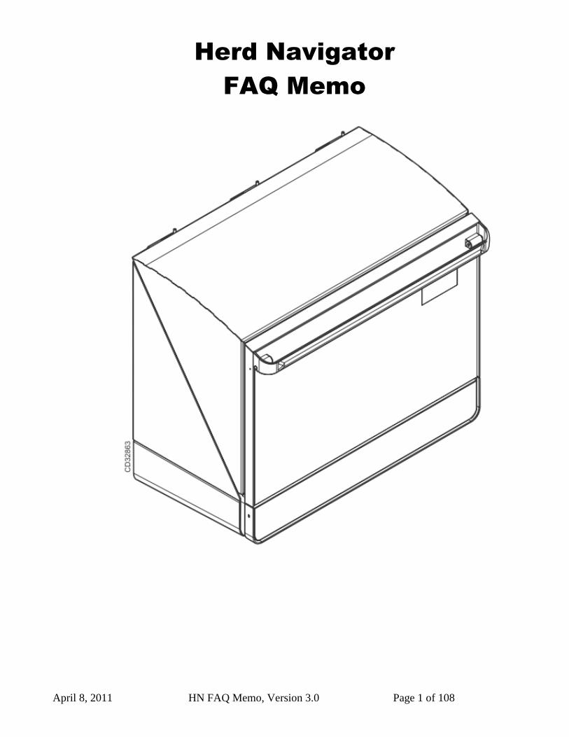
Herd Navigator
FAQ Memo
April 8, 2011 HN FAQ Memo, Version 3.0 Page 2 of 108
Table of Contents
1 Introduction. ............................................................................................................................................. 4 1.1 Revision History .............................................................................................................................. 4
2 Trouble shooting. ..................................................................................................................................... 6
2.1 HSM error messages: ....................................................................................................................... 6 2.1.1 AI State = Wait ............................................................................................................................ 6 2.1.2 DosageLineOpenTimeout ............................................................................................................ 6 2.1.3 DosageMissed .............................................................................................................................. 6 2.1.4 BD1Posttimeout ........................................................................................................................... 6
2.1.5 BD5PostSampleTimeout .............................................................................................................. 7 2.1.6 BD5PresampleTimeout ................................................................................................................ 7
2.1.7 BD3 Air ........................................................................................................................................ 7 2.1.8 BD3PresampleTimeout ................................................................................................................ 7 2.1.9 EL_AC_OFF_EXTERNAL_BUS ............................................................................................... 7 2.1.10 Heart beat : AC ........................................................................................................................ 8
2.1.11 Heart beat : AI .......................................................................................................................... 8 2.1.12 Heart beat : SI .......................................................................................................................... 8
2.1.13 Heart beat : DSM ..................................................................................................................... 8 2.1.14 Heart beat: PC .......................................................................................................................... 8 2.1.15 Incubator 90% RH / or visible signs of liquid in the IM.......................................................... 8
2.1.16 Quarantine ................................................................................................................................ 9 2.2 VMS and VMS sampler errors in HSM. ........................................................................................ 10
2.3 Trouble shooting on samplers. ....................................................................................................... 12 2.4 Using the “Sample all” function in the AC. ................................................................................... 14
3 Best Practices / How do I. ...................................................................................................................... 15 3.1 Sample Intake ................................................................................................................................. 15
3.1.1 Activate Sample simulation in SI. (Parlour only and needs Vacuum)....................................... 15
3.1.2 How to simulate samples trough SI : ......................................................................................... 17 3.1.3 How to manually test Safty/flush and Filter valve in SI (Needs Vacuum): ............................... 18
3.1.4 Start Cleaning from SI menu : ................................................................................................... 19 3.1.5 Adjustment of Index on SI Multivalve. ..................................................................................... 20 3.1.6 Mounting the Tube for Milkpump in the Sample Intake. .......................................................... 23
3.1.7 Correct mounting of the Air detector assembly, BD1,BD5,BD3 and BD4. .............................. 27 3.2 Analyzer Instrument (AI). .............................................................................................................. 36
3.2.1 Procedure for complete cleaning of milk transport system between SI and AI. ........................ 36 3.2.2 Measuring the water amounts during AI cleaning. .................................................................... 45
3.2.3 Adjustment of dosage needle clean position. ............................................................................. 48 3.2.4 Howto – Close Hatch Manualy. ................................................................................................. 52 3.2.5 Replacing Flow and Dosage module + 2 years AI service. ....................................................... 55
3.3 HN and Delaval C200 parlour cleaning. ........................................................................................ 58 3.3.1 Abbreviations ............................................................................................................................. 58
3.3.2 Herd Navigator and C200 installation in the parlour. ................................................................ 58 3.3.3 C200 and HN cleaning sequence. .............................................................................................. 59
3.3.4 C200 parametre .......................................................................................................................... 60 3.3.5 AC and SC parameters ............................................................................................................... 60 3.3.6 SI parameter ............................................................................................................................... 61
3.3.7 C200 parameters from diff. HN Farms. ..................................................................................... 62
April 8, 2011 HN FAQ Memo, Version 3.0 Page 3 of 108
3.4 Sampler. ......................................................................................................................................... 64 3.4.1 Recalibration of sampler transfer time. ...................................................................................... 64
4 INFO: ..................................................................................................................................................... 65 4.1 Menu overview for the Sample Intake, (SI) ................................................................................... 65
4.2 Menu overview for the Analyser instrument (AI) ......................................................................... 67 4.3 Menu overview for the Analysis controller (AC) .......................................................................... 72 4.4 Connecting AI to the drain with pn:60045416............................................................................... 74 4.5 Tube Connections on Sampler version II ....................................................................................... 75 4.6 Replacing the CIP box in the Parlour/VMS Sample Intake (upgrade). ......................................... 77
5 Appendices: ............................................................................................................................................ 79 5.1 AC .................................................................................................................................................. 79
5.1.1 Remote connection to AI or SI trough AC whit ethernet : ........................................................ 79 5.1.2 AC basis settings IP address (Reset / New instalation) (VMS / Parlour) ................................. 80
5.1.3 Update orders in AC / HN service controller. ............................................................................ 81 5.2 Updating firmware in HN Units..................................................................................................... 83
5.2.1 Tools Needed : ........................................................................................................................... 83
5.2.2 Preparation and Connection to the Unit ..................................................................................... 83 5.2.3 Programming the Unit ................................................................................................................ 85
5.3 Updating the AC, AI, or SI boards with new version of the bootloader. ....................................... 89 5.4 Sampler programming guide :........................................................................................................ 92
5.4.1 Decimal - hexadecimal conversion table ................................................................................... 98 5.5 Updating FPGA software on HN2 AI ............................................................................................ 99
5.6 HN2 AI startup settings................................................................................................................ 102 5.6.1 Step 1 : Connect AI to the Ethernet. ........................................................................................ 102
5.6.2 Step 2: Entering the rest of the Ethernet settings in the AI configuration. .............................. 103 5.6.3 Step 3 : Use the AC‟s Web interface to setup AC to use HN-2 AI. ........................................ 105
5.6.4 Step 4 : Setup the Alcom address for the AI in Sample Intake to same address as the AC..... 108
April 8, 2011 HN FAQ Memo, Version 3.0 Page 4 of 108
1 Introduction. This is the third version of a Memo intended to be used by service technicians working with the Herd Navigator system. This third version includes new chapters as well as some existing chapters are updated, mainly to cover the HN version 2 systems as well. However the process of constantly developing and filling the memo with the necessary information, will continue. We are therefore very interested in getting your feedback, on both the things that are in the Memo, and the things that you miss in the Memo. In this way we can help each other to develop a “handbook” allowing all Herd Navigator Technicians to have the necessary information and guidelines to do their job the best way. The Memo contains four main Chapters A trouble shooting section: with description of error messages, and the possible causes and actions. In this section there is references to relevant chapters in the next section. A best practice / How do I section: This section has descriptions of the different procedures for working with and operating the Herd Navigator systems. This includes things as cleaning, adjustments, assembly instructions, simulating operation for test purposes. Ect. An Info section: This section has useful information on upgrades made on the system, and where to find the latest technical diagrams ect. An Appendices section: This section has chapters on how to download firmware, list of settings ect.
1.1 Revision History
Date Revision Responsible Comments
2010-09-23 1.1 PEC 1. released version
2010-12-10 2.0 PEC 2.1.15 incubator 90%.... updated.
2.1.16 Quarantine, updated.
2.2 VMS and VMS sample …., added.
2.4 Using sample all function , added
3.1.6 Mounting tube for milkpump, added.
3.1.7 Air detector , updated.
3.2.1. procedure for cleaning….updated
3.2.2. Measuring water amounts.. added.
3.2.3 Cleaning position ……, added.
3.3 HN /C200 cleaning, now in English.
4.1 Menu overview SI, added.
4.2 Menu overview AI, added.
4.3 Menu overview AC, added.
4.5 Connecting the AI to drain, added.
4.6 Tube connections on sampler verII, added
4.7 Replacing the SI CIP box …, added.
5.1.3 Update orders in AC, added.
5.2 updating Firmware in HN units, added.
5.3 updating boards with bootloader, added.
Mounting of BD on detergent, removed.
General minor error corrections.
2011-04-08 3.0 PEC 3.1.6 Mounting tube for milkpump, updated.
3.2.1 Procedure for cleaning……, updated.

April 8, 2011 HN FAQ Memo, Version 3.0 Page 5 of 108
3.2.2 measuring the water …….,updated
3.2.3 Adjustment of clean pos….,updated.
3.4.1 Recalibration of sampler transf…, added.
5.5 Updating FPGA software on HN2.., added.
5.6 HN2 AI startup settings, added.
April 8, 2011 HN FAQ Memo, Version 3.0 Page 6 of 108
2 Trouble shooting.
2.1 HSM error messages:
2.1.1 AI State = Wait
Description: An error In the AI has occurred causing the AI to restart, after restart the AI is unable to initialize all
modules and go to standby mode.
Causes / Actions: Restart AI, if it doesn’t go to standby mode: Open AI, restart again and check witch module that
doesn’t initialize. Look for errors on that module.
2.1.2 DosageLineOpenTimeout
Description: The SI has sent a sample to the AI. The AI has not responded to that, and the sample will timeout.
Causes / Actions: Check if AI is in Standby or Auto mode: if not restart AI, if it doesn’t go to standby mode: Open
AI, restart again and check witch module that doesn’t initialize. Look for errors on that module.
2.1.3 DosageMissed
Description: The SI has sent a sample to the AI. The AI has not responded to that, and the sample will timeout.
Causes / Actions: Check if AI is in Standby or Auto mode: if not restart AI, if it doesn’t go to standby mode: Open
AI, restart again and check witch module that doesn’t initialize. Look for errors on that module.
2.1.4 BD1Posttimeout
Description: The backend of the sample send from SI has not been detected by BD1 within the expected timeslot.
(the front end has been detected.)
Causes / Actions: Check for leaks in the Safety/flush valve and the filter.
Check that the Tube from SI to AI has the correct length, and that the BD1 is placed at correct distance from SI. References: 2.1.3 How to manually test Safty/flush and Filter valve in SI (Needs Vacuum): 2.1.2 How to simulate samples trough SI :
April 8, 2011 HN FAQ Memo, Version 3.0 Page 7 of 108
2.1.5 BD5PostSampleTimeout
Description: The backend of the sample send from SI has not been detected by BD5 in the expected timeslot. (the
front end has been detected.)
Causes / Actions: Check filter operation, if filter doesn’t lift, no air will be present in the tube after the sample.
Check mounting of BD5. Check tube length is correct between MV arm and Flush valve. References: 2.1.7Correct mounting of the Air detector assembly
2.1.6 BD5PresampleTimeout
Description: The sample send from SI has not been detected by the BD5 within the expected timeslot.
Causes / Actions: IF this error occurs together with BD3 errors, look for actions at BD3 errors.
Else it could be caused by leaking milk pump tube (pressure side) or check filter and safety/flush valves.
References: 2.1.3 How to manually test Safty/flush and Filter valve in SI (Needs Vacuum): 2.1.2 How to simulate samples trough SI :
2.1.7 BD3 Air
HSM Error message:
Description: Sample detected at BD3 but sample has been to short or there has been air bubbles in the sample.
Causes / Actions: Check MV arm tube for leakage. Check positioning of MV arm. Check lift of MV arm.
References: 2.1.5 Adjustment of Index on SI Multivalve.
2.1.8 BD3PresampleTimeout
Description: No sample has been detected at BD3 within the expected timeslot.
Causes / Actions: Test milking at farm, thus no milk samples taken at all.
Error in milk pump or milk pump tube, in the SI. Error in safety flush valve. No milk sent from sampler. Mainline out valve on AI clogged. References: 2.1.3 How to manually test Safty/flush and Filter valve in SI (Needs Vacuum): 2.1.2 How to simulate samples trough SI :
2.1.9 EL_AC_OFF_EXTERNAL_BUS
Description: The Alcom node no. that the AC uses is used by another unit on the Alcom bus.
Causes / Actions: Change Alcom node No. For AC on the external Canbus (alcom)
April 8, 2011 HN FAQ Memo, Version 3.0 Page 8 of 108
2.1.10 Heart beat : AC
Description: No connection to AC,
Causes / Actions: Restart unit. Check farm internet connection.
2.1.11 Heart beat : AI
Description: No connection to AI,
Causes / Actions: Restart unit. Check farm internet connection.
2.1.12 Heart beat : SI
Description: No connection to SI,
Causes / Actions: Restart unit. Check farm internet connection.
2.1.13 Heart beat : DSM
Description: No connection to DSM software,
Causes / Actions: Restart pc. Check farm internet connection.
2.1.14 Heart beat: PC
Description: No connection to the DSM pc,
Causes / Actions: Restart pc. Check farm internet connection.
2.1.15 Incubator 90% RH / or visible signs of liquid in the IM.
Description: The Too high humidity in the AI incubator compartment. Probably caused by leakage in the
dosage or waste system in the AI. If there is visible liquid in the Incubator, it can be milk, water, diluent or
a mix of the three.
Actions:
-Open the AI.
-Clean of any visible liquid in the Incubator compartment.
-Check for leakage and fix or replace any broken tubes or connections.
-Leakage in the dosage system can sometimes only be visible with working pressure on the tubes, to get
this:
-Request a prime of diluent from the AI display, and check for leaks in the diluent system.
-Request a CIP from the AI display, and check for leaks in the mainline, and dosage line.
-Check that the waste tube has a slope all the way, otherwise it can overflow.
-Clean the AI thoroughly for any residues of milk/diluent/water. If the incubator disk needs cleaning,
remove it and clean it with a soft brush and lukewarm soap water.
-If the humidity is high in the incubator after cleaning, a bag of desicant (used to load in storage) can be
placed in the waste container. Instruct the farmer to remove the bag after next milking session.
April 8, 2011 HN FAQ Memo, Version 3.0 Page 9 of 108
2.1.16 Quarantine
Description: The quarantine indicates that there is a problem with the dosage system in the Herd
Navigator.
If there is a problem with the dosage system it is likely that the dosage volume will be to little or no dosage
at all. This situation will affect the measurements of all four constituents, leading to false reactions in the
bio-models, and leading to false alarms. The LDH sticks is sensitive to the dosage volume and no or little
dosage will show up as very low LDH, and out off range results. To avoid false input to the bio-models ,the
level of the measurements on the LDH sticks is continuously monitored. If the general level of LDH
(measured over a number of samples) drops, the Quarantine function gets active. The quarantine function
will then make sure that all these results are quarantined and not used in the Bio-models. Furthermore the
quarantine function will stop measuring on BHB, Urea and progesterone sticks. The monitoring of the LDH
measurements will continue, and the quarantine function will detect if the results will revert to normal
levels again. After a given number of good LDH results the quarantine will be cancelled and the
measurement on all constituents will continue.
Most often the quarantine requires a visit by the service technician to clean the complete dosage system.
Causes / Actions: Leaks in dosage system, or tubes clogged.
Inspect all tubes and clean the complete milk line from SI to AI.
Note that a given number of “good” samples are required after a quarantine, before the quarantine is
cancelled.
Reference: 2.2.1 Procedure for complete cleaning of milk transport system between SI and AI.
April 8, 2011 HN FAQ Memo, Version 3.0 Page 10 of 108
2.2 VMS and VMS sampler errors in HSM.
TransferFailed: (Bd4.xPresampleTimeout, x=TubeNo.)
1. Error in VMS sampler, no milk from the sampler to the transfer tube.
2. Wrong pressure in transfer tube, caused by milking pressure in the VMS.
3. If on a new installation, it could be caused by a wrong setting in the ”detect Window” in AC. The SI will
try to detect the lead end of the sample at a time where the sample is either before or after Bd4.x.
4. Incorrect mounting of Bd4.x, or Bd4.x has been exposed to water.
Bd4PostsampleTimeout: (only warning)
1. Sample in VMS sample container is to big.
2. Too high pressure resistance in the transfer tube, causing decreased performance of milk tube pump.
could be caused by pinched tube..
3. Incorrect mounting of Bd4.x, or Bd4.x has been exposed to water.
Bd4PostsampleTimeout+ Bd5PostsampleTimeout: (only warnings)
1. Incorrect mounting of Bd4.x, or Bd4.x has been exposed to water.
Bd4PostsampleTimeout+ Bd5PostsampleTimeout+ Bd1PostsampleTimeout:
1. Incorrect mounting of Bd4.x, or Bd4.x has been exposed to water.
Bd4Air:
1. Sample in VMS sample container is too little.
2. Air bubbles in the sample.
Bd5PresampleTimeout:
1. Lead end of sample has been detected by Bd4.x, but no sample entered BD5. Could be caused by defect
in SI stop valve (pinch valve) or missing sample from VMS.
2. Incorrect mounting of Bd5, or Bd5 has been exposed to water.
Bd5Air:
1. Sample in VMS sample container is to little.
2. Air bubbles in the sample..
Bd5PostsampleTimeout:
1. Incorrect mounting of Bd4.x, or Bd4.x has been exposed to water.
2. Incorrect mounting of Bd5, or Bd5 has been exposed to water.
3. Coatings in main line tube (ø2mm) causing malfunction of Bd5, could be caused by cleaning problems.
Bd5PostsampleTimeout+ Bd1PostsampleTimeout:
1. Incorrect mounting of Bd4.x, or Bd4.x has been exposed to water.
2. Incorrect mounting of Bd5, or Bd5 has been exposed to water.
3. Coatings in main line tube (ø2mm) causing malfunction of Bd5, could be caused by cleaning problems.
Bd1PostsampleTimeout:
April 8, 2011 HN FAQ Memo, Version 3.0 Page 11 of 108
1. Incorrect mounting of Bd1, or Bd1 has been exposed to water.
2. Coatings in main line tube (ø2mm) causing malfunction of Bd5, could be caused by cleaning problems.
Ready For CIP Timeout:
1. Error in heating the CIP containers in the SI
Ready For CIP Timeout+Fill Timeout:
1. Error in water supply or water level sensors in CIP containers in SI
Fill Timeout:
1. Error in water supply or water level sensors in CIP containers in SI
No AI-CIP water:
1. Error in water supply or water level sensors in CIP containers in SI
Bd5 eller Bd1 CIP Air Detect:
1. Air has been detected in Bd5 or Bd1 during cleaning,
2. Check HSM->Climate->cleaning diagram below. to see if it is a bubble or missing water.
3. If it is a bubble it is OK
4. if missing water ict could be an error in water supply or water level sensors in CIP containers in SI
SI Detergent Empty:
1. Empty Detergent container, or an air bubble has been detected by the detergent Bd.
April 8, 2011 HN FAQ Memo, Version 3.0 Page 12 of 108
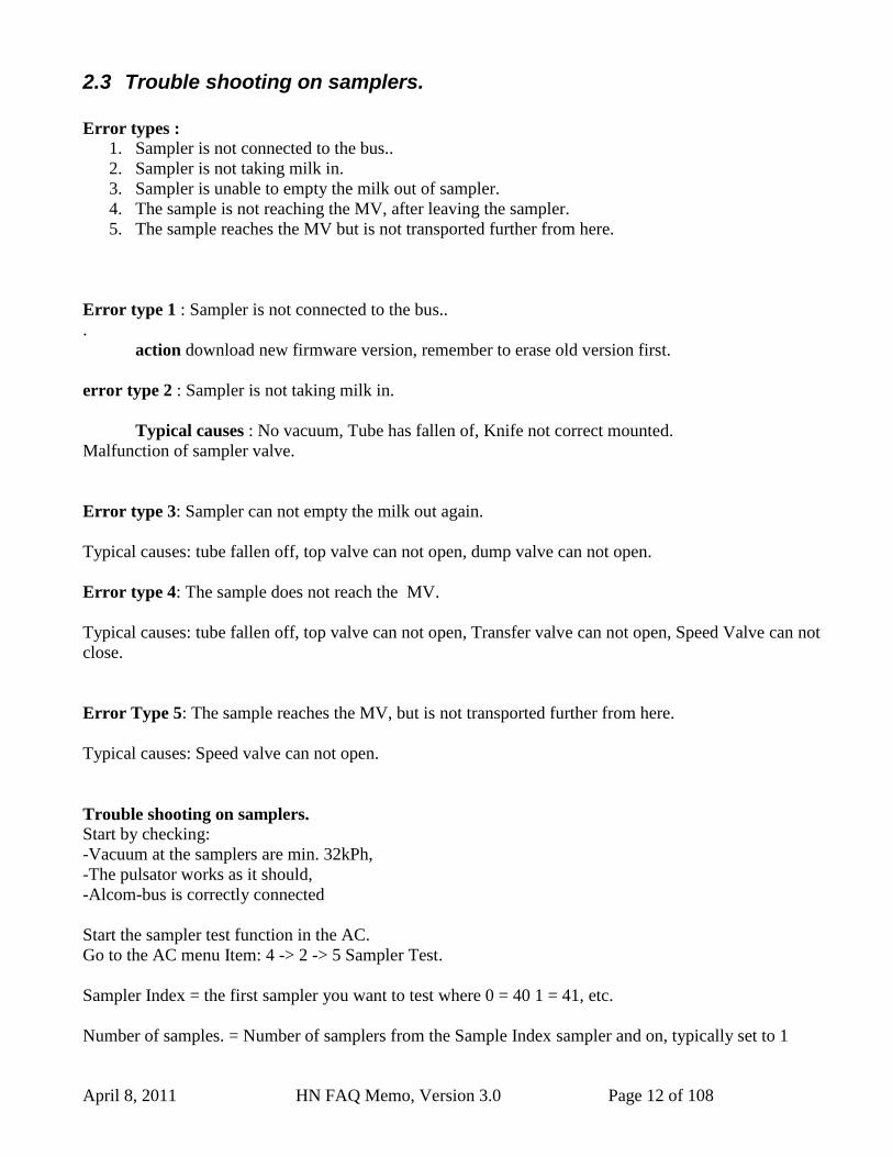
2.3 Trouble shooting on samplers.
Error types :
1. Sampler is not connected to the bus..
2. Sampler is not taking milk in.
3. Sampler is unable to empty the milk out of sampler.
4. The sample is not reaching the MV, after leaving the sampler.
5. The sample reaches the MV but is not transported further from here.
Error type 1 : Sampler is not connected to the bus..
.
action download new firmware version, remember to erase old version first.
error type 2 : Sampler is not taking milk in.
Typical causes : No vacuum, Tube has fallen of, Knife not correct mounted.
Malfunction of sampler valve.
Error type 3: Sampler can not empty the milk out again.
Typical causes: tube fallen off, top valve can not open, dump valve can not open.
Error type 4: The sample does not reach the MV.
Typical causes: tube fallen off, top valve can not open, Transfer valve can not open, Speed Valve can not
close.
Error Type 5: The sample reaches the MV, but is not transported further from here.
Typical causes: Speed valve can not open.
Trouble shooting on samplers.
Start by checking:
-Vacuum at the samplers are min. 32kPh,
-The pulsator works as it should,
-Alcom-bus is correctly connected
Start the sampler test function in the AC.
Go to the AC menu Item: 4 -> 2 -> 5 Sampler Test.
Sampler Index = the first sampler you want to test where 0 = 40 1 = 41, etc.
Number of samples. = Number of samplers from the Sample Index sampler and on, typically set to 1
April 8, 2011 HN FAQ Memo, Version 3.0 Page 13 of 108
because you only look at a sampler at a time.
Delay = time each valve is open at a time, while routine run in ms. Recommended 1000 - 2000ms, so there
is plenty of time to see each valve open / close.
When you press OK, the test will start until you press Enter again, or test times out.
the test makes the valves alternately opened and closed again. This can be from seen on the 5 LEDs on the
circuit board
If you suspect a particular valve, and find it hard to see if it closes / opens as expected, then you can
connect a VPR 100 to the stud and see if vacuum rise / fall as expected when it operates.
If there is a vacuum all the time, there is a big change for the O-ring on the solenoid valve is leaking /
missing, or magnet missing.
REMEMBER THAT AFTER THE USE OF THE SAMPLER TEST RUTINE
YOU SHOULD RESTART THE ENTIRE SYSTEM BEFORE YOU LEAVE THE FARM.
April 8, 2011 HN FAQ Memo, Version 3.0 Page 14 of 108
2.4 Using the “Sample all” function in the AC.
When trouble shooting on the Herd Navigatorsystem the “sample all” function in the AC can be very
helpful.
This function ensures that all cows milked on a given milking point/vms are sampled. This will make it
possible to monitor and troubleshoot on more samples during the milkingsession
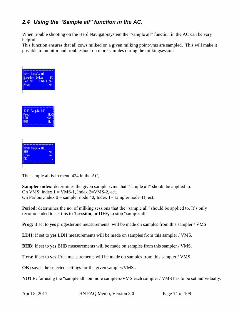
The sample all is in menu 424 in the AC,
Sampler index: determines the given sampler/vms that “sample all” should be applied to.
On VMS: index 1 = VMS-1, Index 2=VMS-2, ect.
On Parlour:index 0 = sampler node 40, Index 1= sampler node 41, ect.
Period: determines the no. of milking sessions that the “sample all” should be applied to. It‟s only
recommended to set this to 1 session, or OFF, to stop “sample all”
Prog: if set to yes progesterone measurements will be made on samples from this sampler / VMS.
LDH: if set to yes LDH measurements will be made on samples from this sampler / VMS.
BHB: if set to yes BHB measurements will be made on samples from this sampler / VMS.
Urea: if set to yes Urea measurements will be made on samples from this sampler / VMS.
OK: saves the selected settings for the given sampler/VMS..
NOTE: for using the “sample all” on more samplers/VMS each sampler / VMS has to be set individually.
April 8, 2011 HN FAQ Memo, Version 3.0 Page 15 of 108
3 Best Practices / How do I.
3.1 Sample Intake
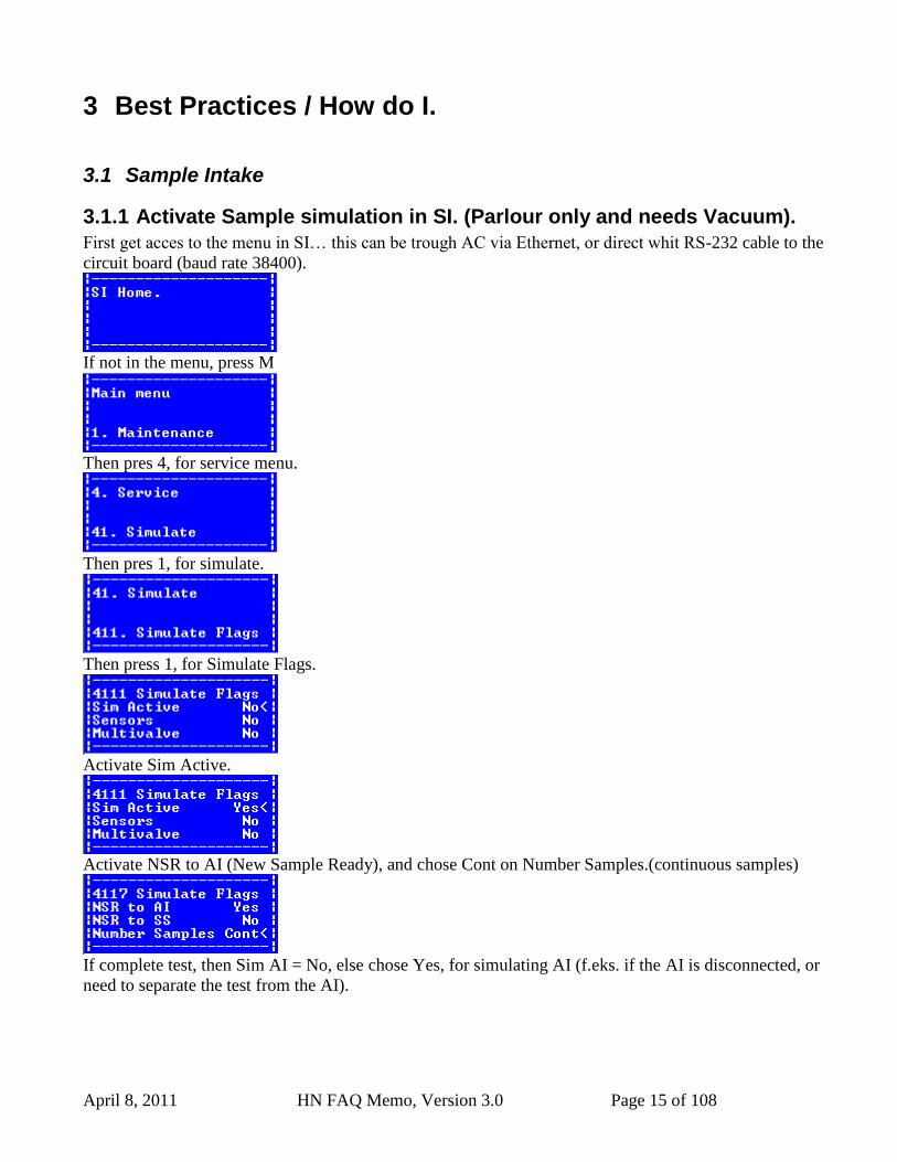
3.1.1 Activate Sample simulation in SI. (Parlour only and needs Vacuum).
First get acces to the menu in SI… this can be trough AC via Ethernet, or direct whit RS-232 cable to the
circuit board (baud rate 38400).
If not in the menu, press M
Then pres 4, for service menu.
Then pres 1, for simulate.
Then press 1, for Simulate Flags.
Activate Sim Active.
Activate NSR to AI (New Sample Ready), and chose Cont on Number Samples.(continuous samples)
If complete test, then Sim AI = No, else chose Yes, for simulating AI (f.eks. if the AI is disconnected, or
need to separate the test from the AI).

April 8, 2011 HN FAQ Memo, Version 3.0 Page 16 of 108
After pressing OK, the test start, and will take samples from the first sampler on the Multivalve.
April 8, 2011 HN FAQ Memo, Version 3.0 Page 17 of 108
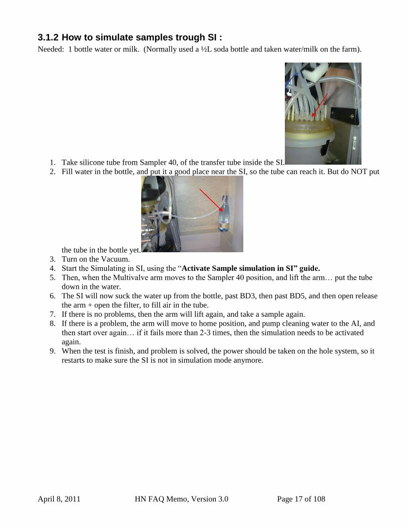
3.1.2 How to simulate samples trough SI :
Needed: 1 bottle water or milk. (Normally used a ½L soda bottle and taken water/milk on the farm).
1. Take silicone tube from Sampler 40, of the transfer tube inside the SI.
2. Fill water in the bottle, and put it a good place near the SI, so the tube can reach it. But do NOT put
the tube in the bottle yet.
3. Turn on the Vacuum.
4. Start the Simulating in SI, using the “Activate Sample simulation in SI” guide.
5. Then, when the Multivalve arm moves to the Sampler 40 position, and lift the arm… put the tube
down in the water.
6. The SI will now suck the water up from the bottle, past BD3, then past BD5, and then open release
the arm + open the filter, to fill air in the tube.
7. If there is no problems, then the arm will lift again, and take a sample again.
8. If there is a problem, the arm will move to home position, and pump cleaning water to the AI, and
then start over again… if it fails more than 2-3 times, then the simulation needs to be activated
again.
9. When the test is finish, and problem is solved, the power should be taken on the hole system, so it
restarts to make sure the SI is not in simulation mode anymore.
April 8, 2011 HN FAQ Memo, Version 3.0 Page 18 of 108
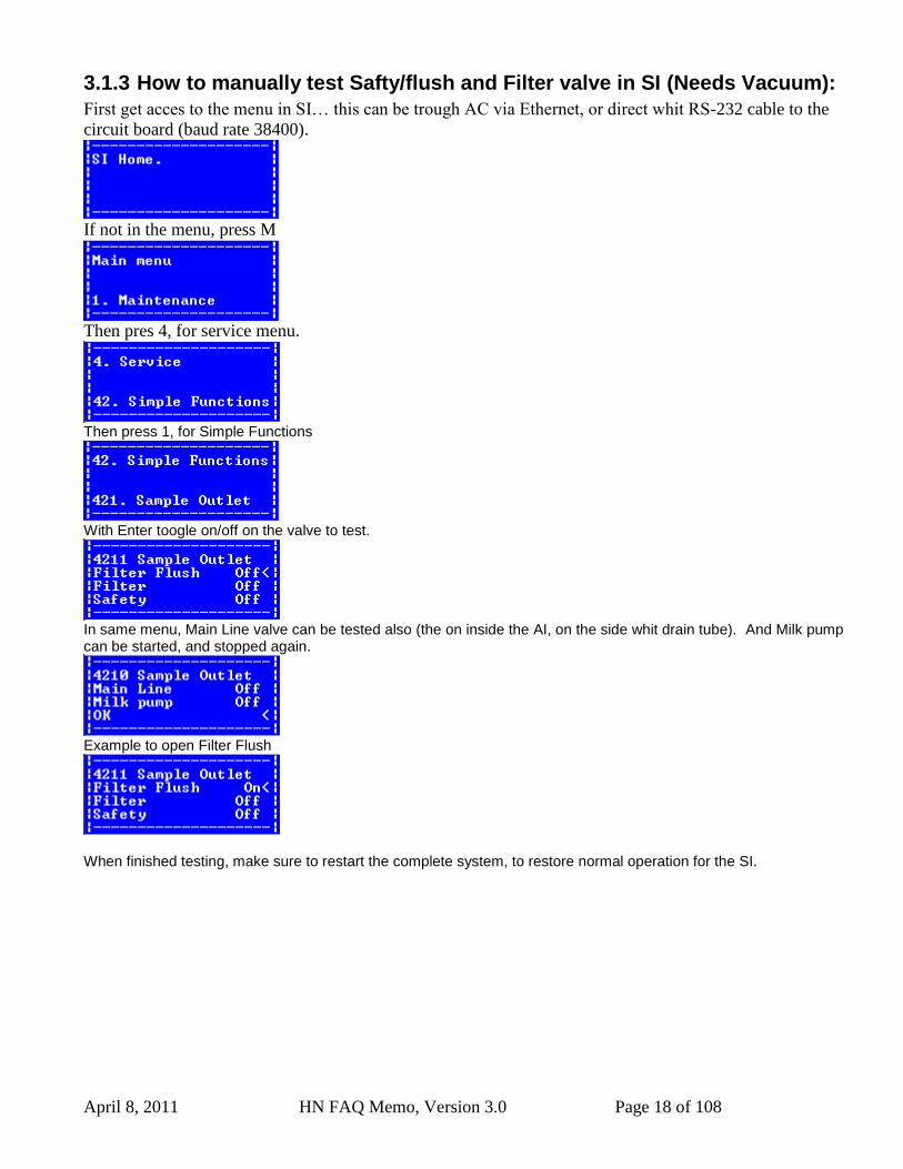
3.1.3 How to manually test Safty/flush and Filter valve in SI (Needs Vacuum):
First get acces to the menu in SI… this can be trough AC via Ethernet, or direct whit RS-232 cable to the
circuit board (baud rate 38400).
If not in the menu, press M
Then pres 4, for service menu.
Then press 1, for Simple Functions
With Enter toogle on/off on the valve to test.
In same menu, Main Line valve can be tested also (the on inside the AI, on the side whit drain tube). And Milk pump can be started, and stopped again.
Example to open Filter Flush
When finished testing, make sure to restart the complete system, to restore normal operation for the SI.
April 8, 2011 HN FAQ Memo, Version 3.0 Page 19 of 108
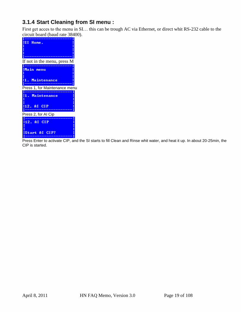
3.1.4 Start Cleaning from SI menu :
First get acces to the menu in SI… this can be trough AC via Ethernet, or direct whit RS-232 cable to the
circuit board (baud rate 38400).
If not in the menu, press M
Press 1, for Maintenance menu
Press 2, for AI Cip
Press Enter to activate CIP, and the SI starts to fill Clean and Rinse whit water, and heat it up. In about 20-25min, the CIP is started.
April 8, 2011 HN FAQ Memo, Version 3.0 Page 20 of 108
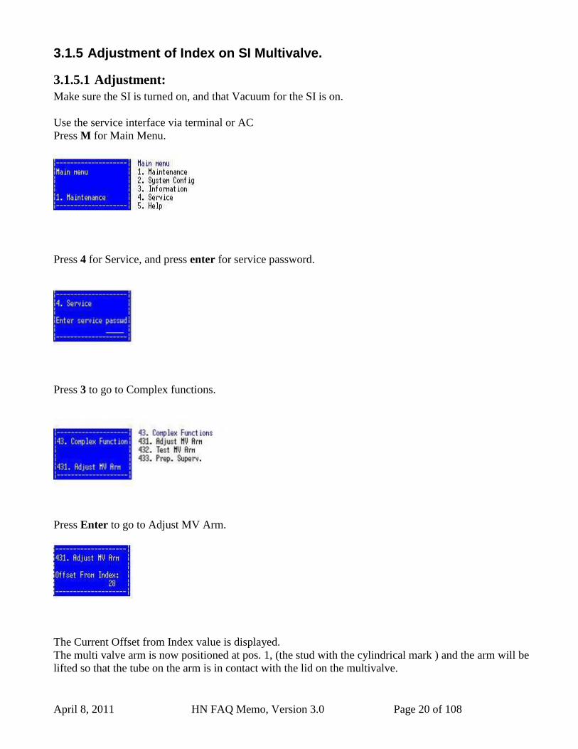
3.1.5 Adjustment of Index on SI Multivalve.
3.1.5.1 Adjustment:
Make sure the SI is turned on, and that Vacuum for the SI is on.
Use the service interface via terminal or AC
Press M for Main Menu.
Press 4 for Service, and press enter for service password.
Press 3 to go to Complex functions.
Press Enter to go to Adjust MV Arm.
The Current Offset from Index value is displayed.
The multi valve arm is now positioned at pos. 1, (the stud with the cylindrical mark ) and the arm will be
lifted so that the tube on the arm is in contact with the lid on the multivalve.
April 8, 2011 HN FAQ Memo, Version 3.0 Page 21 of 108
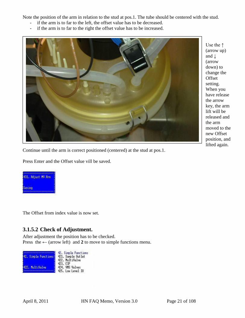
Note the position of the arm in relation to the stud at pos.1. The tube should be centered with the stud.
- if the arm is to far to the left, the offset value has to be decreased.
- if the arm is to far to the right the offset value has to be increased.
Use the ↑
(arrow up)
and ↓
(arrow
down) to
change the
Offset
setting.
When you
have release
the arrow
key, the arm
lift will be
released and
the arm
moved to the
new Offset
position, and
lifted again.
Continue until the arm is correct positioned (centered) at the stud at pos.1.
Press Enter and the Offset value vill be saved.
The Offset from index value is now set.
3.1.5.2 Check of Adjustment.
After adjustment the position has to be checked.
Press the ← (arrow left) and 2 to move to simple functions menu.
Stud 1, and tube on
MV arm has to be
centered.
April 8, 2011 HN FAQ Memo, Version 3.0 Page 22 of 108
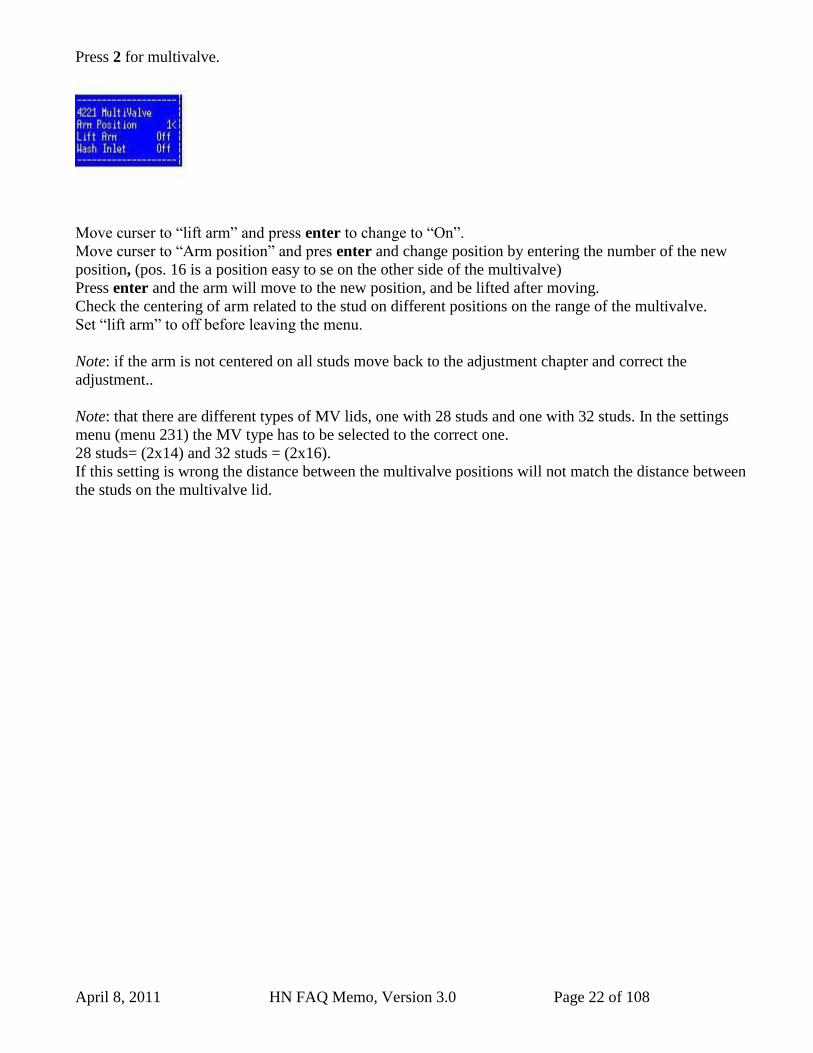
Press 2 for multivalve.
Move curser to “lift arm” and press enter to change to “On”.
Move curser to “Arm position” and pres enter and change position by entering the number of the new
position, (pos. 16 is a position easy to se on the other side of the multivalve)
Press enter and the arm will move to the new position, and be lifted after moving.
Check the centering of arm related to the stud on different positions on the range of the multivalve.
Set “lift arm” to off before leaving the menu.
Note: if the arm is not centered on all studs move back to the adjustment chapter and correct the
adjustment..
Note: that there are different types of MV lids, one with 28 studs and one with 32 studs. In the settings
menu (menu 231) the MV type has to be selected to the correct one.
28 studs= (2x14) and 32 studs = (2x16).
If this setting is wrong the distance between the multivalve positions will not match the distance between
the studs on the multivalve lid.
April 8, 2011 HN FAQ Memo, Version 3.0 Page 23 of 108
3.1.6 Mounting the Tube for Milkpump in the Sample Intake.
Article no. 5356080241 Lattec p/n : 60026782
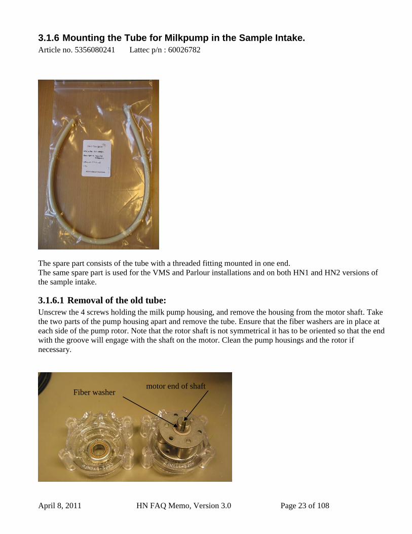
The spare part consists of the tube with a threaded fitting mounted in one end.
The same spare part is used for the VMS and Parlour installations and on both HN1 and HN2 versions of
the sample intake.
3.1.6.1 Removal of the old tube:
Unscrew the 4 screws holding the milk pump housing, and remove the housing from the motor shaft. Take
the two parts of the pump housing apart and remove the tube. Ensure that the fiber washers are in place at
each side of the pump rotor. Note that the rotor shaft is not symmetrical it has to be oriented so that the end
with the groove will engage with the shaft on the motor. Clean the pump housings and the rotor if
necessary.
Fiber washer motor end of shaft
April 8, 2011 HN FAQ Memo, Version 3.0 Page 24 of 108
3.1.6.2 Mounting of the new tube.
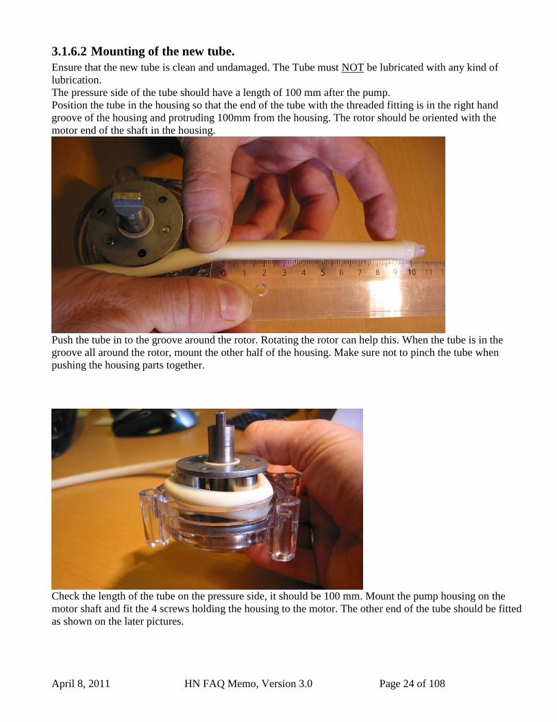
Ensure that the new tube is clean and undamaged. The Tube must NOT be lubricated with any kind of
lubrication.
The pressure side of the tube should have a length of 100 mm after the pump.
Position the tube in the housing so that the end of the tube with the threaded fitting is in the right hand
groove of the housing and protruding 100mm from the housing. The rotor should be oriented with the
motor end of the shaft in the housing.
Push the tube in to the groove around the rotor. Rotating the rotor can help this. When the tube is in the
groove all around the rotor, mount the other half of the housing. Make sure not to pinch the tube when
pushing the housing parts together.
Check the length of the tube on the pressure side, it should be 100 mm. Mount the pump housing on the
motor shaft and fit the 4 screws holding the housing to the motor. The other end of the tube should be fitted
as shown on the later pictures.
April 8, 2011 HN FAQ Memo, Version 3.0 Page 25 of 108
100 mm
Tighten strip
around tube
at filter stud.
100 mm
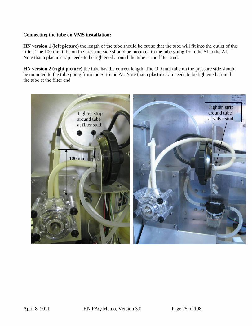
Connecting the tube on VMS installation:
HN version 1 (left picture) the length of the tube should be cut so that the tube will fit into the outlet of the
filter. The 100 mm tube on the pressure side should be mounted to the tube going from the SI to the AI.
Note that a plastic strap needs to be tightened around the tube at the filter stud.
HN version 2 (right picture) the tube has the correct length. The 100 mm tube on the pressure side should
be mounted to the tube going from the SI to the AI. Note that a plastic strap needs to be tightened around
the tube at the filter end.
Tighten strip
around tube
at valve stud.
April 8, 2011 HN FAQ Memo, Version 3.0 Page 26 of 108
100 mm 100 mm
Tighten strip
around tube
At valve stud.
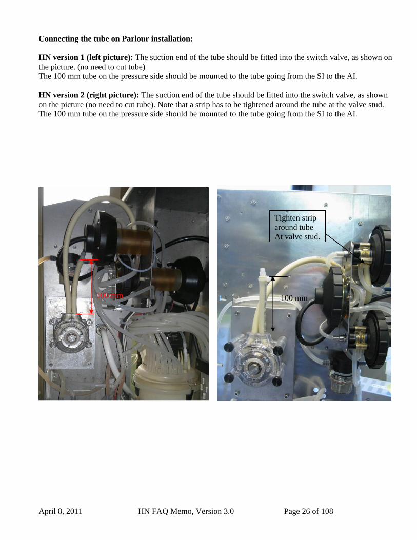
Connecting the tube on Parlour installation:
HN version 1 (left picture): The suction end of the tube should be fitted into the switch valve, as shown on
the picture. (no need to cut tube)
The 100 mm tube on the pressure side should be mounted to the tube going from the SI to the AI.
HN version 2 (right picture): The suction end of the tube should be fitted into the switch valve, as shown
on the picture (no need to cut tube). Note that a strip has to be tightened around the tube at the valve stud.
The 100 mm tube on the pressure side should be mounted to the tube going from the SI to the AI.
April 8, 2011 HN FAQ Memo, Version 3.0 Page 27 of 108
3.1.7 Correct mounting of the Air detector assembly, BD1,BD5,BD3 and BD4.
3.1.7.1 Important information: Keeping the BD dry.
The sensors may never be left wet or with drops of fluid on as this can cause system
failures. If the inside of SI unit has to be cleaned it can be hard to avoid the sensors getting wet. If the sensors get
wet they have to be thoroughly dried.
BD3 and/or BD4 should be dismounted from the tube and dried with compressed air and a dry cloth.
Assemble as described in appendix 2
BD1 and BD5 should not be dismounted from the tube but carefully dried with compressed air and a dry
cloth. Take great care to blow away all fluid that is on the sensor beneath the tube.
April 8, 2011 HN FAQ Memo, Version 3.0 Page 28 of 108
3.1.7.2 BD1 installation
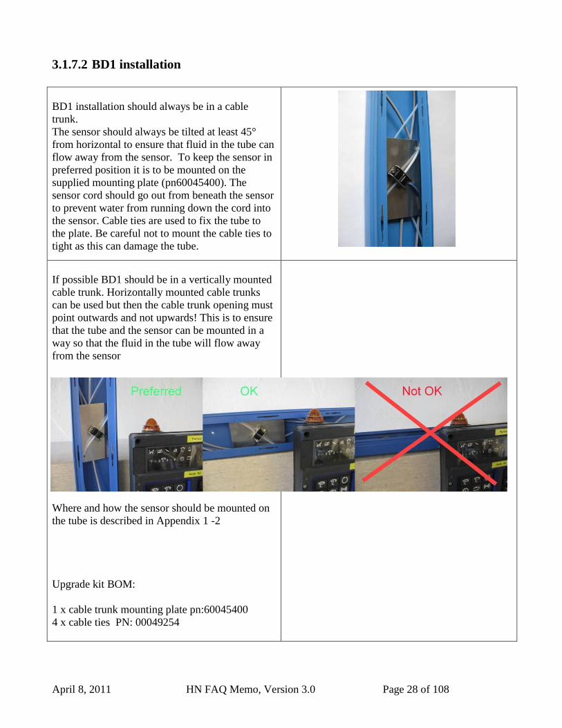
BD1 installation should always be in a cable
trunk.
The sensor should always be tilted at least 45°
from horizontal to ensure that fluid in the tube can
flow away from the sensor. To keep the sensor in
preferred position it is to be mounted on the
supplied mounting plate (pn60045400). The
sensor cord should go out from beneath the sensor
to prevent water from running down the cord into
the sensor. Cable ties are used to fix the tube to
the plate. Be careful not to mount the cable ties to
tight as this can damage the tube.
If possible BD1 should be in a vertically mounted
cable trunk. Horizontally mounted cable trunks
can be used but then the cable trunk opening must
point outwards and not upwards! This is to ensure
that the tube and the sensor can be mounted in a
way so that the fluid in the tube will flow away
from the sensor
Where and how the sensor should be mounted on
the tube is described in Appendix 1 -2
Upgrade kit BOM:
1 x cable trunk mounting plate pn:60045400
4 x cable ties PN: 00049254
April 8, 2011 HN FAQ Memo, Version 3.0 Page 29 of 108
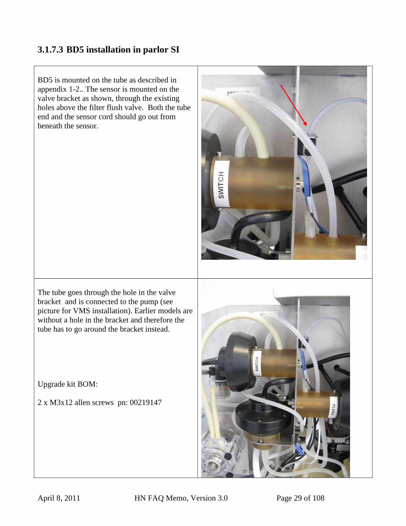
3.1.7.3 BD5 installation in parlor SI
BD5 is mounted on the tube as described in
appendix 1-2.. The sensor is mounted on the
valve bracket as shown, through the existing
holes above the filter flush valve. Both the tube
end and the sensor cord should go out from
beneath the sensor.
The tube goes through the hole in the valve
bracket and is connected to the pump (see
picture for VMS installation). Earlier models are
without a hole in the bracket and therefore the
tube has to go around the bracket instead.
Upgrade kit BOM:
2 x M3x12 allen screws pn: 00219147
April 8, 2011 HN FAQ Memo, Version 3.0 Page 30 of 108
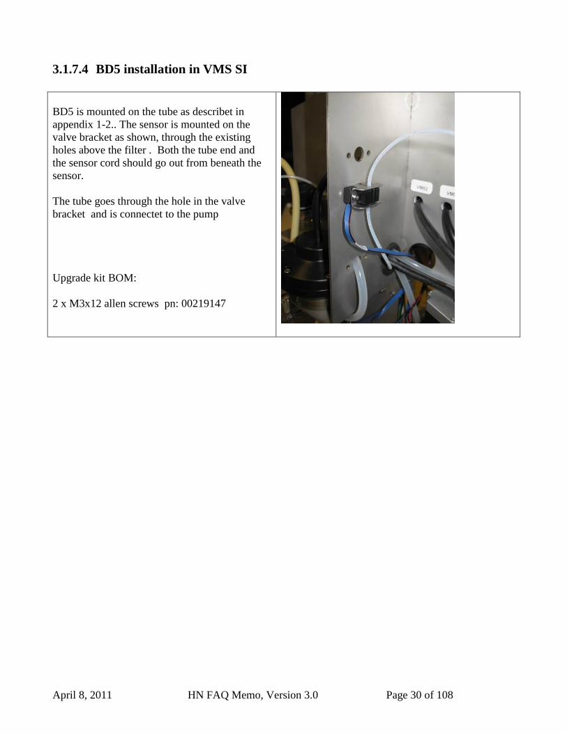
3.1.7.4 BD5 installation in VMS SI
BD5 is mounted on the tube as describet in
appendix 1-2.. The sensor is mounted on the
valve bracket as shown, through the existing
holes above the filter . Both the tube end and
the sensor cord should go out from beneath the
sensor.
The tube goes through the hole in the valve
bracket and is connectet to the pump
Upgrade kit BOM:
2 x M3x12 allen screws pn: 00219147
April 8, 2011 HN FAQ Memo, Version 3.0 Page 31 of 108
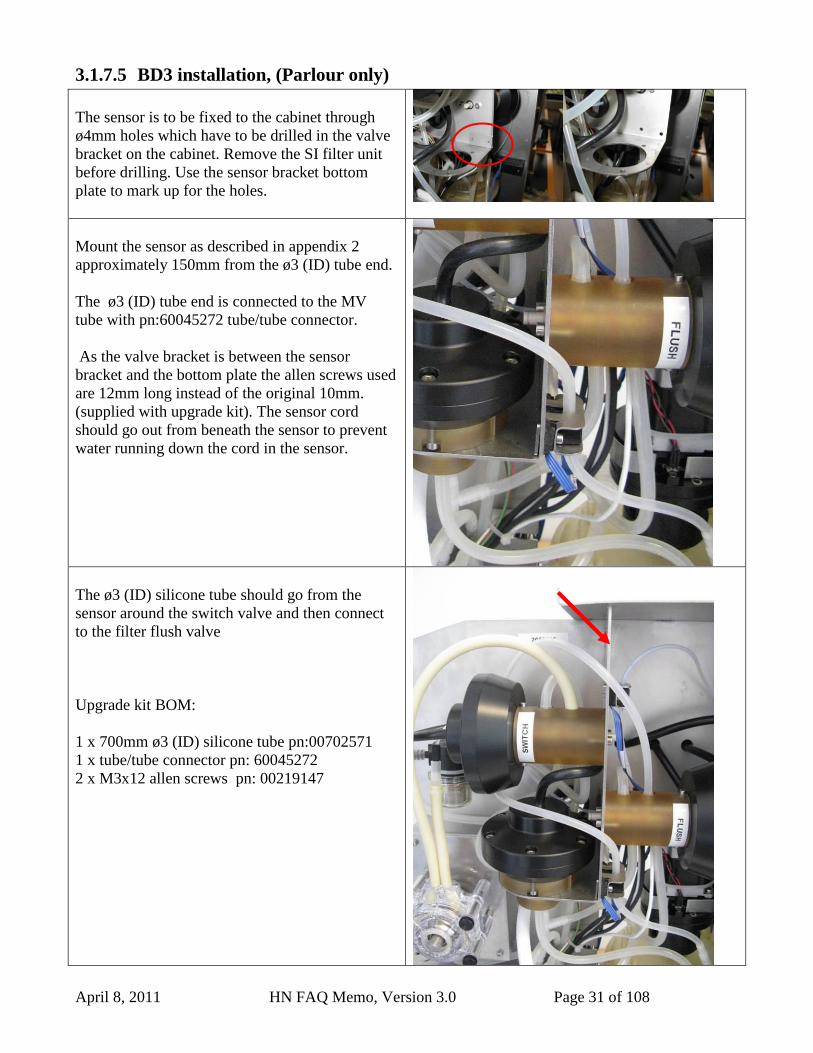
3.1.7.5 BD3 installation, (Parlour only)
The sensor is to be fixed to the cabinet through
ø4mm holes which have to be drilled in the valve
bracket on the cabinet. Remove the SI filter unit
before drilling. Use the sensor bracket bottom
plate to mark up for the holes.
Mount the sensor as described in appendix 2
approximately 150mm from the ø3 (ID) tube end.
The ø3 (ID) tube end is connected to the MV
tube with pn:60045272 tube/tube connector.
As the valve bracket is between the sensor
bracket and the bottom plate the allen screws used
are 12mm long instead of the original 10mm.
(supplied with upgrade kit). The sensor cord
should go out from beneath the sensor to prevent
water running down the cord in the sensor.
The ø3 (ID) silicone tube should go from the
sensor around the switch valve and then connect
to the filter flush valve
Upgrade kit BOM:
1 x 700mm ø3 (ID) silicone tube pn:00702571
1 x tube/tube connector pn: 60045272
2 x M3x12 allen screws pn: 00219147
April 8, 2011 HN FAQ Memo, Version 3.0 Page 32 of 108
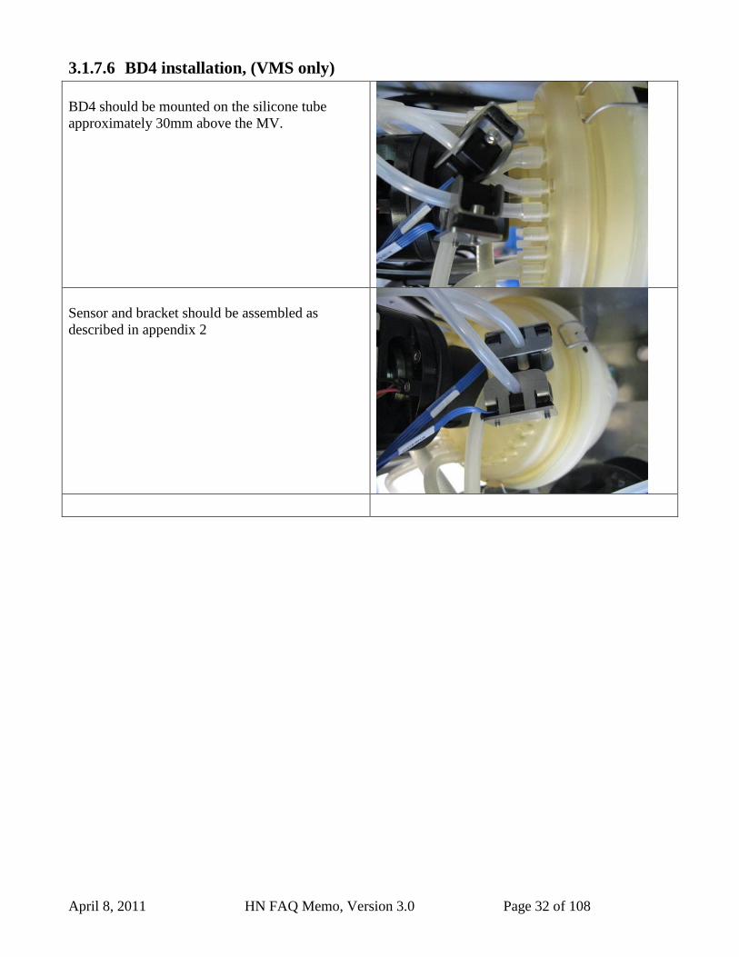
3.1.7.6 BD4 installation, (VMS only)
BD4 should be mounted on the silicone tube
approximately 30mm above the MV.
Sensor and bracket should be assembled as
described in appendix 2
April 8, 2011 HN FAQ Memo, Version 3.0 Page 33 of 108
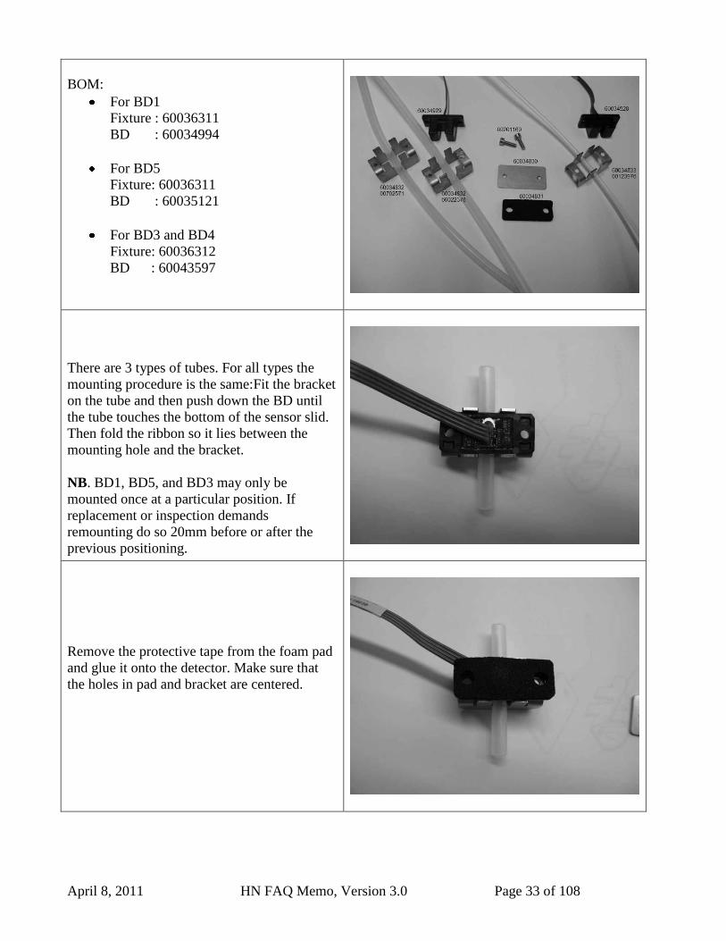
BOM:
For BD1
Fixture : 60036311
BD : 60034994
For BD5
Fixture: 60036311
BD : 60035121
For BD3 and BD4
Fixture: 60036312
BD : 60043597
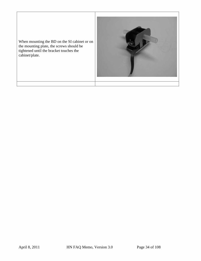
There are 3 types of tubes. For all types the
mounting procedure is the same:Fit the bracket
on the tube and then push down the BD until
the tube touches the bottom of the sensor slid.
Then fold the ribbon so it lies between the
mounting hole and the bracket.
NB. BD1, BD5, and BD3 may only be
mounted once at a particular position. If
replacement or inspection demands
remounting do so 20mm before or after the
previous positioning.
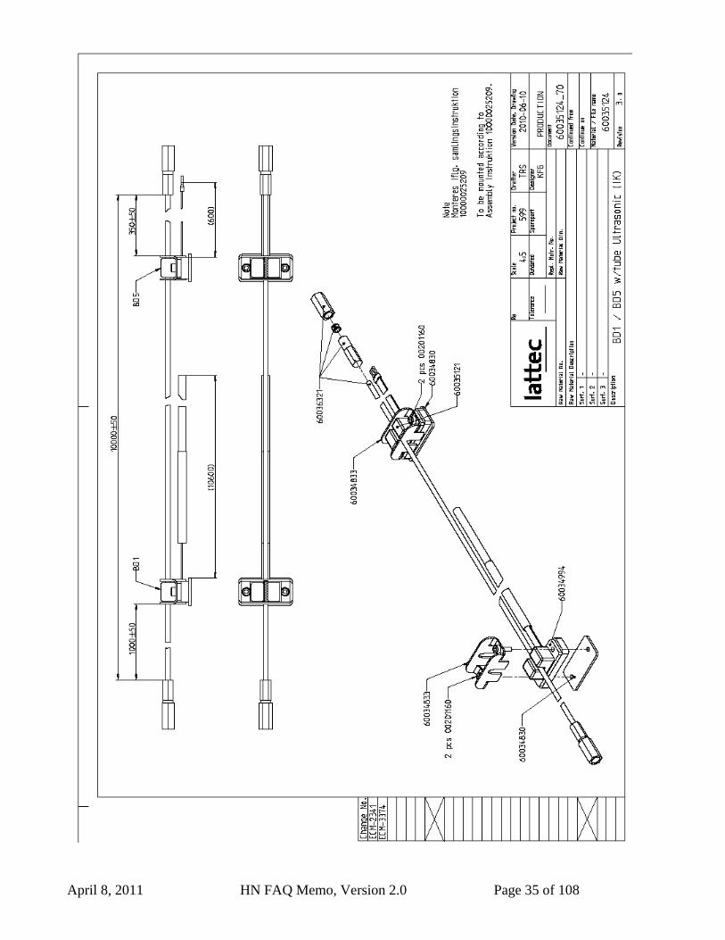
Remove the protective tape from the foam pad
and glue it onto the detector. Make sure that
the holes in pad and bracket are centered.
April 8, 2011 HN FAQ Memo, Version 3.0 Page 34 of 108
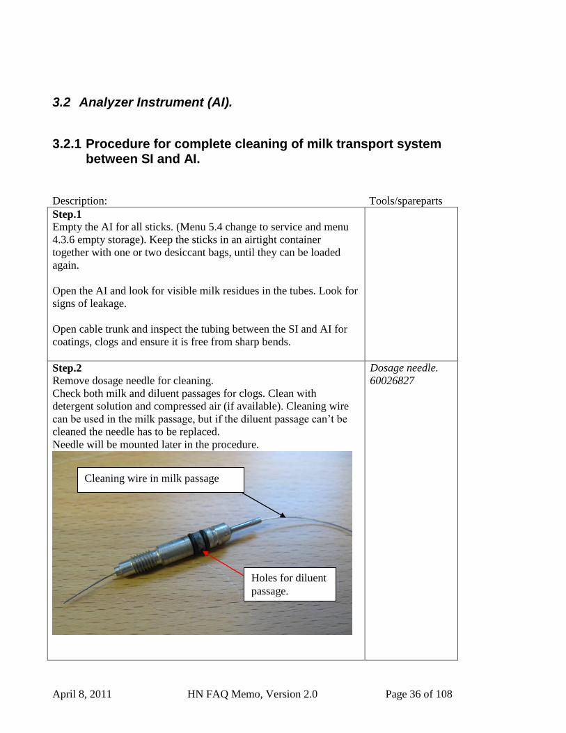
When mounting the BD on the SI cabinet or on
the mounting plate, the screws should be
tightened until the bracket touches the
cabinet/plate.
April 8, 2011 HN FAQ Memo, Version 2.0 Page 35 of 108
April 8, 2011 HN FAQ Memo, Version 2.0 Page 36 of 108
3.2 Analyzer Instrument (AI).
3.2.1 Procedure for complete cleaning of milk transport system between SI and AI.
Description: Tools/spareparts
Step.1
Empty the AI for all sticks. (Menu 5.4 change to service and menu
4.3.6 empty storage). Keep the sticks in an airtight container
together with one or two desiccant bags, until they can be loaded
again.
Open the AI and look for visible milk residues in the tubes. Look for
signs of leakage.
Open cable trunk and inspect the tubing between the SI and AI for
coatings, clogs and ensure it is free from sharp bends.
Step.2
Remove dosage needle for cleaning.
Check both milk and diluent passages for clogs. Clean with
detergent solution and compressed air (if available). Cleaning wire
can be used in the milk passage, but if the diluent passage can‟t be
cleaned the needle has to be replaced.
Needle will be mounted later in the procedure.
Dosage needle.
60026827
Cleaning wire in milk passage
Holes for diluent
passage.
April 8, 2011 HN FAQ Memo, Version 2.0 Page 37 of 108
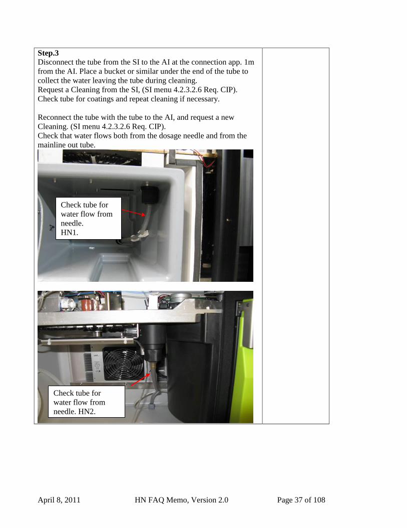
Step.3
Disconnect the tube from the SI to the AI at the connection app. 1m
from the AI. Place a bucket or similar under the end of the tube to
collect the water leaving the tube during cleaning.
Request a Cleaning from the SI, (SI menu 4.2.3.2.6 Req. CIP).
Check tube for coatings and repeat cleaning if necessary.
Reconnect the tube with the tube to the AI, and request a new
Cleaning. (SI menu 4.2.3.2.6 Req. CIP).
Check that water flows both from the dosage needle and from the
mainline out tube.
Check tube for
water flow from
needle.
HN1.
Check tube for
water flow from
needle. HN2.
April 8, 2011 HN FAQ Memo, Version 2.0 Page 38 of 108
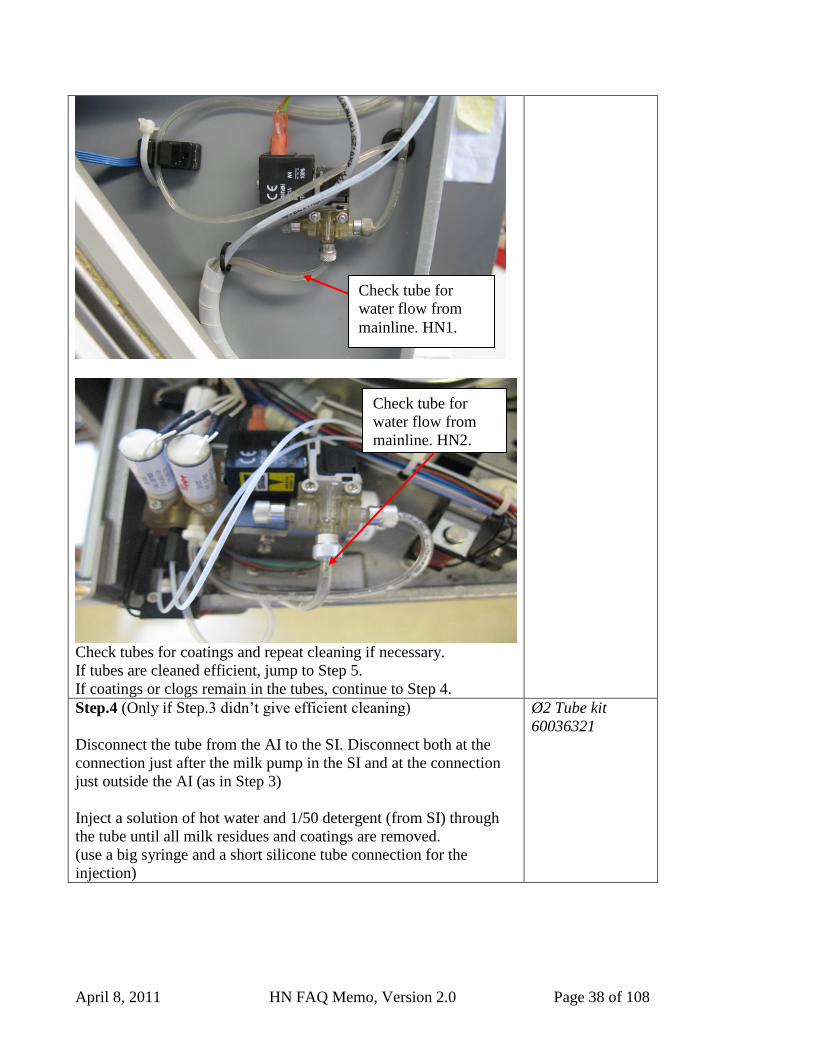
Check tubes for coatings and repeat cleaning if necessary.
If tubes are cleaned efficient, jump to Step 5.
If coatings or clogs remain in the tubes, continue to Step 4.
Step.4 (Only if Step.3 didn‟t give efficient cleaning)
Disconnect the tube from the AI to the SI. Disconnect both at the
connection just after the milk pump in the SI and at the connection
just outside the AI (as in Step 3)
Inject a solution of hot water and 1/50 detergent (from SI) through
the tube until all milk residues and coatings are removed.
(use a big syringe and a short silicone tube connection for the
injection)
Ø2 Tube kit
60036321
Check tube for
water flow from
mainline. HN1.
Check tube for
water flow from
mainline. HN2.
April 8, 2011 HN FAQ Memo, Version 2.0 Page 39 of 108
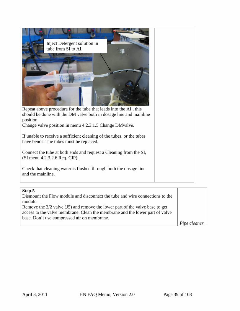
Repeat above procedure for the tube that leads into the AI , this
should be done with the DM valve both in dosage line and mainline
position.
Change valve position in menu 4.2.3.1.5 Change DMvalve.
If unable to receive a sufficient cleaning of the tubes, or the tubes
have bends. The tubes must be replaced.
Connect the tube at both ends and request a Cleaning from the SI,
(SI menu 4.2.3.2.6 Req. CIP).
Check that cleaning water is flushed through both the dosage line
and the mainline.
Step.5
Dismount the Flow module and disconnect the tube and wire connections to the
module.
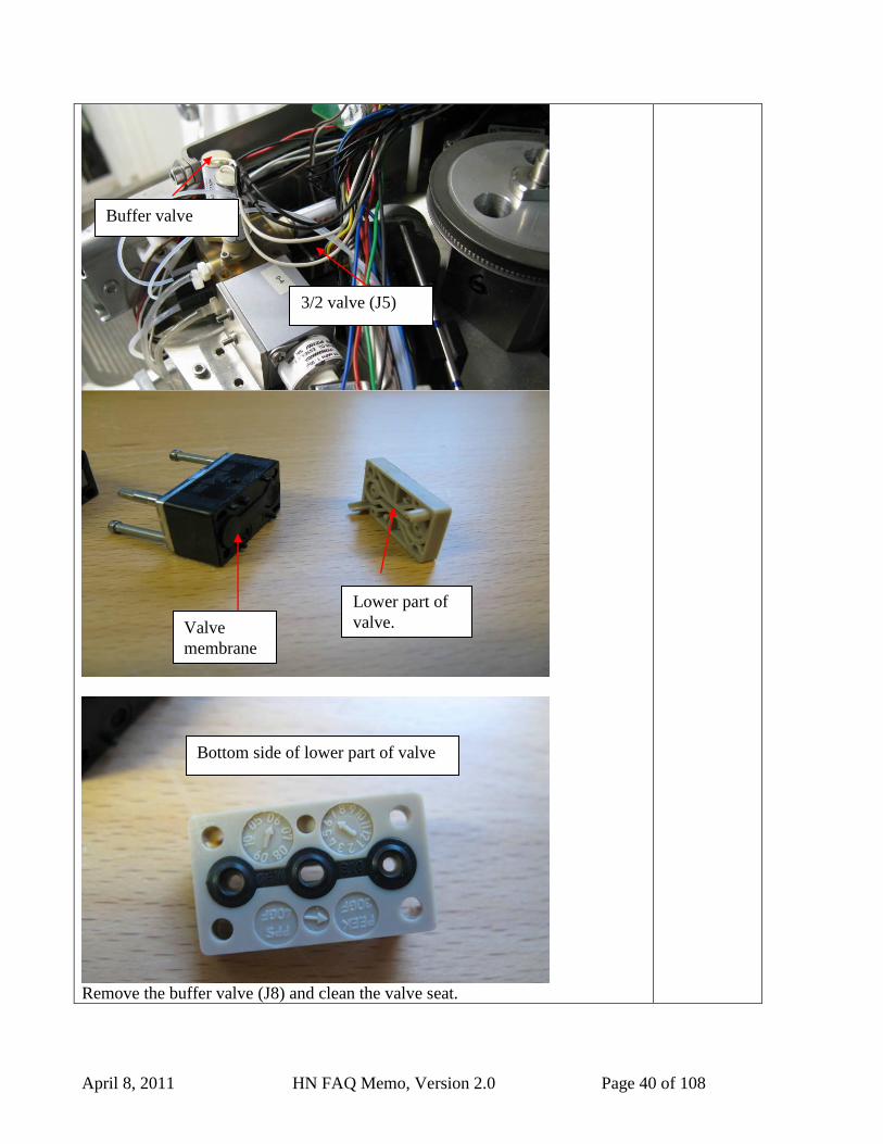
Remove the 3/2 valve (J5) and remove the lower part of the valve base to get
access to the valve membrane. Clean the membrane and the lower part of valve
base. Don‟t use compressed air on membrane.
Pipe cleaner
Inject Detergent solution in
tube from SI to AI.
April 8, 2011 HN FAQ Memo, Version 2.0 Page 40 of 108
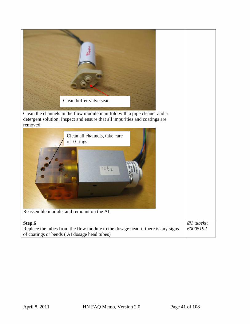
Remove the buffer valve (J8) and clean the valve seat.
Valve
membrane
Lower part of
valve.
Bottom side of lower part of valve
3/2 valve (J5)
Buffer valve
April 8, 2011 HN FAQ Memo, Version 2.0 Page 41 of 108
Clean the channels in the flow module manifold with a pipe cleaner and a
detergent solution. Inspect and ensure that all impurities and coatings are
removed.
Reassemble module, and remount on the AI.
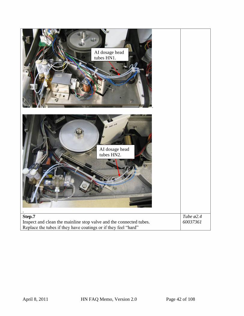
Step.6 Replace the tubes from the flow module to the dosage head if there is any signs
of coatings or bends ( AI dosage head tubes)
Ø1 tubekit
60005192
Clean buffer valve seat.
Clean all channels, take care
of 0-rings.
April 8, 2011 HN FAQ Memo, Version 2.0 Page 42 of 108
.
.
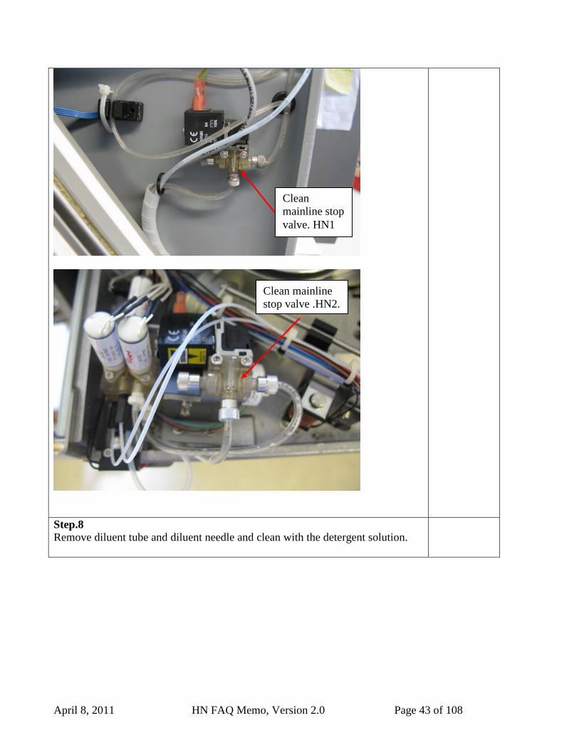
Step.7 Inspect and clean the mainline stop valve and the connected tubes.
Replace the tubes if they have coatings or if they feel “hard”
Tube ø2.4
60037361
AI dosage head
tubes HN1.
AI dosage head
tubes HN2.
April 8, 2011 HN FAQ Memo, Version 2.0 Page 43 of 108
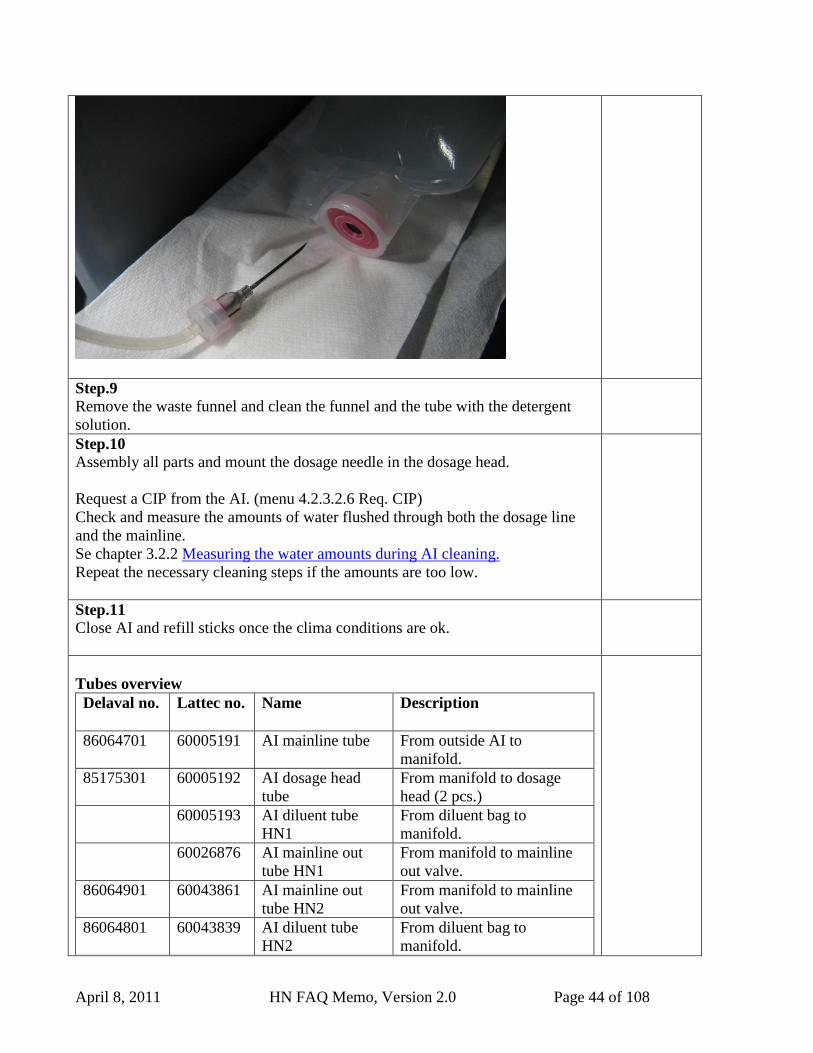
Step.8
Remove diluent tube and diluent needle and clean with the detergent solution.
Clean
mainline stop
valve. HN1
Clean mainline
stop valve .HN2.
April 8, 2011 HN FAQ Memo, Version 2.0 Page 44 of 108
Step.9
Remove the waste funnel and clean the funnel and the tube with the detergent
solution.
Step.10
Assembly all parts and mount the dosage needle in the dosage head.
Request a CIP from the AI. (menu 4.2.3.2.6 Req. CIP)
Check and measure the amounts of water flushed through both the dosage line
and the mainline.
Se chapter 3.2.2 Measuring the water amounts during AI cleaning.
Repeat the necessary cleaning steps if the amounts are too low.
Step.11
Close AI and refill sticks once the clima conditions are ok.
Tubes overview
Delaval no. Lattec no. Name Description
86064701 60005191 AI mainline tube From outside AI to
manifold.
85175301 60005192 AI dosage head
tube
From manifold to dosage
head (2 pcs.)
60005193 AI diluent tube
HN1
From diluent bag to
manifold.
60026876 AI mainline out
tube HN1
From manifold to mainline
out valve.
86064901
60043861 AI mainline out
tube HN2
From manifold to mainline
out valve.
86064801 60043839 AI diluent tube
HN2
From diluent bag to
manifold.
April 8, 2011 HN FAQ Memo, Version 2.0 Page 45 of 108
3.2.2 Measuring the water amounts during AI cleaning.
During a CIP of the AI, water is flushed through both the main line and the dosage line. The
amount of water indicates if there is clogging or sharp bends on the tubes. It is therefore a useful
“tool” for trouble shooting, when fixing quarantine and dosage problems.
The measuring can be done both before, and after cleaning the system as described in chapter:
3.2.1Procedure for complete cleaning of milk transport system between SI and AI.
Tools needed:
2 suitable containers, to collect Water from the AI. 0,5 liter or bigger.
A measuring cup with scale intervals in min 20 ml.
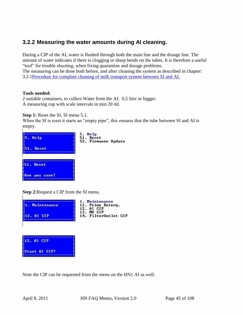
Step 1: Reset the SI, SI menu 5.1.
When the SI is reset it starts an “empty pipe”, this ensures that the tube between SI and AI is
empty.
Step 2:Request a CIP from the SI menu.
Note the CIP can be requested from the menu on the HN1 AI as well.
April 8, 2011 HN FAQ Memo, Version 2.0 Page 46 of 108
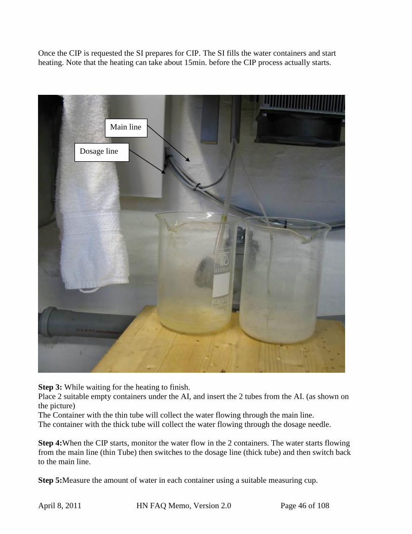
Once the CIP is requested the SI prepares for CIP. The SI fills the water containers and start
heating. Note that the heating can take about 15min. before the CIP process actually starts.
Step 3: While waiting for the heating to finish.
Place 2 suitable empty containers under the AI, and insert the 2 tubes from the AI. (as shown on
the picture)
The Container with the thin tube will collect the water flowing through the main line.
The container with the thick tube will collect the water flowing through the dosage needle.
Step 4:When the CIP starts, monitor the water flow in the 2 containers. The water starts flowing
from the main line (thin Tube) then switches to the dosage line (thick tube) and then switch back
to the main line.
Step 5:Measure the amount of water in each container using a suitable measuring cup.
Dosage line
Main line
April 8, 2011 HN FAQ Memo, Version 2.0 Page 47 of 108
The amount should not deviate far from these nominal values.
Parlour : Main Line : app. 315ml Dosage Line: 370 ml.
VMS: Main Line : app. 315ml Dosage Line: 370 ml.
Step 6:
If the water amount is to low, look for clogging, bended tubes or leaks in the system.
If both amounts are to low: look in SI, tube from SI to AI, and Manifold.
If Main line is ok, and Dosage is low, look in needle or tubes from manifold to needle.
If Dosage line is ok, and main line is low. Look in mainline stop valve, tubes connected to this
valve or in the manifold.
Refer to Chapter 3.2.1Procedure for complete cleaning of milk transport system between SI and
AI.
April 8, 2011 HN FAQ Memo, Version 2.0 Page 48 of 108
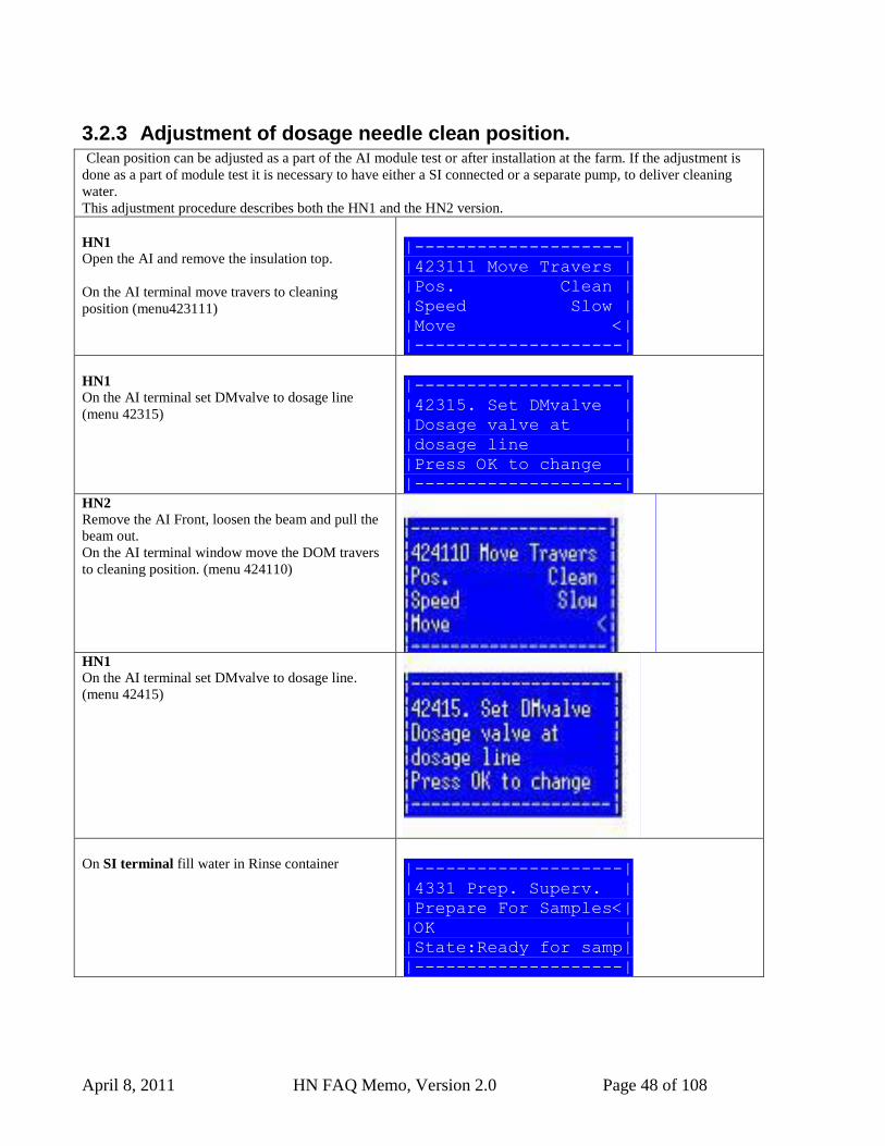
3.2.3 Adjustment of dosage needle clean position. Clean position can be adjusted as a part of the AI module test or after installation at the farm. If the adjustment is
done as a part of module test it is necessary to have either a SI connected or a separate pump, to deliver cleaning
water.
This adjustment procedure describes both the HN1 and the HN2 version.
HN1
Open the AI and remove the insulation top.
On the AI terminal move travers to cleaning
position (menu423111)
|--------------------| |423111 Move Travers |
|Pos. Clean |
|Speed Slow |
|Move <|
|--------------------|
HN1
On the AI terminal set DMvalve to dosage line
(menu 42315)
|--------------------|
|42315. Set DMvalve |
|Dosage valve at |
|dosage line |
|Press OK to change |
|--------------------| HN2
Remove the AI Front, loosen the beam and pull the
beam out.
On the AI terminal window move the DOM travers
to cleaning position. (menu 424110)
HN1
On the AI terminal set DMvalve to dosage line.
(menu 42415)
On SI terminal fill water in Rinse container |--------------------|
|4331 Prep. Superv. |
|Prepare For Samples<|
|OK |
|State:Ready for samp|
|--------------------|
April 8, 2011 HN FAQ Memo, Version 2.0 Page 49 of 108
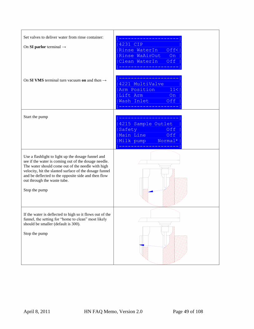
Set valves to deliver water from rinse container:
On SI parlor terminal →
On SI VMS terminal turn vacuum on and then →
|--------------------|
|4231 CIP |
|Rinse WaterIn Off<|
|Rinse WaAirOut On |
|Clean WaterIn Off |
|--------------------|
|--------------------|
|4221 MultiValve |
|Arm Position 11<|
|Lift Arm On |
|Wash Inlet Off |
|--------------------|
Start the pump |--------------------|
|4215 Sample Outlet |
|Safety Off |
|Main Line Off |
|Milk pump Normal*|
|--------------------|
Use a flashlight to light up the dosage funnel and
see if the water is coming out of the dosage needle.
The water should come out of the needle with high
velocity, hit the slanted surface of the dosage funnel
and be deflected to the opposite side and then flow
out through the waste tube.
Stop the pump
If the water is deflected to high so it flows out of the
funnel, the setting for “home to clean” most likely
should be smaller (default is 300).
Stop the pump
April 8, 2011 HN FAQ Memo, Version 2.0 Page 50 of 108
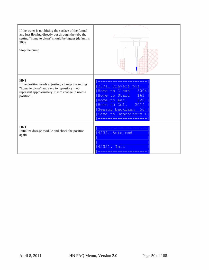
If the water is not hitting the surface of the funnel
and just flowing directly out through the tube the
setting “home to clean” should be bigger (default is
300).
Stop the pump
HN1
If the position needs adjusting, change the setting
“home to clean” and save to repository. ±40
represent approximately ±1mm change in needle
position.
|--------------------|
|23311 Travers pos. |
|Home to Clean 300<|
|Home to Start 161 |
|Home to Lat. 920 |
|Home to Col. 2014 |
|Sensor backlash 50 |
|Save to Repository <|
|--------------------|
HN1
Initialize dosage module and check the position
again
|--------------------|
|4232. Auto cmd |
| |
| |
|42321. Init |
|--------------------|
April 8, 2011 HN FAQ Memo, Version 2.0 Page 51 of 108
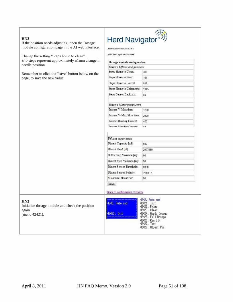
HN2
If the position needs adjusting, open the Dosage
module configuration page in the AI web interface.
Change the setting “Steps home to clean”.
±40 steps represent approximately ±1mm change in
needle position.
Remember to click the “save” button below on the
page, to save the new value.
HN2
Initialize dosage module and check the position
again
(menu 42421).
April 8, 2011 HN FAQ Memo, Version 2.0 Page 52 of 108
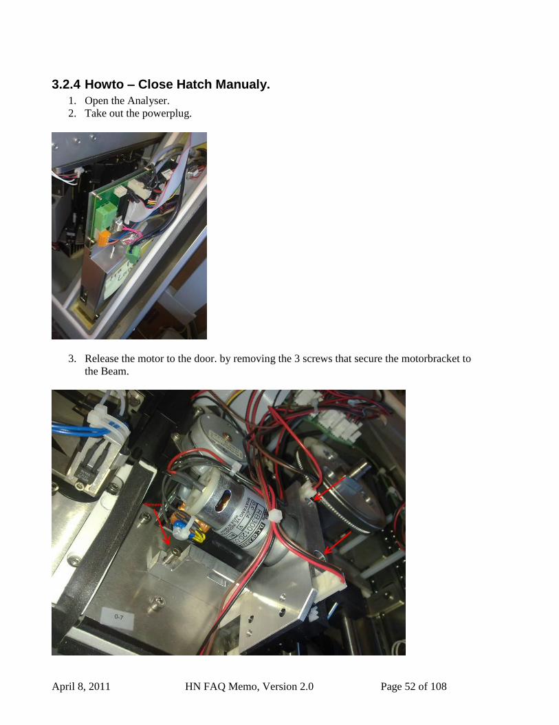
3.2.4 Howto – Close Hatch Manualy.
1. Open the Analyser.
2. Take out the powerplug.
3. Release the motor to the door. by removing the 3 screws that secure the motorbracket to
the Beam.
April 8, 2011 HN FAQ Memo, Version 2.0 Page 53 of 108
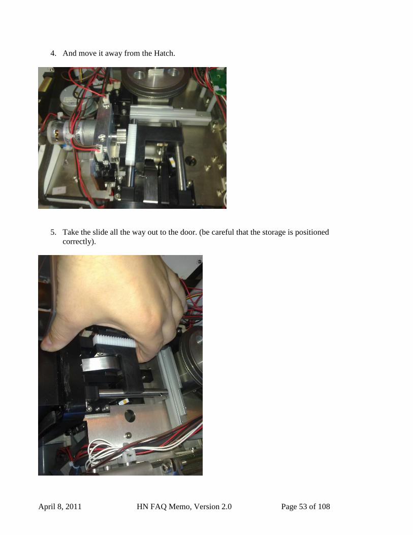
4. And move it away from the Hatch.
5. Take the slide all the way out to the door. (be careful that the storage is positioned
correctly).

April 8, 2011 HN FAQ Memo, Version 2.0 Page 54 of 108
6. And when the slide is hold out, gently close the door, so the slide goes back, and the
door stays closed. (Se the movie how it is done.)
7. When the door is closed, put the motor back on, and turn on the power to se the door
stays closed.
April 8, 2011 HN FAQ Memo, Version 2.0 Page 55 of 108
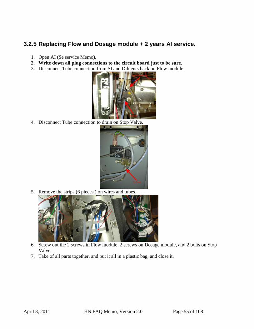
3.2.5 Replacing Flow and Dosage module + 2 years AI service.
1. Open AI (Se service Memo).
2. Write down all plug connections to the circuit board just to be sure.
3. Disconnect Tube connection from SI and Diluents back on Flow module.
4. Disconnect Tube connection to drain on Stop Valve.
5. Remove the strips (6 pieces.) on wires and tubes.
6. Screw out the 2 screws in Flow module, 2 screws on Dosage module, and 2 bolts on Stop
Valve.
7. Take of all parts together, and put it all in a plastic bag, and close it.
April 8, 2011 HN FAQ Memo, Version 2.0 Page 56 of 108
8. Mount the new parts, the dosage module has new screws, but Flow module and Stop
valve had to use the old ones.
9. Connect all the wires again.
10. Connect the two new tubes from dosage module, to flow module (part nr. 60005192)
11. Connect the tube from SI again.
12. Connect the new tube from Flow module to stop valve (part nr. 60026876)
13. Connect the new tube from Diluents bag to flow module (part nr. 60005193)
14. Connect the tube from stop valve to drain again.
15. Make sure all tubes and wires is fit correct, and then put 6 new strips on again, just to
hold, but not to tight so it damage the tubes.
16. Take new diluents, and connect it.
17. Make a Diluents prime whit the AI menu 1-Maintaince -> 2-Relpace Diluents. And
watch if there are any leaks… after a complete replace, 3-4 primes is needed to make
sure all air is out of the system again.
18. Make a cleaning whit the AI menu 1-Maintaince -> 4-Request clean , and watch when
the water comes trough, that there is no leaks.
19. If there is no leaks and all is well fitted, close the analyzer, restart the whole system whit
taking the power, and make sure the Analyser goes to standby mode.
20. Load Drybags, and when the AI is ready, load sticks and change the Drybags an extra
time.
21. Then HN is ready again.
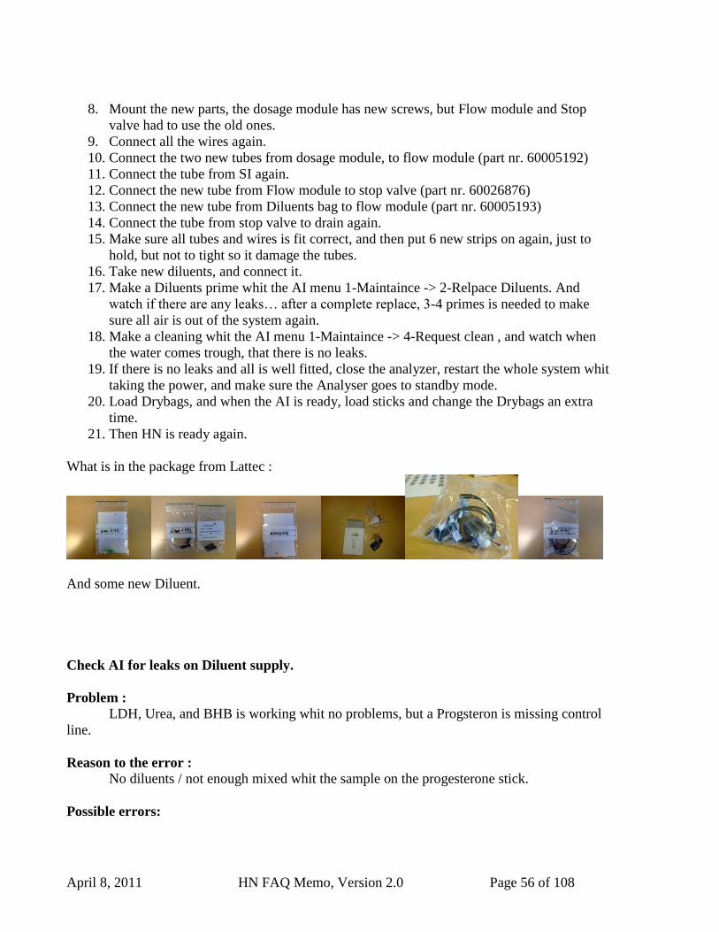
What is in the package from Lattec :
And some new Diluent.
Check AI for leaks on Diluent supply.
Problem :
LDH, Urea, and BHB is working whit no problems, but a Progsteron is missing control
line.
Reason to the error :
No diluents / not enough mixed whit the sample on the progesterone stick.
Possible errors:
April 8, 2011 HN FAQ Memo, Version 2.0 Page 57 of 108
1. There is a leak on the diluents supply line between the flow module and dosage
module.
2. No O-rings on the Needle, or the needle is not put on correctly.
Solution on the problem :
Problem 1 :
1. Open AI, as described on the service Memo.
2. When the AI is open, start a Diluents prime : AI menu :
a. 4 Service -> 2 Simple func -> 3 Dosage -> 2 Auto cmd -> 2 prime.
b. If it is needed, choice 1. Init first instead of 2. prime.
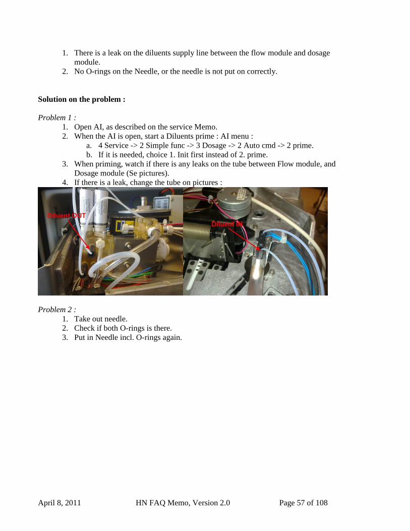
3. When priming, watch if there is any leaks on the tube between Flow module, and
Dosage module (Se pictures).
4. If there is a leak, change the tube on pictures :
Problem 2 :
1. Take out needle.
2. Check if both O-rings is there.
3. Put in Needle incl. O-rings again.
April 8, 2011 HN FAQ Memo, Version 2.0 Page 58 of 108
3.3 HN and Delaval C200 parlour cleaning.
This Chapter describes how the Herd Navigator and the Delaval C200 is working together
during the cleaning of parlour systems.
The parameters in the Delaval C200 and the Herd Navigator that have influence on the cleaning
process is described.
3.3.1 Abbreviations
HN: Herd Navigator
SMP: Sampling Valve
TOP: Top Valve
TRF: Transfer Valve
SPD: Speed Control Valve
DMP: Dump Valve
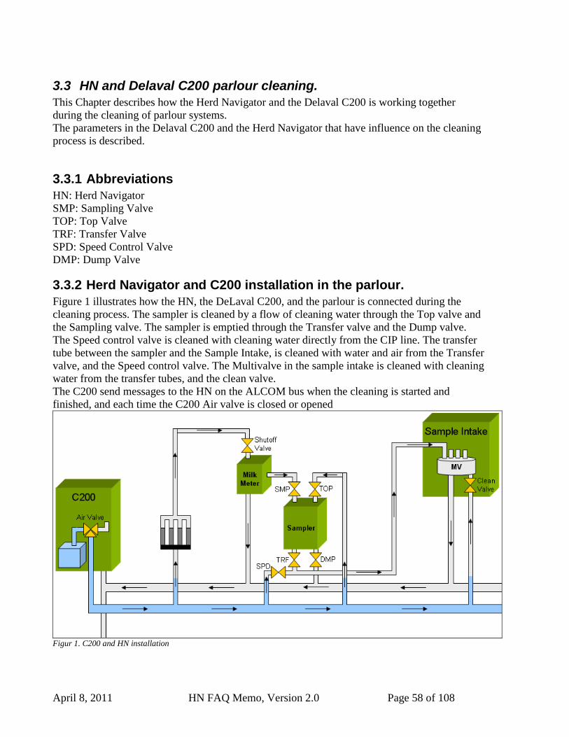
3.3.2 Herd Navigator and C200 installation in the parlour.
Figure 1 illustrates how the HN, the DeLaval C200, and the parlour is connected during the
cleaning process. The sampler is cleaned by a flow of cleaning water through the Top valve and
the Sampling valve. The sampler is emptied through the Transfer valve and the Dump valve.
The Speed control valve is cleaned with cleaning water directly from the CIP line. The transfer
tube between the sampler and the Sample Intake, is cleaned with water and air from the Transfer
valve, and the Speed control valve. The Multivalve in the sample intake is cleaned with cleaning
water from the transfer tubes, and the clean valve.
The C200 send messages to the HN on the ALCOM bus when the cleaning is started and
finished, and each time the C200 Air valve is closed or opened
Figur 1. C200 and HN installation
April 8, 2011 HN FAQ Memo, Version 2.0 Page 59 of 108
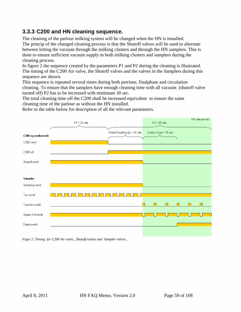
3.3.3 C200 and HN cleaning sequence.
The cleaning of the parlour milking system will be changed when the HN is installed.
The princip of the changed cleaning process is that the Shutoff valves will be used to alternate
between letting the vacuum through the milking clusters and through the HN samplers. This is
done to ensure sufficient vacuum supply in both milking clusters and samplers during the
cleaning process.
In figure 2 the sequence created by the parameters P1 and P2 during the cleaning is illustrated.
The timing of the C200 Air valve, the Shutoff valves and the valves in the Samplers during this
sequence are shown.
This sequence is repeated several times during both prerinse, finalphase and circulation
cleaning. To ensure that the samplers have enough cleaning time with all vacuum (shutoff valve
turned off) P2 has to be increased with minimum 30 sec.
The total cleaning time off the C200 shall be increased equivalent to ensure the same
cleaning time of the parlour as without the HN installed.
Refer to the table below for description of all the relevant parameters.
Figur 2. Timing for C200 Air valve,, Shutoff-valves and Sampler valves..
April 8, 2011 HN FAQ Memo, Version 2.0 Page 60 of 108
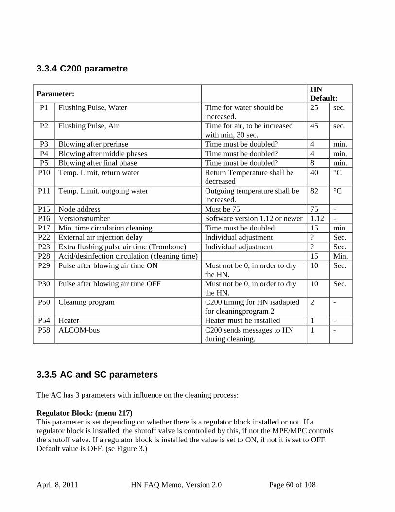
3.3.4 C200 parametre
Parameter: HN
Default:
P1 Flushing Pulse, Water Time for water should be
increased.
25 sec.
P2 Flushing Pulse, Air Time for air, to be increased
with min, 30 sec.
45 sec.
P3 Blowing after prerinse Time must be doubled? 4 min.
P4 Blowing after middle phases Time must be doubled? 4 min.
P5 Blowing after final phase Time must be doubled? 8 min.
P10 Temp. Limit, return water Return Temperature shall be
decreased
40 °C
P11 Temp. Limit, outgoing water Outgoing temperature shall be
increased.
82 °C
P15 Node address Must be 75 75 -
P16 Versionsnumber Software version 1.12 or newer 1.12 -
P17 Min. time circulation cleaning Time must be doubled 15 min.
P22 External air injection delay Individual adjustment ? Sec.
P23 Extra flushing pulse air time (Trombone) Individual adjustment ? Sec.
P28 Acid/desinfection circulation (cleaning time) 15 Min.
P29 Pulse after blowing air time ON Must not be 0, in order to dry
the HN.
10 Sec.
P30 Pulse after blowing air time OFF Must not be 0, in order to dry
the HN.
10 Sec.
P50 Cleaning program C200 timing for HN isadapted
for cleaningprogram 2
2 -
P54 Heater Heater must be installed 1 -
P58 ALCOM-bus C200 sends messages to HN
during cleaning.
1 -
3.3.5 AC and SC parameters
The AC has 3 parameters with influence on the cleaning process:
Regulator Block: (menu 217)
This parameter is set depending on whether there is a regulator block installed or not. If a
regulator block is installed, the shutoff valve is controlled by this, if not the MPE/MPC controls
the shutoff valve. If a regulator block is installed the value is set to ON, if not it is set to OFF.
Default value is OFF. (se Figure 3.)
April 8, 2011 HN FAQ Memo, Version 2.0 Page 61 of 108
Fig 3. Regulator block installed: yes=ON, No= OFF.
SC Water Passth (menu 2232).:
The value for SC WaterPassth. must always be equal to the value of the Water Passthrough
Time parameter in the SI. (See description in chapter 3.3.6)
Default value is 15 Sec. See figure 4.
Figurer 4. SC Water Passth. must be equal to Water Passthrough Time in SI.
SC Dump Close: (menu 222):
The value of the Dump Close parameter determines how long time the Dump valves are closed
after the Shutoff valves are closed. When the Dump Close time is passed the samplers are
emptied through the Dump valves.
The default value is 15 sec. See figure 5
Figur 5. SC Dump Close
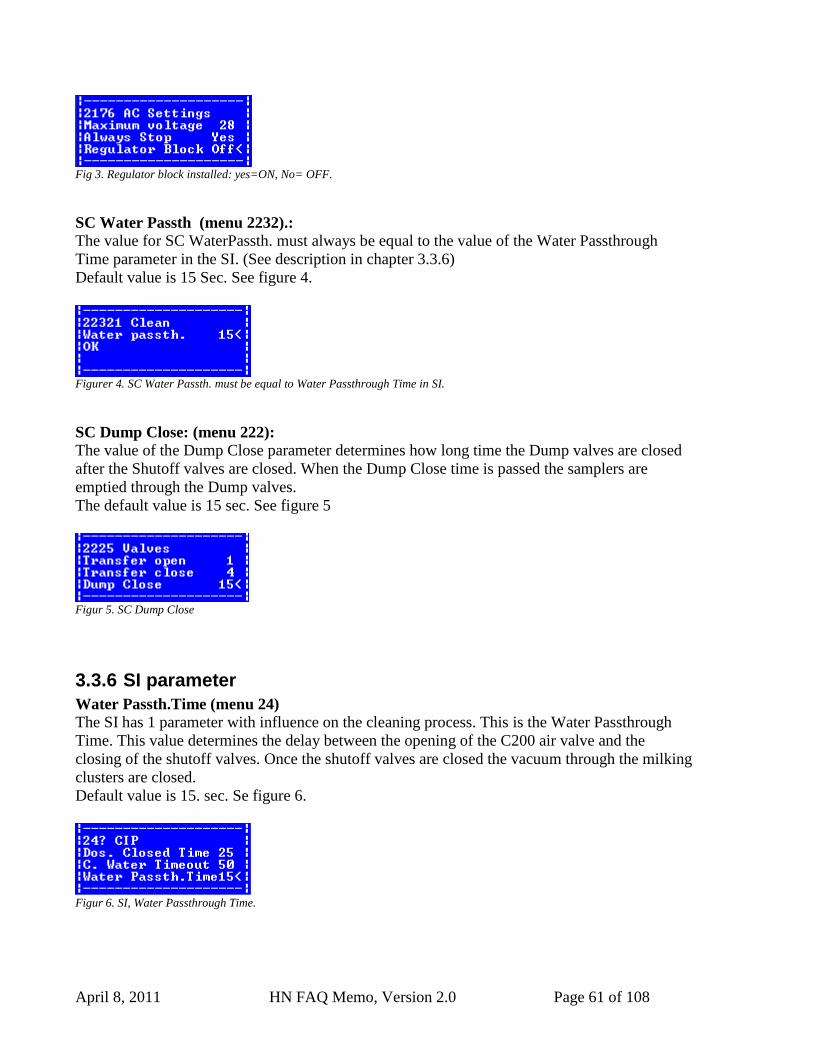
3.3.6 SI parameter
Water Passth.Time (menu 24)
The SI has 1 parameter with influence on the cleaning process. This is the Water Passthrough
Time. This value determines the delay between the opening of the C200 air valve and the
closing of the shutoff valves. Once the shutoff valves are closed the vacuum through the milking
clusters are closed.
Default value is 15. sec. Se figure 6.
Figur 6. SI, Water Passthrough Time.
April 8, 2011 HN FAQ Memo, Version 2.0 Page 62 of 108
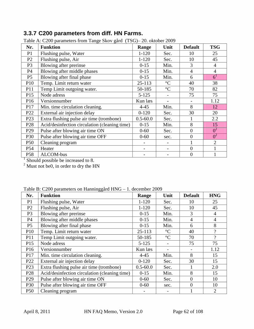
3.3.7 C200 parameters from diff. HN Farms.
Table A: C200 parameters from Tange Skov gård (TSG)– 20. oktober 2009
Nr. Funktion Range Unit Default TSG
P1 Flushing pulse, Water 1-120 Sec. 10 25
P2 Flushing pulse, Air 1-120 Sec. 10 45
P3 Blowing after prerinse 0-15 Min. 3 4
P4 Blowing after middle phases 0-15 Min. 4 4
P5 Blowing after final phase 0-15 Min. 6 61
P10 Temp. Limit return water 25-113 °C 40 38
P11 Temp Limit outgoing water. 50-185 °C 70 82
P15 Node adress 5-125 - 75 75
P16 Versionnumber Kun læs - - 1.12
P17 Min. time circulation cleaning. 4-45 Min. 8 12
P22 External air injection delay 0-120 Sec. 30 20
P23 Extra flushing pulse air time (trombone) 0.5-60.0 Sec. 1 2.2
P28 Acid/desinfection circulation (cleaning time) 0-15 Min. 8 15
P29 Pulse after blowing air time ON 0-60 Sec. 0 02
P30 Pulse after blowing air time OFF 0-60 sec. 0 02
P50 Cleaning program - - 1 2
P54 Heater - - 0 1
P58 ALCOM-bus - - 0 1 1 Should possible be increased to 8.
2 Must not be0, in order to dry the HN
Table B: C200 parameters on Hanninggård HNG – 1. december 2009
Nr. Funktion Range Unit Default HNG
P1 Flushing pulse, Water 1-120 Sec. 10 25
P2 Flushing pulse, Air 1-120 Sec. 10 45
P3 Blowing after prerinse 0-15 Min. 3 4
P4 Blowing after middle phases 0-15 Min. 4 4
P5 Blowing after final phase 0-15 Min. 6 8
P10 Temp. Limit return water 25-113 °C 40 ?
P11 Temp Limit outgoing water. 50-185 °C 70 ?
P15 Node adress 5-125 - 75 75
P16 Versionnumber Kun læs - - 1.12
P17 Min. time circulation cleaning. 4-45 Min. 8 15
P22 External air injection delay 0-120 Sec. 30 15
P23 Extra flushing pulse air time (trombone) 0.5-60.0 Sec. 1 2.0
P28 Acid/desinfection circulation (cleaning time) 0-15 Min. 8 15
P29 Pulse after blowing air time ON 0-60 Sec. 0 10
P30 Pulse after blowing air time OFF 0-60 sec. 0 10
P50 Cleaning program - - 1 2
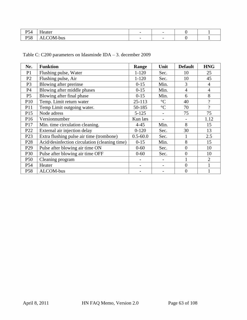
April 8, 2011 HN FAQ Memo, Version 2.0 Page 63 of 108
P54 Heater - - 0 1
P58 ALCOM-bus - - 0 1
Table C: C200 parameters on Idasminde IDA – 3. december 2009
Nr. Funktion Range Unit Default HNG
P1 Flushing pulse, Water 1-120 Sec. 10 25
P2 Flushing pulse, Air 1-120 Sec. 10 45
P3 Blowing after prerinse 0-15 Min. 3 4
P4 Blowing after middle phases 0-15 Min. 4 4
P5 Blowing after final phase 0-15 Min. 6 8
P10 Temp. Limit return water 25-113 °C 40 ?
P11 Temp Limit outgoing water. 50-185 °C 70 ?
P15 Node adress 5-125 - 75 75
P16 Versionnumber Kun læs - - 1.12
P17 Min. time circulation cleaning. 4-45 Min. 8 15
P22 External air injection delay 0-120 Sec. 30 13
P23 Extra flushing pulse air time (trombone) 0.5-60.0 Sec. 1 2.5
P28 Acid/desinfection circulation (cleaning time) 0-15 Min. 8 15
P29 Pulse after blowing air time ON 0-60 Sec. 0 10
P30 Pulse after blowing air time OFF 0-60 Sec. 0 10
P50 Cleaning program - - 1 2
P54 Heater - - 0 1
P58 ALCOM-bus - - 0 1
April 8, 2011 HN FAQ Memo, Version 2.0 Page 64 of 108
3.4 Sampler.
3.4.1 Recalibration of sampler transfer time.
Each sampler has an individually calibrated value for the “sampler transfer time”. The value
corresponds to the time for the sample to travel from the sampler to the BD3 detector in the
sample intake. The value is automatically calibrated during the first samples taken from the
samplers.
After a complete service or upgrade of samplers, the value has to be recalibrated. The value is
automatically calibrated if the value is reset to 0.
The value can be reset in the SI menu. The value can be reset for each sampler individually or
for all samplers. If work has been done on only some of the samplers, these should be reset
individually.
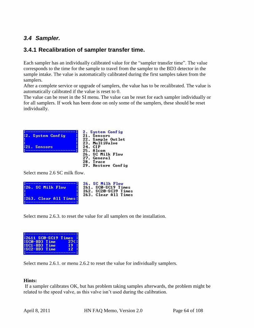
Select menu 2.6 SC milk flow.
Select menu 2.6.3. to reset the value for all samplers on the installation.
Select menu 2.6.1. or menu 2.6.2 to reset the value for individually samplers.
Hints:
If a sampler calibrates OK, but has problem taking samples afterwards, the problem might be
related to the speed valve, as this valve isn‟t used during the calibration.
April 8, 2011 HN FAQ Memo, Version 2.0 Page 65 of 108
If a sampler has problems to calibrate, this could also be related to the speed valve, if it‟s
constantly open.
4 INFO:
4.1 Menu overview for the Sample Intake, (SI)
1. Maintenance
11. Prime Deterg.
12. AI CIP
13. MV CIP
2. System Config
21. Sensors
22. Sample Outlet
23. MultiValve
24. CIP
25. Alcom
26. SC Milk Flow
261. SC0-SC19 Times
262. SC20-SC39 Times
263. Clear All Times
27. General
28. Trace
281. Show Trace
282. Set Trace level
283. Trace all from
284. Refresh trace
285. Clear trace
29. Restore Config
291. All
292. Central
293. Bus Handling
294. MMI
295. Supervision
296. CIP Handling
297. Sample Object
298. MultiValve
299. Sample Transfer
290. Bubble Detect
3. Information
31. System
April 8, 2011 HN FAQ Memo, Version 2.0 Page 66 of 108
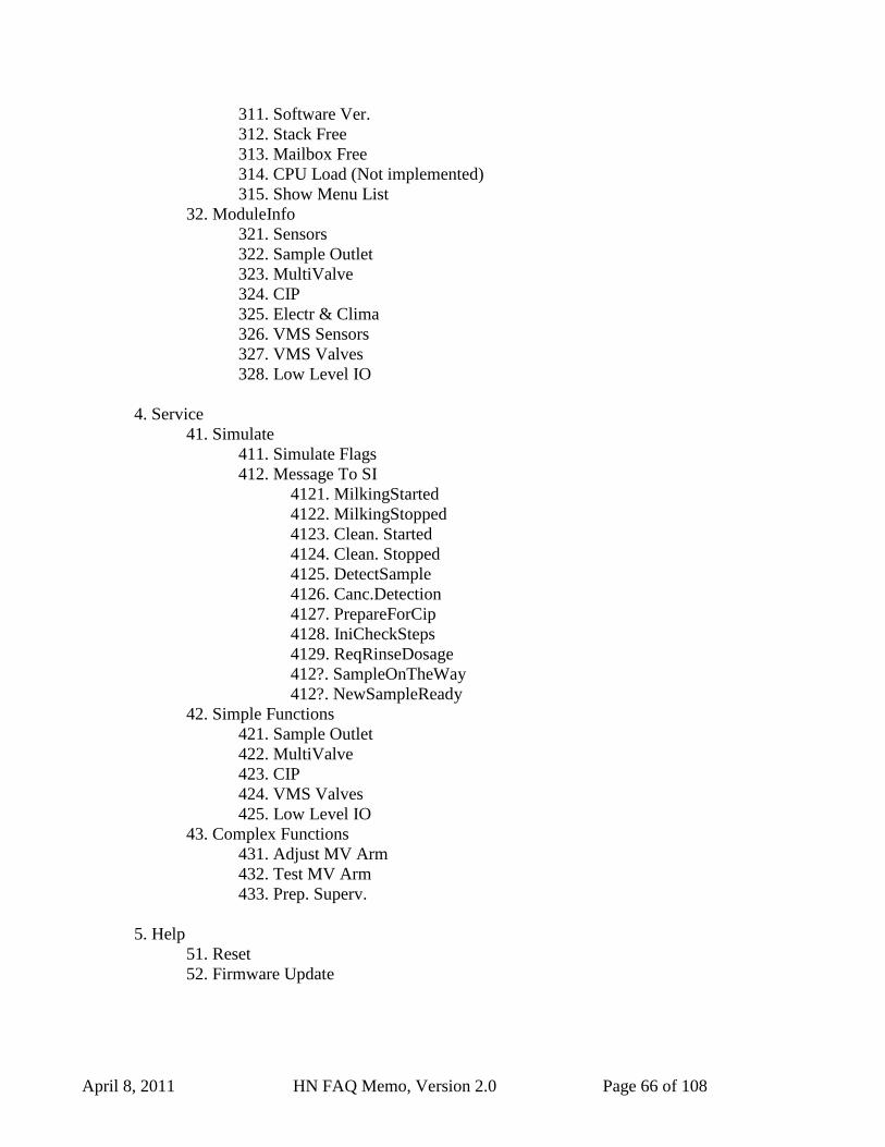
311. Software Ver.
312. Stack Free
313. Mailbox Free
314. CPU Load (Not implemented)
315. Show Menu List
32. ModuleInfo
321. Sensors
322. Sample Outlet
323. MultiValve
324. CIP
325. Electr & Clima
326. VMS Sensors
327. VMS Valves
328. Low Level IO
4. Service
41. Simulate
411. Simulate Flags
412. Message To SI
4121. MilkingStarted
4122. MilkingStopped
4123. Clean. Started
4124. Clean. Stopped
4125. DetectSample
4126. Canc.Detection
4127. PrepareForCip
4128. IniCheckSteps
4129. ReqRinseDosage
412?. SampleOnTheWay
412?. NewSampleReady
42. Simple Functions
421. Sample Outlet
422. MultiValve
423. CIP
424. VMS Valves
425. Low Level IO
43. Complex Functions
431. Adjust MV Arm
432. Test MV Arm
433. Prep. Superv.
5. Help
51. Reset
52. Firmware Update
April 8, 2011 HN FAQ Memo, Version 2.0 Page 67 of 108
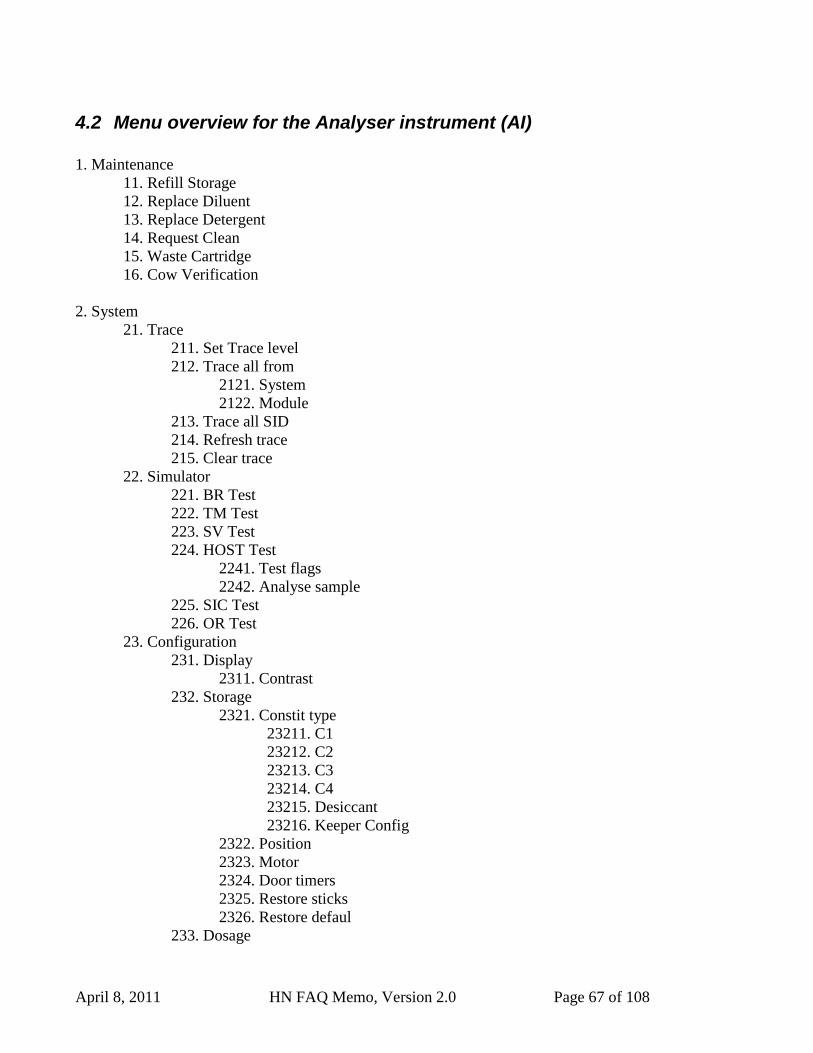
4.2 Menu overview for the Analyser instrument (AI)
1. Maintenance
11. Refill Storage
12. Replace Diluent
13. Replace Detergent
14. Request Clean
15. Waste Cartridge
16. Cow Verification
2. System
21. Trace
211. Set Trace level
212. Trace all from
2121. System
2122. Module
213. Trace all SID
214. Refresh trace
215. Clear trace
22. Simulator
221. BR Test
222. TM Test
223. SV Test
224. HOST Test
2241. Test flags
2242. Analyse sample
225. SIC Test
226. OR Test
23. Configuration
231. Display
2311. Contrast
232. Storage
2321. Constit type
23211. C1
23212. C2
23213. C3
23214. C4
23215. Desiccant
23216. Keeper Config
2322. Position
2323. Motor
2324. Door timers
2325. Restore sticks
2326. Restore defaul
233. Dosage
April 8, 2011 HN FAQ Memo, Version 2.0 Page 68 of 108
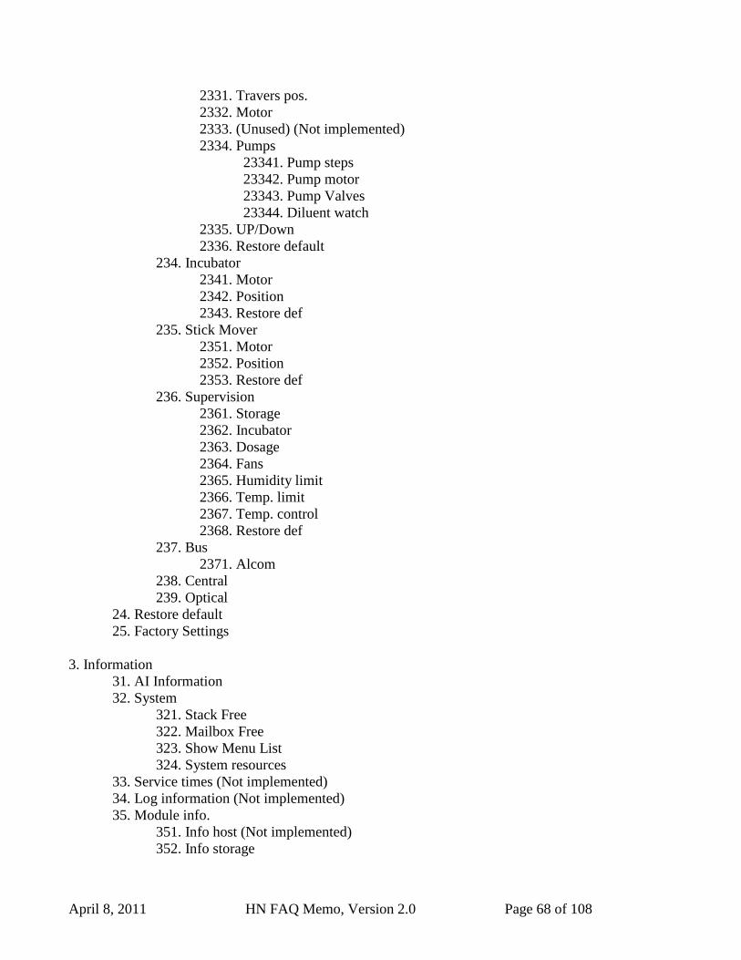
2331. Travers pos.
2332. Motor
2333. (Unused) (Not implemented)
2334. Pumps
23341. Pump steps
23342. Pump motor
23343. Pump Valves
23344. Diluent watch
2335. UP/Down
2336. Restore default
234. Incubator
2341. Motor
2342. Position
2343. Restore def
235. Stick Mover
2351. Motor
2352. Position
2353. Restore def
236. Supervision
2361. Storage
2362. Incubator
2363. Dosage
2364. Fans
2365. Humidity limit
2366. Temp. limit
2367. Temp. control
2368. Restore def
237. Bus
2371. Alcom
238. Central
239. Optical
24. Restore default
25. Factory Settings
3. Information
31. AI Information
32. System
321. Stack Free
322. Mailbox Free
323. Show Menu List
324. System resources
33. Service times (Not implemented)
34. Log information (Not implemented)
35. Module info.
351. Info host (Not implemented)
352. Info storage
April 8, 2011 HN FAQ Memo, Version 2.0 Page 69 of 108
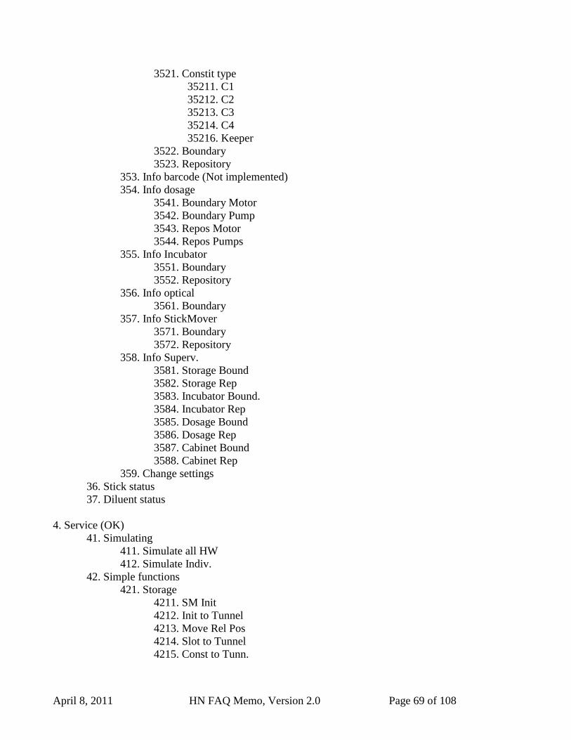
3521. Constit type
35211. C1
35212. C2
35213. C3
35214. C4
35216. Keeper
3522. Boundary
3523. Repository
353. Info barcode (Not implemented)
354. Info dosage
3541. Boundary Motor
3542. Boundary Pump
3543. Repos Motor
3544. Repos Pumps
355. Info Incubator
3551. Boundary
3552. Repository
356. Info optical
3561. Boundary
357. Info StickMover
3571. Boundary
3572. Repository
358. Info Superv.
3581. Storage Bound
3582. Storage Rep
3583. Incubator Bound.
3584. Incubator Rep
3585. Dosage Bound
3586. Dosage Rep
3587. Cabinet Bound
3588. Cabinet Rep
359. Change settings
36. Stick status
37. Diluent status
4. Service (OK)
41. Simulating
411. Simulate all HW
412. Simulate Indiv.
42. Simple functions
421. Storage
4211. SM Init
4212. Init to Tunnel
4213. Move Rel Pos
4214. Slot to Tunnel
4215. Const to Tunn.
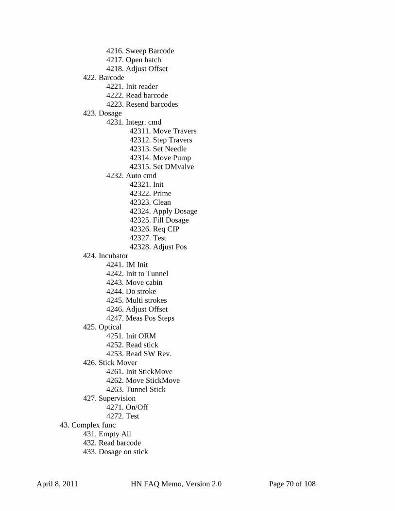
April 8, 2011 HN FAQ Memo, Version 2.0 Page 70 of 108
4216. Sweep Barcode
4217. Open hatch
4218. Adjust Offset
422. Barcode
4221. Init reader
4222. Read barcode
4223. Resend barcodes
423. Dosage
4231. Integr. cmd
42311. Move Travers
42312. Step Travers
42313. Set Needle
42314. Move Pump
42315. Set DMvalve
4232. Auto cmd
42321. Init
42322. Prime
42323. Clean
42324. Apply Dosage
42325. Fill Dosage
42326. Req CIP
42327. Test
42328. Adjust Pos
424. Incubator
4241. IM Init
4242. Init to Tunnel
4243. Move cabin
4244. Do stroke
4245. Multi strokes
4246. Adjust Offset
4247. Meas Pos Steps
425. Optical
4251. Init ORM
4252. Read stick
4253. Read SW Rev.
426. Stick Mover
4261. Init StickMove
4262. Move StickMove
4263. Tunnel Stick
427. Supervision
4271. On/Off
4272. Test
43. Complex func
431. Empty All
432. Read barcode
433. Dosage on stick
April 8, 2011 HN FAQ Memo, Version 2.0 Page 71 of 108
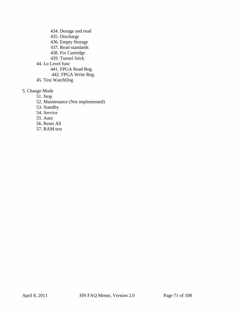
434. Dosage and read
435. Discharge
436. Empty Storage
437. Read standards
438. Fix Cartridge
439. Tunnel Stick
44. Lo Level func
441. FPGA Read Reg.
442. FPGA Write Reg.
45. Test WatchDog
5. Change Mode
51. Stop
52. Maintenance (Not implemented)
53. Standby
54. Service
55. Auto
56. Reset All
57. RAM test
April 8, 2011 HN FAQ Memo, Version 2.0 Page 72 of 108
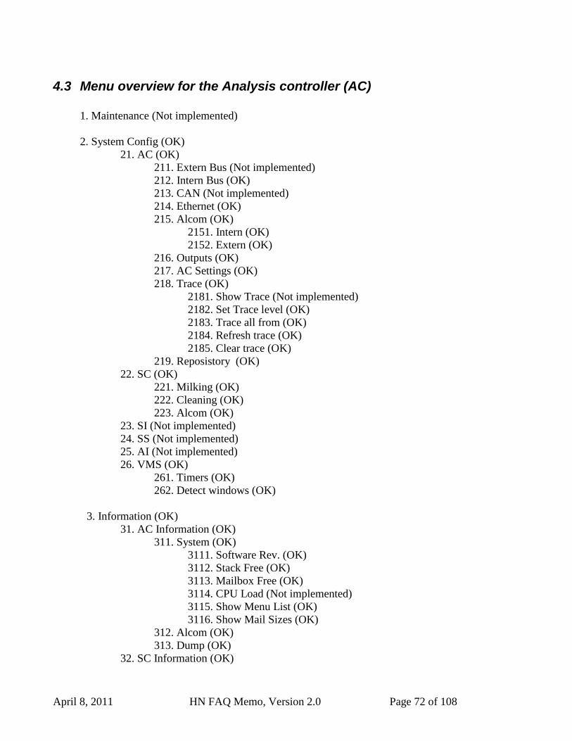
4.3 Menu overview for the Analysis controller (AC)
1. Maintenance (Not implemented)
2. System Config (OK)
21. AC (OK)
211. Extern Bus (Not implemented)
212. Intern Bus (OK)
213. CAN (Not implemented)
214. Ethernet (OK)
215. Alcom (OK)
2151. Intern (OK)
2152. Extern (OK)
216. Outputs (OK)
217. AC Settings (OK)
218. Trace (OK)
2181. Show Trace (Not implemented)
2182. Set Trace level (OK)
2183. Trace all from (OK)
2184. Refresh trace (OK)
2185. Clear trace (OK)
219. Reposistory (OK)
22. SC (OK)
221. Milking (OK)
222. Cleaning (OK)
223. Alcom (OK)
23. SI (Not implemented)
24. SS (Not implemented)
25. AI (Not implemented)
26. VMS (OK)
261. Timers (OK)
262. Detect windows (OK)
3. Information (OK)
31. AC Information (OK)
311. System (OK)
3111. Software Rev. (OK)
3112. Stack Free (OK)
3113. Mailbox Free (OK)
3114. CPU Load (Not implemented)
3115. Show Menu List (OK)
3116. Show Mail Sizes (OK)
312. Alcom (OK)
313. Dump (OK)
32. SC Information (OK)
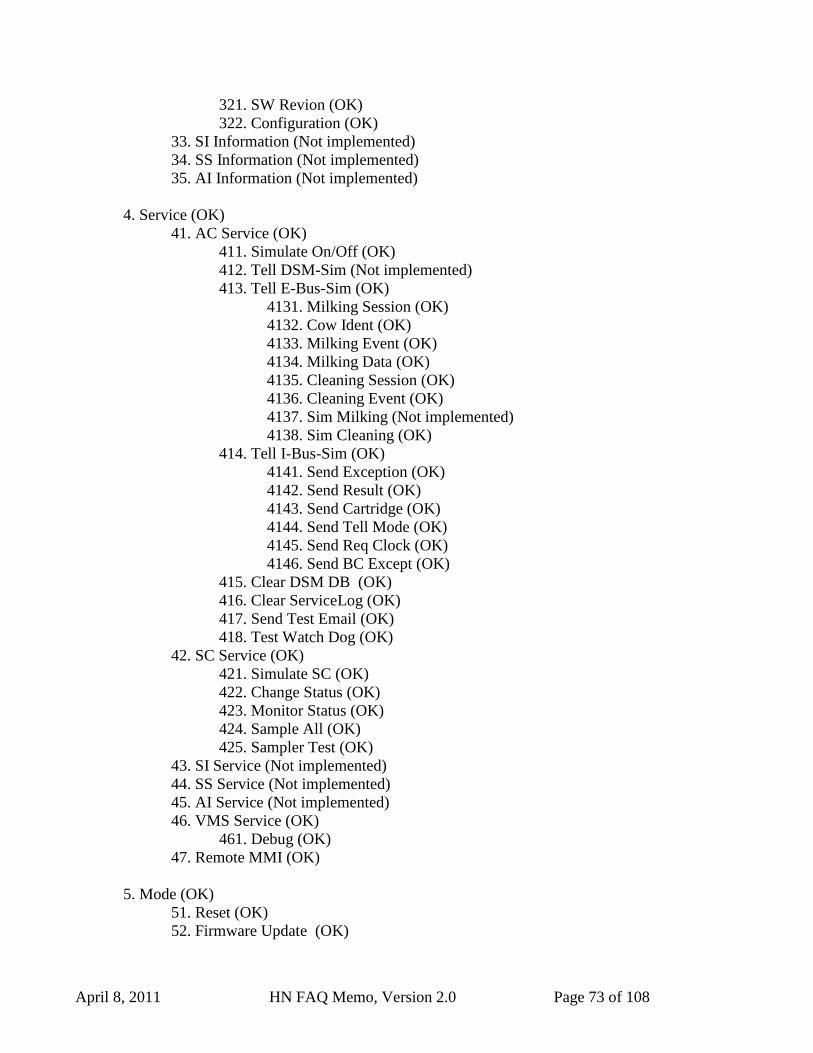
April 8, 2011 HN FAQ Memo, Version 2.0 Page 73 of 108
321. SW Revion (OK)
322. Configuration (OK)
33. SI Information (Not implemented)
34. SS Information (Not implemented)
35. AI Information (Not implemented)
4. Service (OK)
41. AC Service (OK)
411. Simulate On/Off (OK)
412. Tell DSM-Sim (Not implemented)
413. Tell E-Bus-Sim (OK)
4131. Milking Session (OK)
4132. Cow Ident (OK)
4133. Milking Event (OK)
4134. Milking Data (OK)
4135. Cleaning Session (OK)
4136. Cleaning Event (OK)
4137. Sim Milking (Not implemented)
4138. Sim Cleaning (OK)
414. Tell I-Bus-Sim (OK)
4141. Send Exception (OK)
4142. Send Result (OK)
4143. Send Cartridge (OK)
4144. Send Tell Mode (OK)
4145. Send Req Clock (OK)
4146. Send BC Except (OK)
415. Clear DSM DB (OK)
416. Clear ServiceLog (OK)
417. Send Test Email (OK)
418. Test Watch Dog (OK)
42. SC Service (OK)
421. Simulate SC (OK)
422. Change Status (OK)
423. Monitor Status (OK)
424. Sample All (OK)
425. Sampler Test (OK)
43. SI Service (Not implemented)
44. SS Service (Not implemented)
45. AI Service (Not implemented)
46. VMS Service (OK)
461. Debug (OK)
47. Remote MMI (OK)
5. Mode (OK)
51. Reset (OK)
52. Firmware Update (OK)
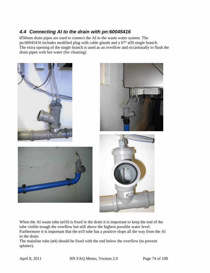
April 8, 2011 HN FAQ Memo, Version 2.0 Page 74 of 108
4.4 Connecting AI to the drain with pn:60045416
Ø50mm drain pipes are used to connect the AI to the waste water system. The
pn:60045416 includes modified plug with cable glands and a 67° ø50 single branch.
The extra opening of the single branch is used as an overflow and occasionally to flush the
drain pipes with hot water (for cleaning).
When the AI waste tube (ø10) is fixed in the drain it is important to keep the end of the
tube visible trough the overflow but still above the highest possible water level.
Furthermore it is important that the ø10 tube has a positive slope all the way from the AI
to the drain.
The mainline tube (ø4) should be fixed with the end below the overflow (to prevent
splatter).
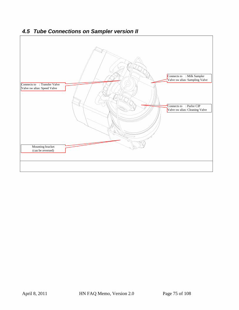
April 8, 2011 HN FAQ Memo, Version 2.0 Page 75 of 108
4.5 Tube Connections on Sampler version II
Connects to : Parlor CIP
Valve sw alias: Cleaning Valve
Mounting bracket
(can be reversed)
Connects to : Milk Sampler
Valve sw alias: Sampling Valve
Connects to : Transfer Valve
Valve sw alias: Speed Valve
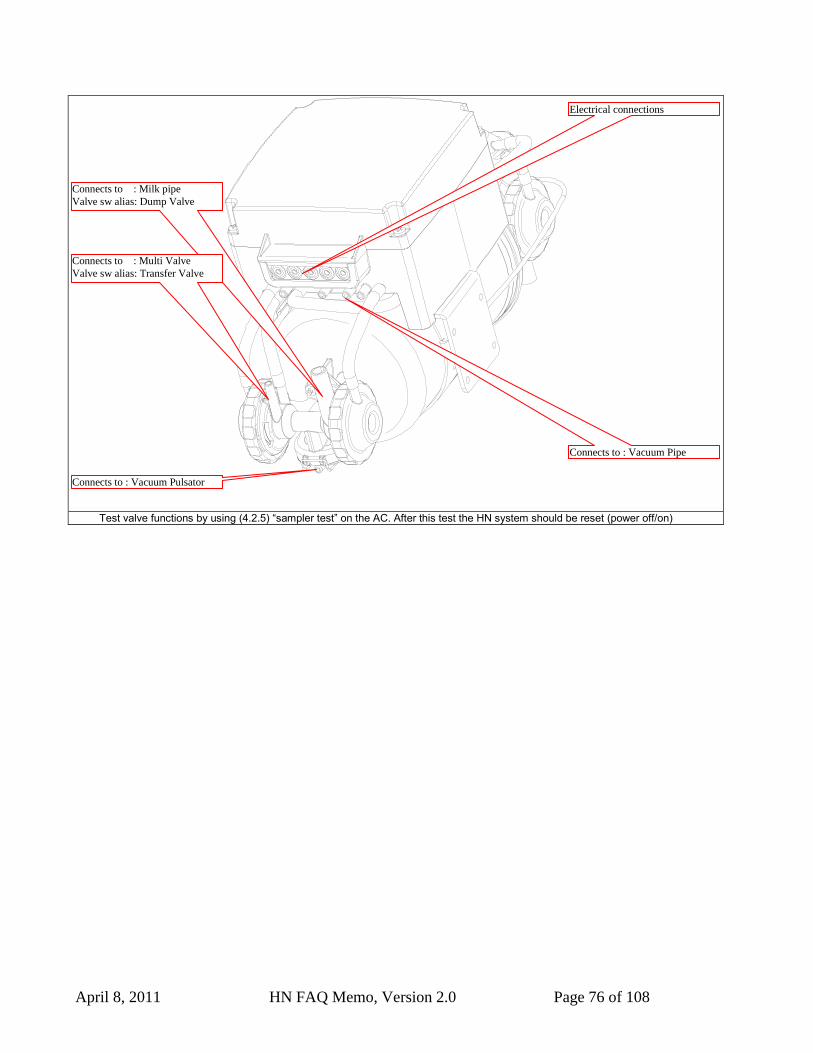
April 8, 2011 HN FAQ Memo, Version 2.0 Page 76 of 108
Test valve functions by using (4.2.5) “sampler test” on the AC. After this test the HN system should be reset (power off/on)
Connects to : Milk pipe
Valve sw alias: Dump Valve
Connects to : Multi Valve
Valve sw alias: Transfer Valve
Connects to : Vacuum Pipe
Electrical connections
Connects to : Vacuum Pulsator
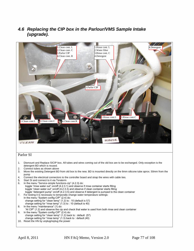
April 8, 2011 HN FAQ Memo, Version 2.0 Page 77 of 108
4.6 Replacing the CIP box in the Parlour/VMS Sample Intake (upgrade).
Parlor SI
1. Dismount and Replace SICIP box. All tubes and wires coming out of the old box are to be exchanged. Only exception is the
detergent BD which is reused. 2. Connect tubes as shown above 3. Move the existing Detergent BD from old box to the new. BD is mounted directly on the 6mm silicone tube aprox. 50mm from the
pump 4. Connect the electrical connectors to the controller board and strap the wires with cable ties. 5. Start SI and connect to it via Teraterm 6. In the menu “Service-simple functions-cip” (4.2.3) do:
toggle “rinse water out” on/off (4.2.3.1) and observe if rinse container starts filling toggle “clean water out” on/off (4.2.3.3) and observe if clean container starts filling toggle “detergent pump” on/off (4.2.3.5) and observe if detergent is pumped to the clean container
7. For testing it is necessary to temporally change water temperature settings: In the menu “System config-CIP” (2.4) do: change setting for “clean temp” (1.2) to : 10 (default is 57) change setting for “rinse temp” (1.3) to : 10 (default is 40)
8. In the menu “maintenance” (1) do: “AI CIP” (1.2) and observe the cip and check that water is used from both rinse and clean container
9. In the menu “System config-CIP” (2.4) do: change setting for “clean temp” (1.2) back to : default (57) change setting for “rinse temp” (1.3) back to : default (40)
10. Reset the HN by unplug/replug the power
1.Clean cont.L
1.Clean cont. L
2.Clean cont. C
3.Parlor CIP
4.Clean cont. R
1.Rinse cont. L
2.Water filter
3.Rinse cont. C
4.Detergent
2.Clean cont.C 4.Clean cont.R
3.Parlor CIP
4.Detergent
1.Rinse cont.L 3.Rinse cont.C
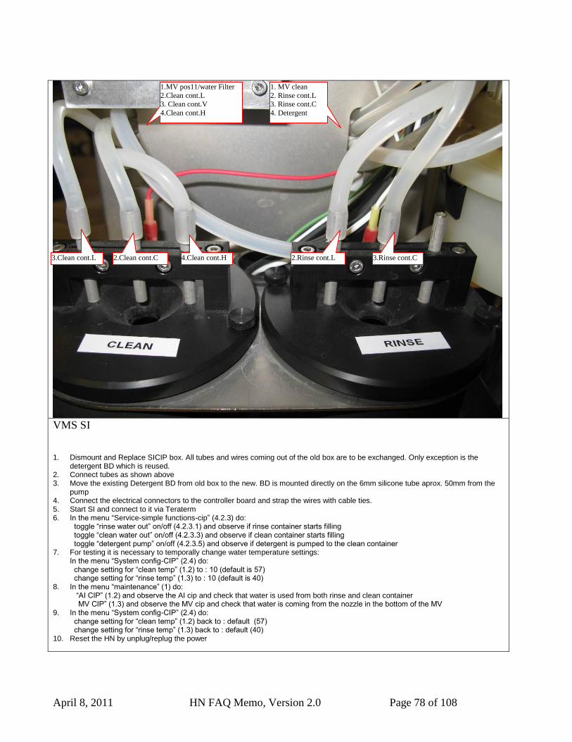
April 8, 2011 HN FAQ Memo, Version 2.0 Page 78 of 108
VMS SI
1. Dismount and Replace SICIP box. All tubes and wires coming out of the old box are to be exchanged. Only exception is the detergent BD which is reused.
2. Connect tubes as shown above 3. Move the existing Detergent BD from old box to the new. BD is mounted directly on the 6mm silicone tube aprox. 50mm from the
pump 4. Connect the electrical connectors to the controller board and strap the wires with cable ties. 5. Start SI and connect to it via Teraterm 6. In the menu “Service-simple functions-cip” (4.2.3) do:
toggle “rinse water out” on/off (4.2.3.1) and observe if rinse container starts filling toggle “clean water out” on/off (4.2.3.3) and observe if clean container starts filling toggle “detergent pump” on/off (4.2.3.5) and observe if detergent is pumped to the clean container
7. For testing it is necessary to temporally change water temperature settings: In the menu “System config-CIP” (2.4) do: change setting for “clean temp” (1.2) to : 10 (default is 57) change setting for “rinse temp” (1.3) to : 10 (default is 40)
8. In the menu “maintenance” (1) do: “AI CIP” (1.2) and observe the AI cip and check that water is used from both rinse and clean container MV CIP” (1.3) and observe the MV cip and check that water is coming from the nozzle in the bottom of the MV
9. In the menu “System config-CIP” (2.4) do: change setting for “clean temp” (1.2) back to : default (57) change setting for “rinse temp” (1.3) back to : default (40)
10. Reset the HN by unplug/replug the power
3.Clean cont.L
1.MV pos11/water Filter
2.Clean cont.L
3. Clean cont.V
4.Clean cont.H
1. MV clean
2. Rinse cont.L
3. Rinse cont.C
4. Detergent
2.Clean cont.C 4.Clean cont.H 2.Rinse cont.L 3.Rinse cont.C
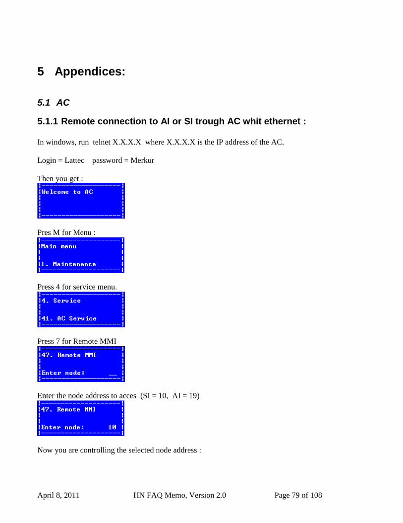
April 8, 2011 HN FAQ Memo, Version 2.0 Page 79 of 108
5 Appendices:
5.1 AC
5.1.1 Remote connection to AI or SI trough AC whit ethernet :
In windows, run telnet X.X.X.X where X.X.X.X is the IP address of the AC.
Login = Lattec password = Merkur
Then you get :
Pres M for Menu :
Press 4 for service menu.
Press 7 for Remote MMI
Enter the node address to acces (SI = 10, AI = 19)
Now you are controlling the selected node address :
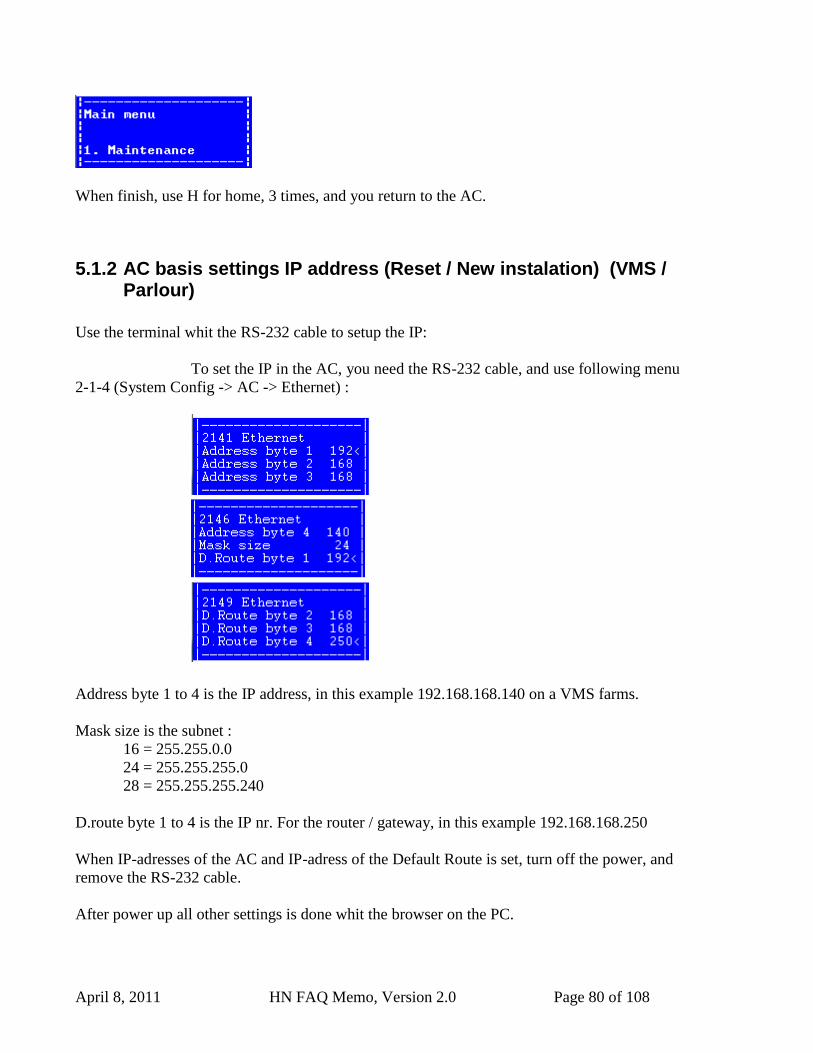
April 8, 2011 HN FAQ Memo, Version 2.0 Page 80 of 108
When finish, use H for home, 3 times, and you return to the AC.
5.1.2 AC basis settings IP address (Reset / New instalation) (VMS / Parlour)
Use the terminal whit the RS-232 cable to setup the IP:
To set the IP in the AC, you need the RS-232 cable, and use following menu
2-1-4 (System Config -> AC -> Ethernet) :
Address byte 1 to 4 is the IP address, in this example 192.168.168.140 on a VMS farms.
Mask size is the subnet :
16 = 255.255.0.0
24 = 255.255.255.0
28 = 255.255.255.240
D.route byte 1 to 4 is the IP nr. For the router / gateway, in this example 192.168.168.250
When IP-adresses of the AC and IP-adress of the Default Route is set, turn off the power, and
remove the RS-232 cable.
After power up all other settings is done whit the browser on the PC.
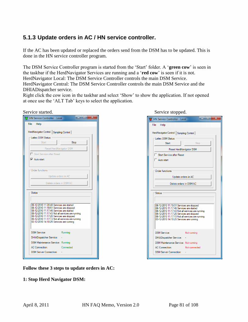
April 8, 2011 HN FAQ Memo, Version 2.0 Page 81 of 108
5.1.3 Update orders in AC / HN service controller.
If the AC has been updated or replaced the orders send from the DSM has to be updated. This is
done in the HN service controller program.
The DSM Service Controller program is started from the „Start‟ folder. A „green cow‟ is seen in
the taskbar if the HerdNavigator Services are running and a „red cow‟ is seen if it is not.
HerdNavigator Local: The DSM Service Controller controls the main DSM Service.
HerdNavigator Central: The DSM Service Controller controls the main DSM Service and the
DHIADispatcher service.
Right click the cow icon in the taskbar and select „Show‟ to show the application. If not opened
at once use the „ALT Tab‟ keys to select the application.
Service started. Service stopped.
Follow these 3 steps to update orders in AC:
1: Stop Herd Navigator DSM:
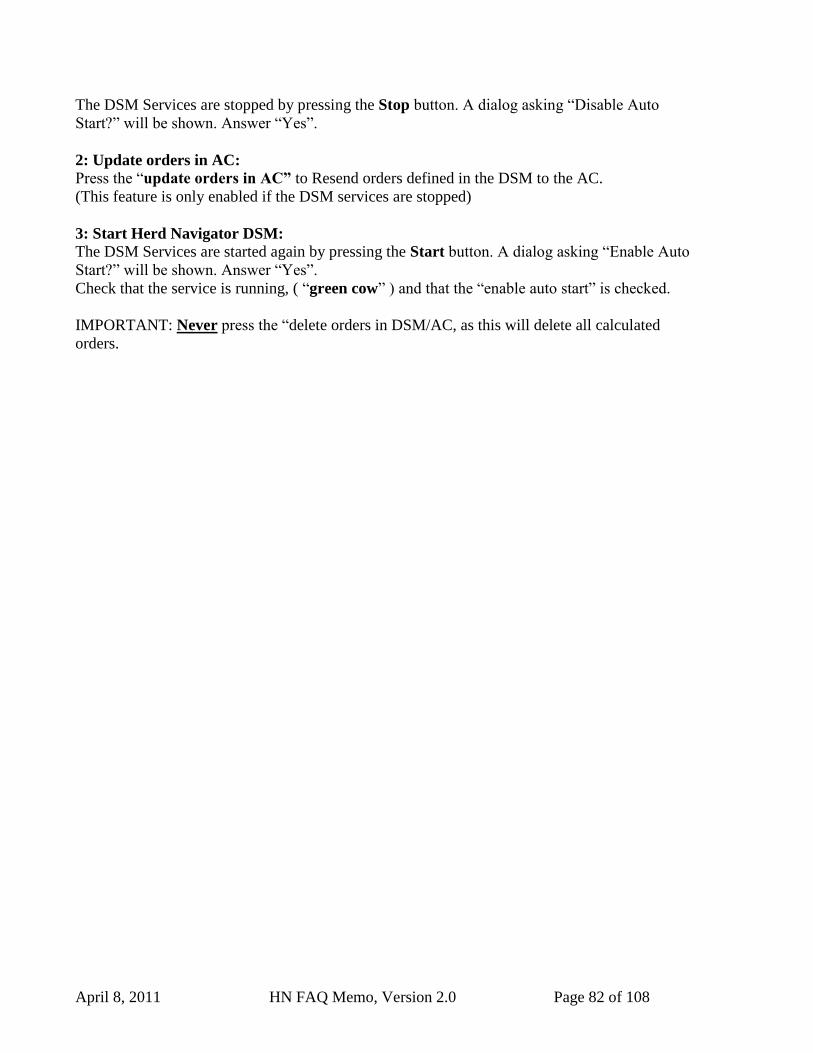
April 8, 2011 HN FAQ Memo, Version 2.0 Page 82 of 108
The DSM Services are stopped by pressing the Stop button. A dialog asking “Disable Auto
Start?” will be shown. Answer “Yes”.
2: Update orders in AC:
Press the “update orders in AC” to Resend orders defined in the DSM to the AC.
(This feature is only enabled if the DSM services are stopped)
3: Start Herd Navigator DSM:
The DSM Services are started again by pressing the Start button. A dialog asking “Enable Auto
Start?” will be shown. Answer “Yes”.
Check that the service is running, ( “green cow” ) and that the “enable auto start” is checked.
IMPORTANT: Never press the “delete orders in DSM/AC, as this will delete all calculated
orders.
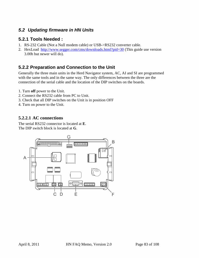
April 8, 2011 HN FAQ Memo, Version 2.0 Page 83 of 108
5.2 Updating firmware in HN Units
5.2.1 Tools Needed :
1. RS-232 Cable (Not a Null modem cable) or USB->RS232 converter cable.
2. HexLoad http://www.segger.com/cms/downloads.html?pid=30 (This guide use version
3.00h but newer will do).
5.2.2 Preparation and Connection to the Unit
Generally the three main units in the Herd Navigator system, AC, AI and SI are programmed
with the same tools and in the same way. The only differences between the three are the
connection of the serial cable and the location of the DIP switches on the boards.
1. Turn off power to the Unit.
2. Connect the RS232 cable from PC to Unit.
3. Check that all DIP switches on the Unit is in position OFF
4. Turn on power to the Unit.
5.2.2.1 AC connections
The serial RS232 connector is located at E.
The DIP switch block is located at G.
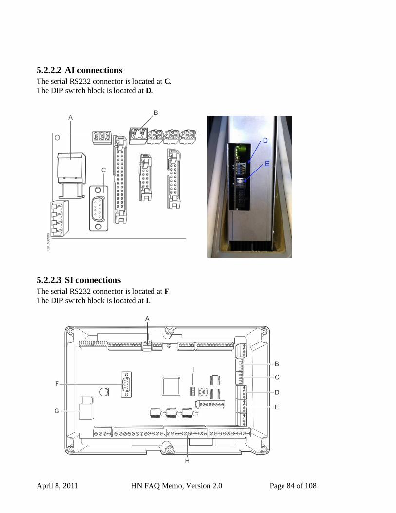
April 8, 2011 HN FAQ Memo, Version 2.0 Page 84 of 108
5.2.2.2 AI connections
The serial RS232 connector is located at C.
The DIP switch block is located at D.
5.2.2.3 SI connections
The serial RS232 connector is located at F.
The DIP switch block is located at I.
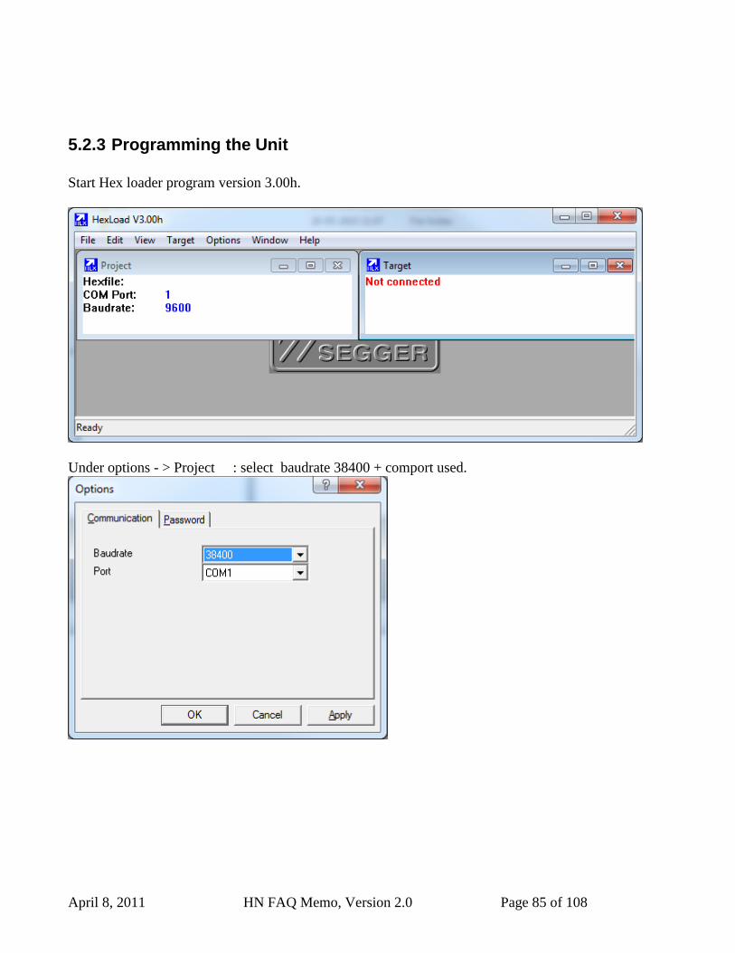
April 8, 2011 HN FAQ Memo, Version 2.0 Page 85 of 108
5.2.3 Programming the Unit
Start Hex loader program version 3.00h.
Under options - > Project : select baudrate 38400 + comport used.
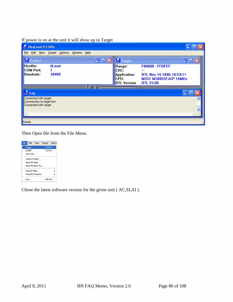
April 8, 2011 HN FAQ Memo, Version 2.0 Page 86 of 108
If power is on at the unit it will show up in Target
Then Open file from the File Menu.
Chose the latest software version for the given unit ( AC,SI,AI ).
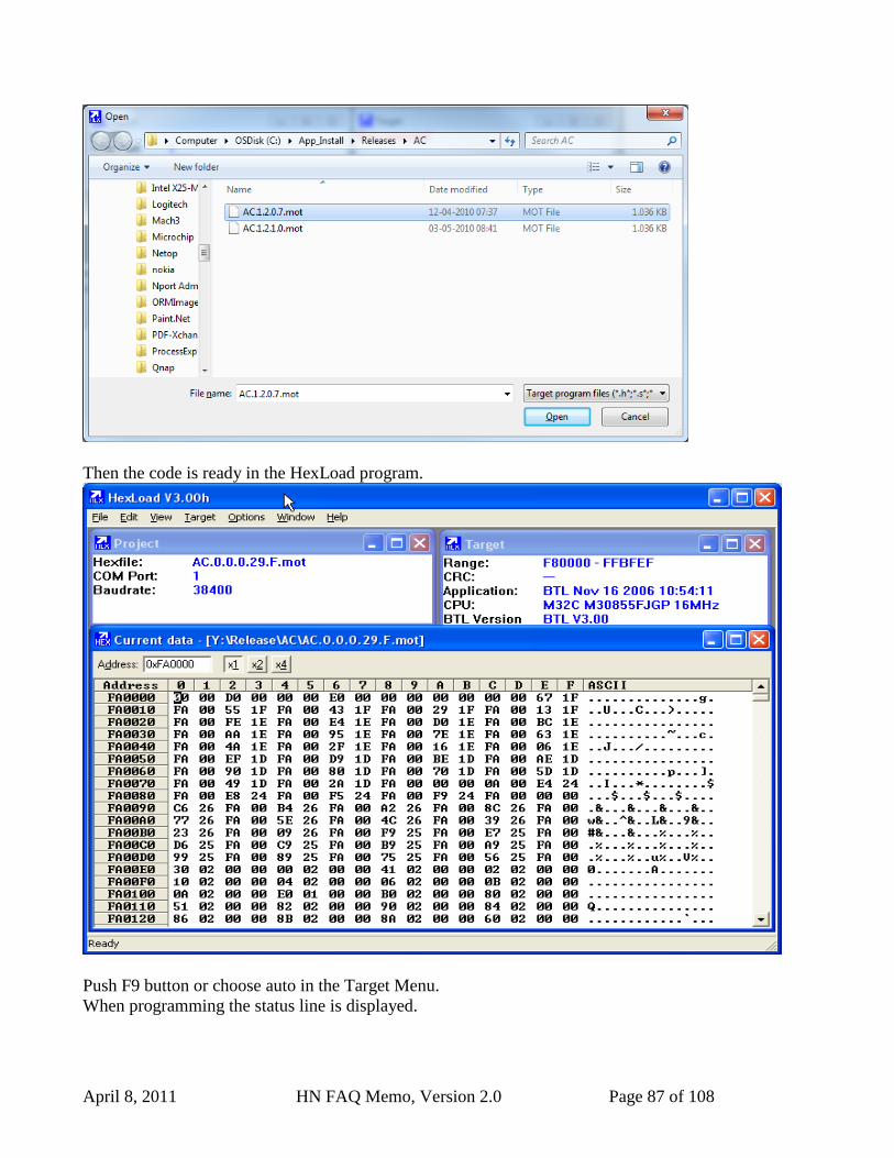
April 8, 2011 HN FAQ Memo, Version 2.0 Page 87 of 108
Then the code is ready in the HexLoad program.
Push F9 button or choose auto in the Target Menu.
When programming the status line is displayed.
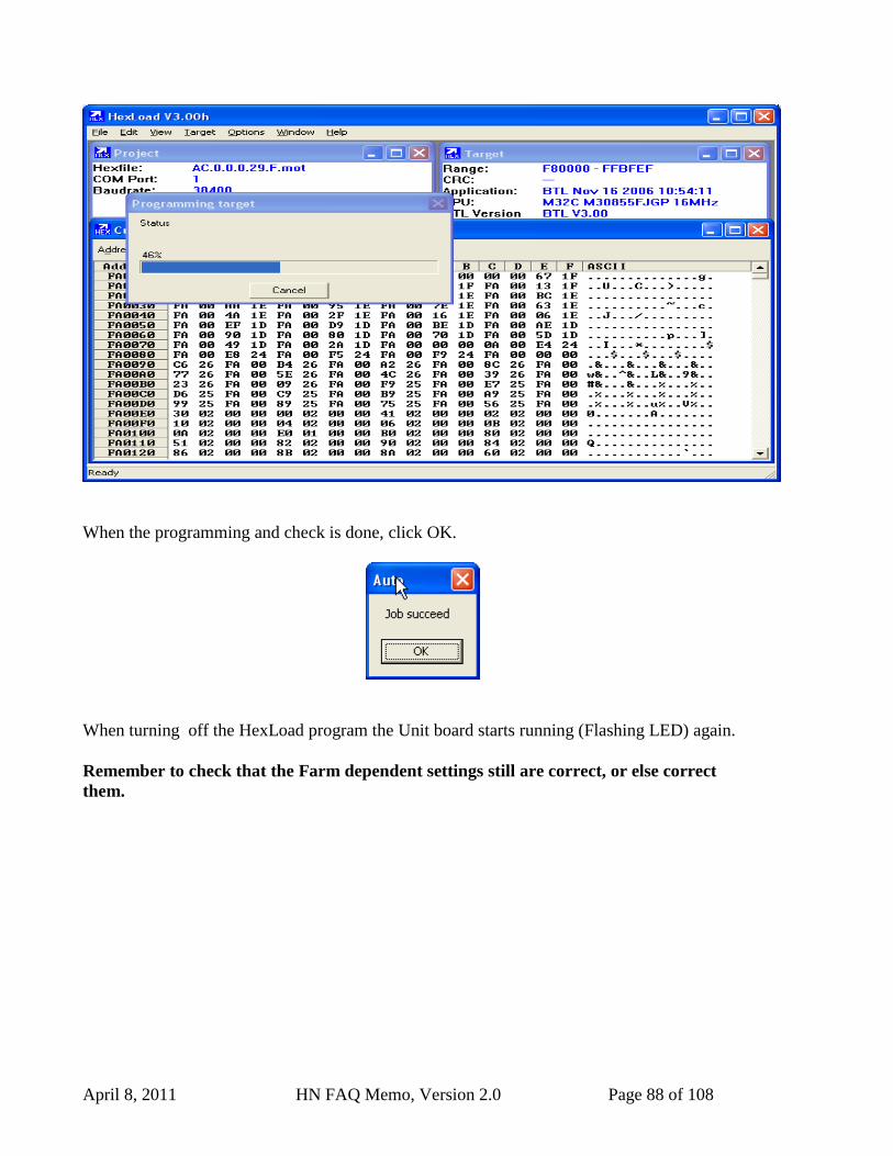
April 8, 2011 HN FAQ Memo, Version 2.0 Page 88 of 108
When the programming and check is done, click OK.
When turning off the HexLoad program the Unit board starts running (Flashing LED) again.
Remember to check that the Farm dependent settings still are correct, or else correct
them.
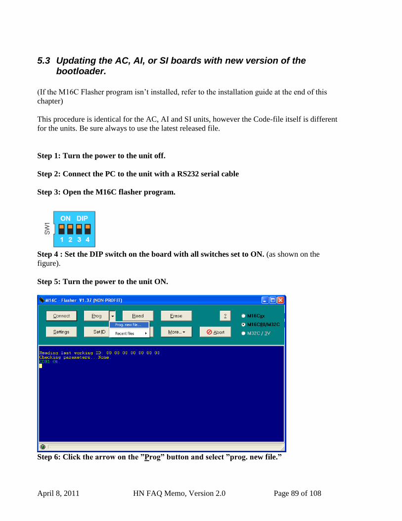
April 8, 2011 HN FAQ Memo, Version 2.0 Page 89 of 108
5.3 Updating the AC, AI, or SI boards with new version of the bootloader.
(If the M16C Flasher program isn‟t installed, refer to the installation guide at the end of this
chapter)
This procedure is identical for the AC, AI and SI units, however the Code-file itself is different
for the units. Be sure always to use the latest released file.
Step 1: Turn the power to the unit off.
Step 2: Connect the PC to the unit with a RS232 serial cable
Step 3: Open the M16C flasher program.
Step 4 : Set the DIP switch on the board with all switches set to ON. (as shown on the
figure).
Step 5: Turn the power to the unit ON.
Step 6: Click the arrow on the ”Prog” button and select ”prog. new file.”
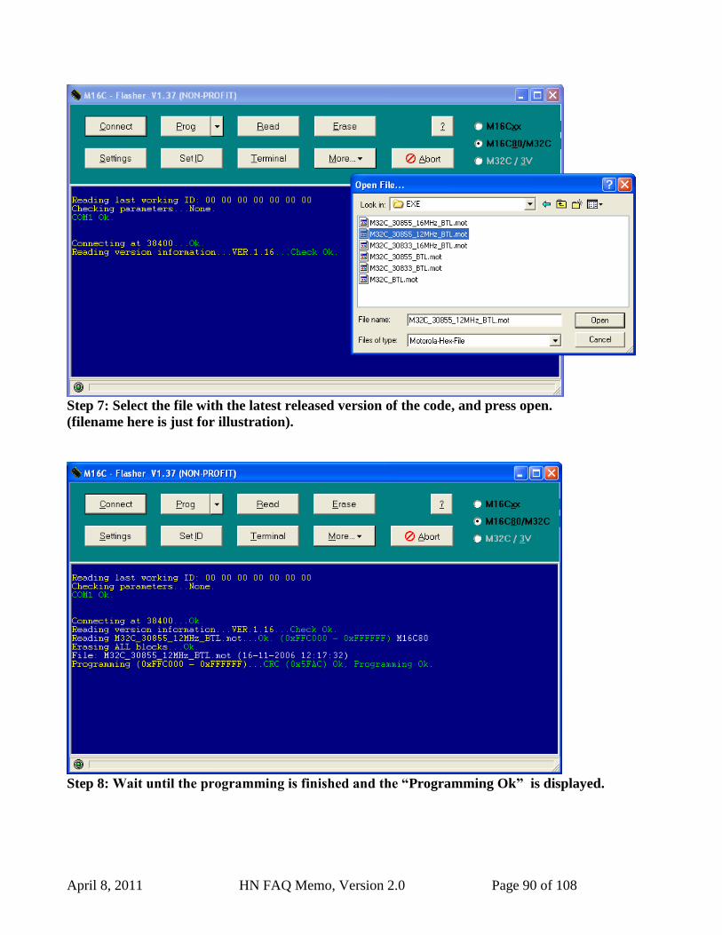
April 8, 2011 HN FAQ Memo, Version 2.0 Page 90 of 108
Step 7: Select the file with the latest released version of the code, and press open.
(filename here is just for illustration).
Step 8: Wait until the programming is finished and the “Programming Ok” is displayed.
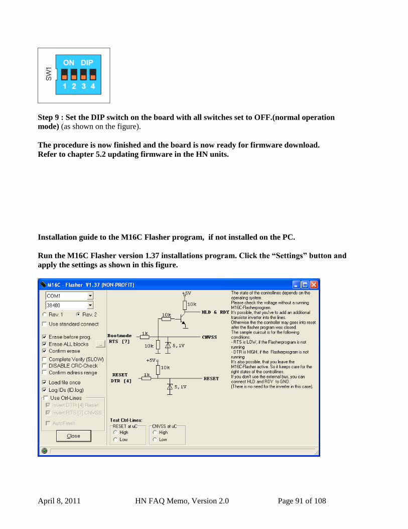
April 8, 2011 HN FAQ Memo, Version 2.0 Page 91 of 108
Step 9 : Set the DIP switch on the board with all switches set to OFF.(normal operation
mode) (as shown on the figure).
The procedure is now finished and the board is now ready for firmware download.
Refer to chapter 5.2 updating firmware in the HN units.
Installation guide to the M16C Flasher program, if not installed on the PC.
Run the M16C Flasher version 1.37 installations program. Click the “Settings” button and
apply the settings as shown in this figure.
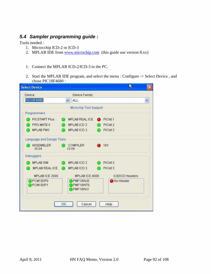
April 8, 2011 HN FAQ Memo, Version 2.0 Page 92 of 108
5.4 Sampler programming guide :
Tools needed :
1. Microcchip ICD-2 or ICD-3
2. MPLAB IDE from www.microchip.com (this guide use version 8.xx)
1. Connect the MPLAB ICD-2/ICD-3 to the PC.
2. Start the MPLAB IDE program, and select the menu : Configure -> Select Device , and
chose PIC18F4680 :
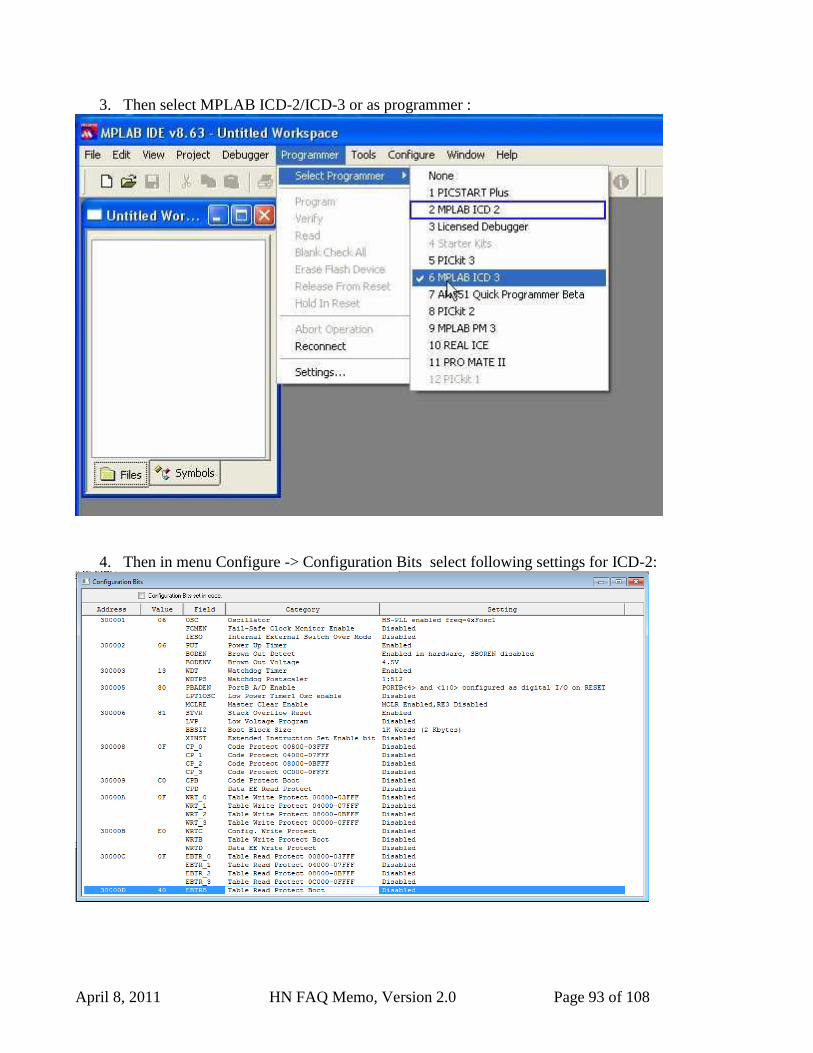
April 8, 2011 HN FAQ Memo, Version 2.0 Page 93 of 108
3. Then select MPLAB ICD-2/ICD-3 or as programmer :
4. Then in menu Configure -> Configuration Bits select following settings for ICD-2:
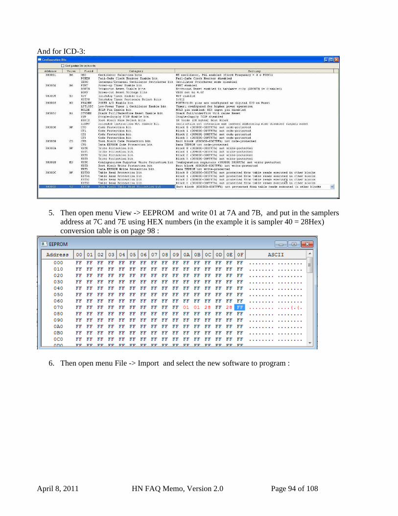
April 8, 2011 HN FAQ Memo, Version 2.0 Page 94 of 108
And for ICD-3:
5. Then open menu View -> EEPROM and write 01 at 7A and 7B, and put in the samplers
address at 7C and 7E using HEX numbers (in the example it is sampler 40 = 28Hex)
conversion table is on page 98 :
6. Then open menu File -> Import and select the new software to program :
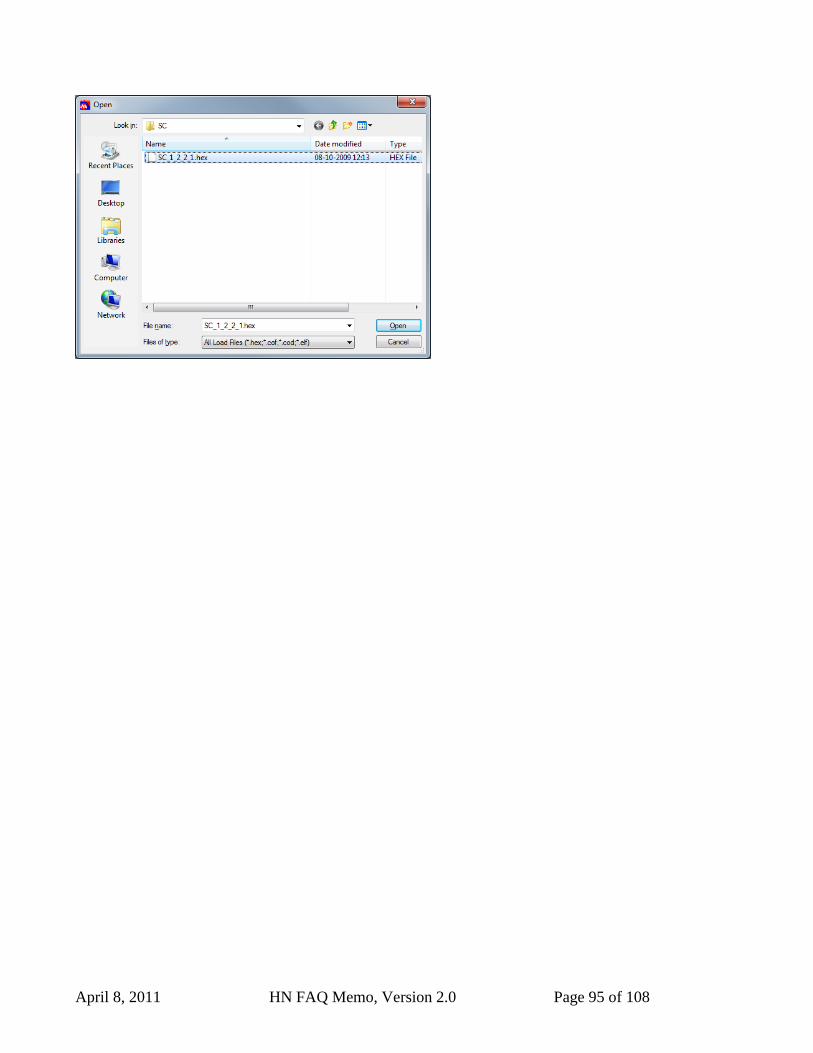
April 8, 2011 HN FAQ Memo, Version 2.0 Page 95 of 108
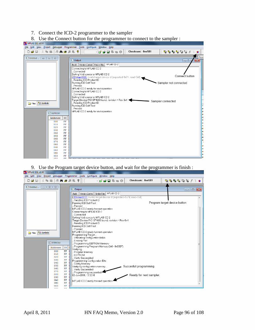
April 8, 2011 HN FAQ Memo, Version 2.0 Page 96 of 108
7. Connect the ICD-2 programmer to the sampler
8. Use the Connect button for the programmer to connect to the sampler :
9. Use the Program target device button, and wait for the programmer is finish :
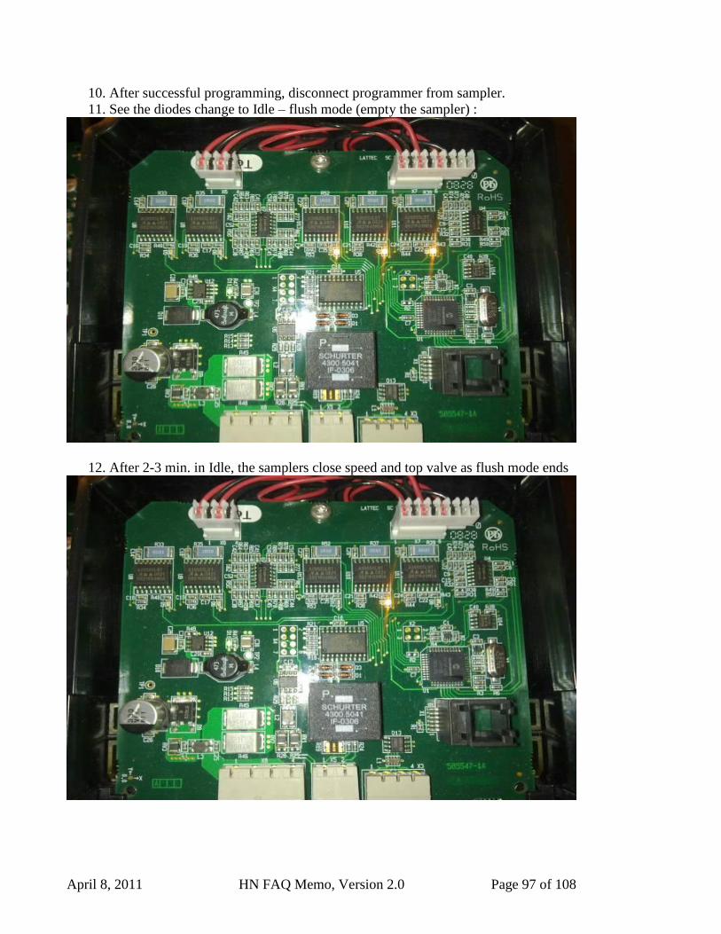
April 8, 2011 HN FAQ Memo, Version 2.0 Page 97 of 108
10. After successful programming, disconnect programmer from sampler.
11. See the diodes change to Idle – flush mode (empty the sampler) :
12. After 2-3 min. in Idle, the samplers close speed and top valve as flush mode ends
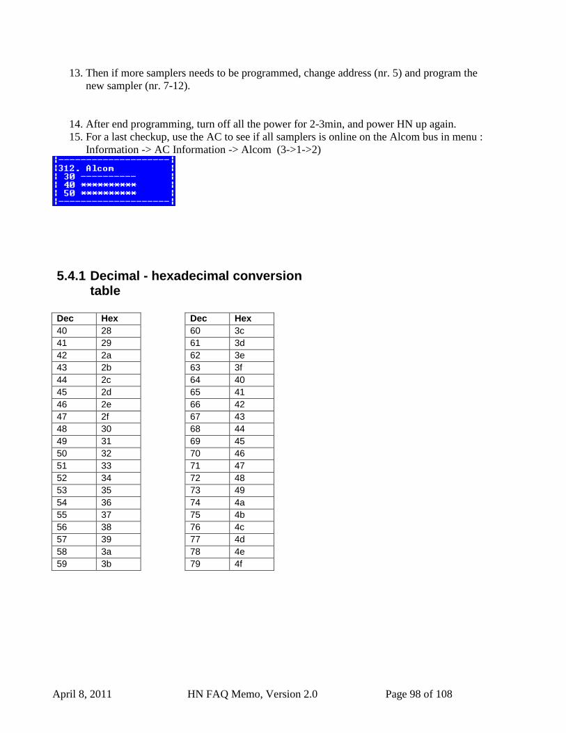
April 8, 2011 HN FAQ Memo, Version 2.0 Page 98 of 108
13. Then if more samplers needs to be programmed, change address (nr. 5) and program the
new sampler (nr. 7-12).
14. After end programming, turn off all the power for 2-3min, and power HN up again.
15. For a last checkup, use the AC to see if all samplers is online on the Alcom bus in menu :
Information -> AC Information -> Alcom (3->1->2)
5.4.1 Decimal - hexadecimal conversion table
Dec Hex Dec Hex
40 28 60 3c
41 29 61 3d
42 2a 62 3e
43 2b 63 3f
44 2c 64 40
45 2d 65 41
46 2e 66 42
47 2f 67 43
48 30 68 44
49 31 69 45
50 32 70 46
51 33 71 47
52 34 72 48
53 35 73 49
54 36 74 4a
55 37 75 4b
56 38 76 4c
57 39 77 4d
58 3a 78 4e
59 3b 79 4f

April 8, 2011 HN FAQ Memo, Version 2.0 Page 99 of 108
5.5 Updating FPGA software on HN2 AI
Needed software and tools :
USB-Blaster from Van Tool Kit.
Quartus II Programmer Version 10.1 SP 1 from Altera.
Software can be downloaded from :
https://www.altera.com/download/programming/quartus2/pq2-index.jsp
WARNING : The USB Blaster must be disconnected from the USB
cable when connected and disconnected to AI, else there is high
change for burning the board.
First Time use :
1. Install software.
2. Inset USB-Blaster to USB port, and install driver (Driver files is where the program is
installed).
3. Remove USB Cable from USB Blaster.
Programming :
1. Start Altera Programmer software.
4. Chose ”Active Serial Programming” Mode. (Figur 1)
5. Chose ”USB-Blaster” In the Hardware Setup Menu (Figur 2)
6. Chose ”Change File” and select the software to be programmed (Figur 1)
7. Select the 3 flags : Program / Verify / Blank Check.
8. Connect the USB-Blaster in AI (WARNING – mount whiteout USB Cable first).(Figur
3)
9. Plug-in USB Cable to USB-Blaster, and then the PC. (Figur 4)
10. Press ”Start”. (Figur 1)
11. When AI startup again, and Progress bar is 100% the FPGA is programmed.
12. Remove USB Cable first.
13. Disconnect the USB-Blaster.
14. You are done.
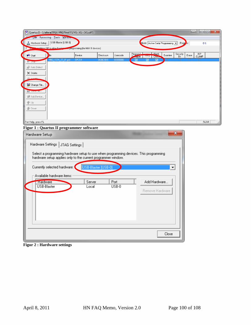
April 8, 2011 HN FAQ Memo, Version 2.0 Page 100 of 108
Figur 1 : Quartus II programmer software
Figur 2 : Hardware settings
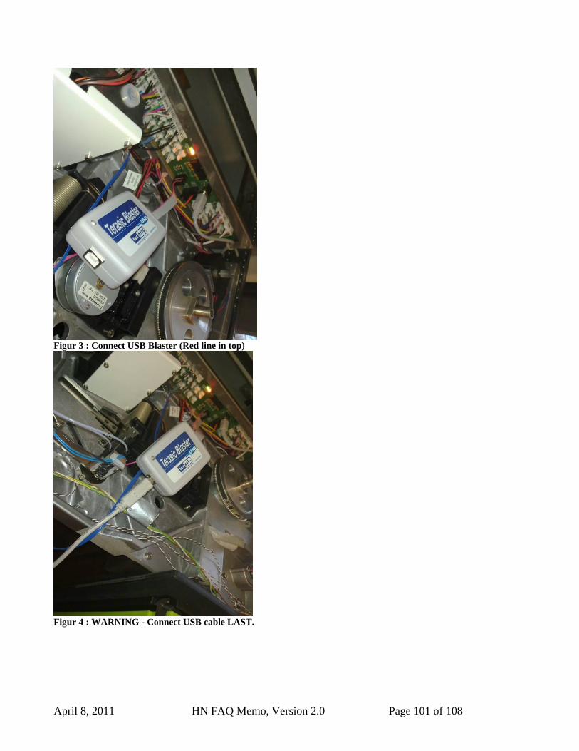
April 8, 2011 HN FAQ Memo, Version 2.0 Page 101 of 108
Figur 3 : Connect USB Blaster (Red line in top)
Figur 4 : WARNING - Connect USB cable LAST.
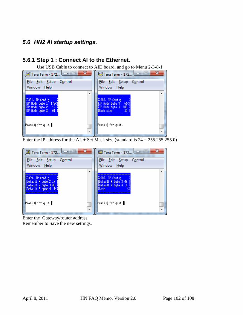
April 8, 2011 HN FAQ Memo, Version 2.0 Page 102 of 108
5.6 HN2 AI startup settings.
5.6.1 Step 1 : Connect AI to the Ethernet.
Use USB Cable to connect to AID board, and go to Menu 2-3-8-1
Enter the IP address for the AI. + Set Mask size (standard is 24 = 255.255.255.0)
Enter the Gateway/router address.
Remember to Save the new settings.
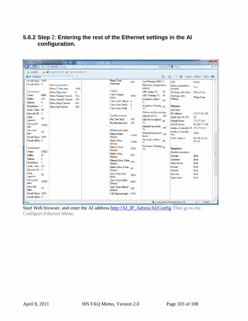
April 8, 2011 HN FAQ Memo, Version 2.0 Page 103 of 108
5.6.2 Step 2: Entering the rest of the Ethernet settings in the AI configuration.
Start Web browser, and enter the AI address http://AI_IP_Adress/AI/Config Then go to the
Configure Ethernet Menu.
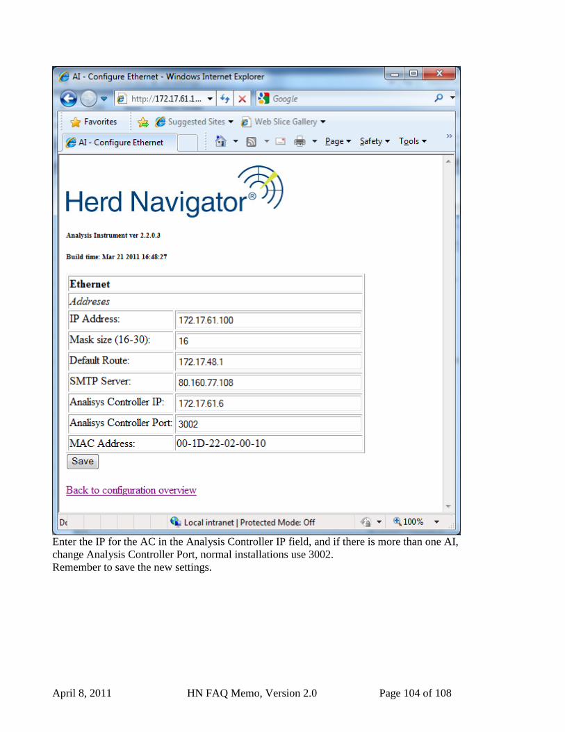
April 8, 2011 HN FAQ Memo, Version 2.0 Page 104 of 108
Enter the IP for the AC in the Analysis Controller IP field, and if there is more than one AI,
change Analysis Controller Port, normal installations use 3002.
Remember to save the new settings.
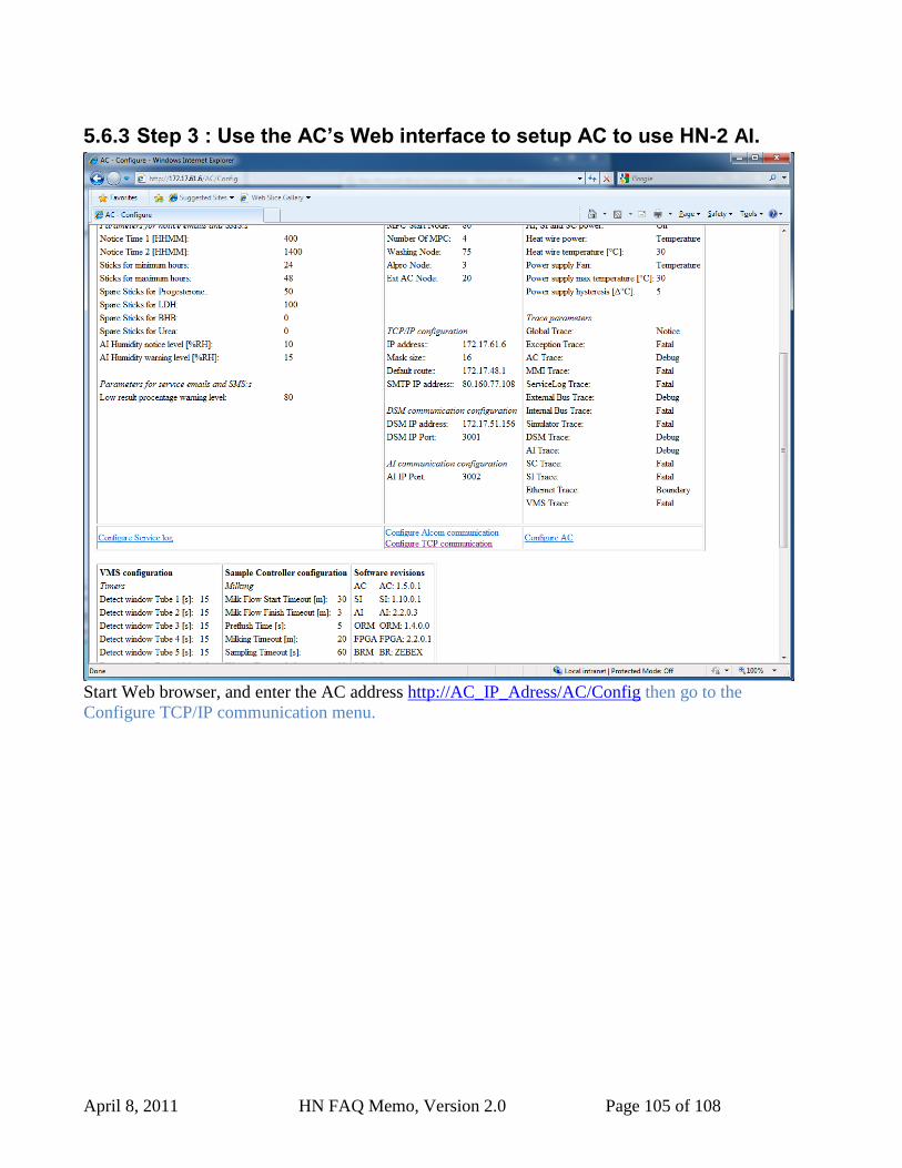
April 8, 2011 HN FAQ Memo, Version 2.0 Page 105 of 108
5.6.3 Step 3 : Use the AC’s Web interface to setup AC to use HN-2 AI.
Start Web browser, and enter the AC address http://AC_IP_Adress/AC/Config then go to the
Configure TCP/IP communication menu.
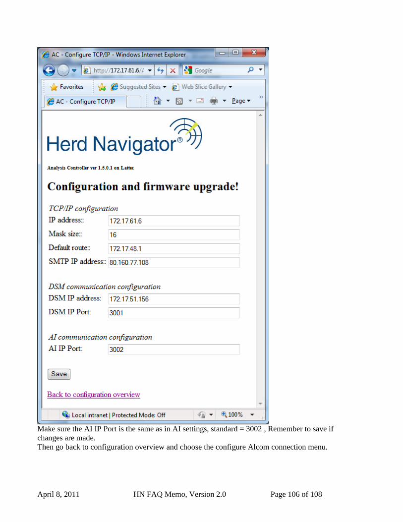
April 8, 2011 HN FAQ Memo, Version 2.0 Page 106 of 108
Make sure the AI IP Port is the same as in AI settings, standard = 3002 , Remember to save if
changes are made.
Then go back to configuration overview and choose the configure Alcom connection menu.
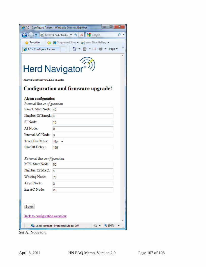
April 8, 2011 HN FAQ Memo, Version 2.0 Page 107 of 108
Set AI Node to 0

April 8, 2011 HN FAQ Memo, Version 2.0 Page 108 of 108
5.6.4 Step 4 : Setup the Alcom address for the AI in Sample Intake to same address as the AC.
In Menu 2-5-2 Change AI node from 19 to 3