Embed Size (px)
Citation preview
HMXHMX
Perfect high temperature oxidation resistance:
After oxidation at 1100 ° C, HMX series cutter coating only has a very thin oxide layer, while the similar products of Company A has completely oxidized.
A companyHMX series
Excellent coating processing technology, more closely combined with substrate
oxide
Latt ice heterogeneous coat ing added with special elements, with high hardness and excellent high temperature oxidation resistance, more suitable for high hardness materials and high speed machining
Orange red coating allows for better wear observation.
unique cut ter st ructure, proper ly designed chipbreaker, for outstanding cutting performance.
Special after treatment greatly reduces friction, for smoother chip evacuation and superior surface quality.
Lattice heterogeneous coating
New technology
Breakthrough upgrading
seriesend mills for high-hardness steel machining
B 326
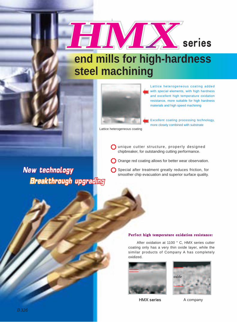
tool: HMX-4EL-D8.0milling method: end millingworkpiece material: quenched steel(HRC65)cutting speed: 100m/minfeed per revolution: 0.15mm/rdepth of cut: 0.3mmcutting width: 5mmcooling system: air cooling
tool: HMX-4E-D10.0workpiece material: SKD11(62HRC)cutting speed: 100m/minfeed per tooth: 0.2mm/raxial depth of cut: ap=10mmradial depth of cut: ae=0.3mmcooling system: air cooling
A company B companyHMX series
wear comparison after machining 60min
peripheral edges wear curves
Longer tool life
length of cutting(m)
we
ar
valu
e(
mm
)
00
0.05
0.1
0.15
0.2
0.25
20 40 60 80 100 120
HMX-4E-D10.0A companyB company
high machining efficient
1 0 0 % i m p r o v e m e n t o f m a c h i n i n g e f f i c i e n t o n H M X t h a n o t h e r s !
tool: HMX-4R-D6.0R1.0machininig parts: cavity machining
(30mm×30mm×10mm)workpiece material: quenched steel(HRC55)cutting speed: 200m/minfeed per revolution: 0.2mm/rcutting width: 0.3mmcutting depth: 5mmcooling system: air cooling
Good machining quality
tool: HMX-2B-R3.0workpiece material: SKD11(HRC62)
cutting speed : 200m/minfeed per revolution: 0.2mm/rcutting width: 0.2mmcutting depth: 0.3mmcooling system: air cooling
time comparison for complete one cavity
surface roughness curves of machined surface
peripheral edge rake face
normal wear
severe wear
edge chipping
wear condition
HMX
A company
B company
wear comparison after machining 40min
A company
B company
HMX
0 10 20 30 40 50 60 70time(min)
80
30
70
65
HMX-2B-R3.0A companyB company
length of cutting(m)
surf
ace
ro
ug
hn
ess
(m
m)
00
0.5
11.5
2
2.5
3
5 10 15 20 25 30 35
HMXseries end mills for high-hardness steel machining
B 327
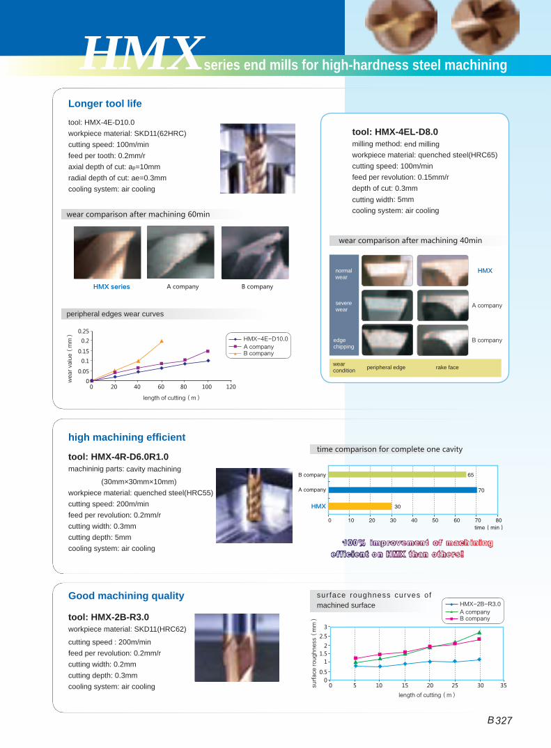
Ordering numberBasic dimension(mm) Number of
teethZ
Geometry StockD d H L
HMX-2E-D1.0S 1.0 4 3 50 2 Picture 1 ●
HMX-2E-D1.5S 1.5 4 4 50 2 Picture 1 ●
HMX-2E-D2.0S 2.0 4 6 50 2 Picture 1 ●
HMX-2E-D2.5S 2.5 4 8 50 2 Picture 1 ●
HMX-2E-D3.0S 3.0 4 8 50 2 Picture 1 ●
HMX-2E-D4.0S 4.0 4 11 50 2 Picture 2 ●
HMX-2E-D1.0 1.0 6 3 50 2 Picture 1 ●
HMX-2E-D1.5 1.5 6 4 50 2 Picture 1 ●
HMX-2E-D2.0 2.0 6 6 50 2 Picture 1 ●
HMX-2E-D2.5 2.5 6 8 50 2 Picture 1 ●
HMX-2E-D3.0 3.0 6 8 50 2 Picture 1 ●
HMX-2E-D3.5 3.5 6 10 50 2 Picture 1 ●
HMX-2E-D4.0 4.0 6 11 50 2 Picture 1 ●
HMX-2E-D4.5 4.5 6 11 50 2 Picture 1 ●
HMX-2E-D5.0 5.0 6 13 50 2 Picture 1 ●
HMX-2E-D5.5 5.5 6 16 50 2 Picture 1 ●
HMX-2E-D6.0 6.0 6 16 50 2 Picture 2 ●
HMX-2E-D7.0 7.0 8 20 60 2 Picture 1 ●
HMX-2E-D8.0 8.0 8 20 60 2 Picture 2 ●
HMX-2E-D9.0 9.0 10 22 75 2 Picture 1 ●
HMX-2E-D10.0 10.0 10 25 75 2 Picture 2 ●
HMX-2E-D11.0 11.0 12 26 75 2 Picture 1 ●
HMX-2E-D12.0 12.0 12 30 75 2 Picture 2 ●
HMX-2E-D14.0 14.0 14 32 100 2 Picture 2 ●
HMX-2E-D16.0 16.0 16 45 100 2 Picture 2 ●
HMX-2E-D18.0 18.0 18 45 100 2 Picture 2 ●
HMX-2E-D20.0 20.0 20 45 100 2 Picture 2 ●
● Stock available ○ Make-to-order
Workpiece material
Carbon steel Alloy steel
Pre-hardened steel、Hardened steel Stainless steel
Cast iron, Nodular cast iron
Copper alloy
Aluminum alloy
Titanium alloy
Heat resistant
alloy~40HRC ~50HRC ~55HRC ~68HRC
○ ◎ ◎ ○
35o D≤12 0~-0.02012<D 0~-0.030D
L
D
H
d
L
d
H
D
10°Picture 1
Picture 2● For slot milling. ● Very suitable for high speed cutting and dry cutting.
HMX-2E Corner protection
Side face Step shoulder Straight slot
Code key Cutting parametersGraphics category and identificationB213 B410B214
Applicable workpiece material table ◎Very suitable ○Suitable
2-flute flattened end mills with straight shank
TiAIXNNaNo
Coated
B
B 328
Solid Carbide End MillsMILLINGMILLING
Indexable m
illing toolsSolid carbide
end mills
HMX series
HMX series for machining high hardness steel
Workpiece material
Carbon steel Alloy steel
Pre-hardened steel、Hardened steel Stainless steel
Cast iron, Nodular cast iron
Copper alloy
Aluminum alloy
Titanium alloy
Heat resistant
alloy~40HRC ~50HRC ~55HRC ~68HRC
○ ◎ ◎ ○
Ordering numberBasic dimension(mm) Number of
teethZ
StockD d H M d1 L
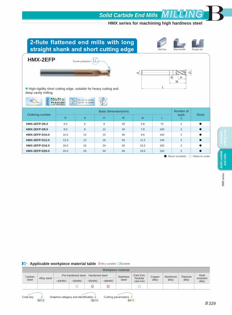
HMX-2EFP-D6.0 6.0 6 9 30 5.8 75 2 ●
HMX-2EFP-D8.0 8.0 8 12 40 7.8 100 2 ●
HMX-2EFP-D10.0 10.0 10 15 50 9.6 100 2 ●
HMX-2EFP-D12.0 12.0 12 18 50 11.5 100 2 ●
HMX-2EFP-D16.0 16.0 16 24 50 15.5 150 2 ●
HMX-2EFP-D20.0 20.0 20 30 60 19.5 150 2 ●
● Stock available ○ Make-to-order
35o D≤12 0~-0.02012<D 0~-0.030D
● High-rigidity short cutting edge, suitable for heavy cutting and deep cavity milling.
HMX-2EFP Corner protection
Side face Step shoulder Straight slot
Applicable workpiece material table ◎Very suitable ○Suitable
Code key Cutting parametersGraphics category and identificationB213 B411B214
2-flute flattened end mills with long straight shank and short cutting edge
TiAIXNNaNo
Coated
B
B 329
Solid Carbide End Mills MILLINGMILLING
Inde
xabl
e m
illin
g to
ols
Solid
car
bide
en
d m
ills
HMX
serie
s
HMX series for machining high hardness steel
Ordering numberBasic dimension(mm) Number of
teethZ
Geometry StockD d H L
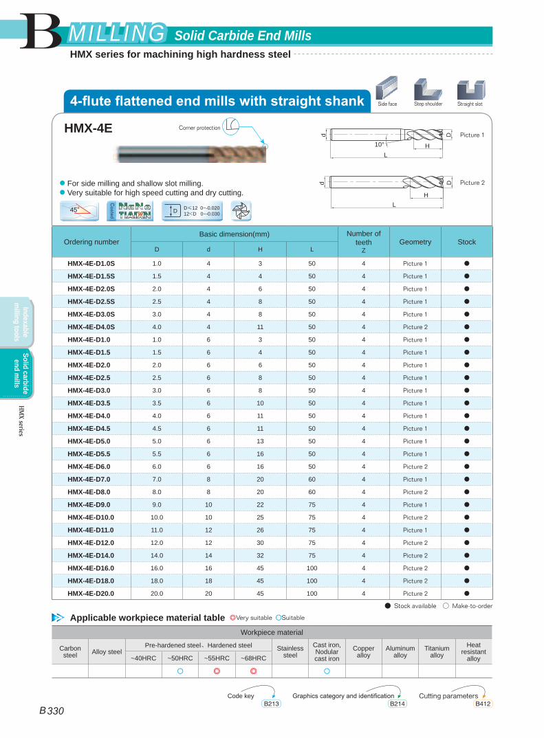
HMX-4E-D1.0S 1.0 4 3 50 4 Picture 1 ●
HMX-4E-D1.5S 1.5 4 4 50 4 Picture 1 ●
HMX-4E-D2.0S 2.0 4 6 50 4 Picture 1 ●
HMX-4E-D2.5S 2.5 4 8 50 4 Picture 1 ●
HMX-4E-D3.0S 3.0 4 8 50 4 Picture 1 ●
HMX-4E-D4.0S 4.0 4 11 50 4 Picture 2 ●
HMX-4E-D1.0 1.0 6 3 50 4 Picture 1 ●
HMX-4E-D1.5 1.5 6 4 50 4 Picture 1 ●
HMX-4E-D2.0 2.0 6 6 50 4 Picture 1 ●
HMX-4E-D2.5 2.5 6 8 50 4 Picture 1 ●
HMX-4E-D3.0 3.0 6 8 50 4 Picture 1 ●
HMX-4E-D3.5 3.5 6 10 50 4 Picture 1 ●
HMX-4E-D4.0 4.0 6 11 50 4 Picture 1 ●
HMX-4E-D4.5 4.5 6 11 50 4 Picture 1 ●
HMX-4E-D5.0 5.0 6 13 50 4 Picture 1 ●
HMX-4E-D5.5 5.5 6 16 50 4 Picture 1 ●
HMX-4E-D6.0 6.0 6 16 50 4 Picture 2 ●
HMX-4E-D7.0 7.0 8 20 60 4 Picture 1 ●
HMX-4E-D8.0 8.0 8 20 60 4 Picture 2 ●
HMX-4E-D9.0 9.0 10 22 75 4 Picture 1 ●
HMX-4E-D10.0 10.0 10 25 75 4 Picture 2 ●
HMX-4E-D11.0 11.0 12 26 75 4 Picture 1 ●
HMX-4E-D12.0 12.0 12 30 75 4 Picture 2 ●
HMX-4E-D14.0 14.0 14 32 75 4 Picture 2 ●
HMX-4E-D16.0 16.0 16 45 100 4 Picture 2 ●
HMX-4E-D18.0 18.0 18 45 100 4 Picture 2 ●
HMX-4E-D20.0 20.0 20 45 100 4 Picture 2 ●
● Stock available ○ Make-to-order
45o D≤12 0~-0.02012<D 0~-0.030D
L
D
H10°
d
LH
Dd
Picture 1
Picture 2● For side milling and shallow slot milling. ● Very suitable for high speed cutting and dry cutting.
Workpiece material
Carbon steel Alloy steel
Pre-hardened steel、Hardened steel Stainless steel
Cast iron, Nodular cast iron
Copper alloy
Aluminum alloy
Titanium alloy
Heat resistant
alloy~40HRC ~50HRC ~55HRC ~68HRC
○ ◎ ◎ ○
HMX-4E Corner protection
Side face Step shoulder Straight slot
Applicable workpiece material table ◎Very suitable ○Suitable
Code key Cutting parametersGraphics category and identificationB213 B412B214
4-flute flattened end mills with straight shank
TiAIXNNaNo
Coated
B
B 330
Solid Carbide End MillsMILLINGMILLING
Indexable m
illing toolsSolid carbide
end mills
HMX series
HMX series for machining high hardness steel
Ordering numberBasic dimension(mm) Number of
teethZ
Geometry StockD d H L
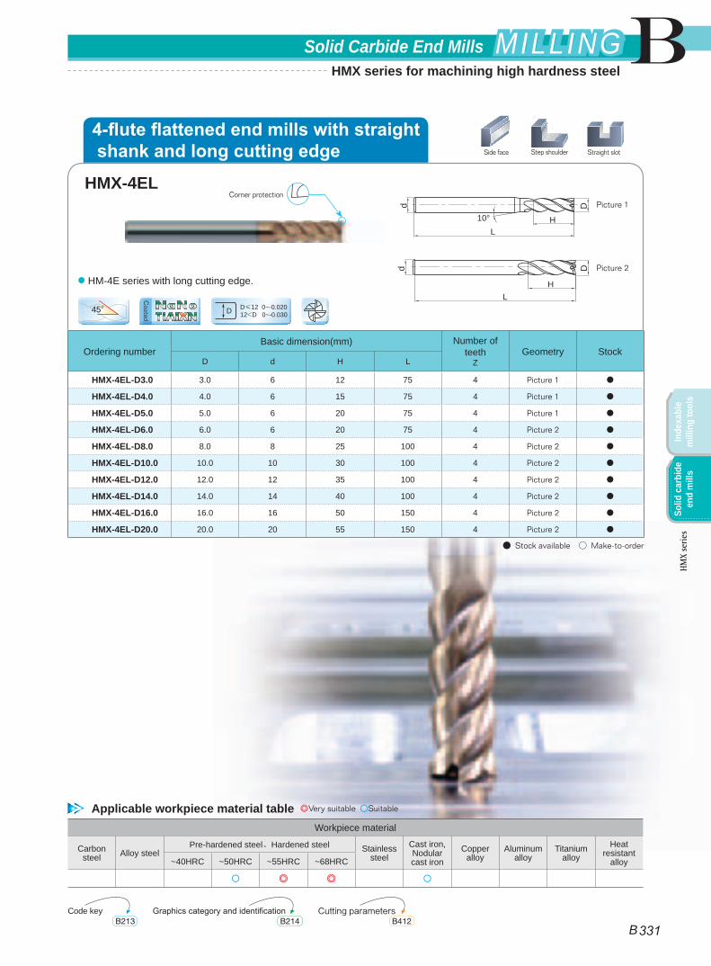
HMX-4EL-D3.0 3.0 6 12 75 4 Picture 1 ●
HMX-4EL-D4.0 4.0 6 15 75 4 Picture 1 ●
HMX-4EL-D5.0 5.0 6 20 75 4 Picture 1 ●
HMX-4EL-D6.0 6.0 6 20 75 4 Picture 2 ●
HMX-4EL-D8.0 8.0 8 25 100 4 Picture 2 ●
HMX-4EL-D10.0 10.0 10 30 100 4 Picture 2 ●
HMX-4EL-D12.0 12.0 12 35 100 4 Picture 2 ●
HMX-4EL-D14.0 14.0 14 40 100 4 Picture 2 ●
HMX-4EL-D16.0 16.0 16 50 150 4 Picture 2 ●
HMX-4EL-D20.0 20.0 20 55 150 4 Picture 2 ●
● Stock available ○ Make-to-order
45o D≤12 0~-0.02012<D 0~-0.030D
L
D
H10°
d
LH
Dd
Picture 1
Picture 2● HM-4E series with long cutting edge.
Workpiece material
Carbon steel Alloy steel
Pre-hardened steel、Hardened steel Stainless steel
Cast iron, Nodular cast iron
Copper alloy
Aluminum alloy
Titanium alloy
Heat resistant
alloy~40HRC ~50HRC ~55HRC ~68HRC
○ ◎ ◎ ○
HMX-4EL
Side face Step shoulder Straight slot
Applicable workpiece material table ◎Very suitable ○Suitable
Code key Cutting parametersGraphics category and identificationB213 B412B214
4-flute flattened end mills with straight shank and long cutting edge
Corner protection
TiAIXNNaNo
Coated
B
B 331
Solid Carbide End Mills MILLINGMILLING
Inde
xabl
e m
illin
g to
ols
Solid
car
bide
en
d m
ills
HMX
serie
s
HMX series for machining high hardness steel
Ordering numberBasic dimension(mm) Number of
teethZ
StockD d H M d1 L
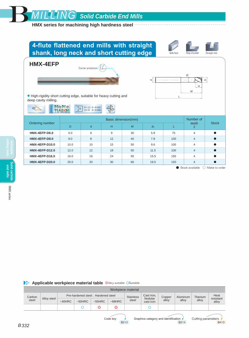
HMX-4EFP-D6.0 6.0 6 9 30 5.8 75 4 ●
HMX-4EFP-D8.0 8.0 8 12 40 7.8 100 4 ●
HMX-4EFP-D10.0 10.0 10 15 50 9.6 100 4 ●
HMX-4EFP-D12.0 12.0 12 18 50 11.5 100 4 ●
HMX-4EFP-D16.0 16.0 16 24 50 15.5 150 4 ●
HMX-4EFP-D20.0 20.0 20 30 60 19.5 150 4 ●
● Stock available ○ Make-to-order
45o D≤12 0~-0.02012<D 0~-0.030D
● High-rigidity short cutting edge, suitable for heavy cutting and deep cavity milling.
Workpiece material
Carbon steel Alloy steel
Pre-hardened steel、Hardened steel Stainless steel
Cast iron, Nodular cast iron
Copper alloy
Aluminum alloy
Titanium alloy
Heat resistant
alloy~40HRC ~50HRC ~55HRC ~68HRC
○ ◎ ◎ ○
HMX-4EFP
d
L
d1
H
M
D
Corner protection
Side face Step shoulder Straight slot
Applicable workpiece material table ◎Very suitable ○Suitable
Code key Cutting parametersGraphics category and identificationB213 B413B214
4-flute flattened end mills with straight shank, long neck and short cutting edge
TiAIXNNaNo
Coated
B
B 332
Solid Carbide End MillsMILLINGMILLING
Indexable m
illing toolsSolid carbide
end mills
HMX series
HMX series for machining high hardness steel
Ordering numberBasic dimension(mm) Number of teeth
Z StockD d H L
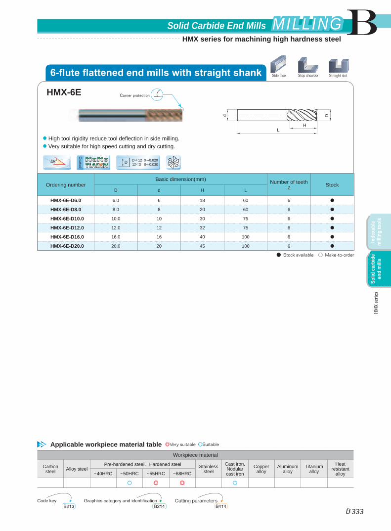
HMX-6E-D6.0 6.0 6 18 60 6 ●
HMX-6E-D8.0 8.0 8 20 60 6 ●
HMX-6E-D10.0 10.0 10 30 75 6 ●
HMX-6E-D12.0 12.0 12 32 75 6 ●
HMX-6E-D16.0 16.0 16 40 100 6 ●
HMX-6E-D20.0 20.0 20 45 100 6 ●
● Stock available ○ Make-to-order
45o D≤12 0~-0.02012<D 0~-0.030D
L
D
H
d
● High tool rigidity reduce tool deflection in side milling.● Very suitable for high speed cutting and dry cutting.
Workpiece material
Carbon steel Alloy steel
Pre-hardened steel、Hardened steel Stainless steel
Cast iron, Nodular cast iron
Copper alloy
Aluminum alloy
Titanium alloy
Heat resistant
alloy~40HRC ~50HRC ~55HRC ~68HRC
○ ◎ ◎ ○
HMX-6E Corner protection
Side face Step shoulder Straight slot
Applicable workpiece material table ◎Very suitable ○Suitable
Code key Cutting parametersGraphics category and identificationB213 B414B214
6-flute flattened end mills with straight shank
TiAIXNNaNo
Coated
B
B 333
Solid Carbide End Mills MILLINGMILLING
Inde
xabl
e m
illin
g to
ols
Solid
car
bide
en
d m
ills
HMX
serie
s
HMX series for machining high hardness steel
Ordering numberBasic dimension(mm) Number of teeth
Z StockD d H L
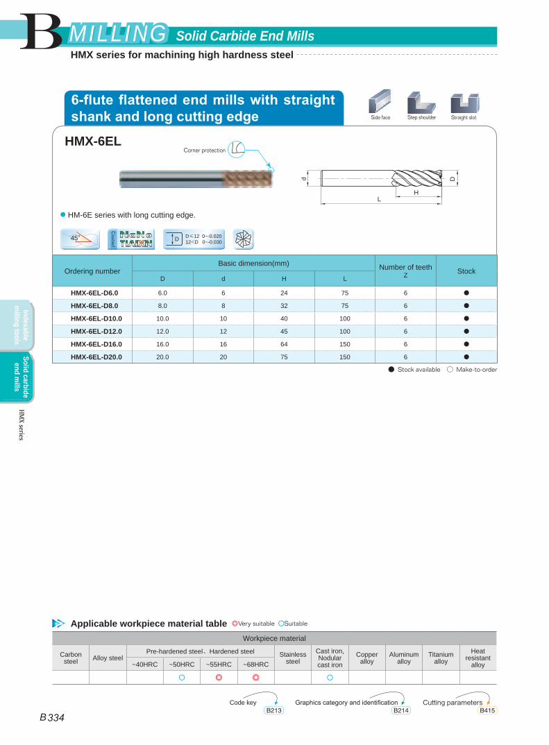
HMX-6EL-D6.0 6.0 6 24 75 6 ●
HMX-6EL-D8.0 8.0 8 32 75 6 ●
HMX-6EL-D10.0 10.0 10 40 100 6 ●
HMX-6EL-D12.0 12.0 12 45 100 6 ●
HMX-6EL-D16.0 16.0 16 64 150 6 ●
HMX-6EL-D20.0 20.0 20 75 150 6 ●
● Stock available ○ Make-to-order
45o D≤12 0~-0.02012<D 0~-0.030D
L
D
H
d
● HM-6E series with long cutting edge.
Workpiece material
Carbon steel Alloy steel
Pre-hardened steel、Hardened steel Stainless steel
Cast iron, Nodular cast iron
Copper alloy
Aluminum alloy
Titanium alloy
Heat resistant
alloy~40HRC ~50HRC ~55HRC ~68HRC
○ ◎ ◎ ○
HMX-6ELCorner protection
Side face Step shoulder Straight slot
Applicable workpiece material table ◎Very suitable ○Suitable
Code key Cutting parametersGraphics category and identificationB213 B415B214
6-flute flattened end mills with straight shank and long cutting edge
TiAIXNNaNo
Coated
B
B 334
Solid Carbide End MillsMILLINGMILLING
Indexable m
illing toolsSolid carbide
end mills
HMX series
HMX series for machining high hardness steel
L
D
H
d
d1 M10°
Workpiece material
Carbon steel Alloy steel
Pre-hardened steel、Hardened steel Stainless steel
Cast iron, Nodular cast iron
Copper alloy
Aluminum alloy
Titanium alloy
Heat resistant
alloy~40HRC ~50HRC ~55HRC ~68HRC
○ ◎ ◎ ○
Ordering numberBasic dimension(mm) Number of
teethZ
StockD d H M d1 L
HMX-2EP-D0.5-M04 0.5 4 0.7 4 0.45 50 2 ●
HMX-2EP-D0.5-M06 0.5 4 0.7 6 0.45 50 2 ●
HMX-2EP-D0.5-M08 0.5 4 0.7 8 0.45 50 2 ●
HMX-2EP-D0.8-M04 0.8 4 1.2 4 0.75 50 2 ●
HMX-2EP-D0.8-M06 0.8 4 1.2 6 0.75 50 2 ●
HMX-2EP-D0.8-M08 0.8 4 1.2 8 0.75 50 2 ●
HMX-2EP-D0.8-M10 0.8 4 1.2 10 0.75 50 2 ●
HMX-2EP-D1.0-M04 1.0 4 1.5 4 0.95 50 2 ●
HMX-2EP-D1.0-M06 1.0 4 1.5 6 0.95 50 2 ●
HMX-2EP-D1.0-M08 1.0 4 1.5 8 0.95 50 2 ●
HMX-2EP-D1.0-M10 1.0 4 1.5 10 0.95 50 2 ●
HMX-2EP-D1.0-M12 1.0 4 1.5 12 0.95 50 2 ●
HMX-2EP-D1.0-M14 1.0 4 1.5 14 0.95 50 2 ●
HMX-2EP-D1.2-M06 1.2 4 1.8 6 1.15 50 2 ●
HMX-2EP-D1.2-M08 1.2 4 1.8 8 1.15 50 2 ●
HMX-2EP-D1.2-M10 1.2 4 1.8 10 1.15 50 2 ●
HMX-2EP-D1.2-M12 1.2 4 1.8 12 1.15 50 2 ●
HMX-2EP-D1.5-M06 1.5 4 2.3 6 1.45 50 2 ●
HMX-2EP-D1.5-M08 1.5 4 2.3 8 1.45 50 2 ●
HMX-2EP-D1.5-M10 1.5 4 2.3 10 1.45 50 2 ●
HMX-2EP-D1.5-M12 1.5 4 2.3 12 1.45 50 2 ●
HMX-2EP-D1.5-M14 1.5 4 2.3 14 1.45 50 2 ●
HMX-2EP-D2.0-M06 2.0 4 3.0 6 1.95 50 2 ●
HMX-2EP-D2.0-M08 2.0 4 3.0 8 1.95 50 2 ●
HMX-2EP-D2.0-M10 2.0 4 3.0 10 1.95 50 2 ●
HMX-2EP-D2.0-M12 2.0 4 3.0 12 1.95 50 2 ●
● Stock available ○ Make-to-order
35o0~-0.015D
D<1mm 1mm≤D
Deep flattened slot
● Suitable for narrow slot milling or milling of fine parts that could generate interference.
Applicable workpiece material table ◎Very suitable ○Suitable
Code key Cutting parametersGraphics category and identificationB213 B416-B417B214
2-flute flattened end mills with straight shank, long neck and short cutting edge
HMX-2EP
TiAIXNNaNo
Coated
B
B 335
Solid Carbide End Mills MILLINGMILLING
Inde
xabl
e m
illin
g to
ols
Solid
car
bide
en
d m
ills
HMX
serie
s
HMX series for machining high hardness steel
Ordering numberBasic dimension(mm) Number of
teethZ
StockD d H M d1 L
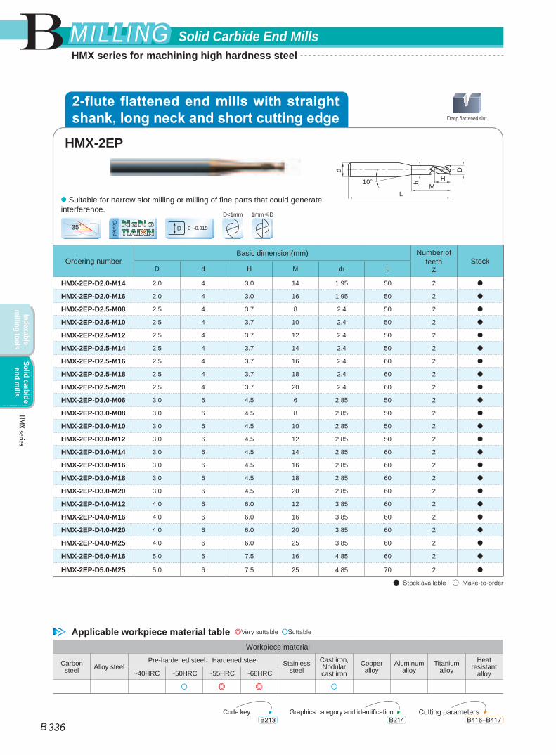
HMX-2EP-D2.0-M14 2.0 4 3.0 14 1.95 50 2 ●
HMX-2EP-D2.0-M16 2.0 4 3.0 16 1.95 50 2 ●
HMX-2EP-D2.5-M08 2.5 4 3.7 8 2.4 50 2 ●
HMX-2EP-D2.5-M10 2.5 4 3.7 10 2.4 50 2 ●
HMX-2EP-D2.5-M12 2.5 4 3.7 12 2.4 50 2 ●
HMX-2EP-D2.5-M14 2.5 4 3.7 14 2.4 50 2 ●
HMX-2EP-D2.5-M16 2.5 4 3.7 16 2.4 60 2 ●
HMX-2EP-D2.5-M18 2.5 4 3.7 18 2.4 60 2 ●
HMX-2EP-D2.5-M20 2.5 4 3.7 20 2.4 60 2 ●
HMX-2EP-D3.0-M06 3.0 6 4.5 6 2.85 50 2 ●
HMX-2EP-D3.0-M08 3.0 6 4.5 8 2.85 50 2 ●
HMX-2EP-D3.0-M10 3.0 6 4.5 10 2.85 50 2 ●
HMX-2EP-D3.0-M12 3.0 6 4.5 12 2.85 50 2 ●
HMX-2EP-D3.0-M14 3.0 6 4.5 14 2.85 60 2 ●
HMX-2EP-D3.0-M16 3.0 6 4.5 16 2.85 60 2 ●
HMX-2EP-D3.0-M18 3.0 6 4.5 18 2.85 60 2 ●
HMX-2EP-D3.0-M20 3.0 6 4.5 20 2.85 60 2 ●
HMX-2EP-D4.0-M12 4.0 6 6.0 12 3.85 60 2 ●
HMX-2EP-D4.0-M16 4.0 6 6.0 16 3.85 60 2 ●
HMX-2EP-D4.0-M20 4.0 6 6.0 20 3.85 60 2 ●
HMX-2EP-D4.0-M25 4.0 6 6.0 25 3.85 60 2 ●
HMX-2EP-D5.0-M16 5.0 6 7.5 16 4.85 60 2 ●
HMX-2EP-D5.0-M25 5.0 6 7.5 25 4.85 70 2 ●
● Stock available ○ Make-to-order
35o0~-0.015D
D<1mm 1mm≤D
L
D
H
d
d1 M10°
● Suitable for narrow slot milling or milling of fine parts that could generate interference.
Workpiece material
Carbon steel Alloy steel
Pre-hardened steel、Hardened steel Stainless steel
Cast iron, Nodular cast iron
Copper alloy
Aluminum alloy
Titanium alloy
Heat resistant
alloy~40HRC ~50HRC ~55HRC ~68HRC
○ ◎ ◎ ○
HMX-2EP
Deep flattened slot
Applicable workpiece material table ◎Very suitable ○Suitable
Code key Cutting parametersGraphics category and identificationB213 B416-B417B214
2-flute flattened end mills with straight shank, long neck and short cutting edge
TiAIXNNaNo
Coated
B
B 336
Solid Carbide End MillsMILLINGMILLING
Indexable m
illing toolsSolid carbide
end mills
HMX series
HMX series for machining high hardness steel
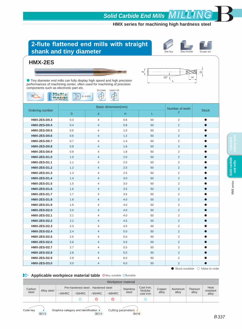
Ordering numberBasic dimension(mm) Number of teeth
Z StockD d H L
HMX-2ES-D0.3 0.3 4 0.6 50 2 ●
HMX-2ES-D0.4 0.4 4 0.8 50 2 ●
HMX-2ES-D0.5 0.5 4 1.0 50 2 ●
HMX-2ES-D0.6 0.6 4 1.2 50 2 ●
HMX-2ES-D0.7 0.7 4 1.4 50 2 ●
HMX-2ES-D0.8 0.8 4 1.6 50 2 ●
HMX-2ES-D0.9 0.9 4 1.8 50 2 ●
HMX-2ES-D1.0 1.0 4 2.0 50 2 ●
HMX-2ES-D1.1 1.1 4 2.0 50 2 ●
HMX-2ES-D1.2 1.2 4 2.5 50 2 ●
HMX-2ES-D1.3 1.3 4 2.5 50 2 ●
HMX-2ES-D1.4 1.4 4 3.0 50 2 ●
HMX-2ES-D1.5 1.5 4 3.0 50 2 ●
HMX-2ES-D1.6 1.6 4 3.5 50 2 ●
HMX-2ES-D1.7 1.7 4 3.5 50 2 ●
HMX-2ES-D1.8 1.8 4 4.0 50 2 ●
HMX-2ES-D1.9 1.9 4 4.0 50 2 ●
HMX-2ES-D2.0 2.0 4 4.0 50 2 ●
HMX-2ES-D2.1 2.1 4 4.0 50 2 ●
HMX-2ES-D2.2 2.2 4 4.5 50 2 ●
HMX-2ES-D2.3 2.3 4 4.5 50 2 ●
HMX-2ES-D2.4 2.4 4 5.0 50 2 ●
HMX-2ES-D2.5 2.5 4 5.0 50 2 ●
HMX-2ES-D2.6 2.6 4 5.0 50 2 ●
HMX-2ES-D2.7 2.7 4 5.5 50 2 ●
HMX-2ES-D2.8 2.8 4 5.5 50 2 ●
HMX-2ES-D2.9 2.9 4 6.0 50 2 ●
HMX-2ES-D3.0 3.0 4 6.0 50 2 ●
● Stock available ○ Make-to-order
35o0~-0.015D
D<1mm 1mm≤D
L
D
H
d
10°● Tiny diameter end mills can fully display high speed and high precision performances of machining center, often used for machining of precision components such as electronic part etc.
Workpiece material
Carbon steel Alloy steel
Pre-hardened steel、Hardened steel Stainless steel
Cast iron, Nodular cast iron
Copper alloy
Aluminum alloy
Titanium alloy
Heat resistant
alloy~40HRC ~50HRC ~55HRC ~68HRC
○ ◎ ◎ ○
HMX-2ES
Side face Step shoulder Straight slot
Applicable workpiece material table ◎Very suitable ○Suitable
Code key Cutting parametersGraphics category and identificationB213 B418B214
2-flute flattened end mills with straight shank and tiny diameter
TiAIXNNaNo
Coated
B
B 337
Solid Carbide End Mills MILLINGMILLING
Inde
xabl
e m
illin
g to
ols
Solid
car
bide
en
d m
ills
HMX
serie
s
HMX series for machining high hardness steel
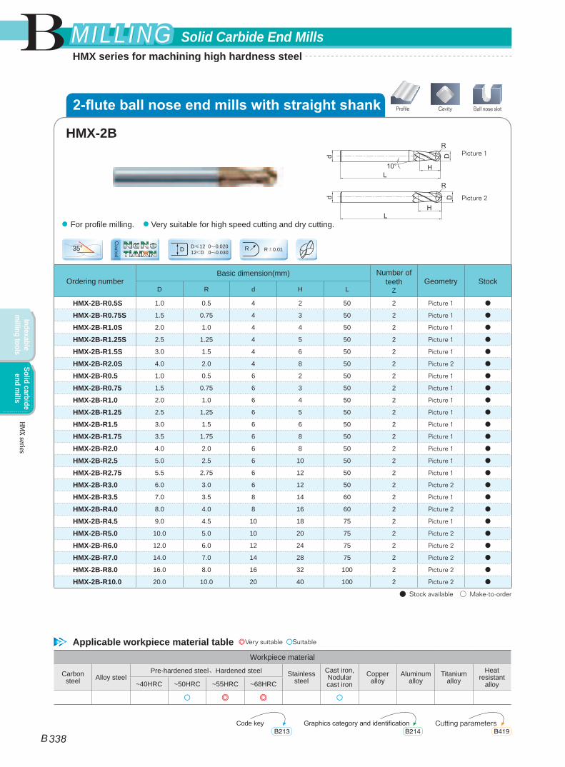
Ordering numberBasic dimension(mm) Number of
teethZ
Geometry StockD R d H L
HMX-2B-R0.5S 1.0 0.5 4 2 50 2 Picture 1 ●
HMX-2B-R0.75S 1.5 0.75 4 3 50 2 Picture 1 ●
HMX-2B-R1.0S 2.0 1.0 4 4 50 2 Picture 1 ●
HMX-2B-R1.25S 2.5 1.25 4 5 50 2 Picture 1 ●
HMX-2B-R1.5S 3.0 1.5 4 6 50 2 Picture 1 ●
HMX-2B-R2.0S 4.0 2.0 4 8 50 2 Picture 2 ●
HMX-2B-R0.5 1.0 0.5 6 2 50 2 Picture 1 ●
HMX-2B-R0.75 1.5 0.75 6 3 50 2 Picture 1 ●
HMX-2B-R1.0 2.0 1.0 6 4 50 2 Picture 1 ●
HMX-2B-R1.25 2.5 1.25 6 5 50 2 Picture 1 ●
HMX-2B-R1.5 3.0 1.5 6 6 50 2 Picture 1 ●
HMX-2B-R1.75 3.5 1.75 6 8 50 2 Picture 1 ●
HMX-2B-R2.0 4.0 2.0 6 8 50 2 Picture 1 ●
HMX-2B-R2.5 5.0 2.5 6 10 50 2 Picture 1 ●
HMX-2B-R2.75 5.5 2.75 6 12 50 2 Picture 1 ●
HMX-2B-R3.0 6.0 3.0 6 12 50 2 Picture 2 ●
HMX-2B-R3.5 7.0 3.5 8 14 60 2 Picture 1 ●
HMX-2B-R4.0 8.0 4.0 8 16 60 2 Picture 2 ●
HMX-2B-R4.5 9.0 4.5 10 18 75 2 Picture 1 ●
HMX-2B-R5.0 10.0 5.0 10 20 75 2 Picture 2 ●
HMX-2B-R6.0 12.0 6.0 12 24 75 2 Picture 2 ●
HMX-2B-R7.0 14.0 7.0 14 28 75 2 Picture 2 ●
HMX-2B-R8.0 16.0 8.0 16 32 100 2 Picture 2 ●
HMX-2B-R10.0 20.0 10.0 20 40 100 2 Picture 2 ●
● Stock available ○ Make-to-order
35o D≤12 0~-0.02012<D 0~-0.030D R±0.01R
Picture 1
Picture 2
● For profile milling. ● Very suitable for high speed cutting and dry cutting.
Workpiece material
Carbon steel Alloy steel
Pre-hardened steel、Hardened steel Stainless steel
Cast iron, Nodular cast iron
Copper alloy
Aluminum alloy
Titanium alloy
Heat resistant
alloy~40HRC ~50HRC ~55HRC ~68HRC
○ ◎ ◎ ○
HMX-2B
CavityProfile Ball nose slot
Applicable workpiece material table ◎Very suitable ○Suitable
Code key Cutting parametersGraphics category and identificationB213 B419B214
2-flute ball nose end mills with straight shank
TiAIXNNaNo
Coated
B
B 338
Solid Carbide End MillsMILLINGMILLING
Indexable m
illing toolsSolid carbide
end mills
HMX series
HMX series for machining high hardness steel
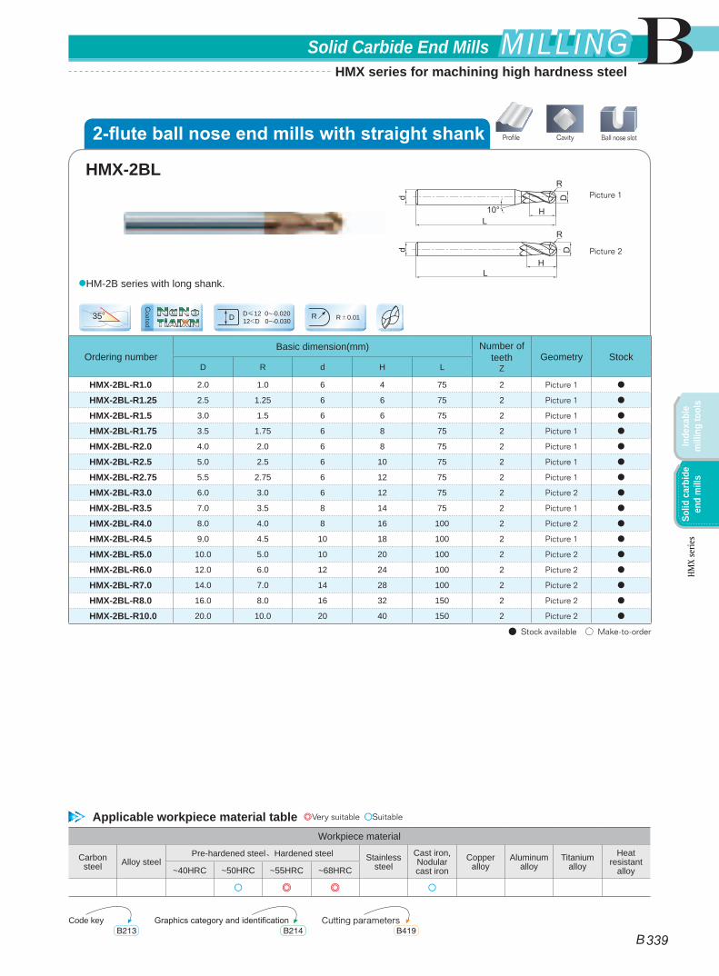
Ordering numberBasic dimension(mm) Number of
teethZ
Geometry StockD R d H L
HMX-2BL-R1.0 2.0 1.0 6 4 75 2 Picture 1 ●
HMX-2BL-R1.25 2.5 1.25 6 6 75 2 Picture 1 ●
HMX-2BL-R1.5 3.0 1.5 6 6 75 2 Picture 1 ●
HMX-2BL-R1.75 3.5 1.75 6 8 75 2 Picture 1 ●
HMX-2BL-R2.0 4.0 2.0 6 8 75 2 Picture 1 ●
HMX-2BL-R2.5 5.0 2.5 6 10 75 2 Picture 1 ●
HMX-2BL-R2.75 5.5 2.75 6 12 75 2 Picture 1 ●
HMX-2BL-R3.0 6.0 3.0 6 12 75 2 Picture 2 ●
HMX-2BL-R3.5 7.0 3.5 8 14 75 2 Picture 1 ●
HMX-2BL-R4.0 8.0 4.0 8 16 100 2 Picture 2 ●
HMX-2BL-R4.5 9.0 4.5 10 18 100 2 Picture 1 ●
HMX-2BL-R5.0 10.0 5.0 10 20 100 2 Picture 2 ●
HMX-2BL-R6.0 12.0 6.0 12 24 100 2 Picture 2 ●
HMX-2BL-R7.0 14.0 7.0 14 28 100 2 Picture 2 ●
HMX-2BL-R8.0 16.0 8.0 16 32 150 2 Picture 2 ●
HMX-2BL-R10.0 20.0 10.0 20 40 150 2 Picture 2 ●
● Stock available ○ Make-to-order
35o D≤12 0~-0.02012<D 0~-0.030D R±0.01R
Picture 1
Picture 2
●HM-2B series with long shank.
Workpiece material
Carbon steel Alloy steel
Pre-hardened steel、Hardened steel Stainless steel
Cast iron, Nodular cast iron
Copper alloy
Aluminum alloy
Titanium alloy
Heat resistant
alloy~40HRC ~50HRC ~55HRC ~68HRC
○ ◎ ◎ ○
HMX-2BL
CavityProfile Ball nose slot
Applicable workpiece material table ◎Very suitable ○Suitable
Code key Cutting parametersGraphics category and identificationB213 B419B214
2-flute ball nose end mills with straight shank
TiAIXNNaNo
Coated
B
B 339
Solid Carbide End Mills MILLINGMILLING
Inde
xabl
e m
illin
g to
ols
Solid
car
bide
en
d m
ills
HMX
serie
s
HMX series for machining high hardness steel
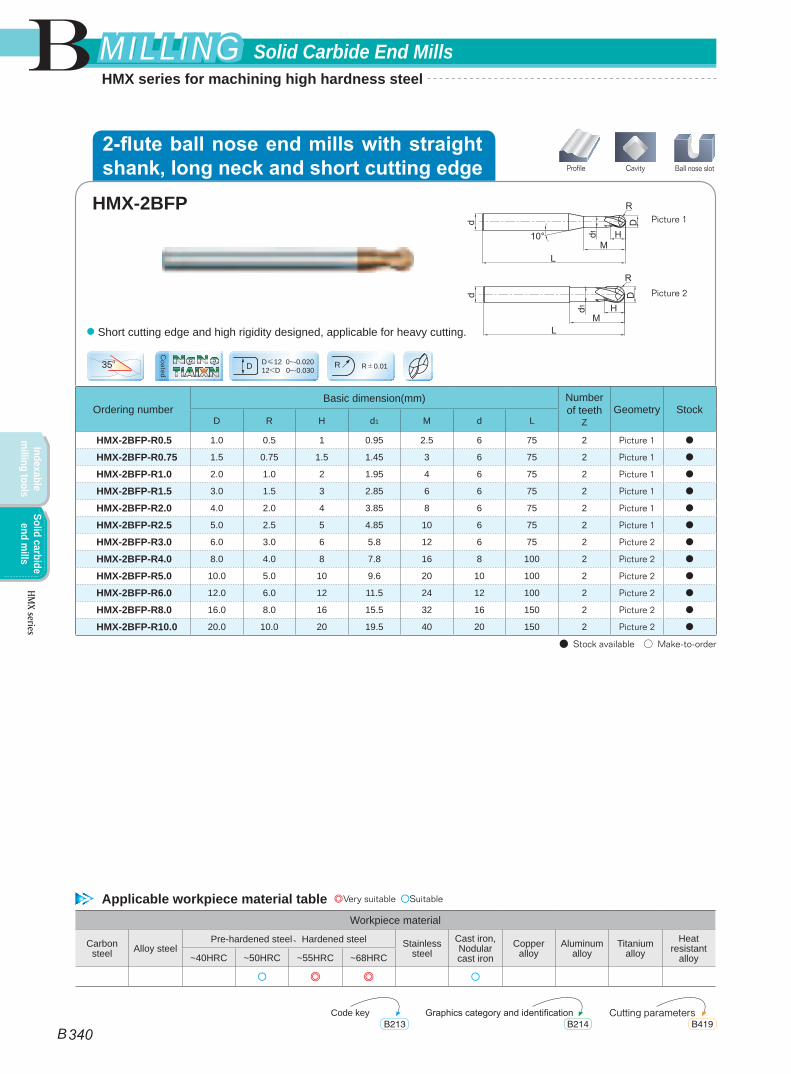
Ordering numberBasic dimension(mm) Number
of teethZ
Geometry StockD R H d1 M d L
HMX-2BFP-R0.5 1.0 0.5 1 0.95 2.5 6 75 2 Picture 1 ●
HMX-2BFP-R0.75 1.5 0.75 1.5 1.45 3 6 75 2 Picture 1 ●
HMX-2BFP-R1.0 2.0 1.0 2 1.95 4 6 75 2 Picture 1 ●
HMX-2BFP-R1.5 3.0 1.5 3 2.85 6 6 75 2 Picture 1 ●
HMX-2BFP-R2.0 4.0 2.0 4 3.85 8 6 75 2 Picture 1 ●
HMX-2BFP-R2.5 5.0 2.5 5 4.85 10 6 75 2 Picture 1 ●
HMX-2BFP-R3.0 6.0 3.0 6 5.8 12 6 75 2 Picture 2 ●
HMX-2BFP-R4.0 8.0 4.0 8 7.8 16 8 100 2 Picture 2 ●
HMX-2BFP-R5.0 10.0 5.0 10 9.6 20 10 100 2 Picture 2 ●
HMX-2BFP-R6.0 12.0 6.0 12 11.5 24 12 100 2 Picture 2 ●
HMX-2BFP-R8.0 16.0 8.0 16 15.5 32 16 150 2 Picture 2 ●
HMX-2BFP-R10.0 20.0 10.0 20 19.5 40 20 150 2 Picture 2 ●
● Stock available ○ Make-to-order
35o D≤12 0~-0.02012<D 0~-0.030D R±0.01R
Picture 1
Picture 2
● Short cutting edge and high rigidity designed, applicable for heavy cutting.
Workpiece material
Carbon steel Alloy steel
Pre-hardened steel、Hardened steel Stainless steel
Cast iron, Nodular cast iron
Copper alloy
Aluminum alloy
Titanium alloy
Heat resistant
alloy~40HRC ~50HRC ~55HRC ~68HRC
○ ◎ ◎ ○
HMX-2BFP
CavityProfile Ball nose slot
Applicable workpiece material table ◎Very suitable ○Suitable
Code key Cutting parametersGraphics category and identificationB213 B419B214
2-flute ball nose end mills with straight shank, long neck and short cutting edge
TiAIXNNaNo
Coated
B
B 340
Solid Carbide End MillsMILLINGMILLING
Indexable m
illing toolsSolid carbide
end mills
HMX series
HMX series for machining high hardness steel
Ordering numberBasic dimension(mm) Number of
teethZ
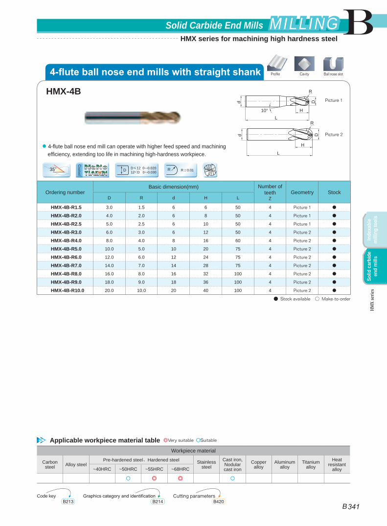
Geometry StockD R d H L
HMX-4B-R1.5 3.0 1.5 6 6 50 4 Picture 1 ●
HMX-4B-R2.0 4.0 2.0 6 8 50 4 Picture 1 ●
HMX-4B-R2.5 5.0 2.5 6 10 50 4 Picture 1 ●
HMX-4B-R3.0 6.0 3.0 6 12 50 4 Picture 2 ●
HMX-4B-R4.0 8.0 4.0 8 16 60 4 Picture 2 ●
HMX-4B-R5.0 10.0 5.0 10 20 75 4 Picture 2 ●
HMX-4B-R6.0 12.0 6.0 12 24 75 4 Picture 2 ●
HMX-4B-R7.0 14.0 7.0 14 28 75 4 Picture 2 ●
HMX-4B-R8.0 16.0 8.0 16 32 100 4 Picture 2 ●
HMX-4B-R9.0 18.0 9.0 18 36 100 4 Picture 2 ●
HMX-4B-R10.0 20.0 10.0 20 40 100 4 Picture 2 ●
● Stock available ○ Make-to-order
35o D≤12 0~-0.02012<D 0~-0.030D R±0.01R
dd
L
L
H
H
DD
10°
R
R
Picture 1
Picture 2
● 4-flute ball nose end mill can operate with higher feed speed and machining efficiency, extending too life in machining high-hardness workpiece.
Workpiece material
Carbon steel Alloy steel
Pre-hardened steel、Hardened steel Stainless steel
Cast iron, Nodular cast iron
Copper alloy
Aluminum alloy
Titanium alloy
Heat resistant
alloy~40HRC ~50HRC ~55HRC ~68HRC
○ ◎ ◎ ○
HMX-4B
CavityProfile Ball nose slot
Applicable workpiece material table ◎Very suitable ○Suitable
Code key Cutting parametersGraphics category and identificationB213 B420B214
4-flute ball nose end mills with straight shank
TiAIXNNaNo
Coated
B
B 341
Solid Carbide End Mills MILLINGMILLING
Inde
xabl
e m
illin
g to
ols
Solid
car
bide
en
d m
ills
HMX
serie
s
HMX series for machining high hardness steel
Ordering numberBasic dimension(mm) Number of
teethZ
Geometry StockD R d H L
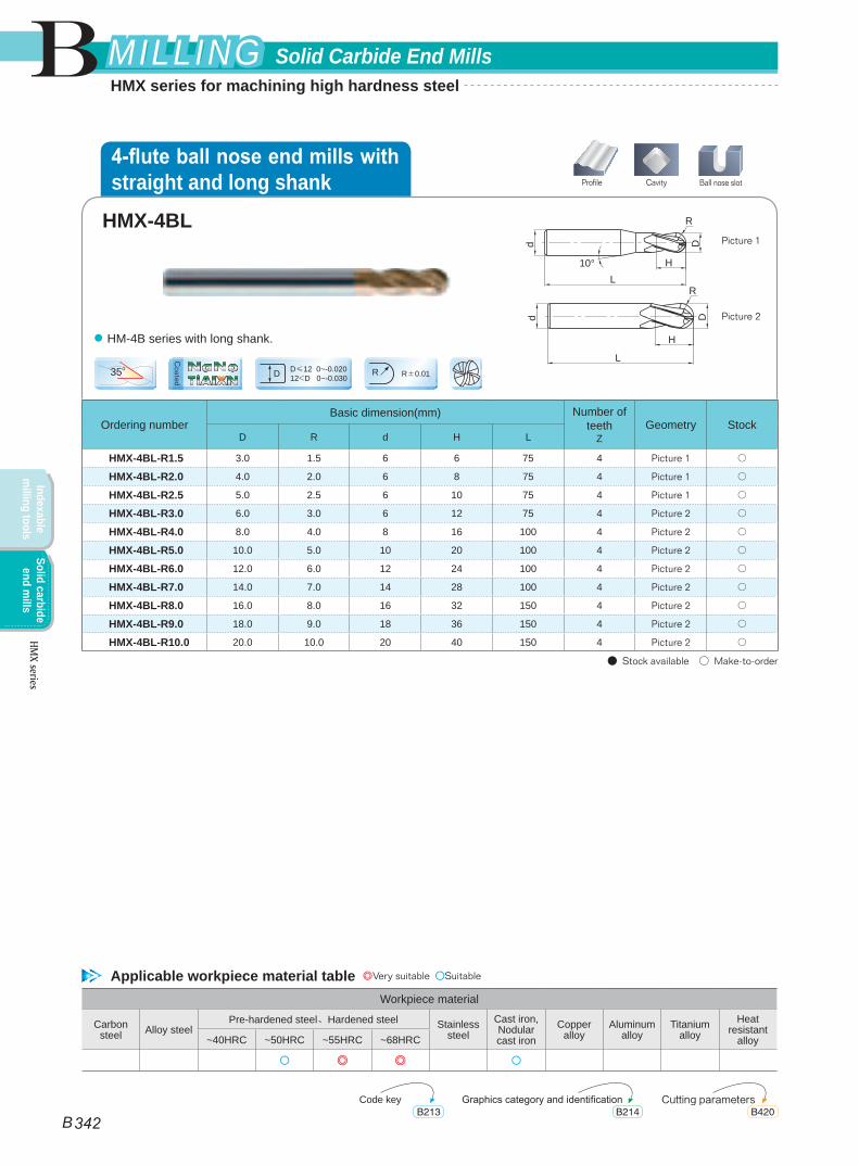
HMX-4BL-R1.5 3.0 1.5 6 6 75 4 Picture 1 ○
HMX-4BL-R2.0 4.0 2.0 6 8 75 4 Picture 1 ○
HMX-4BL-R2.5 5.0 2.5 6 10 75 4 Picture 1 ○
HMX-4BL-R3.0 6.0 3.0 6 12 75 4 Picture 2 ○
HMX-4BL-R4.0 8.0 4.0 8 16 100 4 Picture 2 ○
HMX-4BL-R5.0 10.0 5.0 10 20 100 4 Picture 2 ○
HMX-4BL-R6.0 12.0 6.0 12 24 100 4 Picture 2 ○
HMX-4BL-R7.0 14.0 7.0 14 28 100 4 Picture 2 ○
HMX-4BL-R8.0 16.0 8.0 16 32 150 4 Picture 2 ○
HMX-4BL-R9.0 18.0 9.0 18 36 150 4 Picture 2 ○
HMX-4BL-R10.0 20.0 10.0 20 40 150 4 Picture 2 ○
● Stock available ○ Make-to-order
35o D≤12 0~-0.02012<D 0~-0.030D R±0.01R
dd
L
L
H
H
DD
10°
R
R
Picture 1
Picture 2
● HM-4B series with long shank.
Workpiece material
Carbon steel Alloy steel
Pre-hardened steel、Hardened steel Stainless steel
Cast iron, Nodular cast iron
Copper alloy
Aluminum alloy
Titanium alloy
Heat resistant
alloy~40HRC ~50HRC ~55HRC ~68HRC
○ ◎ ◎ ○
HMX-4BL
CavityProfile Ball nose slot
Applicable workpiece material table ◎Very suitable ○Suitable
Code key Cutting parametersGraphics category and identificationB213 B420B214
4-flute ball nose end mills with straight and long shank
TiAIXNNaNo
Coated
B
B 342
Solid Carbide End MillsMILLINGMILLING
Indexable m
illing toolsSolid carbide
end mills
HMX series
HMX series for machining high hardness steel
Ordering numberBasic dimension(mm) Number of
teethZ
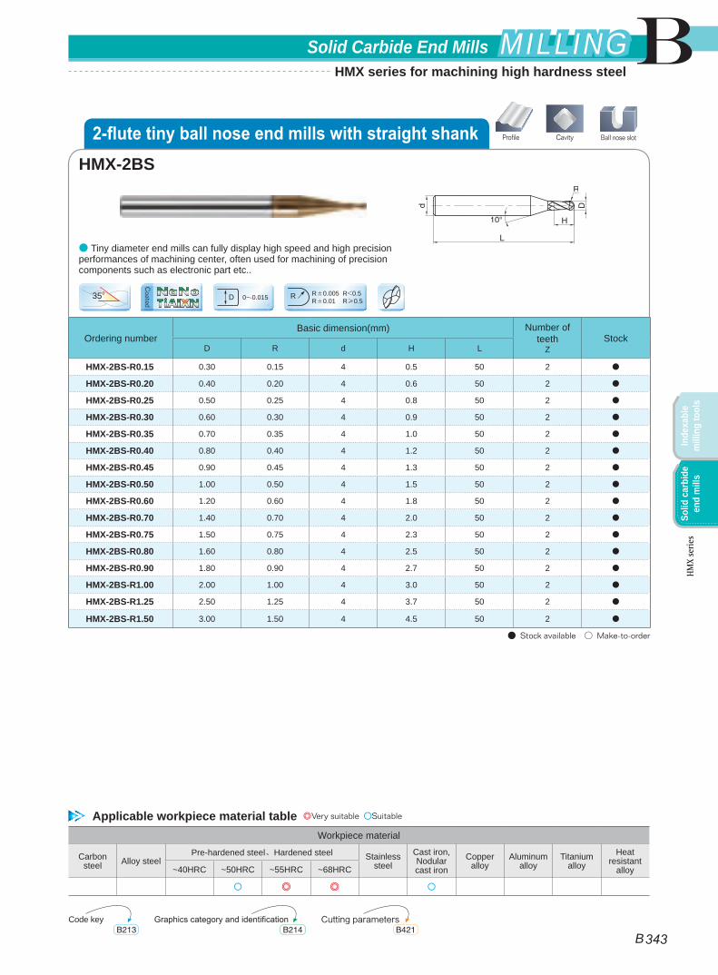
StockD R d H L
HMX-2BS-R0.15 0.30 0.15 4 0.5 50 2 ●
HMX-2BS-R0.20 0.40 0.20 4 0.6 50 2 ●
HMX-2BS-R0.25 0.50 0.25 4 0.8 50 2 ●
HMX-2BS-R0.30 0.60 0.30 4 0.9 50 2 ●
HMX-2BS-R0.35 0.70 0.35 4 1.0 50 2 ●
HMX-2BS-R0.40 0.80 0.40 4 1.2 50 2 ●
HMX-2BS-R0.45 0.90 0.45 4 1.3 50 2 ●
HMX-2BS-R0.50 1.00 0.50 4 1.5 50 2 ●
HMX-2BS-R0.60 1.20 0.60 4 1.8 50 2 ●
HMX-2BS-R0.70 1.40 0.70 4 2.0 50 2 ●
HMX-2BS-R0.75 1.50 0.75 4 2.3 50 2 ●
HMX-2BS-R0.80 1.60 0.80 4 2.5 50 2 ●
HMX-2BS-R0.90 1.80 0.90 4 2.7 50 2 ●
HMX-2BS-R1.00 2.00 1.00 4 3.0 50 2 ●
HMX-2BS-R1.25 2.50 1.25 4 3.7 50 2 ●
HMX-2BS-R1.50 3.00 1.50 4 4.5 50 2 ●
● Stock available ○ Make-to-order
35o0~-0.015D R±0.005 R<0.5
R±0.01 R≥0.5R
● Tiny diameter end mills can fully display high speed and high precision performances of machining center, often used for machining of precision components such as electronic part etc..
Workpiece material
Carbon steel Alloy steel
Pre-hardened steel、Hardened steel Stainless steel
Cast iron, Nodular cast iron
Copper alloy
Aluminum alloy
Titanium alloy
Heat resistant
alloy~40HRC ~50HRC ~55HRC ~68HRC
○ ◎ ◎ ○
HMX-2BS
CavityProfile Ball nose slot
Applicable workpiece material table ◎Very suitable ○Suitable
Code key Cutting parametersGraphics category and identificationB213 B421B214
2-flute tiny ball nose end mills with straight shank
TiAIXNNaNo
Coated
B
B 343
Solid Carbide End Mills MILLINGMILLING
Inde
xabl
e m
illin
g to
ols
Solid
car
bide
en
d m
ills
HMX
serie
s
HMX series for machining high hardness steel
Ordering numberBasic dimension(mm) Number of
teethZ
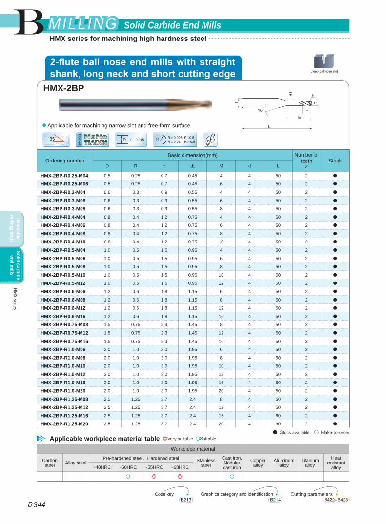
StockD R H d1 M d L
HMX-2BP-R0.25-M04 0.5 0.25 0.7 0.45 4 4 50 2 ●
HMX-2BP-R0.25-M06 0.5 0.25 0.7 0.45 6 4 50 2 ●
HMX-2BP-R0.3-M04 0.6 0.3 0.9 0.55 4 4 50 2 ●
HMX-2BP-R0.3-M06 0.6 0.3 0.9 0.55 6 4 50 2 ●
HMX-2BP-R0.3-M08 0.6 0.3 0.9 0.55 8 4 50 2 ●
HMX-2BP-R0.4-M04 0.8 0.4 1.2 0.75 4 4 50 2 ●
HMX-2BP-R0.4-M06 0.8 0.4 1.2 0.75 6 4 50 2 ●
HMX-2BP-R0.4-M08 0.8 0.4 1.2 0.75 8 4 50 2 ●
HMX-2BP-R0.4-M10 0.8 0.4 1.2 0.75 10 4 50 2 ●
HMX-2BP-R0.5-M04 1.0 0.5 1.5 0.95 4 4 50 2 ●
HMX-2BP-R0.5-M06 1.0 0.5 1.5 0.95 6 4 50 2 ●
HMX-2BP-R0.5-M08 1.0 0.5 1.5 0.95 8 4 50 2 ●
HMX-2BP-R0.5-M10 1.0 0.5 1.5 0.95 10 4 50 2 ●
HMX-2BP-R0.5-M12 1.0 0.5 1.5 0.95 12 4 50 2 ●
HMX-2BP-R0.6-M06 1.2 0.6 1.8 1.15 6 4 50 2 ●
HMX-2BP-R0.6-M08 1.2 0.6 1.8 1.15 8 4 50 2 ●
HMX-2BP-R0.6-M12 1.2 0.6 1.8 1.15 12 4 50 2 ●
HMX-2BP-R0.6-M16 1.2 0.6 1.8 1.15 16 4 50 2 ●
HMX-2BP-R0.75-M08 1.5 0.75 2.3 1.45 8 4 50 2 ●
HMX-2BP-R0.75-M12 1.5 0.75 2.3 1.45 12 4 50 2 ●
HMX-2BP-R0.75-M16 1.5 0.75 2.3 1.45 16 4 50 2 ●
HMX-2BP-R1.0-M06 2.0 1.0 3.0 1.95 6 4 50 2 ●
HMX-2BP-R1.0-M08 2.0 1.0 3.0 1.95 8 4 50 2 ●
HMX-2BP-R1.0-M10 2.0 1.0 3.0 1.95 10 4 50 2 ●
HMX-2BP-R1.0-M12 2.0 1.0 3.0 1.95 12 4 50 2 ●
HMX-2BP-R1.0-M16 2.0 1.0 3.0 1.95 16 4 50 2 ●
HMX-2BP-R1.0-M20 2.0 1.0 3.0 1.95 20 4 50 2 ●
HMX-2BP-R1.25-M08 2.5 1.25 3.7 2.4 8 4 50 2 ●
HMX-2BP-R1.25-M12 2.5 1.25 3.7 2.4 12 4 50 2 ●
HMX-2BP-R1.25-M16 2.5 1.25 3.7 2.4 16 4 60 2 ●
HMX-2BP-R1.25-M20 2.5 1.25 3.7 2.4 20 4 60 2 ●
● Stock available ○ Make-to-order
35o0~-0.015D R±0.005 R<0.5
R±0.01 R≥0.5R
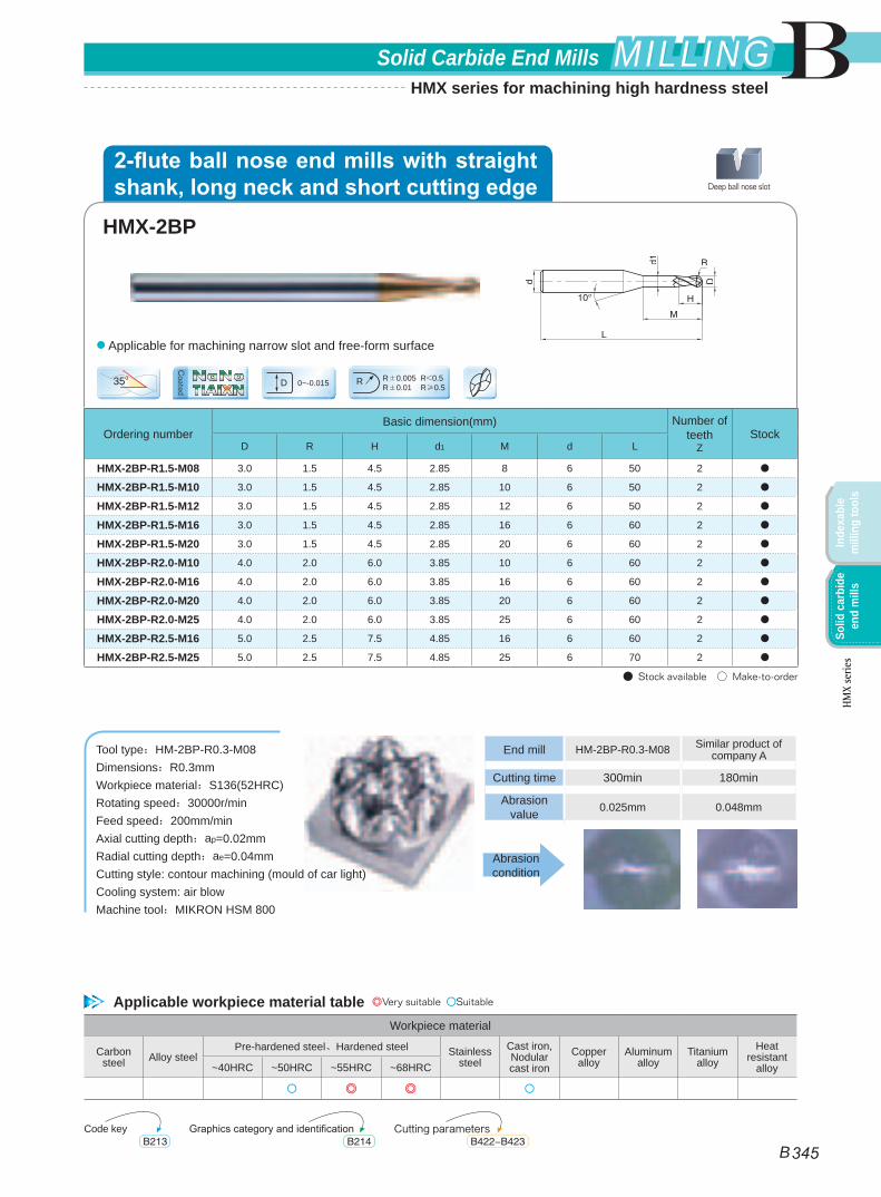
● Applicable for machining narrow slot and free-form surface.
Workpiece material
Carbon steel Alloy steel
Pre-hardened steel、Hardened steel Stainless steel
Cast iron, Nodular cast iron
Copper alloy
Aluminum alloy
Titanium alloy
Heat resistant
alloy~40HRC ~50HRC ~55HRC ~68HRC
○ ◎ ◎ ○
HMX-2BP
Deep ball nose slot
Applicable workpiece material table ◎Very suitable ○Suitable
Code key Cutting parametersGraphics category and identificationB213 B422-B423B214
2-flute ball nose end mills with straight shank, long neck and short cutting edge
TiAIXNNaNo
Coated
B
B 344
Solid Carbide End MillsMILLINGMILLING
Indexable m
illing toolsSolid carbide
end mills
HMX series
HMX series for machining high hardness steel
Ordering numberBasic dimension(mm) Number of
teethZ
StockD R H d1 M d L
HMX-2BP-R1.5-M08 3.0 1.5 4.5 2.85 8 6 50 2 ●
HMX-2BP-R1.5-M10 3.0 1.5 4.5 2.85 10 6 50 2 ●
HMX-2BP-R1.5-M12 3.0 1.5 4.5 2.85 12 6 50 2 ●
HMX-2BP-R1.5-M16 3.0 1.5 4.5 2.85 16 6 60 2 ●
HMX-2BP-R1.5-M20 3.0 1.5 4.5 2.85 20 6 60 2 ●
HMX-2BP-R2.0-M10 4.0 2.0 6.0 3.85 10 6 60 2 ●
HMX-2BP-R2.0-M16 4.0 2.0 6.0 3.85 16 6 60 2 ●
HMX-2BP-R2.0-M20 4.0 2.0 6.0 3.85 20 6 60 2 ●
HMX-2BP-R2.0-M25 4.0 2.0 6.0 3.85 25 6 60 2 ●
HMX-2BP-R2.5-M16 5.0 2.5 7.5 4.85 16 6 60 2 ●
HMX-2BP-R2.5-M25 5.0 2.5 7.5 4.85 25 6 70 2 ●
● Stock available ○ Make-to-order
35o0~-0.015D R±0.005 R<0.5
R±0.01 R≥0.5R
● Applicable for machining narrow slot and free-form surface
Tool type:HM-2BP-R0.3-M08Dimensions:R0.3mmWorkpiece material:S136(52HRC)Rotating speed:30000r/min Feed speed:200mm/minAxial cutting depth:ap=0.02mmRadial cutting depth:ae=0.04mmCutting style: contour machining (mould of car light)Cooling system: air blowMachine tool:MIKRON HSM 800
Workpiece material
Carbon steel Alloy steel
Pre-hardened steel、Hardened steel Stainless steel
Cast iron, Nodular cast iron
Copper alloy
Aluminum alloy
Titanium alloy
Heat resistant
alloy~40HRC ~50HRC ~55HRC ~68HRC
○ ◎ ◎ ○
HMX-2BP
Deep ball nose slot
End mill HM-2BP-R0.3-M08 Similar product of company A
Cutting time 300min 180min
Abrasion value 0.025mm 0.048mm
Abrasion condition
Applicable workpiece material table ◎Very suitable ○Suitable
Code key Cutting parametersGraphics category and identificationB213 B422-B423B214
2-flute ball nose end mills with straight shank, long neck and short cutting edge
TiAIXNNaNo
Coated
B
B 345
Solid Carbide End Mills MILLINGMILLING
Inde
xabl
e m
illin
g to
ols
Solid
car
bide
en
d m
ills
HMX
serie
s
HMX series for machining high hardness steel
Ordering numberBasic dimension(mm) Number of
teethZ
Geometry StockD R d H L
HMX-4R-D3.0R0.2 3.0 0.2 4 8 50 4 Picture 1 ●
HMX-4R-D4.0R0.3 4.0 0.3 4 10 50 4 Picture 2 ●
HMX-4R-D4.0R0.5 4.0 0.5 4 10 50 4 Picture 2 ●
HMX-4R-D5.0R0.5 5.0 0.5 6 13 50 4 Picture 1 ●
HMX-4R-D5.0R1.0 5.0 1.0 6 13 50 4 Picture 1 ●
HMX-4R-D6.0R0.5 6.0 0.5 6 16 50 4 Picture 2 ●
HMX-4R-D6.0R1.0 6.0 1.0 6 16 50 4 Picture 2 ●
HMX-4R-D8.0R0.5 8.0 0.5 8 20 60 4 Picture 2 ●
HMX-4R-D8.0R1.0 8.0 1.0 8 20 60 4 Picture 2 ●
HMX-4R-D10.0R0.5 10.0 0.5 10 25 75 4 Picture 2 ●
HMX-4R-D10.0R1.0 10.0 1.0 10 25 75 4 Picture 2 ●
HMX-4R-D10.0R2.0 10.0 2.0 10 25 75 4 Picture 2 ●
HMX-4R-D10.0R3.0 10.0 3.0 10 25 75 4 Picture 2 ●
HMX-4R-D12.0R0.5 12.0 0.5 12 30 75 4 Picture 2 ●
HMX-4R-D12.0R1.0 12.0 1.0 12 30 75 4 Picture 2 ●
HMX-4R-D12.0R2.0 12.0 2.0 12 30 75 4 Picture 2 ●
HMX-4R-D12.0R3.0 12.0 3.0 12 30 75 4 Picture 2 ●
● Stock available ○ Make-to-order
35o0~-0.020D
Picture 1
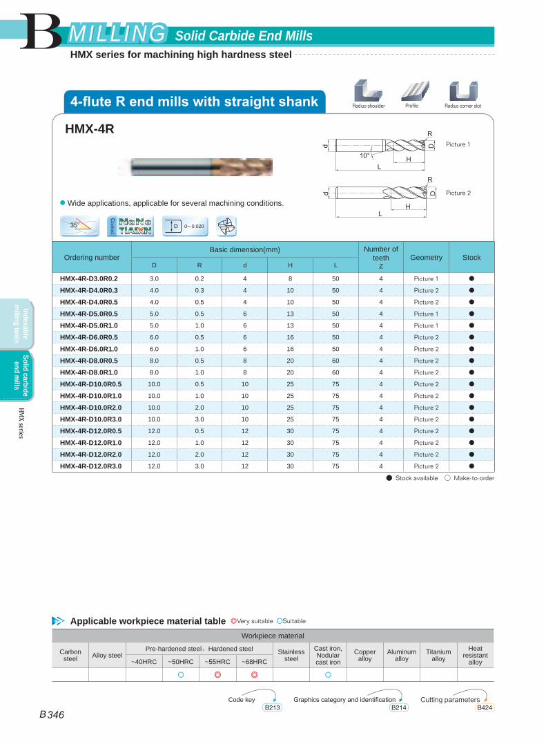
Picture 2● Wide applications, applicable for several machining conditions.
Workpiece material
Carbon steel Alloy steel
Pre-hardened steel、Hardened steel Stainless steel
Cast iron, Nodular cast iron
Copper alloy
Aluminum alloy
Titanium alloy
Heat resistant
alloy~40HRC ~50HRC ~55HRC ~68HRC
○ ◎ ◎ ○
HMX-4R
ProfileRadius shoulder Radius corner slot
Applicable workpiece material table ◎Very suitable ○Suitable
Code key Cutting parametersGraphics category and identificationB213 B424B214
4-flute R end mills with straight shank
TiAIXNNaNo
Coated
B
B 346
Solid Carbide End MillsMILLINGMILLING
Indexable m
illing toolsSolid carbide
end mills
HMX series
HMX series for machining high hardness steel
Ordering numberBasic dimension(mm) Number of
teethZ
StockD R d H L
HMX-4RF-D6.0R0.5 6.0 0.5 6 6 50 4 ●
HMX-4RF-D6.0R1.0 6.0 1.0 6 6 50 4 ●
HMX-4RF-D8.0R0.5 8.0 0.5 8 8 60 4 ●
HMX-4RF-D8.0R1.0 8.0 1.0 8 8 60 4 ●
HMX-4RF-10.0R0.5 10.0 0.5 10 10 75 4 ●
HMX-4RF-D10.0R1.0 10.0 1.0 10 10 75 4 ●
HMX-4RF-D10.0R2.0 10.0 2.0 10 10 75 4 ●
HMX-4RF-D12.0R0.5 12.0 0.5 12 12 75 4 ●
HMX-4RF-D12.0R1.0 12.0 1.0 12 12 75 4 ●
HMX-4RF-D12.0R2.0 12.0 2.0 12 12 75 4 ●
● Stock available ○ Make-to-order
35o0~-0.020D
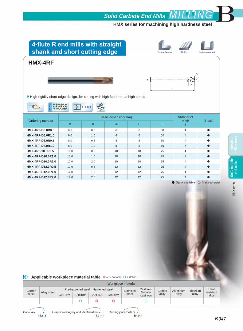
● High-rigidity short edge design, for cutting with high feed rate at high speed.
Workpiece material
Carbon steel Alloy steel
Pre-hardened steel、Hardened steel Stainless steel
Cast iron, Nodular cast iron
Copper alloy
Aluminum alloy
Titanium alloy
Heat resistant
alloy~40HRC ~50HRC ~55HRC ~68HRC
○ ◎ ◎ ○
HMX-4RF
ProfileRadius shoulder Radius corner slot
Applicable workpiece material table ◎Very suitable ○Suitable
Code key Cutting parametersGraphics category and identificationB213 B424B214
4-flute R end mills with straight shank and short cutting edge
TiAIXNNaNo
Coated
B
B 347
Solid Carbide End Mills MILLINGMILLING
Inde
xabl
e m
illin
g to
ols
Solid
car
bide
en
d m
ills
HMX
serie
s
HMX series for machining high hardness steel
Ordering numberBasic dimension(mm) Number of
teethZ
StockD R d d1 H M L
HMX-4RP-D6.0R0.5 6.0 0.5 6 5.8 6 18 75 4 ●
HMX-4RP-D6.0R1.0 6.0 1.0 6 5.8 6 18 75 4 ●
HMX-4RP-D8.0R0.5 8.0 0.5 8 7.8 8 24 100 4 ●
HMX-4RP-D8.0R1.0 8.0 1.0 8 7.8 8 24 100 4 ●
HMX-4RP-10.0R0.5 10.0 0.5 10 9.6 10 30 100 4 ●
HMX-4RP-10.0R1.0 10.0 1.0 10 9.6 10 30 100 4 ●
HMX-4RP-10.0R2.0 10.0 2.0 10 9.6 10 30 100 4 ●
HMX-4RP-12.0R0.5 12.0 0.5 12 11.5 12 36 100 4 ●
HMX-4RP-12.0R1.0 12.0 1.0 12 11.5 12 36 100 4 ●
HMX-4RP-12.0R2.0 12.0 2.0 12 11.5 12 36 100 4 ●
HMX-4RP-D16.0R1.0 16.0 1.0 16 15.5 16 40 150 4 ●
HMX-4RP-D16.0R2.0 16.0 2.0 16 15.5 16 40 150 4 ●
● Stock available ○ Make-to-order
35o
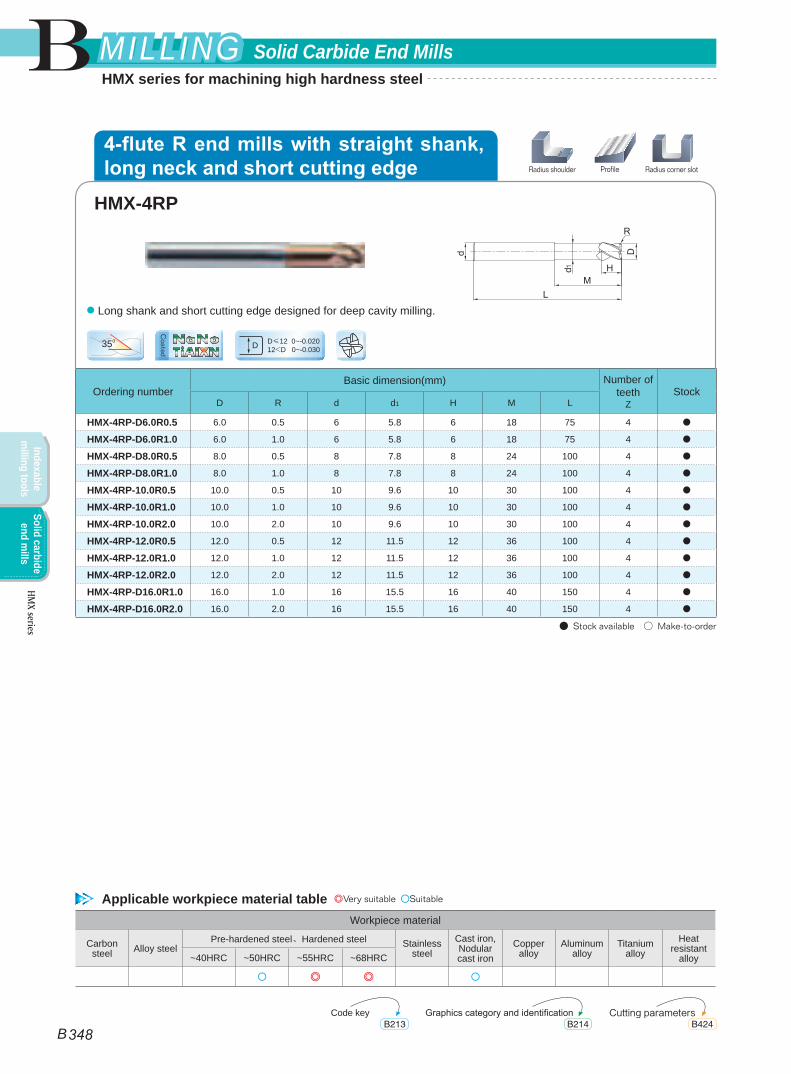
● Long shank and short cutting edge designed for deep cavity milling.
D≤12 0~-0.02012<D 0~-0.030D
Workpiece material
Carbon steel Alloy steel
Pre-hardened steel、Hardened steel Stainless steel
Cast iron, Nodular cast iron
Copper alloy
Aluminum alloy
Titanium alloy
Heat resistant
alloy~40HRC ~50HRC ~55HRC ~68HRC
○ ◎ ◎ ○
HMX-4RP
ProfileRadius shoulder Radius corner slot
Applicable workpiece material table ◎Very suitable ○Suitable
Code key Cutting parametersGraphics category and identificationB213 B424B214
4-flute R end mills with straight shank, long neck and short cutting edge
TiAIXNNaNo
Coated
B
B 348
Solid Carbide End MillsMILLINGMILLING
Indexable m
illing toolsSolid carbide
end mills
HMX series
HMX series for machining high hardness steel
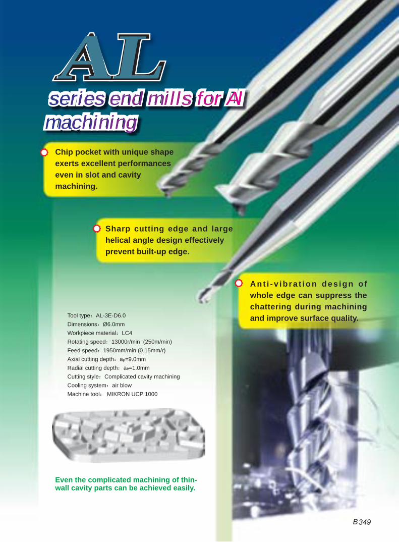
Chip pocket with unique shape exerts excellent performances even in slot and cavity machining.
Sharp cutting edge and large helical angle design effectively prevent built-up edge.
Ant i -v ib ra t ion des ign o f whole edge can suppress the chattering during machining and improve surface quality.
ALAL
Even the complicated machining of thin-wall cavity parts can be achieved easily.
Tool type:AL-3E-D6.0Dimensions:Ø6.0mmWorkpiece material:LC4Rotating speed:13000r/min (250m/min)Feed speed:1950mm/min (0.15mm/r)Axial cutting depth:ap=9.0mmRadial cutting depth:ae=1.0mmCutting style:Complicated cavity machiningCooling system:air blowMachine tool: MIKRON UCP 1000
series end mills for Al machining
B 349
15mm
2.5mm
AL-3W-D10.0
General end mills
Comparison of AL-3W end mills with general end mills
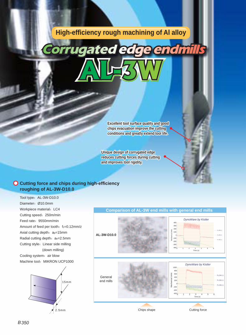
Excellent tool surface quality and good chips evacuation improve the cutting conditions and greatly extend tool life.
Unique design of corrugated edge reduces cutting forces during cutting and improves tool rigidity.
Tool type:AL-3W-D10.0Diameter:Ø10.0mmWorkpiece material:LC4Cutting speed:250m/minFeed rate:9550mm/minAmount of feed per tooth:fz=0.12mm/zAxial cutting depth:ap=15mmRadial cutting depth:ae=2.5mmCutting style:Linear side milling (down milling)Cooling system:air blowMachine tool:MIKRON UCP1000
Corrugated edge end mills
Cutting force and chips during high-efficiency roughing of AL-3W-D10.0
Chips shape Cutting force
0 1 2 3 4 5 6-400
-300
-200
-100
0
100
200
300
400
Fy (M.U.)
Fx (M.U.)
Fz (M.U.)
Time (s)
Mec
hani
cal U
nits
DynoWare by Kistler
0 1 2 3 4 5 6-600
-400
-200
0
200
400
600
800
1000
Fy (M.U.)
Fx (M.U.)
Fz (M.U.)
Time (s)
Mec
hani
cal U
nits
DynoWare by Kistler
AL-3WAL-3W
High-efficiency rough machining of Al alloy
B 350

Ordering numberBasic dimension(mm) Number of
teethZ
Geometry StockD d H L
AL-2E-D1.0 1.0 4 3 50 2 Picture 1 ●
AL-2E-D1.5 1.5 4 4 50 2 Picture 1 ●
AL-2E-D2.0 2.0 4 6 50 2 Picture 1 ●
AL-2E-D2.5 2.5 4 7 50 2 Picture 1 ●
AL-2E-D3.0 3.0 6 9 50 2 Picture 1 ●
AL-2E-D4.0 4.0 6 12 50 2 Picture 1 ●
AL-2E-D5.0 5.0 6 15 50 2 Picture 1 ●
AL-2E-D6.0 6.0 6 18 60 2 Picture 2 ●
AL-2E-D8.0 8.0 8 20 60 2 Picture 2 ●
AL-2E-D10.0 10.0 10 30 75 2 Picture 2 ●
AL-2E-D12.0 12.0 12 32 75 2 Picture 2 ●
AL-2E-D16.0 16.0 16 45 100 2 Picture 2 ●
AL-2E-D20.0 20.0 20 45 100 2 Picture 2 ●
● Stock available ○ Make-to-order
Workpiece material
Carbon steel Alloy steel
Pre-hardened steel、Hardened steel Stainless steel
Cast iron, Nodular cast iron
Copper alloy
Aluminum alloy
Titanium alloy
Heat resistant
alloy~40HRC ~50HRC ~55HRC ~68HRC
◎
55o D≤12 0~-0.02012<D 0~-0.030D
Picture 1
Picture 2● Good chip removal performance, high machining efficiency.
AL-2E
Side face Step shoulder Straight slot
Applicable workpiece material table ◎Very suitable ○Suitable
Code key Cutting parametersGraphics category and identificationB213 B425B214
2-flute flattened end mills with straight shank
B
B 351
Solid Carbide End Mills MILLINGMILLING
Inde
xabl
e m
illin
g to
ols
Solid
car
bide
en
d m
ills
AL series for machining aluminum
AL se
ries
Workpiece material
Carbon steel Alloy steel
Pre-hardened steel、Hardened steel Stainless steel
Cast iron, Nodular cast iron
Copper alloy
Aluminum alloy
Titanium alloy
Heat resistant
alloy~40HRC ~50HRC ~55HRC ~68HRC
◎
Ordering numberBasic dimension(mm) Number of
teethZ
Geometry StockD d H L
AL-2EL-D3.0 3.0 6 12 60 2 Picture 1 ●
AL-2EL-D4.0 4.0 6 16 60 2 Picture 1 ●
AL-2EL-D5.0 5.0 6 20 60 2 Picture 1 ●
AL-2EL-D6.0 6.0 6 25 75 2 Picture 2 ●
AL-2EL-D8.0 8.0 8 32 75 2 Picture 2 ●
AL-2EL-D10.0 10.0 10 45 100 2 Picture 2 ●
AL-2EL-D12.0 12.0 12 45 100 2 Picture 2 ●
AL-2EL-D16.0 16.0 16 65 150 2 Picture 2 ●
AL-2EL-D20.0 20.0 20 75 150 2 Picture 2 ●
● Stock available ○ Make-to-order
55o D≤12 0~-0.02012<D 0~-0.030D
Picture 1
Picture 2● AL-2E series with long cutting edge.
AL-2EL
Side face Step shoulder Straight slot
Applicable workpiece material table ◎Very suitable ○Suitable
Code key Cutting parametersGraphics category and identificationB213 B425B214
2-flute flattened end mills with straight shank and long cutting edge
B
B 352
Solid Carbide End MillsMILLINGMILLING
Indexable m
illing toolsSolid carbide
end mills
AL series for machining aluminum
AL series
Ordering numberBasic dimension(mm) Number of
teethZ
Geometry StockD d H L
AL-3E-D1.0 1.0 4 3 50 3 Picture 1 ●
AL-3E-D1.5 1.5 4 4 50 3 Picture 1 ●
AL-3E-D2.0 2.0 4 6 50 3 Picture 1 ●
AL-3E-D2.5 2.5 4 7 50 3 Picture 1 ●
AL-3E-D3.0 3.0 6 9 50 3 Picture 1 ●
AL-3E-D4.0 4.0 6 12 50 3 Picture 1 ●
AL-3E-D5.0 5.0 6 15 50 3 Picture 1 ●
AL-3E-D6.0 6.0 6 18 60 3 Picture 2 ●
AL-3E-D8.0 8.0 8 20 60 3 Picture 2 ●
AL-3E-D10.0 10.0 10 30 75 3 Picture 2 ●
AL-3E-D12.0 12.0 12 32 75 3 Picture 2 ●
AL-3E-D16.0 16.0 16 45 100 3 Picture 2 ●
AL-3E-D20.0 20.0 20 45 100 3 Picture 2 ●
● Stock available ○ Make-to-order
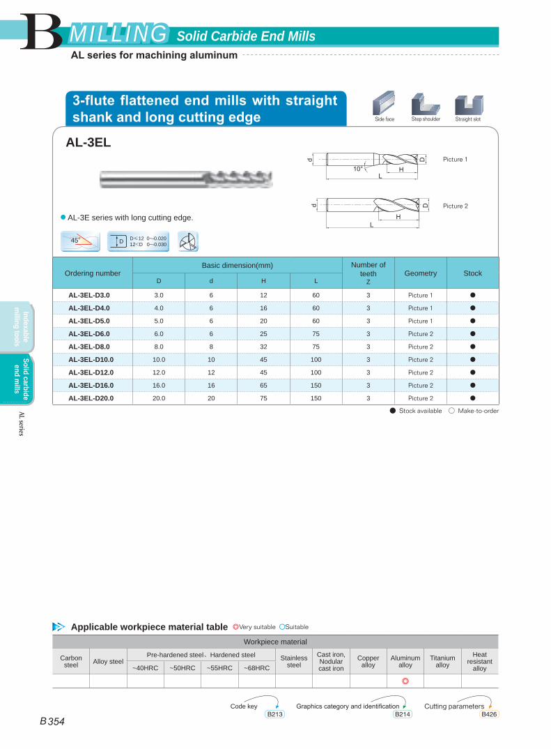
D≤12 0~-0.02012<D 0~-0.030D
Picture 1
Picture 2● Outstanding cutting performance with no chattering, achieving high-precision machining.
45o
Workpiece material
Carbon steel Alloy steel
Pre-hardened steel、Hardened steel Stainless steel
Cast iron, Nodular cast iron
Copper alloy
Aluminum alloy
Titanium alloy
Heat resistant
alloy~40HRC ~50HRC ~55HRC ~68HRC
◎
AL-3E
Side face Step shoulder Straight slot
Applicable workpiece material table ◎Very suitable ○Suitable
Code key Cutting parametersGraphics category and identificationB213 B426B214
3-flute flattened end mills with straight shank
B
B 353
Solid Carbide End Mills MILLINGMILLING
Inde
xabl
e m
illin
g to
ols
Solid
car
bide
en
d m
ills
AL series for machining aluminum
AL se
ries
Ordering numberBasic dimension(mm) Number of
teethZ
Geometry StockD d H L
AL-3EL-D3.0 3.0 6 12 60 3 Picture 1 ●
AL-3EL-D4.0 4.0 6 16 60 3 Picture 1 ●
AL-3EL-D5.0 5.0 6 20 60 3 Picture 1 ●
AL-3EL-D6.0 6.0 6 25 75 3 Picture 2 ●
AL-3EL-D8.0 8.0 8 32 75 3 Picture 2 ●
AL-3EL-D10.0 10.0 10 45 100 3 Picture 2 ●
AL-3EL-D12.0 12.0 12 45 100 3 Picture 2 ●
AL-3EL-D16.0 16.0 16 65 150 3 Picture 2 ●
AL-3EL-D20.0 20.0 20 75 150 3 Picture 2 ●
● Stock available ○ Make-to-order
D≤12 0~-0.02012<D 0~-0.030D
Picture 1
Picture 2
● AL-3E series with long cutting edge.
45o
Workpiece material
Carbon steel Alloy steel
Pre-hardened steel、Hardened steel Stainless steel
Cast iron, Nodular cast iron
Copper alloy
Aluminum alloy
Titanium alloy
Heat resistant
alloy~40HRC ~50HRC ~55HRC ~68HRC
◎
AL-3EL
Side face Step shoulder Straight slot
Applicable workpiece material table ◎Very suitable ○Suitable
Code key Cutting parametersGraphics category and identificationB213 B426B214
3-flute flattened end mills with straight shank and long cutting edge
B
B 354
Solid Carbide End MillsMILLINGMILLING
Indexable m
illing toolsSolid carbide
end mills
AL series for machining aluminum
AL series
Ordering numberBasic dimension(mm) Number of
teethZ
Geometry StockD R d H L
AL-2B-R1.0 2.0 1.0 6 4 60 2 Picture 1 ●
AL-2B-R1.5 3.0 1.5 6 6 60 2 Picture 1 ●
AL-2B-R2.0 4.0 2.0 6 8 60 2 Picture 1 ●
AL-2B-R2.5 5.0 2.5 6 10 60 2 Picture 1 ●
AL-2B-R3.0 6.0 3.0 6 12 60 2 Picture 2 ●
AL-2B-R4.0 8.0 4.0 8 16 75 2 Picture 2 ●
AL-2B-R5.0 10.0 5.0 10 20 75 2 Picture 2 ●
AL-2B-R6.0 12.0 6.0 12 24 75 2 Picture 2 ●
● Stock available ○ Make-to-order
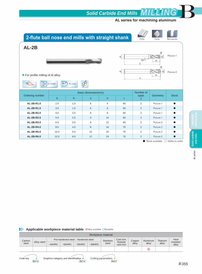
35oR±0.01R
Picture 1
Picture 2● For profile milling of Al alloy.
0~-0.020D
Workpiece material
Carbon steel Alloy steel
Pre-hardened steel、Hardened steel Stainless steel
Cast iron, Nodular cast iron
Copper alloy
Aluminum alloy
Titanium alloy
Heat resistant
alloy~40HRC ~50HRC ~55HRC ~68HRC
◎
AL-2B
CavityProfile Ball nose slot
Applicable workpiece material table ◎Very suitable ○Suitable
Code key Cutting parametersGraphics category and identificationB213 B427B214
2-flute ball nose end mills with straight shank
B
B 355
Solid Carbide End Mills MILLINGMILLING
Inde
xabl
e m
illin
g to
ols
Solid
car
bide
en
d m
ills
AL series for machining aluminum
AL se
ries
Ordering numberBasic dimension(mm) Number of teeth
Z StockD d H L
AL-3W-D6.0 6.0 6 16 50 3 ●
AL-3W-D8.0 8.0 8 20 60 3 ●
AL-3W-D10.0 10.0 10 25 75 3 ●
AL-3W-D12.0 12.0 12 30 75 3 ●
AL-3W-D16.0 16.0 16 45 100 3 ●
AL-3W-D20.0 20.0 20 45 100 3 ●
● Stock available ○ Make-to-order
30o
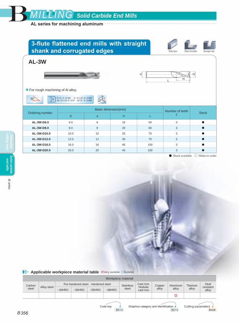
● For rough machining of Al alloy.
D≤6 0~-0.048 6<D≤10 0~-0.058 10<D≤18 0~-0.07 18<D 0~-0.084D
Workpiece material
Carbon steel Alloy steel
Pre-hardened steel、Hardened steel Stainless steel
Cast iron, Nodular cast iron
Copper alloy
Aluminum alloy
Titanium alloy
Heat resistant
alloy~40HRC ~50HRC ~55HRC ~68HRC
◎
AL-3W
Side face Step shoulder Straight slot
Applicable workpiece material table ◎Very suitable ○Suitable
Code key Cutting parametersGraphics category and identificationB213 B428B214
3-flute flattened end mills with straight shank and corrugated edges
B
B 356
Solid Carbide End MillsMILLINGMILLING
Indexable m
illing toolsSolid carbide
end mills
AL series for machining aluminum
AL series
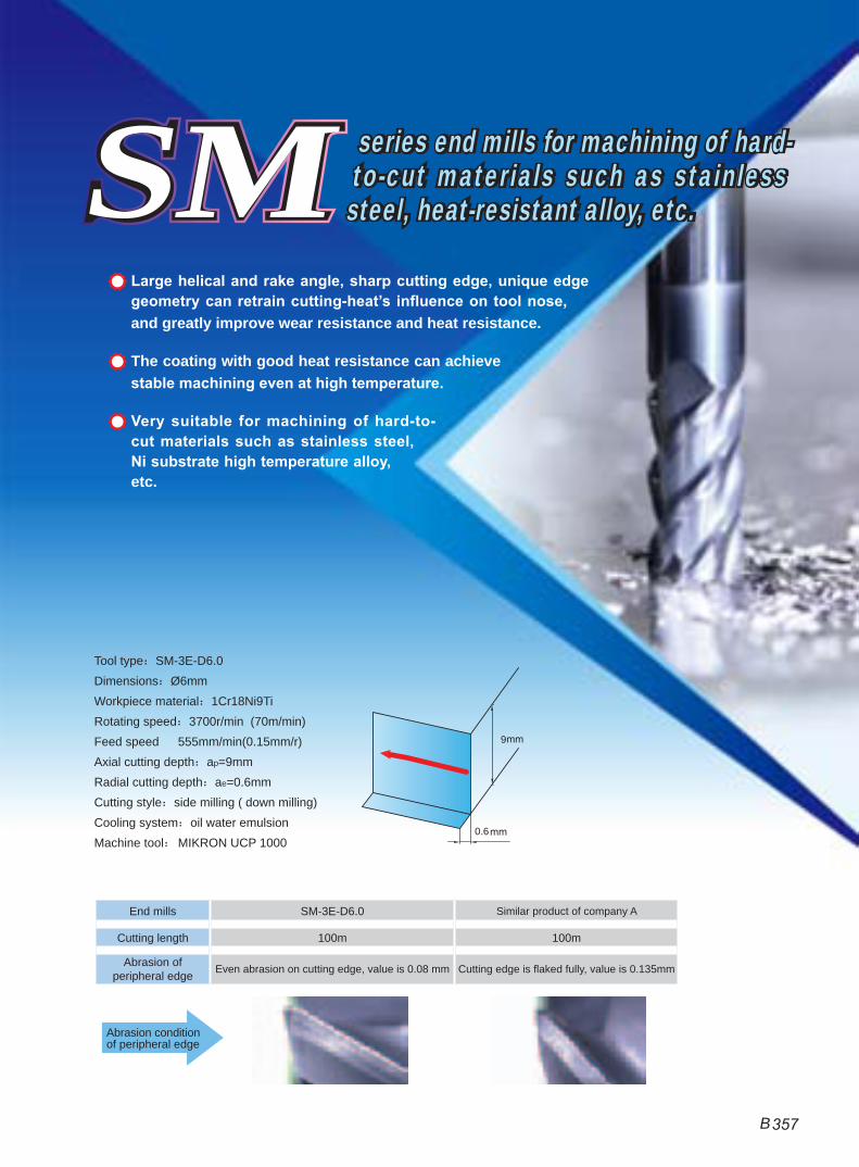
End mills SM-3E-D6.0 Similar product of company A
Cutting length 100m 100m
Abrasion of peripheral edge Even abrasion on cutting edge, value is 0.08 mm Cutting edge is flaked fully, value is 0.135mm
Abrasion condition of peripheral edge
Large helical and rake angle, sharp cutting edge, unique edge geometry can retrain cutting-heat’s influence on tool nose, and greatly improve wear resistance and heat resistance.
The coating with good heat resistance can achieve stable machining even at high temperature.
Very suitable for machining of hard-to-cut materials such as stainless steel, Ni substrate high temperature alloy, etc.
9
0.6
SMSM
Tool type:SM-3E-D6.0Dimensions:Ø6mmWorkpiece material:1Cr18Ni9TiRotating speed:3700r/min (70m/min)Feed speed 555mm/min(0.15mm/r)Axial cutting depth:ap=9mmRadial cutting depth:ae=0.6mmCutting style:side milling ( down milling)Cooling system:oil water emulsionMachine tool: MIKRON UCP 1000
series end mills for machining of hard-to-cut materials such as stainless steel, heat-resistant alloy, etc.
B 357
Workpiece material
Carbon steel Alloy steel
Pre-hardened steel、Hardened steel Stainless steel
Cast iron, Nodular cast iron
Copper alloy
Aluminum alloy
Titanium alloy
Heat resistant
alloy~40HRC ~50HRC ~55HRC ~68HRC
◎ ◎ ◎
Ordering numberBasic dimension(mm) Number of
teethZ
Geometry StockD d H L
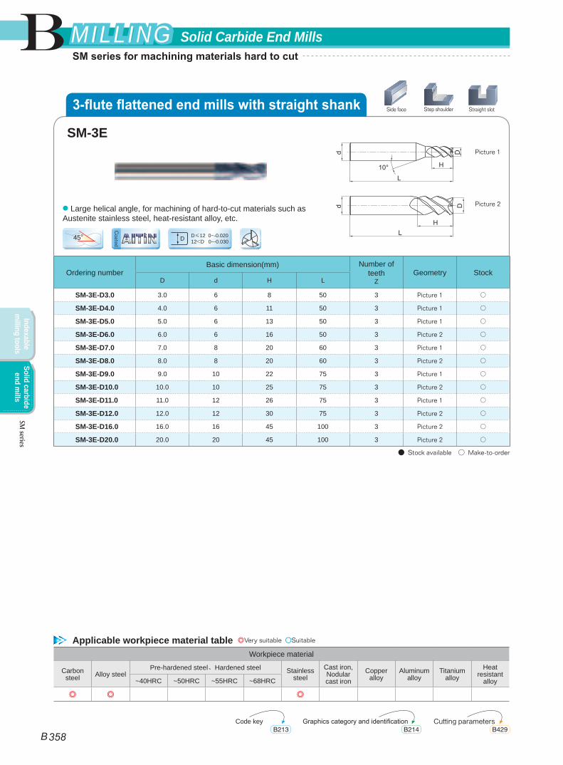
SM-3E-D3.0 3.0 6 8 50 3 Picture 1 ○
SM-3E-D4.0 4.0 6 11 50 3 Picture 1 ○
SM-3E-D5.0 5.0 6 13 50 3 Picture 1 ○
SM-3E-D6.0 6.0 6 16 50 3 Picture 2 ○
SM-3E-D7.0 7.0 8 20 60 3 Picture 1 ○
SM-3E-D8.0 8.0 8 20 60 3 Picture 2 ○
SM-3E-D9.0 9.0 10 22 75 3 Picture 1 ○
SM-3E-D10.0 10.0 10 25 75 3 Picture 2 ○
SM-3E-D11.0 11.0 12 26 75 3 Picture 1 ○
SM-3E-D12.0 12.0 12 30 75 3 Picture 2 ○
SM-3E-D16.0 16.0 16 45 100 3 Picture 2 ○
SM-3E-D20.0 20.0 20 45 100 3 Picture 2 ○
● Stock available ○ Make-to-order
D≤12 0~-0.02012<D 0~-0.030D45o
Picture 1
Picture 2● Large helical angle, for machining of hard-to-cut materials such as Austenite stainless steel, heat-resistant alloy, etc.
SM-3E
AITiN
Side face Step shoulder Straight slot
Coated
3-flute flattened end mills with straight shank
Applicable workpiece material table ◎Very suitable ○Suitable
Code key Cutting parametersGraphics category and identificationB213 B429B214
B
B 358
Solid Carbide End MillsMILLINGMILLING
Indexable m
illing toolsSolid carbide
end mills
SM series for machining materials hard to cut
SM series
Workpiece material
Carbon steel Alloy steel
Pre-hardened steel、Hardened steel Stainless steel
Cast iron, Nodular cast iron
Copper alloy
Aluminum alloy
Titanium alloy
Heat resistant
alloy~40HRC ~50HRC ~55HRC ~68HRC
◎ ◎ ◎
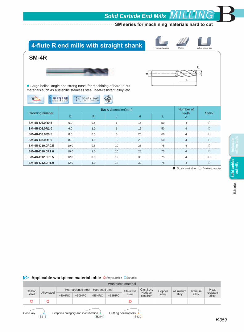
Ordering numberBasic dimension(mm) Number of
teethZ
StockD R d H L
SM-4R-D6.0R0.5 6.0 0.5 6 16 50 4 ○
SM-4R-D6.0R1.0 6.0 1.0 6 16 50 4 ○
SM-4R-D8.0R0.5 8.0 0.5 8 20 60 4 ○
SM-4R-D8.0R1.0 8.0 1.0 8 20 60 4 ○
SM-4R-D10.0R0.5 10.0 0.5 10 25 75 4 ○
SM-4R-D10.0R1.0 10.0 1.0 10 25 75 4 ○
SM-4R-D12.0R0.5 12.0 0.5 12 30 75 4 ○
SM-4R-D12.0R1.0 12.0 1.0 12 30 75 4 ○
● Stock available ○ Make-to-order
D≤12 0~-0.02012<D 0~-0.030D45o
● Large helical angle and strong nose, for machining of hard-to-cut materials such as austenitic stainless steel, heat-resistant alloy, etc.
SM-4R
Coated AITiN
ProfileRadius shoulder Radius corner slot
Applicable workpiece material table ◎Very suitable ○Suitable
Code key Cutting parametersGraphics category and identificationB213 B430B214
4-flute R end mills with straight shank
B
B 359
Solid Carbide End Mills MILLINGMILLING
Inde
xabl
e m
illin
g to
ols
Solid
car
bide
en
d m
ills
SM series for machining materials hard to cut
SM se
ries
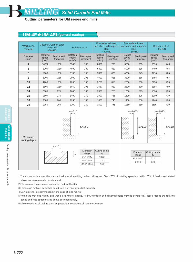
Workpiece material
Cast iron, Carbon steel, Alloy steel ~30HRC
Stainless steel
Pre-hardened steel, quenched and tempered
steel ~40HRC
Pre-hardened steel, quenched and tempered
steel ~50HRC
Hardened steel ~55HRC
Diameter(mm)
Rotating speed(min-1)
Feed speed(mm/min)
Rotating speed(min-1)
Feed speed(mm/min)
Rotating speed(min-1)
Feed speed(mm/min)
Rotating speed(min-1)
Feed speed(mm/min)
Rotating speed(min-1)
Feed speed(mm/min)
4 10800 1000 5500 180 8000 770 6500 605 5570 440
5 8200 1050 4500 180 6400 810 5000 635 4460 465
6 7000 1080 3700 195 5300 825 4200 645 3710 465
8 5200 1065 2800 195 4000 815 3200 665 2785 485
10 4200 1050 2200 195 3200 810 2500 630 2230 450
12 3500 1050 1850 195 2650 810 2100 630 1855 450
14 3000 975 1600 180 2300 755 1800 595 1590 430
16 2600 975 1400 170 2000 755 1600 595 1390 430
18 2300 960 1250 150 1800 745 1400 580 1240 420
20 2050 960 1100 150 1600 745 1250 580 1115 420
Maximum cutting depth
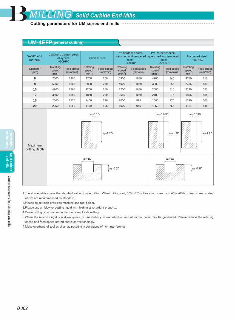
1.The above table shows the standard value of side milling. When milling slot, 50%~70% of rotating speed and 40%~60% of feed speed stated
above are recommended as standard.
2.Please select high-precision machine and tool holder.
3.Please use air blow or cutting liquid with high mist retardant property.
4.Down milling is recommended in the case of side milling.
5.When the machine rigidity and workpiece fixture stability is low, vibration and abnormal noise may be generated. Please reduce the rotating
speed and feed speed stated above correspondingly.
6.Make overhang of tool as short as possible in conditions of non-interference.
Diameter range
Cutting depth ap
Ø1≤D<Ø3 0.15D
Ø3≤D<Ø6 0.3D
Ø6≤D<Ø20 0.5D
Diameter range
Cutting depth ap
Ø1≤D<Ø3 0.1D
Ø3≤D 0.2D
ae=1D
ap
ae=0.1D
ap=1.5D
ae=0.05D
ap=1.5D
ae=0.03D
ap=1.5D
Cutting parameters for UM
series end mills
UM-4E★UM-4EL(general cutting)
B
B 360
Solid Carbide End MillsMILLINGMILLING
Indexable m
illing toolsSolid carbide
end mills
Cutting parameters for UM series end mills
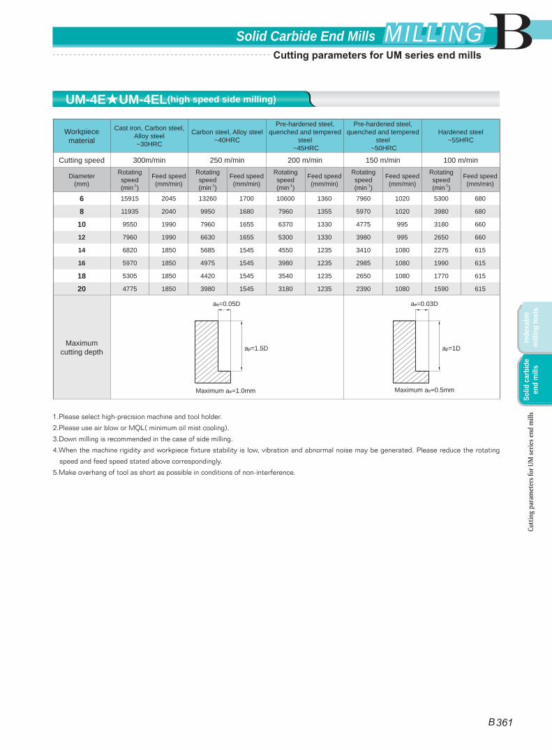
Workpiece material
Cast iron, Carbon steel, Alloy steel ~30HRC
Carbon steel, Alloy steel ~40HRC
Pre-hardened steel, quenched and tempered
steel ~45HRC
Pre-hardened steel, quenched and tempered
steel ~50HRC
Hardened steel~55HRC
Cutting speed 300m/min 250 m/min 200 m/min 150 m/min 100 m/min
Diameter(mm)
Rotating speed(min-1)
Feed speed(mm/min)
Rotating speed(min-1)
Feed speed(mm/min)
Rotating speed(min-1)
Feed speed(mm/min)
Rotating speed(min-1)
Feed speed(mm/min)
Rotating speed(min-1)
Feed speed(mm/min)
6 15915 2045 13260 1700 10600 1360 7960 1020 5300 680
8 11935 2040 9950 1680 7960 1355 5970 1020 3980 680
10 9550 1990 7960 1655 6370 1330 4775 995 3180 660
12 7960 1990 6630 1655 5300 1330 3980 995 2650 660
14 6820 1850 5685 1545 4550 1235 3410 1080 2275 615
16 5970 1850 4975 1545 3980 1235 2985 1080 1990 615
18 5305 1850 4420 1545 3540 1235 2650 1080 1770 615
20 4775 1850 3980 1545 3180 1235 2390 1080 1590 615
Maximum cutting depth
1.Please select high-precision machine and tool holder.
2.Please use air blow or MQL( minimum oil mist cooling).
3.Down milling is recommended in the case of side milling.
4.When the machine rigidity and workpiece fixture stability is low, vibration and abnormal noise may be generated. Please reduce the rotating
speed and feed speed stated above correspondingly.
5.Make overhang of tool as short as possible in conditions of non-interference.
ae=0.05D
ap=1.5D
Maximum ae=1.0mm
ae=0.03D
ap=1D
Maximum ae=0.5mm
Cutt
ing
para
met
ers f
or U
M se
ries e
nd m
ills
UM-4E★UM-4EL(high speed side milling)
B
B 361
Solid Carbide End Mills MILLINGMILLING
Inde
xabl
e m
illin
g to
ols
Solid
car
bide
en
d m
ills
Cutting parameters for UM series end mills
Workpiece material
Cast iron, Carbon steel, Alloy steel ~30HRC
Stainless steel
Pre-hardened steel, quenched and tempered
steel ~40HRC
Pre-hardened steel, quenched and tempered
steel ~50HRC
Hardened steel ~55HRC
Diameter(mm)
Rotating speed(min-1)
Feed speed(mm/min)
Rotating speed(min-1)
Feed speed(mm/min)
Rotating speed(min-1)
Feed speed(mm/min)
Rotating speed(min-1)
Feed speed(mm/min)
Rotating speed(min-1)
Feed speed(mm/min)
6 7000 1400 3700 250 5300 1080 4200 845 3710 610
8 5200 1385 2800 250 4000 1060 3200 865 2785 630
10 4200 1365 2200 250 3200 1050 2500 815 2230 585
12 3500 1365 1850 250 2650 1050 2100 815 1855 585
16 2600 1270 1400 220 2000 975 1600 770 1390 560
20 2050 1255 1100 195 1600 965 1250 755 1115 545
Maximum cutting depth
1.The above table shows the standard value of side milling. When milling slot, 50%~70% of rotating speed and 40%~60% of feed speed stated
above are recommended as standard.
2.Please select high-precision machine and tool holder.
3.Please use air blow or cutting liquid with high mist retardant property.
4.Down milling is recommended in the case of side milling.
5.When the machine rigidity and workpiece fixture stability is low, vibration and abnormal noise may be generated. Please reduce the rotating
speed and feed speed stated above correspondingly.
6.Make overhang of tool as short as possible in conditions of non-interference.
ae=1D
ap=0.5D
ae=1D
ap=0.2D
ae=0.1D
ap=1.2D
ae=0.05D
ap=1.2D
ae=0.03D
ap=1.2D
UM-4EFP(general cutting)
B
B 362
Solid Carbide End MillsMILLINGMILLING
Indexable m
illing toolsSolid carbide
end mills
Cutting parameters for UM
series end mills
Cutting parameters for UM series end mills
Workpiece material
Cast iron, Carbon steel, Alloy steel ~30HRC
Carbon steel, Alloy steel ~40HRC
Pre-hardened steel, quenched and tempered
steel ~45HRC
Pre-hardened steel, quenched and tempered
steel ~50HRC
Hardened steel~55HRC
Cutting speed 300m/min 250 m/min 200 m/min 150 m/min 100 m/min
Diameter(mm)
Rotating speed(min-1)
Feed speed(mm/min)
Rotating speed(min-1)
Feed speed(mm/min)
Rotating speed(min-1)
Feed speed(mm/min)
Rotating speed(min-1)
Feed speed(mm/min)
Rotating speed(min-1)
Feed speed(mm/min)
6 15915 2655 13260 2210 10600 1770 7960 1325 5300 885
8 11935 2650 9950 2180 7960 1760 5970 1295 3980 885
10 9550 2590 7960 2150 6370 1730 4775 1295 3180 855
12 7960 2590 6630 2150 5300 1730 3980 1400 2650 855
16 5970 2410 4975 2015 3980 1605 2985 1400 1990 800
20 4775 2410 3980 2375 3180 1605 2390 1325 1590 800
Maximum cutting depth
1.Please select high-precision machine and tool holder.
2.Please use air blow or MQL( minimum oil mist cooling).
3.Down milling is recommended in the case of side milling.
4.When the machine rigidity and workpiece fixture stability is low, vibration and abnormal noise may be generated. Please reduce the rotating
speed and feed speed stated above correspondingly.
5.Make overhang of tool as short as possible in conditions of non-interference.
ae=0.05D
ap=1.2D
Maximum ae=1.0mm
ae=0.03D
ap=1D
Maximum ae=0.5mm
UM-4EFP(high speed side milling)
B
B 363
Solid Carbide End Mills MILLINGMILLING
Inde
xabl
e m
illin
g to
ols
Solid
car
bide
en
d m
ills
Cutt
ing
para
met
ers f
or U
M se
ries e
nd m
ills
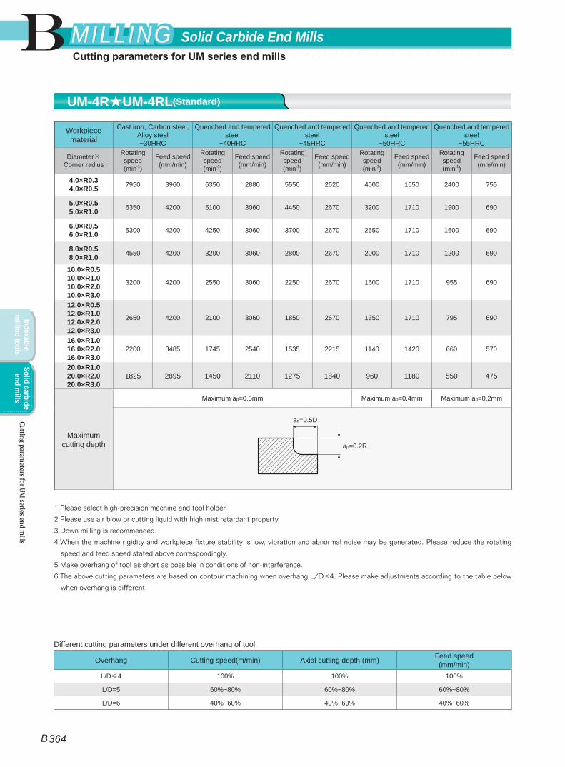
Cutting parameters for UM series end mills
Workpiece material
Cast iron, Carbon steel, Alloy steel ~30HRC
Quenched and tempered steel
~40HRC
Quenched and tempered steel
~45HRC
Quenched and tempered steel
~50HRC
Quenched and tempered steel
~55HRC
Diameter×Corner radius
Rotating speed(min-1)
Feed speed(mm/min)
Rotating speed(min-1)
Feed speed(mm/min)
Rotating speed(min-1)
Feed speed(mm/min)
Rotating speed(min-1)
Feed speed(mm/min)
Rotating speed(min-1)
Feed speed(mm/min)
4.0×R0.34.0×R0.5 7950 3960 6350 2880 5550 2520 4000 1650 2400 755
5.0×R0.55.0×R1.0 6350 4200 5100 3060 4450 2670 3200 1710 1900 690
6.0×R0.56.0×R1.0 5300 4200 4250 3060 3700 2670 2650 1710 1600 690
8.0×R0.58.0×R1.0 4550 4200 3200 3060 2800 2670 2000 1710 1200 690
10.0×R0.510.0×R1.010.0×R2.010.0×R3.0
3200 4200 2550 3060 2250 2670 1600 1710 955 690
12.0×R0.512.0×R1.012.0×R2.012.0×R3.0
2650 4200 2100 3060 1850 2670 1350 1710 795 690
16.0×R1.016.0×R2.016.0×R3.0
2200 3485 1745 2540 1535 2215 1140 1420 660 570
20.0×R1.020.0×R2.020.0×R3.0
1825 2895 1450 2110 1275 1840 960 1180 550 475
Maximum cutting depth
Maximum ap=0.5mm Maximum ap=0.4mm Maximum ap=0.2mm
1.Please select high-precision machine and tool holder.
2.Please use air blow or cutting liquid with high mist retardant property.
3.Down milling is recommended.
4.When the machine rigidity and workpiece fixture stability is low, vibration and abnormal noise may be generated. Please reduce the rotating
speed and feed speed stated above correspondingly.
5.Make overhang of tool as short as possible in conditions of non-interference.
6.The above cutting parameters are based on contour machining when overhang L/D≤4. Please make adjustments according to the table below
when overhang is different.
ae=0.5D
ap=0.2R
Different cutting parameters under different overhang of tool:
Overhang Cutting speed(m/min) Axial cutting depth (mm) Feed speed(mm/min)
L/D≤4 100% 100% 100%
L/D=5 60%~80% 60%~80% 60%~80%
L/D=6 40%~60% 40%~60% 40%~60%
UM-4R★UM-4RL(Standard)
B
B 364
Solid Carbide End MillsMILLINGMILLING
Indexable m
illing toolsSolid carbide
end mills
Cutting parameters for UM
series end mills
Cutting parameters for UM series end mills
Workpiece material
Cast iron, Carbon steel, Alloy steel ~30HRC
Quenched and tempered steel
~40HRC
Quenched and tempered steel
~45HRC
Quenched and tempered steel
~50HRC
Quenched and tempered steel
~55HRC
Diameter×Corner radius
Rotating speed(min-1)
Feed speed(mm/min)
Rotating speed(min-1)
Feed speed(mm/min)
Rotating speed(min-1)
Feed speed(mm/min)
Rotating speed(min-1)
Feed speed(mm/min)
Rotating speed(min-1)
Feed speed(mm/min)
4.0×R0.34.0×R0.5 16000 7800 16000 7200 12000 5400 12000 4920 7950 2130
5.0×R0.55.0×R1.0 12500 8400 12500 7500 9550 5730 9550 5160 6350 2280
6.0×R0.56.0×R1.0 10600 8400 10600 7620 7950 5730 7950 5160 5300 2280
8.0×R0.58.0×R1.0 7950 8400 7950 7620 5950 5730 5950 5160 4000 2280
10.0×R0.510.0×R1.010.0×R2.010.0×R3.0
6350 8400 6350 7620 4750 5730 4750 5160 3200 2280
12.0×R0.512.0×R1.012.0×R2.012.0×R3.0
5300 8400 5300 7620 4000 5730 4000 5160 2650 2280
16.0×R1.016.0×R2.016.0×R3.0
3980 6970 3980 6320 2985 4755 2985 4280 1990 1890
20.0×R1.020.0×R2.020.0×R3.0
3185 5785 3185 5245 2385 3945 2385 3550 1590 1570
Maximum cutting depth
Maximum ap=0.4mm Maximum ap=0.2mm Maximum ap=0.1mm
1.Please select high-precision machine and tool holder.
2.Please use air blow or cutting liquid with high mist retardant property.
3.Down milling is recommended.
4.When the machine rigidity and workpiece fixture stability is low, vibration and abnormal noise may be generated. Please reduce the rotating
speed and feed speed stated above correspondingly.
5.Make overhang of tool as short as possible in conditions of non-interference.
6.The above cutting parameters are based on contour machining when overhang L/D≤4. Please make adjustments according to the table below
when overhang is different.
ae=0.3D
ap=0.2R
Different cutting parameters under different overhang of tool:
Ratio of neck length to diameter Cutting speed(m/min) Axial cutting depth(mm) Feed speed(mm/min)
L/D≤4 100% 100% 100%
L/D=5 60%~80% 60%~80% 60%~80%
L/D=6 40%~60% 40%~60% 40%~60%
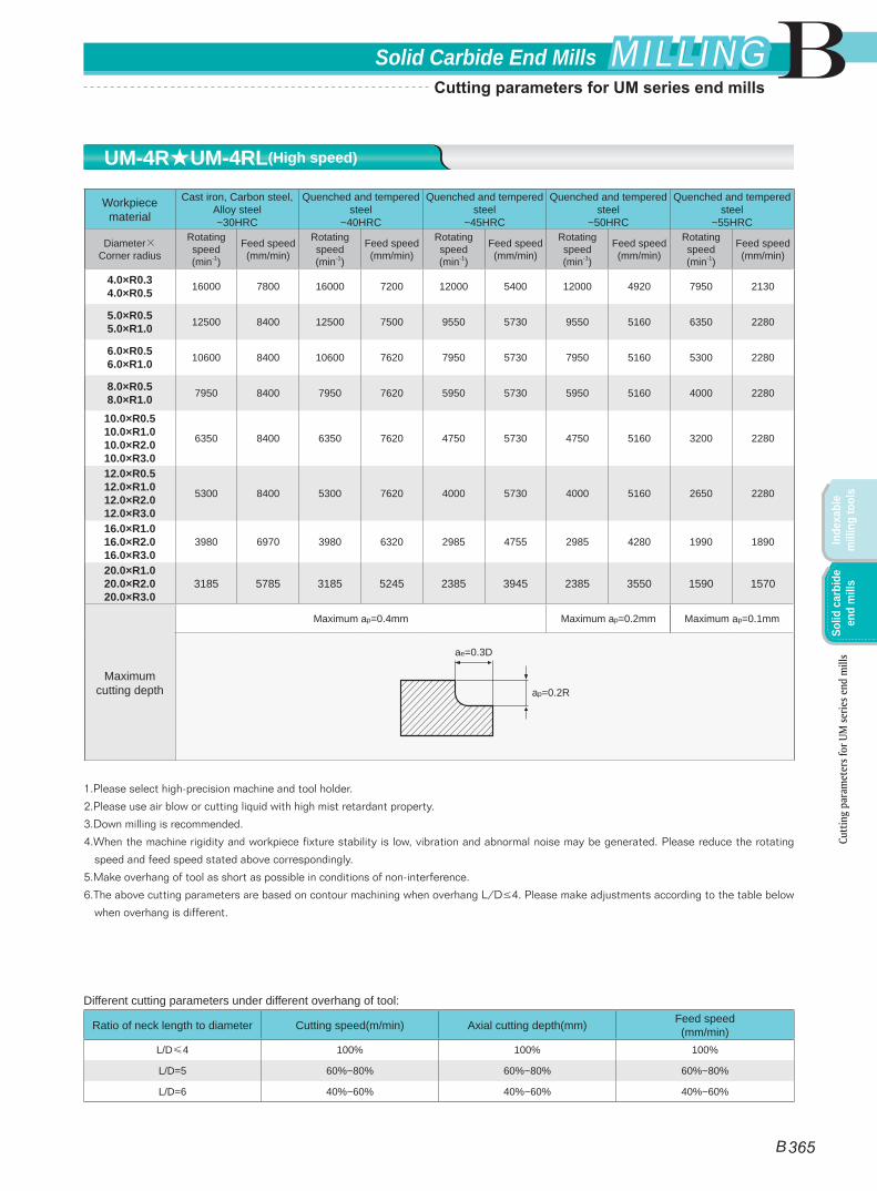
UM-4R★UM-4RL(High speed)
B
B 365
Solid Carbide End Mills MILLINGMILLING
Inde
xabl
e m
illin
g to
ols
Solid
car
bide
en
d m
ills
Cutt
ing
para
met
ers f
or U
M se
ries e
nd m
ills
Cutting parameters for UM series end mills
Workpiece material
Cast iron, Carbon steel, Alloy steel ~30HRC
Stainless steel
Pre-hardened steel, quenched and tempered
steel ~40HRC
Pre-hardened steel, quenched and tempered
steel ~50HRC
Hardened steel ~55HRC
Diameter(mm)
Rotating speed(min-1)
Feed speed(mm/min)
Rotating speed(min-1)
Feed speed(mm/min)
Rotating speed(min-1)
Feed speed(mm/min)
Rotating speed(min-1)
Feed speed(mm/min)
Rotating speed(min-1)
Feed speed(mm/min)
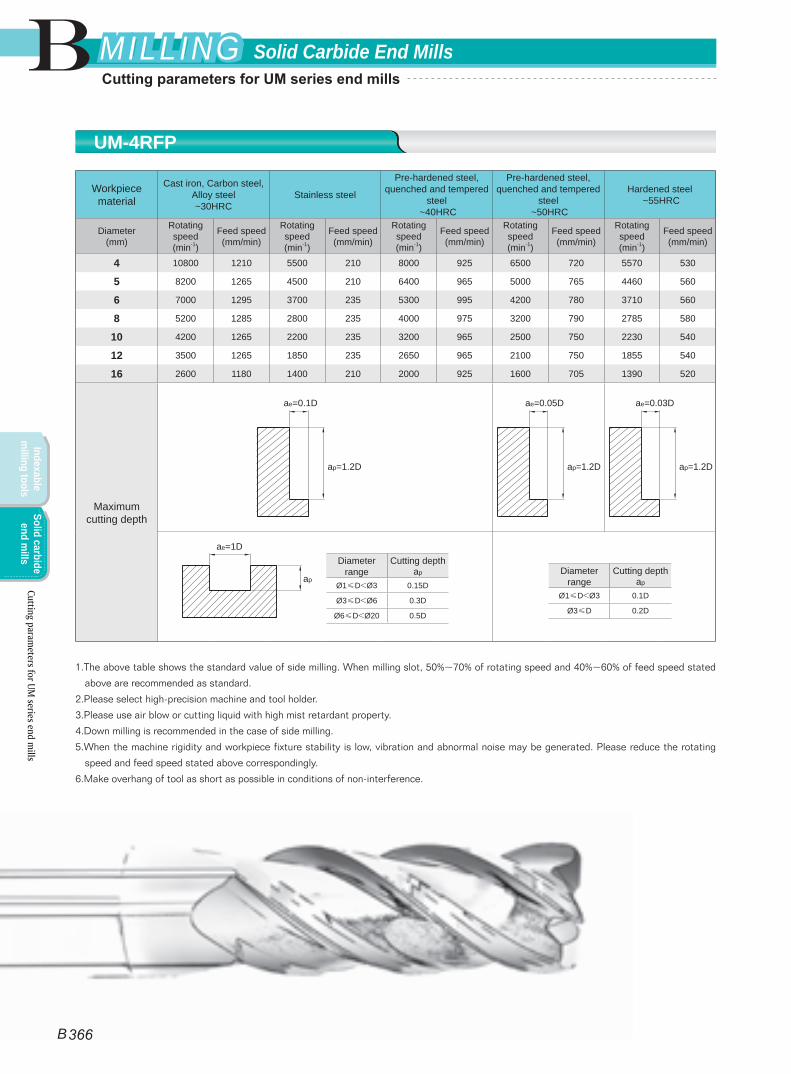
4 10800 1210 5500 210 8000 925 6500 720 5570 530
5 8200 1265 4500 210 6400 965 5000 765 4460 560
6 7000 1295 3700 235 5300 995 4200 780 3710 560
8 5200 1285 2800 235 4000 975 3200 790 2785 580
10 4200 1265 2200 235 3200 965 2500 750 2230 540
12 3500 1265 1850 235 2650 965 2100 750 1855 540
16 2600 1180 1400 210 2000 925 1600 705 1390 520
Maximum cutting depth
1.The above table shows the standard value of side milling. When milling slot, 50%~70% of rotating speed and 40%~60% of feed speed stated
above are recommended as standard.
2.Please select high-precision machine and tool holder.
3.Please use air blow or cutting liquid with high mist retardant property.
4.Down milling is recommended in the case of side milling.
5.When the machine rigidity and workpiece fixture stability is low, vibration and abnormal noise may be generated. Please reduce the rotating
speed and feed speed stated above correspondingly.
6.Make overhang of tool as short as possible in conditions of non-interference.
Diameter range
Cutting depth ap
Ø1≤D<Ø3 0.15D
Ø3≤D<Ø6 0.3D
Ø6≤D<Ø20 0.5D
Diameter range
Cutting depth ap
Ø1≤D<Ø3 0.1D
Ø3≤D 0.2D
ae=1D
ap
ae=0.1D
ap=1.2D
ae=0.05D
ap=1.2D
ae=0.03D
ap=1.2D
UM-4RFP
B
B 366
Solid Carbide End MillsMILLINGMILLING
Indexable m
illing toolsSolid carbide
end mills
Cutting parameters for UM
series end mills
Cutting parameters for UM series end mills
Workpiece material
Cast iron, Carbon steel, Alloy steel ~30HRC
Stainless steel
Pre-hardened steel, quenched and tempered
steel ~40HRC
Pre-hardened steel, quenched and tempered
steel ~50HRC
Hardened steel ~55HRC
Diameter(mm)
Rotating speed(min-1)
Feed speed(mm/min)
Rotating speed(min-1)
Feed speed(mm/min)
Rotating speed(min-1)
Feed speed(mm/min)
Rotating speed(min-1)
Feed speed(mm/min)
Rotating speed(min-1)
Feed speed(mm/min)
1 20000 200 20000 60 20000 165 20000 120 20000 90
2 15000 320 11150 85 15000 285 13000 180 11140 130
3 14000 545 7500 120 10600 420 8500 330 7430 240
4 10800 560 5500 135 8000 425 6500 335 5570 245
5 8200 585 4500 135 6400 445 5000 355 4460 260
6 7000 600 3700 140 5300 465 4200 360 3710 260
8 5200 595 2800 140 4000 455 3200 365 2785 270
10 4200 585 2200 140 3200 445 2500 350 2230 250
12 3500 585 1850 140 2650 445 2100 350 1855 250
14 3000 545 1600 135 2300 420 1800 330 1590 240
16 2600 545 1400 120 2000 420 1600 330 1390 240
18 2300 535 1250 120 1800 415 1400 325 1240 235
20 2050 535 1100 120 1600 415 1250 325 1115 235
Maximum cutting depth
1.The above table shows the standard value of side milling. When milling slot, 50%~70% of rotating speed and 40%~60% of feed speed stated
above are recommended as standard.
2.Please select high-precision machine and tool holder.
3.Please use air blow or cutting liquid with high mist retardant property.
4.Down milling is recommended in the case of side milling.
5.When the machine rigidity and workpiece fixture stability is low, vibration and abnormal noise may be generated. Please reduce the rotating
speed and feed speed stated above correspondingly.
6.Make overhang of tool as short as possible in conditions of non-interference.
Diameter range
Cutting depth ap
Ø1≤D<Ø3 0.15D
Ø3≤D<Ø6 0.3D
Ø6≤D<Ø20 0.5D
Diameter range
Cutting depth ap
Ø1≤D<Ø3 0.1D
Ø3≤D 0.2D
ae=1D
ap
ae=0.1D
ap=1.5D
ae=0.05D
ap=1.5D
ae=0.03D
ap=1.5D
PML-2E★PM-2E★PML-2EL★PM-2EL
Cutt
ing
para
met
ers f
or P
ML/
PM se
ries e
nd m
ills
B
B 367
Solid Carbide End Mills MILLINGMILLING
Inde
xabl
e m
illin
g to
ols
Solid
car
bide
en
d m
ills
Cutting parameters for PML/PM series end mills
Workpiece material
Cast iron, Carbon steel, Alloy steel ~30HRC
Stainless steel
Pre-hardened steel, quenched and tempered
steel ~40HRC
Pre-hardened steel, quenched and tempered
steel ~50HRC
Hardened steel ~55HRC
Diameter(mm)
Rotating speed(min-1)
Feed speed(mm/min)
Rotating speed(min-1)
Feed speed(mm/min)
Rotating speed(min-1)
Feed speed(mm/min)
Rotating speed(min-1)
Feed speed(mm/min)
Rotating speed(min-1)
Feed speed(mm/min)
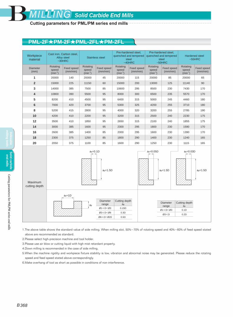
1 20000 140 20000 45 20000 115 20000 85 20000 65
2 15000 225 11150 60 15000 200 13000 125 11140 90
3 14000 385 7500 85 10600 295 8500 230 7430 170
4 10800 390 5500 95 8000 300 6500 235 5570 170
5 8200 410 4500 95 6400 315 5000 245 4460 180
6 7000 420 3700 95 5300 325 4200 255 3710 180
8 5200 415 2800 95 4000 320 3200 255 2785 190
10 4200 410 2200 95 3200 315 2500 240 2230 175
12 3500 410 1850 95 2650 315 2100 240 1855 175
14 3000 385 1600 95 2300 295 1800 230 1590 170
16 2600 385 1400 85 2000 295 1600 230 1390 170
18 2300 375 1250 85 1800 290 1400 230 1240 165
20 2050 375 1100 85 1600 290 1250 230 1115 165
Maximum cutting depth
1.The above table shows the standard value of side milling. When milling slot, 50%~70% of rotating speed and 40%~60% of feed speed stated
above are recommended as standard.
2.Please select high-precision machine and tool holder.
3.Please use air blow or cutting liquid with high mist retardant property.
4.Down milling is recommended in the case of side milling.
5.When the machine rigidity and workpiece fixture stability is low, vibration and abnormal noise may be generated. Please reduce the rotating
speed and feed speed stated above correspondingly.
6.Make overhang of tool as short as possible in conditions of non-interference.
Diameter range
Cutting depth ap
Ø1≤D<Ø3 0.15D
Ø3≤D<Ø6 0.3D
Ø6≤D<Ø20 0.5D
ae=1D
apDiameter
rangeCutting depth
ap
Ø1≤D<Ø3 0.1D
Ø3≤D 0.2D
ae=0.1D
ap=1.5D
ae=0.05D
ap=1.5D
ae=0.03D
ap=1.5D
PML-2F★PM-2F★PML-2FL★PM-2FL
Cutting parameters for PM
L/PM series end m
ills
B
B 368
Solid Carbide End MillsMILLINGMILLING
Indexable m
illing toolsSolid carbide
end mills
Cutting parameters for PML/PM series end mills
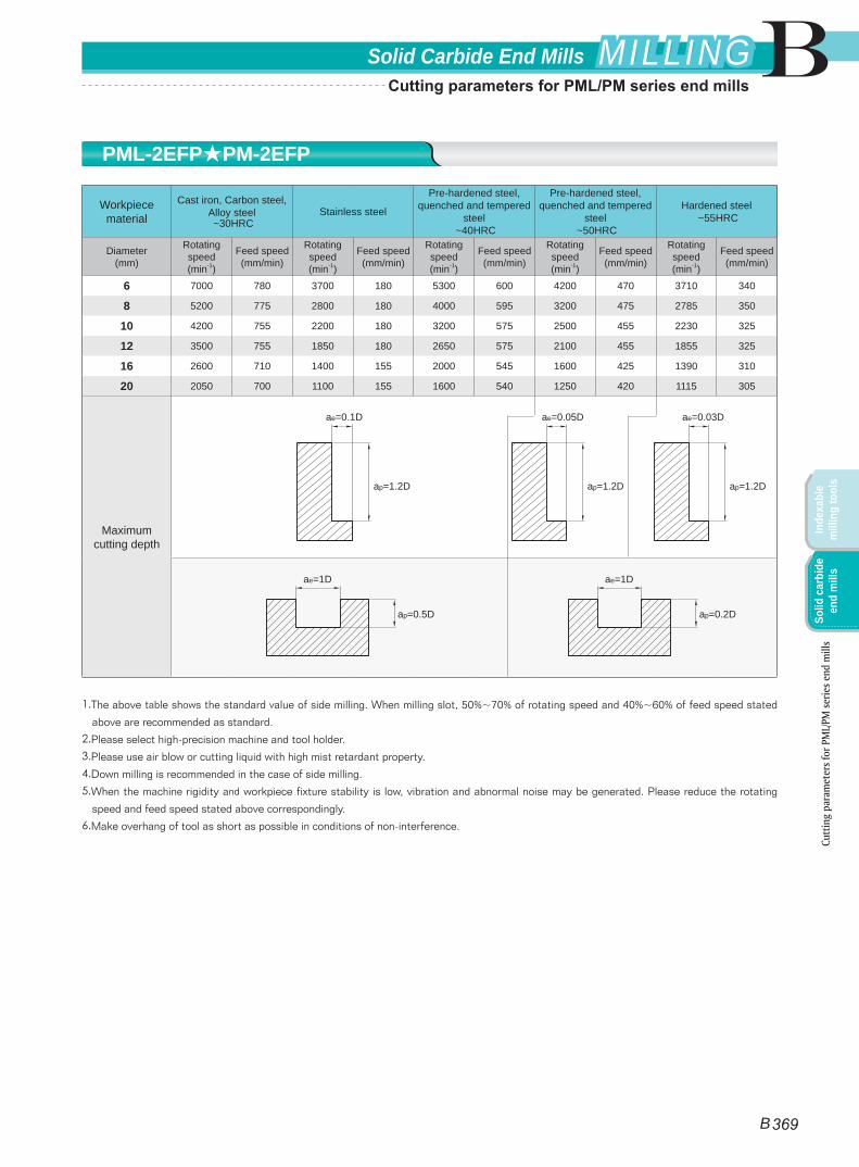
Workpiece material
Cast iron, Carbon steel, Alloy steel ~30HRC
Stainless steel
Pre-hardened steel, quenched and tempered
steel ~40HRC
Pre-hardened steel, quenched and tempered
steel ~50HRC
Hardened steel ~55HRC
Diameter(mm)
Rotating speed(min-1)
Feed speed(mm/min)
Rotating speed(min-1)
Feed speed(mm/min)
Rotating speed(min-1)
Feed speed(mm/min)
Rotating speed(min-1)
Feed speed(mm/min)
Rotating speed(min-1)
Feed speed(mm/min)
6 7000 780 3700 180 5300 600 4200 470 3710 340
8 5200 775 2800 180 4000 595 3200 475 2785 350
10 4200 755 2200 180 3200 575 2500 455 2230 325
12 3500 755 1850 180 2650 575 2100 455 1855 325
16 2600 710 1400 155 2000 545 1600 425 1390 310
20 2050 700 1100 155 1600 540 1250 420 1115 305
Maximum cutting depth
1.The above table shows the standard value of side milling. When milling slot, 50%~70% of rotating speed and 40%~60% of feed speed stated
above are recommended as standard.
2.Please select high-precision machine and tool holder.
3.Please use air blow or cutting liquid with high mist retardant property.
4.Down milling is recommended in the case of side milling.
5.When the machine rigidity and workpiece fixture stability is low, vibration and abnormal noise may be generated. Please reduce the rotating
speed and feed speed stated above correspondingly.
6.Make overhang of tool as short as possible in conditions of non-interference.
ae=1D
ap=0.5D
ae=1D
ap=0.2D
ae=0.1D
ap=1.2D
ae=0.05D
ap=1.2D
ae=0.03D
ap=1.2D
PML-2EFP★PM-2EFP
Cutt
ing
para
met
ers f
or P
ML/
PM se
ries e
nd m
ills
B
B 369
Solid Carbide End Mills MILLINGMILLING
Inde
xabl
e m
illin
g to
ols
Solid
car
bide
en
d m
ills
Cutting parameters for PML/PM series end mills
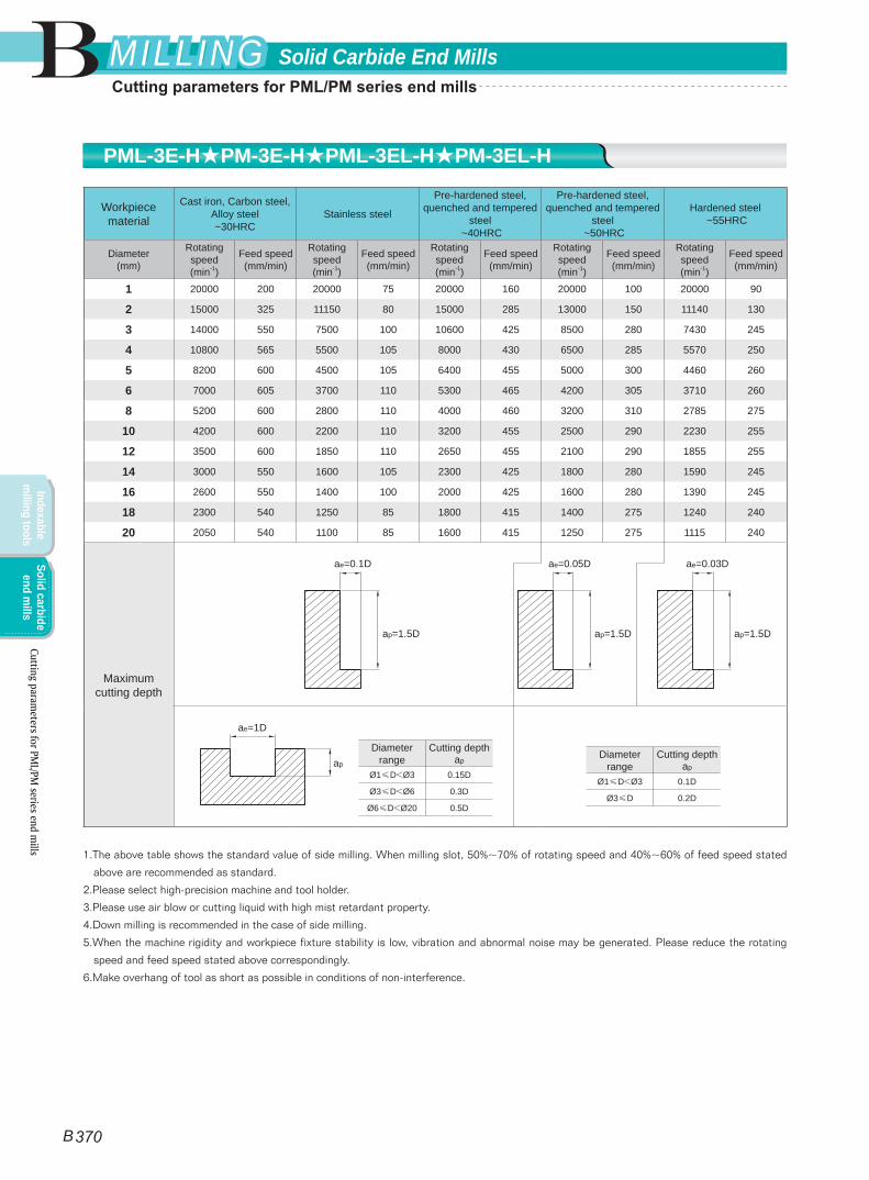
PML-3E-H★PM-3E-H★PML-3EL-H★PM-3EL-H
Workpiece material
Cast iron, Carbon steel, Alloy steel ~30HRC
Stainless steel
Pre-hardened steel, quenched and tempered
steel ~40HRC
Pre-hardened steel, quenched and tempered
steel ~50HRC
Hardened steel ~55HRC
Diameter(mm)
Rotating speed(min-1)
Feed speed(mm/min)
Rotating speed(min-1)
Feed speed(mm/min)
Rotating speed(min-1)
Feed speed(mm/min)
Rotating speed(min-1)
Feed speed(mm/min)
Rotating speed(min-1)
Feed speed(mm/min)
1 20000 200 20000 75 20000 160 20000 100 20000 90
2 15000 325 11150 80 15000 285 13000 150 11140 130
3 14000 550 7500 100 10600 425 8500 280 7430 245
4 10800 565 5500 105 8000 430 6500 285 5570 250
5 8200 600 4500 105 6400 455 5000 300 4460 260
6 7000 605 3700 110 5300 465 4200 305 3710 260
8 5200 600 2800 110 4000 460 3200 310 2785 275
10 4200 600 2200 110 3200 455 2500 290 2230 255
12 3500 600 1850 110 2650 455 2100 290 1855 255
14 3000 550 1600 105 2300 425 1800 280 1590 245
16 2600 550 1400 100 2000 425 1600 280 1390 245
18 2300 540 1250 85 1800 415 1400 275 1240 240
20 2050 540 1100 85 1600 415 1250 275 1115 240
Maximum cutting depth
1.The above table shows the standard value of side milling. When milling slot, 50%~70% of rotating speed and 40%~60% of feed speed stated
above are recommended as standard.
2.Please select high-precision machine and tool holder.
3.Please use air blow or cutting liquid with high mist retardant property.
4.Down milling is recommended in the case of side milling.
5.When the machine rigidity and workpiece fixture stability is low, vibration and abnormal noise may be generated. Please reduce the rotating
speed and feed speed stated above correspondingly.
6.Make overhang of tool as short as possible in conditions of non-interference.
Diameter range
Cutting depth ap
Ø1≤D<Ø3 0.15D
Ø3≤D<Ø6 0.3D
Ø6≤D<Ø20 0.5D
ae=1D
apDiameter
rangeCutting depth
ap
Ø1≤D<Ø3 0.1D
Ø3≤D 0.2D
ae=0.1D
ap=1.5D
ae=0.05D
ap=1.5D
ae=0.03D
ap=1.5D
Cutting parameters for PM
L/PM series end m
ills
B
B 370
Solid Carbide End MillsMILLINGMILLING
Indexable m
illing toolsSolid carbide
end mills
Cutting parameters for PML/PM series end mills
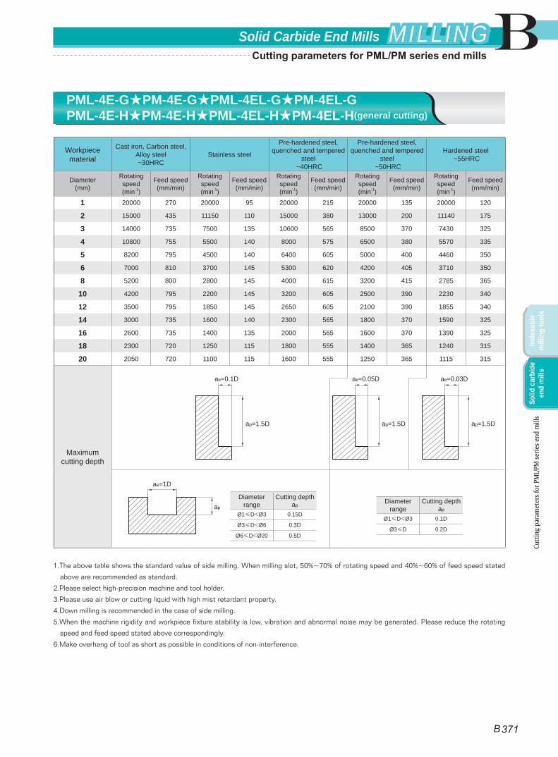
Workpiece material
Cast iron, Carbon steel, Alloy steel ~30HRC
Stainless steel
Pre-hardened steel, quenched and tempered
steel ~40HRC
Pre-hardened steel, quenched and tempered
steel ~50HRC
Hardened steel ~55HRC
Diameter(mm)
Rotating speed(min-1)
Feed speed(mm/min)
Rotating speed(min-1)
Feed speed(mm/min)
Rotating speed(min-1)
Feed speed(mm/min)
Rotating speed(min-1)
Feed speed(mm/min)
Rotating speed(min-1)
Feed speed(mm/min)
1 20000 270 20000 95 20000 215 20000 135 20000 120
2 15000 435 11150 110 15000 380 13000 200 11140 175
3 14000 735 7500 135 10600 565 8500 370 7430 325
4 10800 755 5500 140 8000 575 6500 380 5570 335
5 8200 795 4500 140 6400 605 5000 400 4460 350
6 7000 810 3700 145 5300 620 4200 405 3710 350
8 5200 800 2800 145 4000 615 3200 415 2785 365
10 4200 795 2200 145 3200 605 2500 390 2230 340
12 3500 795 1850 145 2650 605 2100 390 1855 340
14 3000 735 1600 140 2300 565 1800 370 1590 325
16 2600 735 1400 135 2000 565 1600 370 1390 325
18 2300 720 1250 115 1800 555 1400 365 1240 315
20 2050 720 1100 115 1600 555 1250 365 1115 315
Maximum cutting depth
1.The above table shows the standard value of side milling. When milling slot, 50%~70% of rotating speed and 40%~60% of feed speed stated
above are recommended as standard.
2.Please select high-precision machine and tool holder.
3.Please use air blow or cutting liquid with high mist retardant property.
4.Down milling is recommended in the case of side milling.
5.When the machine rigidity and workpiece fixture stability is low, vibration and abnormal noise may be generated. Please reduce the rotating
speed and feed speed stated above correspondingly.
6.Make overhang of tool as short as possible in conditions of non-interference.
Diameter range
Cutting depth ap
Ø1≤D<Ø3 0.15D
Ø3≤D<Ø6 0.3D
Ø6≤D<Ø20 0.5D
ae=1D
apDiameter
rangeCutting depth
ap
Ø1≤D<Ø3 0.1D
Ø3≤D 0.2D
ae=0.1D
ap=1.5D
ae=0.05D
ap=1.5D
ae=0.03D
ap=1.5D
PML-4E-G★PM-4E-G★PML-4EL-G★PM-4EL-GPML-4E-H★PM-4E-H★PML-4EL-H★PM-4EL-H(general cutting)
Cutt
ing
para
met
ers f
or P
ML/
PM se
ries e
nd m
ills
B
B 371
Solid Carbide End Mills MILLINGMILLING
Inde
xabl
e m
illin
g to
ols
Solid
car
bide
en
d m
ills
Cutting parameters for PML/PM series end mills
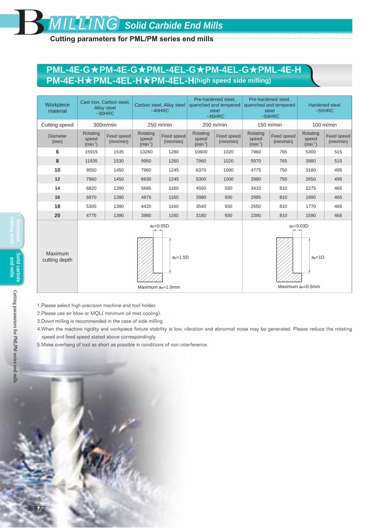
Workpiece material
Cast iron, Carbon steel, Alloy steel ~30HRC
Carbon steel, Alloy steel ~40HRC
Pre-hardened steel, quenched and tempered
steel ~45HRC
Pre-hardened steel, quenched and tempered
steel ~50HRC
Hardened steel~55HRC
Cutting speed 300m/min 250 m/min 200 m/min 150 m/min 100 m/min
Diameter(mm)
Rotating speed(min-1)
Feed speed(mm/min)
Rotating speed(min-1)
Feed speed(mm/min)
Rotating speed(min-1)
Feed speed(mm/min)
Rotating speed(min-1)
Feed speed(mm/min)
Rotating speed(min-1)
Feed speed(mm/min)
6 15915 1535 13260 1280 10600 1020 7960 765 5300 515
8 11935 1530 9950 1260 7960 1020 5970 765 3980 515
10 9550 1450 7960 1245 6370 1000 4775 750 3180 495
12 7960 1450 6630 1245 5300 1000 3980 750 2650 495
14 6820 1390 5685 1160 4550 930 3410 810 2275 465
16 5970 1390 4975 1160 3980 930 2985 810 1990 465
18 5305 1390 4420 1160 3540 930 2650 810 1770 465
20 4775 1390 3980 1160 3180 930 2390 810 1590 465
Maximum cutting depth
1.Please select high-precision machine and tool holder.
2.Please use air blow or MQL( minimum oil mist cooling).
3.Down milling is recommended in the case of side milling.
4.When the machine rigidity and workpiece fixture stability is low, vibration and abnormal noise may be generated. Please reduce the rotating
speed and feed speed stated above correspondingly.
5.Make overhang of tool as short as possible in conditions of non-interference.
ae=0.05D
ap=1.5D
Maximum ae=1.0mm
ae=0.03D
ap=1D
Maximum ae=0.5mm
PML-4E-G★PM-4E-G★PML-4EL-G★PM-4EL-G★PML-4E-HPM-4E-H★PML-4EL-H★PM-4EL-H(high speed side milling)
Cutting parameters for PM
L/PM series end m
ills
B
B 372
Solid Carbide End MillsMILLINGMILLING
Indexable m
illing toolsSolid carbide
end mills
Cutting parameters for PML/PM series end mills
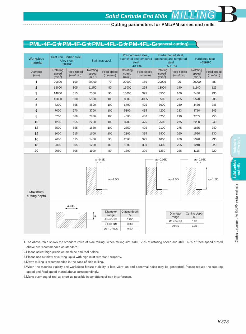
Workpiece material
Cast iron, Carbon steel, Alloy steel ~30HRC
Stainless steel
Pre-hardened steel, quenched and tempered
steel ~40HRC
Pre-hardened steel, quenched and tempered
steel ~50HRC
Hardened steel ~55HRC
Diameter(mm)
Rotating speed(min-1)
Feed speed(mm/min)
Rotating speed(min-1)
Feed speed(mm/min)
Rotating speed(min-1)
Feed speed(mm/min)
Rotating speed(min-1)
Feed speed(mm/min)
Rotating speed(min-1)
Feed speed(mm/min)
1 20000 190 20000 70 20000 150 20000 95 20000 85
2 15000 305 11150 80 15000 265 13000 140 11140 125
3 14000 515 7500 95 10600 395 8500 260 7430 230
4 10800 530 5500 100 8000 4055 6500 265 5570 235
5 8200 555 4500 100 6400 425 5000 280 4460 245
6 7000 570 3700 100 5300 435 4200 283 3710 245
8 5200 560 2800 100 4000 430 3200 290 2785 255
10 4200 555 2200 100 3200 425 2500 275 2230 240
12 3500 555 1850 100 2650 425 2100 275 1855 240
14 3000 515 1600 100 2300 395 1800 260 1590 230
16 2600 515 1400 95 2000 395 1600 260 1390 230
18 2300 505 1250 80 1800 390 1400 255 1240 220
20 2050 505 1100 80 1600 390 1250 255 1115 220
Maximum cutting depth
1.The above table shows the standard value of side milling. When milling slot, 50%~70% of rotating speed and 40%~60% of feed speed stated
above are recommended as standard.
2.Please select high-precision machine and tool holder.
3.Please use air blow or cutting liquid with high mist retardant property.
4.Down milling is recommended in the case of side milling.
5.When the machine rigidity and workpiece fixture stability is low, vibration and abnormal noise may be generated. Please reduce the rotating
speed and feed speed stated above correspondingly.
6.Make overhang of tool as short as possible in conditions of non-interference.
Diameter range
Cutting depth ap
Ø1≤D<Ø3 0.15D
Ø3≤D<Ø6 0.3D
Ø6≤D<Ø20 0.5D
ae=1D
apDiameter
rangeCutting depth
ap
Ø1≤D<Ø3 0.1D
Ø3≤D 0.2D
ae=0.1D
ap=1.5D
ae=0.05D
ap=1.5D
ae=0.03D
ap=1.5D
PML-4F-G★PM-4F-G★PML-4FL-G★PM-4FL-G(general cutting)
Cutt
ing
para
met
ers f
or P
ML/
PM se
ries e
nd m
ills
B
B 373
Solid Carbide End Mills MILLINGMILLING
Inde
xabl
e m
illin
g to
ols
Solid
car
bide
en
d m
ills
Cutting parameters for PML/PM series end mills
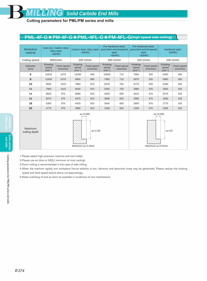
Workpiece material
Cast iron, Carbon steel, Alloy steel ~30HRC
Carbon steel, Alloy steel ~40HRC
Pre-hardened steel, quenched and tempered
steel ~45HRC
Pre-hardened steel, quenched and tempered
steel ~50HRC
Hardened steel~55HRC
Cutting speed 300m/min 250 m/min 200 m/min 150 m/min 100 m/min
Diameter(mm)
Rotating speed(min-1)
Feed speed(mm/min)
Rotating speed(min-1)
Feed speed(mm/min)
Rotating speed(min-1)
Feed speed(mm/min)
Rotating speed(min-1)
Feed speed(mm/min)
Rotating speed(min-1)
Feed speed(mm/min)
6 15915 1075 13260 900 10600 715 7960 535 5300 360
8 11935 1070 9950 885 7960 715 5970 535 3980 360
10 9550 1015 7960 870 6370 700 4775 525 3180 345
12 7960 1015 6630 870 5300 700 3980 525 2650 345
14 6820 975 5685 815 4550 650 3410 570 2275 325
16 5970 975 4975 815 3980 650 2985 570 1990 325
18 5305 975 4420 815 3540 650 2650 570 1770 325
20 4775 975 3980 815 3180 650 2390 570 1590 325
Maximum cutting depth
1.Please select high-precision machine and tool holder.
2.Please use air blow or MQL( minimum oil mist cooling).
3.Down milling is recommended in the case of side milling.
4.When the machine rigidity and workpiece fixture stability is low, vibration and abnormal noise may be generated. Please reduce the rotating
speed and feed speed stated above correspondingly.
5.Make overhang of tool as short as possible in conditions of non-interference.
ae=0.05D
ap=1.5D
Maximum ae=1.0mm
ae=0.03D
ap=1D
Maximum ae=0.5mm
PML-4F-G★PM-4F-G★PML-4FL-G★PM-4FL-G(high speed side milling)
Cutting parameters for PM
L/PM series end m
ills
B
B 374
Solid Carbide End MillsMILLINGMILLING
Indexable m
illing toolsSolid carbide
end mills
Cutting parameters for PML/PM series end mills
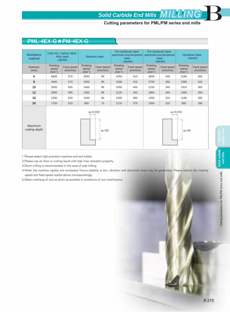
Workpiece material
Cast iron, Carbon steel, Alloy steel ~30HRC
Stainless steel
Pre-hardened steel, quenched and tempered
steel ~40HRC
Pre-hardened steel, quenched and tempered
steel ~50HRC
Hardened steel ~55HRC
Diameter(mm)
Rotating speed(min-1)
Feed speed(mm/min)
Rotating speed(min-1)
Feed speed(mm/min)
Rotating speed(min-1)
Feed speed(mm/min)
Rotating speed(min-1)
Feed speed(mm/min)
Rotating speed(min-1)
Feed speed(mm/min)
6 5800 570 2650 85 4250 410 3600 345 3180 305
8 4400 570 2000 85 3180 410 2700 350 2390 310
10 3500 555 1600 85 2550 400 2150 340 1910 300
12 2900 555 1350 85 2120 400 1800 340 1590 300
16 2200 520 1000 80 1590 380 1350 315 1195 280
20 1750 510 800 75 1270 375 1050 310 955 280
Maximum cutting depth
1.Please select high-precision machine and tool holder.
2.Please use air blow or cutting liquid with high mist retardant property.
3.Down milling is recommended in the case of side milling.
4.When the machine rigidity and workpiece fixture stability is low, vibration and abnormal noise may be generated. Please reduce the rotating
speed and feed speed stated above correspondingly.
5.Make overhang of tool as short as possible in conditions of non-interference.
ae=0.02D
ap=3D
ae=0.01D
ap=3D
PML-4EX-G★PM-4EX-G
Cutt
ing
para
met
ers f
or P
ML/
PM se
ries e
nd m
ills
B
B 375
Solid Carbide End Mills MILLINGMILLING
Inde
xabl
e m
illin
g to
ols
Solid
car
bide
en
d m
ills
Cutting parameters for PML/PM series end mills

Workpiece material
Cast iron, Carbon steel, Alloy steel ~30HRC
Stainless steel
Pre-hardened steel, quenched and tempered
steel ~40HRC
Pre-hardened steel, quenched and tempered
steel ~50HRC
Hardened steel ~55HRC
Diameter(mm)
Rotating speed(min-1)
Feed speed(mm/min)
Rotating speed(min-1)
Feed speed(mm/min)
Rotating speed(min-1)
Feed speed(mm/min)
Rotating speed(min-1)
Feed speed(mm/min)
Rotating speed(min-1)
Feed speed(mm/min)
1 20000 300 20000 108 20000 240 20000 180 20000 135
2 15000 480 11150 120 15000 420 13000 270 11140 195
3 14000 815 7500 145 10600 630 8500 495 7430 360
4 10800 840 5500 150 8000 645 6500 505 5570 370
5 8200 875 4500 150 6400 675 5000 530 4460 390
6 7000 900 3700 165 5300 690 4200 540 3710 390
8 5200 890 2800 165 4000 680 3200 555 2785 405
10 4200 875 2200 165 3200 675 2500 525 2230 375
12 3500 875 1850 165 2650 675 2100 525 1855 375
14 3000 815 1600 150 2300 630 1800 495 1590 360
16 2600 815 1400 145 2000 630 1600 495 1390 360
18 2300 805 1250 125 1800 620 1400 485 1240 350
20 2050 805 1100 125 1600 620 1250 485 1115 350
Maximum cutting depth
1.The above table shows the standard value of side milling. When milling slot, 50%~70% of rotating speed and 40%~60% of feed speed stated
above are recommended as standard.
2.Please select high-precision machine and tool holder.
3.Please use air blow or cutting liquid with high mist retardant property.
4.Down milling is recommended in the case of side milling.
5.When the machine rigidity and workpiece fixture stability is low, vibration and abnormal noise may be generated. Please reduce the rotating
speed and feed speed stated above correspondingly.
6.Make overhang of tool as short as possible in conditions of non-interference.
Diameter range
Cutting depth ap
Ø1≤D<Ø3 0.15D
Ø3≤D<Ø6 0.3D
Ø6≤D<Ø20 0.5D
ae=1D
apDiameter
rangeCutting depth
ap
Ø1≤D<Ø3 0.1D
Ø3≤D 0.2D
ae=0.1D
ap=1.5D
ae=0.05D
ap=1.5D
ae=0.03D
ap=1.5D
PML-4E★PM-4E★PML-4EL★PM-4EL(general cutting)
Cutting parameters for PM
L/PM series end m
ills
B
B 376
Solid Carbide End MillsMILLINGMILLING
Indexable m
illing toolsSolid carbide
end mills
Cutting parameters for PML/PM series end mills
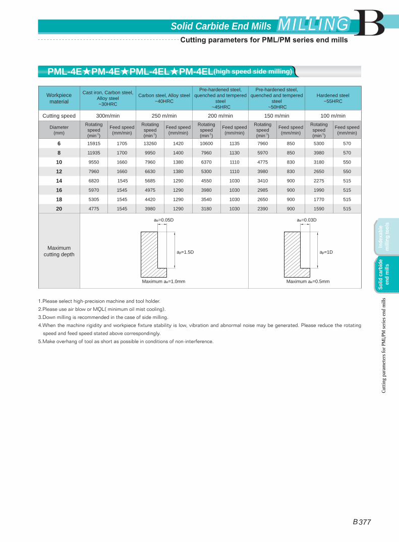
Workpiece material
Cast iron, Carbon steel, Alloy steel ~30HRC
Carbon steel, Alloy steel ~40HRC
Pre-hardened steel, quenched and tempered
steel ~45HRC
Pre-hardened steel, quenched and tempered
steel ~50HRC
Hardened steel~55HRC
Cutting speed 300m/min 250 m/min 200 m/min 150 m/min 100 m/min
Diameter(mm)
Rotating speed(min-1)
Feed speed(mm/min)
Rotating speed(min-1)
Feed speed(mm/min)
Rotating speed(min-1)
Feed speed(mm/min)
Rotating speed(min-1)
Feed speed(mm/min)
Rotating speed(min-1)
Feed speed(mm/min)
6 15915 1705 13260 1420 10600 1135 7960 850 5300 570
8 11935 1700 9950 1400 7960 1130 5970 850 3980 570
10 9550 1660 7960 1380 6370 1110 4775 830 3180 550
12 7960 1660 6630 1380 5300 1110 3980 830 2650 550
14 6820 1545 5685 1290 4550 1030 3410 900 2275 515
16 5970 1545 4975 1290 3980 1030 2985 900 1990 515
18 5305 1545 4420 1290 3540 1030 2650 900 1770 515
20 4775 1545 3980 1290 3180 1030 2390 900 1590 515
Maximum cutting depth
1.Please select high-precision machine and tool holder.
2.Please use air blow or MQL( minimum oil mist cooling).
3.Down milling is recommended in the case of side milling.
4.When the machine rigidity and workpiece fixture stability is low, vibration and abnormal noise may be generated. Please reduce the rotating
speed and feed speed stated above correspondingly.
5.Make overhang of tool as short as possible in conditions of non-interference.
ae=0.05D
ap=1.5D
Maximum ae=1.0mm
ae=0.03D
ap=1D
Maximum ae=0.5mm
PML-4E★PM-4E★PML-4EL★PM-4EL(high speed side milling)
Cutt
ing
para
met
ers f
or P
ML/
PM se
ries e
nd m
ills
B
B 377
Solid Carbide End Mills MILLINGMILLING
Inde
xabl
e m
illin
g to
ols
Solid
car
bide
en
d m
ills
Cutting parameters for PML/PM series end mills
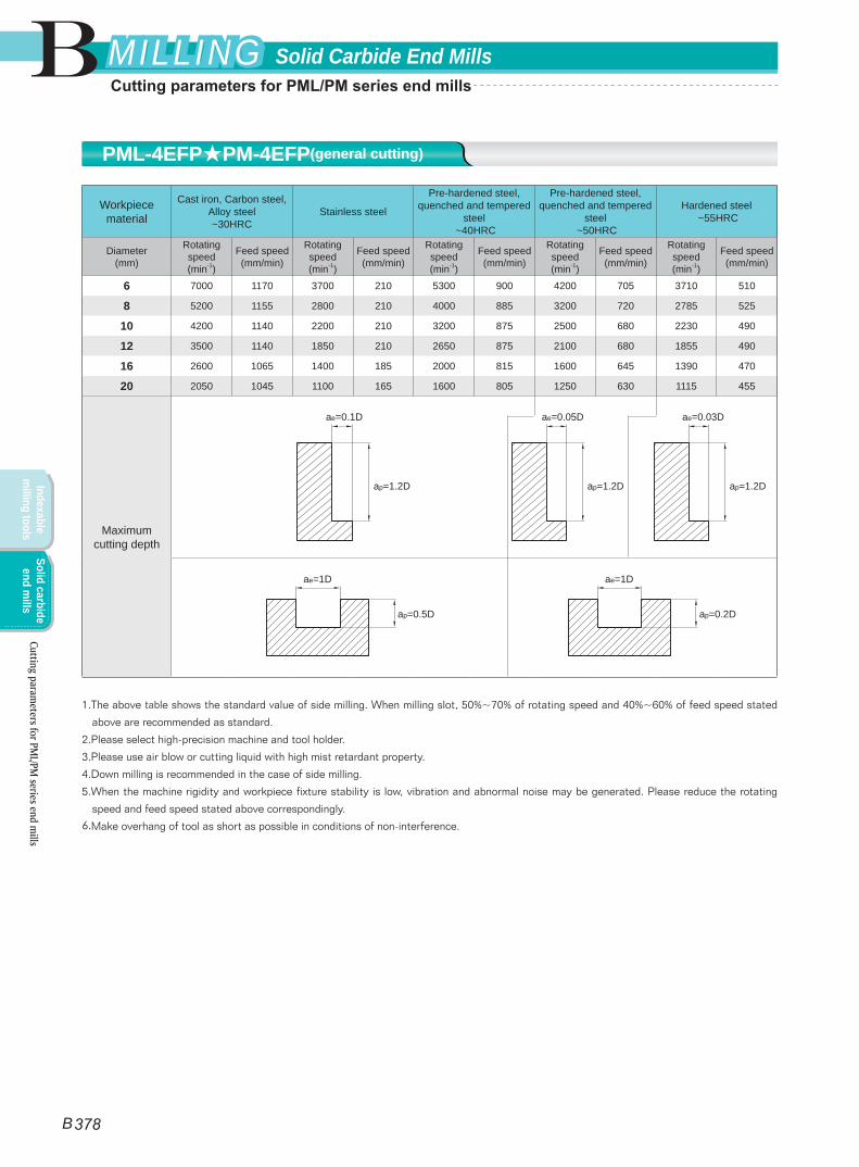
Workpiece material
Cast iron, Carbon steel, Alloy steel ~30HRC
Stainless steel
Pre-hardened steel, quenched and tempered
steel ~40HRC
Pre-hardened steel, quenched and tempered
steel ~50HRC
Hardened steel ~55HRC
Diameter(mm)
Rotating speed(min-1)
Feed speed(mm/min)
Rotating speed(min-1)
Feed speed(mm/min)
Rotating speed(min-1)
Feed speed(mm/min)
Rotating speed(min-1)
Feed speed(mm/min)
Rotating speed(min-1)
Feed speed(mm/min)
6 7000 1170 3700 210 5300 900 4200 705 3710 510
8 5200 1155 2800 210 4000 885 3200 720 2785 525
10 4200 1140 2200 210 3200 875 2500 680 2230 490
12 3500 1140 1850 210 2650 875 2100 680 1855 490
16 2600 1065 1400 185 2000 815 1600 645 1390 470
20 2050 1045 1100 165 1600 805 1250 630 1115 455
Maximum cutting depth
1.The above table shows the standard value of side milling. When milling slot, 50%~70% of rotating speed and 40%~60% of feed speed stated
above are recommended as standard.
2.Please select high-precision machine and tool holder.
3.Please use air blow or cutting liquid with high mist retardant property.
4.Down milling is recommended in the case of side milling.
5.When the machine rigidity and workpiece fixture stability is low, vibration and abnormal noise may be generated. Please reduce the rotating
speed and feed speed stated above correspondingly.
6.Make overhang of tool as short as possible in conditions of non-interference.
ae=1D
ap=0.5D
ae=1D
ap=0.2D
ae=0.1D
ap=1.2D
ae=0.05D
ap=1.2D
ae=0.03D
ap=1.2D
PML-4EFP★PM-4EFP(general cutting)
Cutting parameters for PM
L/PM series end m
ills
B
B 378
Solid Carbide End MillsMILLINGMILLING
Indexable m
illing toolsSolid carbide
end mills
Cutting parameters for PML/PM series end mills
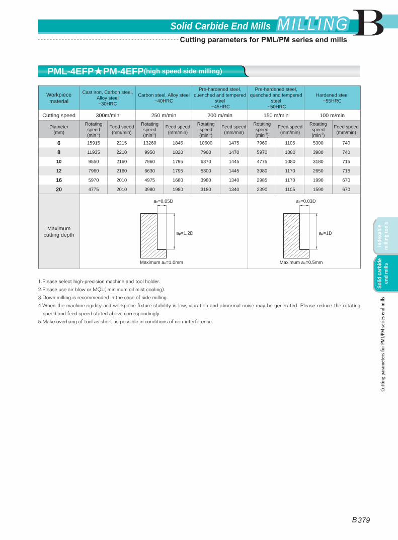
Workpiece material
Cast iron, Carbon steel, Alloy steel ~30HRC
Carbon steel, Alloy steel ~40HRC
Pre-hardened steel, quenched and tempered
steel ~45HRC
Pre-hardened steel, quenched and tempered
steel ~50HRC
Hardened steel~55HRC
Cutting speed 300m/min 250 m/min 200 m/min 150 m/min 100 m/min
Diameter(mm)
Rotating speed(min-1)
Feed speed(mm/min)
Rotating speed(min-1)
Feed speed(mm/min)
Rotating speed(min-1)
Feed speed(mm/min)
Rotating speed(min-1)
Feed speed(mm/min)
Rotating speed(min-1)
Feed speed(mm/min)
6 15915 2215 13260 1845 10600 1475 7960 1105 5300 740
8 11935 2210 9950 1820 7960 1470 5970 1080 3980 740
10 9550 2160 7960 1795 6370 1445 4775 1080 3180 715
12 7960 2160 6630 1795 5300 1445 3980 1170 2650 715
16 5970 2010 4975 1680 3980 1340 2985 1170 1990 670
20 4775 2010 3980 1980 3180 1340 2390 1105 1590 670
Maximum cutting depth
1.Please select high-precision machine and tool holder.
2.Please use air blow or MQL( minimum oil mist cooling).
3.Down milling is recommended in the case of side milling.
4.When the machine rigidity and workpiece fixture stability is low, vibration and abnormal noise may be generated. Please reduce the rotating
speed and feed speed stated above correspondingly.
5.Make overhang of tool as short as possible in conditions of non-interference.
ae=0.05D
ap=1.2D
Maximum ae=1.0mm
ae=0.03D
ap=1D
Maximum ae=0.5mm
PML-4EFP★PM-4EFP(high speed side milling)
Cutt
ing
para
met
ers f
or P
ML/
PM se
ries e
nd m
ills
B
B 379
Solid Carbide End Mills MILLINGMILLING
Inde
xabl
e m
illin
g to
ols
Solid
car
bide
en
d m
ills
Cutting parameters for PML/PM series end mills
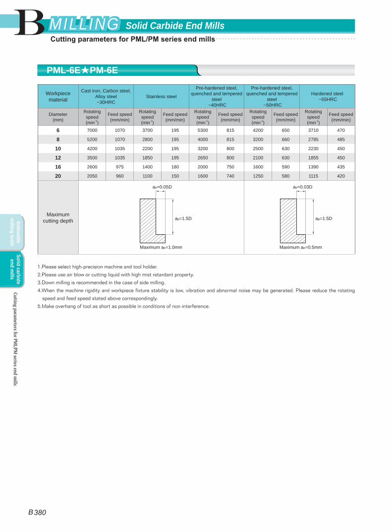
Workpiece material
Cast iron, Carbon steel, Alloy steel ~30HRC
Stainless steel
Pre-hardened steel, quenched and tempered
steel ~40HRC
Pre-hardened steel, quenched and tempered
steel ~50HRC
Hardened steel ~55HRC
Diameter(mm)
Rotating speed(min-1)
Feed speed(mm/min)
Rotating speed(min-1)
Feed speed(mm/min)
Rotating speed(min-1)
Feed speed(mm/min)
Rotating speed(min-1)
Feed speed(mm/min)
Rotating speed(min-1)
Feed speed(mm/min)
6 7000 1070 3700 195 5300 815 4200 650 3710 470
8 5200 1070 2800 195 4000 815 3200 660 2785 485
10 4200 1035 2200 195 3200 800 2500 630 2230 450
12 3500 1035 1850 195 2650 800 2100 630 1855 450
16 2600 975 1400 180 2000 750 1600 590 1390 435
20 2050 960 1100 150 1600 740 1250 580 1115 420
Maximum cutting depth
1.Please select high-precision machine and tool holder.
2.Please use air blow or cutting liquid with high mist retardant property.
3.Down milling is recommended in the case of side milling.
4.When the machine rigidity and workpiece fixture stability is low, vibration and abnormal noise may be generated. Please reduce the rotating
speed and feed speed stated above correspondingly.
5.Make overhang of tool as short as possible in conditions of non-interference.
ae=0.05D
ap=1.5D
Maximum ae=1.0mm
ae=0.03D
ap=1.5D
Maximum ae=0.5mm
PML-6E★PM-6E
Cutting parameters for PM
L/PM series end m
ills
B
B 380
Solid Carbide End MillsMILLINGMILLING
Indexable m
illing toolsSolid carbide
end mills
Cutting parameters for PML/PM series end mills
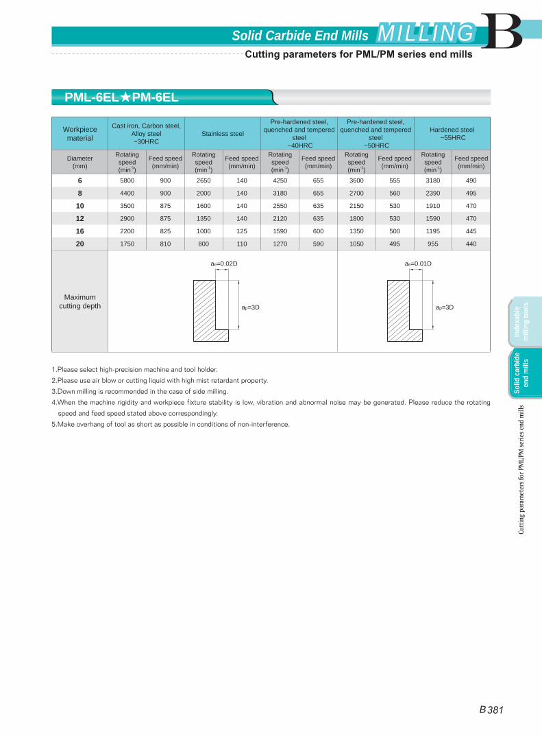
Workpiece material
Cast iron, Carbon steel, Alloy steel ~30HRC
Stainless steel
Pre-hardened steel, quenched and tempered
steel ~40HRC
Pre-hardened steel, quenched and tempered
steel ~50HRC
Hardened steel ~55HRC
Diameter(mm)
Rotating speed(min-1)
Feed speed(mm/min)
Rotating speed(min-1)
Feed speed(mm/min)
Rotating speed(min-1)
Feed speed(mm/min)
Rotating speed(min-1)
Feed speed(mm/min)
Rotating speed(min-1)
Feed speed(mm/min)
6 5800 900 2650 140 4250 655 3600 555 3180 490
8 4400 900 2000 140 3180 655 2700 560 2390 495
10 3500 875 1600 140 2550 635 2150 530 1910 470
12 2900 875 1350 140 2120 635 1800 530 1590 470
16 2200 825 1000 125 1590 600 1350 500 1195 445
20 1750 810 800 110 1270 590 1050 495 955 440
Maximum cutting depth
1.Please select high-precision machine and tool holder.
2.Please use air blow or cutting liquid with high mist retardant property.
3.Down milling is recommended in the case of side milling.
4.When the machine rigidity and workpiece fixture stability is low, vibration and abnormal noise may be generated. Please reduce the rotating
speed and feed speed stated above correspondingly.
5.Make overhang of tool as short as possible in conditions of non-interference.
ae=0.02D
ap=3D
ae=0.01D
ap=3D
PML-6EL★PM-6EL
Cutt
ing
para
met
ers f
or P
ML/
PM se
ries e
nd m
ills
B
B 381
Solid Carbide End Mills MILLINGMILLING
Inde
xabl
e m
illin
g to
ols
Solid
car
bide
en
d m
ills
Cutting parameters for PML/PM series end mills
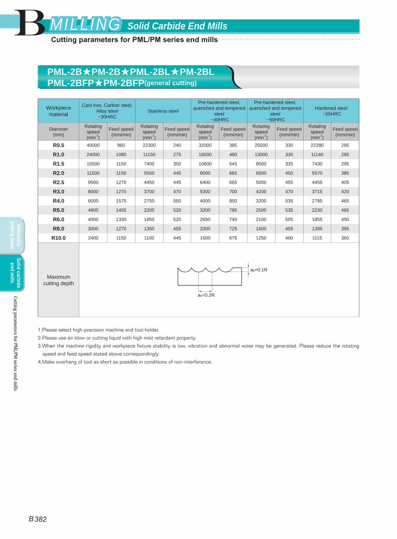
Workpiece material
Cast iron, Carbon steel, Alloy steel ~30HRC
Stainless steel
Pre-hardened steel, quenched and tempered
steel ~40HRC
Pre-hardened steel, quenched and tempered
steel ~50HRC
Hardened steel ~55HRC
Diameter(mm)
Rotating speed(min-1)
Feed speed(mm/min)
Rotating speed(min-1)
Feed speed(mm/min)
Rotating speed(min-1)
Feed speed(mm/min)
Rotating speed(min-1)
Feed speed(mm/min)
Rotating speed(min-1)
Feed speed(mm/min)
R0.5 40000 960 22300 240 32000 385 25000 330 22280 295
R1.0 24000 1080 11150 275 16000 480 13000 330 11140 295
R1.5 15500 1150 7400 350 10600 545 8500 335 7430 295
R2.0 11500 1150 5550 445 8000 665 6500 450 5570 385
R2.5 9500 1270 4450 445 6400 665 5000 455 4455 405
R3.0 8000 1270 3700 470 5300 700 4200 470 3715 420
R4.0 6000 1575 2750 550 4000 850 3200 535 2785 465
R5.0 4800 1455 2200 520 3200 785 2500 535 2230 465
R6.0 4000 1330 1850 520 2650 740 2100 505 1855 450
R8.0 3000 1270 1350 455 2000 725 1600 455 1395 395
R10.0 2400 1150 1100 445 1600 675 1250 400 1115 360
Maximum cutting depth
1.Please select high-precision machine and tool holder.
2.Please use air blow or cutting liquid with high mist retardant property.
3.When the machine rigidity and workpiece fixture stability is low, vibration and abnormal noise may be generated. Please reduce the rotating
speed and feed speed stated above correspondingly.
4.Make overhang of tool as short as possible in conditions of non-interference.
ae=0.2R
ap=0.1R
PML-2B★PM-2B★PML-2BL★PM-2BLPML-2BFP★PM-2BFP(general cutting)
Cutting parameters for PM
L/PM series end m
ills
B
B 382
Solid Carbide End MillsMILLINGMILLING
Indexable m
illing toolsSolid carbide
end mills
Cutting parameters for PML/PM series end mills

Workpiece material
Cast iron, Carbon steel, Alloy steel ~30HRC
Carbon steel, Alloy steel ~400HRC
Pre-hardened steel, quenched and tempered
steel ~45HRC
Pre-hardened steel, quenched and tempered
steel ~50HRC
Hardened steel ~55HRC
Diameter(mm)
Rotating speed(min-1)
Feed speed(mm/min)
Rotating speed(min-1)
Feed speed(mm/min)
Rotating speed(min-1)
Feed speed(mm/min)
Rotating speed(min-1)
Feed speed(mm/min)
Rotating speed(min-1)
Feed speed(mm/min)
R3.0 15000 4800 11500 2750 9500 2250 7960 1885 6370 1510
R4.0 11500 3650 8950 2100 7150 1700 5970 1420 4775 1135
R5.0 9500 3000 7150 1700 5700 1350 4775 1130 3820 905
R6.0 7950 2500 5950 1400 4750 1100 3980 920 3180 735
R8.0 5950 1900 4450 1050 3550 850 2985 760 2390 610
R10.0 4750 1500 3550 850 2850 680 2390 570 1910 455
Maximum cutting depth
1.Please select high-precision machine and tool holder.
2.Please use air blow or cutting liquid with high mist retardant property.
3.When the machine rigidity and workpiece fixture stability is low, vibration and abnormal noise may be generated. Please reduce the rotating
speed and feed speed stated above correspondingly.
4.Make overhang of tool as short as possible in conditions of non-interference.
ae=0.1R
ap=0.05R
PML-2B★PM-2B★PML-2BL★PM-2BLPML-2BFP★PM-2BFP(high speed cutting)
Cutt
ing
para
met
ers f
or P
ML/
PM se
ries e
nd m
ills
B
B 383
Solid Carbide End Mills MILLINGMILLING
Inde
xabl
e m
illin
g to
ols
Solid
car
bide
en
d m
ills
Cutting parameters for PML/PM series end mills
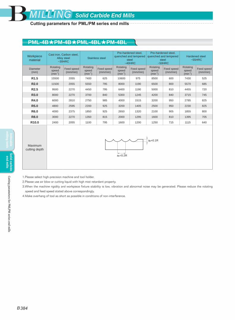
Workpiece material
Cast iron, Carbon steel, Alloy steel ~30HRC
Stainless steel
Pre-hardened steel, quenched and tempered
steel ~40HRC
Pre-hardened steel, quenched and tempered
steel ~50HRC
Hardened steel ~55HRC
Diameter(mm)
Rotating speed(min-1)
Feed speed(mm/min)
Rotating speed(min-1)
Feed speed(mm/min)
Rotating speed(min-1)
Feed speed(mm/min)
Rotating speed(min-1)
Feed speed(mm/min)
Rotating speed(min-1)
Feed speed(mm/min)
R1.5 15500 2055 7400 625 10600 975 8500 600 7430 525
R2.0 11500 2055 5550 795 8000 1190 6500 800 5570 685
R2.5 9500 2270 4450 795 6400 1190 5000 810 4455 720
R3.0 8000 2270 3700 840 5300 1245 4200 840 3715 745
R4.0 6000 2810 2750 985 4000 1515 3200 950 2785 825
R5.0 4800 2595 2200 925 3200 1405 2500 950 2230 825
R6.0 4000 2375 1850 925 2650 1320 2100 905 1855 800
R8.0 3000 2270 1350 815 2000 1295 1600 810 1395 705
R10.0 2400 2055 1100 795 1600 1200 1250 715 1115 640
Maximum cutting depth
1.Please select high-precision machine and tool holder.
2.Please use air blow or cutting liquid with high mist retardant property.
3.When the machine rigidity and workpiece fixture stability is low, vibration and abnormal noise may be generated. Please reduce the rotating
speed and feed speed stated above correspondingly.
4.Make overhang of tool as short as possible in conditions of non-interference.
ae=0.2R
ap=0.1R
PML-4B★PM-4B★PML-4BL★PM-4BL
Cutting parameters for PM
L/PM series end m
ills
B
B 384
Solid Carbide End MillsMILLINGMILLING
Indexable m
illing toolsSolid carbide
end mills
Cutting parameters for PML/PM series end mills

Workpiece materialPre-hardened steel, quenched and
tempered steel ~40HRC
Pre-hardened steel, quenched and tempered steel
~50HRC
Hardened steel ~55HRC
Diameter(mm)
Taper half angle(°)
Effective length(mm)
Rotating speed(min-1)
Feed speed(mm/min)
ap (mm)
Rotating speed(min-1)
Feed speed(mm/min)
ap (mm)
Rotating speed(min-1)
Feed speed(mm/min)
ap (mm)
R0.25
0.5° 3 30000 300 0.03 30000 270 0.03 30000 240 0.03
5 30000 250 0.02 30000 225 0.02 30000 200 0.02
1.0° 3 30000 330 0.03 30000 300 0.03 30000 265 0.03
5 30000 270 0.02 30000 245 0.02 30000 215 0.02
1.5° 3 30000 350 0.03 30000 315 0.03 30000 280 0.03
5 30000 300 0.02 30000 270 0.02 30000 240 0.02
R0.30
0.5° 5 30000 300 0.03 30000 270 0.03 30000 240 0.03
8 30000 250 0.02 30000 225 0.02 30000 200 0.02
1.0°
5 30000 350 0.03 30000 315 0.03 30000 280 0.03
8 30000 300 0.02 30000 270 0.02 30000 240 0.02
10 30000 270 0.02 30000 245 0.02 30000 215 0.02
12 30000 250 0.015 30000 225 0.015 30000 200 0.015
15 30000 250 0.01 30000 225 0.01 30000 200 0.01
1.5° 8 30000 350 0.03 30000 315 0.03 30000 280 0.03
15 30000 300 0.01 30000 270 0.01 30000 240 0.01
R0.40
0.5° 8 30000 350 0.05 30000 315 0.05 30000 280 0.05
12 30000 300 0.04 30000 270 0.04 30000 240 0.04
1.0° 8 30000 400 0.05 30000 360 0.05 30000 320 0.05
12 30000 350 0.04 30000 315 0.04 30000 280 0.04
1.5° 8 30000 450 0.05 30000 405 0.05 30000 360 0.05
12 30000 400 0.04 30000 360 0.04 30000 320 0.04
R0.50
0.5°
10 22000 450 0.05 22000 405 0.05 22000 360 0.05
15 22000 400 0.04 22000 360 0.04 22000 320 0.04
20 22000 370 0.03 22000 335 0.03 22000 295 0.03
25 22000 350 0.01 22000 315 0.01 22000 280 0.01
30 22000 320 0.005 22000 290 0.005 22000 255 0.005
1.0°
10 22000 500 0.05 22000 450 0.05 22000 400 0.05
15 22000 450 0.04 22000 405 0.04 22000 360 0.04
20 22000 430 0.02 22000 390 0.02 22000 345 0.02
25 22000 400 0.015 22000 360 0.015 22000 320 0.015
30 22000 360 0.01 22000 325 0.01 22000 290 0.01
35 22000 320 0.005 22000 290 0.005 22000 255 0.005
Maximum cutting depth
≤0.1R(R<0.5)≤0.2R(R≥0.5)
ap
PM-2BC
Cutt
ing
para
met
ers f
or P
ML/
PM se
ries e
nd m
ills
B
B 385
Solid Carbide End Mills MILLINGMILLING
Inde
xabl
e m
illin
g to
ols
Solid
car
bide
en
d m
ills
Cutting parameters for PML/PM series end mills
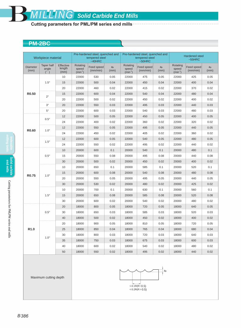
Workpiece materialPre-hardened steel, quenched and
tempered steel ~40HRC
Pre-hardened steel, quenched and tempered steel
~50HRC
Hardened steel ~55HRC
Diameter(mm)
Taper half angle(°)
Effective length(mm)
Rotating speed(min-1)
Feed speed(mm/min)
ap (mm)
Rotating speed(min-1)
Feed speed(mm/min)
ap (mm)
Rotating speed(min-1)
Feed speed(mm/min)
ap (mm)
R0.50
1.5°
10 22000 530 0.05 22000 475 0.05 22000 425 0.05
15 22000 500 0.04 22000 450 0.04 22000 400 0.04
20 22000 460 0.02 22000 415 0.02 22000 370 0.02
2° 15 22000 600 0.04 22000 540 0.04 22000 480 0.04
20 22000 500 0.02 22000 450 0.02 22000 400 0.02
3° 20 22000 550 0.03 22000 495 0.03 22000 440 0.03
5° 20 22000 600 0.03 22000 540 0.03 22000 480 0.03
R0.60
0.5° 12 22000 500 0.05 22000 450 0.05 22000 400 0.05
24 22000 400 0.02 22000 360 0.02 22000 320 0.02
1.0° 12 22000 550 0.05 22000 495 0.05 22000 440 0.05
24 22000 450 0.02 22000 405 0.02 22000 360 0.02
1.5° 12 22000 600 0.05 22000 540 0.05 22000 480 0.05
24 22000 550 0.02 22000 495 0.02 22000 440 0.02
R0.75
0.5°
10 20000 600 0.1 20000 540 0.1 20000 480 0.1
15 20000 550 0.08 20000 495 0.08 20000 440 0.08
30 20000 500 0.02 20000 450 0.02 20000 400 0.02
1.0°
10 20000 650 0.1 20000 585 0.1 20000 520 0.1
15 20000 600 0.08 20000 540 0.08 20000 480 0.08
20 20000 550 0.05 20000 495 0.05 20000 440 0.05
30 20000 530 0.02 20000 480 0.02 20000 425 0.02
1.5°
10 20000 700 0.1 20000 630 0.1 20000 560 0.1
15 20000 650 0.08 20000 585 0.08 20000 520 0.08
30 20000 600 0.02 20000 540 0.02 20000 480 0.02
R1.0
0.5°
20 18000 800 0.05 18000 720 0.05 18000 640 0.05
30 18000 650 0.03 18000 585 0.03 18000 520 0.03
40 18000 500 0.02 18000 450 0.02 18000 400 0.02
1.0°
20 18000 900 0.05 18000 810 0.05 18000 720 0.05
25 18000 850 0.04 18000 765 0.04 18000 680 0.04
30 18000 800 0.03 18000 720 0.03 18000 640 0.03
35 18000 750 0.03 18000 675 0.03 18000 600 0.03
40 18000 600 0.02 18000 540 0.02 18000 480 0.02
50 18000 550 0.02 18000 495 0.02 18000 440 0.02
Maximum cutting depth
≤0.1R(R<0.5)≤0.2R(R≥0.5)
ap
PM-2BC
Cutting parameters for PM
L/PM series end m
ills
B
B 386
Solid Carbide End MillsMILLINGMILLING
Indexable m
illing toolsSolid carbide
end mills
Cutting parameters for PML/PM series end mills
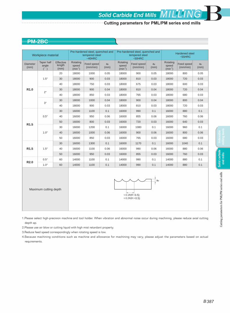
Workpiece materialPre-hardened steel, quenched and
tempered steel ~40HRC
Pre-hardened steel, quenched and tempered steel
~50HRC
Hardened steel ~55HRC
Diameter(mm)
Taper half angle(°)
Effective length(mm)
Rotating speed(min-1)
Feed speed(mm/min)
ap (mm)
Rotating speed(min-1)
Feed speed(mm/min)
ap (mm)
Rotating speed(min-1)
Feed speed(mm/min)
ap (mm)
R1.0
1.5°
20 18000 1000 0.05 18000 900 0.05 18000 800 0.05
30 18000 900 0.03 18000 810 0.03 18000 720 0.03
40 18000 750 0.03 18000 675 0.03 18000 600 0.03
2° 30 18000 900 0.04 18000 810 0.04 18000 720 0.04
40 18000 850 0.03 18000 765 0.03 18000 680 0.03
3° 30 18000 1000 0.04 18000 900 0.04 18000 800 0.04
40 18000 900 0.03 18000 810 0.03 18000 720 0.03
R1.5
0.5°
30 16000 1100 0.1 16000 990 0.1 16000 880 0.1
40 16000 950 0.06 16000 855 0.06 16000 760 0.06
50 16000 800 0.03 16000 720 0.03 16000 640 0.03
1.0°
30 16000 1200 0.1 16000 1080 0.1 16000 960 0.1
40 16000 1000 0.06 16000 900 0.06 16000 800 0.06
50 16000 850 0.03 16000 765 0.03 16000 680 0.03
R1.5 1.5°
30 16000 1300 0.1 16000 1170 0.1 16000 1040 0.1
40 16000 1100 0.06 16000 990 0.06 16000 880 0.06
50 16000 950 0.03 16000 855 0.03 16000 760 0.03
R2.00.5° 60 14000 1100 0.1 14000 990 0.1 14000 880 0.1
1.0° 60 14000 1100 0.1 14000 990 0.1 14000 880 0.1
Maximum cutting depth
1.Please select high-precision machine and tool holder. When vibration and abnormal noise occur during machining, please reduce axial cutting
depth ap.
2.Please use air blow or cutting liquid with high mist retardant property.
3.Reduce feed speed correspondingly when rotating speed is low.
4.Because machining conditions such as machine and allowance for machining may vary, please adjust the parameters based on actual
requirements.
≤0.1R(R<0.5)≤0.2R(R≥0.5)
ap
PM-2BC
Cutt
ing
para
met
ers f
or P
ML/
PM se
ries e
nd m
ills
B
B 387
Solid Carbide End Mills MILLINGMILLING
Inde
xabl
e m
illin
g to
ols
Solid
car
bide
en
d m
ills
Cutting parameters for PML/PM series end mills
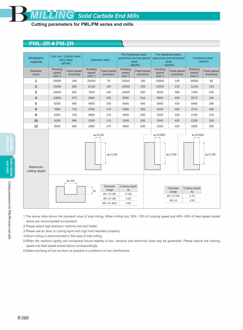
Workpiece material
Cast iron, Carbon steel, Alloy steel ~30HRC
Stainless steel
Pre-hardened steel, quenched and tempered
steel ~40HRC
Pre-hardened steel, quenched and tempered
steel ~50HRC
Hardened steel ~55HRC
Diameter(mm)
Rotating speed(min-1)
Feed speed(mm/min)
Rotating speed(min-1)
Feed speed(mm/min)
Rotating speed(min-1)
Feed speed(mm/min)
Rotating speed(min-1)
Feed speed(mm/min)
Rotating speed(min-1)
Feed speed(mm/min)
1 20000 240 20000 75 20000 195 20000 145 20000 95
2 15000 385 11150 100 15000 335 13000 215 11140 130
3 14000 655 7500 145 10600 505 8500 395 7430 245
4 10800 675 5500 155 8000 515 6500 405 5570 245
5 8200 695 4500 155 6400 540 5000 425 4460 260
6 7000 720 3700 170 5300 555 4200 435 3710 260
8 5200 720 2800 170 4000 555 3200 440 2785 275
10 4200 695 2200 170 3200 535 2500 420 2230 255
12 3500 695 1850 170 2650 535 2100 420 1855 255
Maximum cutting depth
1.The above table shows the standard value of side milling. When milling slot, 50%~70% of rotating speed and 40%~60% of feed speed stated
above are recommended as standard.
2.Please select high-precision machine and tool holder.
3.Please use air blow or cutting liquid with high mist retardant property.
4.Down milling is recommended in the case of side milling.
5.When the machine rigidity and workpiece fixture stability is low, vibration and abnormal noise may be generated. Please reduce the rotating
speed and feed speed stated above correspondingly.
6.Make overhang of tool as short as possible in conditions of non-interference.
Diameter range
Cutting depth ap
Ø1≤D<Ø3 0.15D
Ø3≤D<Ø6 0.3D
Ø6≤D<Ø20 0.5D
ae=1D
apDiameter
rangeCutting depth
ap
Ø1≤D<Ø3 0.1D
Ø3≤D 0.2D
ae=0.1D
ap=1.5D
ae=0.05D
ap=1.5D
ae=0.03D
ap=1.5D
PML-2R★PM-2R
Cutting parameters for PM
L/PM series end m
ills
B
B 388
Solid Carbide End MillsMILLINGMILLING
Indexable m
illing toolsSolid carbide
end mills
Cutting parameters for PML/PM series end mills
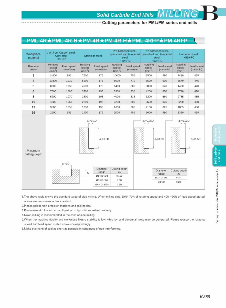
Workpiece material
Cast iron, Carbon steel, Alloy steel ~30HRC
Stainless steel
Pre-hardened steel, quenched and tempered
steel ~40HRC
Pre-hardened steel, quenched and tempered
steel ~50HRC
Hardened steel ~55HRC
Diameter(mm)
Rotating speed(min-1)
Feed speed(mm/min)
Rotating speed(min-1)
Feed speed(mm/min)
Rotating speed(min-1)
Feed speed(mm/min)
Rotating speed(min-1)
Feed speed(mm/min)
Rotating speed(min-1)
Feed speed(mm/min)
3 14000 985 7500 175 10600 755 8500 590 7430 435
4 10800 1010 5500 175 8000 770 6500 600 5570 445
5 8200 1055 4500 175 6400 805 5000 640 4460 470
6 7000 1080 3700 195 5300 830 4200 650 3710 470
8 5200 1070 2800 195 4000 815 3200 660 2785 485
10 4200 1055 2200 195 3200 805 2500 625 2230 450
12 3500 1055 1850 195 2650 805 2100 625 1855 450
16 2600 985 1400 175 2000 755 1600 590 1390 435
Maximum cutting depth
1.The above table shows the standard value of side milling. When milling slot, 50%~70% of rotating speed and 40%~60% of feed speed stated
above are recommended as standard.
2.Please select high-precision machine and tool holder.
3.Please use air blow or cutting liquid with high mist retardant property.
4.Down milling is recommended in the case of side milling.
5.When the machine rigidity and workpiece fixture stability is low, vibration and abnormal noise may be generated. Please reduce the rotating
speed and feed speed stated above correspondingly.
6.Make overhang of tool as short as possible in conditions of non-interference.
Diameter range
Cutting depth ap
Ø1≤D<Ø3 0.15D
Ø3≤D<Ø6 0.3D
Ø6≤D<Ø20 0.5D
ae=1D
apDiameter
rangeCutting depth
ap
Ø1≤D<Ø3 0.1D
Ø3≤D 0.2D
ae=0.1D
ap=1.5D
ae=0.05D
ap=1.5D
ae=0.03D
ap=1.5D
PML-4R★PML-4R-H★PM-4R★PM-4R-H★PML-4RFP★PM-4RFP
Cutt
ing
para
met
ers f
or P
ML/
PM se
ries e
nd m
ills
B
B 389
Solid Carbide End Mills MILLINGMILLING
Inde
xabl
e m
illin
g to
ols
Solid
car
bide
en
d m
ills
Cutting parameters for PML/PM series end mills
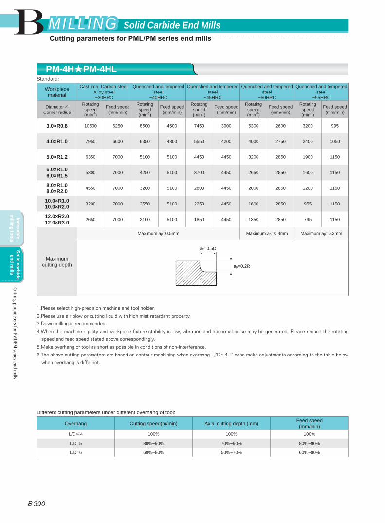
Workpiece material
Cast iron, Carbon steel, Alloy steel ~30HRC
Quenched and tempered steel
~40HRC
Quenched and tempered steel
~45HRC
Quenched and tempered steel
~50HRC
Quenched and tempered steel
~55HRC
Diameter×Corner radius
Rotating speed(min-1)
Feed speed(mm/min)
Rotating speed(min-1)
Feed speed(mm/min)
Rotating speed(min-1)
Feed speed(mm/min)
Rotating speed(min-1)
Feed speed(mm/min)
Rotating speed(min-1)
Feed speed(mm/min)
3.0×R0.8 10500 6250 8500 4500 7450 3900 5300 2600 3200 995
4.0×R1.0 7950 6600 6350 4800 5550 4200 4000 2750 2400 1050
5.0×R1.2 6350 7000 5100 5100 4450 4450 3200 2850 1900 1150
6.0×R1.0 6.0×R1.5 5300 7000 4250 5100 3700 4450 2650 2850 1600 1150
8.0×R1.0 8.0×R2.0 4550 7000 3200 5100 2800 4450 2000 2850 1200 1150
10.0×R1.0 10.0×R2.0 3200 7000 2550 5100 2250 4450 1600 2850 955 1150
12.0×R2.0 12.0×R3.0 2650 7000 2100 5100 1850 4450 1350 2850 795 1150
Maximum cutting depth
Maximum ap=0.5mm Maximum ap=0.4mm Maximum ap=0.2mm
1.Please select high-precision machine and tool holder.
2.Please use air blow or cutting liquid with high mist retardant property.
3.Down milling is recommended.
4.When the machine rigidity and workpiece fixture stability is low, vibration and abnormal noise may be generated. Please reduce the rotating
speed and feed speed stated above correspondingly.
5.Make overhang of tool as short as possible in conditions of non-interference.
6.The above cutting parameters are based on contour machining when overhang L/D≤4. Please make adjustments according to the table below
when overhang is different.
ae=0.5D
ap=0.2R
Different cutting parameters under different overhang of tool:
Overhang Cutting speed(m/min) Axial cutting depth (mm) Feed speed(mm/min)
L/D≤4 100% 100% 100%
L/D=5 80%~90% 70%~90% 80%~90%
L/D=6 60%~80% 50%~70% 60%~80%
Standard:PM-4H★PM-4HL
Cutting parameters for PM
L/PM series end m
ills
B
B 390
Solid Carbide End MillsMILLINGMILLING
Indexable m
illing toolsSolid carbide
end mills
Cutting parameters for PML/PM series end mills
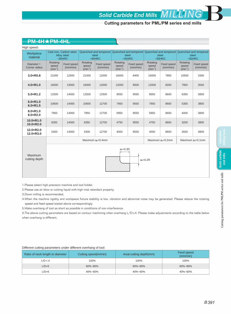
Workpiece material
Cast iron, Carbon steel, Alloy steel ~30HRC
Quenched and tempered steel
~40HRC
Quenched and tempered steel
~45HRC
Quenched and tempered steel
~50HRC
Quenched and tempered steel
~55HRC
Diameter×Corner radius
Rotating speed(min-1)
Feed speed(mm/min)
Rotating speed(min-1)
Feed speed(mm/min)
Rotating speed(min-1)
Feed speed(mm/min)
Rotating speed(min-1)
Feed speed(mm/min)
Rotating speed(min-1)
Feed speed(mm/min)
3.0×R0.8 21000 12500 21000 12000 16000 8400 16000 7850 10500 3300
4.0×R1.0 16000 13000 16000 12000 12000 9000 12000 8200 7950 3550
5.0×R1.2 12500 14000 12500 12500 9550 9550 9550 8600 6350 3800
6.0×R1.0 6.0×R1.5 10600 14000 10600 12700 7950 9550 7950 8600 5300 3800
8.0×R1.0 8.0×R2.0 7950 14000 7950 12700 5950 9550 5950 8600 4000 3800
10.0×R1.0 10.0×R2.0 6350 14000 6350 12700 4750 9550 4750 8600 3200 3800
12.0×R2.0 12.0×R3.0 5300 14000 5300 12700 4000 9550 4000 8600 2650 3800
Maximum cutting depth
Maximum ap=0.4mm Maximum ap=0.2mm Maximum ap=0.1mm
1.Please select high-precision machine and tool holder.
2.Please use air blow or cutting liquid with high mist retardant property.
3.Down milling is recommended.
4.When the machine rigidity and workpiece fixture stability is low, vibration and abnormal noise may be generated. Please reduce the rotating
speed and feed speed stated above correspondingly.
5.Make overhang of tool as short as possible in conditions of non-interference.
6.The above cutting parameters are based on contour machining when overhang L/D≤4. Please make adjustments according to the table below
when overhang is different.
ae=0.3D
ap=0.2R
Different cutting parameters under different overhang of tool:
Ratio of neck length to diameter Cutting speed(m/min) Axial cutting depth(mm) Feed speed(mm/min)
L/D≤4 100% 100% 100%
L/D=5 60%~80% 60%~80% 60%~80%
L/D=6 40%~60% 40%~60% 40%~60%
High speed:PM-4H★PM-4HL
Cutt
ing
para
met
ers f
or P
ML/
PM se
ries e
nd m
ills
B
B 391
Solid Carbide End Mills MILLINGMILLING
Inde
xabl
e m
illin
g to
ols
Solid
car
bide
en
d m
ills
Cutting parameters for PML/PM series end mills
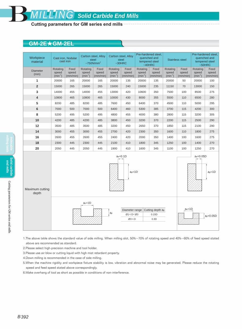
Workpiece material
Cast iron, Nodular cast iron
Carbon steel, Alloy steel
~750N/mm2
Carbon steel, Alloy steel
~30HRC
Pre-hardened steel, quenched and tempered steel
~40HRC
Stainless steel
Pre-hardened steel, quenched and tempered steel
~50HRC
Diameter(mm)
Rotating speed(min-1)
Feed speed
(mm/min)
Rotating speed(min-1)
Feed speed
(mm/min)
Rotating speed(min-1)
Feed speed
(mm/min)
Rotating speed(min-1)
Feed speed
(mm/min)
Rotating speed(min-1)
Feed speed
(mm/min)
Rotating speed(min-1)
Feed speed
(mm/min)
1 20000 165 20000 165 20000 135 20000 135 20000 50 20000 100
2 15000 265 15000 265 15000 240 15000 235 11150 70 13000 150
3 14000 455 14000 455 13000 420 10600 350 7500 100 8500 275
4 10800 465 10800 465 10000 430 8000 355 5500 110 6500 280
5 8200 485 8200 485 7600 450 6400 370 4500 110 5000 295
6 7000 500 7000 500 6400 460 5300 385 3700 115 4200 300
8 5200 495 5200 495 4800 455 4000 380 2800 115 3200 305
10 4200 485 4200 485 3800 450 3200 370 2200 115 2500 290
12 3500 485 3500 485 3200 450 2650 370 1850 115 2100 290
14 3000 455 3000 455 2700 420 2300 350 1600 110 1800 275
16 2600 455 2600 455 2400 420 2000 350 1400 100 1600 275
18 2300 445 2300 445 2100 410 1800 345 1250 100 1400 270
20 2050 445 2050 445 1900 410 1600 345 1100 100 1250 270
Maximum cutting depth
1.The above table shows the standard value of side milling. When milling slot, 50%~70% of rotating speed and 40%~60% of feed speed stated
above are recommended as standard.
2.Please select high-precision machine and tool holder.
3.Please use air blow or cutting liquid with high mist retardant property.
4.Down milling is recommended in the case of side milling.
5.When the machine rigidity and workpiece fixture stability is low, vibration and abnormal noise may be generated. Please reduce the rotating
speed and feed speed stated above correspondingly.
6.Make overhang of tool as short as possible in conditions of non-interference.
Diameter range Cutting depth ap
Ø1≤D<Ø3 0.15D
Ø3≤D 0.3D
ae=1D
ap
ae=1D
ap=0.05D
ae=0.1D
ap=1D
ae=0.05D
ap=1D
GM-2E★GM-2EL
Cutting parameters for GM
series end mills
B 392
B Solid Carbide End MillsMILLINGMILLING
Indexable m
illing toolsSolid carbide
end mills
Cutting parameters for GM series end mills

Workpiece material
Cast iron, Nodular cast iron
Carbon steel, Alloy steel
~750N/mm2
Carbon steel, Alloy steel
~30HRC
Pre-hardened steel, quenched and tempered steel
~40HRC
Stainless steel
Pre-hardened steel, quenched and tempered steel
~50HRC
Diameter(mm)
Rotating speed(min-1)
Feed speed
(mm/min)
Rotating speed(min-1)
Feed speed
(mm/min)
Rotating speed(min-1)
Feed speed
(mm/min)
Rotating speed(min-1)
Feed speed
(mm/min)
Rotating speed(min-1)
Feed speed
(mm/min)
Rotating speed(min-1)
Feed speed
(mm/min)
1 20000 215 20000 215 20000 175 20000 175 20000 65 20000 130
2 15000 345 15000 345 15000 310 15000 305 11150 90 13000 195
3 14000 590 14000 590 13000 546 10600 455 7500 130 8500 360
4 10800 600 10800 605 10000 560 8000 460 5500 145 6500 365
5 8200 630 8200 630 7600 585 6400 480 4500 145 5000 380
6 7000 650 7000 650 6400 600 5300 500 3700 150 4200 390
8 5200 645 5200 645 4800 590 4000 495 2800 150 3200 400
10 4200 630 4200 630 3800 585 3200 480 2200 150 2500 380
12 3500 630 3500 630 3200 585 2650 480 1850 150 2100 380
14 3000 590 3000 590 2700 545 2300 455 1600 145 1800 360
16 2600 590 2600 590 2400 545 2000 455 1400 130 1600 360
18 2300 580 2300 580 2100 530 1800 450 1250 130 1400 350
20 2050 580 2050 580 1900 530 1600 450 1100 130 1250 350
Maximum cutting depth
1.The above table shows the standard value of side milling. When milling slot, 50%~70% of rotating speed and 40%~60% of feed speed stated
above are recommended as standard.
2.Please select high-precision machine and tool holder.
3.Please use air blow or cutting liquid with high mist retardant property.
4.Down milling is recommended in the case of side milling.
5.When the machine rigidity and workpiece fixture stability is low, vibration and abnormal noise may be generated. Please reduce the rotating
speed and feed speed stated above correspondingly.
6.Make overhang of tool as short as possible in conditions of non-interference.
Diameter range Cutting depth ap
Ø1≤D<Ø3 0.15D
Ø3≤D 0.3D
ae=1D
ap
ae=1D
ap=0.05D
ae=0.1D
ap=1D
ae=0.05D
ap=1.5D
GM-3E★GM-3EL
Cutt
ing
para
met
ers f
or G
M se
ries e
nd m
ills
B 393
BSolid Carbide End Mills MILLINGMILLING
Inde
xabl
e m
illin
g to
ols
Solid
car
bide
en
d m
ills
Cutting parameters for GM series end mills
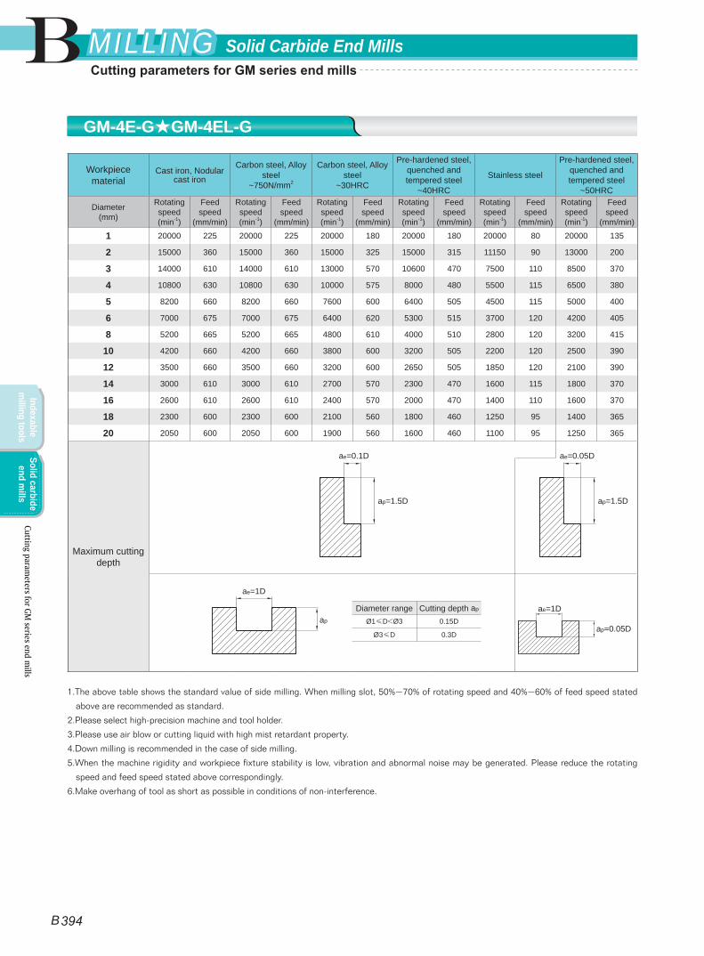
Workpiece material
Cast iron, Nodular cast iron
Carbon steel, Alloy steel
~750N/mm2
Carbon steel, Alloy steel
~30HRC
Pre-hardened steel, quenched and tempered steel
~40HRC
Stainless steel
Pre-hardened steel, quenched and tempered steel
~50HRC
Diameter(mm)
Rotating speed(min-1)
Feed speed
(mm/min)
Rotating speed(min-1)
Feed speed
(mm/min)
Rotating speed(min-1)
Feed speed
(mm/min)
Rotating speed(min-1)
Feed speed
(mm/min)
Rotating speed(min-1)
Feed speed
(mm/min)
Rotating speed(min-1)
Feed speed
(mm/min)
1 20000 225 20000 225 20000 180 20000 180 20000 80 20000 135
2 15000 360 15000 360 15000 325 15000 315 11150 90 13000 200
3 14000 610 14000 610 13000 570 10600 470 7500 110 8500 370
4 10800 630 10800 630 10000 575 8000 480 5500 115 6500 380
5 8200 660 8200 660 7600 600 6400 505 4500 115 5000 400
6 7000 675 7000 675 6400 620 5300 515 3700 120 4200 405
8 5200 665 5200 665 4800 610 4000 510 2800 120 3200 415
10 4200 660 4200 660 3800 600 3200 505 2200 120 2500 390
12 3500 660 3500 660 3200 600 2650 505 1850 120 2100 390
14 3000 610 3000 610 2700 570 2300 470 1600 115 1800 370
16 2600 610 2600 610 2400 570 2000 470 1400 110 1600 370
18 2300 600 2300 600 2100 560 1800 460 1250 95 1400 365
20 2050 600 2050 600 1900 560 1600 460 1100 95 1250 365
Maximum cutting depth
1.The above table shows the standard value of side milling. When milling slot, 50%~70% of rotating speed and 40%~60% of feed speed stated
above are recommended as standard.
2.Please select high-precision machine and tool holder.
3.Please use air blow or cutting liquid with high mist retardant property.
4.Down milling is recommended in the case of side milling.
5.When the machine rigidity and workpiece fixture stability is low, vibration and abnormal noise may be generated. Please reduce the rotating
speed and feed speed stated above correspondingly.
6.Make overhang of tool as short as possible in conditions of non-interference.
Diameter range Cutting depth ap
Ø1≤D<Ø3 0.15D
Ø3≤D 0.3D
ae=1D
ap
ae=1D
ap=0.05D
ae=0.1D
ap=1.5D
ae=0.05D
ap=1.5D
GM-4E-G★GM-4EL-G
Cutting parameters for GM
series end mills
B 394
B Solid Carbide End MillsMILLINGMILLING
Indexable m
illing toolsSolid carbide
end mills
Cutting parameters for GM series end mills
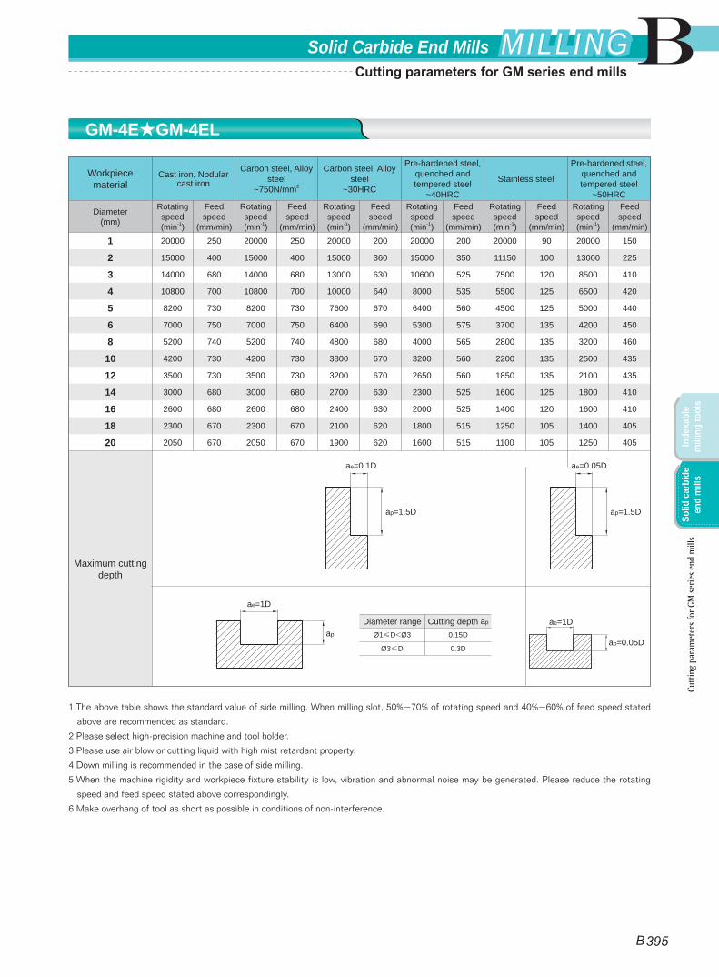
Workpiece material
Cast iron, Nodular cast iron
Carbon steel, Alloy steel
~750N/mm2
Carbon steel, Alloy steel
~30HRC
Pre-hardened steel, quenched and tempered steel
~40HRC
Stainless steel
Pre-hardened steel, quenched and tempered steel
~50HRC
Diameter(mm)
Rotating speed(min-1)
Feed speed
(mm/min)
Rotating speed(min-1)
Feed speed
(mm/min)
Rotating speed(min-1)
Feed speed
(mm/min)
Rotating speed(min-1)
Feed speed
(mm/min)
Rotating speed(min-1)
Feed speed
(mm/min)
Rotating speed(min-1)
Feed speed
(mm/min)
1 20000 250 20000 250 20000 200 20000 200 20000 90 20000 150
2 15000 400 15000 400 15000 360 15000 350 11150 100 13000 225
3 14000 680 14000 680 13000 630 10600 525 7500 120 8500 410
4 10800 700 10800 700 10000 640 8000 535 5500 125 6500 420
5 8200 730 8200 730 7600 670 6400 560 4500 125 5000 440
6 7000 750 7000 750 6400 690 5300 575 3700 135 4200 450
8 5200 740 5200 740 4800 680 4000 565 2800 135 3200 460
10 4200 730 4200 730 3800 670 3200 560 2200 135 2500 435
12 3500 730 3500 730 3200 670 2650 560 1850 135 2100 435
14 3000 680 3000 680 2700 630 2300 525 1600 125 1800 410
16 2600 680 2600 680 2400 630 2000 525 1400 120 1600 410
18 2300 670 2300 670 2100 620 1800 515 1250 105 1400 405
20 2050 670 2050 670 1900 620 1600 515 1100 105 1250 405
Maximum cutting depth
1.The above table shows the standard value of side milling. When milling slot, 50%~70% of rotating speed and 40%~60% of feed speed stated
above are recommended as standard.
2.Please select high-precision machine and tool holder.
3.Please use air blow or cutting liquid with high mist retardant property.
4.Down milling is recommended in the case of side milling.
5.When the machine rigidity and workpiece fixture stability is low, vibration and abnormal noise may be generated. Please reduce the rotating
speed and feed speed stated above correspondingly.
6.Make overhang of tool as short as possible in conditions of non-interference.
Diameter range Cutting depth ap
Ø1≤D<Ø3 0.15D
Ø3≤D 0.3D
ae=1D
ap
ae=1D
ap=0.05D
ae=0.1D
ap=1.5D
ae=0.05D
ap=1.5D
GM-4E★GM-4EL
Cutt
ing
para
met
ers f
or G
M se
ries e
nd m
ills
B 395
BSolid Carbide End Mills MILLINGMILLING
Inde
xabl
e m
illin
g to
ols
Solid
car
bide
en
d m
ills
Cutting parameters for GM series end mills
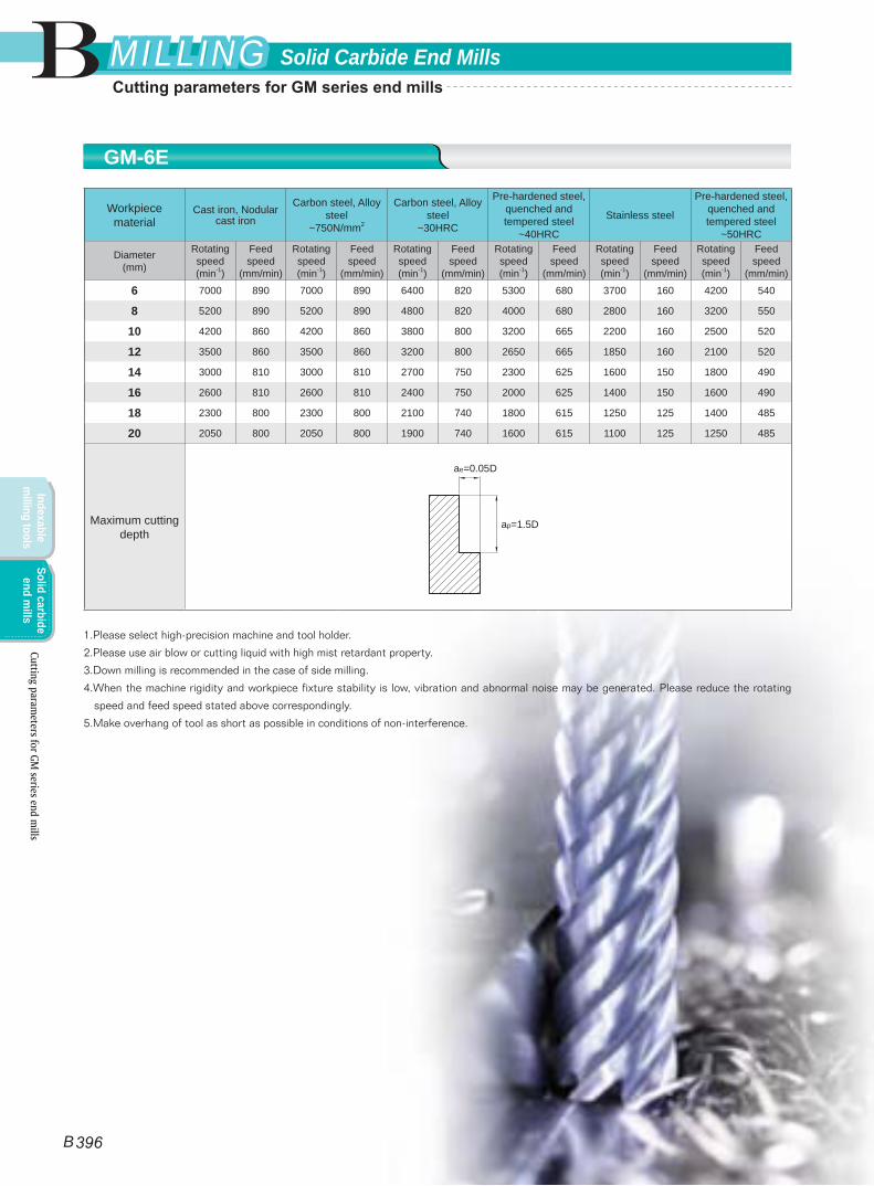
Workpiece material
Cast iron, Nodular cast iron
Carbon steel, Alloy steel
~750N/mm2
Carbon steel, Alloy steel
~30HRC
Pre-hardened steel, quenched and tempered steel
~40HRC
Stainless steel
Pre-hardened steel, quenched and tempered steel
~50HRC
Diameter(mm)
Rotating speed(min-1)
Feed speed
(mm/min)
Rotating speed(min-1)
Feed speed
(mm/min)
Rotating speed(min-1)
Feed speed
(mm/min)
Rotating speed(min-1)
Feed speed
(mm/min)
Rotating speed(min-1)
Feed speed
(mm/min)
Rotating speed(min-1)
Feed speed
(mm/min)
6 7000 890 7000 890 6400 820 5300 680 3700 160 4200 540
8 5200 890 5200 890 4800 820 4000 680 2800 160 3200 550
10 4200 860 4200 860 3800 800 3200 665 2200 160 2500 520
12 3500 860 3500 860 3200 800 2650 665 1850 160 2100 520
14 3000 810 3000 810 2700 750 2300 625 1600 150 1800 490
16 2600 810 2600 810 2400 750 2000 625 1400 150 1600 490
18 2300 800 2300 800 2100 740 1800 615 1250 125 1400 485
20 2050 800 2050 800 1900 740 1600 615 1100 125 1250 485
Maximum cutting depth
1.Please select high-precision machine and tool holder.
2.Please use air blow or cutting liquid with high mist retardant property.
3.Down milling is recommended in the case of side milling.
4.When the machine rigidity and workpiece fixture stability is low, vibration and abnormal noise may be generated. Please reduce the rotating
speed and feed speed stated above correspondingly.
5.Make overhang of tool as short as possible in conditions of non-interference.
ae=0.05D
ap=1.5D
GM-6E
Cutting parameters for GM
series end mills
B 396
B Solid Carbide End MillsMILLINGMILLING
Indexable m
illing toolsSolid carbide
end mills
Cutting parameters for GM series end mills
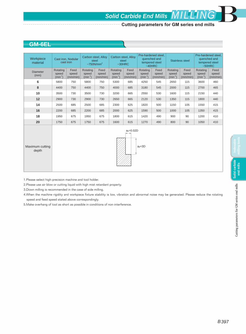
Workpiece material
Cast iron, Nodular cast iron
Carbon steel, Alloy steel
~750N/mm2
Carbon steel, Alloy steel
~30HRC
Pre-hardened steel, quenched and tempered steel
~40HRC
Stainless steel
Pre-hardened steel, quenched and tempered steel
~50HRC
Diameter(mm)
Rotating speed(min-1)
Feed speed
(mm/min)
Rotating speed(min-1)
Feed speed
(mm/min)
Rotating speed(min-1)
Feed speed
(mm/min)
Rotating speed(min-1)
Feed speed
(mm/min)
Rotating speed(min-1)
Feed speed
(mm/min)
Rotating speed(min-1)
Feed speed
(mm/min)
6 5800 750 5800 750 5300 685 4250 545 2650 115 3600 460
8 4400 750 4400 750 4000 685 3180 545 2000 115 2700 465
10 3500 730 3500 730 3200 665 2550 530 1600 115 2150 440
12 2900 730 2900 730 2650 665 2120 530 1350 115 1800 440
14 2500 685 2500 685 2300 625 1820 500 1150 105 1550 415
16 2200 685 2200 685 2000 625 1590 500 1000 105 1350 415
18 1950 675 1950 675 1800 615 1420 490 900 90 1200 410
20 1750 675 1750 675 1600 615 1270 490 800 90 1050 410
Maximum cutting depth
1.Please select high-precision machine and tool holder.
2.Please use air blow or cutting liquid with high mist retardant property.
3.Down milling is recommended in the case of side milling.
4.When the machine rigidity and workpiece fixture stability is low, vibration and abnormal noise may be generated. Please reduce the rotating
speed and feed speed stated above correspondingly.
5.Make overhang of tool as short as possible in conditions of non-interference.
ae=0.02D
ap=3D
GM-6EL
Cutt
ing
para
met
ers f
or G
M se
ries e
nd m
ills
B 397
BSolid Carbide End Mills MILLINGMILLING
Inde
xabl
e m
illin
g to
ols
Solid
car
bide
en
d m
ills
Cutting parameters for GM series end mills
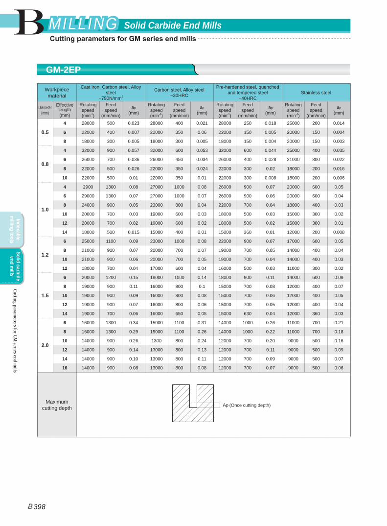
Workpiece material
Cast iron, Carbon steel, Alloy steel
~750N/mm2
Carbon steel, Alloy steel~30HRC
Pre-hardened steel, quenched and tempered steel
~40HRCStainless steel
Diameter(mm)
Effective length(mm)
Rotating speed(min-1)
Feed speed
(mm/min)
ap
(mm)
Rotating speed(min-1)
Feed speed
(mm/min)
ap
(mm)
Rotating speed(min-1)
Feed speed
(mm/min)
ap
(mm)
Rotating speed(min-1)
Feed speed
(mm/min)
ap
(mm)
0.5
4 28000 500 0.023 28000 400 0.021 28000 250 0.018 25000 200 0.014
6 22000 400 0.007 22000 350 0.06 22000 150 0.005 20000 150 0.004
8 18000 300 0.005 18000 300 0.005 18000 150 0.004 20000 150 0.003
0.8
4 32000 900 0.057 32000 600 0.053 32000 600 0.044 25000 400 0.035
6 26000 700 0.036 26000 450 0.034 26000 400 0.028 21000 300 0.022
8 22000 500 0.026 22000 350 0.024 22000 300 0.02 18000 200 0.016
10 22000 500 0.01 22000 350 0.01 22000 300 0.008 18000 200 0.006
1.0
4 2900 1300 0.08 27000 1000 0.08 26000 900 0.07 20000 600 0.05
6 29000 1300 0.07 27000 1000 0.07 26000 900 0.06 20000 600 0.04
8 24000 900 0.05 23000 800 0.04 22000 700 0.04 18000 400 0.03
10 20000 700 0.03 19000 600 0.03 18000 500 0.03 15000 300 0.02
12 20000 700 0.02 19000 600 0.02 18000 500 0.02 15000 300 0.01
14 18000 500 0.015 15000 400 0.01 15000 360 0.01 12000 200 0.008
1.2
6 25000 1100 0.09 23000 1000 0.08 22000 900 0.07 17000 600 0.05
8 21000 900 0.07 20000 700 0.07 19000 700 0.05 14000 400 0.04
10 21000 900 0.06 20000 700 0.05 19000 700 0.04 14000 400 0.03
12 18000 700 0.04 17000 600 0.04 16000 500 0.03 11000 300 0.02
1.5
6 20000 1200 0.15 18000 1000 0.14 18000 900 0.11 14000 600 0.09
8 19000 900 0.11 16000 800 0.1 15000 700 0.08 12000 400 0.07
10 19000 900 0.09 16000 800 0.08 15000 700 0.06 12000 400 0.05
12 19000 900 0.07 16000 800 0.06 15000 700 0.05 12000 400 0.04
14 19000 700 0.06 16000 650 0.05 15000 630 0.04 12000 360 0.03
2.0
6 16000 1300 0.34 15000 1100 0.31 14000 1000 0.26 11000 700 0.21
8 16000 1300 0.29 15000 1100 0.26 14000 1000 0.22 11000 700 0.18
10 14000 900 0.26 1300 800 0.24 12000 700 0.20 9000 500 0.16
12 14000 900 0.14 13000 800 0.13 12000 700 0.11 9000 500 0.09
14 14000 900 0.10 13000 800 0.11 12000 700 0.09 9000 500 0.07
16 14000 900 0.08 13000 800 0.08 12000 700 0.07 9000 500 0.06
Maximum cutting depth
(Once cutting depth)
GM-2EP
Cutting parameters for GM
series end mills
B 398
B Solid Carbide End MillsMILLINGMILLING
Indexable m
illing toolsSolid carbide
end mills
Cutting parameters for GM series end mills
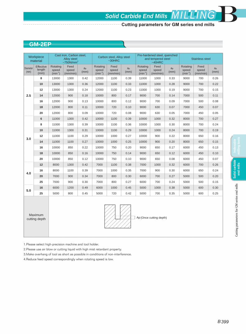
Workpiece material
Cast iron, Carbon steel, Alloy steel
~750N/mm2
Carbon steel, Alloy steel~30HRC
Pre-hardened steel, quenched and tempered steel
~40HRCStainless steel
Diameter(mm)
Effective length(mm)
Rotating speed(min-1)
Feed speed
(mm/min)
ap
(mm)
Rotating speed(min-1)
Feed speed
(mm/min)
ap
(mm)
Rotating speed(min-1)
Feed speed
(mm/min)
ap
(mm)
Rotating speed(min-1)
Feed speed
(mm/min)
ap
(mm)
2.5
8 13000 1300 0.42 12000 1100 0.39 11000 1000 0.33 9000 700 0.26
10 13000 1300 0.36 12000 1100 0.33 11000 1000 0.28 9000 700 0.22
12 13000 1300 0.24 12000 1100 0.23 11000 1000 0.19 9000 700 0.15
14 12000 900 0.18 10000 800 0.17 9000 700 0.14 7000 500 0.11
16 12000 900 0.13 10000 800 0.12 9000 700 0.09 7000 500 0.08
18 12000 800 0.11 10000 720 0.10 9000 630 0.07 7000 450 0.07
20 12000 800 0.09 10000 720 0.08 9000 630 0.05 7000 450 0.05
3.0
6 11000 1300 0.42 10000 1100 0.39 10000 1000 0.32 8000 700 0.27
8 11000 1300 0.39 10000 1100 0.36 10000 1000 0.30 8000 700 0.24
10 11000 1300 0.31 10000 1100 0.29 10000 1000 0.24 8000 700 0.19
12 11000 1100 0.29 10000 1000 0.27 10000 900 0.22 8000 650 0.16
14 11000 1100 0.27 10000 1000 0.25 10000 900 0.20 8000 650 0.15
16 10000 850 0.22 10000 750 0.20 9000 650 0.17 6000 450 0.13
18 10000 850 0.16 10000 750 0.14 9000 650 0.12 6000 450 0.10
20 10000 850 0.12 10000 750 0.10 9000 650 0.08 6000 450 0.07
4.0
12 8000 1300 0.42 7000 1100 0.38 7000 1000 0.32 6000 700 0.26
16 8000 1100 0.39 7000 1000 0.35 7000 900 0.30 6000 650 0.24
20 7000 900 0.34 7000 800 0.30 6000 700 0.27 5000 500 0.20
25 7000 900 0.30 7000 800 0.27 6000 700 0.24 5000 500 0.15
5.016 6000 1200 0.49 6000 1000 0.45 5000 1000 0.38 5000 600 0.30
25 5000 800 0.45 5000 720 0.42 5000 700 0.35 5000 600 0.25
Maximum cutting depth
1.Please select high-precision machine and tool holder.
2.Please use air blow or cutting liquid with high mist retardant property.
3.Make overhang of tool as short as possible in conditions of non-interference.
4.Reduce feed speed correspondingly when rotating speed is low.
(Once cutting depth)
GM-2EP
Cutt
ing
para
met
ers f
or G
M se
ries e
nd m
ills
B 399
BSolid Carbide End Mills MILLINGMILLING
Inde
xabl
e m
illin
g to
ols
Solid
car
bide
en
d m
ills
Cutting parameters for GM series end mills
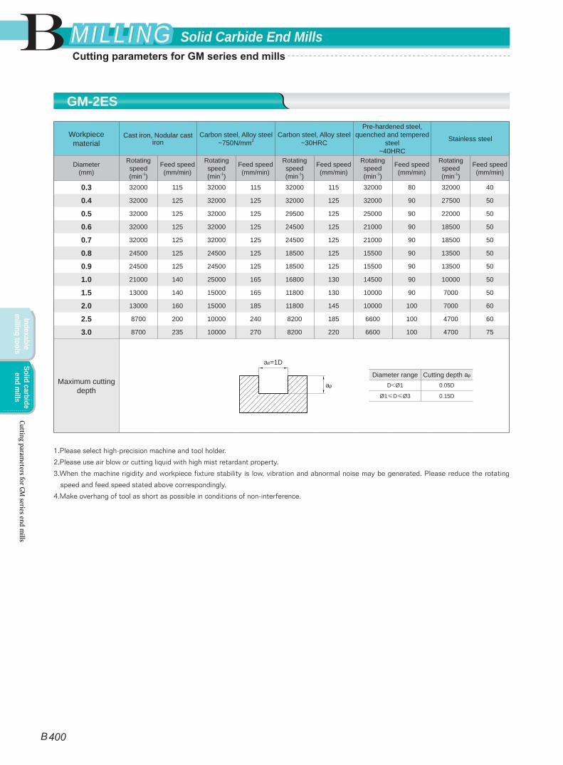
Workpiece material
Cast iron, Nodular cast iron
Carbon steel, Alloy steel~750N/mm2
Carbon steel, Alloy steel~30HRC
Pre-hardened steel, quenched and tempered
steel~40HRC
Stainless steel
Diameter(mm)
Rotating speed(min-1)
Feed speed(mm/min)
Rotating speed(min-1)
Feed speed(mm/min)
Rotating speed(min-1)
Feed speed(mm/min)
Rotating speed(min-1)
Feed speed(mm/min)
Rotating speed(min-1)
Feed speed(mm/min)
0.3 32000 115 32000 115 32000 115 32000 80 32000 40
0.4 32000 125 32000 125 32000 125 32000 90 27500 50
0.5 32000 125 32000 125 29500 125 25000 90 22000 50
0.6 32000 125 32000 125 24500 125 21000 90 18500 50
0.7 32000 125 32000 125 24500 125 21000 90 18500 50
0.8 24500 125 24500 125 18500 125 15500 90 13500 50
0.9 24500 125 24500 125 18500 125 15500 90 13500 50
1.0 21000 140 25000 165 16800 130 14500 90 10000 50
1.5 13000 140 15000 165 11800 130 10000 90 7000 50
2.0 13000 160 15000 185 11800 145 10000 100 7000 60
2.5 8700 200 10000 240 8200 185 6600 100 4700 60
3.0 8700 235 10000 270 8200 220 6600 100 4700 75
Maximum cutting depth
1.Please select high-precision machine and tool holder.
2.Please use air blow or cutting liquid with high mist retardant property.
3.When the machine rigidity and workpiece fixture stability is low, vibration and abnormal noise may be generated. Please reduce the rotating
speed and feed speed stated above correspondingly.
4.Make overhang of tool as short as possible in conditions of non-interference.
Diameter range Cutting depth ap
D<Ø1 0.05D
Ø1≤D≤Ø3 0.15D
ae=1D
ap
GM-2ES
Cutting parameters for GM
series end mills
B 400
B Solid Carbide End MillsMILLINGMILLING
Indexable m
illing toolsSolid carbide
end mills
Cutting parameters for GM series end mills
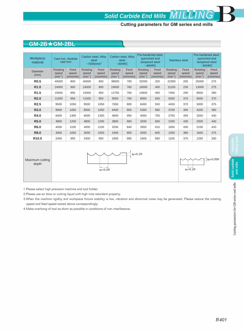
Workpiece material
Cast iron, Nodular cast iron
Carbon steel, Alloy steel
~750N/mm2
Carbon steel, Alloy steel
~30HRC
Pre-hardened steel, quenched and tempered steel
~40HRC
Stainless steel
Pre-hardened steel, quenched and tempered steel
~50HRC
Diameter(mm)
Rotating speed(min-1)
Feed speed
(mm/min)
Rotating speed(min-1)
Feed speed
(mm/min)
Rotating speed(min-1)
Feed speed
(mm/min)
Rotating speed(min-1)
Feed speed
(mm/min)
Rotating speed(min-1)
Feed speed
(mm/min)
Rotating speed(min-1)
Feed speed
(mm/min)
R0.5 40000 800 40000 800 38000 700 32000 320 22300 200 25000 275
R1.0 24000 900 24000 900 19000 760 16000 400 11150 230 13000 275
R1.5 15500 950 15500 950 12750 760 10600 450 7400 290 8500 280
R2.0 11500 950 11500 950 9550 760 8000 550 5550 370 6500 370
R2.5 9500 1050 9500 1050 7650 800 6400 550 4450 370 5000 375
R3.0 8000 1050 8000 1050 6400 800 5300 580 3700 390 4200 390
R4.0 6000 1300 6000 1300 4800 950 4000 700 2750 455 3200 440
R5.0 4800 1200 4800 1200 3800 900 3200 650 2200 430 2500 440
R6.0 4000 1100 4000 1100 3200 840 2650 610 1850 430 2100 420
R8.0 3000 1050 3000 1050 2400 800 2000 600 1350 380 1600 375
R10.0 2400 950 2400 950 1900 680 1600 560 1100 370 1250 330
Maximum cutting depth
1.Please select high-precision machine and tool holder.
2.Please use air blow or cutting liquid with high mist retardant property.
3.When the machine rigidity and workpiece fixture stability is low, vibration and abnormal noise may be generated. Please reduce the rotating
speed and feed speed stated above correspondingly.
4.Make overhang of tool as short as possible in conditions of non-interference.
ae=0.2R
ap=0.1R
ae=0.1R
ap=0.05R
GM-2B★GM-2BL
Cutt
ing
para
met
ers f
or G
M se
ries e
nd m
ills
B 401
BSolid Carbide End Mills MILLINGMILLING
Inde
xabl
e m
illin
g to
ols
Solid
car
bide
en
d m
ills
Cutting parameters for GM series end mills
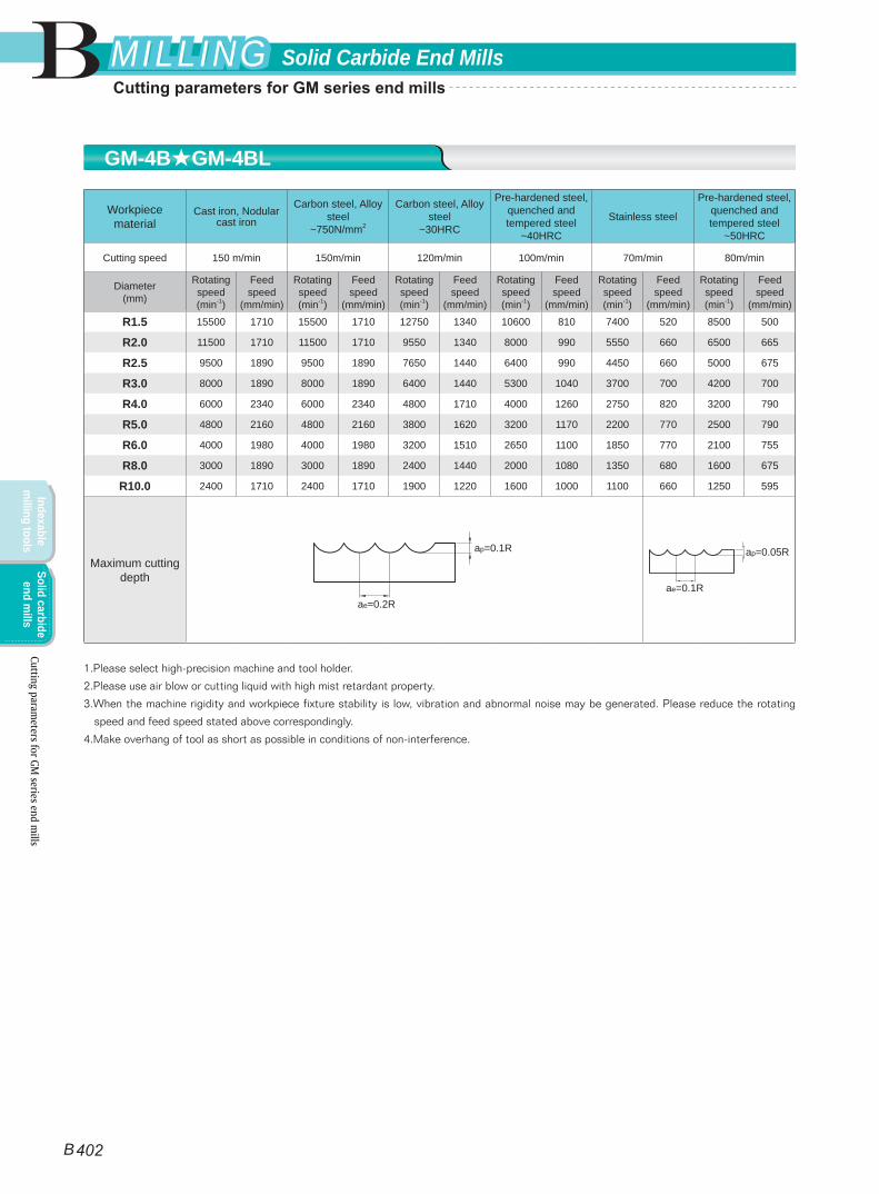
Workpiece material
Cast iron, Nodular cast iron
Carbon steel, Alloy steel
~750N/mm2
Carbon steel, Alloy steel
~30HRC
Pre-hardened steel, quenched and tempered steel
~40HRC
Stainless steel
Pre-hardened steel, quenched and tempered steel
~50HRC
Cutting speed 150 m/min 150m/min 120m/min 100m/min 70m/min 80m/min
Diameter(mm)
Rotating speed(min-1)
Feed speed
(mm/min)
Rotating speed(min-1)
Feed speed
(mm/min)
Rotating speed(min-1)
Feed speed
(mm/min)
Rotating speed(min-1)
Feed speed
(mm/min)
Rotating speed(min-1)
Feed speed
(mm/min)
Rotating speed(min-1)
Feed speed
(mm/min)
R1.5 15500 1710 15500 1710 12750 1340 10600 810 7400 520 8500 500
R2.0 11500 1710 11500 1710 9550 1340 8000 990 5550 660 6500 665
R2.5 9500 1890 9500 1890 7650 1440 6400 990 4450 660 5000 675
R3.0 8000 1890 8000 1890 6400 1440 5300 1040 3700 700 4200 700
R4.0 6000 2340 6000 2340 4800 1710 4000 1260 2750 820 3200 790
R5.0 4800 2160 4800 2160 3800 1620 3200 1170 2200 770 2500 790
R6.0 4000 1980 4000 1980 3200 1510 2650 1100 1850 770 2100 755
R8.0 3000 1890 3000 1890 2400 1440 2000 1080 1350 680 1600 675
R10.0 2400 1710 2400 1710 1900 1220 1600 1000 1100 660 1250 595
Maximum cutting depth
1.Please select high-precision machine and tool holder.
2.Please use air blow or cutting liquid with high mist retardant property.
3.When the machine rigidity and workpiece fixture stability is low, vibration and abnormal noise may be generated. Please reduce the rotating
speed and feed speed stated above correspondingly.
4.Make overhang of tool as short as possible in conditions of non-interference.
ae=0.2R
ap=0.1R
ae=0.1R
ap=0.05R
GM-4B★GM-4BL
Cutting parameters for GM
series end mills
B 402
B Solid Carbide End MillsMILLINGMILLING
Indexable m
illing toolsSolid carbide
end mills
Cutting parameters for GM series end mills
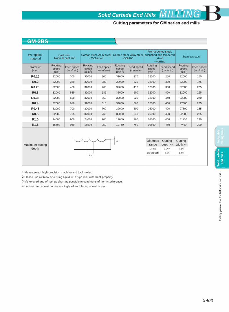
Workpiece material
Cast iron, Nodular cast iron
Carbon steel, Alloy steel~750N/mm2
Carbon steel, Alloy steel~30HRC
Pre-hardened steel, quenched and tempered
steel~40HRC
Stainless steel
Diameter(mm)
Rotating speed(min-1)
Feed speed(mm/min)
Rotating speed(min-1)
Feed speed(mm/min)
Rotating speed(min-1)
Feed speed(mm/min)
Rotating speed(min-1)
Feed speed(mm/min)
Rotating speed(min-1)
Feed speed(mm/min)
R0.15 32000 300 32000 300 32000 270 32000 250 32000 150
R0.2 32000 380 32000 380 32000 320 32000 300 32000 175
R0.25 32000 460 32000 460 32000 410 32000 330 32000 205
R0.3 32000 535 32000 535 32000 500 32000 420 32000 265
R0.35 32000 550 32000 550 32000 520 32000 440 32000 270
R0.4 32000 610 32000 610 32000 560 32000 460 27500 285
R0.45 32000 700 32000 700 32000 600 25000 400 27500 285
R0.5 32000 765 32000 765 32000 640 25000 400 22000 285
R1.0 24000 900 24000 900 19000 760 16000 400 11150 230
R1.5 15500 950 15500 950 12750 760 10600 450 7400 290
Maximum cutting depth
1.Please select high-precision machine and tool holder.
2.Please use air blow or cutting liquid with high mist retardant property.
3.Make overhang of tool as short as possible in conditions of non-interference.
4.Reduce feed speed correspondingly when rotating speed is low.
Diameter range
Cutting depth ap
Cutting width ae
D<Ø1 0.05R 0.2R
Ø1≤D≤Ø3 0.1R 0.2R
ae
ap
GM-2BS
Cutt
ing
para
met
ers f
or G
M se
ries e
nd m
ills
B 403
BSolid Carbide End Mills MILLINGMILLING
Inde
xabl
e m
illin
g to
ols
Solid
car
bide
en
d m
ills
Cutting parameters for GM series end mills
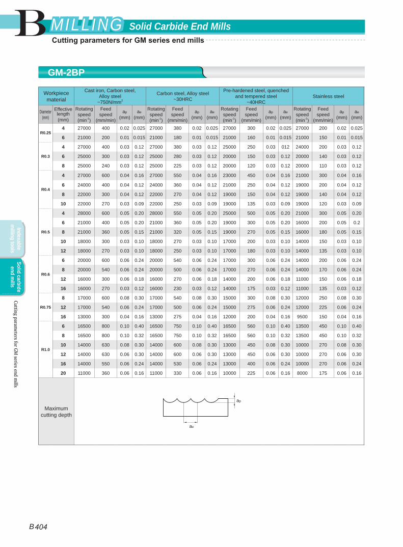
Workpiece material
Cast iron, Carbon steel, Alloy steel
~750N/mm2
Carbon steel, Alloy steel~30HRC
Pre-hardened steel, quenched and tempered steel
~40HRCStainless steel
Diameter(mm)
Effective length(mm)
Rotating speed(min-1)
Feed speed
(mm/min)
ap
(mm)ae
(mm)
Rotating speed(min-1)
Feed speed
(mm/min)
ap
(mm)ae
(mm)
Rotating speed(min-1)
Feed speed
(mm/min)
ap
(mm)ae
(mm)
Rotating speed(min-1)
Feed speed
(mm/min)
ap
(mm)ae
(mm)
R0.254 27000 400 0.02 0.025 27000 380 0.02 0.025 27000 300 0.02 0.025 27000 200 0.02 0.025
6 21000 200 0.01 0.015 21000 180 0.01 0.015 21000 160 0.01 0.015 21000 150 0.01 0.015
R0.3
4 27000 400 0.03 0.12 27000 380 0.03 0.12 25000 250 0.03 012 24000 200 0.03 0.12
6 25000 300 0.03 0.12 25000 280 0.03 0.12 20000 150 0.03 0.12 20000 140 0.03 0.12
8 25000 240 0.03 0.12 25000 225 0.03 0.12 20000 120 0.03 0.12 20000 110 0.03 0.12
R0.4
4 27000 600 0.04 0.16 27000 550 0.04 0.16 23000 450 0.04 0.16 21000 300 0.04 0.16
6 24000 400 0.04 0.12 24000 360 0.04 0.12 21000 250 0.04 0.12 19000 200 0.04 0.12
8 22000 300 0.04 0.12 22000 270 0.04 0.12 19000 150 0.04 0.12 19000 140 0.04 0.12
10 22000 270 0.03 0.09 22000 250 0.03 0.09 19000 135 0.03 0.09 19000 120 0.03 0.09
R0.5
4 28000 600 0.05 0.20 28000 550 0.05 0.20 25000 500 0.05 0.20 21000 300 0.05 0.20
6 21000 400 0.05 0.20 21000 360 0.05 0.20 19000 300 0.05 0.20 16000 200 0.05 0.2
8 21000 360 0.05 0.15 21000 320 0.05 0.15 19000 270 0.05 0.15 16000 180 0.05 0.15
10 18000 300 0.03 0.10 18000 270 0.03 0.10 17000 200 0.03 0.10 14000 150 0.03 0.10
12 18000 270 0.03 0.10 18000 250 0.03 0.10 17000 180 0.03 0.10 14000 135 0.03 0.10
R0.6
6 20000 600 0.06 0.24 20000 540 0.06 0.24 17000 300 0.06 0.24 14000 200 0.06 0.24
8 20000 540 0.06 0.24 20000 500 0.06 0.24 17000 270 0.06 0.24 14000 170 0.06 0.24
12 16000 300 0.06 0.18 16000 270 0.06 0.18 14000 200 0.06 0.18 11000 150 0.06 0.18
16 16000 270 0.03 0.12 16000 230 0.03 0.12 14000 175 0.03 0.12 11000 135 0.03 0.12
R0.75
8 17000 600 0.08 0.30 17000 540 0.08 0.30 15000 300 0.08 0.30 12000 250 0.08 0.30
12 17000 540 0.06 0.24 17000 500 0.06 0.24 15000 275 0.06 0.24 12000 225 0.06 0.24
16 13000 300 0.04 0.16 13000 275 0.04 0.16 12000 200 0.04 0.16 9500 150 0.04 0.16
R1.0
6 16500 800 0.10 0.40 16500 750 0.10 0.40 16500 560 0.10 0.40 13500 450 0.10 0.40
8 16500 800 0.10 0.32 16500 750 0.10 0.32 16500 560 0.10 0.32 13500 450 0.10 0.32
10 14000 630 0.08 0.30 14000 600 0.08 0.30 13000 450 0.08 0.30 10000 270 0.08 0.30
12 14000 630 0.06 0.30 14000 600 0.06 0.30 13000 450 0.06 0.30 10000 270 0.06 0.30
16 14000 550 0.06 0.24 14000 530 0.06 0.24 13000 400 0.06 0.24 10000 270 0.06 0.24
20 11000 360 0.06 0.16 11000 330 0.06 0.16 10000 225 0.06 0.16 8000 175 0.06 0.16
Maximum cutting depth
ae
ap
GM-2BP
Cutting parameters for GM
series end mills
B 404
B Solid Carbide End MillsMILLINGMILLING
Indexable m
illing toolsSolid carbide
end mills
Cutting parameters for GM series end mills
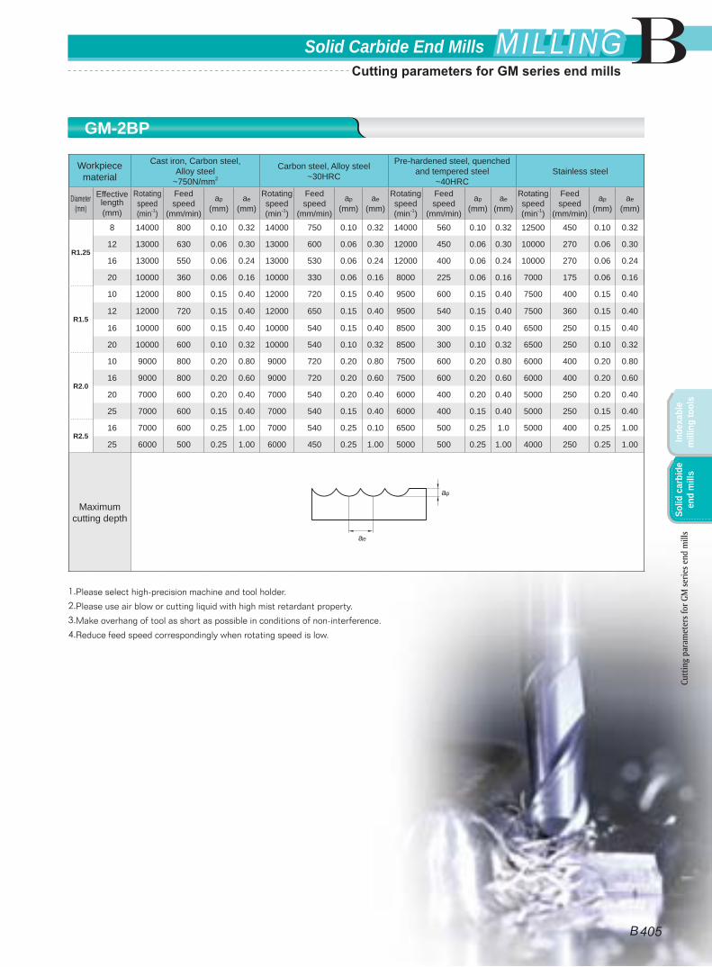
Workpiece material
Cast iron, Carbon steel, Alloy steel
~750N/mm2
Carbon steel, Alloy steel~30HRC
Pre-hardened steel, quenched and tempered steel
~40HRCStainless steel
Diameter(mm)
Effective length(mm)
Rotating speed(min-1)
Feed speed
(mm/min)
ap
(mm)ae
(mm)
Rotating speed(min-1)
Feed speed
(mm/min)
ap
(mm)ae
(mm)
Rotating speed(min-1)
Feed speed
(mm/min)
ap
(mm)ae
(mm)
Rotating speed(min-1)
Feed speed
(mm/min)
ap
(mm)ae
(mm)
R1.25
8 14000 800 0.10 0.32 14000 750 0.10 0.32 14000 560 0.10 0.32 12500 450 0.10 0.32
12 13000 630 0.06 0.30 13000 600 0.06 0.30 12000 450 0.06 0.30 10000 270 0.06 0.30
16 13000 550 0.06 0.24 13000 530 0.06 0.24 12000 400 0.06 0.24 10000 270 0.06 0.24
20 10000 360 0.06 0.16 10000 330 0.06 0.16 8000 225 0.06 0.16 7000 175 0.06 0.16
R1.5
10 12000 800 0.15 0.40 12000 720 0.15 0.40 9500 600 0.15 0.40 7500 400 0.15 0.40
12 12000 720 0.15 0.40 12000 650 0.15 0.40 9500 540 0.15 0.40 7500 360 0.15 0.40
16 10000 600 0.15 0.40 10000 540 0.15 0.40 8500 300 0.15 0.40 6500 250 0.15 0.40
20 10000 600 0.10 0.32 10000 540 0.10 0.32 8500 300 0.10 0.32 6500 250 0.10 0.32
R2.0
10 9000 800 0.20 0.80 9000 720 0.20 0.80 7500 600 0.20 0.80 6000 400 0.20 0.80
16 9000 800 0.20 0.60 9000 720 0.20 0.60 7500 600 0.20 0.60 6000 400 0.20 0.60
20 7000 600 0.20 0.40 7000 540 0.20 0.40 6000 400 0.20 0.40 5000 250 0.20 0.40
25 7000 600 0.15 0.40 7000 540 0.15 0.40 6000 400 0.15 0.40 5000 250 0.15 0.40
R2.516 7000 600 0.25 1.00 7000 540 0.25 0.10 6500 500 0.25 1.0 5000 400 0.25 1.00
25 6000 500 0.25 1.00 6000 450 0.25 1.00 5000 500 0.25 1.00 4000 250 0.25 1.00
Maximum cutting depth
1.Please select high-precision machine and tool holder.
2.Please use air blow or cutting liquid with high mist retardant property.
3.Make overhang of tool as short as possible in conditions of non-interference.
4.Reduce feed speed correspondingly when rotating speed is low.
ae
ap
GM-2BP
Cutt
ing
para
met
ers f
or G
M se
ries e
nd m
ills
B 405
BSolid Carbide End Mills MILLINGMILLING
Inde
xabl
e m
illin
g to
ols
Solid
car
bide
en
d m
ills
Cutting parameters for GM series end mills
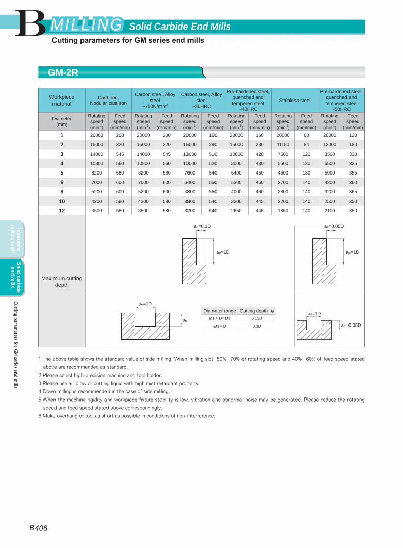
Workpiece material
Cast iron, Nodular cast iron
Carbon steel, Alloy steel
~750N/mm2
Carbon steel, Alloy steel
~30HRC
Pre-hardened steel, quenched and tempered steel
~40HRC
Stainless steel
Pre-hardened steel, quenched and tempered steel
~50HRC
Diameter(mm)
Rotating speed(min-1)
Feed speed
(mm/min)
Rotating speed(min-1)
Feed speed
(mm/min)
Rotating speed(min-1)
Feed speed
(mm/min)
Rotating speed(min-1)
Feed speed
(mm/min)
Rotating speed(min-1)
Feed speed
(mm/min)
Rotating speed(min-1)
Feed speed
(mm/min)
1 20000 200 20000 200 20000 160 20000 160 20000 60 20000 120
2 15000 320 15000 320 15000 290 15000 280 11150 84 13000 180
3 14000 545 14000 545 13000 510 10600 420 7500 120 8500 330
4 10800 560 10800 560 10000 520 8000 430 5500 130 6500 335
5 8200 580 8200 580 7600 540 6400 450 4500 130 5000 355
6 7000 600 7000 600 6400 550 5300 460 3700 140 4200 360
8 5200 600 5200 600 4800 550 4000 460 2800 140 3200 365
10 4200 580 4200 580 3800 540 3200 445 2200 140 2500 350
12 3500 580 3500 580 3200 540 2650 445 1850 140 2100 350
Maximum cutting depth
1.The above table shows the standard value of side milling. When milling slot, 50%~70% of rotating speed and 40%~60% of feed speed stated
above are recommended as standard.
2.Please select high-precision machine and tool holder.
3.Please use air blow or cutting liquid with high mist retardant property.
4.Down milling is recommended in the case of side milling.
5.When the machine rigidity and workpiece fixture stability is low, vibration and abnormal noise may be generated. Please reduce the rotating
speed and feed speed stated above correspondingly.
6.Make overhang of tool as short as possible in conditions of non-interference.
Diameter range Cutting depth ap
Ø1≤D<Ø3 0.15D
Ø3≤D 0.3D
ae=1D
ap
ae=1D
ap=0.05D
ae=0.1D
ap=1D
ae=0.05D
ap=1D
GM-2R
Cutting parameters for GM
series end mills
B 406
B Solid Carbide End MillsMILLINGMILLING
Indexable m
illing toolsSolid carbide
end mills
Cutting parameters for GM series end mills
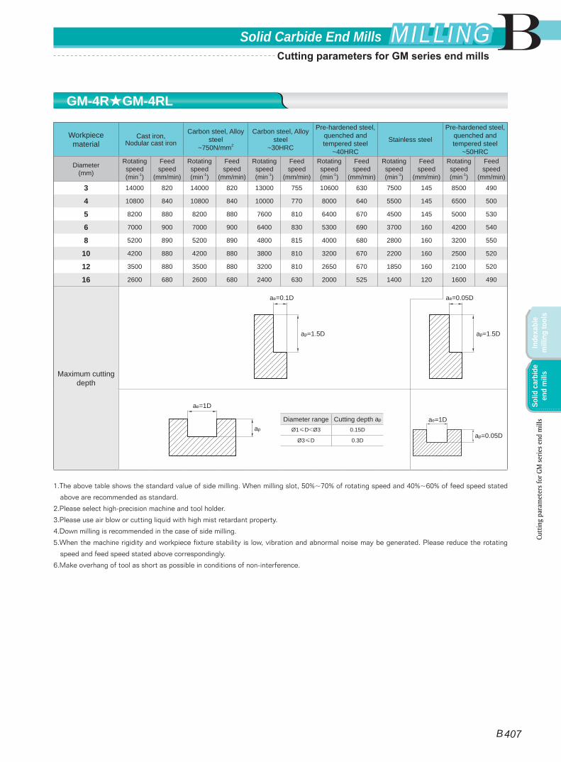
Workpiece material
Cast iron, Nodular cast iron
Carbon steel, Alloy steel
~750N/mm2
Carbon steel, Alloy steel
~30HRC
Pre-hardened steel, quenched and tempered steel
~40HRC
Stainless steel
Pre-hardened steel, quenched and tempered steel
~50HRC
Diameter(mm)
Rotating speed(min-1)
Feed speed
(mm/min)
Rotating speed(min-1)
Feed speed
(mm/min)
Rotating speed(min-1)
Feed speed
(mm/min)
Rotating speed(min-1)
Feed speed
(mm/min)
Rotating speed(min-1)
Feed speed
(mm/min)
Rotating speed(min-1)
Feed speed
(mm/min)
3 14000 820 14000 820 13000 755 10600 630 7500 145 8500 490
4 10800 840 10800 840 10000 770 8000 640 5500 145 6500 500
5 8200 880 8200 880 7600 810 6400 670 4500 145 5000 530
6 7000 900 7000 900 6400 830 5300 690 3700 160 4200 540
8 5200 890 5200 890 4800 815 4000 680 2800 160 3200 550
10 4200 880 4200 880 3800 810 3200 670 2200 160 2500 520
12 3500 880 3500 880 3200 810 2650 670 1850 160 2100 520
16 2600 680 2600 680 2400 630 2000 525 1400 120 1600 490
Maximum cutting depth
1.The above table shows the standard value of side milling. When milling slot, 50%~70% of rotating speed and 40%~60% of feed speed stated
above are recommended as standard.
2.Please select high-precision machine and tool holder.
3.Please use air blow or cutting liquid with high mist retardant property.
4.Down milling is recommended in the case of side milling.
5.When the machine rigidity and workpiece fixture stability is low, vibration and abnormal noise may be generated. Please reduce the rotating
speed and feed speed stated above correspondingly.
6.Make overhang of tool as short as possible in conditions of non-interference.
Diameter range Cutting depth ap
Ø1≤D<Ø3 0.15D
Ø3≤D 0.3D
ae=1D
ap
ae=1D
ap=0.05D
ae=0.1D
ap=1.5D
ae=0.05D
ap=1.5D
GM-4R★GM-4RL
Cutt
ing
para
met
ers f
or G
M se
ries e
nd m
ills
B 407
BSolid Carbide End Mills MILLINGMILLING
Inde
xabl
e m
illin
g to
ols
Solid
car
bide
en
d m
ills
Cutting parameters for GM series end mills
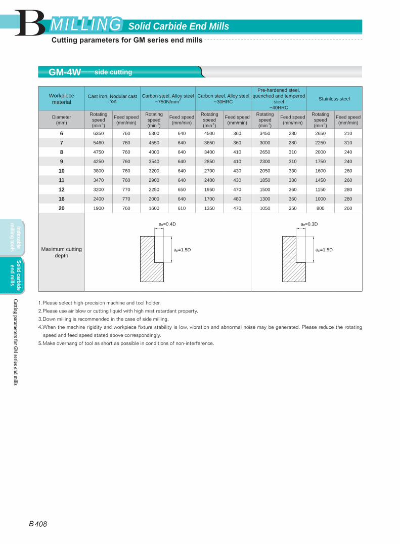
Workpiece material
Cast iron, Nodular cast iron
Carbon steel, Alloy steel~750N/mm2
Carbon steel, Alloy steel~30HRC
Pre-hardened steel, quenched and tempered
steel~40HRC
Stainless steel
Diameter(mm)
Rotating speed(min-1)
Feed speed(mm/min)
Rotating speed(min-1)
Feed speed(mm/min)
Rotating speed(min-1)
Feed speed(mm/min)
Rotating speed(min-1)
Feed speed(mm/min)
Rotating speed(min-1)
Feed speed(mm/min)
6 6350 760 5300 640 4500 360 3450 280 2650 210
7 5460 760 4550 640 3650 360 3000 280 2250 310
8 4750 760 4000 640 3400 410 2650 310 2000 240
9 4250 760 3540 640 2850 410 2300 310 1750 240
10 3800 760 3200 640 2700 430 2050 330 1600 260
11 3470 760 2900 640 2400 430 1850 330 1450 260
12 3200 770 2250 650 1950 470 1500 360 1150 280
16 2400 770 2000 640 1700 480 1300 360 1000 280
20 1900 760 1600 610 1350 470 1050 350 800 260
Maximum cutting depth
1.Please select high-precision machine and tool holder.
2.Please use air blow or cutting liquid with high mist retardant property.
3.Down milling is recommended in the case of side milling.
4.When the machine rigidity and workpiece fixture stability is low, vibration and abnormal noise may be generated. Please reduce the rotating
speed and feed speed stated above correspondingly.
5.Make overhang of tool as short as possible in conditions of non-interference.
ae=0.4D
ap=1.5D
ae=0.3D
ap=1.5D
GM-4W——side cutting
Cutting parameters for GM
series end mills
B 408
B Solid Carbide End MillsMILLINGMILLING
Indexable m
illing toolsSolid carbide
end mills
Cutting parameters for GM series end mills
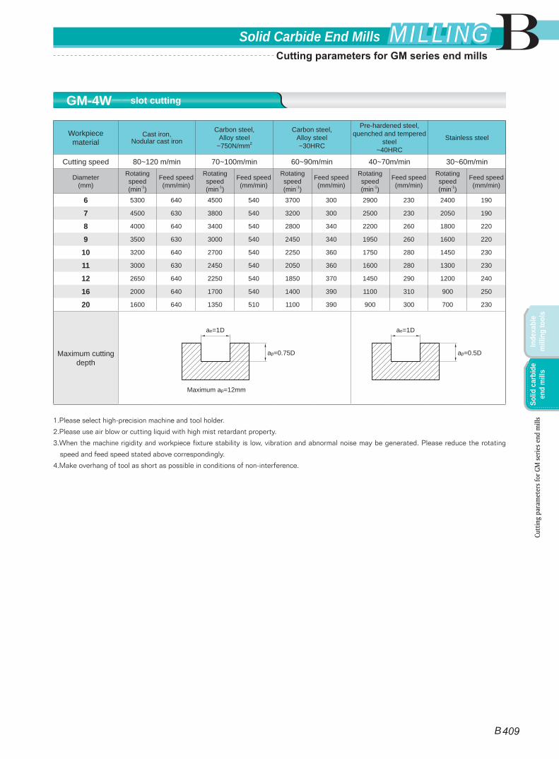
Workpiece material
Cast iron, Nodular cast iron
Carbon steel, Alloy steel
~750N/mm2
Carbon steel, Alloy steel~30HRC
Pre-hardened steel, quenched and tempered
steel~40HRC
Stainless steel
Cutting speed 80~120 m/min 70~100m/min 60~90m/min 40~70m/min 30~60m/min
Diameter(mm)
Rotating speed(min-1)
Feed speed(mm/min)
Rotating speed(min-1)
Feed speed(mm/min)
Rotating speed(min-1)
Feed speed(mm/min)
Rotating speed(min-1)
Feed speed(mm/min)
Rotating speed(min-1)
Feed speed(mm/min)
6 5300 640 4500 540 3700 300 2900 230 2400 190
7 4500 630 3800 540 3200 300 2500 230 2050 190
8 4000 640 3400 540 2800 340 2200 260 1800 220
9 3500 630 3000 540 2450 340 1950 260 1600 220
10 3200 640 2700 540 2250 360 1750 280 1450 230
11 3000 630 2450 540 2050 360 1600 280 1300 230
12 2650 640 2250 540 1850 370 1450 290 1200 240
16 2000 640 1700 540 1400 390 1100 310 900 250
20 1600 640 1350 510 1100 390 900 300 700 230
Maximum cutting depth
1.Please select high-precision machine and tool holder.
2.Please use air blow or cutting liquid with high mist retardant property.
3.When the machine rigidity and workpiece fixture stability is low, vibration and abnormal noise may be generated. Please reduce the rotating
speed and feed speed stated above correspondingly.
4.Make overhang of tool as short as possible in conditions of non-interference.
Maximum ap=12mm
ae=1D
ap=0.75D
ae=1D
ap=0.5D
GM-4W——slot cutting
Cutt
ing
para
met
ers f
or G
M se
ries e
nd m
ills
B 409
BSolid Carbide End Mills MILLINGMILLING
Inde
xabl
e m
illin
g to
ols
Solid
car
bide
en
d m
ills
Cutting parameters for GM series end mills

Workpiece material
Pre-hardened steel, Hardened steel40~50HRC
Hardened steel50~60HRC
Hardened steel60~68HRC
Diameter(mm)
Rotating speed(min-1)
Feed speed(mm/min)
Rotating speed(min-1)
Feed speed(mm/min)
Rotating speed(min-1)
Feed speed(mm/min)
1 40000 160 40000 160 32000 130
2 40000 400 24000 240 16000 160
3 32000 510 16000 255 11000 175
4 24000 625 12000 310 8000 210
5 19000 685 9500 340 6400 230
6 16000 770 8000 385 5300 255
8 12000 770 6000 385 4000 255
10 9600 770 4800 385 3200 255
12 8000 800 4000 400 2700 270
14 6800 680 3400 340 2300 230
16 6000 600 3000 300 2000 200
18 5300 530 2700 270 1800 180
20 4800 480 2400 240 1600 160
Maximum cutting depth
1.Please select high-precision and rigidity machine and tool holder.
2.When the machine rigidity and workpiece fixture stability is low, vibration and abnormal noise may be generated. Please reduce the rotating
speed and feed speed stated above correspondingly.
3.Please use air blow or MQL( minimum oil mist cooling).
4.Down milling is recommended in the case of side milling.
5.Make overhang of tool as short as possible in conditions of non-interference.
Maximum ae=1.0mm Maximum ae=0.5mm Maximum ae=0.3mm
ae=0.03D
ap=1D
ae=0.02D
ap=1D
ae=0.05D
ap=1.5D
HMX-2E
Cutting parameters for HM
X series end mills
B
B 410
Solid Carbide End MillsMILLINGMILLING
Indexable m
illing toolsSolid carbide
end mills
Cutting parameters for HMX series end mills
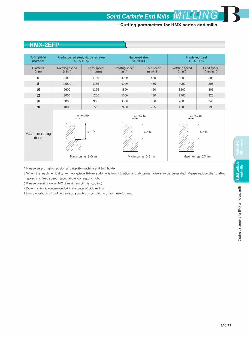
Workpiece material
Pre-hardened steel, Hardened steel40~50HRC
Hardened steel50~60HRC
Hardened steel60~68HRC
Diameter(mm)
Rotating speed(min-1)
Feed speed(mm/min)
Rotating speed(min-1)
Feed speed(mm/min)
Rotating speed(min-1)
Feed speed(mm/min)
6 16000 1155 8000 460 5300 305
8 12000 1155 6000 460 4000 305
10 9600 1155 4800 460 3200 305
12 8000 1200 4000 480 2700 325
16 6000 900 3000 360 2000 240
20 4800 720 2400 285 1600 195
Maximum cutting depth
1.Please select high-precision and rigidity machine and tool holder.
2.When the machine rigidity and workpiece fixture stability is low, vibration and abnormal noise may be generated. Please reduce the rotating
speed and feed speed stated above correspondingly.
3.Please use air blow or MQL( minimum oil mist cooling).
4.Down milling is recommended in the case of side milling.
5.Make overhang of tool as short as possible in conditions of non-interference.
Maximum ae=1.0mm Maximum ae=0.5mm Maximum ae=0.3mm
ae=0.03D
ap=1D
ae=0.02D
ap=1D
ae=0.05D
ap=1D
HMX-2EFP
Cutt
ing
para
met
ers f
or H
MX
serie
s end
mill
s
B
B 411
Solid Carbide End Mills MILLINGMILLING
Inde
xabl
e m
illin
g to
ols
Solid
car
bide
en
d m
ills
Cutting parameters for HMX series end mills
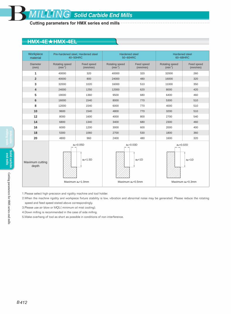
Workpiece material
Pre-hardened steel, Hardened steel40~50HRC
Hardened steel50~60HRC
Hardened steel60~68HRC
Diameter(mm)
Rotating speed(min-1)
Feed speed(mm/min)
Rotating speed(min-1)
Feed speed(mm/min)
Rotating speed(min-1)
Feed speed(mm/min)
1 40000 320 40000 320 32000 260
2 40000 800 24000 480 16000 320
3 32000 1020 16000 510 11000 350
4 24000 1250 12000 620 8000 420
5 19000 1360 9500 680 6400 460
6 16000 1540 8000 770 5300 510
8 12000 1540 6000 770 4000 510
10 9600 1540 4800 770 3200 510
12 8000 1600 4000 800 2700 540
14 6800 1340 3400 680 2300 460
16 6000 1200 3000 600 2000 400
18 5300 1060 2700 530 1800 360
20 4800 960 2400 480 1600 320
Maximum cutting depth
1.Please select high-precision and rigidity machine and tool holder.
2.When the machine rigidity and workpiece fixture stability is low, vibration and abnormal noise may be generated. Please reduce the rotating
speed and feed speed stated above correspondingly.
3.Please use air blow or MQL( minimum oil mist cooling).
4.Down milling is recommended in the case of side milling.
5.Make overhang of tool as short as possible in conditions of non-interference.
Maximum ae=1.0mm Maximum ae=0.5mm Maximum ae=0.3mm
ae=0.03D
ap=1D
ae=0.05D
ap=1.5D
ae=0.02D
ap=1D
HMX-4E★HMX-4EL
Cutting parameters for HM
X series end mills
B
B 412
Solid Carbide End MillsMILLINGMILLING
Indexable m
illing toolsSolid carbide
end mills
Cutting parameters for HMX series end mills
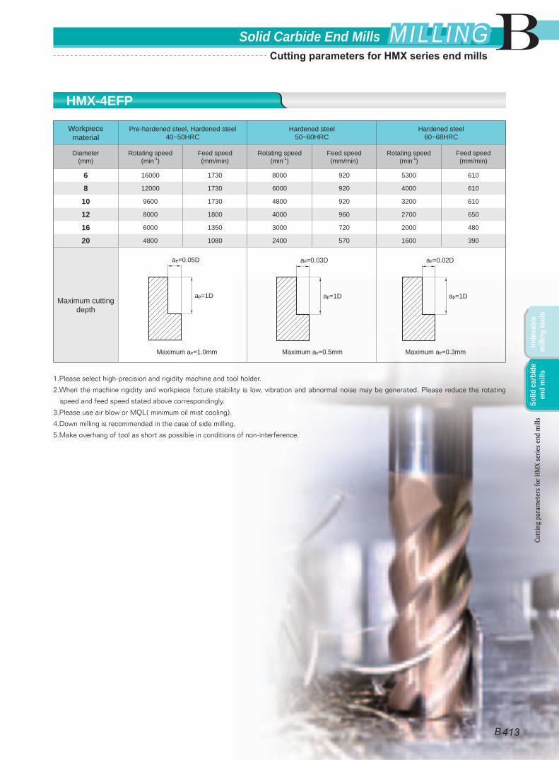
Workpiece material
Pre-hardened steel, Hardened steel40~50HRC
Hardened steel50~60HRC
Hardened steel60~68HRC
Diameter(mm)
Rotating speed(min-1)
Feed speed(mm/min)
Rotating speed(min-1)
Feed speed(mm/min)
Rotating speed(min-1)
Feed speed(mm/min)
6 16000 1730 8000 920 5300 610
8 12000 1730 6000 920 4000 610
10 9600 1730 4800 920 3200 610
12 8000 1800 4000 960 2700 650
16 6000 1350 3000 720 2000 480
20 4800 1080 2400 570 1600 390
Maximum cutting depth
1.Please select high-precision and rigidity machine and tool holder.
2.When the machine rigidity and workpiece fixture stability is low, vibration and abnormal noise may be generated. Please reduce the rotating
speed and feed speed stated above correspondingly.
3.Please use air blow or MQL( minimum oil mist cooling).
4.Down milling is recommended in the case of side milling.
5.Make overhang of tool as short as possible in conditions of non-interference.
Maximum ae=1.0mm Maximum ae=0.5mm Maximum ae=0.3mm
ae=0.03D
ap=1D
ae=0.02D
ap=1D
ae=0.05D
ap=1D
HMX-4EFP
Cutt
ing
para
met
ers f
or H
MX
serie
s end
mill
s
B
B 413
Solid Carbide End Mills MILLINGMILLING
Inde
xabl
e m
illin
g to
ols
Solid
car
bide
en
d m
ills
Cutting parameters for HMX series end mills

Workpiece material
Pre-hardened steel, Hardened steel40~50HRC
Hardened steel50~60HRC
Hardened steel60~68HRC
Cutting speed 300m/min 150m/min 100m/min
Diameter(mm)
Rotating speed(min-1)
Feed speed(mm/min)
Rotating speed(min-1)
Feed speed(mm/min)
Rotating speed(min-1)
Feed speed(mm/min)
6 16000 1850 8000 925 5300 610
8 12000 1850 6000 925 4000 610
10 9600 1850 4800 925 3200 610
12 8000 1920 4000 960 2700 650
14 6800 1600 3400 815 2300 550
16 6000 1440 3000 720 2000 480
18 5300 1270 2700 635 1800 430
20 4800 1150 2400 575 1600 385
Maximum cutting depth
1.Please select high-precision and rigidity machine and tool holder.
2.When the machine rigidity and workpiece fixture stability is low, vibration and abnormal noise may be generated. Please reduce the rotating
speed and feed speed stated above correspondingly.
3.Please use air blow or MQL( minimum oil mist cooling).
4.Down milling is recommended in the case of side milling.
5.Make overhang of tool as short as possible in conditions of non-interference.
Maximum ae=1.0mm Maximum ae=0.5mm Maximum ae=0.3mm
ae=0.03D
ap=1.5D
ae=0.05D
ap=1.5D
ae=0.02D
ap=1.5D
HMX-6E
Cutting parameters for HM
X series end mills
B
B 414
Solid Carbide End MillsMILLINGMILLING
Indexable m
illing toolsSolid carbide
end mills
Cutting parameters for HMX series end mills
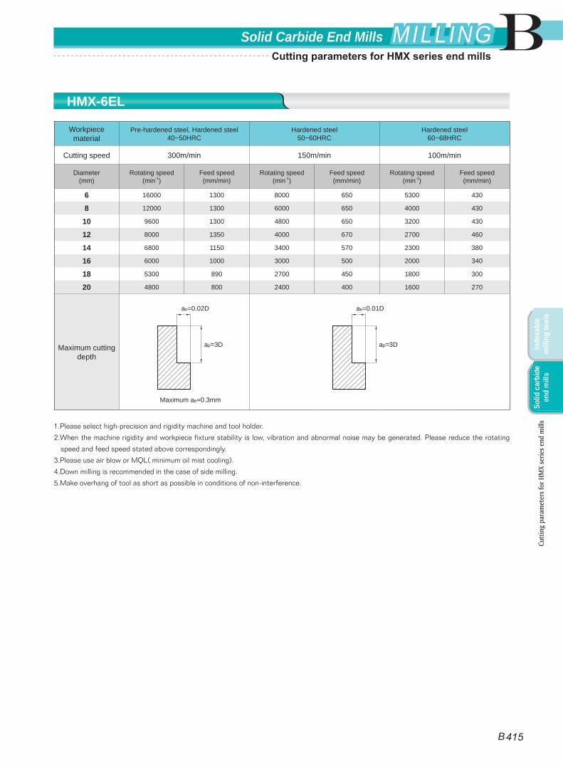
Workpiece material
Pre-hardened steel, Hardened steel40~50HRC
Hardened steel50~60HRC
Hardened steel60~68HRC
Cutting speed 300m/min 150m/min 100m/min
Diameter(mm)
Rotating speed(min-1)
Feed speed(mm/min)
Rotating speed(min-1)
Feed speed(mm/min)
Rotating speed(min-1)
Feed speed(mm/min)
6 16000 1300 8000 650 5300 430
8 12000 1300 6000 650 4000 430
10 9600 1300 4800 650 3200 430
12 8000 1350 4000 670 2700 460
14 6800 1150 3400 570 2300 380
16 6000 1000 3000 500 2000 340
18 5300 890 2700 450 1800 300
20 4800 800 2400 400 1600 270
Maximum cutting depth
1.Please select high-precision and rigidity machine and tool holder.
2.When the machine rigidity and workpiece fixture stability is low, vibration and abnormal noise may be generated. Please reduce the rotating
speed and feed speed stated above correspondingly.
3.Please use air blow or MQL( minimum oil mist cooling).
4.Down milling is recommended in the case of side milling.
5.Make overhang of tool as short as possible in conditions of non-interference.
Maximum ae=0.3mm
ae=0.02D
ap=3D
ae=0.01D
ap=3D
HMX-6EL
Cutt
ing
para
met
ers f
or H
MX
serie
s end
mill
s
B
B 415
Solid Carbide End Mills MILLINGMILLING
Inde
xabl
e m
illin
g to
ols
Solid
car
bide
en
d m
ills
Cutting parameters for HMX series end mills
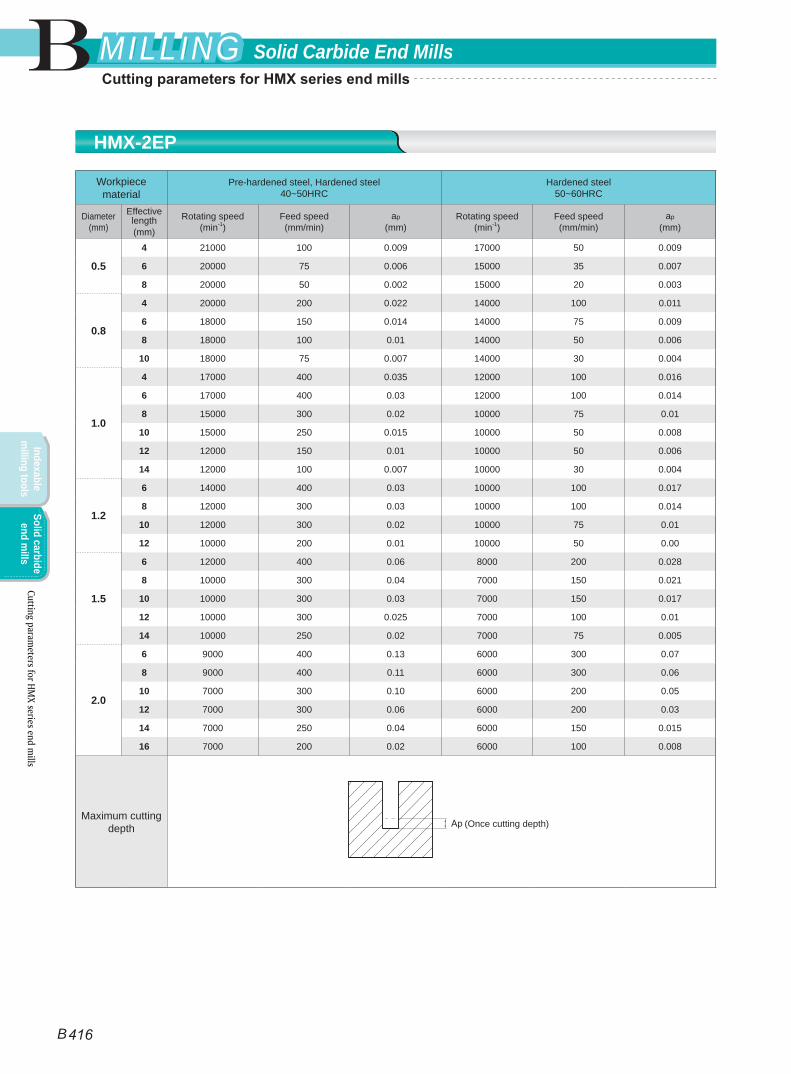
Workpiece material
Pre-hardened steel, Hardened steel40~50HRC
Hardened steel50~60HRC
Diameter(mm)
Effective length(mm)
Rotating speed(min-1)
Feed speed(mm/min)
ap
(mm)Rotating speed
(min-1)Feed speed(mm/min)
ap
(mm)
0.5
4 21000 100 0.009 17000 50 0.009
6 20000 75 0.006 15000 35 0.007
8 20000 50 0.002 15000 20 0.003
0.8
4 20000 200 0.022 14000 100 0.011
6 18000 150 0.014 14000 75 0.009
8 18000 100 0.01 14000 50 0.006
10 18000 75 0.007 14000 30 0.004
1.0
4 17000 400 0.035 12000 100 0.016
6 17000 400 0.03 12000 100 0.014
8 15000 300 0.02 10000 75 0.01
10 15000 250 0.015 10000 50 0.008
12 12000 150 0.01 10000 50 0.006
14 12000 100 0.007 10000 30 0.004
1.2
6 14000 400 0.03 10000 100 0.017
8 12000 300 0.03 10000 100 0.014
10 12000 300 0.02 10000 75 0.01
12 10000 200 0.01 10000 50 0.00
1.5
6 12000 400 0.06 8000 200 0.028
8 10000 300 0.04 7000 150 0.021
10 10000 300 0.03 7000 150 0.017
12 10000 300 0.025 7000 100 0.01
14 10000 250 0.02 7000 75 0.005
2.0
6 9000 400 0.13 6000 300 0.07
8 9000 400 0.11 6000 300 0.06
10 7000 300 0.10 6000 200 0.05
12 7000 300 0.06 6000 200 0.03
14 7000 250 0.04 6000 150 0.015
16 7000 200 0.02 6000 100 0.008
Maximum cutting depth (Once cutting depth)
HMX-2EP
Cutting parameters for HM
X series end mills
B
B 416
Solid Carbide End MillsMILLINGMILLING
Indexable m
illing toolsSolid carbide
end mills
Cutting parameters for HMX series end mills
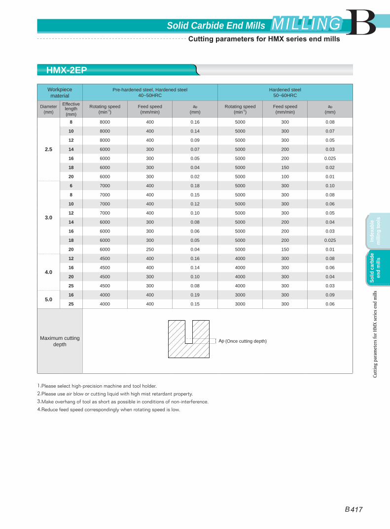
Workpiece material
Pre-hardened steel, Hardened steel40~50HRC
Hardened steel50~60HRC
Diameter(mm)
Effective length(mm)
Rotating speed(min-1)
Feed speed(mm/min)
ap
(mm)Rotating speed
(min-1)Feed speed(mm/min)
ap
(mm)
2.5
8 8000 400 0.16 5000 300 0.08
10 8000 400 0.14 5000 300 0.07
12 8000 400 0.09 5000 300 0.05
14 6000 300 0.07 5000 200 0.03
16 6000 300 0.05 5000 200 0.025
18 6000 300 0.04 5000 150 0.02
20 6000 300 0.02 5000 100 0.01
3.0
6 7000 400 0.18 5000 300 0.10
8 7000 400 0.15 5000 300 0.08
10 7000 400 0.12 5000 300 0.06
12 7000 400 0.10 5000 300 0.05
14 6000 300 0.08 5000 200 0.04
16 6000 300 0.06 5000 200 0.03
18 6000 300 0.05 5000 200 0.025
20 6000 250 0.04 5000 150 0.01
4.0
12 4500 400 0.16 4000 300 0.08
16 4500 400 0.14 4000 300 0.06
20 4500 300 0.10 4000 300 0.04
25 4500 300 0.08 4000 300 0.03
5.016 4000 400 0.19 3000 300 0.09
25 4000 400 0.15 3000 300 0.06
Maximum cutting depth
1.Please select high-precision machine and tool holder.
2.Please use air blow or cutting liquid with high mist retardant property.
3.Make overhang of tool as short as possible in conditions of non-interference.
4.Reduce feed speed correspondingly when rotating speed is low.
(Once cutting depth)
HMX-2EP
Cutt
ing
para
met
ers f
or H
MX
serie
s end
mill
s
B
B 417
Solid Carbide End Mills MILLINGMILLING
Inde
xabl
e m
illin
g to
ols
Solid
car
bide
en
d m
ills
Cutting parameters for HMX series end mills
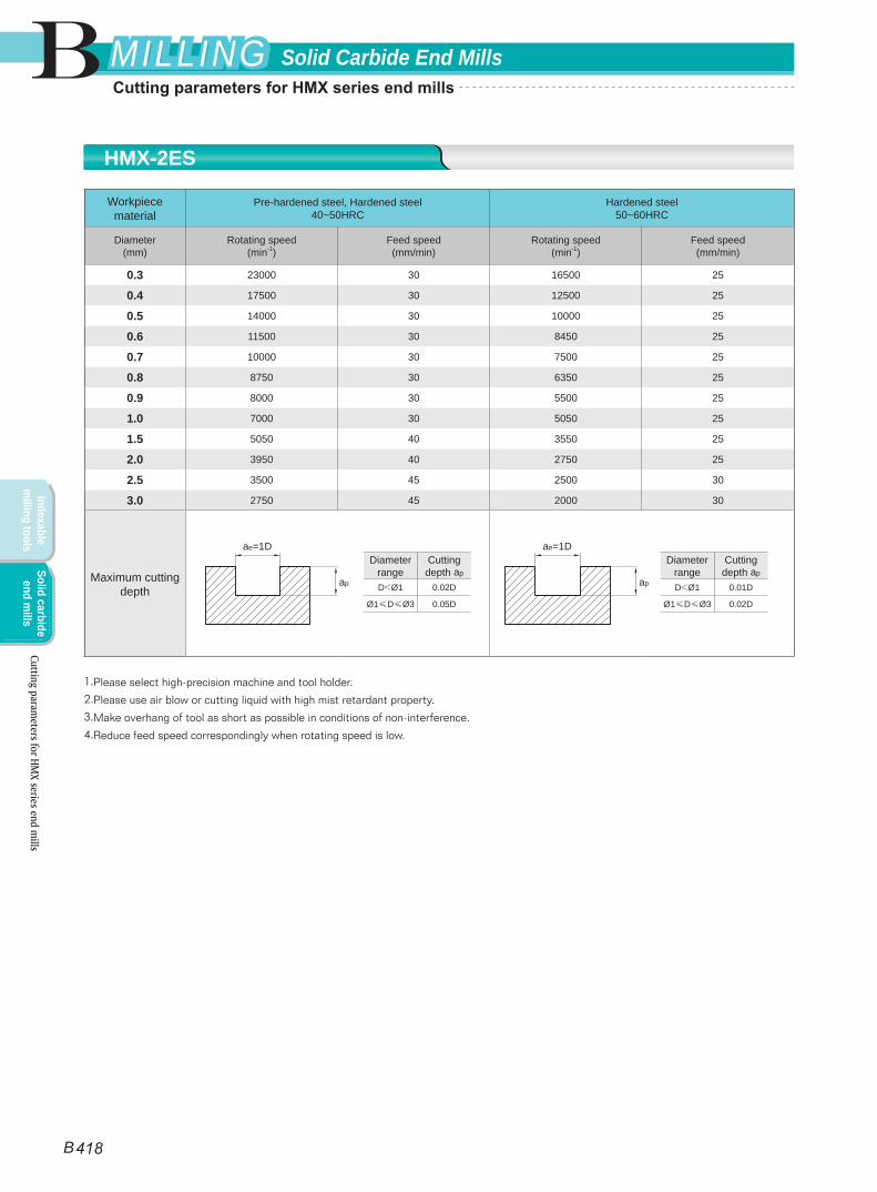
Workpiece material
Pre-hardened steel, Hardened steel40~50HRC
Hardened steel50~60HRC
Diameter(mm)
Rotating speed(min-1)
Feed speed(mm/min)
Rotating speed(min-1)
Feed speed(mm/min)
0.3 23000 30 16500 25
0.4 17500 30 12500 25
0.5 14000 30 10000 25
0.6 11500 30 8450 25
0.7 10000 30 7500 25
0.8 8750 30 6350 25
0.9 8000 30 5500 25
1.0 7000 30 5050 25
1.5 5050 40 3550 25
2.0 3950 40 2750 25
2.5 3500 45 2500 30
3.0 2750 45 2000 30
Maximum cutting depth
1.Please select high-precision machine and tool holder.
2.Please use air blow or cutting liquid with high mist retardant property.
3.Make overhang of tool as short as possible in conditions of non-interference.
4.Reduce feed speed correspondingly when rotating speed is low.
Diameter range
Cutting depth ap
D<Ø1 0.02D
Ø1≤D≤Ø3 0.05D
Diameter range
Cutting depth ap
D<Ø1 0.01D
Ø1≤D≤Ø3 0.02D
ae=1D
ap
ae=1D
ap
HMX-2ES
Cutting parameters for HM
X series end mills
B
B 418
Solid Carbide End MillsMILLINGMILLING
Indexable m
illing toolsSolid carbide
end mills
Cutting parameters for HMX series end mills
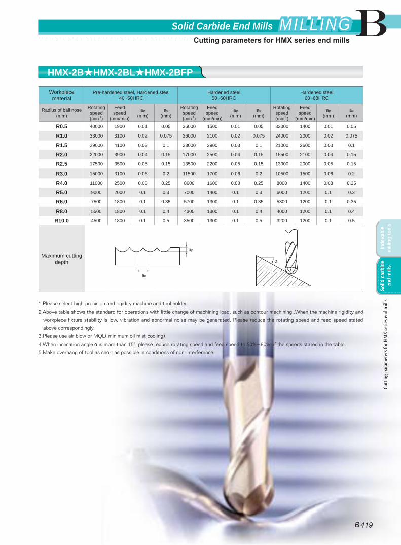
Workpiece material
Pre-hardened steel, Hardened steel40~50HRC
Hardened steel50~60HRC
Hardened steel60~68HRC
Radius of ball nose(mm)
Rotating speed(min-1)
Feed speed
(mm/min)
ap
(mm)ae
(mm)
Rotating speed(min-1)
Feed speed
(mm/min)
ap
(mm)ae
(mm)
Rotating speed(min-1)
Feed speed
(mm/min)
ap
(mm)ae
(mm)
R0.5 40000 1900 0.01 0.05 36000 1500 0.01 0.05 32000 1400 0.01 0.05
R1.0 33000 3100 0.02 0.075 26000 2100 0.02 0.075 24000 2000 0.02 0.075
R1.5 29000 4100 0.03 0.1 23000 2900 0.03 0.1 21000 2600 0.03 0.1
R2.0 22000 3900 0.04 0.15 17000 2500 0.04 0.15 15500 2100 0.04 0.15
R2.5 17500 3500 0.05 0.15 13500 2200 0.05 0.15 13000 2000 0.05 0.15
R3.0 15000 3100 0.06 0.2 11500 1700 0.06 0.2 10500 1500 0.06 0.2
R4.0 11000 2500 0.08 0.25 8600 1600 0.08 0.25 8000 1400 0.08 0.25
R5.0 9000 2000 0.1 0.3 7000 1400 0.1 0.3 6000 1200 0.1 0.3
R6.0 7500 1800 0.1 0.35 5700 1300 0.1 0.35 5300 1200 0.1 0.35
R8.0 5500 1800 0.1 0.4 4300 1300 0.1 0.4 4000 1200 0.1 0.4
R10.0 4500 1800 0.1 0.5 3500 1300 0.1 0.5 3200 1200 0.1 0.5
Maximum cutting depth
1.Please select high-precision and rigidity machine and tool holder.
2.Above table shows the standard for operations with little change of machining load, such as contour machining .When the machine rigidity and
workpiece fixture stability is low, vibration and abnormal noise may be generated. Please reduce the rotating speed and feed speed stated
above correspondingly.
3.Please use air blow or MQL( minimum oil mist cooling).
4.When inclination angle α is more than 15°, please reduce rotating speed and feed speed to 50%~80% of the speeds stated in the table.
5.Make overhang of tool as short as possible in conditions of non-interference.
ae
ap
HMX-2B★HMX-2BL★HMX-2BFP
Cutt
ing
para
met
ers f
or H
MX
serie
s end
mill
s
B
B 419
Solid Carbide End Mills MILLINGMILLING
Inde
xabl
e m
illin
g to
ols
Solid
car
bide
en
d m
ills
Cutting parameters for HMX series end mills
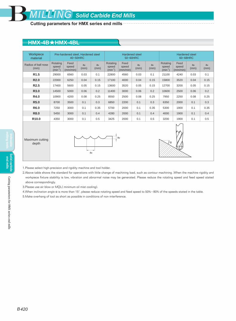
Workpiece material
Pre-hardened steel, Hardened steel40~50HRC
Hardened steel50~60HRC
Hardened steel60~68HRC
Radius of ball nose(mm)
Rotating speed(min-1)
Feed speed
(mm/min)
ap
(mm)ae
(mm)
Rotating speed(min-1)
Feed speed
(mm/min)
ap
(mm)ae
(mm)
Rotating speed(min-1)
Feed speed
(mm/min)
ap
(mm)ae
(mm)
R1.5 29000 6560 0.03 0.1 22800 4560 0.03 0.1 21100 4240 0.03 0.1
R2.0 22000 6250 0.04 0.15 17100 4000 0.04 0.15 15800 3520 0.04 0.15
R2.5 17400 5600 0.05 0.15 13600 3520 0.05 0.15 12700 3200 0.05 0.15
R3.0 14500 5000 0.06 0.2 11400 3000 0.06 0.2 10600 2500 0.06 0.2
R4.0 10900 4200 0.08 0.25 8550 2500 0.08 0.25 7950 2250 0.08 0.25
R5.0 8700 3500 0.1 0.3 6850 2200 0.1 0.3 6350 2000 0.1 0.3
R6.0 7250 3000 0.1 0.35 5700 2000 0.1 0.35 5300 1900 0.1 0.35
R8.0 5450 3000 0.1 0.4 4280 2000 0.1 0.4 4000 1900 0.1 0.4
R10.0 4350 3000 0.1 0.5 3425 2000 0.1 0.5 3200 1900 0.1 0.5
Maximum cutting depth
1.Please select high-precision and rigidity machine and tool holder.
2.Above table shows the standard for operations with little change of machining load, such as contour machining .When the machine rigidity and
workpiece fixture stability is low, vibration and abnormal noise may be generated. Please reduce the rotating speed and feed speed stated
above correspondingly.
3.Please use air blow or MQL( minimum oil mist cooling).
4.When inclination angle α is more than 15°, please reduce rotating speed and feed speed to 50%~80% of the speeds stated in the table.
5.Make overhang of tool as short as possible in conditions of non-interference.
ae
ap
HMX-4B★HMX-4BL
Cutting parameters for HM
X series end mills
B
B 420
Solid Carbide End MillsMILLINGMILLING
Indexable m
illing toolsSolid carbide
end mills
Cutting parameters for HMX series end mills
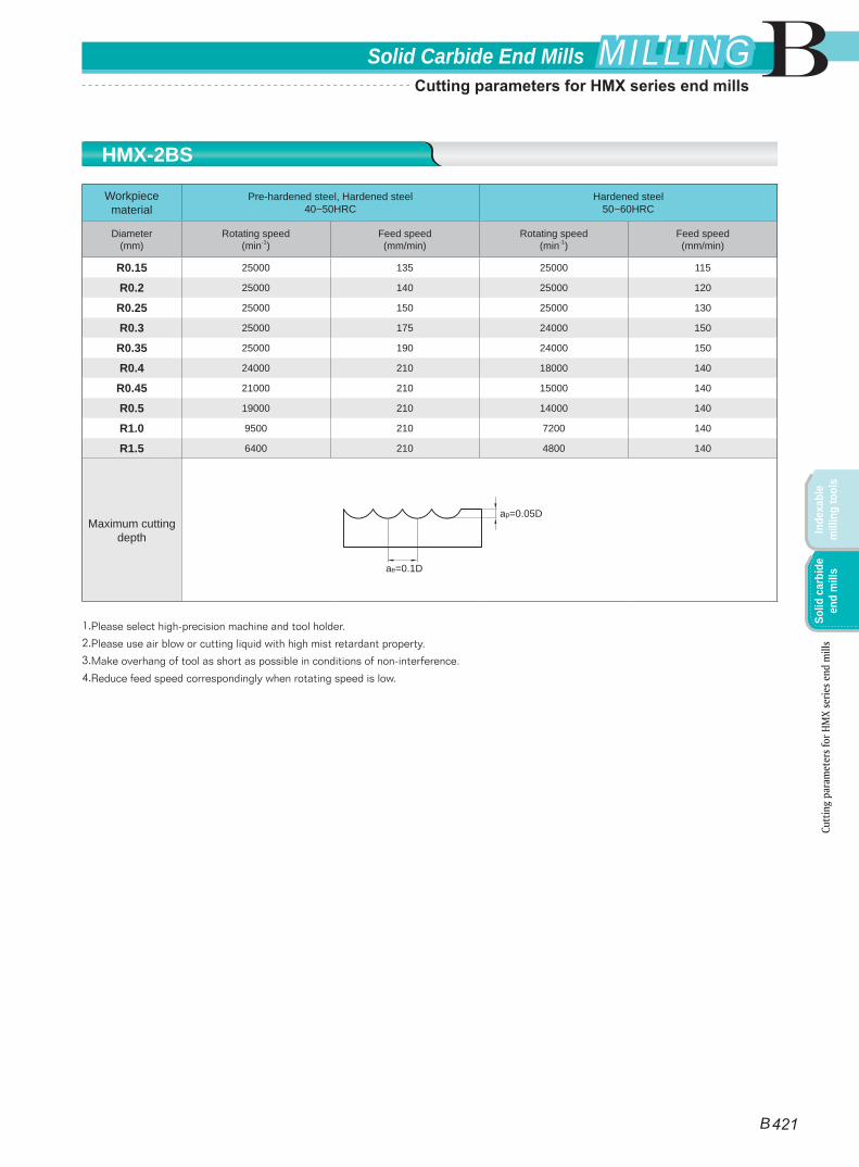
Workpiece material
Pre-hardened steel, Hardened steel40~50HRC
Hardened steel50~60HRC
Diameter(mm)
Rotating speed(min-1)
Feed speed(mm/min)
Rotating speed(min-1)
Feed speed(mm/min)
R0.15 25000 135 25000 115
R0.2 25000 140 25000 120
R0.25 25000 150 25000 130
R0.3 25000 175 24000 150
R0.35 25000 190 24000 150
R0.4 24000 210 18000 140
R0.45 21000 210 15000 140
R0.5 19000 210 14000 140
R1.0 9500 210 7200 140
R1.5 6400 210 4800 140
Maximum cutting depth
1.Please select high-precision machine and tool holder.
2.Please use air blow or cutting liquid with high mist retardant property.
3.Make overhang of tool as short as possible in conditions of non-interference.
4.Reduce feed speed correspondingly when rotating speed is low.
ae=0.1D
ap=0.05D
HMX-2BS
Cutt
ing
para
met
ers f
or H
MX
serie
s end
mill
s
B
B 421
Solid Carbide End Mills MILLINGMILLING
Inde
xabl
e m
illin
g to
ols
Solid
car
bide
en
d m
ills
Cutting parameters for HMX series end mills
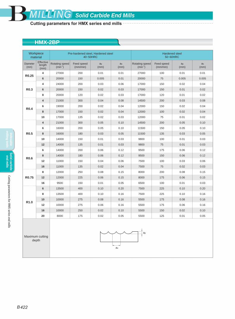
Workpiece material
Pre-hardened steel, Hardened steel40~50HRC
Hardened steel50~60HRC
Diameter(mm)
Effective length(mm)
Rotating speed(min-1)
Feed speed(mm/min)
ap
(mm)ae
(mm)Rotating speed
(min-1)Feed speed(mm/min)
ap
(mm)ae
(mm)
R0.254 27000 200 0.01 0.01 27000 100 0.01 0.01
6 20000 150 0.005 0.01 20000 75 0.005 0.005
R0.3
4 24000 200 0.03 0.06 17000 150 0.02 0.04
6 20000 150 0.02 0.03 17000 150 0.01 0.02
8 20000 120 0.02 0.03 17000 120 0.01 0.02
R0.4
4 21000 300 0.04 0.08 14500 200 0.03 0.08
6 19000 200 0.02 0.04 12000 150 0.02 0.04
8 17000 150 0.02 0.04 12000 100 0.02 0.04
10 17000 135 0.02 0.03 12000 75 0.01 0.02
R0.5
4 21000 300 0.05 0.10 14500 200 0.05 0.10
6 16000 200 0.05 0.10 11500 150 0.05 0.10
8 16000 180 0.03 0.05 11500 135 0.03 0.05
10 14000 150 0.01 0.03 9800 100 0.01 0.03
12 14000 135 0.01 0.03 9800 75 0.01 0.03
R0.6
6 14000 200 0.06 0.12 9500 175 0.06 0.12
8 14000 180 0.06 0.12 9500 150 0.06 0.12
12 11000 150 0.04 0.06 7500 100 0.03 0.06
16 11000 135 0.02 0.04 7500 75 0.02 0.03
R0.75
8 12000 250 0.08 0.15 8000 200 0.08 0.15
12 12000 225 0.06 0.15 8000 175 0.06 0.15
16 9500 150 0.01 0.05 6500 100 0.01 0.03
R1.0
6 13500 400 0.10 0.20 7500 225 0.10 0.20
8 13500 400 0.10 0.16 7500 225 0.10 0.16
10 10000 275 0.08 0.16 5500 175 0.08 0.16
12 10000 275 0.06 0.16 5500 175 0.06 0.16
16 10000 250 0.02 0.10 5500 150 0.02 0.10
20 8000 175 0.02 0.05 5500 125 0.01 0.05
Maximum cutting depth
ae
ap
HMX-2BP
Cutting parameters for HM
X series end mills
B
B 422
Solid Carbide End MillsMILLINGMILLING
Indexable m
illing toolsSolid carbide
end mills
Cutting parameters for HMX series end mills
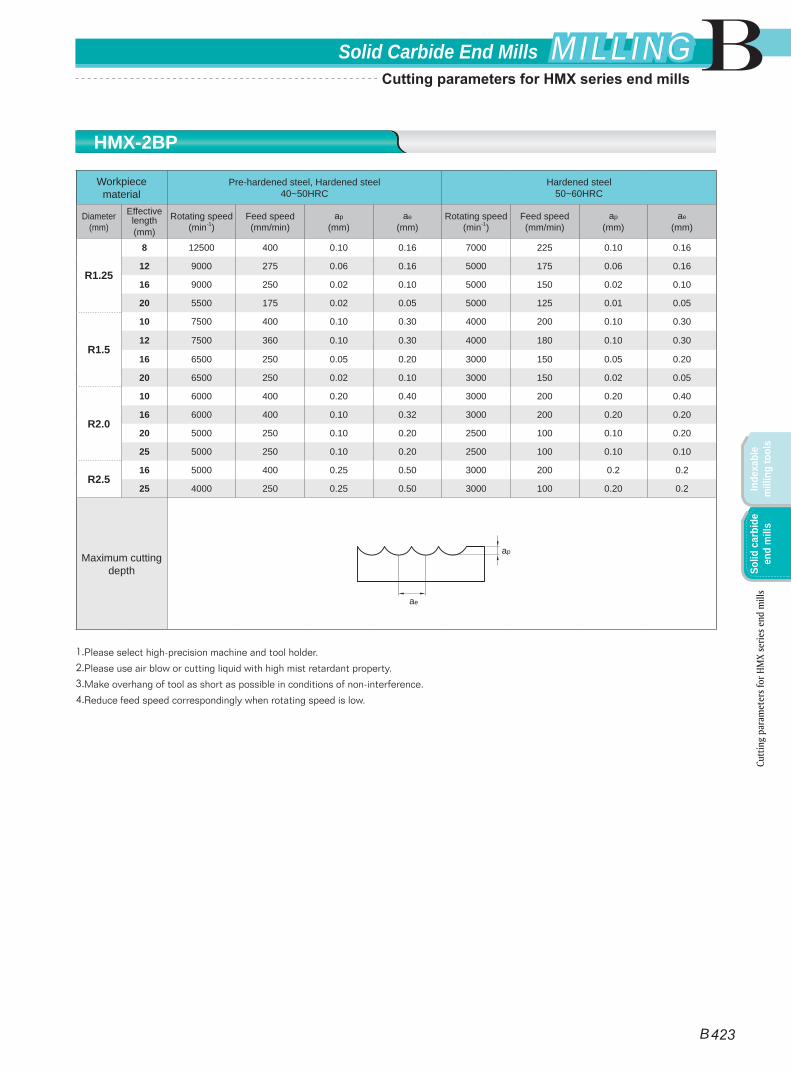
Workpiece material
Pre-hardened steel, Hardened steel40~50HRC
Hardened steel50~60HRC
Diameter(mm)
Effective length(mm)
Rotating speed(min-1)
Feed speed(mm/min)
ap
(mm)ae
(mm)Rotating speed
(min-1)Feed speed(mm/min)
ap
(mm)ae
(mm)
R1.25
8 12500 400 0.10 0.16 7000 225 0.10 0.16
12 9000 275 0.06 0.16 5000 175 0.06 0.16
16 9000 250 0.02 0.10 5000 150 0.02 0.10
20 5500 175 0.02 0.05 5000 125 0.01 0.05
R1.5
10 7500 400 0.10 0.30 4000 200 0.10 0.30
12 7500 360 0.10 0.30 4000 180 0.10 0.30
16 6500 250 0.05 0.20 3000 150 0.05 0.20
20 6500 250 0.02 0.10 3000 150 0.02 0.05
R2.0
10 6000 400 0.20 0.40 3000 200 0.20 0.40
16 6000 400 0.10 0.32 3000 200 0.20 0.20
20 5000 250 0.10 0.20 2500 100 0.10 0.20
25 5000 250 0.10 0.20 2500 100 0.10 0.10
R2.516 5000 400 0.25 0.50 3000 200 0.2 0.2
25 4000 250 0.25 0.50 3000 100 0.20 0.2
Maximum cutting depth
1.Please select high-precision machine and tool holder.
2.Please use air blow or cutting liquid with high mist retardant property.
3.Make overhang of tool as short as possible in conditions of non-interference.
4.Reduce feed speed correspondingly when rotating speed is low.
ae
ap
HMX-2BP
Cutt
ing
para
met
ers f
or H
MX
serie
s end
mill
s
B
B 423
Solid Carbide End Mills MILLINGMILLING
Inde
xabl
e m
illin
g to
ols
Solid
car
bide
en
d m
ills
Cutting parameters for HMX series end mills
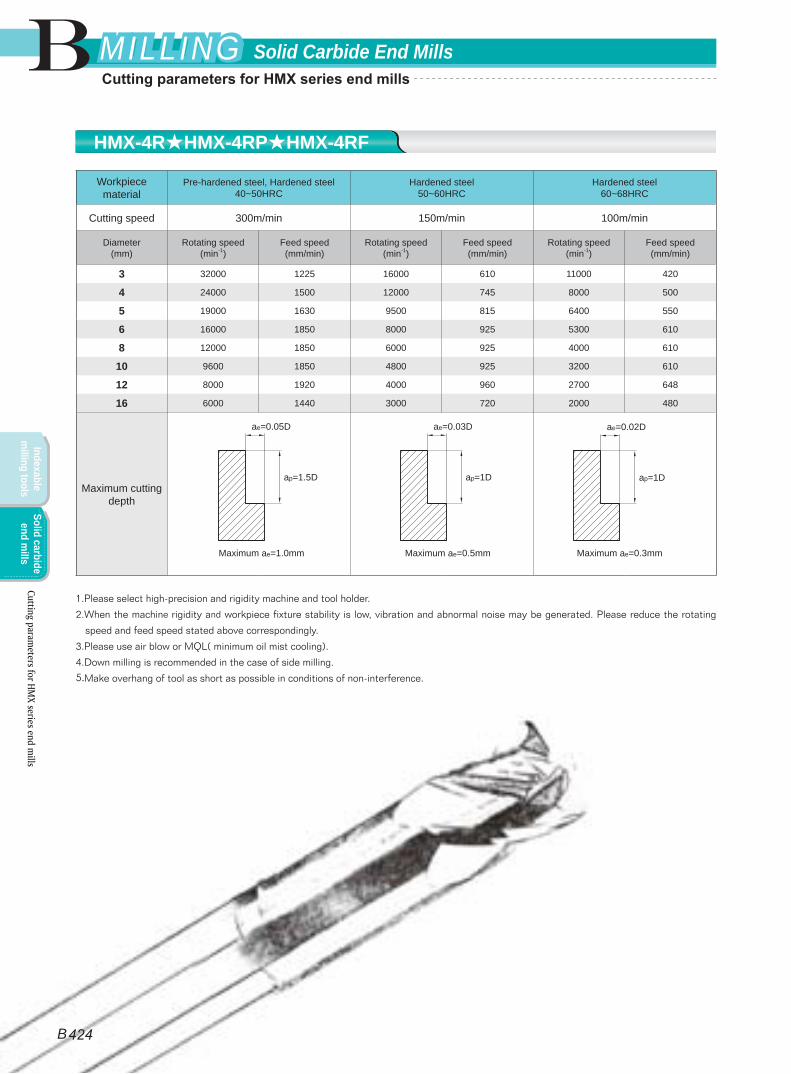
Workpiece material
Pre-hardened steel, Hardened steel40~50HRC
Hardened steel50~60HRC
Hardened steel60~68HRC
Cutting speed 300m/min 150m/min 100m/min
Diameter(mm)
Rotating speed(min-1)
Feed speed(mm/min)
Rotating speed(min-1)
Feed speed(mm/min)
Rotating speed(min-1)
Feed speed(mm/min)
3 32000 1225 16000 610 11000 420
4 24000 1500 12000 745 8000 500
5 19000 1630 9500 815 6400 550
6 16000 1850 8000 925 5300 610
8 12000 1850 6000 925 4000 610
10 9600 1850 4800 925 3200 610
12 8000 1920 4000 960 2700 648
16 6000 1440 3000 720 2000 480
Maximum cutting depth
1.Please select high-precision and rigidity machine and tool holder.
2.When the machine rigidity and workpiece fixture stability is low, vibration and abnormal noise may be generated. Please reduce the rotating
speed and feed speed stated above correspondingly.
3.Please use air blow or MQL( minimum oil mist cooling).
4.Down milling is recommended in the case of side milling.
5.Make overhang of tool as short as possible in conditions of non-interference.
Maximum ae=1.0mm Maximum ae=0.5mm Maximum ae=0.3mm
ae=0.03D
ap=1D
ae=0.05D
ap=1.5D
ae=0.02D
ap=1D
HMX-4R★HMX-4RP★HMX-4RF
Cutting parameters for HM
X series end mills
B
B 424
Solid Carbide End MillsMILLINGMILLING
Indexable m
illing toolsSolid carbide
end mills
Cutting parameters for HMX series end mills
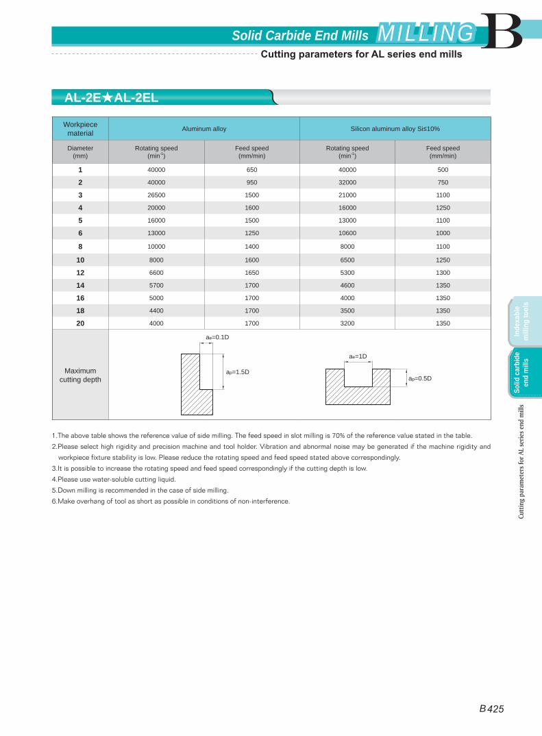
Workpiece material Aluminum alloy Silicon aluminum alloy Si≤10%
Diameter(mm)
Rotating speed(min-1)
Feed speed(mm/min)
Rotating speed(min-1)
Feed speed(mm/min)
1 40000 650 40000 500
2 40000 950 32000 750
3 26500 1500 21000 1100
4 20000 1600 16000 1250
5 16000 1500 13000 1100
6 13000 1250 10600 1000
8 10000 1400 8000 1100
10 8000 1600 6500 1250
12 6600 1650 5300 1300
14 5700 1700 4600 1350
16 5000 1700 4000 1350
18 4400 1700 3500 1350
20 4000 1700 3200 1350
Maximum cutting depth
1.The above table shows the reference value of side milling. The feed speed in slot milling is 70% of the reference value stated in the table.
2.Please select high rigidity and precision machine and tool holder. Vibration and abnormal noise may be generated if the machine rigidity and
workpiece fixture stability is low. Please reduce the rotating speed and feed speed stated above correspondingly.
3.It is possible to increase the rotating speed and feed speed correspondingly if the cutting depth is low.
4.Please use water-soluble cutting liquid.
5.Down milling is recommended in the case of side milling.
6.Make overhang of tool as short as possible in conditions of non-interference.
ae=0.1D
ap=1.5D
ae=1D
ap=0.5D
AL-2E★AL-2EL
Cutt
ing
para
met
ers f
or A
L se
ries e
nd m
ills
B 425
BSolid Carbide End Mills MILLINGMILLING
Inde
xabl
e m
illin
g to
ols
Solid
car
bide
en
d m
ills
Cutting parameters for AL series end mills
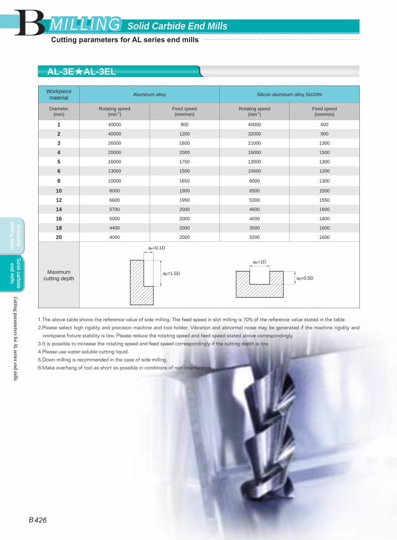
Workpiece material Aluminum alloy Silicon aluminum alloy Si≤10%
Diameter(mm)
Rotating speed(min-1)
Feed speed(mm/min)
Rotating speed(min-1)
Feed speed(mm/min)
1 40000 800 40000 600
2 40000 1200 32000 900
3 26500 1800 21000 1300
4 20000 2000 16000 1500
5 16000 1750 13000 1300
6 13000 1500 10600 1200
8 10000 1650 8000 1300
10 8000 1900 6500 1500
12 6600 1950 5300 1550
14 5700 2000 4600 1600
16 5000 2000 4000 1600
18 4400 2000 3500 1600
20 4000 2000 3200 1600
Maximum cutting depth
1.The above table shows the reference value of side milling. The feed speed in slot milling is 70% of the reference value stated in the table.
2.Please select high rigidity and precision machine and tool holder. Vibration and abnormal noise may be generated if the machine rigidity and
workpiece fixture stability is low. Please reduce the rotating speed and feed speed stated above correspondingly.
3.It is possible to increase the rotating speed and feed speed correspondingly if the cutting depth is low.
4.Please use water-soluble cutting liquid.
5.Down milling is recommended in the case of side milling.
6.Make overhang of tool as short as possible in conditions of non-interference.
ae=0.1D
ap=1.5D
ae=1D
ap=0.5D
AL-3E★AL-3EL
Cutting parameters for AL series end m
ills
B 426
B Solid Carbide End MillsMILLINGMILLING
Indexable m
illing toolsSolid carbide
end mills
Cutting parameters for AL series end mills
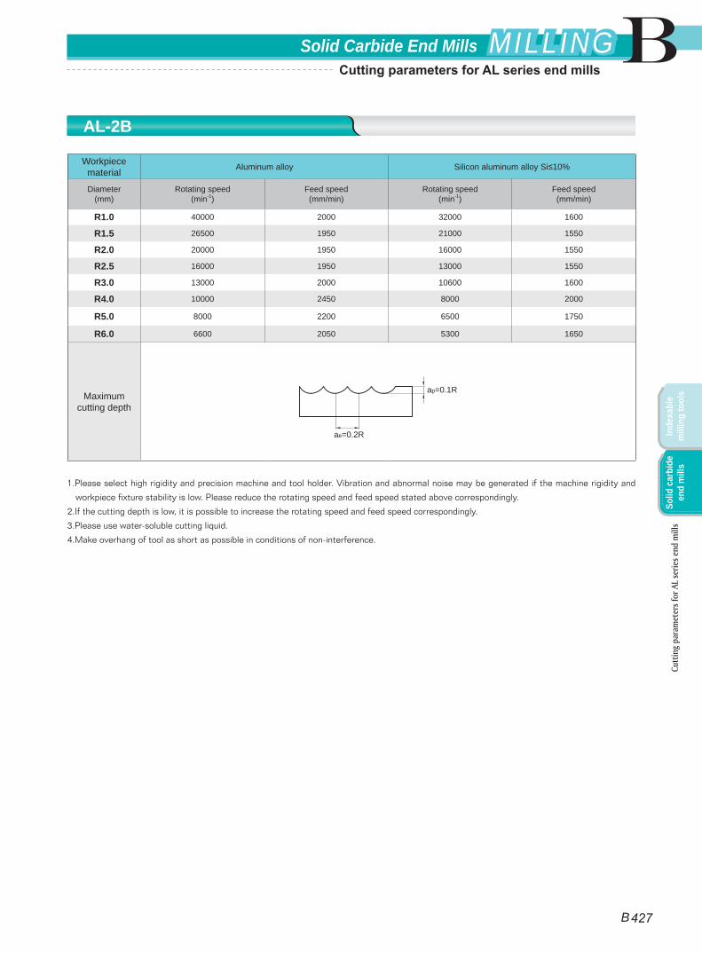
Workpiece material Aluminum alloy Silicon aluminum alloy Si≤10%
Diameter(mm)
Rotating speed(min-1)
Feed speed(mm/min)
Rotating speed(min-1)
Feed speed(mm/min)
R1.0 40000 2000 32000 1600
R1.5 26500 1950 21000 1550
R2.0 20000 1950 16000 1550
R2.5 16000 1950 13000 1550
R3.0 13000 2000 10600 1600
R4.0 10000 2450 8000 2000
R5.0 8000 2200 6500 1750
R6.0 6600 2050 5300 1650
Maximum cutting depth
1.Please select high rigidity and precision machine and tool holder. Vibration and abnormal noise may be generated if the machine rigidity and
workpiece fixture stability is low. Please reduce the rotating speed and feed speed stated above correspondingly.
2.If the cutting depth is low, it is possible to increase the rotating speed and feed speed correspondingly.
3.Please use water-soluble cutting liquid.
4.Make overhang of tool as short as possible in conditions of non-interference.
ae=0.2R
ap=0.1R
AL-2B
B
B 427
Solid Carbide End Mills MILLINGMILLING
Inde
xabl
e m
illin
g to
ols
Solid
car
bide
en
d m
ills
Cutt
ing
para
met
ers f
or A
L se
ries e
nd m
ills
Cutting parameters for AL series end mills
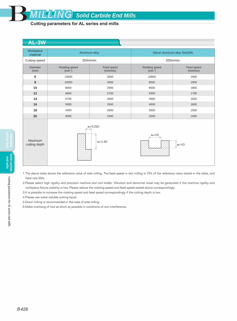
Workpiece material Aluminum alloy Silicon aluminum alloy Si≤10%
Cutting speed 250m/min 200m/min
Diameter(mm)
Rotating speed(min-1)
Feed speed(mm/min)
Rotating speed(min-1)
Feed speed(mm/min)
6 13000 3000 10600 1900
8 10000 3000 8000 1900
10 8000 2900 6500 1850
12 6600 2700 5300 1700
14 5700 2600 4600 1650
16 5000 2550 4000 1600
18 4400 2500 3500 1550
20 4000 2400 3200 1500
Maximum cutting depth
1.The above table shows the reference value of side milling. The feed speed in slot milling is 70% of the reference value stated in the table, and
feed rate 50%.
2.Please select high rigidity and precision machine and tool holder. Vibration and abnormal noise may be generated if the machine rigidity and
workpiece fixture stability is low. Please reduce the rotating speed and feed speed stated above correspondingly.
3.It is possible to increase the rotating speed and feed speed correspondingly if the cutting depth is low.
4.Please use water-soluble cutting liquid.
5.Down milling is recommended in the case of side milling.
6.Make overhang of tool as short as possible in conditions of non-interference.
ae=0.25D
ap=1.5D
ae=1D
ap=1D
AL-3W
Cutting parameters for AL series end m
ills
B
B 428
Solid Carbide End MillsMILLINGMILLING
Indexable m
illing toolsSolid carbide
end mills
Cutting parameters for AL series end mills
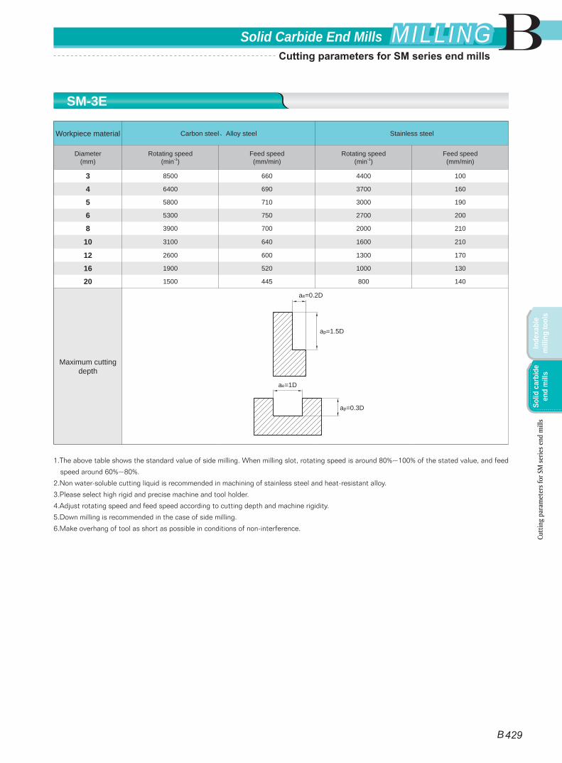
Workpiece material Carbon steel、Alloy steel Stainless steel
Diameter(mm)
Rotating speed(min-1)
Feed speed(mm/min)
Rotating speed(min-1)
Feed speed(mm/min)
3 8500 660 4400 100
4 6400 690 3700 160
5 5800 710 3000 190
6 5300 750 2700 200
8 3900 700 2000 210
10 3100 640 1600 210
12 2600 600 1300 170
16 1900 520 1000 130
20 1500 445 800 140
Maximum cutting depth
1.The above table shows the standard value of side milling. When milling slot, rotating speed is around 80%~100% of the stated value, and feed
speed around 60%~80%.
2.Non water-soluble cutting liquid is recommended in machining of stainless steel and heat-resistant alloy.
3.Please select high rigid and precise machine and tool holder.
4.Adjust rotating speed and feed speed according to cutting depth and machine rigidity.
5.Down milling is recommended in the case of side milling.
6.Make overhang of tool as short as possible in conditions of non-interference.
ae=0.2D
ap=1.5D
ae=1D
ap=0.3D
Cutt
ing
para
met
ers f
or S
M se
ries e
nd m
ills
SM-3E
B
B 429
Solid Carbide End Mills MILLINGMILLING
Inde
xabl
e m
illin
g to
ols
Solid
car
bide
en
d m
ills
Cutting parameters for SM series end mills
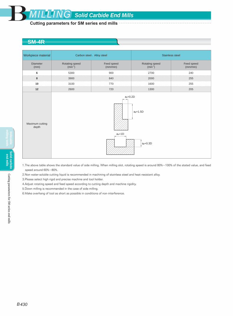
Workpiece material Carbon steel、Alloy steel Stainless steel
Diameter(mm)
Rotating speed(min-1)
Feed speed(mm/min)
Rotating speed(min-1)
Feed speed(mm/min)
6 5300 900 2700 240
8 3900 840 2000 255
10 3100 770 1600 255
12 2600 720 1300 205
Maximum cutting depth
1.The above table shows the standard value of side milling. When milling slot, rotating speed is around 80%~100% of the stated value, and feed
speed around 60%~80%.
2.Non water-soluble cutting liquid is recommended in machining of stainless steel and heat-resistant alloy.
3.Please select high rigid and precise machine and tool holder.
4.Adjust rotating speed and feed speed according to cutting depth and machine rigidity.
5.Down milling is recommended in the case of side milling.
6.Make overhang of tool as short as possible in conditions of non-interference.
ae=0.2D
ap=1.5D
ae=1D
ap=0.3D
Cutting parameters for SM
series end mills
SM-4R
B
B 430
Solid Carbide End MillsMILLINGMILLING
Indexable m
illing toolsSolid carbide
end mills
Cutting parameters for SM series end mills
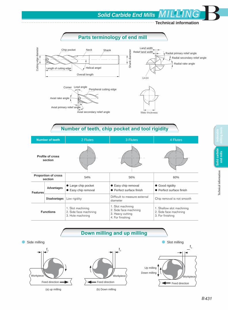
Cutti
ng e
dge
diam
eter NeckChip pocket
Length of cutting edge
Overall length
Helical angel Sha
nk d
iam
eter
Land widthRelief land width Radial primary relief angle
Radial secondary relief angle
Radial rake angle
Corner Lead anglePeripheral cutting edge
Axial rake angle
Axial primary relief angle
Axial secondary relief angle Web thickness
Shank
Number of teeth 2 Flutes 3 Flutes 4 Flutes
Profile of cross section
Proportion of cross section 54% 56% 60%
FeaturesAdvantages
● Large chip pocket● Easy chip removal
● Easy chip removal● Perfect surface finish
● Good rigidity● Perfect surface finish
Disadvantages Low rigidityDifficult to measure external diameter
Chip removal is not smooth
Functions1. Slot machining2. Side face machining3. Hole machining
1. Slot machining2. Side face machining3. Heavy cutting4. For finishing
1. Shallow slot machining2. Side face machining3. For finishing
Tech
nica
l inf
orm
atio
n
● Side milling
fz fz
Workpiece Workpiece
Feed direction Feed direction
(b) Down milling(a) up milling
fz
Workpiece
Feed direction
Up milling
Down milling
● Slot milling
Technical information
Parts terminology of end mill
Number of teeth, chip pocket and tool rigidity
Down milling and up milling
B
B 431
Solid Carbide End Mills MILLINGMILLING
Inde
xabl
e m
illin
g to
ols
Solid
car
bide
en
d m
ills
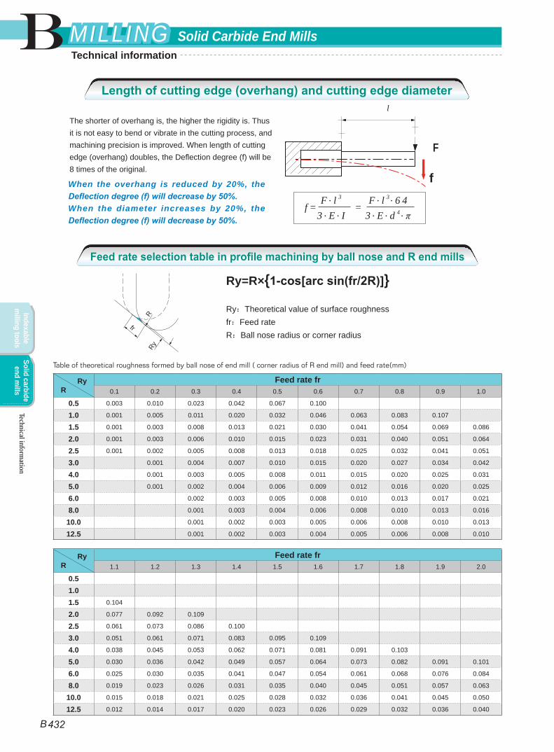
fF . l 3
3 . E . IF . l 3 . 6 4
3 . E . d 4 . πf = =
l
F
The shorter of overhang is, the higher the rigidity is. Thus it is not easy to bend or vibrate in the cutting process, and machining precision is improved. When length of cutting edge (overhang) doubles, the Deflection degree (f) will be 8 times of the original.
When the overhang is reduced by 20%, the Deflection degree (f) will decrease by 50%.When the diameter increases by 20%, the Deflection degree (f) will decrease by 50%.
Technical information
Ry=R×{1-cos[arc sin(fr/2R)]}
Ry:Theoretical value of surface roughnessfr:Feed rateR:Ball nose radius or corner radius
Ry R
Feed rate fr0.1 0.2 0.3 0.4 0.5 0.6 0.7 0.8 0.9 1.0
0.5 0.003 0.010 0.023 0.042 0.067 0.100
1.0 0.001 0.005 0.011 0.020 0.032 0.046 0.063 0.083 0.107
1.5 0.001 0.003 0.008 0.013 0.021 0.030 0.041 0.054 0.069 0.086
2.0 0.001 0.003 0.006 0.010 0.015 0.023 0.031 0.040 0.051 0.064
2.5 0.001 0.002 0.005 0.008 0.013 0.018 0.025 0.032 0.041 0.051
3.0 0.001 0.004 0.007 0.010 0.015 0.020 0.027 0.034 0.042
4.0 0.001 0.003 0.005 0.008 0.011 0.015 0.020 0.025 0.031
5.0 0.001 0.002 0.004 0.006 0.009 0.012 0.016 0.020 0.025
6.0 0.002 0.003 0.005 0.008 0.010 0.013 0.017 0.021
8.0 0.001 0.003 0.004 0.006 0.008 0.010 0.013 0.016
10.0 0.001 0.002 0.003 0.005 0.006 0.008 0.010 0.013
12.5 0.001 0.002 0.003 0.004 0.005 0.006 0.008 0.010
Ry R
Feed rate fr1.1 1.2 1.3 1.4 1.5 1.6 1.7 1.8 1.9 2.0
0.5 1.0 1.5 0.104
2.0 0.077 0.092 0.109
2.5 0.061 0.073 0.086 0.100
3.0 0.051 0.061 0.071 0.083 0.095 0.109
4.0 0.038 0.045 0.053 0.062 0.071 0.081 0.091 0.103
5.0 0.030 0.036 0.042 0.049 0.057 0.064 0.073 0.082 0.091 0.101
6.0 0.025 0.030 0.035 0.041 0.047 0.054 0.061 0.068 0.076 0.084
8.0 0.019 0.023 0.026 0.031 0.035 0.040 0.045 0.051 0.057 0.063
10.0 0.015 0.018 0.021 0.025 0.028 0.032 0.036 0.041 0.045 0.050
12.5 0.012 0.014 0.017 0.020 0.023 0.026 0.029 0.032 0.036 0.040
R
fr
Ry
Table of theoretical roughness formed by ball nose of end mill ( corner radius of R end mill) and feed rate(mm)
Technical information
Length of cutting edge (overhang) and cutting edge diameter
Feed rate selection table in profile machining by ball nose and R end mills
B
B 432
Solid Carbide End MillsMILLINGMILLING
Indexable m
illing toolsSolid carbide
end mills
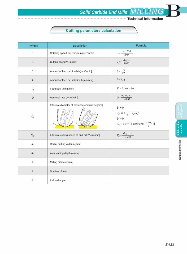
n c·1000n= d·
vc 1000c=d· ·n
fz z·nfz=V f
f f = f z·z
Vf Vf = f z·z ·n=f·n
Q Q= a e·a p· f
1000
deff
deff=2· d·a p-a p2
deff = d·s in [ ±arccos ( )]d-2a p
d
Veff Veff=d eff· ·n
1000
ae
ap
d
z
Symbol Description Formula
Rotating speed per minute n[min-1]r/min
Cutting speed Vc[m/min]
Amount of feed per tooth fz[mm/tooth]
Amount of feed per rotation fz[mm/rev.]
Feed rate Vf[mm/min]
Removal rate Q[cm3/min]
Effective diameter of ball nose end mill deff[mm]
Effective cutting speed of end mill Veff[m/min]
Radial cutting width ae[mm]
Axial cutting depth ap[mm]
Milling diameter[mm]
Number of teeth
Inclined angleTe
chni
cal i
nfor
mat
ion
Cutting parameters calculation
B
B 433
Solid Carbide End Mills MILLINGMILLING
Inde
xabl
e m
illin
g to
ols
Solid
car
bide
en
d m
ills
Technical information
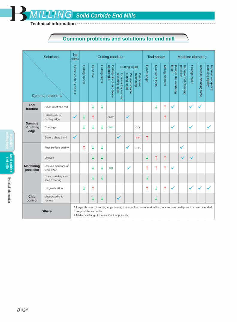
Solutions
Common problems
Tool material Cutting condition Tool shape Machine clamping
Select coated end m
ill
Cutting speed
Feed rate
Cutting depth
Cutting direction ( dow
n / up m
illing )
Cutting liquid
Helical angle
Num
ber of tooth
Milling diam
eter
Reduce the overhang
length
Improve tool clam
ping precision
Change collet
Increase clamping force
Improve w
orkpiece clam
ping rigidity
Increase the amount
of cutting liquid
Water-insoluble
cutting liquid
Dry or w
et m
achiningTool
fracture Fracture of end mill
Damage of cutting
edge
Rapid wear of cutting edge down
Breakage down dry
Severe chips bond wet
Machining precision
Poor surface quality wet
Uneven Uneven side face of workpiece up Burrs, breakage and slice frittering
Large vibration Chip
controlobstructed chip removal
Others1.Large abrasion of cutting edge is easy to cause fracture of end mill or poor surface quality, so it is recommended to regrind the end mills.2.Make overhang of tool as short as possible.
Technical information
Common problems and solutions for end mill
B
B 434
Solid Carbide End MillsMILLINGMILLING
Indexable m
illing toolsSolid carbide
end mills
Technical information