Embed Size (px)
Citation preview
MN0
HMi Operator Interface
User Manual
January 2007
4802014E For more information visit: www.EatonElectrical.com


Important Notice – Please Read
The product discussed in this literature is subject to terms and conditions outlined in Eaton Electrical Inc. selling policies. The sole source governing the rights and remedies of any purchaser of this equipment is the relevant Eaton Electrical Inc. selling policy.
NO WARRANTIES, EXPRESS OR IMPLIED, INCLUDING WARRANTIES OF FITNESS FOR A PARTICULAR PURPOSE OR MERCHANTABILITY, OR WARRANTIES ARISING FROM COURSE OF DEALING OR USAGE OF TRADE, ARE MADE REGARDING THE INFORMATION, RECOMMENDATIONS AND DESCRIPTIONS CONTAINED HEREIN. In no event will Eaton Electrical Inc. be responsible to the purchaser or user in contract, in tort (including negligence), strict liability or otherwise for any special, indirect, incidental or consequential damage or loss whatsoever, including but not limited to damage or loss of use of equipment, plant or power system, cost of capital, loss of power, additional expenses in the use of existing power facilities, or claims against the purchaser or user by its customers resulting from the use of the information, recommendations and descriptions contained herein.
The information contained in this manual is subject to change without notice.
Cover Photo: HMi Operator Interface
MN04802014E For more information visit: www.EatonElectrical.com i
Table of Contents
LIST OF FIGURES . . . . . . . . . . . . . . . . . . . . . . . . . . . . . . . . . . . . . . . . . . . . . . vii
LIST OF TABLES . . . . . . . . . . . . . . . . . . . . . . . . . . . . . . . . . . . . . . . . . . . . . . . xi
CHAPTER 1 — INTRODUCTIONHMi Series Human Machine Interface . . . . . . . . . . . . . . . . . . . . . . . . . . . . . . . . . 1-1Features . . . . . . . . . . . . . . . . . . . . . . . . . . . . . . . . . . . . . . . . . . . . . . . . . . . . . . . . . . 1-1Recommended System Requirements . . . . . . . . . . . . . . . . . . . . . . . . . . . . . . . . . 1-2
CHAPTER 2 — CREATING AND EDITING SCREENSHMisoft Setup . . . . . . . . . . . . . . . . . . . . . . . . . . . . . . . . . . . . . . . . . . . . . . . . . . . . . 2-1Getting Started . . . . . . . . . . . . . . . . . . . . . . . . . . . . . . . . . . . . . . . . . . . . . . . . . . . . 2-1Menu Bar and Toolbar (File). . . . . . . . . . . . . . . . . . . . . . . . . . . . . . . . . . . . . . . . . . 2-5Menu Bar and Toolbar (Edit) . . . . . . . . . . . . . . . . . . . . . . . . . . . . . . . . . . . . . . . . . 2-7Menu Bar and Toolbar (View) . . . . . . . . . . . . . . . . . . . . . . . . . . . . . . . . . . . . . . . . 2-12Menu Bar and Toolbar (Element). . . . . . . . . . . . . . . . . . . . . . . . . . . . . . . . . . . . . . 2-19Menu Bar and Toolbar (Screen) . . . . . . . . . . . . . . . . . . . . . . . . . . . . . . . . . . . . . . . 2-22Menu Bar and Toolbar (Tools) . . . . . . . . . . . . . . . . . . . . . . . . . . . . . . . . . . . . . . . . 2-25Menu Bar and Toolbar (Options) . . . . . . . . . . . . . . . . . . . . . . . . . . . . . . . . . . . . . . 2-28How to Use Multi-Language Function. . . . . . . . . . . . . . . . . . . . . . . . . . . . . . . . . . 2-46How to Use Print Function . . . . . . . . . . . . . . . . . . . . . . . . . . . . . . . . . . . . . . . . . . . 2-56How to Use Hard Copy Function . . . . . . . . . . . . . . . . . . . . . . . . . . . . . . . . . . . . . . 2-61Menu Bar and Toolbar (Window). . . . . . . . . . . . . . . . . . . . . . . . . . . . . . . . . . . . . . 2-67
CHAPTER 3 — ELEMENT FUNCTIONHow to Select an Element . . . . . . . . . . . . . . . . . . . . . . . . . . . . . . . . . . . . . . . . . . . 3-1Property Window Attributes. . . . . . . . . . . . . . . . . . . . . . . . . . . . . . . . . . . . . . . . . . 3-3General Buttons . . . . . . . . . . . . . . . . . . . . . . . . . . . . . . . . . . . . . . . . . . . . . . . . . . . 3-4Multistate Buttons. . . . . . . . . . . . . . . . . . . . . . . . . . . . . . . . . . . . . . . . . . . . . . . . . . 3-6Set Value Button . . . . . . . . . . . . . . . . . . . . . . . . . . . . . . . . . . . . . . . . . . . . . . . . . . . 3-7Set Constant Button . . . . . . . . . . . . . . . . . . . . . . . . . . . . . . . . . . . . . . . . . . . . . . . . 3-8Increment / Decrement . . . . . . . . . . . . . . . . . . . . . . . . . . . . . . . . . . . . . . . . . . . . . . 3-9Goto Screen / Previous Page (Previous View) Buttons . . . . . . . . . . . . . . . . . . . . 3-10System Function Button . . . . . . . . . . . . . . . . . . . . . . . . . . . . . . . . . . . . . . . . . . . . . 3-11Meter Element . . . . . . . . . . . . . . . . . . . . . . . . . . . . . . . . . . . . . . . . . . . . . . . . . . . . . 3-13Bar Element . . . . . . . . . . . . . . . . . . . . . . . . . . . . . . . . . . . . . . . . . . . . . . . . . . . . . . . 3-14Pipe Element . . . . . . . . . . . . . . . . . . . . . . . . . . . . . . . . . . . . . . . . . . . . . . . . . . . . . . 3-17Pie Element . . . . . . . . . . . . . . . . . . . . . . . . . . . . . . . . . . . . . . . . . . . . . . . . . . . . . . . 3-20Indicator . . . . . . . . . . . . . . . . . . . . . . . . . . . . . . . . . . . . . . . . . . . . . . . . . . . . . . . . . . 3-21Data Display. . . . . . . . . . . . . . . . . . . . . . . . . . . . . . . . . . . . . . . . . . . . . . . . . . . . . . . 3-23Numeric Display . . . . . . . . . . . . . . . . . . . . . . . . . . . . . . . . . . . . . . . . . . . . . . . . . . . 3-24Character Display . . . . . . . . . . . . . . . . . . . . . . . . . . . . . . . . . . . . . . . . . . . . . . . . . . 3-25Date Display. . . . . . . . . . . . . . . . . . . . . . . . . . . . . . . . . . . . . . . . . . . . . . . . . . . . . . . 3-25Time Display . . . . . . . . . . . . . . . . . . . . . . . . . . . . . . . . . . . . . . . . . . . . . . . . . . . . . . 3-25Day-of-Week Display. . . . . . . . . . . . . . . . . . . . . . . . . . . . . . . . . . . . . . . . . . . . . . . . 3-25Prestored Message . . . . . . . . . . . . . . . . . . . . . . . . . . . . . . . . . . . . . . . . . . . . . . . . . 3-26Moving Sign . . . . . . . . . . . . . . . . . . . . . . . . . . . . . . . . . . . . . . . . . . . . . . . . . . . . . . 3-26Graph Display . . . . . . . . . . . . . . . . . . . . . . . . . . . . . . . . . . . . . . . . . . . . . . . . . . . . . 3-27Static Graphic . . . . . . . . . . . . . . . . . . . . . . . . . . . . . . . . . . . . . . . . . . . . . . . . . . . . . 3-27Animated Graphic . . . . . . . . . . . . . . . . . . . . . . . . . . . . . . . . . . . . . . . . . . . . . . . . . . 3-29
ii For more information visit: www.EatonElectrical.com MN04802014E
Dynamic Line . . . . . . . . . . . . . . . . . . . . . . . . . . . . . . . . . . . . . . . . . . . . . . . . . . . . . . 3-30Dynamic Rectangle . . . . . . . . . . . . . . . . . . . . . . . . . . . . . . . . . . . . . . . . . . . . . . . . . 3-31Dynamic Ellipse . . . . . . . . . . . . . . . . . . . . . . . . . . . . . . . . . . . . . . . . . . . . . . . . . . . . 3-32Input Element . . . . . . . . . . . . . . . . . . . . . . . . . . . . . . . . . . . . . . . . . . . . . . . . . . . . . . 3-33Numeric Entry. . . . . . . . . . . . . . . . . . . . . . . . . . . . . . . . . . . . . . . . . . . . . . . . . . . . . . 3-34Character Entry. . . . . . . . . . . . . . . . . . . . . . . . . . . . . . . . . . . . . . . . . . . . . . . . . . . . . 3-36Curve Element . . . . . . . . . . . . . . . . . . . . . . . . . . . . . . . . . . . . . . . . . . . . . . . . . . . . . 3-36Trend Graph . . . . . . . . . . . . . . . . . . . . . . . . . . . . . . . . . . . . . . . . . . . . . . . . . . . . . . . 3-37X-Y Chart. . . . . . . . . . . . . . . . . . . . . . . . . . . . . . . . . . . . . . . . . . . . . . . . . . . . . . . . . . 3-39Sampling Element . . . . . . . . . . . . . . . . . . . . . . . . . . . . . . . . . . . . . . . . . . . . . . . . . . 3-41Historical Trend Graph. . . . . . . . . . . . . . . . . . . . . . . . . . . . . . . . . . . . . . . . . . . . . . . 3-44Historical Data Table . . . . . . . . . . . . . . . . . . . . . . . . . . . . . . . . . . . . . . . . . . . . . . . . 3-47Historical Event Table. . . . . . . . . . . . . . . . . . . . . . . . . . . . . . . . . . . . . . . . . . . . . . . . 3-49Alarm Element . . . . . . . . . . . . . . . . . . . . . . . . . . . . . . . . . . . . . . . . . . . . . . . . . . . . . 3-50Alarm History Table . . . . . . . . . . . . . . . . . . . . . . . . . . . . . . . . . . . . . . . . . . . . . . . . . 3-51Active Alarm List . . . . . . . . . . . . . . . . . . . . . . . . . . . . . . . . . . . . . . . . . . . . . . . . . . . 3-51Alarm Frequency Table . . . . . . . . . . . . . . . . . . . . . . . . . . . . . . . . . . . . . . . . . . . . . . 3-52Alarm Moving Sign . . . . . . . . . . . . . . . . . . . . . . . . . . . . . . . . . . . . . . . . . . . . . . . . . 3-52Graphic Element. . . . . . . . . . . . . . . . . . . . . . . . . . . . . . . . . . . . . . . . . . . . . . . . . . . . 3-53Line . . . . . . . . . . . . . . . . . . . . . . . . . . . . . . . . . . . . . . . . . . . . . . . . . . . . . . . . . . . . . . 3-53Rectangle . . . . . . . . . . . . . . . . . . . . . . . . . . . . . . . . . . . . . . . . . . . . . . . . . . . . . . . . . 3-53Circle . . . . . . . . . . . . . . . . . . . . . . . . . . . . . . . . . . . . . . . . . . . . . . . . . . . . . . . . . . . . . 3-54Polygon . . . . . . . . . . . . . . . . . . . . . . . . . . . . . . . . . . . . . . . . . . . . . . . . . . . . . . . . . . . 3-55Arc . . . . . . . . . . . . . . . . . . . . . . . . . . . . . . . . . . . . . . . . . . . . . . . . . . . . . . . . . . . . . . . 3-56Text . . . . . . . . . . . . . . . . . . . . . . . . . . . . . . . . . . . . . . . . . . . . . . . . . . . . . . . . . . . . . . 3-57Scale . . . . . . . . . . . . . . . . . . . . . . . . . . . . . . . . . . . . . . . . . . . . . . . . . . . . . . . . . . . . . 3-58Table . . . . . . . . . . . . . . . . . . . . . . . . . . . . . . . . . . . . . . . . . . . . . . . . . . . . . . . . . . . . . 3-60Keypad Element . . . . . . . . . . . . . . . . . . . . . . . . . . . . . . . . . . . . . . . . . . . . . . . . . . . . 3-61
CHAPTER 4 — MACRO FUNCTIONMacro Types . . . . . . . . . . . . . . . . . . . . . . . . . . . . . . . . . . . . . . . . . . . . . . . . . . . . . . . 4-2Macro Editing . . . . . . . . . . . . . . . . . . . . . . . . . . . . . . . . . . . . . . . . . . . . . . . . . . . . . . 4-3Edit. . . . . . . . . . . . . . . . . . . . . . . . . . . . . . . . . . . . . . . . . . . . . . . . . . . . . . . . . . . . . . . 4-4Command . . . . . . . . . . . . . . . . . . . . . . . . . . . . . . . . . . . . . . . . . . . . . . . . . . . . . . . . . 4-5Keypad Entry . . . . . . . . . . . . . . . . . . . . . . . . . . . . . . . . . . . . . . . . . . . . . . . . . . . . . . 4-5Macro Operation . . . . . . . . . . . . . . . . . . . . . . . . . . . . . . . . . . . . . . . . . . . . . . . . . . . 4-6Definition. . . . . . . . . . . . . . . . . . . . . . . . . . . . . . . . . . . . . . . . . . . . . . . . . . . . . . . . . . 4-6Arithmetic Operation . . . . . . . . . . . . . . . . . . . . . . . . . . . . . . . . . . . . . . . . . . . . . . . . 4-6+, FADD . . . . . . . . . . . . . . . . . . . . . . . . . . . . . . . . . . . . . . . . . . . . . . . . . . . . . . . . . . . 4-7-, FSUB . . . . . . . . . . . . . . . . . . . . . . . . . . . . . . . . . . . . . . . . . . . . . . . . . . . . . . . . . . . 4-8*, FMUL. . . . . . . . . . . . . . . . . . . . . . . . . . . . . . . . . . . . . . . . . . . . . . . . . . . . . . . . . . . 4-9/, FDIV . . . . . . . . . . . . . . . . . . . . . . . . . . . . . . . . . . . . . . . . . . . . . . . . . . . . . . . . . . . . 4-10Get Remainder . . . . . . . . . . . . . . . . . . . . . . . . . . . . . . . . . . . . . . . . . . . . . . . . . . . . . 4-11ADDSUMW . . . . . . . . . . . . . . . . . . . . . . . . . . . . . . . . . . . . . . . . . . . . . . . . . . . . . . . . 4-12Logical Operation . . . . . . . . . . . . . . . . . . . . . . . . . . . . . . . . . . . . . . . . . . . . . . . . . . . 4-12| Operand . . . . . . . . . . . . . . . . . . . . . . . . . . . . . . . . . . . . . . . . . . . . . . . . . . . . . . . . . 4-13&& Operand . . . . . . . . . . . . . . . . . . . . . . . . . . . . . . . . . . . . . . . . . . . . . . . . . . . . . . . 4-13^ Operand . . . . . . . . . . . . . . . . . . . . . . . . . . . . . . . . . . . . . . . . . . . . . . . . . . . . . . . . . 4-14<< Operand . . . . . . . . . . . . . . . . . . . . . . . . . . . . . . . . . . . . . . . . . . . . . . . . . . . . . . . . 4-15>> Operand . . . . . . . . . . . . . . . . . . . . . . . . . . . . . . . . . . . . . . . . . . . . . . . . . . . . . . . . 4-15Data Transfer . . . . . . . . . . . . . . . . . . . . . . . . . . . . . . . . . . . . . . . . . . . . . . . . . . . . . . 4-15BMOV . . . . . . . . . . . . . . . . . . . . . . . . . . . . . . . . . . . . . . . . . . . . . . . . . . . . . . . . . . . . 4-16
MN04802014E For more information visit: www.EatonElectrical.com iii
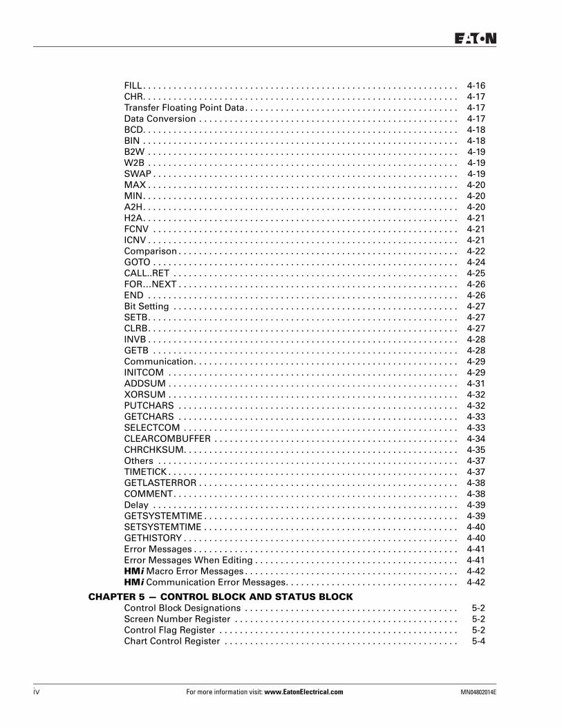
FILL. . . . . . . . . . . . . . . . . . . . . . . . . . . . . . . . . . . . . . . . . . . . . . . . . . . . . . . . . . . . . . 4-16CHR. . . . . . . . . . . . . . . . . . . . . . . . . . . . . . . . . . . . . . . . . . . . . . . . . . . . . . . . . . . . . . 4-17Transfer Floating Point Data. . . . . . . . . . . . . . . . . . . . . . . . . . . . . . . . . . . . . . . . . . 4-17Data Conversion . . . . . . . . . . . . . . . . . . . . . . . . . . . . . . . . . . . . . . . . . . . . . . . . . . . 4-17BCD. . . . . . . . . . . . . . . . . . . . . . . . . . . . . . . . . . . . . . . . . . . . . . . . . . . . . . . . . . . . . . 4-18BIN . . . . . . . . . . . . . . . . . . . . . . . . . . . . . . . . . . . . . . . . . . . . . . . . . . . . . . . . . . . . . . 4-18B2W . . . . . . . . . . . . . . . . . . . . . . . . . . . . . . . . . . . . . . . . . . . . . . . . . . . . . . . . . . . . . 4-19W2B . . . . . . . . . . . . . . . . . . . . . . . . . . . . . . . . . . . . . . . . . . . . . . . . . . . . . . . . . . . . . 4-19SWAP . . . . . . . . . . . . . . . . . . . . . . . . . . . . . . . . . . . . . . . . . . . . . . . . . . . . . . . . . . . . 4-19MAX . . . . . . . . . . . . . . . . . . . . . . . . . . . . . . . . . . . . . . . . . . . . . . . . . . . . . . . . . . . . . 4-20MIN. . . . . . . . . . . . . . . . . . . . . . . . . . . . . . . . . . . . . . . . . . . . . . . . . . . . . . . . . . . . . . 4-20A2H. . . . . . . . . . . . . . . . . . . . . . . . . . . . . . . . . . . . . . . . . . . . . . . . . . . . . . . . . . . . . . 4-20H2A. . . . . . . . . . . . . . . . . . . . . . . . . . . . . . . . . . . . . . . . . . . . . . . . . . . . . . . . . . . . . . 4-21FCNV . . . . . . . . . . . . . . . . . . . . . . . . . . . . . . . . . . . . . . . . . . . . . . . . . . . . . . . . . . . . 4-21ICNV . . . . . . . . . . . . . . . . . . . . . . . . . . . . . . . . . . . . . . . . . . . . . . . . . . . . . . . . . . . . . 4-21Comparison . . . . . . . . . . . . . . . . . . . . . . . . . . . . . . . . . . . . . . . . . . . . . . . . . . . . . . . 4-22GOTO . . . . . . . . . . . . . . . . . . . . . . . . . . . . . . . . . . . . . . . . . . . . . . . . . . . . . . . . . . . . 4-24CALL..RET . . . . . . . . . . . . . . . . . . . . . . . . . . . . . . . . . . . . . . . . . . . . . . . . . . . . . . . . 4-25FOR…NEXT . . . . . . . . . . . . . . . . . . . . . . . . . . . . . . . . . . . . . . . . . . . . . . . . . . . . . . . 4-26END . . . . . . . . . . . . . . . . . . . . . . . . . . . . . . . . . . . . . . . . . . . . . . . . . . . . . . . . . . . . . 4-26Bit Setting . . . . . . . . . . . . . . . . . . . . . . . . . . . . . . . . . . . . . . . . . . . . . . . . . . . . . . . . 4-27SETB. . . . . . . . . . . . . . . . . . . . . . . . . . . . . . . . . . . . . . . . . . . . . . . . . . . . . . . . . . . . . 4-27CLRB. . . . . . . . . . . . . . . . . . . . . . . . . . . . . . . . . . . . . . . . . . . . . . . . . . . . . . . . . . . . . 4-27INVB . . . . . . . . . . . . . . . . . . . . . . . . . . . . . . . . . . . . . . . . . . . . . . . . . . . . . . . . . . . . . 4-28GETB . . . . . . . . . . . . . . . . . . . . . . . . . . . . . . . . . . . . . . . . . . . . . . . . . . . . . . . . . . . . 4-28Communication. . . . . . . . . . . . . . . . . . . . . . . . . . . . . . . . . . . . . . . . . . . . . . . . . . . . 4-29INITCOM . . . . . . . . . . . . . . . . . . . . . . . . . . . . . . . . . . . . . . . . . . . . . . . . . . . . . . . . . 4-29ADDSUM . . . . . . . . . . . . . . . . . . . . . . . . . . . . . . . . . . . . . . . . . . . . . . . . . . . . . . . . . 4-31XORSUM . . . . . . . . . . . . . . . . . . . . . . . . . . . . . . . . . . . . . . . . . . . . . . . . . . . . . . . . . 4-32PUTCHARS . . . . . . . . . . . . . . . . . . . . . . . . . . . . . . . . . . . . . . . . . . . . . . . . . . . . . . . 4-32GETCHARS . . . . . . . . . . . . . . . . . . . . . . . . . . . . . . . . . . . . . . . . . . . . . . . . . . . . . . . 4-33SELECTCOM . . . . . . . . . . . . . . . . . . . . . . . . . . . . . . . . . . . . . . . . . . . . . . . . . . . . . . 4-33CLEARCOMBUFFER . . . . . . . . . . . . . . . . . . . . . . . . . . . . . . . . . . . . . . . . . . . . . . . . 4-34CHRCHKSUM. . . . . . . . . . . . . . . . . . . . . . . . . . . . . . . . . . . . . . . . . . . . . . . . . . . . . . 4-35Others . . . . . . . . . . . . . . . . . . . . . . . . . . . . . . . . . . . . . . . . . . . . . . . . . . . . . . . . . . . 4-37TIMETICK . . . . . . . . . . . . . . . . . . . . . . . . . . . . . . . . . . . . . . . . . . . . . . . . . . . . . . . . . 4-37GETLASTERROR . . . . . . . . . . . . . . . . . . . . . . . . . . . . . . . . . . . . . . . . . . . . . . . . . . . 4-38COMMENT. . . . . . . . . . . . . . . . . . . . . . . . . . . . . . . . . . . . . . . . . . . . . . . . . . . . . . . . 4-38Delay . . . . . . . . . . . . . . . . . . . . . . . . . . . . . . . . . . . . . . . . . . . . . . . . . . . . . . . . . . . . 4-39GETSYSTEMTIME . . . . . . . . . . . . . . . . . . . . . . . . . . . . . . . . . . . . . . . . . . . . . . . . . . 4-39SETSYSTEMTIME . . . . . . . . . . . . . . . . . . . . . . . . . . . . . . . . . . . . . . . . . . . . . . . . . . 4-40GETHISTORY . . . . . . . . . . . . . . . . . . . . . . . . . . . . . . . . . . . . . . . . . . . . . . . . . . . . . . 4-40Error Messages . . . . . . . . . . . . . . . . . . . . . . . . . . . . . . . . . . . . . . . . . . . . . . . . . . . . 4-41Error Messages When Editing . . . . . . . . . . . . . . . . . . . . . . . . . . . . . . . . . . . . . . . . 4-41HMi Macro Error Messages . . . . . . . . . . . . . . . . . . . . . . . . . . . . . . . . . . . . . . . . . . 4-42HMi Communication Error Messages. . . . . . . . . . . . . . . . . . . . . . . . . . . . . . . . . . 4-42
CHAPTER 5 — CONTROL BLOCK AND STATUS BLOCKControl Block Designations . . . . . . . . . . . . . . . . . . . . . . . . . . . . . . . . . . . . . . . . . . 5-2Screen Number Register . . . . . . . . . . . . . . . . . . . . . . . . . . . . . . . . . . . . . . . . . . . . 5-2Control Flag Register . . . . . . . . . . . . . . . . . . . . . . . . . . . . . . . . . . . . . . . . . . . . . . . 5-2Chart Control Register . . . . . . . . . . . . . . . . . . . . . . . . . . . . . . . . . . . . . . . . . . . . . . 5-4
iv For more information visit: www.EatonElectrical.com MN04802014E
HMi Operator Interface
MN04802014E For more information visit: www.EatonElectrical.com v
January 2007
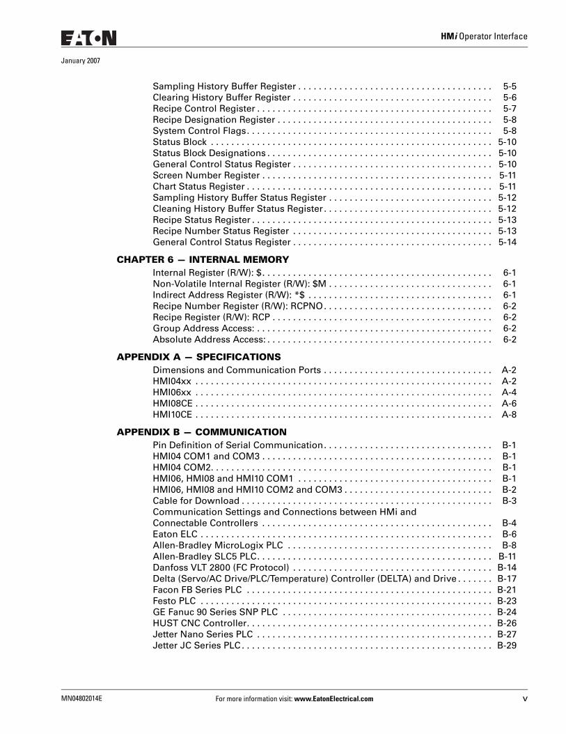
Sampling History Buffer Register . . . . . . . . . . . . . . . . . . . . . . . . . . . . . . . . . . . . . . 5-5Clearing History Buffer Register . . . . . . . . . . . . . . . . . . . . . . . . . . . . . . . . . . . . . . . 5-6Recipe Control Register . . . . . . . . . . . . . . . . . . . . . . . . . . . . . . . . . . . . . . . . . . . . . . 5-7Recipe Designation Register . . . . . . . . . . . . . . . . . . . . . . . . . . . . . . . . . . . . . . . . . . 5-8System Control Flags. . . . . . . . . . . . . . . . . . . . . . . . . . . . . . . . . . . . . . . . . . . . . . . . 5-8Status Block . . . . . . . . . . . . . . . . . . . . . . . . . . . . . . . . . . . . . . . . . . . . . . . . . . . . . . . 5-10Status Block Designations . . . . . . . . . . . . . . . . . . . . . . . . . . . . . . . . . . . . . . . . . . . . 5-10General Control Status Register . . . . . . . . . . . . . . . . . . . . . . . . . . . . . . . . . . . . . . . 5-10Screen Number Register . . . . . . . . . . . . . . . . . . . . . . . . . . . . . . . . . . . . . . . . . . . . . 5-11Chart Status Register . . . . . . . . . . . . . . . . . . . . . . . . . . . . . . . . . . . . . . . . . . . . . . . . 5-11Sampling History Buffer Status Register . . . . . . . . . . . . . . . . . . . . . . . . . . . . . . . . 5-12Cleaning History Buffer Status Register . . . . . . . . . . . . . . . . . . . . . . . . . . . . . . . . . 5-12Recipe Status Register . . . . . . . . . . . . . . . . . . . . . . . . . . . . . . . . . . . . . . . . . . . . . . . 5-13Recipe Number Status Register . . . . . . . . . . . . . . . . . . . . . . . . . . . . . . . . . . . . . . . 5-13General Control Status Register . . . . . . . . . . . . . . . . . . . . . . . . . . . . . . . . . . . . . . . 5-14
CHAPTER 6 — INTERNAL MEMORYInternal Register (R/W): $. . . . . . . . . . . . . . . . . . . . . . . . . . . . . . . . . . . . . . . . . . . . . 6-1Non-Volatile Internal Register (R/W): $M . . . . . . . . . . . . . . . . . . . . . . . . . . . . . . . . 6-1Indirect Address Register (R/W): *$ . . . . . . . . . . . . . . . . . . . . . . . . . . . . . . . . . . . . 6-1Recipe Number Register (R/W): RCPNO. . . . . . . . . . . . . . . . . . . . . . . . . . . . . . . . . 6-2Recipe Register (R/W): RCP . . . . . . . . . . . . . . . . . . . . . . . . . . . . . . . . . . . . . . . . . . . 6-2Group Address Access: . . . . . . . . . . . . . . . . . . . . . . . . . . . . . . . . . . . . . . . . . . . . . . 6-2Absolute Address Access: . . . . . . . . . . . . . . . . . . . . . . . . . . . . . . . . . . . . . . . . . . . . 6-2
APPENDIX A — SPECIFICATIONSDimensions and Communication Ports . . . . . . . . . . . . . . . . . . . . . . . . . . . . . . . . . A-2HMI04xx . . . . . . . . . . . . . . . . . . . . . . . . . . . . . . . . . . . . . . . . . . . . . . . . . . . . . . . . . . A-2HMI06xx . . . . . . . . . . . . . . . . . . . . . . . . . . . . . . . . . . . . . . . . . . . . . . . . . . . . . . . . . . A-4HMI08CE . . . . . . . . . . . . . . . . . . . . . . . . . . . . . . . . . . . . . . . . . . . . . . . . . . . . . . . . . . A-6HMI10CE . . . . . . . . . . . . . . . . . . . . . . . . . . . . . . . . . . . . . . . . . . . . . . . . . . . . . . . . . . A-8
APPENDIX B — COMMUNICATIONPin Definition of Serial Communication. . . . . . . . . . . . . . . . . . . . . . . . . . . . . . . . . B-1HMI04 COM1 and COM3 . . . . . . . . . . . . . . . . . . . . . . . . . . . . . . . . . . . . . . . . . . . . . B-1HMI04 COM2. . . . . . . . . . . . . . . . . . . . . . . . . . . . . . . . . . . . . . . . . . . . . . . . . . . . . . . B-1HMI06, HMI08 and HMI10 COM1 . . . . . . . . . . . . . . . . . . . . . . . . . . . . . . . . . . . . . . B-1HMI06, HMI08 and HMI10 COM2 and COM3 . . . . . . . . . . . . . . . . . . . . . . . . . . . . . B-2Cable for Download . . . . . . . . . . . . . . . . . . . . . . . . . . . . . . . . . . . . . . . . . . . . . . . . . B-3Communication Settings and Connections between HMi and Connectable Controllers . . . . . . . . . . . . . . . . . . . . . . . . . . . . . . . . . . . . . . . . . . . . . B-4Eaton ELC . . . . . . . . . . . . . . . . . . . . . . . . . . . . . . . . . . . . . . . . . . . . . . . . . . . . . . . . . B-6Allen-Bradley MicroLogix PLC . . . . . . . . . . . . . . . . . . . . . . . . . . . . . . . . . . . . . . . . B-8Allen-Bradley SLC5 PLC. . . . . . . . . . . . . . . . . . . . . . . . . . . . . . . . . . . . . . . . . . . . . . B-11Danfoss VLT 2800 (FC Protocol) . . . . . . . . . . . . . . . . . . . . . . . . . . . . . . . . . . . . . . . B-14Delta (Servo/AC Drive/PLC/Temperature) Controller (DELTA) and Drive . . . . . . . B-17Facon FB Series PLC . . . . . . . . . . . . . . . . . . . . . . . . . . . . . . . . . . . . . . . . . . . . . . . . B-21Festo PLC . . . . . . . . . . . . . . . . . . . . . . . . . . . . . . . . . . . . . . . . . . . . . . . . . . . . . . . . . B-23GE Fanuc 90 Series SNP PLC . . . . . . . . . . . . . . . . . . . . . . . . . . . . . . . . . . . . . . . . . B-24HUST CNC Controller. . . . . . . . . . . . . . . . . . . . . . . . . . . . . . . . . . . . . . . . . . . . . . . . B-26Jetter Nano Series PLC . . . . . . . . . . . . . . . . . . . . . . . . . . . . . . . . . . . . . . . . . . . . . . B-27Jetter JC Series PLC . . . . . . . . . . . . . . . . . . . . . . . . . . . . . . . . . . . . . . . . . . . . . . . . . B-29
HMi Operator Interface
January 2007
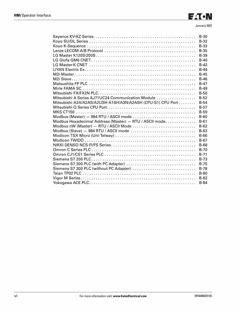
Keyence KV/KZ Series. . . . . . . . . . . . . . . . . . . . . . . . . . . . . . . . . . . . . . . . . . . . . . . B-30Koyo SU/DL Series . . . . . . . . . . . . . . . . . . . . . . . . . . . . . . . . . . . . . . . . . . . . . . . . . B-32Koyo K-Sequence . . . . . . . . . . . . . . . . . . . . . . . . . . . . . . . . . . . . . . . . . . . . . . . . . . B-33Lenze LECOM-A/B Protocol . . . . . . . . . . . . . . . . . . . . . . . . . . . . . . . . . . . . . . . . . . B-35LG Master K120S/200S . . . . . . . . . . . . . . . . . . . . . . . . . . . . . . . . . . . . . . . . . . . . . . B-39LG Glofa GM6 CNET . . . . . . . . . . . . . . . . . . . . . . . . . . . . . . . . . . . . . . . . . . . . . . . . B-40LG Master-K CNET . . . . . . . . . . . . . . . . . . . . . . . . . . . . . . . . . . . . . . . . . . . . . . . . . B-42LIYAN Electric Ex . . . . . . . . . . . . . . . . . . . . . . . . . . . . . . . . . . . . . . . . . . . . . . . . . . . B-44M2i Master. . . . . . . . . . . . . . . . . . . . . . . . . . . . . . . . . . . . . . . . . . . . . . . . . . . . . . . . B-45M2i Slave . . . . . . . . . . . . . . . . . . . . . . . . . . . . . . . . . . . . . . . . . . . . . . . . . . . . . . . . . B-46Matsushita FP PLC . . . . . . . . . . . . . . . . . . . . . . . . . . . . . . . . . . . . . . . . . . . . . . . . . B-47Mirle FAMA SC . . . . . . . . . . . . . . . . . . . . . . . . . . . . . . . . . . . . . . . . . . . . . . . . . . . . B-49Mitsubishi FX/FX2N PLC. . . . . . . . . . . . . . . . . . . . . . . . . . . . . . . . . . . . . . . . . . . . . B-50Mitsubishi A Series AJ71UC24 Communication Module . . . . . . . . . . . . . . . . . . B-52Mitsubishi A2A/A2AS/A2USH A1SH/A3N/A2ASH (CPU-S1) CPU Port . . . . . . . . B-54Mitsubishi Q Series CPU Port. . . . . . . . . . . . . . . . . . . . . . . . . . . . . . . . . . . . . . . . . B-57MKS CT150 . . . . . . . . . . . . . . . . . . . . . . . . . . . . . . . . . . . . . . . . . . . . . . . . . . . . . . . B-59Modbus (Master) — 984 RTU / ASCII mode . . . . . . . . . . . . . . . . . . . . . . . . . . . . . B-60Modbus Hexadecimal Address (Master) — RTU / ASCII mode. . . . . . . . . . . . . . B-61Modbus nW (Master) — RTU / ASCII Mode . . . . . . . . . . . . . . . . . . . . . . . . . . . . . B-62Modbus (Slave) — 984 RTU / ASCII mode . . . . . . . . . . . . . . . . . . . . . . . . . . . . . . B-63Modicon TSX Micro (Uni-Telway) . . . . . . . . . . . . . . . . . . . . . . . . . . . . . . . . . . . . . B-66Modicon TWIDO . . . . . . . . . . . . . . . . . . . . . . . . . . . . . . . . . . . . . . . . . . . . . . . . . . . B-67NIKKI DENSO NCS-FI/FS Series. . . . . . . . . . . . . . . . . . . . . . . . . . . . . . . . . . . . . . . B-68Omron C Series PLC . . . . . . . . . . . . . . . . . . . . . . . . . . . . . . . . . . . . . . . . . . . . . . . . B-70Omron CJ1/CS1 Series PLC . . . . . . . . . . . . . . . . . . . . . . . . . . . . . . . . . . . . . . . . . . B-71Siemens S7 200 PLC . . . . . . . . . . . . . . . . . . . . . . . . . . . . . . . . . . . . . . . . . . . . . . . . B-73Siemens S7 300 PLC (with PC Adapter) . . . . . . . . . . . . . . . . . . . . . . . . . . . . . . . . B-75Siemens S7 300 PLC (without PC Adapter) . . . . . . . . . . . . . . . . . . . . . . . . . . . . . B-78Taian TP02 PLC . . . . . . . . . . . . . . . . . . . . . . . . . . . . . . . . . . . . . . . . . . . . . . . . . . . . B-80Vigor M Series . . . . . . . . . . . . . . . . . . . . . . . . . . . . . . . . . . . . . . . . . . . . . . . . . . . . . B-82Yokogawa ACE PLC. . . . . . . . . . . . . . . . . . . . . . . . . . . . . . . . . . . . . . . . . . . . . . . . . B-84
vi For more information visit: www.EatonElectrical.com MN04802014E
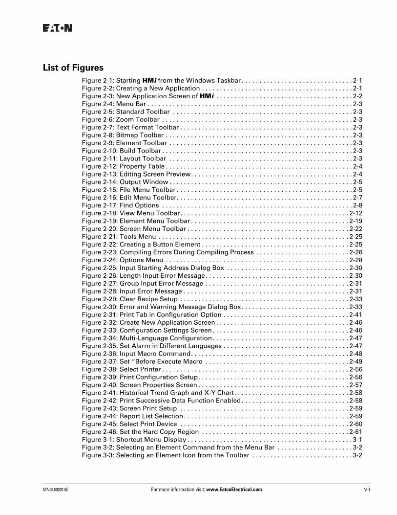
List of Figures
Figure 2-1: Starting HMi from the Windows Taskbar . . . . . . . . . . . . . . . . . . . . . . . . . . . . . . . 2-1Figure 2-2: Creating a New Application . . . . . . . . . . . . . . . . . . . . . . . . . . . . . . . . . . . . . . . . . . 2-1Figure 2-3: New Application Screen of HMi . . . . . . . . . . . . . . . . . . . . . . . . . . . . . . . . . . . . . . 2-2Figure 2-4: Menu Bar . . . . . . . . . . . . . . . . . . . . . . . . . . . . . . . . . . . . . . . . . . . . . . . . . . . . . . . . . 2-3Figure 2-5: Standard Toolbar . . . . . . . . . . . . . . . . . . . . . . . . . . . . . . . . . . . . . . . . . . . . . . . . . . 2-3Figure 2-6: Zoom Toolbar . . . . . . . . . . . . . . . . . . . . . . . . . . . . . . . . . . . . . . . . . . . . . . . . . . . . . 2-3Figure 2-7: Text Format Toolbar . . . . . . . . . . . . . . . . . . . . . . . . . . . . . . . . . . . . . . . . . . . . . . . . 2-3Figure 2-8: Bitmap Toolbar . . . . . . . . . . . . . . . . . . . . . . . . . . . . . . . . . . . . . . . . . . . . . . . . . . . . 2-3Figure 2-9: Element Toolbar . . . . . . . . . . . . . . . . . . . . . . . . . . . . . . . . . . . . . . . . . . . . . . . . . . . 2-3Figure 2-10: Build Toolbar . . . . . . . . . . . . . . . . . . . . . . . . . . . . . . . . . . . . . . . . . . . . . . . . . . . . . 2-3Figure 2-11: Layout Toolbar . . . . . . . . . . . . . . . . . . . . . . . . . . . . . . . . . . . . . . . . . . . . . . . . . . . 2-3Figure 2-12: Property Table . . . . . . . . . . . . . . . . . . . . . . . . . . . . . . . . . . . . . . . . . . . . . . . . . . . . 2-4Figure 2-13: Editing Screen Preview. . . . . . . . . . . . . . . . . . . . . . . . . . . . . . . . . . . . . . . . . . . . . 2-4Figure 2-14: Output Window . . . . . . . . . . . . . . . . . . . . . . . . . . . . . . . . . . . . . . . . . . . . . . . . . . . 2-5Figure 2-15: File Menu Toolbar . . . . . . . . . . . . . . . . . . . . . . . . . . . . . . . . . . . . . . . . . . . . . . . . . 2-5Figure 2-16: Edit Menu Toolbar. . . . . . . . . . . . . . . . . . . . . . . . . . . . . . . . . . . . . . . . . . . . . . . . . 2-7Figure 2-17: Find Options . . . . . . . . . . . . . . . . . . . . . . . . . . . . . . . . . . . . . . . . . . . . . . . . . . . . . 2-8Figure 2-18: View Menu Toolbar. . . . . . . . . . . . . . . . . . . . . . . . . . . . . . . . . . . . . . . . . . . . . . . 2-12Figure 2-19: Element Menu Toolbar . . . . . . . . . . . . . . . . . . . . . . . . . . . . . . . . . . . . . . . . . . . . 2-19Figure 2-20: Screen Menu Toolbar . . . . . . . . . . . . . . . . . . . . . . . . . . . . . . . . . . . . . . . . . . . . . 2-22Figure 2-21: Tools Menu . . . . . . . . . . . . . . . . . . . . . . . . . . . . . . . . . . . . . . . . . . . . . . . . . . . . . 2-25Figure 2-22: Creating a Button Element . . . . . . . . . . . . . . . . . . . . . . . . . . . . . . . . . . . . . . . . . 2-25Figure 2-23: Compiling Errors During Compiling Process . . . . . . . . . . . . . . . . . . . . . . . . . . 2-26Figure 2-24: Options Menu . . . . . . . . . . . . . . . . . . . . . . . . . . . . . . . . . . . . . . . . . . . . . . . . . . . 2-28Figure 2-25: Input Starting Address Dialog Box . . . . . . . . . . . . . . . . . . . . . . . . . . . . . . . . . . 2-30Figure 2-26: Length Input Error Message. . . . . . . . . . . . . . . . . . . . . . . . . . . . . . . . . . . . . . . . 2-30Figure 2-27: Group Input Error Message . . . . . . . . . . . . . . . . . . . . . . . . . . . . . . . . . . . . . . . . 2-31Figure 2-28: Input Error Message . . . . . . . . . . . . . . . . . . . . . . . . . . . . . . . . . . . . . . . . . . . . . . 2-31Figure 2-29: Clear Recipe Setup . . . . . . . . . . . . . . . . . . . . . . . . . . . . . . . . . . . . . . . . . . . . . . . 2-33Figure 2-30: Error and Warning Message Dialog Box. . . . . . . . . . . . . . . . . . . . . . . . . . . . . . 2-33Figure 2-31: Print Tab in Configuration Option . . . . . . . . . . . . . . . . . . . . . . . . . . . . . . . . . . . 2-41Figure 2-32: Create New Application Screen . . . . . . . . . . . . . . . . . . . . . . . . . . . . . . . . . . . . . 2-46Figure 2-33: Configuration Settings Screen . . . . . . . . . . . . . . . . . . . . . . . . . . . . . . . . . . . . . . 2-46Figure 2-34: Multi-Language Configuration . . . . . . . . . . . . . . . . . . . . . . . . . . . . . . . . . . . . . . 2-47Figure 2-35: Set Alarm in Different Languages . . . . . . . . . . . . . . . . . . . . . . . . . . . . . . . . . . . 2-47Figure 2-36: Input Macro Command. . . . . . . . . . . . . . . . . . . . . . . . . . . . . . . . . . . . . . . . . . . . 2-48Figure 2-37: Set “Before Execute Macro . . . . . . . . . . . . . . . . . . . . . . . . . . . . . . . . . . . . . . . . 2-49Figure 2-38: Select Printer . . . . . . . . . . . . . . . . . . . . . . . . . . . . . . . . . . . . . . . . . . . . . . . . . . . . 2-56Figure 2-39: Print Configuration Setup. . . . . . . . . . . . . . . . . . . . . . . . . . . . . . . . . . . . . . . . . . 2-56Figure 2-40: Screen Properties Screen . . . . . . . . . . . . . . . . . . . . . . . . . . . . . . . . . . . . . . . . . . 2-57Figure 2-41: Historical Trend Graph and X-Y Chart. . . . . . . . . . . . . . . . . . . . . . . . . . . . . . . . 2-58Figure 2-42: Print Successive Data Function Enabled . . . . . . . . . . . . . . . . . . . . . . . . . . . . . . 2-58Figure 2-43: Screen Print Setup . . . . . . . . . . . . . . . . . . . . . . . . . . . . . . . . . . . . . . . . . . . . . . . 2-59Figure 2-44: Report List Selection . . . . . . . . . . . . . . . . . . . . . . . . . . . . . . . . . . . . . . . . . . . . . . 2-59Figure 2-45: Select Print Device . . . . . . . . . . . . . . . . . . . . . . . . . . . . . . . . . . . . . . . . . . . . . . . 2-60Figure 2-46: Set the Hard Copy Region . . . . . . . . . . . . . . . . . . . . . . . . . . . . . . . . . . . . . . . . . 2-61Figure 3-1: Shortcut Menu Display . . . . . . . . . . . . . . . . . . . . . . . . . . . . . . . . . . . . . . . . . . . . . . 3-1Figure 3-2: Selecting an Element Command from the Menu Bar . . . . . . . . . . . . . . . . . . . . . 3-2Figure 3-3: Selecting an Element Icon from the Toolbar . . . . . . . . . . . . . . . . . . . . . . . . . . . . 3-2
MN04802014E For more information visit: www.EatonElectrical.com vii
HMi Operator Interface
January 2007
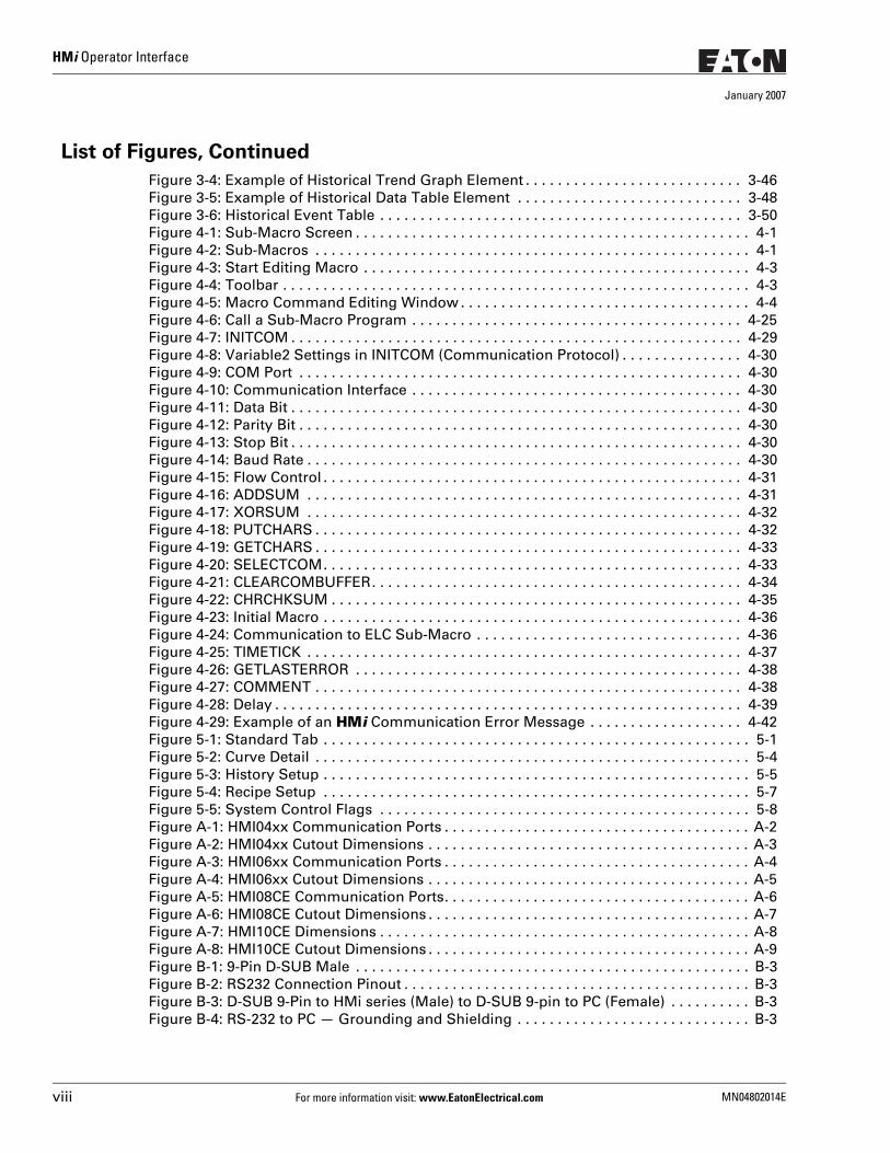
List of Figures, Continued
Figure 3-4: Example of Historical Trend Graph Element . . . . . . . . . . . . . . . . . . . . . . . . . . . 3-46Figure 3-5: Example of Historical Data Table Element . . . . . . . . . . . . . . . . . . . . . . . . . . . . 3-48Figure 3-6: Historical Event Table . . . . . . . . . . . . . . . . . . . . . . . . . . . . . . . . . . . . . . . . . . . . . 3-50Figure 4-1: Sub-Macro Screen . . . . . . . . . . . . . . . . . . . . . . . . . . . . . . . . . . . . . . . . . . . . . . . . . 4-1Figure 4-2: Sub-Macros . . . . . . . . . . . . . . . . . . . . . . . . . . . . . . . . . . . . . . . . . . . . . . . . . . . . . . 4-1Figure 4-3: Start Editing Macro . . . . . . . . . . . . . . . . . . . . . . . . . . . . . . . . . . . . . . . . . . . . . . . . 4-3Figure 4-4: Toolbar . . . . . . . . . . . . . . . . . . . . . . . . . . . . . . . . . . . . . . . . . . . . . . . . . . . . . . . . . . 4-3Figure 4-5: Macro Command Editing Window . . . . . . . . . . . . . . . . . . . . . . . . . . . . . . . . . . . . 4-4Figure 4-6: Call a Sub-Macro Program . . . . . . . . . . . . . . . . . . . . . . . . . . . . . . . . . . . . . . . . . 4-25Figure 4-7: INITCOM . . . . . . . . . . . . . . . . . . . . . . . . . . . . . . . . . . . . . . . . . . . . . . . . . . . . . . . . 4-29Figure 4-8: Variable2 Settings in INITCOM (Communication Protocol) . . . . . . . . . . . . . . . 4-30Figure 4-9: COM Port . . . . . . . . . . . . . . . . . . . . . . . . . . . . . . . . . . . . . . . . . . . . . . . . . . . . . . . 4-30Figure 4-10: Communication Interface . . . . . . . . . . . . . . . . . . . . . . . . . . . . . . . . . . . . . . . . . 4-30Figure 4-11: Data Bit . . . . . . . . . . . . . . . . . . . . . . . . . . . . . . . . . . . . . . . . . . . . . . . . . . . . . . . . 4-30Figure 4-12: Parity Bit . . . . . . . . . . . . . . . . . . . . . . . . . . . . . . . . . . . . . . . . . . . . . . . . . . . . . . . 4-30Figure 4-13: Stop Bit . . . . . . . . . . . . . . . . . . . . . . . . . . . . . . . . . . . . . . . . . . . . . . . . . . . . . . . . 4-30Figure 4-14: Baud Rate . . . . . . . . . . . . . . . . . . . . . . . . . . . . . . . . . . . . . . . . . . . . . . . . . . . . . . 4-30Figure 4-15: Flow Control . . . . . . . . . . . . . . . . . . . . . . . . . . . . . . . . . . . . . . . . . . . . . . . . . . . . 4-31Figure 4-16: ADDSUM . . . . . . . . . . . . . . . . . . . . . . . . . . . . . . . . . . . . . . . . . . . . . . . . . . . . . . 4-31Figure 4-17: XORSUM . . . . . . . . . . . . . . . . . . . . . . . . . . . . . . . . . . . . . . . . . . . . . . . . . . . . . . 4-32Figure 4-18: PUTCHARS . . . . . . . . . . . . . . . . . . . . . . . . . . . . . . . . . . . . . . . . . . . . . . . . . . . . . 4-32Figure 4-19: GETCHARS . . . . . . . . . . . . . . . . . . . . . . . . . . . . . . . . . . . . . . . . . . . . . . . . . . . . . 4-33Figure 4-20: SELECTCOM. . . . . . . . . . . . . . . . . . . . . . . . . . . . . . . . . . . . . . . . . . . . . . . . . . . . 4-33Figure 4-21: CLEARCOMBUFFER. . . . . . . . . . . . . . . . . . . . . . . . . . . . . . . . . . . . . . . . . . . . . . 4-34Figure 4-22: CHRCHKSUM . . . . . . . . . . . . . . . . . . . . . . . . . . . . . . . . . . . . . . . . . . . . . . . . . . . 4-35Figure 4-23: Initial Macro . . . . . . . . . . . . . . . . . . . . . . . . . . . . . . . . . . . . . . . . . . . . . . . . . . . . 4-36Figure 4-24: Communication to ELC Sub-Macro . . . . . . . . . . . . . . . . . . . . . . . . . . . . . . . . . 4-36Figure 4-25: TIMETICK . . . . . . . . . . . . . . . . . . . . . . . . . . . . . . . . . . . . . . . . . . . . . . . . . . . . . . 4-37Figure 4-26: GETLASTERROR . . . . . . . . . . . . . . . . . . . . . . . . . . . . . . . . . . . . . . . . . . . . . . . . 4-38Figure 4-27: COMMENT . . . . . . . . . . . . . . . . . . . . . . . . . . . . . . . . . . . . . . . . . . . . . . . . . . . . . 4-38Figure 4-28: Delay . . . . . . . . . . . . . . . . . . . . . . . . . . . . . . . . . . . . . . . . . . . . . . . . . . . . . . . . . . 4-39Figure 4-29: Example of an HMi Communication Error Message . . . . . . . . . . . . . . . . . . . 4-42Figure 5-1: Standard Tab . . . . . . . . . . . . . . . . . . . . . . . . . . . . . . . . . . . . . . . . . . . . . . . . . . . . . 5-1Figure 5-2: Curve Detail . . . . . . . . . . . . . . . . . . . . . . . . . . . . . . . . . . . . . . . . . . . . . . . . . . . . . . 5-4Figure 5-3: History Setup . . . . . . . . . . . . . . . . . . . . . . . . . . . . . . . . . . . . . . . . . . . . . . . . . . . . . 5-5Figure 5-4: Recipe Setup . . . . . . . . . . . . . . . . . . . . . . . . . . . . . . . . . . . . . . . . . . . . . . . . . . . . . 5-7Figure 5-5: System Control Flags . . . . . . . . . . . . . . . . . . . . . . . . . . . . . . . . . . . . . . . . . . . . . . 5-8Figure A-1: HMI04xx Communication Ports . . . . . . . . . . . . . . . . . . . . . . . . . . . . . . . . . . . . . . A-2Figure A-2: HMI04xx Cutout Dimensions . . . . . . . . . . . . . . . . . . . . . . . . . . . . . . . . . . . . . . . . A-3Figure A-3: HMI06xx Communication Ports . . . . . . . . . . . . . . . . . . . . . . . . . . . . . . . . . . . . . . A-4Figure A-4: HMI06xx Cutout Dimensions . . . . . . . . . . . . . . . . . . . . . . . . . . . . . . . . . . . . . . . . A-5Figure A-5: HMI08CE Communication Ports. . . . . . . . . . . . . . . . . . . . . . . . . . . . . . . . . . . . . . A-6Figure A-6: HMI08CE Cutout Dimensions . . . . . . . . . . . . . . . . . . . . . . . . . . . . . . . . . . . . . . . . A-7Figure A-7: HMI10CE Dimensions . . . . . . . . . . . . . . . . . . . . . . . . . . . . . . . . . . . . . . . . . . . . . . A-8Figure A-8: HMI10CE Cutout Dimensions . . . . . . . . . . . . . . . . . . . . . . . . . . . . . . . . . . . . . . . . A-9Figure B-1: 9-Pin D-SUB Male . . . . . . . . . . . . . . . . . . . . . . . . . . . . . . . . . . . . . . . . . . . . . . . . . B-3Figure B-2: RS232 Connection Pinout . . . . . . . . . . . . . . . . . . . . . . . . . . . . . . . . . . . . . . . . . . . B-3Figure B-3: D-SUB 9-Pin to HMi series (Male) to D-SUB 9-pin to PC (Female) . . . . . . . . . . B-3Figure B-4: RS-232 to PC — Grounding and Shielding . . . . . . . . . . . . . . . . . . . . . . . . . . . . . B-3
viii For more information visit: www.EatonElectrical.com MN04802014E
HMi Operator Interface
January 2007
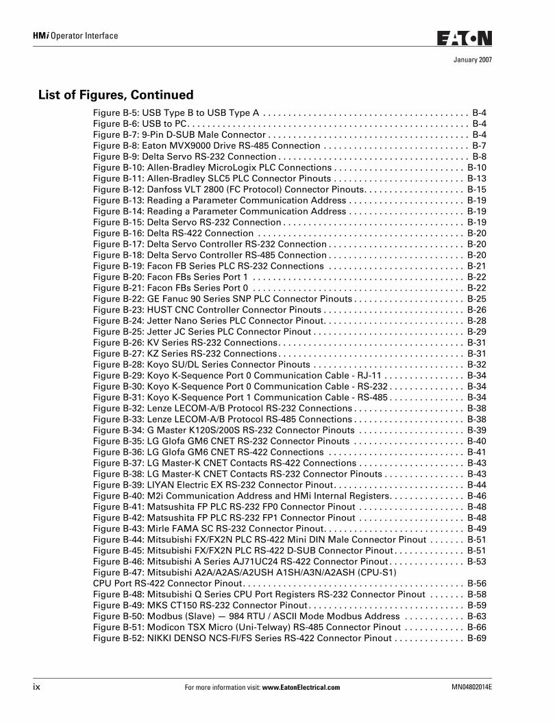
List of Figures, Continued
Figure B-5: USB Type B to USB Type A . . . . . . . . . . . . . . . . . . . . . . . . . . . . . . . . . . . . . . . . . B-4Figure B-6: USB to PC. . . . . . . . . . . . . . . . . . . . . . . . . . . . . . . . . . . . . . . . . . . . . . . . . . . . . . . . B-4Figure B-7: 9-Pin D-SUB Male Connector . . . . . . . . . . . . . . . . . . . . . . . . . . . . . . . . . . . . . . . . B-4Figure B-8: Eaton MVX9000 Drive RS-485 Connection . . . . . . . . . . . . . . . . . . . . . . . . . . . . . B-7Figure B-9: Delta Servo RS-232 Connection . . . . . . . . . . . . . . . . . . . . . . . . . . . . . . . . . . . . . . B-8Figure B-10: Allen-Bradley MicroLogix PLC Connections . . . . . . . . . . . . . . . . . . . . . . . . . . B-10Figure B-11: Allen-Bradley SLC5 PLC Connector Pinouts . . . . . . . . . . . . . . . . . . . . . . . . . . B-13Figure B-12: Danfoss VLT 2800 (FC Protocol) Connector Pinouts. . . . . . . . . . . . . . . . . . . . B-15Figure B-13: Reading a Parameter Communication Address . . . . . . . . . . . . . . . . . . . . . . . B-19Figure B-14: Reading a Parameter Communication Address . . . . . . . . . . . . . . . . . . . . . . . B-19Figure B-15: Delta Servo RS-232 Connection . . . . . . . . . . . . . . . . . . . . . . . . . . . . . . . . . . . . B-19Figure B-16: Delta RS-422 Connection . . . . . . . . . . . . . . . . . . . . . . . . . . . . . . . . . . . . . . . . . B-20Figure B-17: Delta Servo Controller RS-232 Connection . . . . . . . . . . . . . . . . . . . . . . . . . . . B-20Figure B-18: Delta Servo Controller RS-485 Connection . . . . . . . . . . . . . . . . . . . . . . . . . . . B-20Figure B-19: Facon FB Series PLC RS-232 Connections . . . . . . . . . . . . . . . . . . . . . . . . . . . B-21Figure B-20: Facon FBs Series Port 1 . . . . . . . . . . . . . . . . . . . . . . . . . . . . . . . . . . . . . . . . . . B-22Figure B-21: Facon FBs Series Port 0 . . . . . . . . . . . . . . . . . . . . . . . . . . . . . . . . . . . . . . . . . . B-22Figure B-22: GE Fanuc 90 Series SNP PLC Connector Pinouts . . . . . . . . . . . . . . . . . . . . . . B-25Figure B-23: HUST CNC Controller Connector Pinouts . . . . . . . . . . . . . . . . . . . . . . . . . . . . B-26Figure B-24: Jetter Nano Series PLC Connector Pinout. . . . . . . . . . . . . . . . . . . . . . . . . . . . B-28Figure B-25: Jetter JC Series PLC Connector Pinout . . . . . . . . . . . . . . . . . . . . . . . . . . . . . . B-29Figure B-26: KV Series RS-232 Connections. . . . . . . . . . . . . . . . . . . . . . . . . . . . . . . . . . . . . B-31Figure B-27: KZ Series RS-232 Connections . . . . . . . . . . . . . . . . . . . . . . . . . . . . . . . . . . . . . B-31Figure B-28: Koyo SU/DL Series Connector Pinouts . . . . . . . . . . . . . . . . . . . . . . . . . . . . . . B-32Figure B-29: Koyo K-Sequence Port 0 Communication Cable - RJ-11 . . . . . . . . . . . . . . . . B-34Figure B-30: Koyo K-Sequence Port 0 Communication Cable - RS-232 . . . . . . . . . . . . . . . B-34Figure B-31: Koyo K-Sequence Port 1 Communication Cable - RS-485 . . . . . . . . . . . . . . . B-34Figure B-32: Lenze LECOM-A/B Protocol RS-232 Connections . . . . . . . . . . . . . . . . . . . . . . B-38Figure B-33: Lenze LECOM-A/B Protocol RS-485 Connections . . . . . . . . . . . . . . . . . . . . . . B-38Figure B-34: G Master K120S/200S RS-232 Connector Pinouts . . . . . . . . . . . . . . . . . . . . . B-39Figure B-35: LG Glofa GM6 CNET RS-232 Connector Pinouts . . . . . . . . . . . . . . . . . . . . . . B-40Figure B-36: LG Glofa GM6 CNET RS-422 Connections . . . . . . . . . . . . . . . . . . . . . . . . . . . B-41Figure B-37: LG Master-K CNET Contacts RS-422 Connections . . . . . . . . . . . . . . . . . . . . . B-43Figure B-38: LG Master-K CNET Contacts RS-232 Connector Pinouts . . . . . . . . . . . . . . . . B-43Figure B-39: LIYAN Electric EX RS-232 Connector Pinout. . . . . . . . . . . . . . . . . . . . . . . . . . B-44Figure B-40: M2i Communication Address and HMi Internal Registers. . . . . . . . . . . . . . . B-46Figure B-41: Matsushita FP PLC RS-232 FP0 Connector Pinout . . . . . . . . . . . . . . . . . . . . . B-48Figure B-42: Matsushita FP PLC RS-232 FP1 Connector Pinout . . . . . . . . . . . . . . . . . . . . . B-48Figure B-43: Mirle FAMA SC RS-232 Connector Pinout. . . . . . . . . . . . . . . . . . . . . . . . . . . . B-49Figure B-44: Mitsubishi FX/FX2N PLC RS-422 Mini DIN Male Connector Pinout . . . . . . . B-51Figure B-45: Mitsubishi FX/FX2N PLC RS-422 D-SUB Connector Pinout . . . . . . . . . . . . . . B-51Figure B-46: Mitsubishi A Series AJ71UC24 RS-422 Connector Pinout . . . . . . . . . . . . . . . B-53Figure B-47: Mitsubishi A2A/A2AS/A2USH A1SH/A3N/A2ASH (CPU-S1) CPU Port RS-422 Connector Pinout. . . . . . . . . . . . . . . . . . . . . . . . . . . . . . . . . . . . . . . . . . . . B-56Figure B-48: Mitsubishi Q Series CPU Port Registers RS-232 Connector Pinout . . . . . . . B-58Figure B-49: MKS CT150 RS-232 Connector Pinout . . . . . . . . . . . . . . . . . . . . . . . . . . . . . . . B-59Figure B-50: Modbus (Slave) — 984 RTU / ASCII Mode Modbus Address . . . . . . . . . . . . B-63Figure B-51: Modicon TSX Micro (Uni-Telway) RS-485 Connector Pinout . . . . . . . . . . . . B-66Figure B-52: NIKKI DENSO NCS-FI/FS Series RS-422 Connector Pinout . . . . . . . . . . . . . . B-69
ix For more information visit: www.EatonElectrical.com MN04802014E
HMi Operator Interface
January 2007
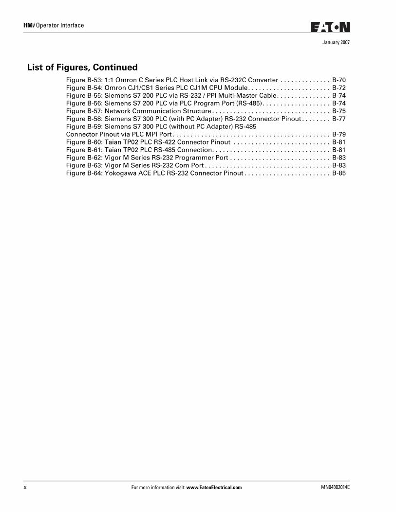
List of Figures, Continued
Figure B-53: 1:1 Omron C Series PLC Host Link via RS-232C Converter . . . . . . . . . . . . . . B-70Figure B-54: Omron CJ1/CS1 Series PLC CJ1M CPU Module. . . . . . . . . . . . . . . . . . . . . . . B-72Figure B-55: Siemens S7 200 PLC via RS-232 / PPI Multi-Master Cable. . . . . . . . . . . . . . . B-74Figure B-56: Siemens S7 200 PLC via PLC Program Port (RS-485). . . . . . . . . . . . . . . . . . . B-74Figure B-57: Network Communication Structure . . . . . . . . . . . . . . . . . . . . . . . . . . . . . . . . . B-75Figure B-58: Siemens S7 300 PLC (with PC Adapter) RS-232 Connector Pinout . . . . . . . . B-77Figure B-59: Siemens S7 300 PLC (without PC Adapter) RS-485 Connector Pinout via PLC MPI Port . . . . . . . . . . . . . . . . . . . . . . . . . . . . . . . . . . . . . . . . . . . . B-79Figure B-60: Taian TP02 PLC RS-422 Connector Pinout . . . . . . . . . . . . . . . . . . . . . . . . . . . B-81Figure B-61: Taian TP02 PLC RS-485 Connection. . . . . . . . . . . . . . . . . . . . . . . . . . . . . . . . . B-81Figure B-62: Vigor M Series RS-232 Programmer Port . . . . . . . . . . . . . . . . . . . . . . . . . . . . B-83Figure B-63: Vigor M Series RS-232 Com Port . . . . . . . . . . . . . . . . . . . . . . . . . . . . . . . . . . . B-83Figure B-64: Yokogawa ACE PLC RS-232 Connector Pinout . . . . . . . . . . . . . . . . . . . . . . . . B-85
x For more information visit: www.EatonElectrical.com MN04802014E
HMi Operator Interface
January 2007
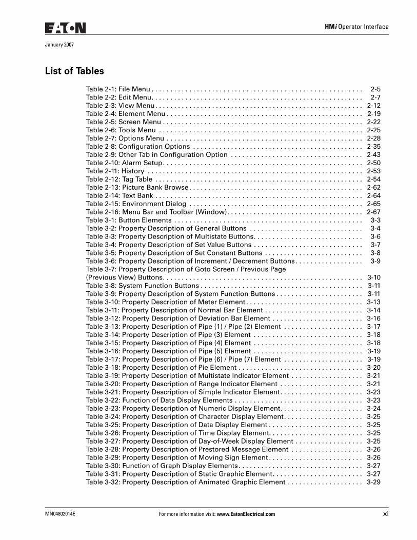
List of Tables
Table 2-1: File Menu . . . . . . . . . . . . . . . . . . . . . . . . . . . . . . . . . . . . . . . . . . . . . . . . . . . . . . . . 2-5Table 2-2: Edit Menu. . . . . . . . . . . . . . . . . . . . . . . . . . . . . . . . . . . . . . . . . . . . . . . . . . . . . . . . 2-7Table 2-3: View Menu. . . . . . . . . . . . . . . . . . . . . . . . . . . . . . . . . . . . . . . . . . . . . . . . . . . . . . . 2-12Table 2-4: Element Menu . . . . . . . . . . . . . . . . . . . . . . . . . . . . . . . . . . . . . . . . . . . . . . . . . . . . 2-19Table 2-5: Screen Menu . . . . . . . . . . . . . . . . . . . . . . . . . . . . . . . . . . . . . . . . . . . . . . . . . . . . . 2-22Table 2-6: Tools Menu . . . . . . . . . . . . . . . . . . . . . . . . . . . . . . . . . . . . . . . . . . . . . . . . . . . . . . 2-25Table 2-7: Options Menu . . . . . . . . . . . . . . . . . . . . . . . . . . . . . . . . . . . . . . . . . . . . . . . . . . . . 2-28Table 2-8: Configuration Options . . . . . . . . . . . . . . . . . . . . . . . . . . . . . . . . . . . . . . . . . . . . . 2-35Table 2-9: Other Tab in Configuration Option . . . . . . . . . . . . . . . . . . . . . . . . . . . . . . . . . . . 2-43Table 2-10: Alarm Setup. . . . . . . . . . . . . . . . . . . . . . . . . . . . . . . . . . . . . . . . . . . . . . . . . . . . . 2-50Table 2-11: History . . . . . . . . . . . . . . . . . . . . . . . . . . . . . . . . . . . . . . . . . . . . . . . . . . . . . . . . . 2-53Table 2-12: Tag Table . . . . . . . . . . . . . . . . . . . . . . . . . . . . . . . . . . . . . . . . . . . . . . . . . . . . . . . 2-54Table 2-13: Picture Bank Browse . . . . . . . . . . . . . . . . . . . . . . . . . . . . . . . . . . . . . . . . . . . . . . 2-62Table 2-14: Text Bank . . . . . . . . . . . . . . . . . . . . . . . . . . . . . . . . . . . . . . . . . . . . . . . . . . . . . . . 2-64Table 2-15: Environment Dialog . . . . . . . . . . . . . . . . . . . . . . . . . . . . . . . . . . . . . . . . . . . . . . 2-65Table 2-16: Menu Bar and Toolbar (Window). . . . . . . . . . . . . . . . . . . . . . . . . . . . . . . . . . . . 2-67Table 3-1: Button Elements . . . . . . . . . . . . . . . . . . . . . . . . . . . . . . . . . . . . . . . . . . . . . . . . . . 3-3Table 3-2: Property Description of General Buttons . . . . . . . . . . . . . . . . . . . . . . . . . . . . . . 3-4Table 3-3: Property Description of Multistate Buttons. . . . . . . . . . . . . . . . . . . . . . . . . . . . . 3-6Table 3-4: Property Description of Set Value Buttons . . . . . . . . . . . . . . . . . . . . . . . . . . . . . 3-7Table 3-5: Property Description of Set Constant Buttons . . . . . . . . . . . . . . . . . . . . . . . . . . 3-8Table 3-6: Property Description of Increment / Decrement Buttons. . . . . . . . . . . . . . . . . . 3-9Table 3-7: Property Description of Goto Screen / Previous Page (Previous View) Buttons. . . . . . . . . . . . . . . . . . . . . . . . . . . . . . . . . . . . . . . . . . . . . . . . . . . . . 3-10Table 3-8: System Function Buttons . . . . . . . . . . . . . . . . . . . . . . . . . . . . . . . . . . . . . . . . . . . 3-11Table 3-9: Property Description of System Function Buttons . . . . . . . . . . . . . . . . . . . . . . . 3-11Table 3-10: Property Description of Meter Element . . . . . . . . . . . . . . . . . . . . . . . . . . . . . . . 3-13Table 3-11: Property Description of Normal Bar Element . . . . . . . . . . . . . . . . . . . . . . . . . . 3-14Table 3-12: Property Description of Deviation Bar Element . . . . . . . . . . . . . . . . . . . . . . . . 3-16Table 3-13: Property Description of Pipe (1) / Pipe (2) Element . . . . . . . . . . . . . . . . . . . . . 3-17Table 3-14: Property Description of Pipe (3) Element . . . . . . . . . . . . . . . . . . . . . . . . . . . . . 3-18Table 3-15: Property Description of Pipe (4) Element . . . . . . . . . . . . . . . . . . . . . . . . . . . . . 3-18Table 3-16: Property Description of Pipe (5) Element . . . . . . . . . . . . . . . . . . . . . . . . . . . . . 3-19Table 3-17: Property Description of Pipe (6) / Pipe (7) Element . . . . . . . . . . . . . . . . . . . . . 3-19Table 3-18: Property Description of Pie Element . . . . . . . . . . . . . . . . . . . . . . . . . . . . . . . . . 3-20Table 3-19: Property Description of Multistate Indicator Element . . . . . . . . . . . . . . . . . . . 3-21Table 3-20: Property Description of Range Indicator Element . . . . . . . . . . . . . . . . . . . . . . 3-21Table 3-21: Property Description of Simple Indicator Element. . . . . . . . . . . . . . . . . . . . . . 3-23Table 3-22: Function of Data Display Elements . . . . . . . . . . . . . . . . . . . . . . . . . . . . . . . . . . 3-23Table 3-23: Property Description of Numeric Display Element. . . . . . . . . . . . . . . . . . . . . . 3-24Table 3-24: Property Description of Character Display Element. . . . . . . . . . . . . . . . . . . . . 3-25Table 3-25: Property Description of Data Display Element . . . . . . . . . . . . . . . . . . . . . . . . . 3-25Table 3-26: Property Description of Time Display Element. . . . . . . . . . . . . . . . . . . . . . . . . 3-25Table 3-27: Property Description of Day-of-Week Display Element . . . . . . . . . . . . . . . . . . 3-25Table 3-28: Property Description of Prestored Message Element . . . . . . . . . . . . . . . . . . . 3-26Table 3-29: Property Description of Moving Sign Element . . . . . . . . . . . . . . . . . . . . . . . . . 3-26Table 3-30: Function of Graph Display Elements. . . . . . . . . . . . . . . . . . . . . . . . . . . . . . . . . 3-27Table 3-31: Property Description of Static Graphic Element. . . . . . . . . . . . . . . . . . . . . . . . 3-27Table 3-32: Property Description of Animated Graphic Element . . . . . . . . . . . . . . . . . . . . 3-29
MN04802014E For more information visit: www.EatonElectrical.com xi
HMi Operator Interface
January 2007
List of Tables, Continued
Table 3-33: Property Description of Dynamic Line Element . . . . . . . . . . . . . . . . . . . . . . . 3-30Table 3-34: Property Description of Dynamic Rectangle Element. . . . . . . . . . . . . . . . . . . 3-31Table 3-35: Property Description of Dynamic Ellipse Element . . . . . . . . . . . . . . . . . . . . . 3-32Table 3-36: Function of Input Elements. . . . . . . . . . . . . . . . . . . . . . . . . . . . . . . . . . . . . . . . 3-33Table 3-37: Property Description of Numeric Entry Element. . . . . . . . . . . . . . . . . . . . . . . 3-34Table 3-38: Property Description of Character Entry Element . . . . . . . . . . . . . . . . . . . . . . 3-36Table 3-39: Function of Curve Elements . . . . . . . . . . . . . . . . . . . . . . . . . . . . . . . . . . . . . . . 3-36Table 3-40: Property Description of Trend Graph Element . . . . . . . . . . . . . . . . . . . . . . . . 3-37Table 3-41: Property Description of X-Y Chart Element . . . . . . . . . . . . . . . . . . . . . . . . . . . 3-39Table 3-42: History Setup Dialog Box . . . . . . . . . . . . . . . . . . . . . . . . . . . . . . . . . . . . . . . . . 3-41Table 3-43: Property Description of Historical Trend Graph Element . . . . . . . . . . . . . . . . 3-44Table 3-44: Property Description of Historical Data Table Element. . . . . . . . . . . . . . . . . . 3-47Table 3-45: Property Description of Historical Event Table Element. . . . . . . . . . . . . . . . . 3-49Table 3-46: Example of Historical Event Table Element. . . . . . . . . . . . . . . . . . . . . . . . . . . 3-49Table 3-47: Function of Alarm Elements . . . . . . . . . . . . . . . . . . . . . . . . . . . . . . . . . . . . . . . 3-50Table 3-48: Property Description of Alarm History Table Element . . . . . . . . . . . . . . . . . . 3-51Table 3-49: Property Description of Active Alarm List Element . . . . . . . . . . . . . . . . . . . . 3-51Table 3-50: Property Description of Alarm Frequency Table Element . . . . . . . . . . . . . . . 3-52Table 3-51: Property Description of Alarm Moving Sign Element . . . . . . . . . . . . . . . . . . 3-52Table 3-52: Property Description of Line Graphic Element . . . . . . . . . . . . . . . . . . . . . . . . 3-53Table 3-53: Property Description of Rectangle Graphic Element . . . . . . . . . . . . . . . . . . . 3-53Table 3-54: Property Description of Circle Graphic Element . . . . . . . . . . . . . . . . . . . . . . . 3-54Table 3-55: Property Description of Polygon Graphic Element . . . . . . . . . . . . . . . . . . . . . 3-55Table 3-56: Property Description of Arc Graphic Element . . . . . . . . . . . . . . . . . . . . . . . . . 3-56Table 3-57: Property Description of Text Graphic Element . . . . . . . . . . . . . . . . . . . . . . . . 3-57Table 3-58: Property Description of Scale Graphic Element . . . . . . . . . . . . . . . . . . . . . . . 3-58Table 3-59: Property Description of Table Graphic Element . . . . . . . . . . . . . . . . . . . . . . . 3-60Table 3-60: Property Description of Keypad Element. . . . . . . . . . . . . . . . . . . . . . . . . . . . . 3-61Table 3-61: Property Description of Keypad Element. . . . . . . . . . . . . . . . . . . . . . . . . . . . . 3-64Table 4-1: Macro Command Table . . . . . . . . . . . . . . . . . . . . . . . . . . . . . . . . . . . . . . . . . . . . 4-2Table 4-2: Macro Definition . . . . . . . . . . . . . . . . . . . . . . . . . . . . . . . . . . . . . . . . . . . . . . . . . 4-6Table 4-3: Arithmetic Command . . . . . . . . . . . . . . . . . . . . . . . . . . . . . . . . . . . . . . . . . . . . . 4-6Table 4-4: Logical Operation Command . . . . . . . . . . . . . . . . . . . . . . . . . . . . . . . . . . . . . . . 4-12Table 4-5: Data Transfer Command . . . . . . . . . . . . . . . . . . . . . . . . . . . . . . . . . . . . . . . . . . . 4-15Table 4-6: Data Conversion Command . . . . . . . . . . . . . . . . . . . . . . . . . . . . . . . . . . . . . . . . 4-17Table 4-7: Comparison Command . . . . . . . . . . . . . . . . . . . . . . . . . . . . . . . . . . . . . . . . . . . . 4-22Table 4-8: Bit Setting Command . . . . . . . . . . . . . . . . . . . . . . . . . . . . . . . . . . . . . . . . . . . . . 4-27Table 4-9: Communication Command. . . . . . . . . . . . . . . . . . . . . . . . . . . . . . . . . . . . . . . . . 4-29Table 5-1: Control Block Designations . . . . . . . . . . . . . . . . . . . . . . . . . . . . . . . . . . . . . . . . 5-2Table 5-2: Designating Screen Number Register (SNIR) - Word 0 . . . . . . . . . . . . . . . . . . 5-2Table 5-3: Control Flag Register (CFR) - Word 1 . . . . . . . . . . . . . . . . . . . . . . . . . . . . . . . . . 5-2Table 5-4: Chart Control Register (CUCR) - Word 2 . . . . . . . . . . . . . . . . . . . . . . . . . . . . . . 5-4Table 5-5: Register for Sampling History Buffer (HBSR) - Control Word 3 . . . . . . . . . . . 5-5Table 5-6: Register for Clearing History Buffer (HBCR) - Control Word 4 . . . . . . . . . . . . 5-6Table 5-7: Recipe Control Register (RECR) - Control Word 5 . . . . . . . . . . . . . . . . . . . . . . 5-7Table 5-8: Register for Designating Recipe Group Number (RBIR) - Control Word 6. . . 5-8Table 5-9: Internal Memory for Recipe Control . . . . . . . . . . . . . . . . . . . . . . . . . . . . . . . . . 5-8Table 5-10: System Control Flag Register (SCFR) - Control Word 7 . . . . . . . . . . . . . . . . . 5-9Table 5-11: Status Block Registers . . . . . . . . . . . . . . . . . . . . . . . . . . . . . . . . . . . . . . . . . . . . 5-10
xii For more information visit: www.EatonElectrical.com MN04802014E
HMi Operator Interface
January 2007
List of Tables, Continued
Table 5-12: Status Register for General Control (GCSR) - Status Word 0. . . . . . . . . . . . . 5-10Table 5-13: Status Register for Screen Number (SNSR) - Status Word 1. . . . . . . . . . . . . 5-11Table 5-14: Status Register of Curve Control (CCSR) - Status Word 2 . . . . . . . . . . . . . . . 5-11Table 5-15: Status Register for Sampling History Buffer (HSSR) - Status Word 3 . . . . . . 5-12Table 5-16: Status Register for Clearing History Buffer (HCSR) - Status Word 4 . . . . . . . 5-12Table 5-17: Recipe Status Register (RESR) - Status Word 5. . . . . . . . . . . . . . . . . . . . . . . . 5-13Table 5-18: Status Register for Recipe Number (RBSR) - Status Word 6 . . . . . . . . . . . . . 5-13Table 5-19: Status Register 2 for General Control (GCSR2) - Status Word 7 . . . . . . . . . . 5-14Table A-1: Model Specifications . . . . . . . . . . . . . . . . . . . . . . . . . . . . . . . . . . . . . . . . . . . . . A-1Table A-2: COM1 and COM3 Ports. . . . . . . . . . . . . . . . . . . . . . . . . . . . . . . . . . . . . . . . . . . . A-2Table A-3: COM2 Port . . . . . . . . . . . . . . . . . . . . . . . . . . . . . . . . . . . . . . . . . . . . . . . . . . . . . . A-3Table A-4: COM2 and COM3 Ports. . . . . . . . . . . . . . . . . . . . . . . . . . . . . . . . . . . . . . . . . . . . A-4Table A-5: COM1 Port . . . . . . . . . . . . . . . . . . . . . . . . . . . . . . . . . . . . . . . . . . . . . . . . . . . . . . A-5Table A-6: COM2 and COM3 Ports. . . . . . . . . . . . . . . . . . . . . . . . . . . . . . . . . . . . . . . . . . . . A-6Table A-7: COM1 Port . . . . . . . . . . . . . . . . . . . . . . . . . . . . . . . . . . . . . . . . . . . . . . . . . . . . . . A-7Table A-8: COM2 and COM3 Ports. . . . . . . . . . . . . . . . . . . . . . . . . . . . . . . . . . . . . . . . . . . . A-8Table A-9: COM1 Port . . . . . . . . . . . . . . . . . . . . . . . . . . . . . . . . . . . . . . . . . . . . . . . . . . . . . . A-9Table B-1: HMI04 COM1 and COM3 Pinout. . . . . . . . . . . . . . . . . . . . . . . . . . . . . . . . . . . . . B-1Table B-2: HMI04 COM2 Pinout . . . . . . . . . . . . . . . . . . . . . . . . . . . . . . . . . . . . . . . . . . . . . . B-1Table B-3: HMI06, HMI08 and HMI10 COM1 Pinout . . . . . . . . . . . . . . . . . . . . . . . . . . . . . . B-1Table B-4: HMI06, HMI08 and HMI10 COM2 and COM3 Pinout . . . . . . . . . . . . . . . . . . . . B-2Table B-5: Communication Settings and Connections. . . . . . . . . . . . . . . . . . . . . . . . . . . . B-4Table B-6: Eaton ELC Registers . . . . . . . . . . . . . . . . . . . . . . . . . . . . . . . . . . . . . . . . . . . . . . B-6Table B-7: Eaton ELC Contacts . . . . . . . . . . . . . . . . . . . . . . . . . . . . . . . . . . . . . . . . . . . . . . . B-6Table B-8: Allen-Bradley MicroLogix PLC Registers. . . . . . . . . . . . . . . . . . . . . . . . . . . . . . B-8Table B-9: Allen-Bradley MicroLogix PLC Contacts . . . . . . . . . . . . . . . . . . . . . . . . . . . . . . B-9Table B-10: Allen-Bradley SLC5 PLC Registers . . . . . . . . . . . . . . . . . . . . . . . . . . . . . . . . . . B-11Table B-11: Allen-Bradley SLC5 PLC Contacts. . . . . . . . . . . . . . . . . . . . . . . . . . . . . . . . . . . B-12Table B-12: Danfoss VLT 2800 (FC Protocol) Registers . . . . . . . . . . . . . . . . . . . . . . . . . . . B-14Table B-13: Danfoss VLT 2800 (FC Protocol) Contacts . . . . . . . . . . . . . . . . . . . . . . . . . . . . B-14Table B-14: Delta (Servo/AC Drive/PLC/Temperature) Controller Registers . . . . . . . . . . . B-17Table B-15: Delta (Servo/AC Drive/PLC/Temperature) Controller Contacts . . . . . . . . . . . B-18Table B-16: Facon FB Series PLC Registers. . . . . . . . . . . . . . . . . . . . . . . . . . . . . . . . . . . . . B-21Table B-17: Facon FB Series PLC Contacts . . . . . . . . . . . . . . . . . . . . . . . . . . . . . . . . . . . . . B-21Table B-18: Festo PLC Registers. . . . . . . . . . . . . . . . . . . . . . . . . . . . . . . . . . . . . . . . . . . . . . B-23Table B-19: Festo PLC Contacts . . . . . . . . . . . . . . . . . . . . . . . . . . . . . . . . . . . . . . . . . . . . . . B-23Table B-20: GE Fanuc 90 Series SNP PLC Registers. . . . . . . . . . . . . . . . . . . . . . . . . . . . . . B-24Table B-21: GE Fanuc 90 Series SNP PLC Contacts . . . . . . . . . . . . . . . . . . . . . . . . . . . . . . B-24Table B-22: HUST CNC Controller Registers . . . . . . . . . . . . . . . . . . . . . . . . . . . . . . . . . . . . B-26Table B-23: HUST CNC Controller Contacts . . . . . . . . . . . . . . . . . . . . . . . . . . . . . . . . . . . . B-26Table B-24: Jetter Nano Series PLC Contacts . . . . . . . . . . . . . . . . . . . . . . . . . . . . . . . . . . . B-28Table B-25: Jetter JC Series PLC Registers . . . . . . . . . . . . . . . . . . . . . . . . . . . . . . . . . . . . . B-29Table B-26: Jetter JC Series PLC Contacts . . . . . . . . . . . . . . . . . . . . . . . . . . . . . . . . . . . . . B-29Table B-27: Keyence KV/KZ Series Registers . . . . . . . . . . . . . . . . . . . . . . . . . . . . . . . . . . . B-30Table B-28: Keyence KV/KZ Series Contacts . . . . . . . . . . . . . . . . . . . . . . . . . . . . . . . . . . . . B-30Table B-29: Koyo SU/DL Series Registers . . . . . . . . . . . . . . . . . . . . . . . . . . . . . . . . . . . . . . B-32Table B-30: Koyo SU/DL Series Contacts . . . . . . . . . . . . . . . . . . . . . . . . . . . . . . . . . . . . . . B-32Table B-31: Koyo K-Sequence Registers . . . . . . . . . . . . . . . . . . . . . . . . . . . . . . . . . . . . . . . B-33Table B-32: Koyo K-Sequence Contacts . . . . . . . . . . . . . . . . . . . . . . . . . . . . . . . . . . . . . . . B-33
xiii For more information visit: www.EatonElectrical.com MN04802014E
HMi Operator Interface
January 2007
List of Tables, Continued
Table B-33: The corresponding registers of CCM2 and K-Sequence . . . . . . . . . . . . . . . . B-34Table B-34: Lenze LECOM-A/B Protocol Read/Write Address . . . . . . . . . . . . . . . . . . . . . . B-35Table B-35: Lenze LECOM-A/B Protocol Contacts . . . . . . . . . . . . . . . . . . . . . . . . . . . . . . . B-36Table B-36: LG Master K120S/200S Registers. . . . . . . . . . . . . . . . . . . . . . . . . . . . . . . . . . . B-39Table B-37: LG Master K120S/200S Contacts . . . . . . . . . . . . . . . . . . . . . . . . . . . . . . . . . . . B-39Table B-38: LG Glofa GM6 CNET Registers. . . . . . . . . . . . . . . . . . . . . . . . . . . . . . . . . . . . . B-40Table B-39: LG Glofa GM6 CNET Contacts . . . . . . . . . . . . . . . . . . . . . . . . . . . . . . . . . . . . . B-40Table B-40: LG Master-K CNET Registers . . . . . . . . . . . . . . . . . . . . . . . . . . . . . . . . . . . . . . B-42Table B-41: LG Master-K CNET Contacts . . . . . . . . . . . . . . . . . . . . . . . . . . . . . . . . . . . . . . . B-42Table B-42: LIYAN Electric EX Registers . . . . . . . . . . . . . . . . . . . . . . . . . . . . . . . . . . . . . . . B-44Table B-43: LIYAN Electric EX Contacts. . . . . . . . . . . . . . . . . . . . . . . . . . . . . . . . . . . . . . . . B-44Table B-44: M2i Master Registers . . . . . . . . . . . . . . . . . . . . . . . . . . . . . . . . . . . . . . . . . . . . B-45Table B-45: Contacts . . . . . . . . . . . . . . . . . . . . . . . . . . . . . . . . . . . . . . . . . . . . . . . . . . . . . . . B-45Table B-46: M2i Slave Registers. . . . . . . . . . . . . . . . . . . . . . . . . . . . . . . . . . . . . . . . . . . . . . B-46Table B-47: M2i Slave Contacts . . . . . . . . . . . . . . . . . . . . . . . . . . . . . . . . . . . . . . . . . . . . . . B-46Table B-48: Matsushita FP PLC Registers . . . . . . . . . . . . . . . . . . . . . . . . . . . . . . . . . . . . . . B-47Table B-49: Matsushita FP PLC Contacts. . . . . . . . . . . . . . . . . . . . . . . . . . . . . . . . . . . . . . . B-47Table B-50: Mirle FAMA SC Registers . . . . . . . . . . . . . . . . . . . . . . . . . . . . . . . . . . . . . . . . . B-49Table B-51: Mirle FAMA SC Contacts . . . . . . . . . . . . . . . . . . . . . . . . . . . . . . . . . . . . . . . . . B-49Table B-52: Mitsubishi FX/FX2N PLC Registers . . . . . . . . . . . . . . . . . . . . . . . . . . . . . . . . . B-50Table B-53: Mitsubishi FX/FX2N PLC Contacts . . . . . . . . . . . . . . . . . . . . . . . . . . . . . . . . . . B-50Table B-54: Mitsubishi A Series AJ71UC24 Registers . . . . . . . . . . . . . . . . . . . . . . . . . . . . B-52Table B-55: Mitsubishi A Series AJ71UC24 Contacts. . . . . . . . . . . . . . . . . . . . . . . . . . . . . B-52Table B-56: Mitsubishi A2A/A2AS/A2USH A1SH/A3N/A2ASH (CPU-S1) CPU Port Registers . . . . . . . . . . . . . . . . . . . . . . . . . . . . . . . . . . . . . . . . . . . . . . . . . . . . . . . . B-55Table B-57: Mitsubishi A2A/A2AS/A2USH A1SH/A3N/A2ASH (CPU-S1) CPU Port Contacts. . . . . . . . . . . . . . . . . . . . . . . . . . . . . . . . . . . . . . . . . . . . . . . . . . . . . . . . . B-55Table B-58: Mitsubishi Q Series CPU Port Registers . . . . . . . . . . . . . . . . . . . . . . . . . . . . . B-57Table B-59: Mitsubishi Q Series CPU Port Registers Contacts . . . . . . . . . . . . . . . . . . . . . B-58Table B-60: MKS CT150 Registers . . . . . . . . . . . . . . . . . . . . . . . . . . . . . . . . . . . . . . . . . . . . B-59Table B-61: MKS CT150 Contacts. . . . . . . . . . . . . . . . . . . . . . . . . . . . . . . . . . . . . . . . . . . . . B-59Table B-62: Modbus (Master) — 984 RTU / ASCII mode Registers . . . . . . . . . . . . . . . . . . B-60Table B-63: Modbus (Master) — 984 RTU / ASCII mode Contacts . . . . . . . . . . . . . . . . . . B-60Table B-64: Modbus Hexadecimal Address (Master) — RTU / ASCII Mode Registers . . B-61Table B-65: Modbus Hexadecimal Address (Master) — RTU / ASCII Mode Contacts . . . B-61Table B-66: Modbus nW (Master) — RTU / ASCII Mode Registers . . . . . . . . . . . . . . . . . . B-62Table B-67: Modbus nW (Master) — RTU / ASCII Mode Contacts . . . . . . . . . . . . . . . . . . B-62Table B-68: Modbus (Slave) — 984 RTU / ASCII Mode Registers . . . . . . . . . . . . . . . . . . . B-63Table B-69: Contacts . . . . . . . . . . . . . . . . . . . . . . . . . . . . . . . . . . . . . . . . . . . . . . . . . . . . . . . B-63Table B-70: Inter Memory Cross-Reference Table . . . . . . . . . . . . . . . . . . . . . . . . . . . . . . . B-64Table B-71: Modicon TSX Micro (Uni-Telway) Registers . . . . . . . . . . . . . . . . . . . . . . . . . . B-66Table B-72: Modicon TSX Micro (Uni-Telway) Contacts . . . . . . . . . . . . . . . . . . . . . . . . . . B-66Table B-73: NIKKI DENSO NCS-FI/FS Series Registers . . . . . . . . . . . . . . . . . . . . . . . . . . . B-68Table B-74: NIKKI DENSO NCS-FI/FS Series Contacts . . . . . . . . . . . . . . . . . . . . . . . . . . . . B-69Table B-75: Omron C Series PLC Registers . . . . . . . . . . . . . . . . . . . . . . . . . . . . . . . . . . . . . B-70Table B-76: Omron C Series PLC Contacts . . . . . . . . . . . . . . . . . . . . . . . . . . . . . . . . . . . . . B-70Table B-77: Omron CJ1/CS1 Series PLC Registers . . . . . . . . . . . . . . . . . . . . . . . . . . . . . . . B-71Table B-78: Omron CJ1/CS1 Series PLC Contacts . . . . . . . . . . . . . . . . . . . . . . . . . . . . . . . B-72Table B-79: Siemens S7 200 PLC Register . . . . . . . . . . . . . . . . . . . . . . . . . . . . . . . . . . . . . B-73
xiv For more information visit: www.EatonElectrical.com MN04802014E
HMi Operator Interface
January 2007
List of Tables, Continued
Table B-80: Siemens S7 200 PLC Contacts . . . . . . . . . . . . . . . . . . . . . . . . . . . . . . . . . . . . . B-73Table B-81: Siemens S7 300 PLC (with PC Adapter) Register . . . . . . . . . . . . . . . . . . . . . . B-76Table B-82: Siemens S7 300 PLC (with PC Adapter) Contacts. . . . . . . . . . . . . . . . . . . . . . B-76Table B-83: Siemens S7 300 PLC (without PC Adapter) Register . . . . . . . . . . . . . . . . . . . B-78Table B-84: Siemens S7 300 PLC (without PC Adapter) Contacts . . . . . . . . . . . . . . . . . . . B-79Table B-85: Taian TP02 PLC Registers . . . . . . . . . . . . . . . . . . . . . . . . . . . . . . . . . . . . . . . . . B-80Table B-86: Taian TP02 PLC Contacts . . . . . . . . . . . . . . . . . . . . . . . . . . . . . . . . . . . . . . . . . B-80Table B-87: Vigor M Series Registers . . . . . . . . . . . . . . . . . . . . . . . . . . . . . . . . . . . . . . . . . B-82Table B-88: Vigor M Series Contacts . . . . . . . . . . . . . . . . . . . . . . . . . . . . . . . . . . . . . . . . . . B-82Table B-89: Yokogawa ACE PLC Registers . . . . . . . . . . . . . . . . . . . . . . . . . . . . . . . . . . . . . B-84Table B-90: Yokogawa ACE PLC Contacts . . . . . . . . . . . . . . . . . . . . . . . . . . . . . . . . . . . . . . B-85
xv For more information visit: www.EatonElectrical.com MN04802014E

HMi Operator Interface
January 2007
xvi For more information visit: www.EatonElectrical.com MN04802014E

HMi Operator Interface
January 2007
Chapter 1 — Introduction
HMi Series Human Machine Interface
HMi is manufactured by adopting high-speed hardware to provide a powerful and programmable interface. HMisoft software is a user-friendly program editor of HMi for Windows. Refer to the following section for an introduction to its features and functions. If you have any suggestions or comments on HMisoft software, please do not hesitate to contact us. We look forward to serving your needs and are willing to offer our best support and service to you.
Features ● PLC Serial Drivers Support
HMi supports more than 20 brands of PLC, including Rockwell, Omron, Siemens, Mitsubishi, etc. All of the newly supported PLC communication protocols can be found on our website(http://www.EatonElectrical.com) for upgrades to meet your requirements. (All other trademarks in this manual are property of their respective companies.)
● Windows Fonts SupportSimplified Chinese, traditional Chinese and English are supported. HMisoft software also provides all fonts used by Windows®.
● Quick Execution and Communication MacroHMisoft handles complicated calculations by executing macros. Additionally, users can create a custom protocol via the COM port.
● Rapid USB Upload/Download HMisoft shortens the upload/download time by using USB Ver1.1.
● RecipesHMi provides a useful recipe editor that is similar to Microsoft Excel. Multiple recipes can be edited simultaneously (size limit is 64K). If you need to download multiple recipes simultaneously, HMi can swap internal memory. After you finish editing the recipes, you can download the recipes individually.
● Support Multiple PLCs ConnectionsConnect to multiple controllers using the HMi’s three communications ports.
If a PC is connected to an HMi, then the HMi on-line simulation feature allows users to develop and debug software on a PC connected to HMi before downloading to HMi.
● Off-line SimulationThe HMi off-line simulation feature allows users to develop and debug software on a stand-alone PC before downloading to HMi.
● Multiple Security Protection HMi provides passwords to protect the designer’s intellectual property rights and also for users to set user priority for important components. Only the users whose priority is higher than the component can use the component.
● USB Host Port (USB Host) EquippedHMi has a built-in USB Host interface for the connection to USB disk, card reader and printer with a USB socket. You can save data, copy a program, print the screen immediately and increase the data storage space.
MN04802014E For more information visit: www.EatonElectrical.com 1-1
HMi Operator Interface
January 2007
● Multi-language SupportEight available languages can be selected and used without installing a multi-lingual operating system. It is easy for the users to switch the desired language via HMi or the external controller. Furthermore, Unicode editing is supported, therefore, it is convenient for the user to create and edit more quickly.
Recommended System Requirements ● Intel® Pentium III, 500MHz or greater ● 256MB RAM ● Windows® 2000 & Windows® XP ● 100 MB free hard disk space ● RS232 port ● USB connection
1-2 For more information visit: www.EatonElectrical.com MN04802014E
HMi Operator Interface
January 2007
Chapter 2 — Creating and Editing Screens
HMisoft Setup
This chapter introduces the general functions of the HMisoft screen editor. Detailed information for each function is discussed in following chapters.
Getting Started
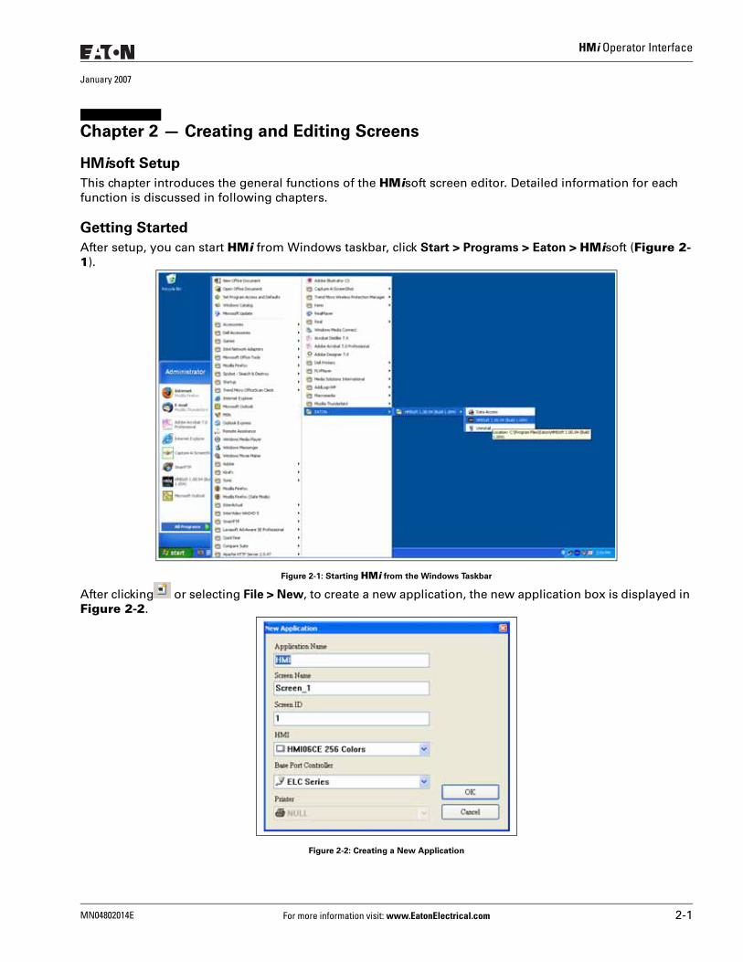
After setup, you can start HMi from Windows taskbar, click Start > Programs > Eaton > HMisoft (Figure 2-1).
Figure 2-1: Starting HMi from the Windows Taskbar
After clicking or selecting File > New, to create a new application, the new application box is displayed in Figure 2-2.
Figure 2-2: Creating a New Application
MN04802014E For more information visit: www.EatonElectrical.com 2-1
HMi Operator Interface
January 2007
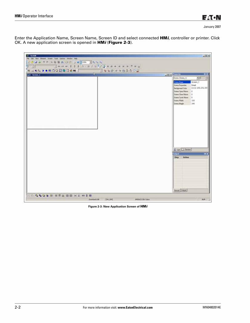
Enter the Application Name, Screen Name, Screen ID and select connected HMi, controller or printer. Click OK. A new application screen is opened in HMi (Figure 2-3).
Figure 2-3: New Application Screen of HMi
2-2 For more information visit: www.EatonElectrical.com MN04802014E
HMi Operator Interface
January 2007
There are five parts in the following HMi application window:
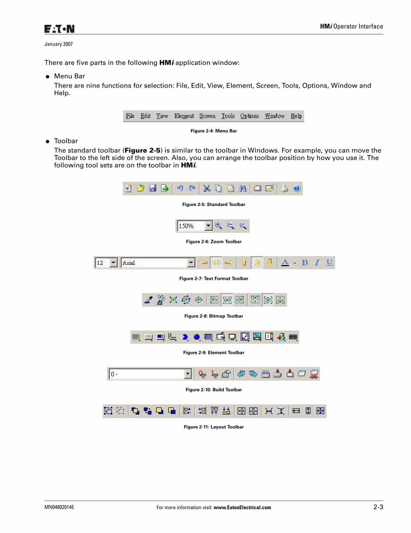
● Menu BarThere are nine functions for selection: File, Edit, View, Element, Screen, Tools, Options, Window and Help.
Figure 2-4: Menu Bar
● Toolbar The standard toolbar (Figure 2-5) is similar to the toolbar in Windows. For example, you can move the Toolbar to the left side of the screen. Also, you can arrange the toolbar position by how you use it. The following tool sets are on the toolbar in HMi.
Figure 2-5: Standard Toolbar
Figure 2-6: Zoom Toolbar
Figure 2-7: Text Format Toolbar
Figure 2-8: Bitmap Toolbar
Figure 2-9: Element Toolbar
Figure 2-10: Build Toolbar
Figure 2-11: Layout Toolbar
MN04802014E For more information visit: www.EatonElectrical.com 2-3
HMi Operator Interface
January 2007
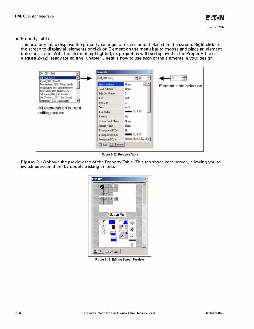
● Property Table The property table displays the property settings for each element placed on the screen. Right click on the screen to display all elements or click on Element on the menu bar to choose and place an element onto the screen. With the element highlighted, its properties will be displayed in the Property Table (Figure 2-12), ready for editing. Chapter 3 details how to use each of the elements in your design.
Figure 2-12: Property Table
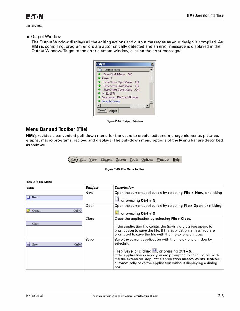
Figure 2-13 shows the preview tab of the Property Table. This tab shoes each screen, allowing you to switch between them by double clicking on one.
Figure 2-13: Editing Screen Preview
2-4 For more information visit: www.EatonElectrical.com MN04802014E
HMi Operator Interface
January 2007
● Output WindowThe Output Window displays all the editing actions and output messages as your design is compiled. As HMi is compiling, program errors are automatically detected and an error message is displayed in the Output Window. To get to the error element window, click on the error message.
Figure 2-14: Output Window
Menu Bar and Toolbar (File)
HMi provides a convenient pull-down menu for the users to create, edit and manage elements, pictures, graphs, macro programs, recipes and displays. The pull-down menu options of the Menu bar are described as follows:
Figure 2-15: File Menu Toolbar
Table 2-1: File Menu
Icon Subject Description
New Open the current application by selecting File > New, or clicking
, or pressing Ctrl + N.Open Open the current application by selecting File > Open, or clicking
, or pressing Ctrl + O.Close Close the application by selecting File > Close.
If the application file exists, the Saving dialog box opens to prompt you to save the file. If the application is new, you are prompted to save the file with the file extension .dop.
Save Save the current application with the file extension .dop by selecting
File > Save, or clicking , or pressing Ctrl + S.If the application is new, you are prompted to save the file with the file extension .dop. If the application already exists, HMi will automatically save the application without displaying a dialog box.
MN04802014E For more information visit: www.EatonElectrical.com 2-5
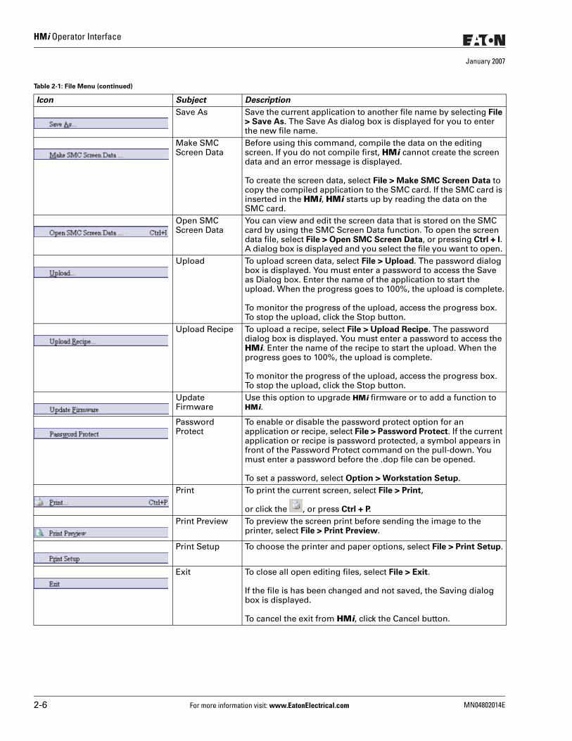
HMi Operator Interface
January 2007
Save As Save the current application to another file name by selecting File > Save As. The Save As dialog box is displayed for you to enter the new file name.
Make SMC Screen Data
Before using this command, compile the data on the editing screen. If you do not compile first, HMi cannot create the screen data and an error message is displayed.
To create the screen data, select File > Make SMC Screen Data to copy the compiled application to the SMC card. If the SMC card is inserted in the HMi, HMi starts up by reading the data on the SMC card.
Open SMC Screen Data
You can view and edit the screen data that is stored on the SMC card by using the SMC Screen Data function. To open the screen data file, select File > Open SMC Screen Data, or pressing Ctrl + I. A dialog box is displayed and you select the file you want to open.
Upload To upload screen data, select File > Upload. The password dialog box is displayed. You must enter a password to access the Save as Dialog box. Enter the name of the application to start the upload. When the progress goes to 100%, the upload is complete.
To monitor the progress of the upload, access the progress box. To stop the upload, click the Stop button.
Upload Recipe To upload a recipe, select File > Upload Recipe. The password dialog box is displayed. You must enter a password to access the HMi. Enter the name of the recipe to start the upload. When the progress goes to 100%, the upload is complete.
To monitor the progress of the upload, access the progress box. To stop the upload, click the Stop button.
Update Firmware
Use this option to upgrade HMi firmware or to add a function to HMi.
Password Protect
To enable or disable the password protect option for an application or recipe, select File > Password Protect. If the current application or recipe is password protected, a symbol appears in front of the Password Protect command on the pull-down. You must enter a password before the .dop file can be opened.
To set a password, select Option > Workstation Setup.Print To print the current screen, select File > Print,
or click the , or press Ctrl + P.Print Preview To preview the screen print before sending the image to the
printer, select File > Print Preview.
Print Setup To choose the printer and paper options, select File > Print Setup.
Exit To close all open editing files, select File > Exit.
If the file is has been changed and not saved, the Saving dialog box is displayed.
To cancel the exit from HMi, click the Cancel button.
Table 2-1: File Menu (continued)
Icon Subject Description
2-6 For more information visit: www.EatonElectrical.com MN04802014E
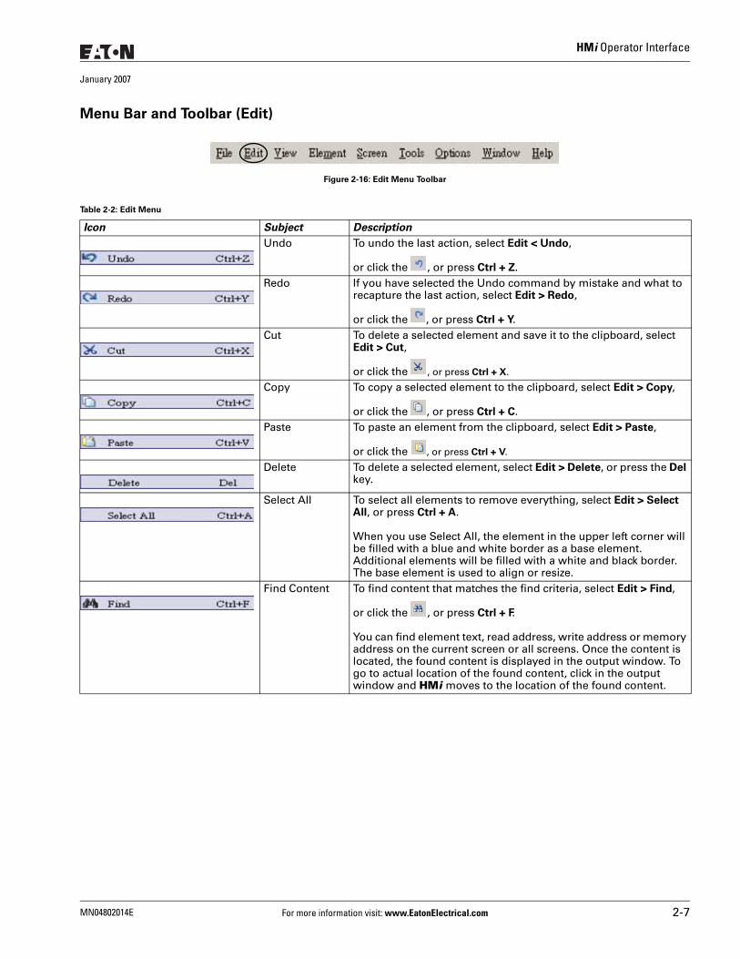
HMi Operator Interface
January 2007
Menu Bar and Toolbar (Edit)
Figure 2-16: Edit Menu Toolbar
Table 2-2: Edit Menu
Icon Subject Description
Undo To undo the last action, select Edit < Undo,
or click the , or press Ctrl + Z.Redo If you have selected the Undo command by mistake and what to
recapture the last action, select Edit > Redo,
or click the , or press Ctrl + Y.Cut To delete a selected element and save it to the clipboard, select
Edit > Cut,
or click the , or press Ctrl + X.
Copy To copy a selected element to the clipboard, select Edit > Copy,
or click the , or press Ctrl + C.Paste To paste an element from the clipboard, select Edit > Paste,
or click the , or press Ctrl + V.
Delete To delete a selected element, select Edit > Delete, or press the Del key.
Select All To select all elements to remove everything, select Edit > Select All, or press Ctrl + A.
When you use Select All, the element in the upper left corner will be filled with a blue and white border as a base element. Additional elements will be filled with a white and black border. The base element is used to align or resize.
Find Content To find content that matches the find criteria, select Edit > Find,
or click the , or press Ctrl + F.
You can find element text, read address, write address or memory address on the current screen or all screens. Once the content is located, the found content is displayed in the output window. To go to actual location of the found content, click in the output window and HMi moves to the location of the found content.
MN04802014E For more information visit: www.EatonElectrical.com 2-7
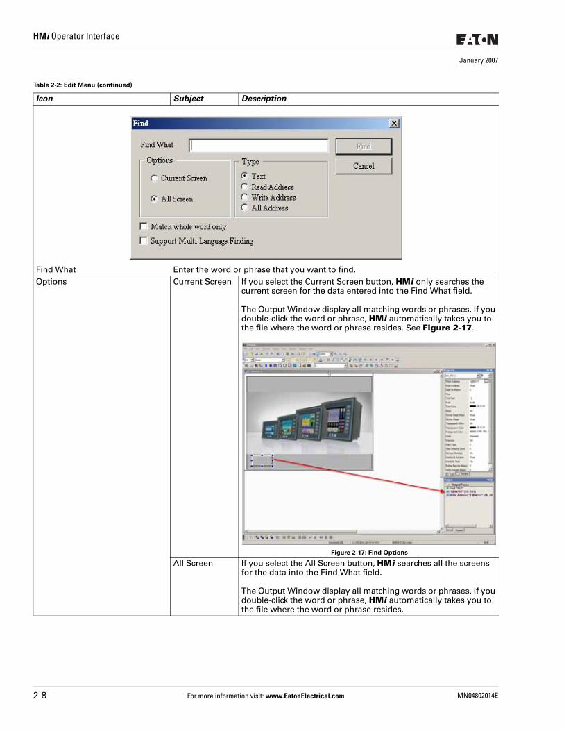
HMi Operator Interface
January 2007
Find What Enter the word or phrase that you want to find.Options Current Screen If you select the Current Screen button, HMi only searches the
current screen for the data entered into the Find What field.
The Output Window display all matching words or phrases. If you double-click the word or phrase, HMi automatically takes you to the file where the word or phrase resides. See Figure 2-17.
Figure 2-17: Find Options
All Screen If you select the All Screen button, HMi searches all the screens for the data into the Find What field.
The Output Window display all matching words or phrases. If you double-click the word or phrase, HMi automatically takes you to the file where the word or phrase resides.
Table 2-2: Edit Menu (continued)
Icon Subject Description
2-8 For more information visit: www.EatonElectrical.com MN04802014E
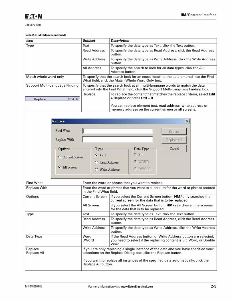
HMi Operator Interface
January 2007
Type Text To specify the data type as Text, click the Text button.Read Address To specify the data type as Read Address, click the Read Address
button.Write Address To specify the data type as Write Address, click the Write Address
button.All Address To specify the search to look for all data types, click the All
Address button.Match whole word only To specify that the search look for an exact match to the data entered into the Find
What field, click the Match Whole Word Only box.Support Multi-Language Finding To specify that the search look at all multi-language words to match the data
entered into the Find What field, click the Support Multi-Language Finding box.Replace To replace the content that matches the replace criteria, select Edit
> Replace or press Ctrl + R.
You can replace element text, read address, write address or memory address on the current screen or all screens.
Find What Enter the word or phrase that you want to replace.Replace With Enter the word or phrase that you want to substitute for the word or phrase entered
in the Find What field.Options Current Screen If you select the Current Screen button, HMi only searches the
current screen for the data that is to be replaced.All Screen If you select the All Screen button, HMi searches all the screens
for the data that is to be replaced.Type Text To specify the data type as Text, click the Text button.
Read Address To specify the data type as Read Address, click the Read Address button.
Write Address To specify the data type as Write Address, click the Write Address button.
Data Type WordDWord
If the Read Address button or Write Address button are selected, you need to select if the replacing content is Bit, Word, or Double Word.
ReplaceReplace All
If you are only replacing a single instance of the data and you have specified your selections on the Replace Dialog box, click the Replace button.
If you want to replace all instances of the specified data automatically, click the Replace All button.
Table 2-2: Edit Menu (continued)
Icon Subject Description
MN04802014E For more information visit: www.EatonElectrical.com 2-9
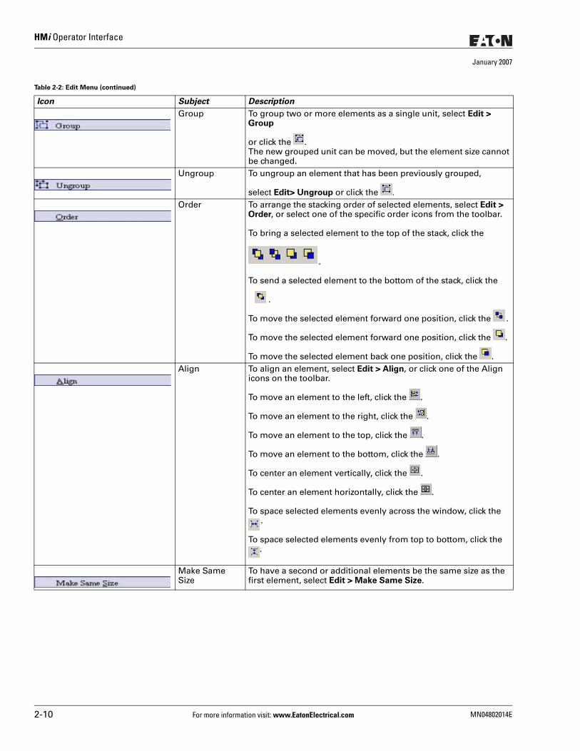
HMi Operator Interface
January 2007
Group To group two or more elements as a single unit, select Edit > Group
or click the . The new grouped unit can be moved, but the element size cannot be changed.
Ungroup To ungroup an element that has been previously grouped,
select Edit> Ungroup or click the .
Order To arrange the stacking order of selected elements, select Edit > Order, or select one of the specific order icons from the toolbar.
To bring a selected element to the top of the stack, click the
.
To send a selected element to the bottom of the stack, click the
.
To move the selected element forward one position, click the .
To move the selected element forward one position, click the .
To move the selected element back one position, click the .Align To align an element, select Edit > Align, or click one of the Align
icons on the toolbar.
To move an element to the left, click the .
To move an element to the right, click the .
To move an element to the top, click the .
To move an element to the bottom, click the .
To center an element vertically, click the .
To center an element horizontally, click the .
To space selected elements evenly across the window, click the .
To space selected elements evenly from top to bottom, click the .
Make Same Size
To have a second or additional elements be the same size as the first element, select Edit > Make Same Size.
Table 2-2: Edit Menu (continued)
Icon Subject Description
2-10 For more information visit: www.EatonElectrical.com MN04802014E
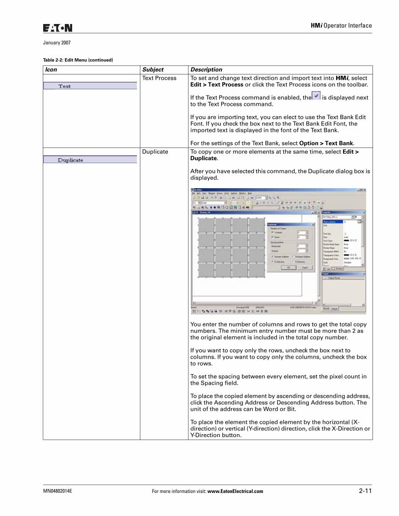
HMi Operator Interface
January 2007
Text Process To set and change text direction and import text into HMi, select Edit > Text Process or click the Text Process icons on the toolbar.
If the Text Process command is enabled, the is displayed next to the Text Process command.
If you are importing text, you can elect to use the Text Bank Edit Font. If you check the box next to the Text Bank Edit Font, the imported text is displayed in the font of the Text Bank.
For the settings of the Text Bank, select Option > Text Bank.Duplicate To copy one or more elements at the same time, select Edit >
Duplicate.
After you have selected this command, the Duplicate dialog box is displayed.
You enter the number of columns and rows to get the total copy numbers. The minimum entry number must be more than 2 as the original element is included in the total copy number.
If you want to copy only the rows, uncheck the box next to columns. If you want to copy only the columns, uncheck the box to rows.
To set the spacing between every element, set the pixel count in the Spacing field.
To place the copied element by ascending or descending address, click the Ascending Address or Descending Address button. The unit of the address can be Word or Bit.
To place the element the copied element by the horizontal (X-direction) or vertical (Y-direction) direction, click the X-Direction or Y-Direction button.
Table 2-2: Edit Menu (continued)
Icon Subject Description
MN04802014E For more information visit: www.EatonElectrical.com 2-11
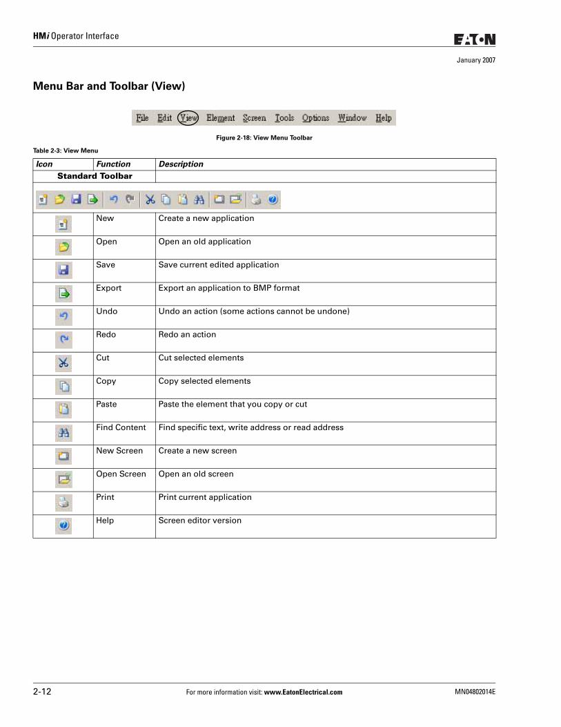
HMi Operator Interface
January 2007
Menu Bar and Toolbar (View)
Figure 2-18: View Menu Toolbar
Table 2-3: View Menu
Icon Function Description
Standard Toolbar
New Create a new application
Open Open an old application
Save Save current edited application
Export Export an application to BMP format
Undo Undo an action (some actions cannot be undone)
Redo Redo an action
Cut Cut selected elements
Copy Copy selected elements
Paste Paste the element that you copy or cut
Find Content Find specific text, write address or read address
New Screen Create a new screen
Open Screen Open an old screen
Print Print current application
Help Screen editor version
2-12 For more information visit: www.EatonElectrical.com MN04802014E
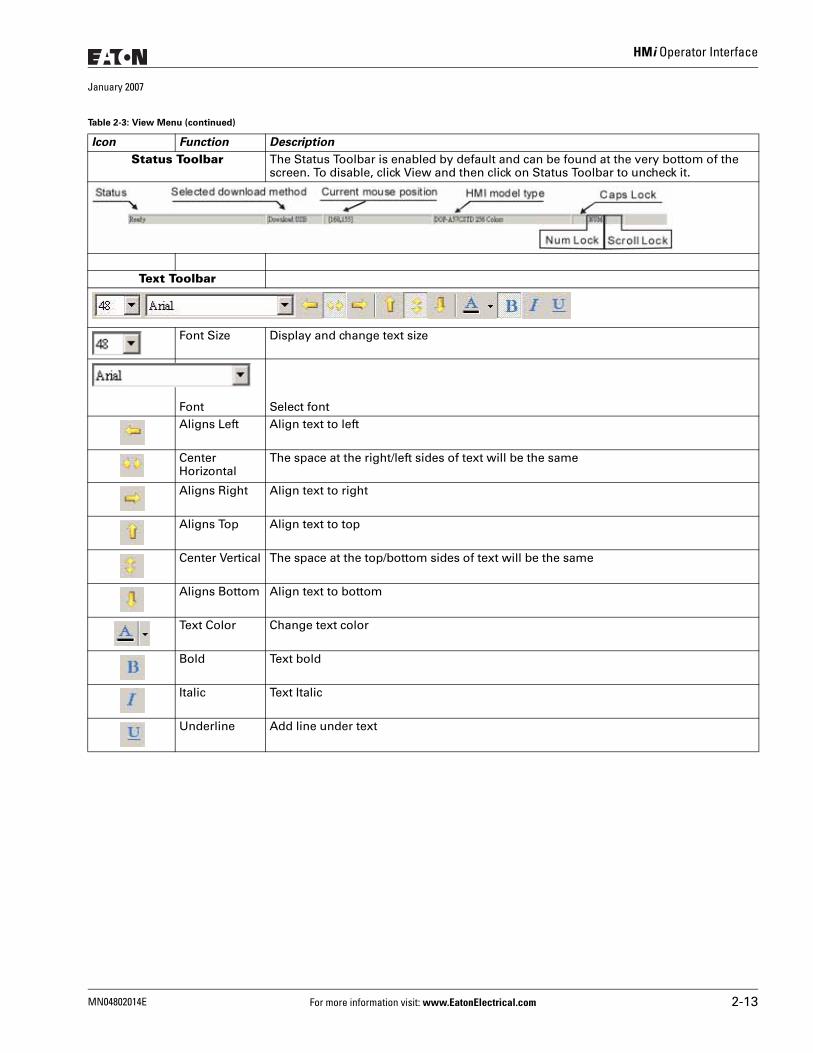
HMi Operator Interface
January 2007
Icon Function Description
Status Toolbar The Status Toolbar is enabled by default and can be found at the very bottom of the screen. To disable, click View and then click on Status Toolbar to uncheck it.
Text Toolbar
Font Size Display and change text size
Font Select fontAligns Left Align text to left
Center Horizontal
The space at the right/left sides of text will be the same
Aligns Right Align text to right
Aligns Top Align text to top
Center Vertical The space at the top/bottom sides of text will be the same
Aligns Bottom Align text to bottom
Text Color Change text color
Bold Text bold
Italic Text Italic
Underline Add line under text
Table 2-3: View Menu (continued)
MN04802014E For more information visit: www.EatonElectrical.com 2-13
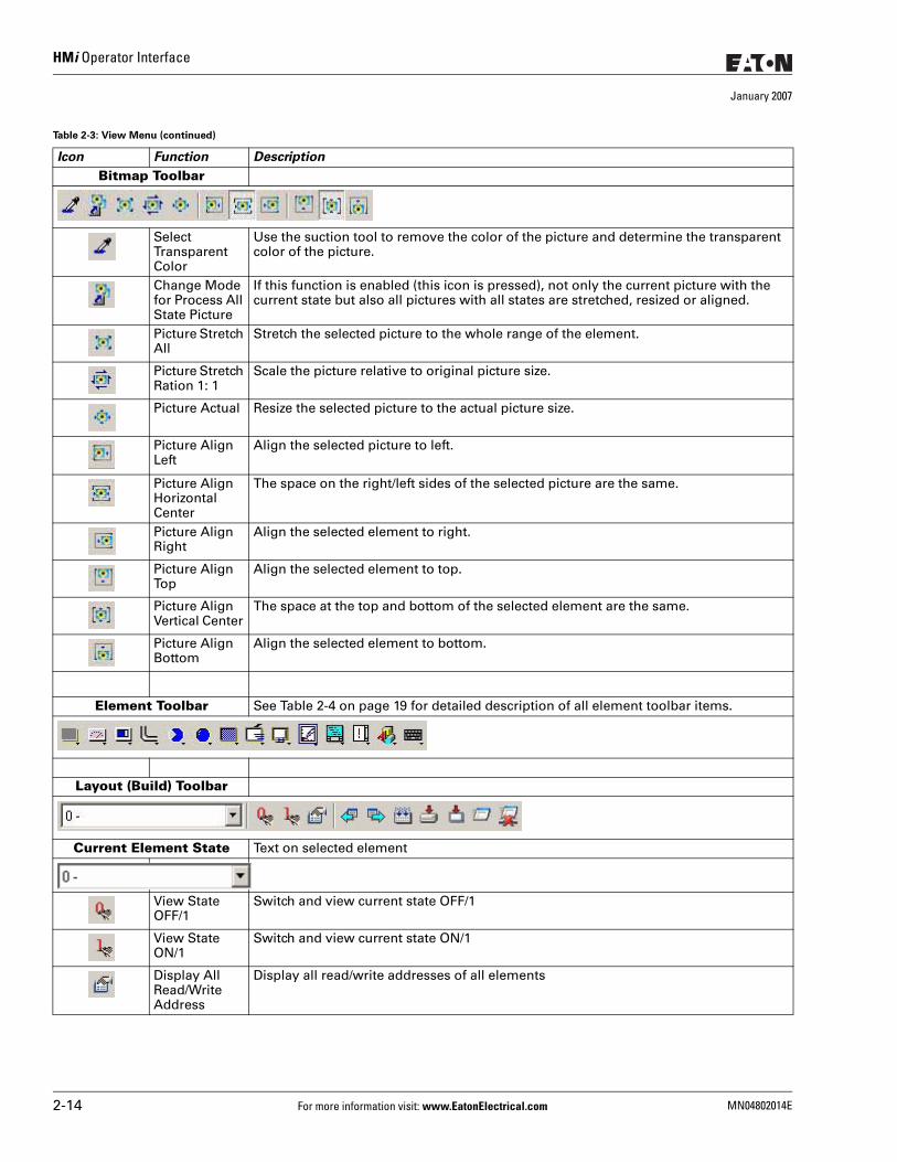
HMi Operator Interface
January 2007
Icon Function Description
Bitmap Toolbar
Select Transparent Color
Use the suction tool to remove the color of the picture and determine the transparent color of the picture.
Change Mode for Process All State Picture
If this function is enabled (this icon is pressed), not only the current picture with the current state but also all pictures with all states are stretched, resized or aligned.
Picture Stretch All
Stretch the selected picture to the whole range of the element.
Picture Stretch Ration 1: 1
Scale the picture relative to original picture size.
Picture Actual Resize the selected picture to the actual picture size.
Picture Align Left
Align the selected picture to left.
Picture Align Horizontal Center
The space on the right/left sides of the selected picture are the same.
Picture Align Right
Align the selected element to right.
Picture Align Top
Align the selected element to top.
Picture Align Vertical Center
The space at the top and bottom of the selected element are the same.
Picture Align Bottom
Align the selected element to bottom.
Element Toolbar See Table 2-4 on page 19 for detailed description of all element toolbar items.
Layout (Build) Toolbar
Current Element State Text on selected element
View State OFF/1
Switch and view current state OFF/1
View State ON/1
Switch and view current state ON/1
Display All Read/Write Address
Display all read/write addresses of all elements
Table 2-3: View Menu (continued)
2-14 For more information visit: www.EatonElectrical.com MN04802014E
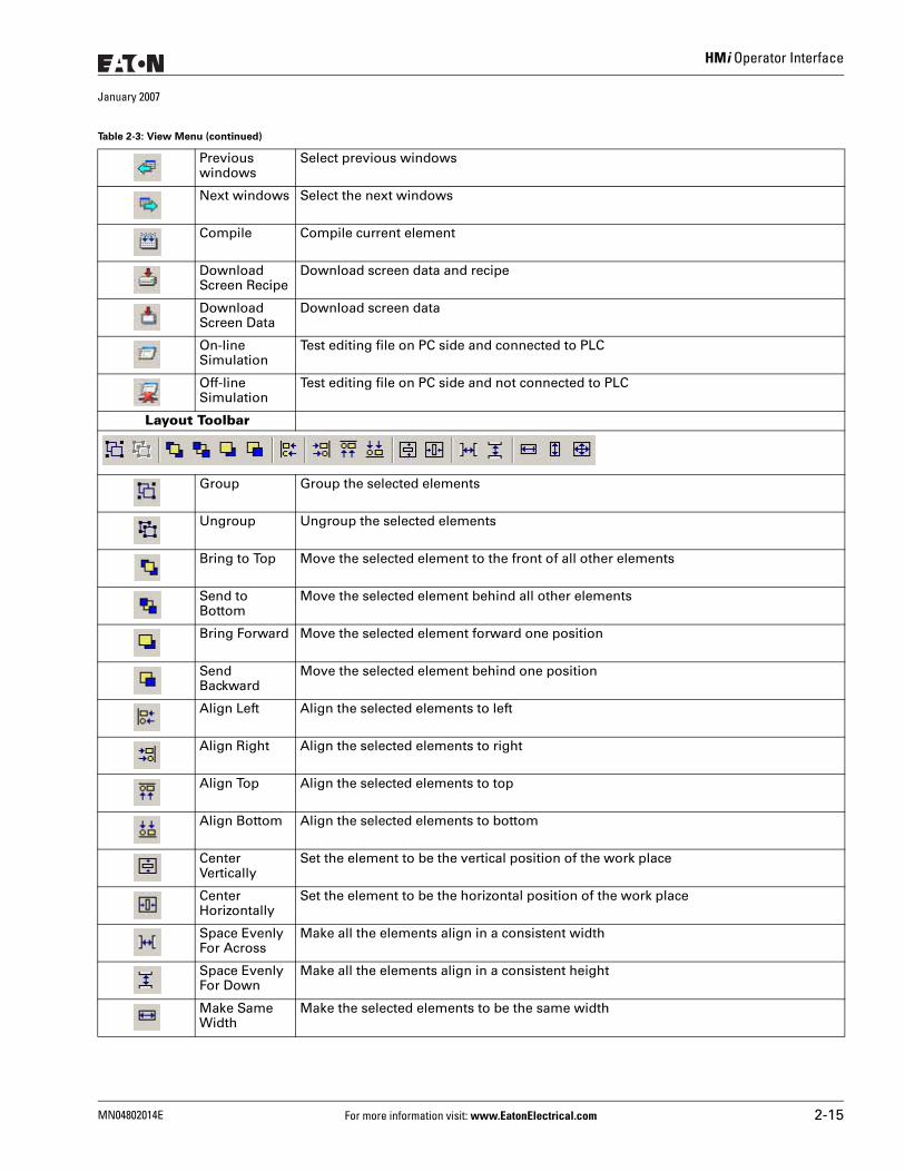
HMi Operator Interface
January 2007
Previous windows
Select previous windows
Next windows Select the next windows
Compile Compile current element
Download Screen Recipe
Download screen data and recipe
Download Screen Data
Download screen data
On-line Simulation
Test editing file on PC side and connected to PLC
Off-line Simulation
Test editing file on PC side and not connected to PLC
Layout Toolbar
Group Group the selected elements
Ungroup Ungroup the selected elements
Bring to Top Move the selected element to the front of all other elements
Send to Bottom
Move the selected element behind all other elements
Bring Forward Move the selected element forward one position
Send Backward
Move the selected element behind one position
Align Left Align the selected elements to left
Align Right Align the selected elements to right
Align Top Align the selected elements to top
Align Bottom Align the selected elements to bottom
Center Vertically
Set the element to be the vertical position of the work place
Center Horizontally
Set the element to be the horizontal position of the work place
Space Evenly For Across
Make all the elements align in a consistent width
Space Evenly For Down
Make all the elements align in a consistent height
Make Same Width
Make the selected elements to be the same width
Table 2-3: View Menu (continued)
MN04802014E For more information visit: www.EatonElectrical.com 2-15
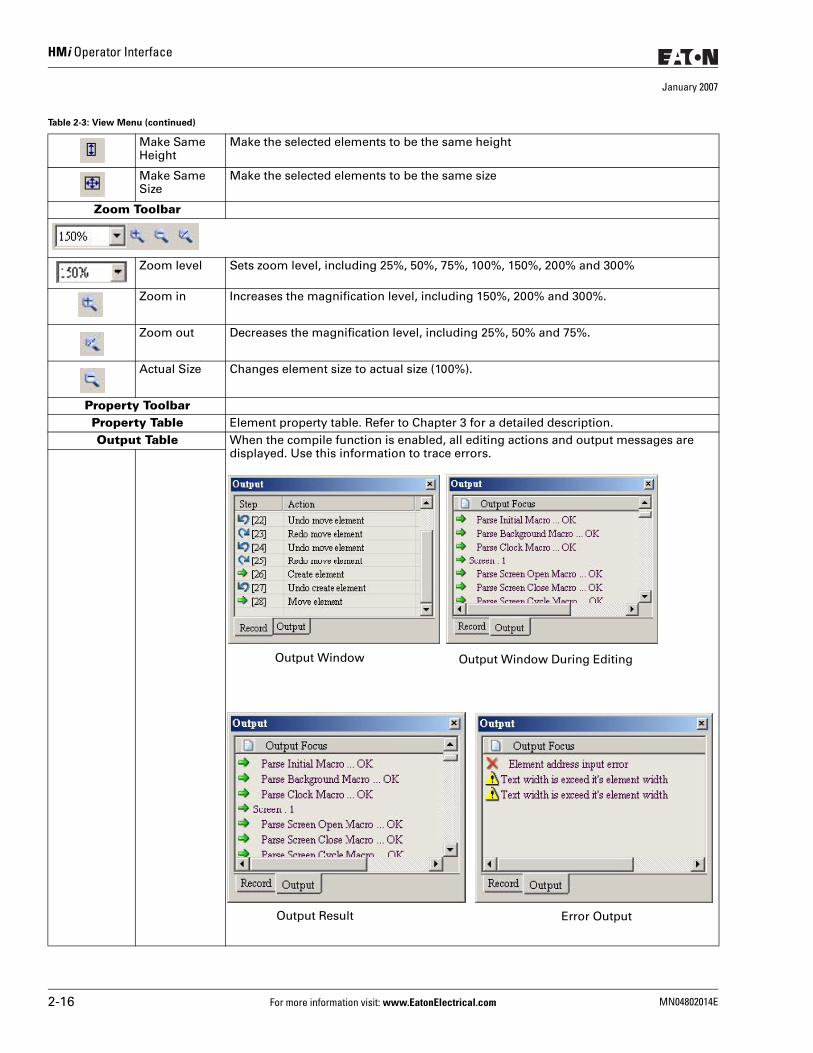
HMi Operator Interface
January 2007
Make Same Height
Make the selected elements to be the same height
Make Same Size
Make the selected elements to be the same size
Zoom Toolbar
Zoom level Sets zoom level, including 25%, 50%, 75%, 100%, 150%, 200% and 300%
Zoom in Increases the magnification level, including 150%, 200% and 300%.
Zoom out Decreases the magnification level, including 25%, 50% and 75%.
Actual Size Changes element size to actual size (100%).
Property ToolbarProperty Table Element property table. Refer to Chapter 3 for a detailed description.Output Table When the compile function is enabled, all editing actions and output messages are
displayed. Use this information to trace errors.
Table 2-3: View Menu (continued)
Output Window Output Window During Editing
Output Result Error Output
2-16 For more information visit: www.EatonElectrical.com MN04802014E
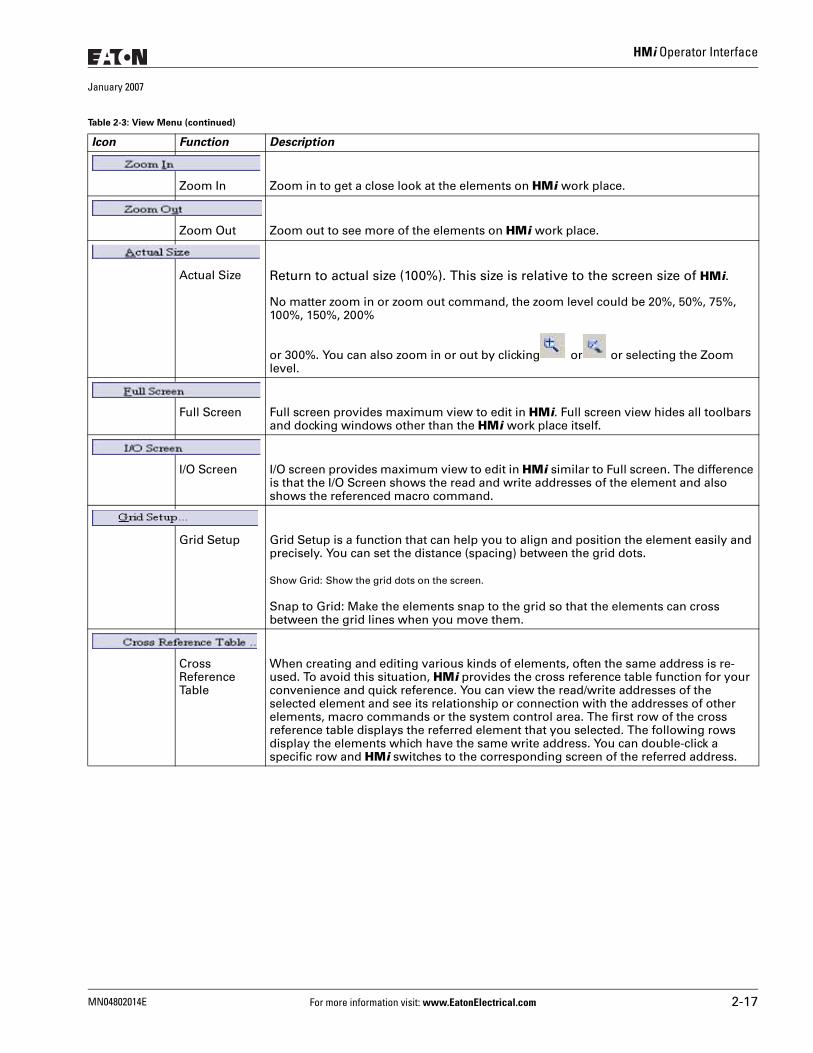
HMi Operator Interface
January 2007
Icon Function Description
Zoom In Zoom in to get a close look at the elements on HMi work place.
Zoom Out Zoom out to see more of the elements on HMi work place.
Actual Size Return to actual size (100%). This size is relative to the screen size of HMi.
No matter zoom in or zoom out command, the zoom level could be 20%, 50%, 75%, 100%, 150%, 200%
or 300%. You can also zoom in or out by clicking or or selecting the Zoom level.
Full Screen Full screen provides maximum view to edit in HMi. Full screen view hides all toolbars and docking windows other than the HMi work place itself.
I/O Screen I/O screen provides maximum view to edit in HMi similar to Full screen. The difference is that the I/O Screen shows the read and write addresses of the element and also shows the referenced macro command.
Grid Setup Grid Setup is a function that can help you to align and position the element easily and precisely. You can set the distance (spacing) between the grid dots.
Show Grid: Show the grid dots on the screen.
Snap to Grid: Make the elements snap to the grid so that the elements can cross between the grid lines when you move them.
Cross Reference Table
When creating and editing various kinds of elements, often the same address is re-used. To avoid this situation, HMi provides the cross reference table function for your convenience and quick reference. You can view the read/write addresses of the selected element and see its relationship or connection with the addresses of other elements, macro commands or the system control area. The first row of the cross reference table displays the referred element that you selected. The following rows display the elements which have the same write address. You can double-click a specific row and HMi switches to the corresponding screen of the referred address.
Table 2-3: View Menu (continued)
MN04802014E For more information visit: www.EatonElectrical.com 2-17
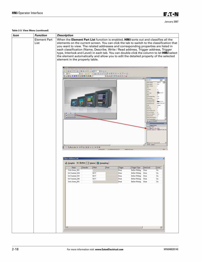
HMi Operator Interface
January 2007
Icon Function Description
Element Part List
When the Element Part List function is enabled, HMi sorts out and classifies all the elements on the current screen. You can click the tab to switch to the classification that you want to view. The related addresses and corresponding properties are listed in each classification (Name, Describe, Write / Read address, Trigger address, Trigger type, Interlock and Level) in each tab. You can double-click the column to let HMi select the element automatically and allow you to edit the detailed property of the selected element in the property table.
Table 2-3: View Menu (continued)
2-18 For more information visit: www.EatonElectrical.com MN04802014E
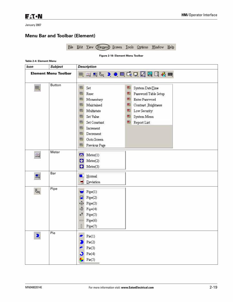
HMi Operator Interface
January 2007
Menu Bar and Toolbar (Element)
Figure 2-19: Element Menu Toolbar
Table 2-4: Element Menu
Icon Subject Description
Element Menu Toolbar
Button
Meter
Bar
Pipe
Pie
MN04802014E For more information visit: www.EatonElectrical.com 2-19
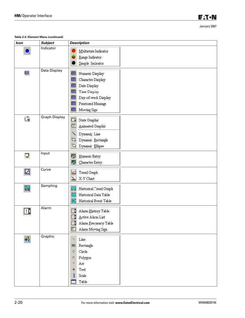
HMi Operator Interface
January 2007
Indicator
Data Display
Graph Display
Input
Curve
Sampling
Alarm
Graphic
Table 2-4: Element Menu (continued)
Icon Subject Description
2-20 For more information visit: www.EatonElectrical.com MN04802014E
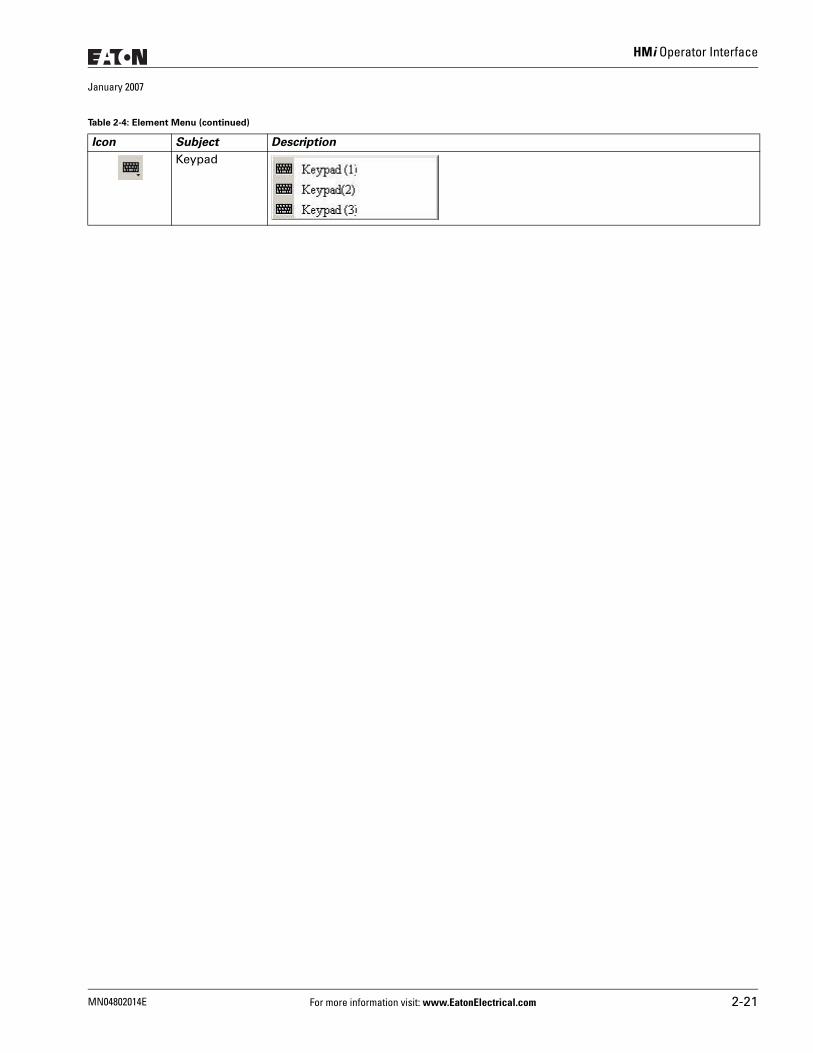
HMi Operator Interface
January 2007
Keypad
Table 2-4: Element Menu (continued)
Icon Subject Description
MN04802014E For more information visit: www.EatonElectrical.com 2-21
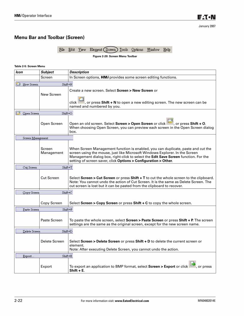
HMi Operator Interface
January 2007
Menu Bar and Toolbar (Screen)
Figure 2-20: Screen Menu Toolbar
Table 2-5: Screen Menu
Icon Subject Description
Screen In Screen options, HMi provides some screen editing functions.
New ScreenCreate a new screen. Select Screen > New Screen or
click , or press Shift + N to open a new editing screen. The new screen can be named and numbered by you.
Open Screen Open an old screen. Select Screen > Open Screen or click , or press Shift + O. When choosing Open Screen, you can preview each screen in the Open Screen dialog box.
Screen Management
When Screen Management function is enabled, you can duplicate, paste and cut the screen using the mouse, just like Microsoft Windows Explorer. In the Screen Management dialog box, right-click to select the Edit Save Screen function. For the setting of screen saver, click Options > Configuration > Other.
Cut Screen Select Screen > Cut Screen or press Shift + T to cut the whole screen to the clipboard.Note: You cannot undo the action of Cut Screen. It is the same as Delete Screen. The cut screen is lost but it can be pasted from the clipboard to recover.
Copy Screen Select Screen > Copy Screen or press Shift + C to copy the whole screen.
Paste Screen To paste the whole screen, select Screen > Paste Screen or press Shift + P. The screen settings are the same as the original screen, except for the new screen name.
Delete Screen Select Screen > Delete Screen or press Shift + D to delete the current screen or element.Note: After executing Delete Screen, you cannot undo the action.
Export To export an application to BMP format, select Screen > Export or click , or press Shift + E.
2-22 For more information visit: www.EatonElectrical.com MN04802014E
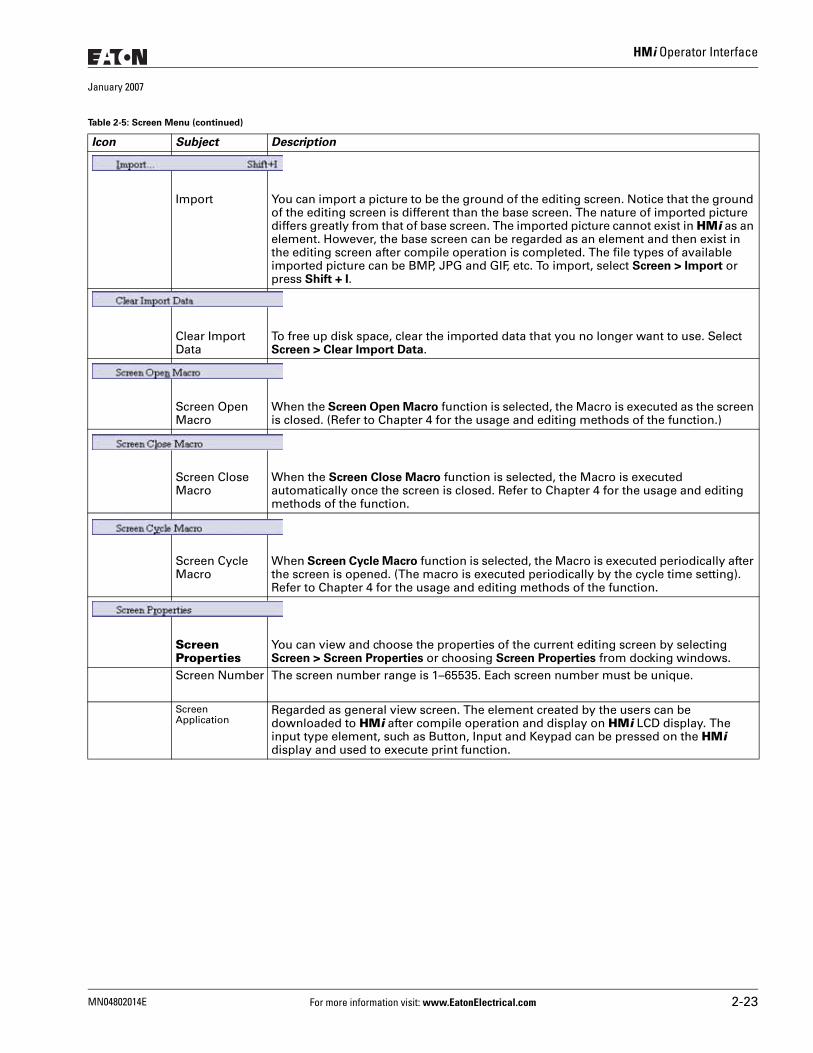
HMi Operator Interface
January 2007
Import You can import a picture to be the ground of the editing screen. Notice that the ground of the editing screen is different than the base screen. The nature of imported picture differs greatly from that of base screen. The imported picture cannot exist in HMi as an element. However, the base screen can be regarded as an element and then exist in the editing screen after compile operation is completed. The file types of available imported picture can be BMP, JPG and GIF, etc. To import, select Screen > Import or press Shift + I.
Clear Import Data
To free up disk space, clear the imported data that you no longer want to use. Select Screen > Clear Import Data.
Screen Open Macro
When the Screen Open Macro function is selected, the Macro is executed as the screen is closed. (Refer to Chapter 4 for the usage and editing methods of the function.)
Screen Close Macro
When the Screen Close Macro function is selected, the Macro is executed automatically once the screen is closed. Refer to Chapter 4 for the usage and editing methods of the function.
Screen Cycle Macro
When Screen Cycle Macro function is selected, the Macro is executed periodically after the screen is opened. (The macro is executed periodically by the cycle time setting). Refer to Chapter 4 for the usage and editing methods of the function.
Screen Properties
You can view and choose the properties of the current editing screen by selecting Screen > Screen Properties or choosing Screen Properties from docking windows.
Screen Number The screen number range is 1–65535. Each screen number must be unique.
ScreenApplication
Regarded as general view screen. The element created by the users can be downloaded to HMi after compile operation and display on HMi LCD display. The input type element, such as Button, Input and Keypad can be pressed on the HMi display and used to execute print function.
Table 2-5: Screen Menu (continued)
Icon Subject Description
MN04802014E For more information visit: www.EatonElectrical.com 2-23
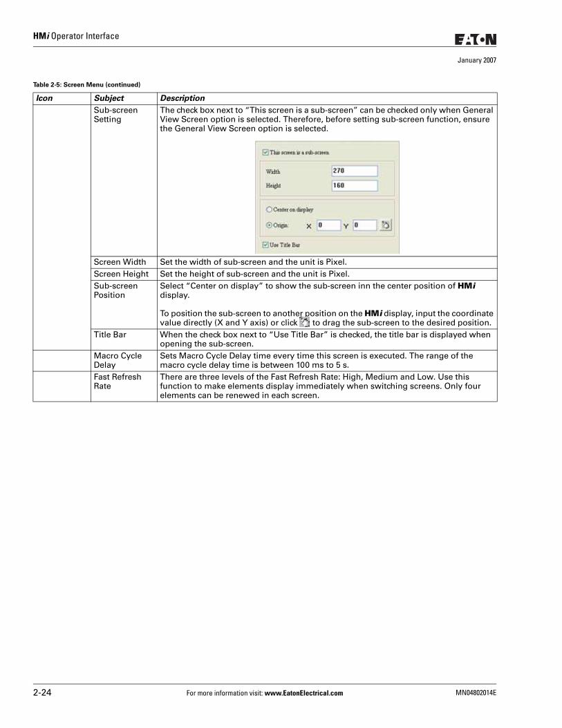
HMi Operator Interface
January 2007
Sub-screen Setting
The check box next to “This screen is a sub-screen” can be checked only when General View Screen option is selected. Therefore, before setting sub-screen function, ensure the General View Screen option is selected.
Screen Width Set the width of sub-screen and the unit is Pixel.Screen Height Set the height of sub-screen and the unit is Pixel.Sub-screen Position
Select “Center on display” to show the sub-screen inn the center position of HMi display.
To position the sub-screen to another position on the HMi display, input the coordinate value directly (X and Y axis) or click to drag the sub-screen to the desired position.
Title Bar When the check box next to “Use Title Bar” is checked, the title bar is displayed when opening the sub-screen.
Macro Cycle Delay
Sets Macro Cycle Delay time every time this screen is executed. The range of the macro cycle delay time is between 100 ms to 5 s.
Fast Refresh Rate
There are three levels of the Fast Refresh Rate: High, Medium and Low. Use this function to make elements display immediately when switching screens. Only four elements can be renewed in each screen.
Table 2-5: Screen Menu (continued)
Icon Subject Description
2-24 For more information visit: www.EatonElectrical.com MN04802014E
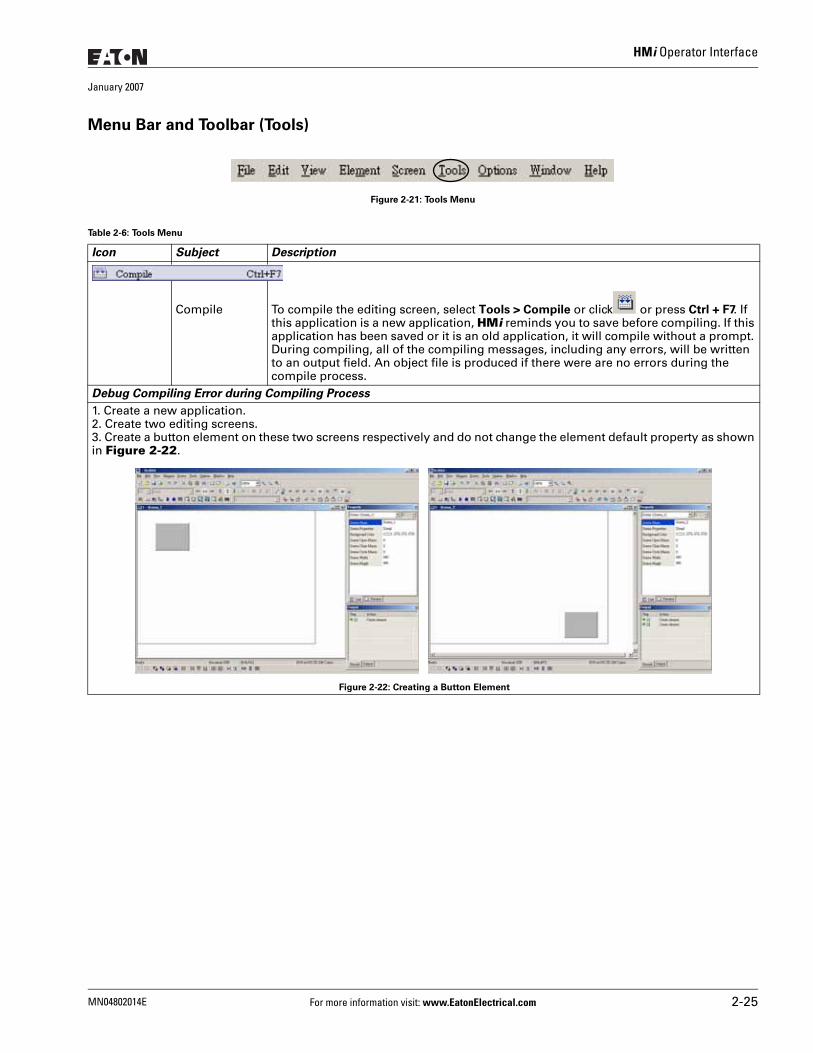
HMi Operator Interface
January 2007
Menu Bar and Toolbar (Tools)
Figure 2-21: Tools Menu
Table 2-6: Tools Menu
Icon Subject Description
Compile To compile the editing screen, select Tools > Compile or click or press Ctrl + F7. If this application is a new application, HMi reminds you to save before compiling. If this application has been saved or it is an old application, it will compile without a prompt. During compiling, all of the compiling messages, including any errors, will be written to an output field. An object file is produced if there were are no errors during the compile process.
Debug Compiling Error during Compiling Process
1. Create a new application.2. Create two editing screens.3. Create a button element on these two screens respectively and do not change the element default property as shown in Figure 2-22.
Figure 2-22: Creating a Button Element
MN04802014E For more information visit: www.EatonElectrical.com 2-25
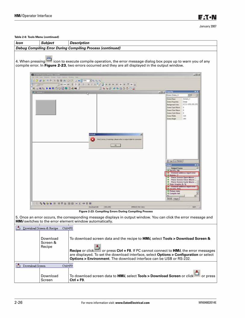
HMi Operator Interface
January 2007
Debug Compiling Error During Compiling Process (continued)
4. When pressing icon to execute compile operation, the error message dialog box pops up to warn you of any compile error. In Figure 2-23, two errors occurred and they are all displayed in the output window.
Figure 2-23: Compiling Errors During Compiling Process
5. Once an error occurs, the corresponding message displays in output window. You can click the error message and HMi switches to the error element window automatically.
Download Screen & Recipe
To download screen data and the recipe to HMi, select Tools > Download Screen &
Recipe or click or press Ctrl + F8. If PC cannot connect to HMi, the error messages are displayed. To set the download interface, select Options > Configuration or select Options > Environment. The download interface can be USB or RS-232.
Download Screen
To download screen data to HMi, select Tools > Download Screen or click or press Ctrl + F9.
Table 2-6: Tools Menu (continued)
Icon Subject Description
2-26 For more information visit: www.EatonElectrical.com MN04802014E
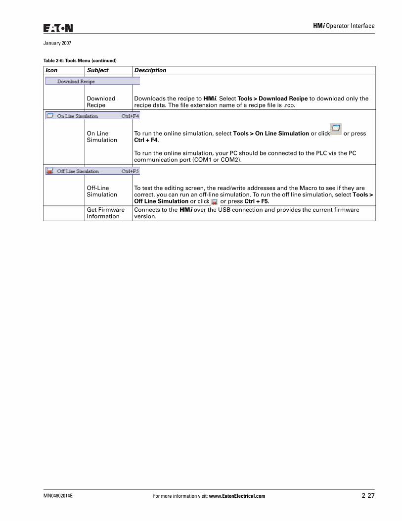
HMi Operator Interface
January 2007
Download Recipe
Downloads the recipe to HMi. Select Tools > Download Recipe to download only the recipe data. The file extension name of a recipe file is .rcp.
On Line Simulation
To run the online simulation, select Tools > On Line Simulation or click or press Ctrl + F4.
To run the online simulation, your PC should be connected to the PLC via the PC communication port (COM1 or COM2).
Off-Line Simulation
To test the editing screen, the read/write addresses and the Macro to see if they are correct, you can run an off-line simulation. To run the off line simulation, select Tools > Off Line Simulation or click or press Ctrl + F5.
Get Firmware Information
Connects to the HMi over the USB connection and provides the current firmware version.
Table 2-6: Tools Menu (continued)
Icon Subject Description
MN04802014E For more information visit: www.EatonElectrical.com 2-27
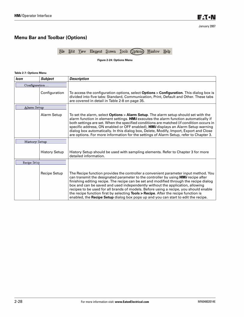
HMi Operator Interface
January 2007
Menu Bar and Toolbar (Options)
Figure 2-24: Options Menu
Table 2-7: Options Menu
Icon Subject Description
Configuration To access the configuration options, select Options > Configuration. This dialog box is divided into five tabs: Standard, Communication, Print, Default and Other. These tabs are covered in detail in Table 2-8 on page 35.
Alarm Setup To set the alarm, select Options > Alarm Setup. The alarm setup should set with the alarm function in element settings. HMi executes the alarm function automatically if both settings are set. When the specified conditions are matched (if condition occurs in specific address, ON enabled or OFF enabled), HMi displays an Alarm Setup warning dialog box automatically. In this dialog box, Delete, Modify, Import, Export and Close are options. For more information for the settings of Alarm Setup, refer to Chapter 3.
History Setup History Setup should be used with sampling elements. Refer to Chapter 3 for more detailed information.
Recipe Setup The Recipe function provides the controller a convenient parameter input method. You can transmit the designated parameter to the controller by using HMi recipe after finishing editing recipe. The recipe can be set and modified through the recipe dialog box and can be saved and used independently without the application, allowing recipes to be used for all brands of models. Before using a recipe, you should enable the recipe function first by selecting Tools > Recipe. After the recipe function is enabled, the Recipe Setup dialog box pops up and you can start to edit the recipe.
2-28 For more information visit: www.EatonElectrical.com MN04802014E
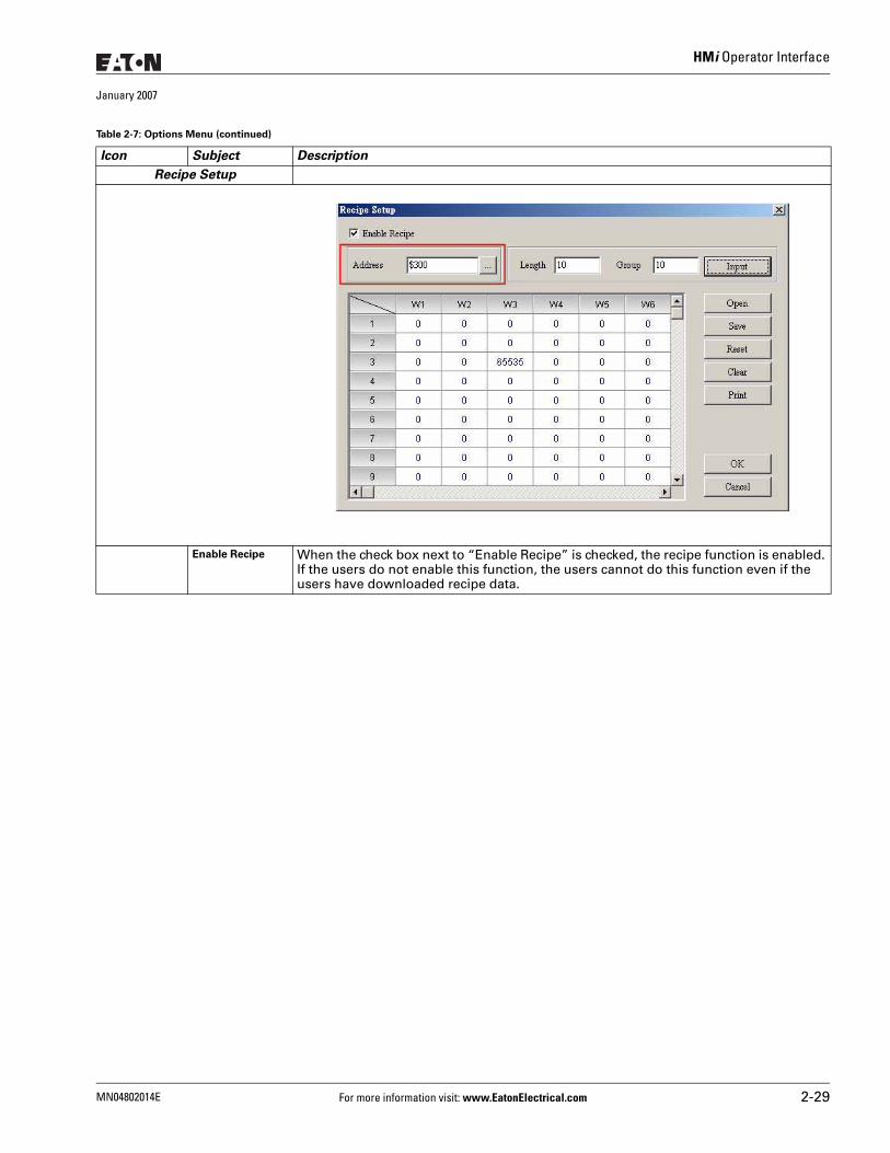
HMi Operator Interface
January 2007
Recipe Setup
Enable Recipe When the check box next to “Enable Recipe” is checked, the recipe function is enabled. If the users do not enable this function, the users cannot do this function even if the users have downloaded recipe data.
Table 2-7: Options Menu (continued)
Icon Subject Description
MN04802014E For more information visit: www.EatonElectrical.com 2-29
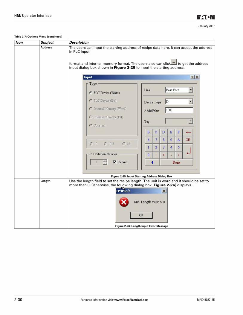
HMi Operator Interface
January 2007
Address The users can input the starting address of recipe data here. It can accept the address in PLC input
format and internal memory format. The users also can click to get the address input dialog box shown in Figure 2-25 to input the starting address.
Figure 2-25: Input Starting Address Dialog Box
Length Use the length field to set the recipe length. The unit is word and it should be set to more than 0. Otherwise, the following dialog box (Figure 2-26) displays.
Figure 2-26: Length Input Error Message
Table 2-7: Options Menu (continued)
Icon Subject Description
2-30 For more information visit: www.EatonElectrical.com MN04802014E
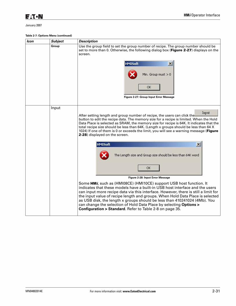
HMi Operator Interface
January 2007
Group Use the group field to set the group number of recipe. The group number should be set to more than 0. Otherwise, the following dialog box (Figure 2-27) displays on the screen.
Figure 2-27: Group Input Error Message
Input
After setting length and group number of recipe, the users can click the button to edit the recipe data. The memory size for a recipe is limited. When the Hold Data Place is selected as SRAM, the memory size for recipe is 64K. It indicates that the total recipe size should be less than 64K. (Length x groups should be less than 64 X 1024) If one of them is 0 or exceeds the limit, you will see a warning message (Figure 2-28) displayed on the screen.
Figure 2-28: Input Error Message
Some HMi, such as (HMI08CE) (HMI10CE) support USB host function. It indicates that these models have a built-in USB host interface and the users can input more recipe data via this interface. However, there is still a limit for the input value of recipe length and groups. When Hold Data Place is selected as USB disk, the length x groups should be less than 410241024 (4Mb). You can change the selection of Hold Data Place by selecting Options > Configuration > Standard. Refer to Table 2-8 on page 35.
Table 2-7: Options Menu (continued)
Icon Subject Description
MN04802014E For more information visit: www.EatonElectrical.com 2-31
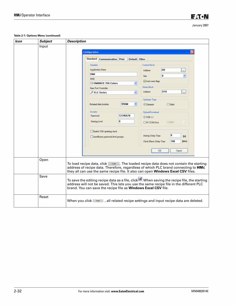
HMi Operator Interface
January 2007
Input
OpenTo load recipe data, click . The loaded recipe data does not contain the starting address of recipe data. Therefore, regardless of which PLC brand connecting to HMi, they all can use the same recipe file. It also can open Windows Excel CSV files.
SaveTo save the editing recipe data as a file, click When saving the recipe file, the starting address will not be saved. This lets you use the same recipe file in the different PLC brand. You can save the recipe file as Windows Excel CSV file.
ResetWhen you click , all related recipe settings and input recipe data are deleted.
Table 2-7: Options Menu (continued)
Icon Subject Description
2-32 For more information visit: www.EatonElectrical.com MN04802014E
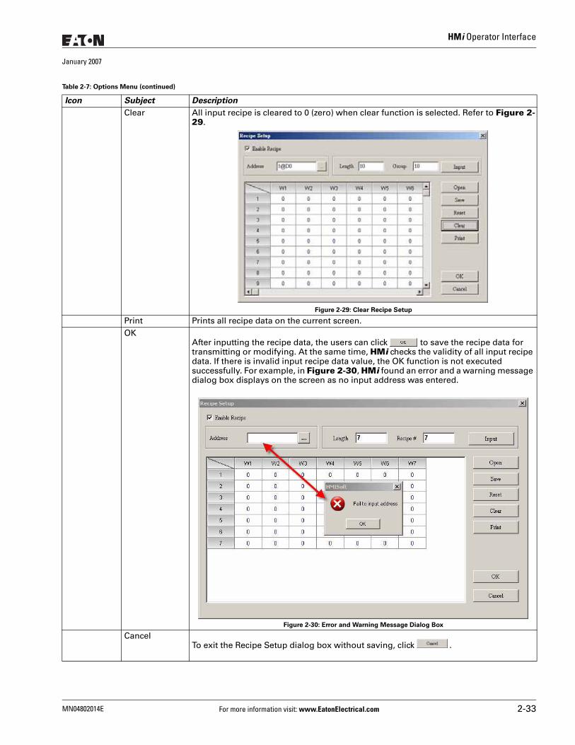
HMi Operator Interface
January 2007
Clear All input recipe is cleared to 0 (zero) when clear function is selected. Refer to Figure 2-29.
Figure 2-29: Clear Recipe Setup
Print Prints all recipe data on the current screen.OK
After inputting the recipe data, the users can click to save the recipe data for transmitting or modifying. At the same time, HMi checks the validity of all input recipe data. If there is invalid input recipe data value, the OK function is not executed successfully. For example, in Figure 2-30, HMi found an error and a warning message dialog box displays on the screen as no input address was entered.
Figure 2-30: Error and Warning Message Dialog Box
CancelTo exit the Recipe Setup dialog box without saving, click .
Table 2-7: Options Menu (continued)
Icon Subject Description
MN04802014E For more information visit: www.EatonElectrical.com 2-33
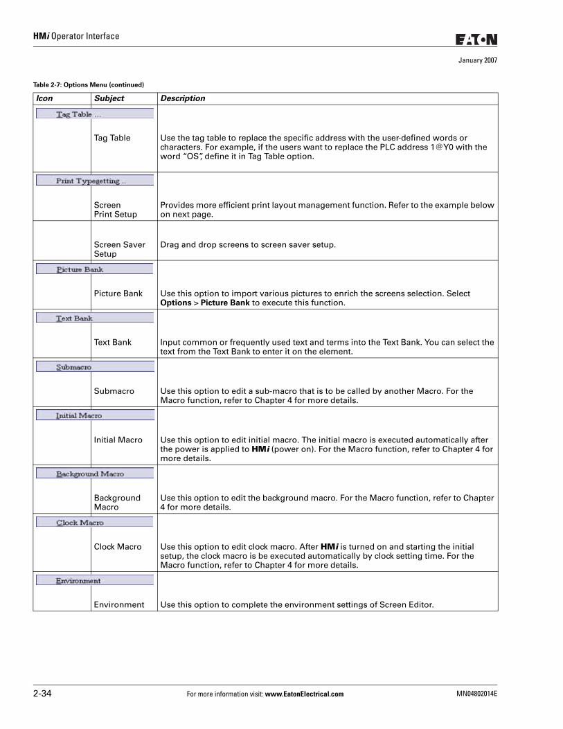
HMi Operator Interface
January 2007
Tag Table Use the tag table to replace the specific address with the user-defined words or characters. For example, if the users want to replace the PLC address 1@Y0 with the word “OS”, define it in Tag Table option.
ScreenPrint Setup
Provides more efficient print layout management function. Refer to the example below on next page.
Screen Saver Setup
Drag and drop screens to screen saver setup.
Picture Bank Use this option to import various pictures to enrich the screens selection. Select Options > Picture Bank to execute this function.
Text Bank Input common or frequently used text and terms into the Text Bank. You can select the text from the Text Bank to enter it on the element.
Submacro Use this option to edit a sub-macro that is to be called by another Macro. For the Macro function, refer to Chapter 4 for more details.
Initial Macro Use this option to edit initial macro. The initial macro is executed automatically after the power is applied to HMi (power on). For the Macro function, refer to Chapter 4 for more details.
Background Macro
Use this option to edit the background macro. For the Macro function, refer to Chapter 4 for more details.
Clock Macro Use this option to edit clock macro. After HMi is turned on and starting the initial setup, the clock macro is be executed automatically by clock setting time. For the Macro function, refer to Chapter 4 for more details.
Environment Use this option to complete the environment settings of Screen Editor.
Table 2-7: Options Menu (continued)
Icon Subject Description
2-34 For more information visit: www.EatonElectrical.com MN04802014E
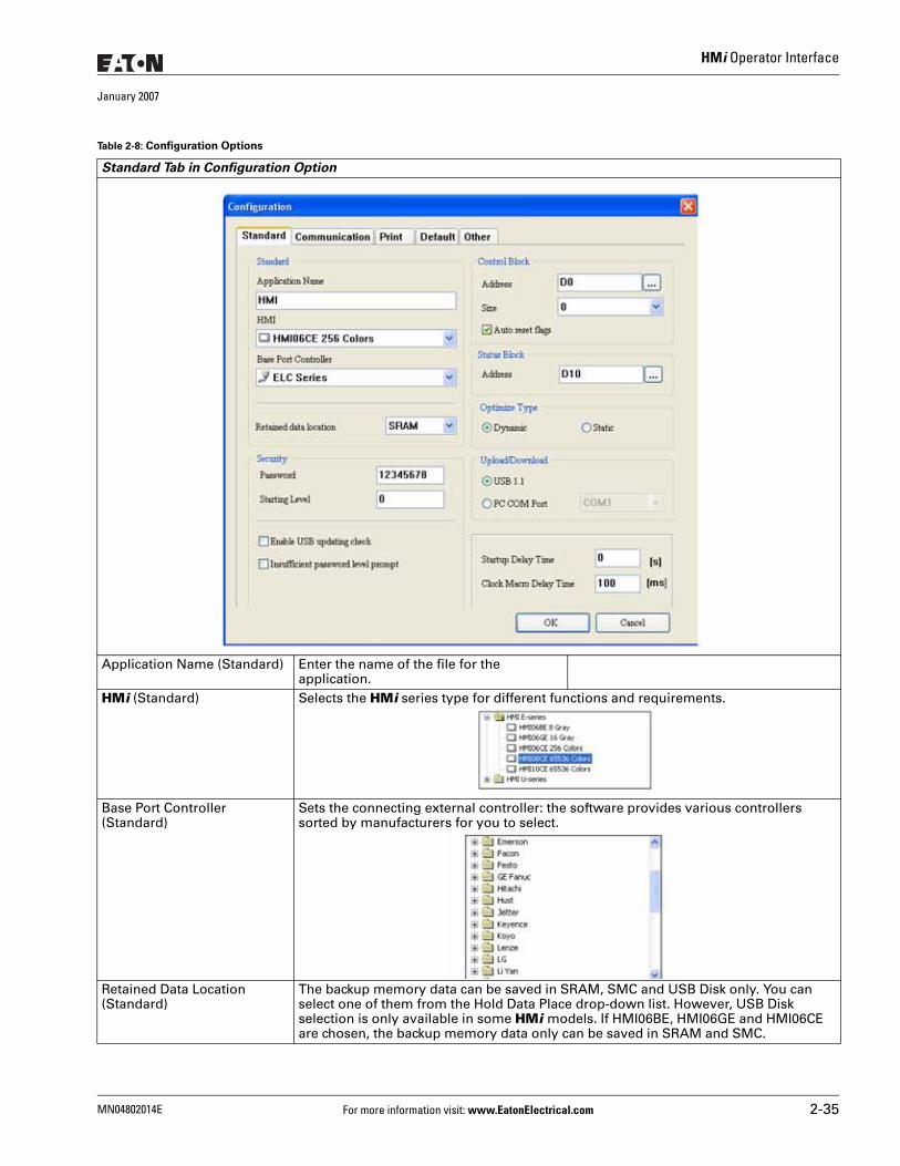
HMi Operator Interface
January 2007
Table 2-8: Configuration Options
Standard Tab in Configuration Option
Application Name (Standard) Enter the name of the file for the application.
HMi (Standard) Selects the HMi series type for different functions and requirements.
Base Port Controller (Standard)
Sets the connecting external controller: the software provides various controllers sorted by manufacturers for you to select.
Retained Data Location (Standard)
The backup memory data can be saved in SRAM, SMC and USB Disk only. You can select one of them from the Hold Data Place drop-down list. However, USB Disk selection is only available in some HMi models. If HMI06BE, HMI06GE and HMI06CE are chosen, the backup memory data only can be saved in SRAM and SMC.
MN04802014E For more information visit: www.EatonElectrical.com 2-35
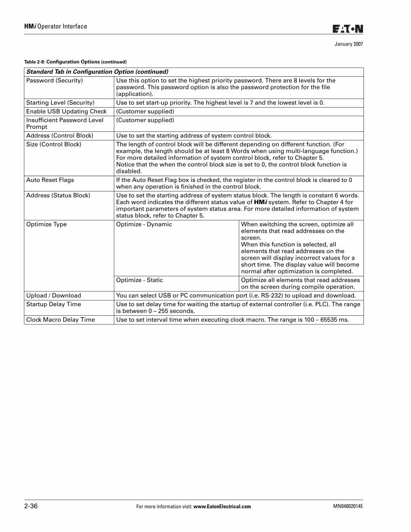
HMi Operator Interface
January 2007
Standard Tab in Configuration Option (continued)
Password (Security) Use this option to set the highest priority password. There are 8 levels for the password. This password option is also the password protection for the file (application).
Starting Level (Security) Use to set start-up priority. The highest level is 7 and the lowest level is 0.Enable USB Updating Check (Customer supplied)Insufficient Password Level Prompt
(Customer supplied)
Address (Control Block) Use to set the starting address of system control block.Size (Control Block) The length of control block will be different depending on different function. (For
example, the length should be at least 8 Words when using multi-language function.) For more detailed information of system control block, refer to Chapter 5. Notice that the when the control block size is set to 0, the control block function is disabled.
Auto Reset Flags If the Auto Reset Flag box is checked, the register in the control block is cleared to 0 when any operation is finished in the control block.
Address (Status Block) Use to set the starting address of system status block. The length is constant 6 words. Each word indicates the different status value of HMi system. Refer to Chapter 4 for important parameters of system status area. For more detailed information of system status block, refer to Chapter 5.
Optimize Type Optimize - Dynamic When switching the screen, optimize all elements that read addresses on the screen.When this function is selected, all elements that read addresses on the screen will display incorrect values for a short time. The display value will become normal after optimization is completed.
Optimize - Static Optimize all elements that read addresses on the screen during compile operation.
Upload / Download You can select USB or PC communication port (i.e. RS-232) to upload and download.Startup Delay Time Use to set delay time for waiting the startup of external controller (i.e. PLC). The range
is between 0 – 255 seconds. Clock Macro Delay Time Use to set interval time when executing clock macro. The range is 100 – 65535 ms.
Table 2-8: Configuration Options (continued)
2-36 For more information visit: www.EatonElectrical.com MN04802014E
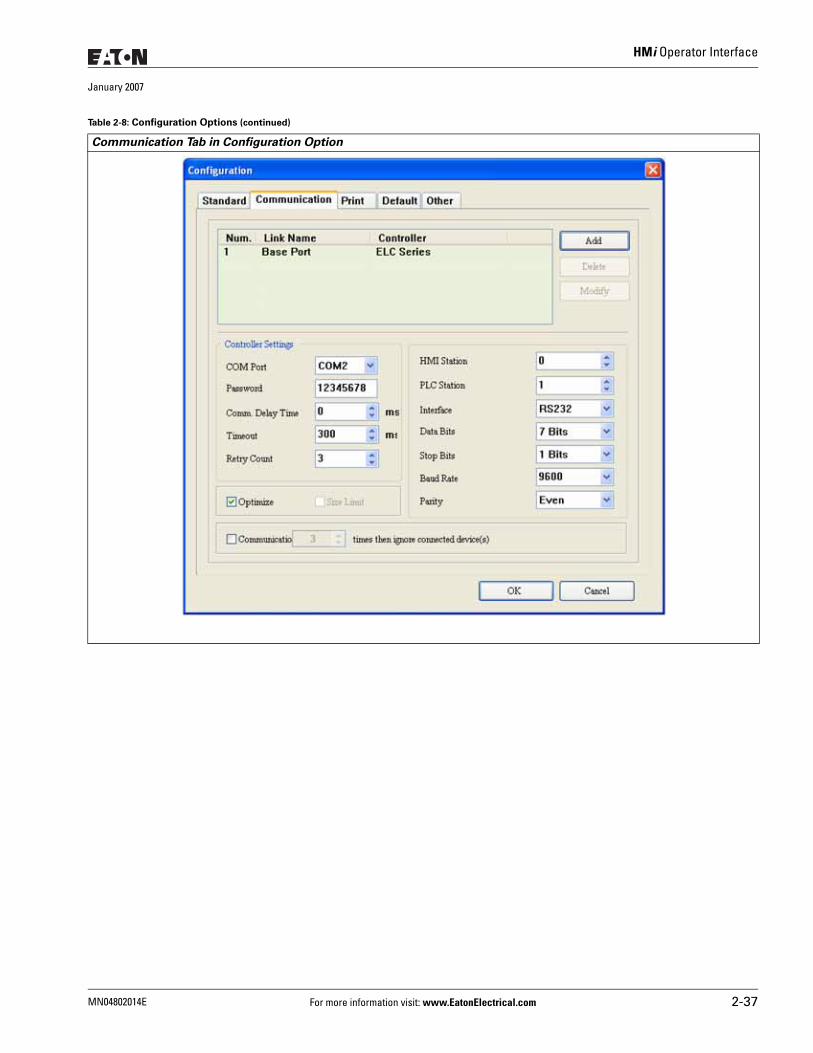
HMi Operator Interface
January 2007
Communication Tab in Configuration Option
Table 2-8: Configuration Options (continued)
MN04802014E For more information visit: www.EatonElectrical.com 2-37
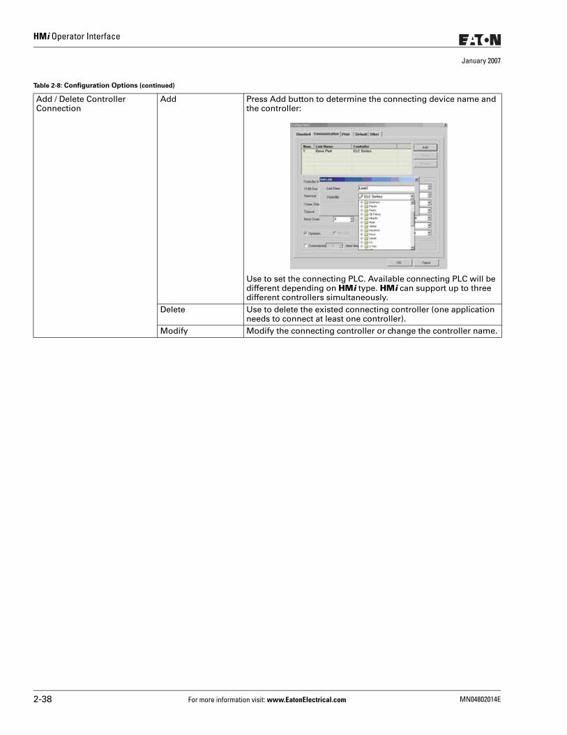
HMi Operator Interface
January 2007
Add / Delete Controller Connection
Add Press Add button to determine the connecting device name and the controller:
Use to set the connecting PLC. Available connecting PLC will be different depending on HMi type. HMi can support up to three different controllers simultaneously.
Delete Use to delete the existed connecting controller (one application needs to connect at least one controller).
Modify Modify the connecting controller or change the controller name.
Table 2-8: Configuration Options (continued)
2-38 For more information visit: www.EatonElectrical.com MN04802014E
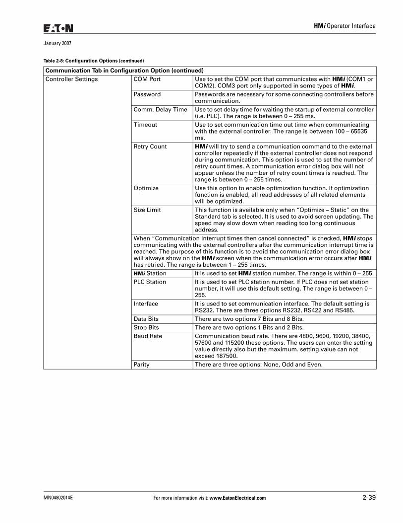
HMi Operator Interface
January 2007
Communication Tab in Configuration Option (continued)
Controller Settings COM Port Use to set the COM port that communicates with HMi (COM1 or COM2). COM3 port only supported in some types of HMi.
Password Passwords are necessary for some connecting controllers before communication.
Comm. Delay Time Use to set delay time for waiting the startup of external controller (i.e. PLC). The range is between 0 – 255 ms.
Timeout Use to set communication time out time when communicating with the external controller. The range is between 100 – 65535 ms.
Retry Count HMi will try to send a communication command to the external controller repeatedly if the external controller does not respond during communication. This option is used to set the number of retry count times. A communication error dialog box will not appear unless the number of retry count times is reached. The range is between 0 – 255 times.
Optimize Use this option to enable optimization function. If optimization function is enabled, all read addresses of all related elements will be optimized.
Size Limit This function is available only when “Optimize – Static” on the Standard tab is selected. It is used to avoid screen updating. The speed may slow down when reading too long continuous address.
When “Communication Interrupt times then cancel connected” is checked, HMi stops communicating with the external controllers after the communication interrupt time is reached. The purpose of this function is to avoid the communication error dialog box will always show on the HMi screen when the communication error occurs after HMi has retried. The range is between 1 – 255 times.HMi Station It is used to set HMi station number. The range is within 0 – 255.PLC Station It is used to set PLC station number. If PLC does not set station
number, it will use this default setting. The range is between 0 – 255.
Interface It is used to set communication interface. The default setting is RS232. There are three options RS232, RS422 and RS485.
Data Bits There are two options 7 Bits and 8 Bits.Stop Bits There are two options 1 Bits and 2 Bits.Baud Rate Communication baud rate. There are 4800, 9600, 19200, 38400,
57600 and 115200 these options. The users can enter the setting value directly also but the maximum. setting value can not exceed 187500.
Parity There are three options: None, Odd and Even.
Table 2-8: Configuration Options (continued)
MN04802014E For more information visit: www.EatonElectrical.com 2-39
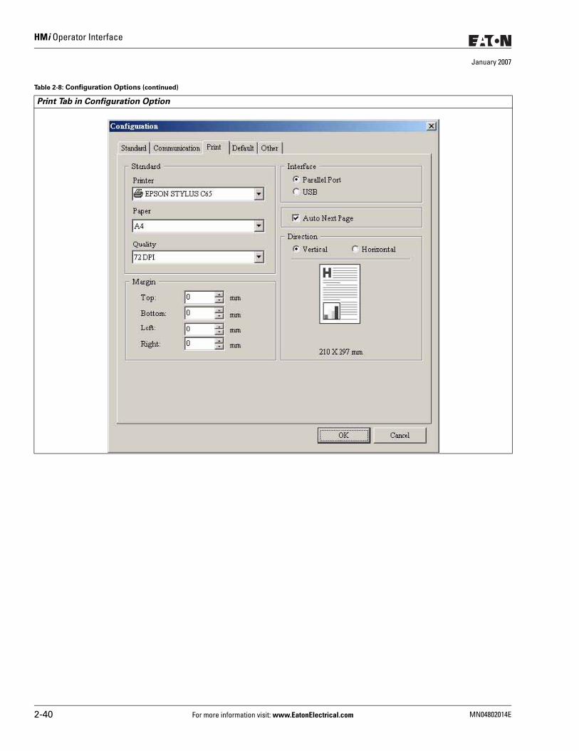
HMi Operator Interface
January 2007
Print Tab in Configuration Option
Table 2-8: Configuration Options (continued)
2-40 For more information visit: www.EatonElectrical.com MN04802014E
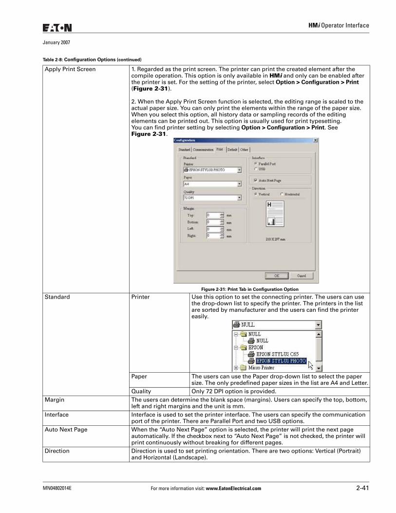
HMi Operator Interface
January 2007
Apply Print Screen 1. Regarded as the print screen. The printer can print the created element after the compile operation. This option is only available in HMi and only can be enabled after the printer is set. For the setting of the printer, select Option > Configuration > Print (Figure 2-31).
2. When the Apply Print Screen function is selected, the editing range is scaled to the actual paper size. You can only print the elements within the range of the paper size. When you select this option, all history data or sampling records of the editing elements can be printed out. This option is usually used for print typesetting. You can find printer setting by selecting Option > Configuration > Print. See Figure 2-31.
Figure 2-31: Print Tab in Configuration Option
Standard Printer Use this option to set the connecting printer. The users can use the drop-down list to specify the printer. The printers in the list are sorted by manufacturer and the users can find the printer easily.
Paper The users can use the Paper drop-down list to select the paper size. The only predefined paper sizes in the list are A4 and Letter.
Quality Only 72 DPI option is provided.Margin The users can determine the blank space (margins). Users can specify the top, bottom,
left and right margins and the unit is mm. Interface Interface is used to set the printer interface. The users can specify the communication
port of the printer. There are Parallel Port and two USB options. Auto Next Page When the “Auto Next Page” option is selected, the printer will print the next page
automatically. If the checkbox next to “Auto Next Page” is not checked, the printer will print continuously without breaking for different pages.
Direction Direction is used to set printing orientation. There are two options: Vertical (Portrait) and Horizontal (Landscape).
Table 2-8: Configuration Options (continued)
MN04802014E For more information visit: www.EatonElectrical.com 2-41
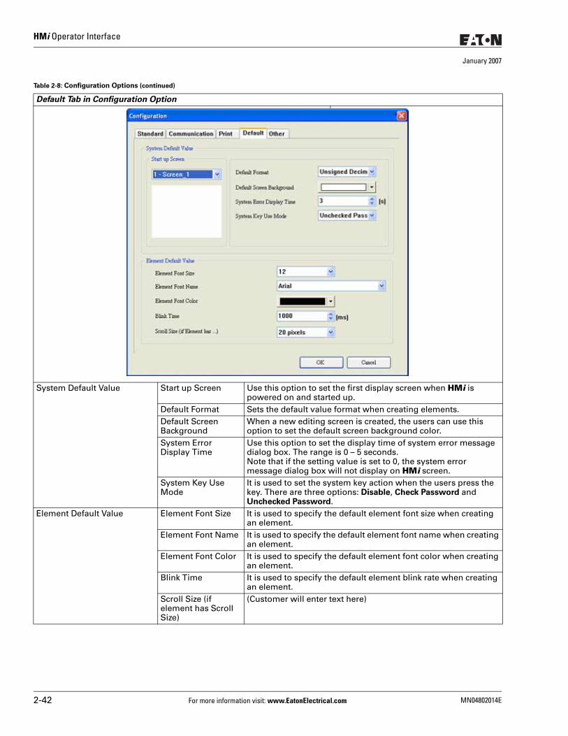
HMi Operator Interface
January 2007
Default Tab in Configuration Option
System Default Value Start up Screen Use this option to set the first display screen when HMi is powered on and started up.
Default Format Sets the default value format when creating elements.Default Screen Background
When a new editing screen is created, the users can use this option to set the default screen background color.
System Error Display Time
Use this option to set the display time of system error message dialog box. The range is 0 – 5 seconds. Note that if the setting value is set to 0, the system error message dialog box will not display on HMi screen.
System Key Use Mode
It is used to set the system key action when the users press the key. There are three options: Disable, Check Password and Unchecked Password.
Element Default Value Element Font Size It is used to specify the default element font size when creating an element.
Element Font Name It is used to specify the default element font name when creating an element.
Element Font Color It is used to specify the default element font color when creating an element.
Blink Time It is used to specify the default element blink rate when creating an element.
Scroll Size (if element has Scroll Size)
(Customer will enter text here)
Table 2-8: Configuration Options (continued)
2-42 For more information visit: www.EatonElectrical.com MN04802014E
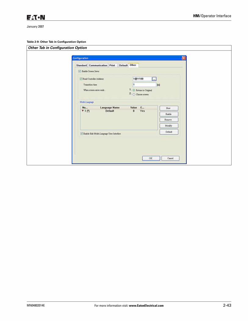
HMi Operator Interface
January 2007
Table 2-9: Other Tab in Configuration Option
Other Tab in Configuration Option
MN04802014E For more information visit: www.EatonElectrical.com 2-43
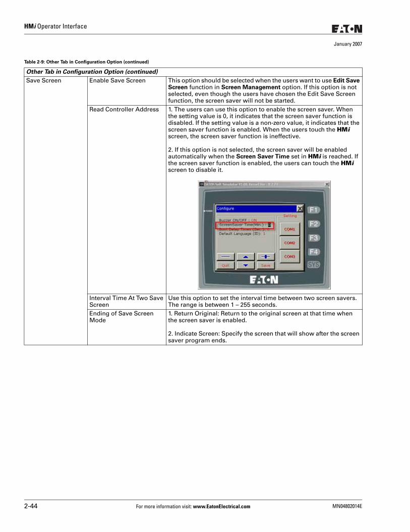
HMi Operator Interface
January 2007
Save Screen Enable Save Screen This option should be selected when the users want to use Edit Save Screen function in Screen Management option. If this option is not selected, even though the users have chosen the Edit Save Screen function, the screen saver will not be started.
Read Controller Address 1. The users can use this option to enable the screen saver. When the setting value is 0, it indicates that the screen saver function is disabled. If the setting value is a non-zero value, it indicates that the screen saver function is enabled. When the users touch the HMi screen, the screen saver function is ineffective.
2. If this option is not selected, the screen saver will be enabled automatically when the Screen Saver Time set in HMi is reached. If the screen saver function is enabled, the users can touch the HMi screen to disable it.
Interval Time At Two Save Screen
Use this option to set the interval time between two screen savers. The range is between 1 – 255 seconds.
Ending of Save Screen Mode
1. Return Original: Return to the original screen at that time when the screen saver is enabled.
2. Indicate Screen: Specify the screen that will show after the screen saver program ends.
Table 2-9: Other Tab in Configuration Option (continued)
Other Tab in Configuration Option (continued)
2-44 For more information visit: www.EatonElectrical.com MN04802014E
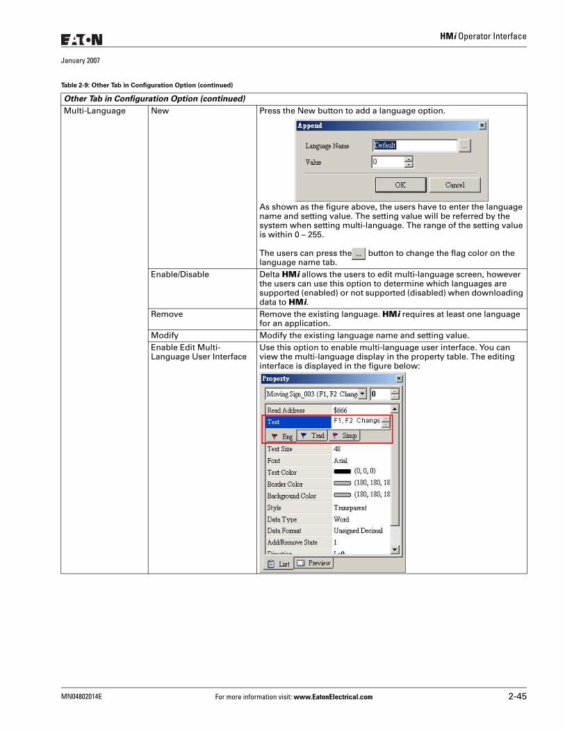
HMi Operator Interface
January 2007
Multi-Language New Press the New button to add a language option.
As shown as the figure above, the users have to enter the language name and setting value. The setting value will be referred by the system when setting multi-language. The range of the setting value is within 0 – 255.
The users can press the button to change the flag color on the language name tab.
Enable/Disable Delta HMi allows the users to edit multi-language screen, however the users can use this option to determine which languages are supported (enabled) or not supported (disabled) when downloading data to HMi.
Remove Remove the existing language. HMi requires at least one language for an application.
Modify Modify the existing language name and setting value.Enable Edit Multi-Language User Interface
Use this option to enable multi-language user interface. You can view the multi-language display in the property table. The editing interface is displayed in the figure below:
Table 2-9: Other Tab in Configuration Option (continued)
Other Tab in Configuration Option (continued)
MN04802014E For more information visit: www.EatonElectrical.com 2-45
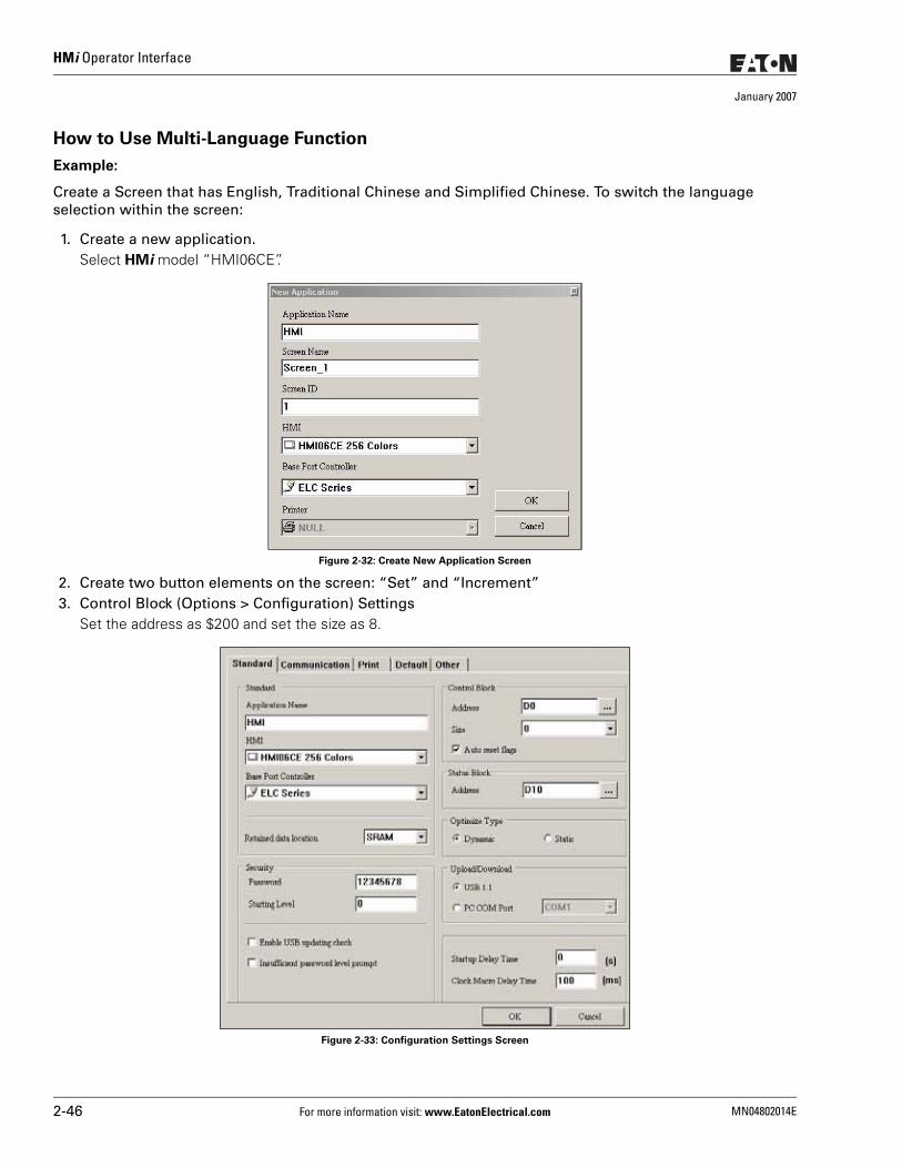
HMi Operator Interface
January 2007
How to Use Multi-Language Function
Example:
Create a Screen that has English, Traditional Chinese and Simplified Chinese. To switch the language selection within the screen:
1. Create a new application. Select HMi model “HMI06CE”.
Figure 2-32: Create New Application Screen
2. Create two button elements on the screen: “Set” and “Increment”3. Control Block (Options > Configuration) Settings
Set the address as $200 and set the size as 8.
Figure 2-33: Configuration Settings Screen
2-46 For more information visit: www.EatonElectrical.com MN04802014E
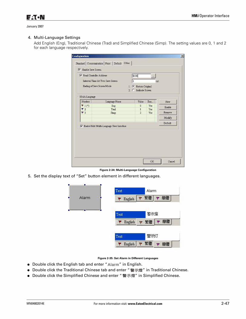
HMi Operator Interface
January 2007
4. Multi-Language SettingsAdd English (Eng), Traditional Chinese (Trad) and Simplified Chinese (Simp). The setting values are 0, 1 and 2 for each language respectively.
Figure 2-34: Multi-Language Configuration
5. Set the display text of “Set” button element in different languages.
Figure 2-35: Set Alarm in Different Languages
● Double click the English tab and enter “ ” in English. ● Double click the Traditional Chinese tab and enter “ ” in Traditional Chinese. ● Double click the Simplified Chinese and enter “ ” in Simplified Chinese.
Alarm警示燈
警示燈
MN04802014E For more information visit: www.EatonElectrical.com 2-47
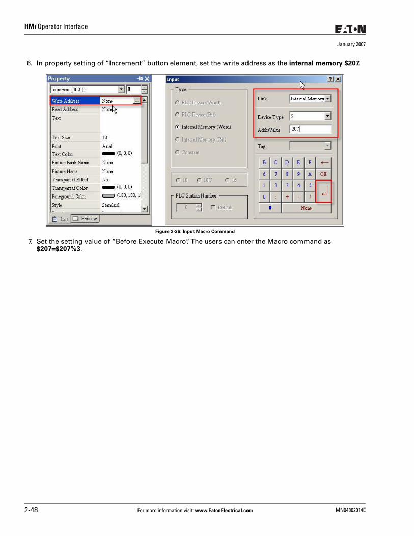
HMi Operator Interface
January 2007
6. In property setting of “Increment” button element, set the write address as the internal memory $207.
Figure 2-36: Input Macro Command
7. Set the setting value of “Before Execute Macro”. The users can enter the Macro command as $207=$207%3.
2-48 For more information visit: www.EatonElectrical.com MN04802014E
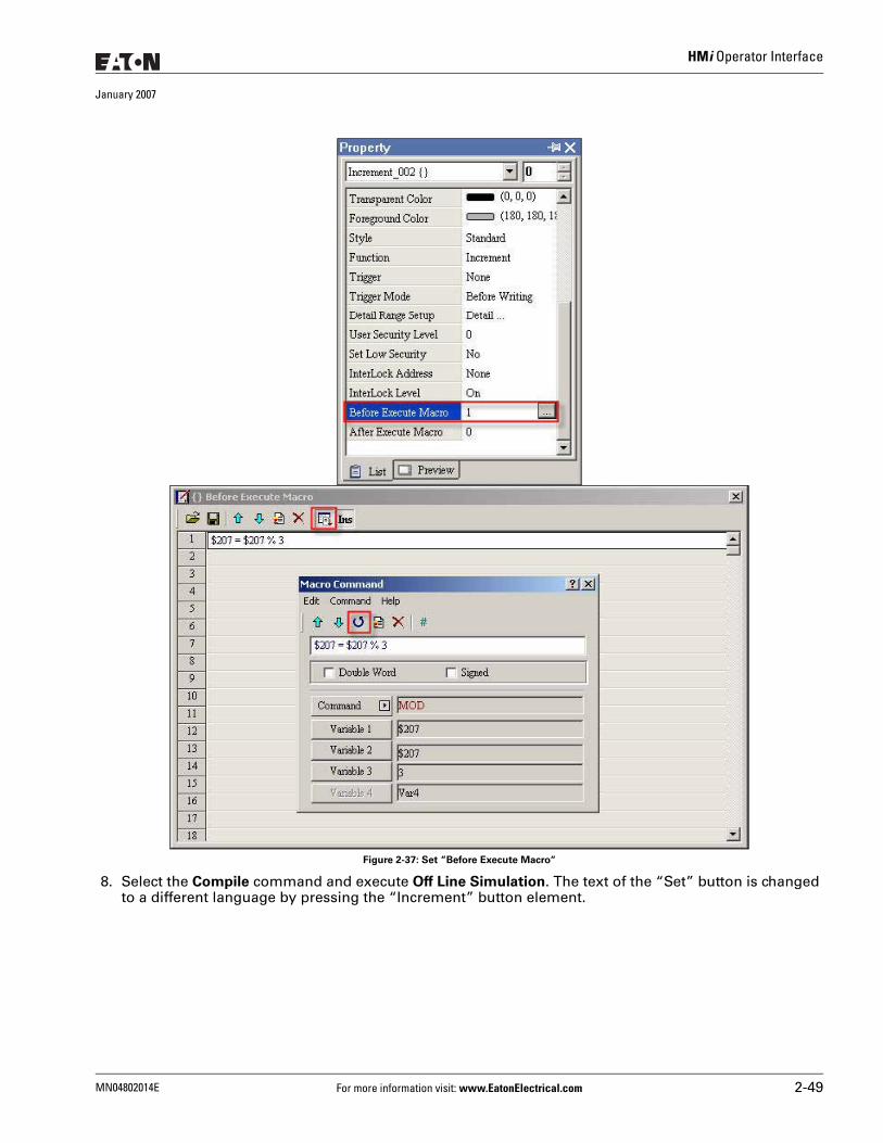
HMi Operator Interface
January 2007
Figure 2-37: Set “Before Execute Macro“
8. Select the Compile command and execute Off Line Simulation. The text of the “Set” button is changed to a different language by pressing the “Increment” button element.
MN04802014E For more information visit: www.EatonElectrical.com 2-49
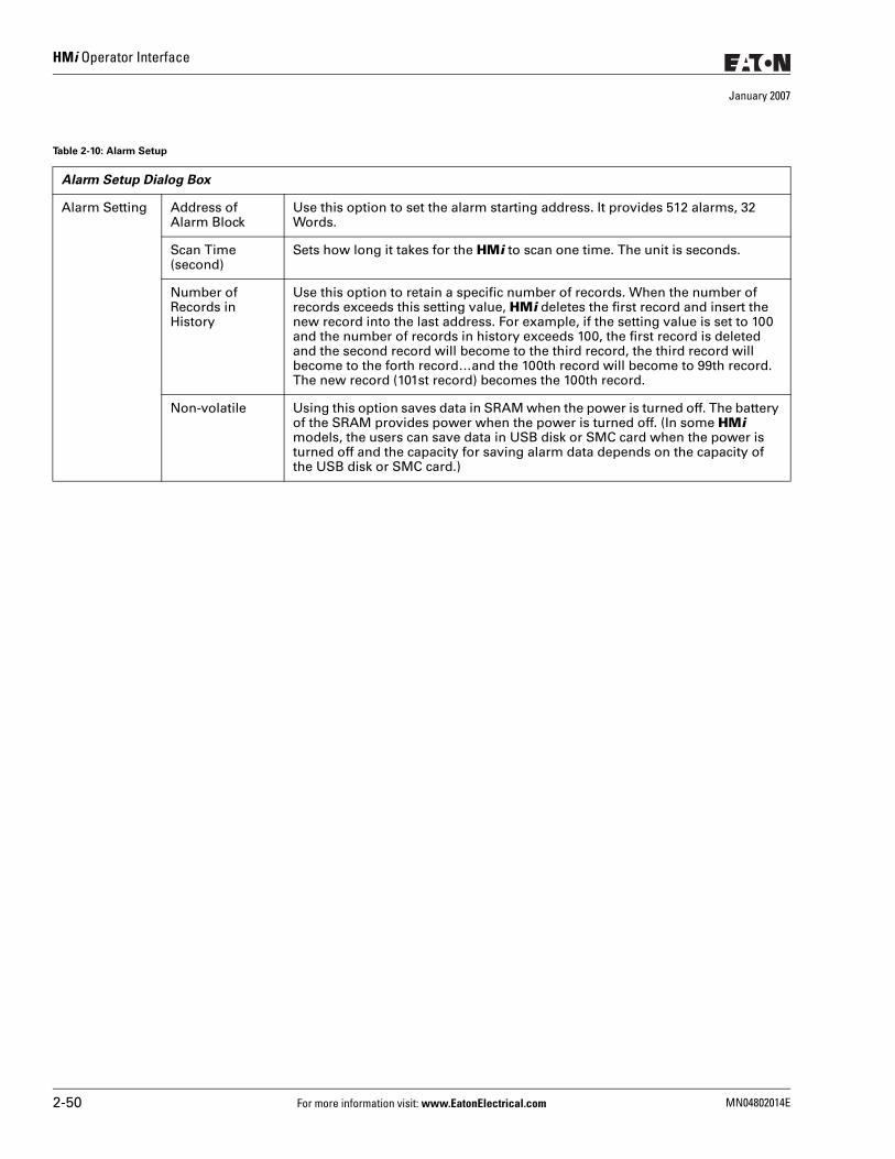
HMi Operator Interface
January 2007
Table 2-10: Alarm Setup
Alarm Setup Dialog Box
Alarm Setting Address of Alarm Block
Use this option to set the alarm starting address. It provides 512 alarms, 32 Words.
Scan Time (second)
Sets how long it takes for the HMi to scan one time. The unit is seconds.
Number of Records in History
Use this option to retain a specific number of records. When the number of records exceeds this setting value, HMi deletes the first record and insert the new record into the last address. For example, if the setting value is set to 100 and the number of records in history exceeds 100, the first record is deleted and the second record will become to the third record, the third record will become to the forth record…and the 100th record will become to 99th record. The new record (101st record) becomes the 100th record.
Non-volatile Using this option saves data in SRAM when the power is turned off. The battery of the SRAM provides power when the power is turned off. (In some HMi models, the users can save data in USB disk or SMC card when the power is turned off and the capacity for saving alarm data depends on the capacity of the USB disk or SMC card.)
2-50 For more information visit: www.EatonElectrical.com MN04802014E
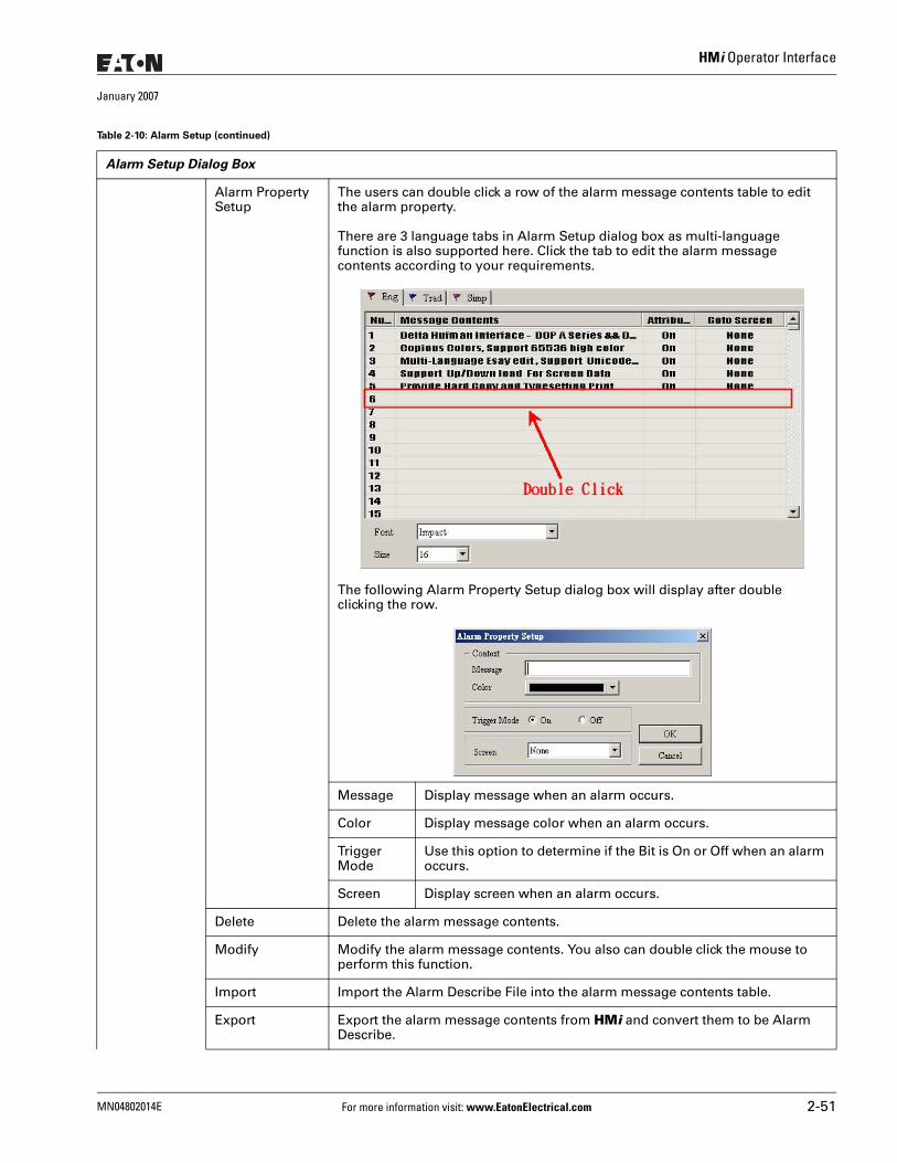
HMi Operator Interface
January 2007
Alarm Property Setup
The users can double click a row of the alarm message contents table to edit the alarm property.
There are 3 language tabs in Alarm Setup dialog box as multi-language function is also supported here. Click the tab to edit the alarm message contents according to your requirements.
The following Alarm Property Setup dialog box will display after double clicking the row.
Message Display message when an alarm occurs.
Color Display message color when an alarm occurs.
Trigger Mode
Use this option to determine if the Bit is On or Off when an alarm occurs.
Screen Display screen when an alarm occurs.
Delete Delete the alarm message contents.
Modify Modify the alarm message contents. You also can double click the mouse to perform this function.
Import Import the Alarm Describe File into the alarm message contents table.
Export Export the alarm message contents from HMi and convert them to be Alarm Describe.
Table 2-10: Alarm Setup (continued)
Alarm Setup Dialog Box
MN04802014E For more information visit: www.EatonElectrical.com 2-51
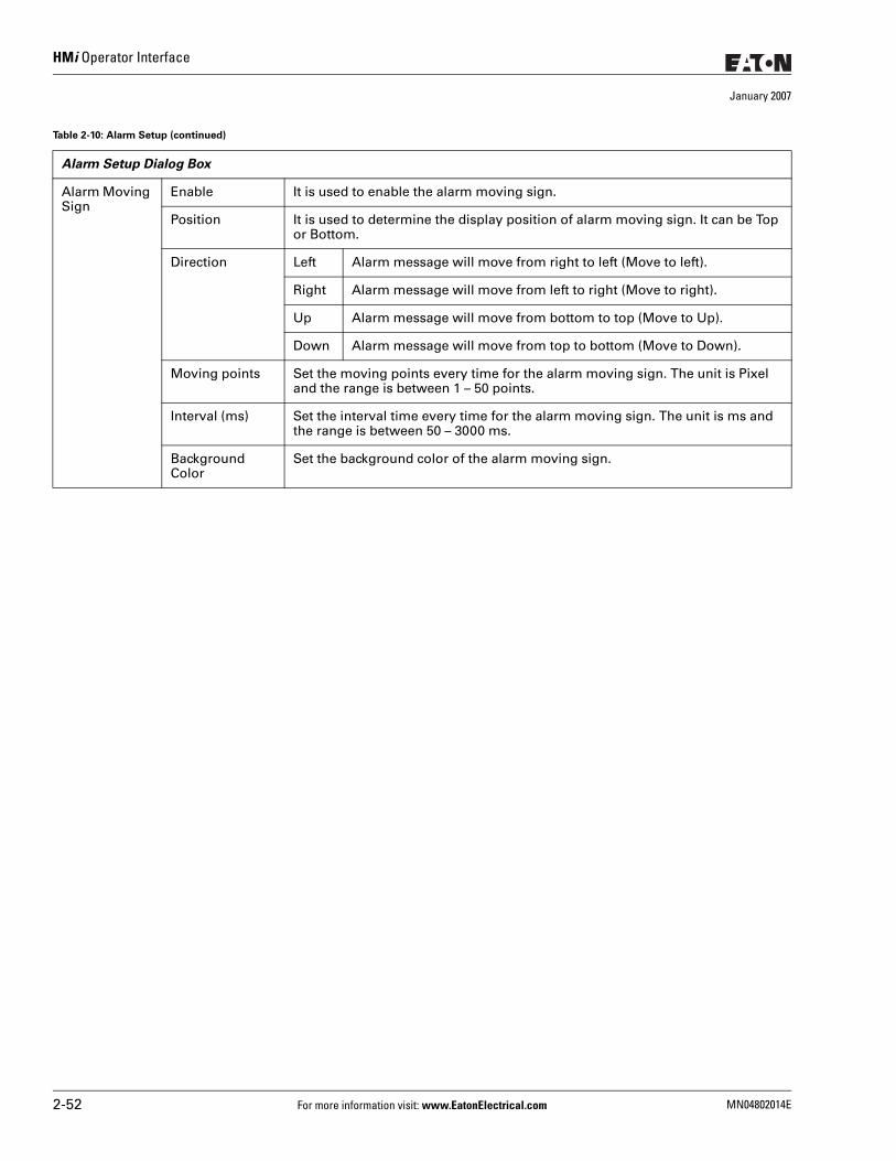
HMi Operator Interface
January 2007
Alarm Moving Sign
Enable It is used to enable the alarm moving sign.
Position It is used to determine the display position of alarm moving sign. It can be Top or Bottom.
Direction Left Alarm message will move from right to left (Move to left).
Right Alarm message will move from left to right (Move to right).
Up Alarm message will move from bottom to top (Move to Up).
Down Alarm message will move from top to bottom (Move to Down).
Moving points Set the moving points every time for the alarm moving sign. The unit is Pixel and the range is between 1 – 50 points.
Interval (ms) Set the interval time every time for the alarm moving sign. The unit is ms and the range is between 50 – 3000 ms.
Background Color
Set the background color of the alarm moving sign.
Table 2-10: Alarm Setup (continued)
Alarm Setup Dialog Box
2-52 For more information visit: www.EatonElectrical.com MN04802014E
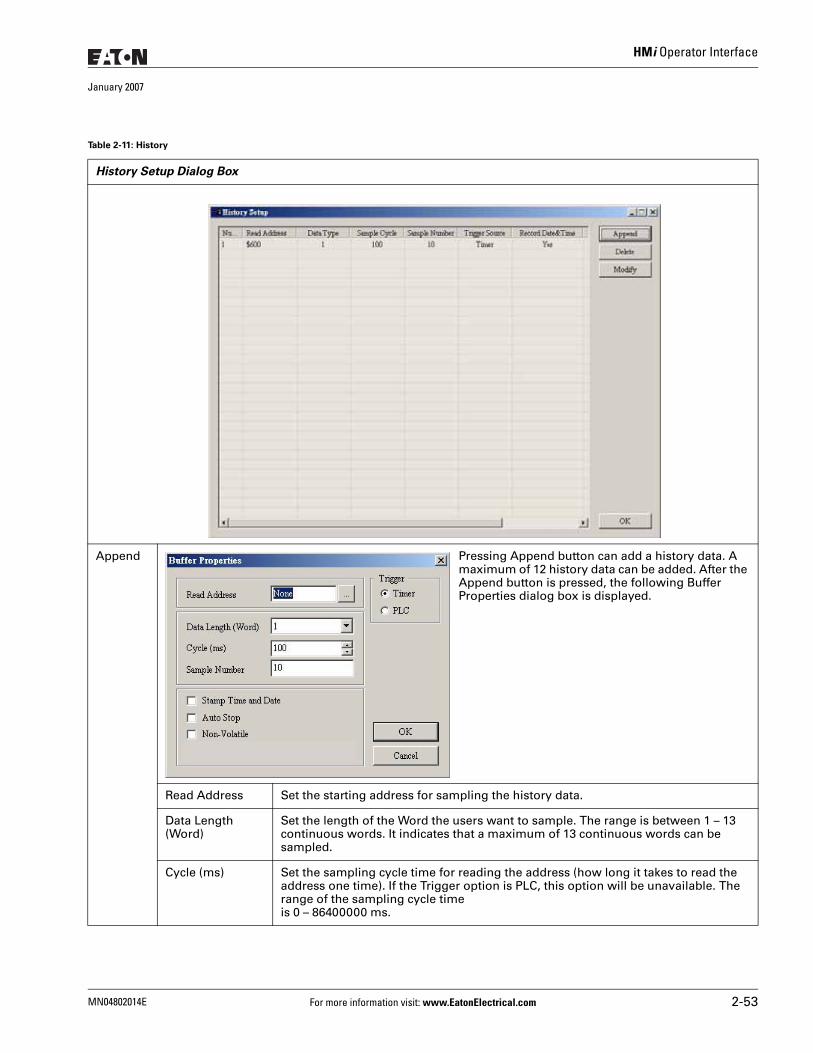
HMi Operator Interface
January 2007
Table 2-11: History
History Setup Dialog Box
Append Pressing Append button can add a history data. A maximum of 12 history data can be added. After the Append button is pressed, the following Buffer Properties dialog box is displayed.
Read Address Set the starting address for sampling the history data.
Data Length (Word)
Set the length of the Word the users want to sample. The range is between 1 – 13 continuous words. It indicates that a maximum of 13 continuous words can be sampled.
Cycle (ms) Set the sampling cycle time for reading the address (how long it takes to read the address one time). If the Trigger option is PLC, this option will be unavailable. The range of the sampling cycle time is 0 – 86400000 ms.
MN04802014E For more information visit: www.EatonElectrical.com 2-53
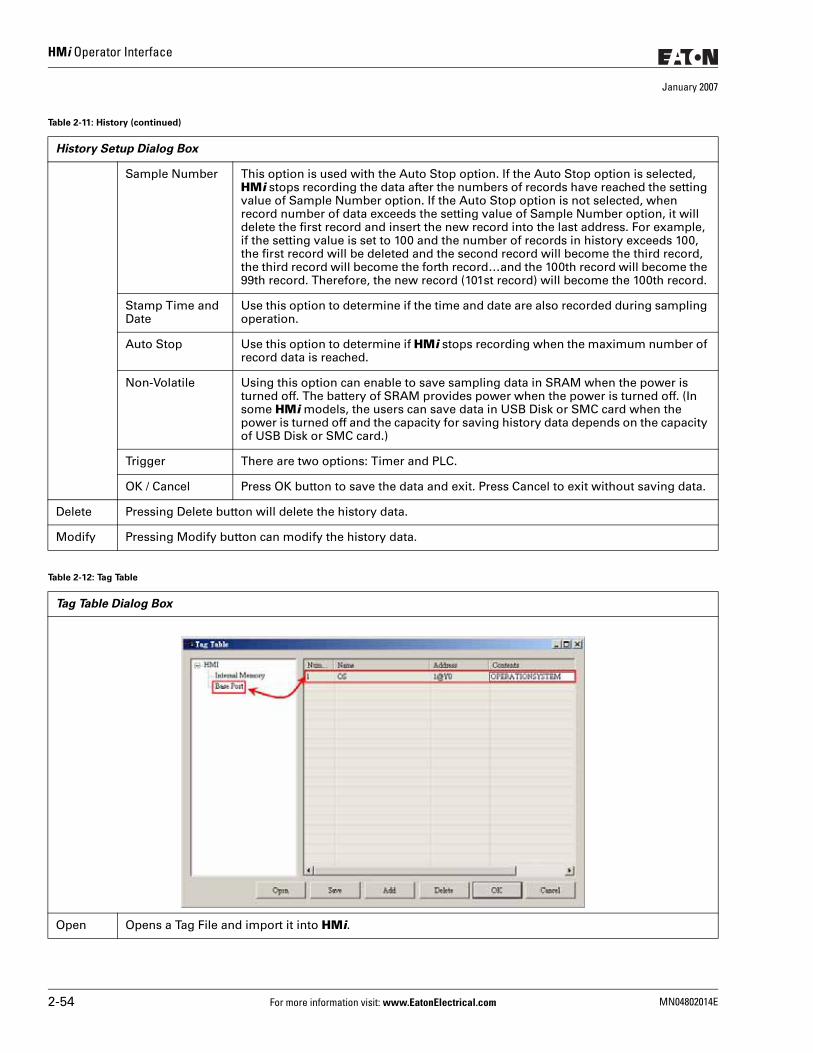
HMi Operator Interface
January 2007
Sample Number This option is used with the Auto Stop option. If the Auto Stop option is selected, HMi stops recording the data after the numbers of records have reached the setting value of Sample Number option. If the Auto Stop option is not selected, when record number of data exceeds the setting value of Sample Number option, it will delete the first record and insert the new record into the last address. For example, if the setting value is set to 100 and the number of records in history exceeds 100, the first record will be deleted and the second record will become the third record, the third record will become the forth record…and the 100th record will become the 99th record. Therefore, the new record (101st record) will become the 100th record.
Stamp Time and Date
Use this option to determine if the time and date are also recorded during sampling operation.
Auto Stop Use this option to determine if HMi stops recording when the maximum number of record data is reached.
Non-Volatile Using this option can enable to save sampling data in SRAM when the power is turned off. The battery of SRAM provides power when the power is turned off. (In some HMi models, the users can save data in USB Disk or SMC card when the power is turned off and the capacity for saving history data depends on the capacity of USB Disk or SMC card.)
Trigger There are two options: Timer and PLC.
OK / Cancel Press OK button to save the data and exit. Press Cancel to exit without saving data.
Delete Pressing Delete button will delete the history data.
Modify Pressing Modify button can modify the history data.
Table 2-12: Tag Table
Tag Table Dialog Box
Open Opens a Tag File and import it into HMi.
Table 2-11: History (continued)
History Setup Dialog Box
2-54 For more information visit: www.EatonElectrical.com MN04802014E
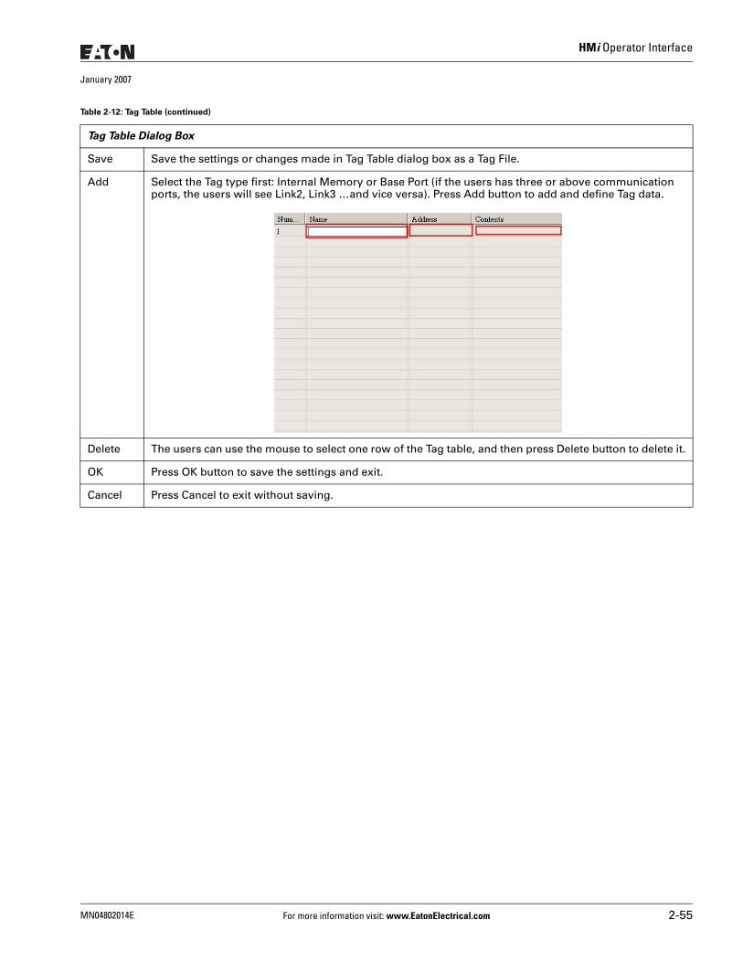
HMi Operator Interface
January 2007
Save Save the settings or changes made in Tag Table dialog box as a Tag File.
Add Select the Tag type first: Internal Memory or Base Port (if the users has three or above communication ports, the users will see Link2, Link3 …and vice versa). Press Add button to add and define Tag data.
Delete The users can use the mouse to select one row of the Tag table, and then press Delete button to delete it.
OK Press OK button to save the settings and exit.
Cancel Press Cancel to exit without saving.
Table 2-12: Tag Table (continued)
Tag Table Dialog Box
MN04802014E For more information visit: www.EatonElectrical.com 2-55
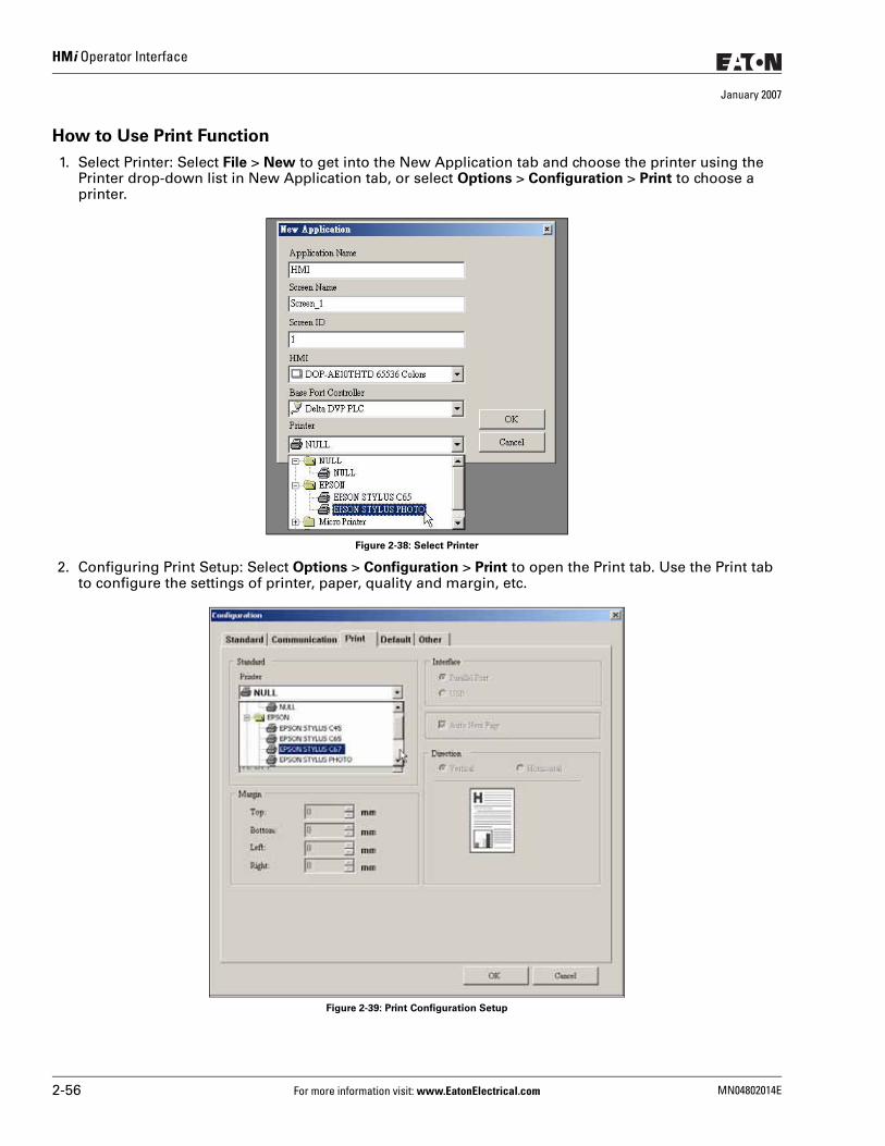
HMi Operator Interface
January 2007
How to Use Print Function
1. Select Printer: Select File > New to get into the New Application tab and choose the printer using the Printer drop-down list in New Application tab, or select Options > Configuration > Print to choose a printer.
Figure 2-38: Select Printer
2. Configuring Print Setup: Select Options > Configuration > Print to open the Print tab. Use the Print tab to configure the settings of printer, paper, quality and margin, etc.
Figure 2-39: Print Configuration Setup
2-56 For more information visit: www.EatonElectrical.com MN04802014E
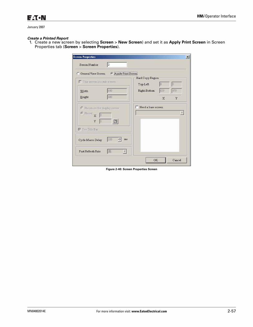
HMi Operator Interface
January 2007
Create a Printed Report 1. Create a new screen by selecting Screen > New Screen) and set it as Apply Print Screen in Screen
Properties tab (Screen > Screen Properties).
Figure 2-40: Screen Properties Screen
MN04802014E For more information visit: www.EatonElectrical.com 2-57
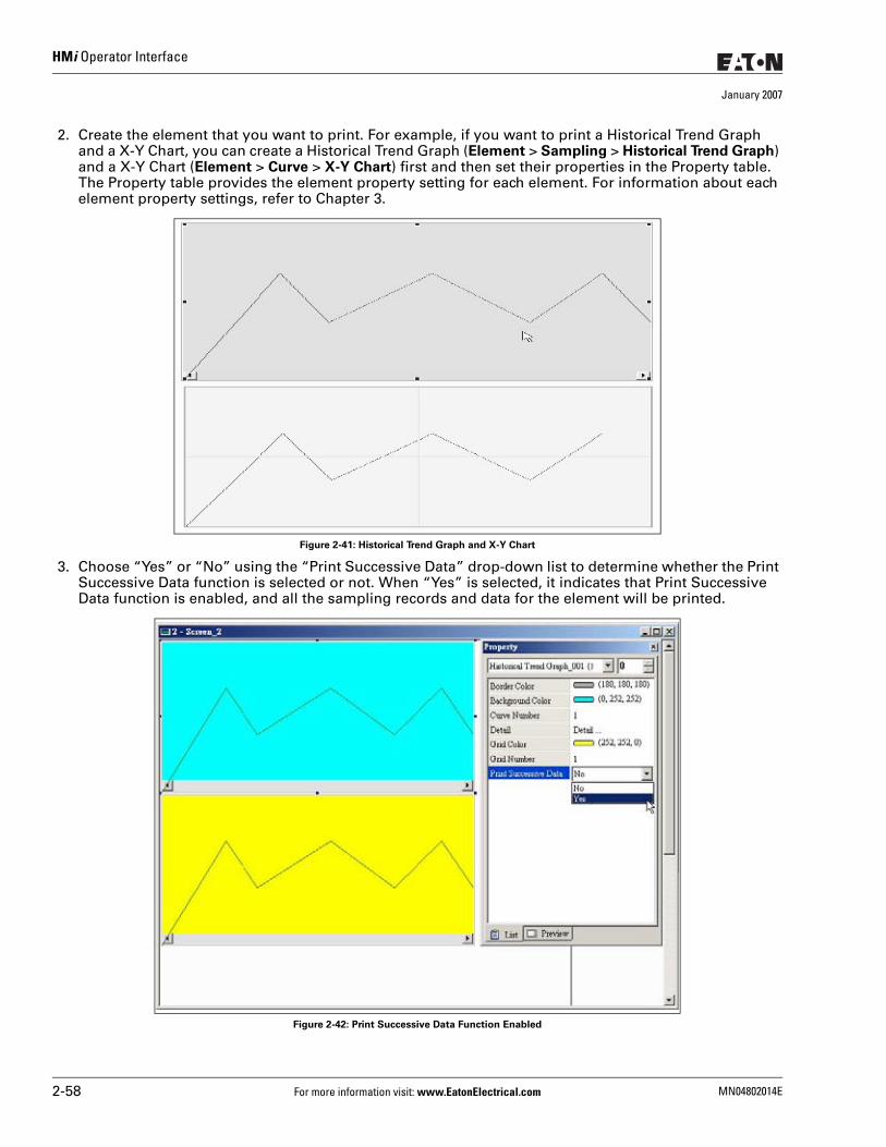
HMi Operator Interface
January 2007
2. Create the element that you want to print. For example, if you want to print a Historical Trend Graph and a X-Y Chart, you can create a Historical Trend Graph (Element > Sampling > Historical Trend Graph) and a X-Y Chart (Element > Curve > X-Y Chart) first and then set their properties in the Property table. The Property table provides the element property setting for each element. For information about each element property settings, refer to Chapter 3.
Figure 2-41: Historical Trend Graph and X-Y Chart
3. Choose “Yes” or “No” using the “Print Successive Data” drop-down list to determine whether the Print Successive Data function is selected or not. When “Yes” is selected, it indicates that Print Successive Data function is enabled, and all the sampling records and data for the element will be printed.
Figure 2-42: Print Successive Data Function Enabled
2-58 For more information visit: www.EatonElectrical.com MN04802014E
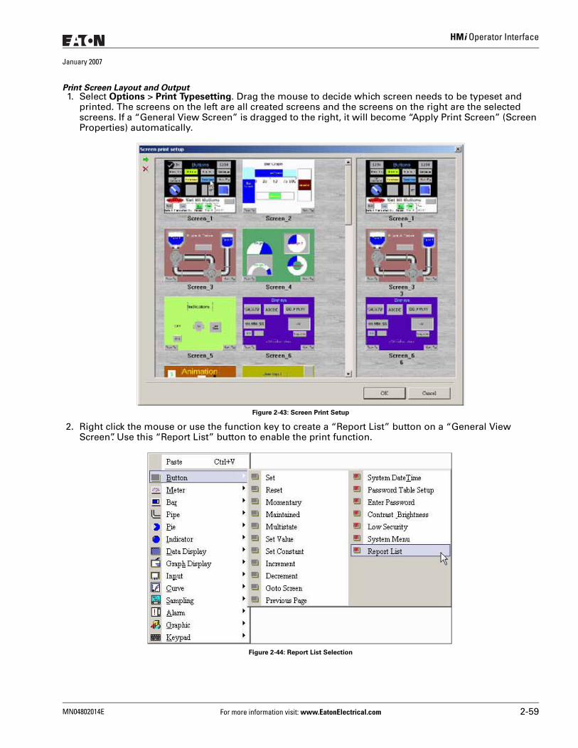
HMi Operator Interface
January 2007
Print Screen Layout and Output 1. Select Options > Print Typesetting. Drag the mouse to decide which screen needs to be typeset and
printed. The screens on the left are all created screens and the screens on the right are the selected screens. If a “General View Screen” is dragged to the right, it will become “Apply Print Screen” (Screen Properties) automatically.
Figure 2-43: Screen Print Setup
2. Right click the mouse or use the function key to create a “Report List” button on a “General View Screen”. Use this “Report List” button to enable the print function.
Figure 2-44: Report List Selection
MN04802014E For more information visit: www.EatonElectrical.com 2-59
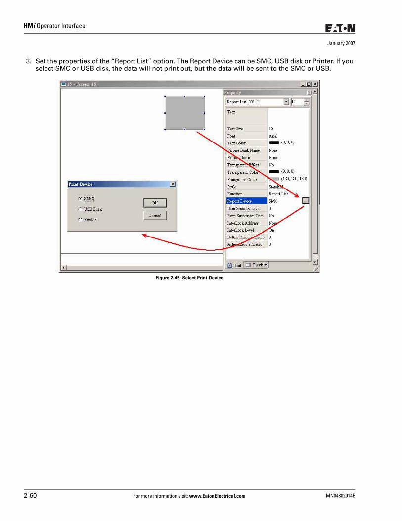
HMi Operator Interface
January 2007
3. Set the properties of the “Report List” option. The Report Device can be SMC, USB disk or Printer. If you select SMC or USB disk, the data will not print out, but the data will be sent to the SMC or USB.
Figure 2-45: Select Print Device
2-60 For more information visit: www.EatonElectrical.com MN04802014E
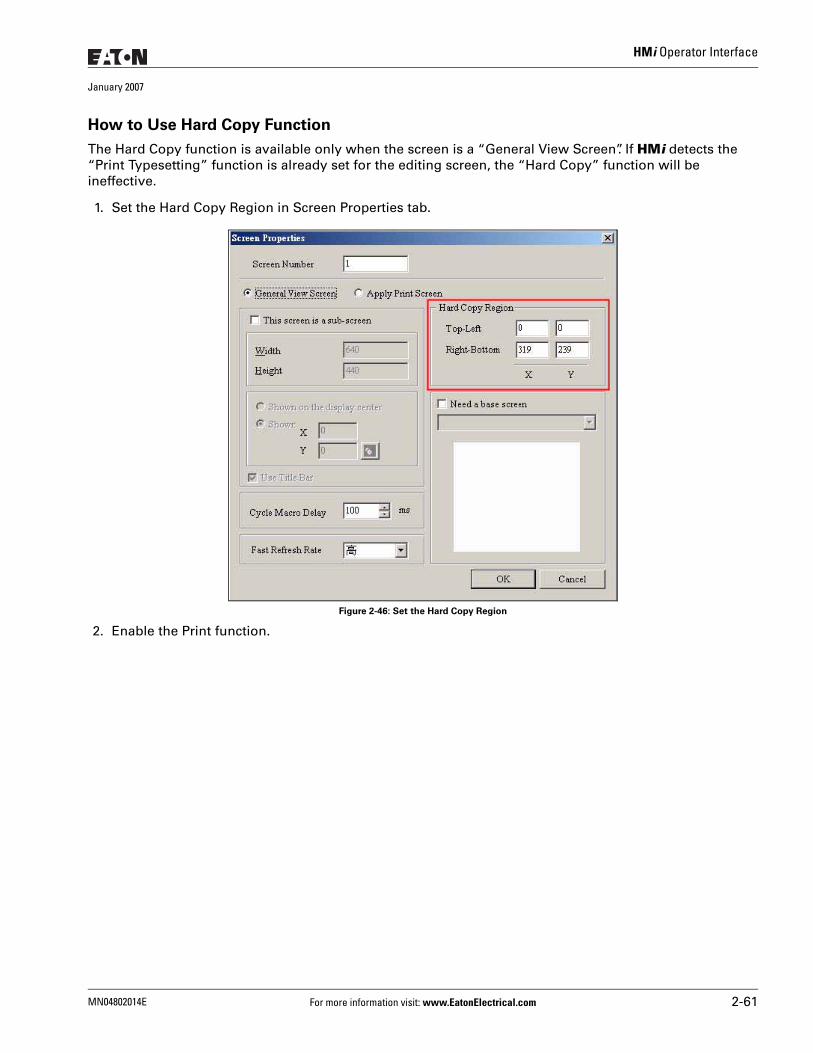
HMi Operator Interface
January 2007
How to Use Hard Copy Function
The Hard Copy function is available only when the screen is a “General View Screen”. If HMi detects the “Print Typesetting” function is already set for the editing screen, the “Hard Copy” function will be ineffective.
1. Set the Hard Copy Region in Screen Properties tab.
Figure 2-46: Set the Hard Copy Region
2. Enable the Print function.
MN04802014E For more information visit: www.EatonElectrical.com 2-61
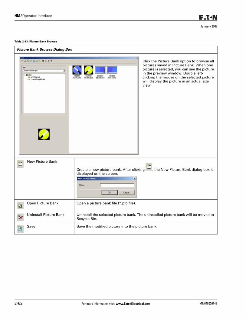
HMi Operator Interface
January 2007
Table 2-13: Picture Bank Browse
Picture Bank Browse Dialog Box
Click the Picture Bank option to browse all pictures saved in Picture Bank. When one picture is selected, you can see the picture in the preview window. Double left-clicking the mouse on the selected picture will display the picture in an actual size view.
New Picture Bank
Create a new picture bank. After clicking , the New Picture Bank dialog box is displayed on the screen.
Open Picture Bank Open a picture bank file (*.pib file).
Uninstall Picture Bank Uninstall the selected picture bank. The uninstalled picture bank will be moved to Recycle Bin.
Save Save the modified picture into the picture bank.
2-62 For more information visit: www.EatonElectrical.com MN04802014E
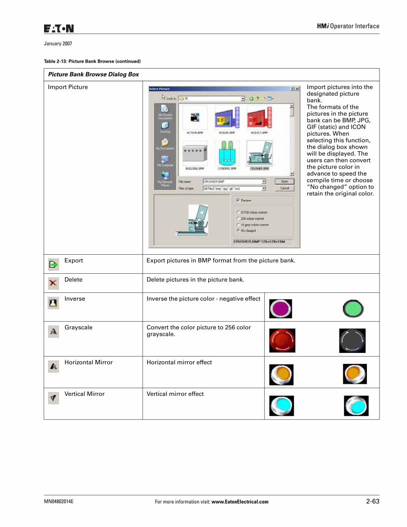
HMi Operator Interface
January 2007
Import Picture Import pictures into the designated picture bank. The formats of the pictures in the picture bank can be BMP, JPG, GIF (static) and ICON pictures. When selecting this function, the dialog box shown will be displayed. The users can then convert the picture color in advance to speed the compile time or choose “No changed” option to retain the original color.
Export Export pictures in BMP format from the picture bank.
Delete Delete pictures in the picture bank.
Inverse Inverse the picture color - negative effect
Grayscale Convert the color picture to 256 color grayscale.
Horizontal Mirror Horizontal mirror effect
Vertical Mirror Vertical mirror effect
Table 2-13: Picture Bank Browse (continued)
Picture Bank Browse Dialog Box
MN04802014E For more information visit: www.EatonElectrical.com 2-63
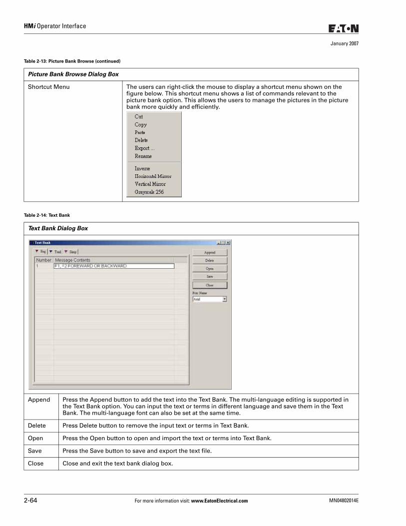
HMi Operator Interface
January 2007
Shortcut Menu The users can right-click the mouse to display a shortcut menu shown on the figure below. This shortcut menu shows a list of commands relevant to the picture bank option. This allows the users to manage the pictures in the picture bank more quickly and efficiently.
Table 2-14: Text Bank
Text Bank Dialog Box
Append Press the Append button to add the text into the Text Bank. The multi-language editing is supported in the Text Bank option. You can input the text or terms in different language and save them in the Text Bank. The multi-language font can also be set at the same time.
Delete Press Delete button to remove the input text or terms in Text Bank.
Open Press the Open button to open and import the text or terms into Text Bank.
Save Press the Save button to save and export the text file.
Close Close and exit the text bank dialog box.
Table 2-13: Picture Bank Browse (continued)
Picture Bank Browse Dialog Box
2-64 For more information visit: www.EatonElectrical.com MN04802014E
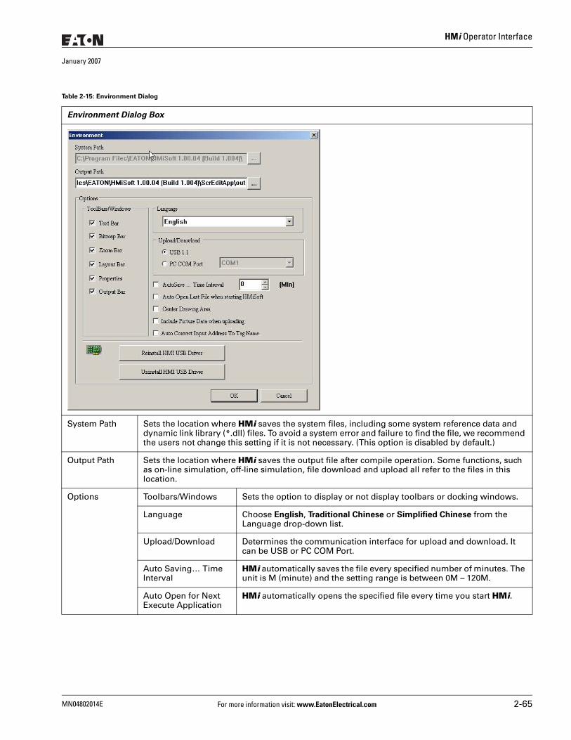
HMi Operator Interface
January 2007
Table 2-15: Environment Dialog
Environment Dialog Box
System Path Sets the location where HMi saves the system files, including some system reference data and dynamic link library (*.dll) files. To avoid a system error and failure to find the file, we recommend the users not change this setting if it is not necessary. (This option is disabled by default.)
Output Path Sets the location where HMi saves the output file after compile operation. Some functions, such as on-line simulation, off-line simulation, file download and upload all refer to the files in this location.
Options Toolbars/Windows Sets the option to display or not display toolbars or docking windows.
Language Choose English, Traditional Chinese or Simplified Chinese from the Language drop-down list.
Upload/Download Determines the communication interface for upload and download. It can be USB or PC COM Port.
Auto Saving… Time Interval
HMi automatically saves the file every specified number of minutes. The unit is M (minute) and the setting range is between 0M – 120M.
Auto Open for Next Execute Application
HMi automatically opens the specified file every time you start HMi.
MN04802014E For more information visit: www.EatonElectrical.com 2-65
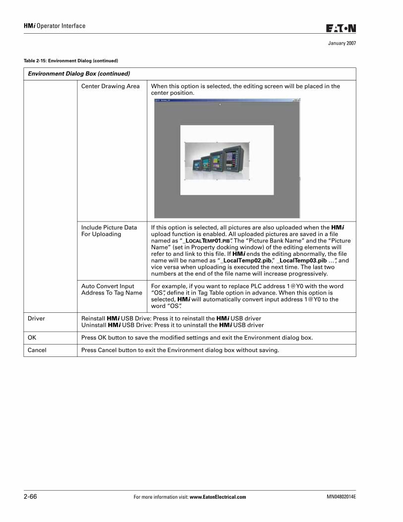
HMi Operator Interface
January 2007
Center Drawing Area When this option is selected, the editing screen will be placed in the center position.
Include Picture Data For Uploading
If this option is selected, all pictures are also uploaded when the HMi upload function is enabled. All uploaded pictures are saved in a file named as “_LOCALTEMP01.PIB”. The “Picture Bank Name” and the “Picture Name” (set in Property docking window) of the editing elements will refer to and link to this file. If HMi ends the editing abnormally, the file name will be named as “_LocalTemp02.pib,” _LocalTemp03.pib …”, and vice versa when uploading is executed the next time. The last two numbers at the end of the file name will increase progressively.
Auto Convert Input Address To Tag Name
For example, if you want to replace PLC address 1@Y0 with the word “OS”, define it in Tag Table option in advance. When this option is selected, HMi will automatically convert input address 1@Y0 to the word “OS”.
Driver Reinstall HMi USB Drive: Press it to reinstall the HMi USB driverUninstall HMi USB Drive: Press it to uninstall the HMi USB driver
OK Press OK button to save the modified settings and exit the Environment dialog box.
Cancel Press Cancel button to exit the Environment dialog box without saving.
Table 2-15: Environment Dialog (continued)
Environment Dialog Box (continued)
2-66 For more information visit: www.EatonElectrical.com MN04802014E
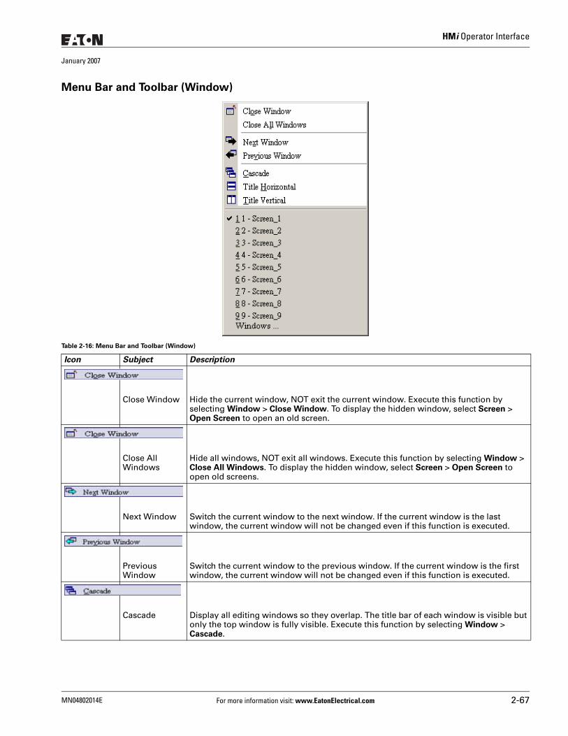
HMi Operator Interface
January 2007
Menu Bar and Toolbar (Window)
Table 2-16: Menu Bar and Toolbar (Window)
Icon Subject Description
Close Window Hide the current window, NOT exit the current window. Execute this function by selecting Window > Close Window. To display the hidden window, select Screen > Open Screen to open an old screen.
Close All Windows
Hide all windows, NOT exit all windows. Execute this function by selecting Window > Close All Windows. To display the hidden window, select Screen > Open Screen to open old screens.
Next Window Switch the current window to the next window. If the current window is the last window, the current window will not be changed even if this function is executed.
Previous Window
Switch the current window to the previous window. If the current window is the first window, the current window will not be changed even if this function is executed.
Cascade Display all editing windows so they overlap. The title bar of each window is visible but only the top window is fully visible. Execute this function by selecting Window > Cascade.
MN04802014E For more information visit: www.EatonElectrical.com 2-67
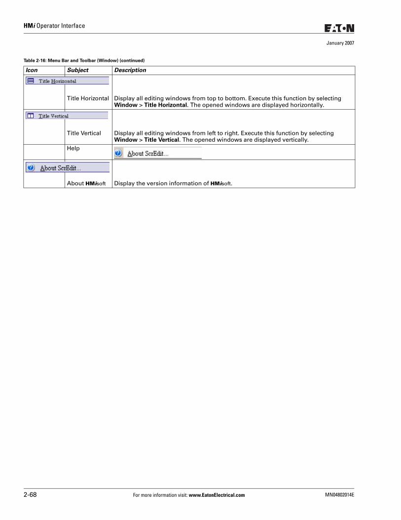
HMi Operator Interface
January 2007
Title Horizontal Display all editing windows from top to bottom. Execute this function by selecting Window > Title Horizontal. The opened windows are displayed horizontally.
Title Vertical Display all editing windows from left to right. Execute this function by selecting Window > Title Vertical. The opened windows are displayed vertically.
Help
About HMisoft Display the version information of HMisoft.
Table 2-16: Menu Bar and Toolbar (Window) (continued)
Icon Subject Description
2-68 For more information visit: www.EatonElectrical.com MN04802014E
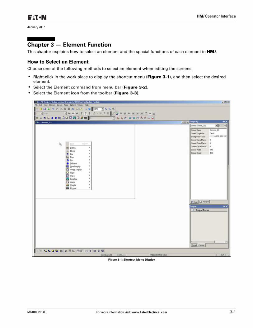
HMi Operator Interface
January 2007
Chapter 3 — Element FunctionThis chapter explains how to select an element and the special functions of each element in HMi.
How to Select an Element
Choose one of the following methods to select an element when editing the screens:
● Right-click in the work place to display the shortcut menu (Figure 3-1), and then select the desired element.
● Select the Element command from menu bar (Figure 3-2). ● Select the Element icon from the toolbar (Figure 3-3).
Figure 3-1: Shortcut Menu Display
MN04802014E For more information visit: www.EatonElectrical.com 3-1
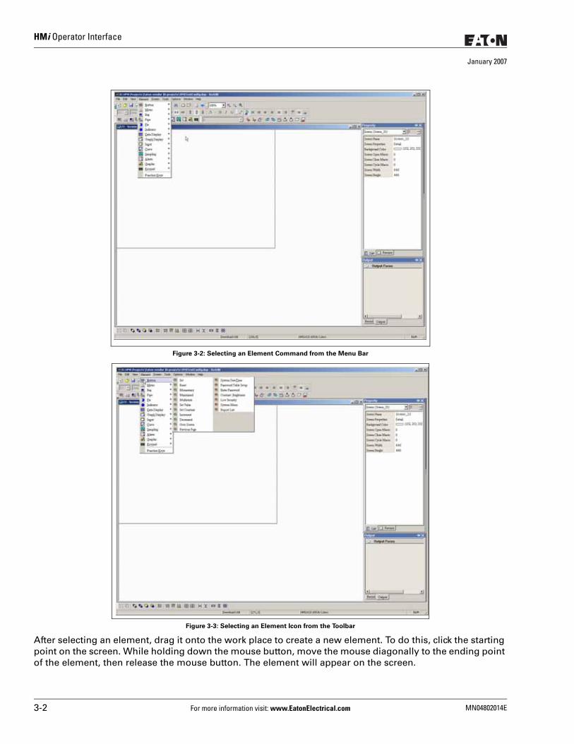
HMi Operator Interface
January 2007
Figure 3-2: Selecting an Element Command from the Menu Bar
Figure 3-3: Selecting an Element Icon from the Toolbar
After selecting an element, drag it onto the work place to create a new element. To do this, click the starting point on the screen. While holding down the mouse button, move the mouse diagonally to the ending point of the element, then release the mouse button. The element will appear on the screen.
3-2 For more information visit: www.EatonElectrical.com MN04802014E
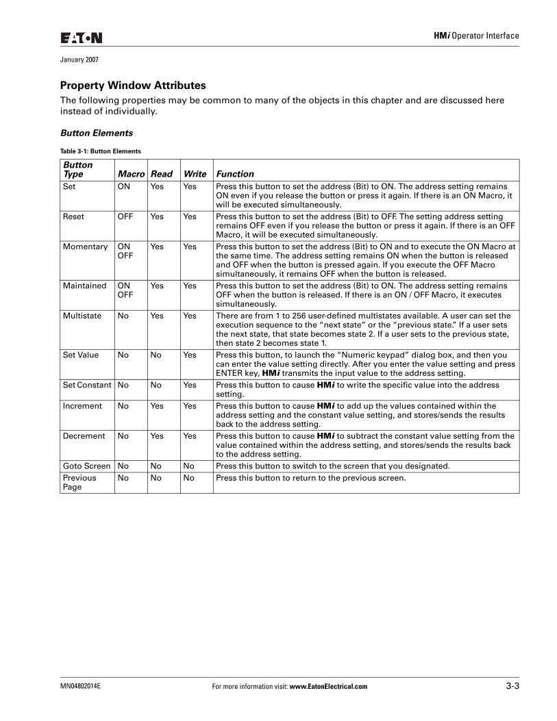
HMi Operator Interface
January 2007
Property Window Attributes
The following properties may be common to many of the objects in this chapter and are discussed here instead of individually.
Button Elements
Table 3-1: Button Elements
Button Type Macro Read Write Function
Set ON Yes Yes Press this button to set the address (Bit) to ON. The address setting remains ON even if you release the button or press it again. If there is an ON Macro, it will be executed simultaneously.
Reset OFF Yes Yes Press this button to set the address (Bit) to OFF. The setting address setting remains OFF even if you release the button or press it again. If there is an OFF Macro, it will be executed simultaneously.
Momentary ONOFF
Yes Yes Press this button to set the address (Bit) to ON and to execute the ON Macro at the same time. The address setting remains ON when the button is released and OFF when the button is pressed again. If you execute the OFF Macro simultaneously, it remains OFF when the button is released.
Maintained ONOFF
Yes Yes Press this button to set the address (Bit) to ON. The address setting remains OFF when the button is released. If there is an ON / OFF Macro, it executes simultaneously.
Multistate No Yes Yes There are from 1 to 256 user-defined multistates available. A user can set the execution sequence to the “next state” or the “previous state.” If a user sets the next state, that state becomes state 2. If a user sets to the previous state, then state 2 becomes state 1.
Set Value No No Yes Press this button, to launch the “Numeric keypad” dialog box, and then you can enter the value setting directly. After you enter the value setting and press ENTER key, HMi transmits the input value to the address setting.
Set Constant No No Yes Press this button to cause HMi to write the specific value into the address setting.
Increment No Yes Yes Press this button to cause HMi to add up the values contained within the address setting and the constant value setting, and stores/sends the results back to the address setting.
Decrement No Yes Yes Press this button to cause HMi to subtract the constant value setting from the value contained within the address setting, and stores/sends the results back to the address setting.
Goto Screen No No No Press this button to switch to the screen that you designated.Previous Page
No No No Press this button to return to the previous screen.
MN04802014E For more information visit: www.EatonElectrical.com 3-3
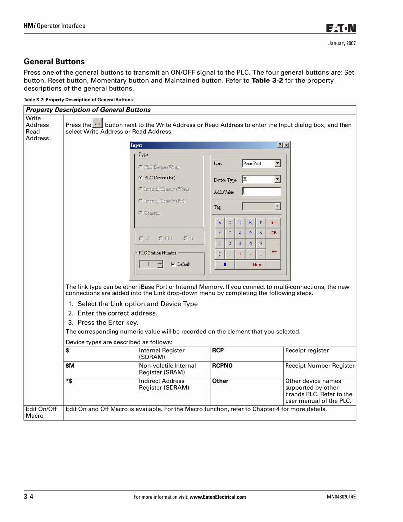
HMi Operator Interface
January 2007
General Buttons
Press one of the general buttons to transmit an ON/OFF signal to the PLC. The four general buttons are: Set button, Reset button, Momentary button and Maintained button. Refer to Table 3-2 for the property descriptions of the general buttons.
Table 3-2: Property Description of General Buttons
Property Description of General Buttons
Write AddressRead Address
Press the button next to the Write Address or Read Address to enter the Input dialog box, and then select Write Address or Read Address.
The link type can be ether iBase Port or Internal Memory. If you connect to multi-connections, the new connections are added into the Link drop-down menu by completing the following steps.
1. Select the Link option and Device Type2. Enter the correct address.3. Press the Enter key.
The corresponding numeric value will be recorded on the element that you selected.
Device types are described as follows:$ Internal Register
(SDRAM)RCP Receipt register
$M Non-volatile Internal Register (SRAM)
RCPNO Receipt Number Register
*$ Indirect Address Register (SDRAM)
Other Other device names supported by other brands PLC. Refer to the user manual of the PLC.
Edit On/Off Macro
Edit On and Off Macro is available. For the Macro function, refer to Chapter 4 for more details.
3-4 For more information visit: www.EatonElectrical.com MN04802014E
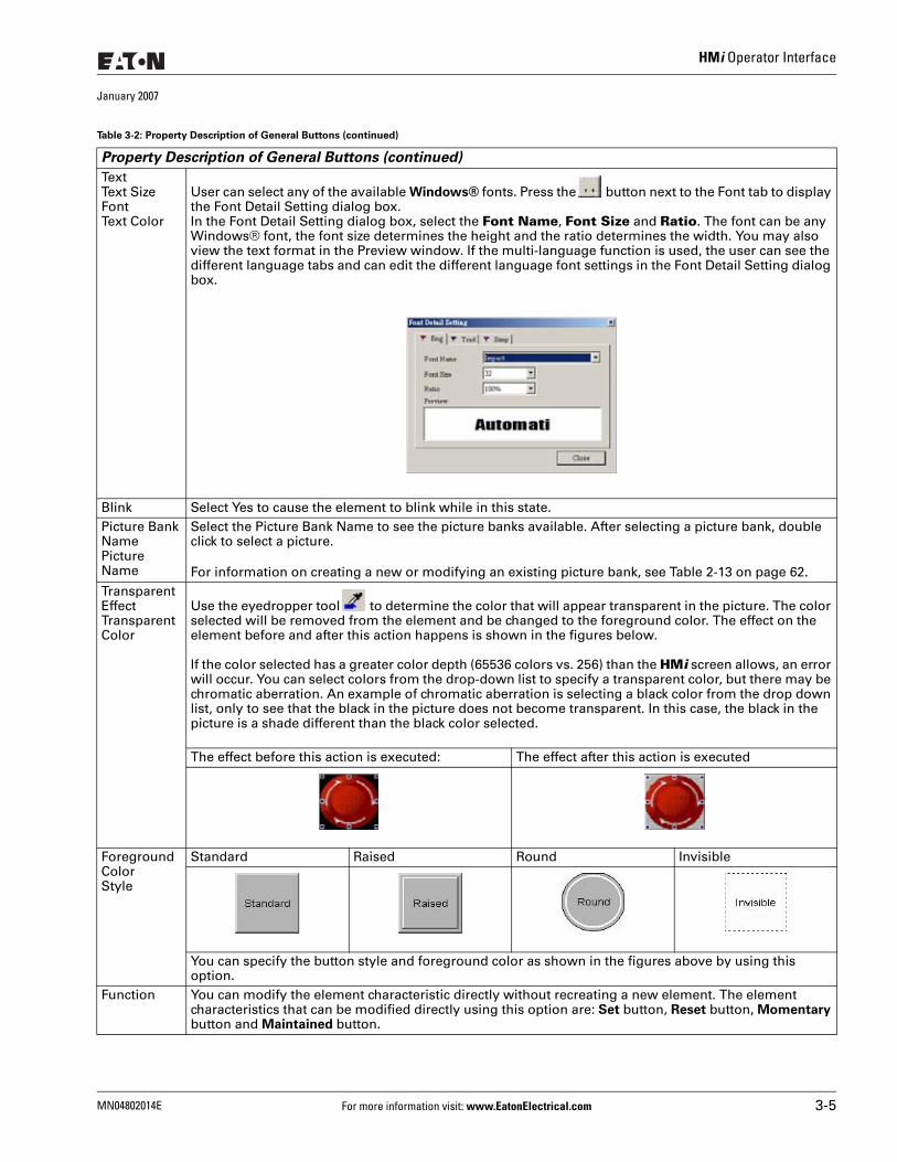
HMi Operator Interface
January 2007
TextText SizeFontText Color
User can select any of the available Windows® fonts. Press the button next to the Font tab to display the Font Detail Setting dialog box.In the Font Detail Setting dialog box, select the Font Name, Font Size and Ratio. The font can be any Windows® font, the font size determines the height and the ratio determines the width. You may also view the text format in the Preview window. If the multi-language function is used, the user can see the different language tabs and can edit the different language font settings in the Font Detail Setting dialog box.
Blink Select Yes to cause the element to blink while in this state. Picture Bank NamePicture Name
Select the Picture Bank Name to see the picture banks available. After selecting a picture bank, double click to select a picture.
For information on creating a new or modifying an existing picture bank, see Table 2-13 on page 62. Transparent EffectTransparent Color
Use the eyedropper tool to determine the color that will appear transparent in the picture. The color selected will be removed from the element and be changed to the foreground color. The effect on the element before and after this action happens is shown in the figures below.
If the color selected has a greater color depth (65536 colors vs. 256) than the HMi screen allows, an error will occur. You can select colors from the drop-down list to specify a transparent color, but there may be chromatic aberration. An example of chromatic aberration is selecting a black color from the drop down list, only to see that the black in the picture does not become transparent. In this case, the black in the picture is a shade different than the black color selected.
The effect before this action is executed: The effect after this action is executed
Foreground ColorStyle
Standard Raised Round Invisible
You can specify the button style and foreground color as shown in the figures above by using this option.
Function You can modify the element characteristic directly without recreating a new element. The element characteristics that can be modified directly using this option are: Set button, Reset button, Momentary button and Maintained button.
Table 3-2: Property Description of General Buttons (continued)
Property Description of General Buttons (continued)
MN04802014E For more information visit: www.EatonElectrical.com 3-5
HMi Operator Interface
January 2007
Multistate Buttons
Push Time (second)
Use this option to set the active time of the button. When this option is set, the button will be active after pressing the button longer than the setting time indicated. The range set is between 0 – 10 seconds.
Data Length Bit Multistate button can have two states.Word Multistate button can have 256 states.LSB Multistate button can have 16 states.
Line Color Used to set the display color of the dynamic line element.Line Size The unit is in Pixels and the range is between 1and 8.
Table 3-3: Property Description of Multistate Buttons
Property Description of Multistate Buttons
The number state will vary by unit. In Word, the number state may be from 1 to 256; in LSB, the number state is 16; with a Bit, the number state is 2. The unit of the read/write address will vary by the value unit. If the value unit is Word or LSB, the unit of the read/write address will be the Word equivalent. If the value data type is Bit, the unit of read/write address will be Bit. After obtaining the data from the read address, it will increase or decrease gradually according to the next state or previous state and will write the new value to the write address. The change state of this button depends on the read address. If you need to add or delete the total numbers state, edit the values in only element property table.Add/Remove State
Sets the number state of multistate buttons. One to 256 states can be set if the unit is Word, 16 states can be set if the unit is LSB, and 2 states can be set if the unit is Bit.
Sequence Switches the multistate sequence (previous state/next state).
Table 3-2: Property Description of General Buttons (continued)
Property Description of General Buttons (continued)
3-6 For more information visit: www.EatonElectrical.com MN04802014E
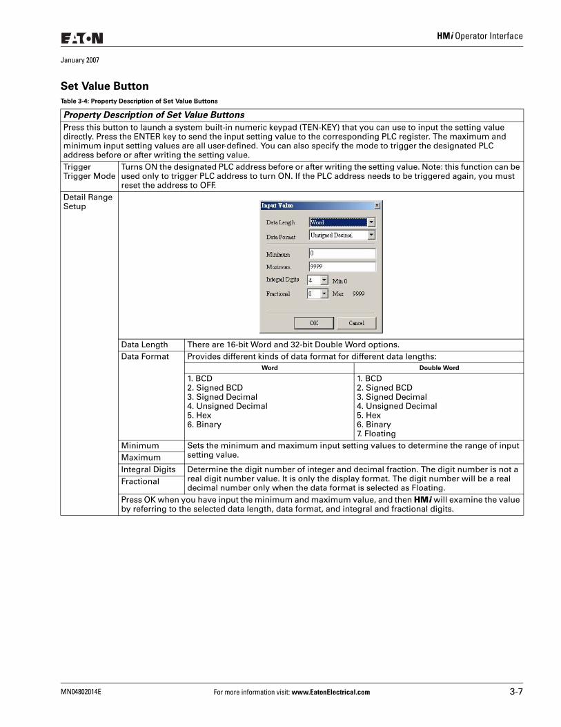
HMi Operator Interface
January 2007
Set Value Button
Table 3-4: Property Description of Set Value Buttons
Property Description of Set Value Buttons
Press this button to launch a system built-in numeric keypad (TEN-KEY) that you can use to input the setting value directly. Press the ENTER key to send the input setting value to the corresponding PLC register. The maximum and minimum input setting values are all user-defined. You can also specify the mode to trigger the designated PLC address before or after writing the setting value. TriggerTrigger Mode
Turns ON the designated PLC address before or after writing the setting value. Note: this function can be used only to trigger PLC address to turn ON. If the PLC address needs to be triggered again, you must reset the address to OFF.
Detail Range Setup
Data Length There are 16-bit Word and 32-bit Double Word options.Data Format Provides different kinds of data format for different data lengths:
Word Double Word
1. BCD2. Signed BCD3. Signed Decimal4. Unsigned Decimal5. Hex6. Binary
1. BCD2. Signed BCD3. Signed Decimal4. Unsigned Decimal5. Hex6. Binary7. Floating
Minimum Sets the minimum and maximum input setting values to determine the range of input setting value.Maximum
Integral Digits Determine the digit number of integer and decimal fraction. The digit number is not a real digit number value. It is only the display format. The digit number will be a real decimal number only when the data format is selected as Floating.
Fractional
Press OK when you have input the minimum and maximum value, and then HMi will examine the value by referring to the selected data length, data format, and integral and fractional digits.
MN04802014E For more information visit: www.EatonElectrical.com 3-7
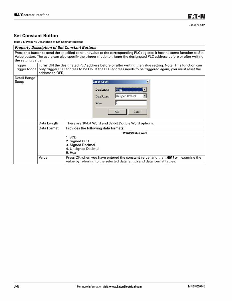
HMi Operator Interface
January 2007
Set Constant Button
Table 3-5: Property Description of Set Constant Buttons
Property Description of Set Constant Buttons
Press this button to send the specified constant value to the corresponding PLC register. It has the same function as Set Value button. The users can also specify the trigger mode to trigger the designated PLC address before or after writing the setting value. TriggerTrigger Mode
Turns ON the designated PLC address before or after writing the value setting. Note: This function can only trigger PLC address to be ON. If the PLC address needs to be triggered again, you must reset the address to OFF.
Detail Range Setup
Data Length There are 16-bit Word and 32-bit Double Word options.Data Format Provides the following data formats:
Word/Double Word
1. BCD2. Signed BCD3. Signed Decimal4. Unsigned Decimal5. Hex
Value Press OK when you have entered the constant value, and then HMi will examine the value by referring to the selected data length and data format tables.
3-8 For more information visit: www.EatonElectrical.com MN04802014E
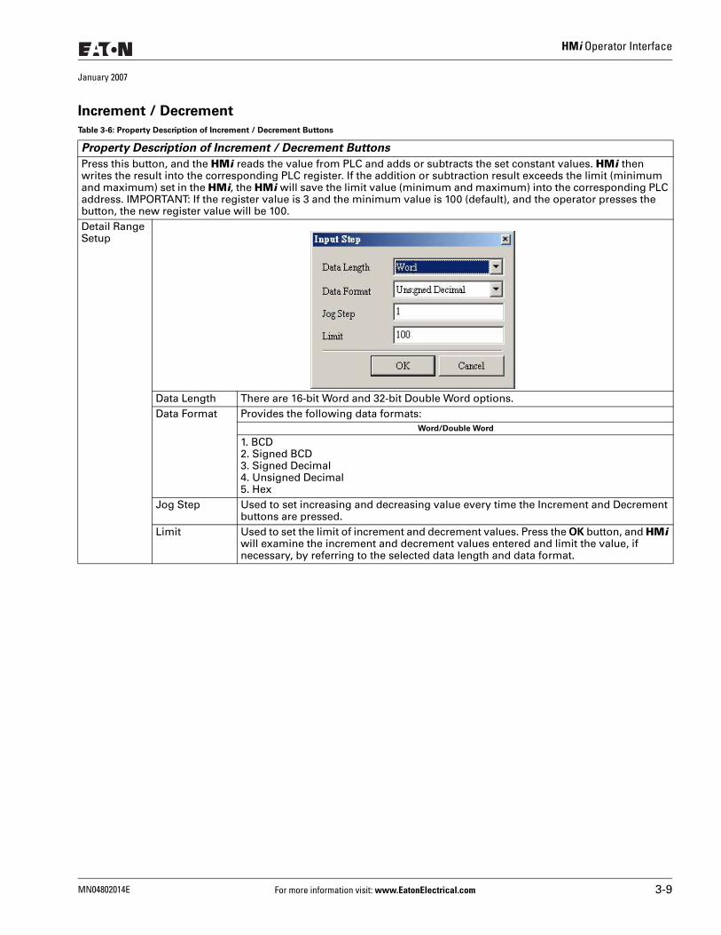
HMi Operator Interface
January 2007
Increment / Decrement
Table 3-6: Property Description of Increment / Decrement Buttons
Property Description of Increment / Decrement Buttons
Press this button, and the HMi reads the value from PLC and adds or subtracts the set constant values. HMi then writes the result into the corresponding PLC register. If the addition or subtraction result exceeds the limit (minimum and maximum) set in the HMi, the HMi will save the limit value (minimum and maximum) into the corresponding PLC address. IMPORTANT: If the register value is 3 and the minimum value is 100 (default), and the operator presses the button, the new register value will be 100.Detail Range Setup
Data Length There are 16-bit Word and 32-bit Double Word options.Data Format Provides the following data formats:
Word/Double Word
1. BCD2. Signed BCD3. Signed Decimal4. Unsigned Decimal5. Hex
Jog Step Used to set increasing and decreasing value every time the Increment and Decrement buttons are pressed.
Limit Used to set the limit of increment and decrement values. Press the OK button, and HMi will examine the increment and decrement values entered and limit the value, if necessary, by referring to the selected data length and data format.
MN04802014E For more information visit: www.EatonElectrical.com 3-9
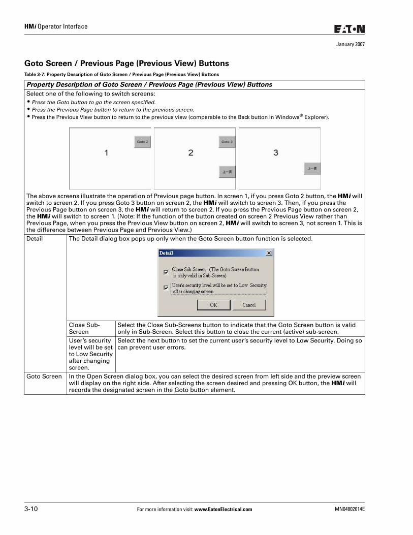
HMi Operator Interface
January 2007
Goto Screen / Previous Page (Previous View) Buttons
Table 3-7: Property Description of Goto Screen / Previous Page (Previous View) Buttons
Property Description of Goto Screen / Previous Page (Previous View) Buttons
Select one of the following to switch screens: ● Press the Goto button to go the screen specified. ● Press the Previous Page button to return to the previous screen. ● Press the Previous View button to return to the previous view (comparable to the Back button in Windows® Explorer).
The above screens illustrate the operation of Previous page button. In screen 1, if you press Goto 2 button, the HMi will switch to screen 2. If you press Goto 3 button on screen 2, the HMi will switch to screen 3. Then, if you press the Previous Page button on screen 3, the HMi will return to screen 2. If you press the Previous Page button on screen 2, the HMi will switch to screen 1. (Note: If the function of the button created on screen 2 Previous View rather than Previous Page, when you press the Previous View button on screen 2, HMi will switch to screen 3, not screen 1. This is the difference between Previous Page and Previous View.)Detail The Detail dialog box pops up only when the Goto Screen button function is selected.
Close Sub-Screen
Select the Close Sub-Screens button to indicate that the Goto Screen button is valid only in Sub-Screen. Select this button to close the current (active) sub-screen.
User’s security level will be set to Low Security after changing screen.
Select the next button to set the current user’s security level to Low Security. Doing so can prevent user errors.
Goto Screen In the Open Screen dialog box, you can select the desired screen from left side and the preview screen will display on the right side. After selecting the screen desired and pressing OK button, the HMi will records the designated screen in the Goto button element.
3-10 For more information visit: www.EatonElectrical.com MN04802014E
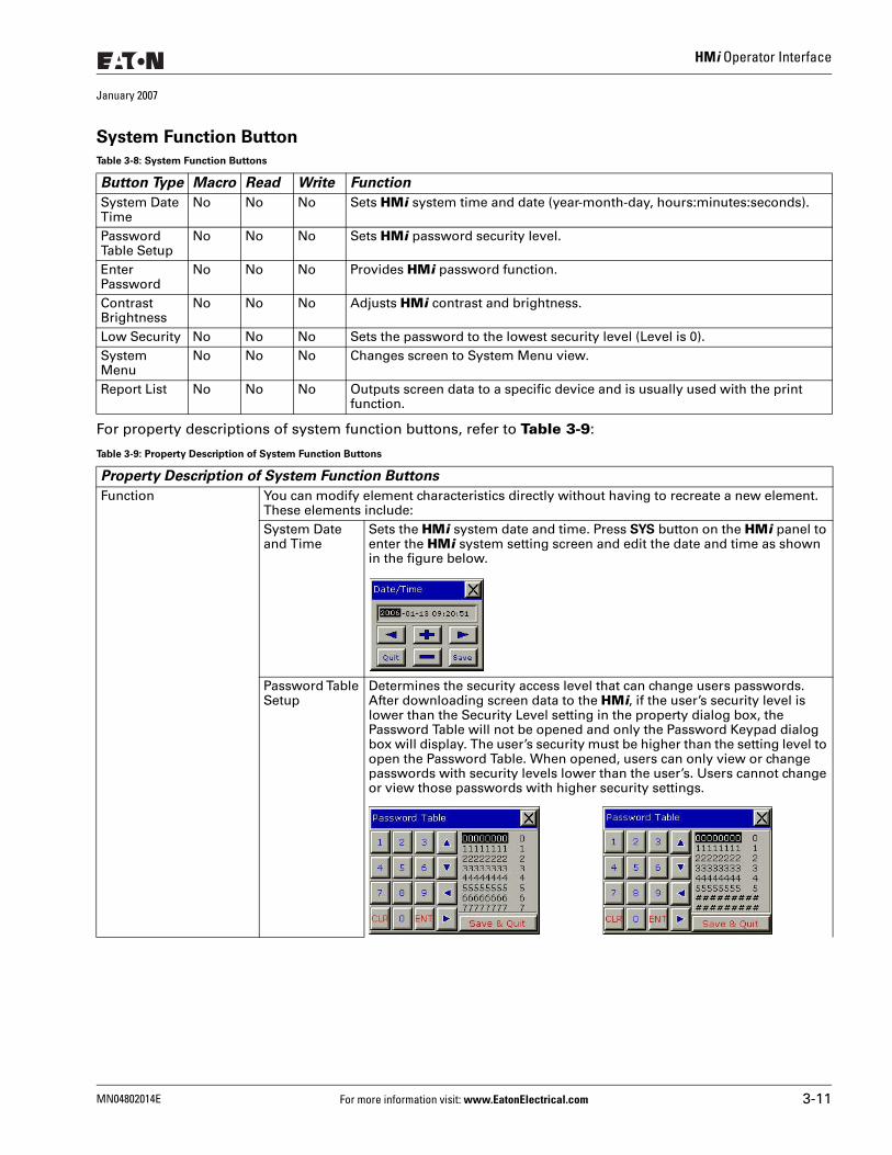
HMi Operator Interface
January 2007
System Function Button
For property descriptions of system function buttons, refer to Table 3-9:
Table 3-8: System Function Buttons
Button Type Macro Read Write Function
System Date Time
No No No Sets HMi system time and date (year-month-day, hours:minutes:seconds).
Password Table Setup
No No No Sets HMi password security level.
Enter Password
No No No Provides HMi password function.
Contrast Brightness
No No No Adjusts HMi contrast and brightness.
Low Security No No No Sets the password to the lowest security level (Level is 0).System Menu
No No No Changes screen to System Menu view.
Report List No No No Outputs screen data to a specific device and is usually used with the print function.
Table 3-9: Property Description of System Function Buttons
Property Description of System Function Buttons
Function You can modify element characteristics directly without having to recreate a new element. These elements include:System Date and Time
Sets the HMi system date and time. Press SYS button on the HMi panel to enter the HMi system setting screen and edit the date and time as shown in the figure below.
Password Table Setup
Determines the security access level that can change users passwords. After downloading screen data to the HMi, if the user’s security level is lower than the Security Level setting in the property dialog box, the Password Table will not be opened and only the Password Keypad dialog box will display. The user’s security must be higher than the setting level to open the Password Table. When opened, users can only view or change passwords with security levels lower than the user’s. Users cannot change or view those passwords with higher security settings.
MN04802014E For more information visit: www.EatonElectrical.com 3-11
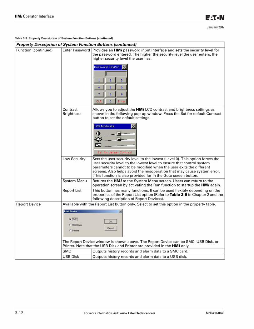
HMi Operator Interface
January 2007
Function (continued) Enter Password Provides an HMi password input interface and sets the security level for the password entered. The higher the security level the user enters, the higher security level the user has.
ContrastBrightness
Allows you to adjust the HMi LCD contrast and brightness settings as shown in the following pop-up window. Press the Set for default Contrast button to set the default settings.
Low Security Sets the user security level to the lowest (Level 0). This option forces the user security level to the lowest level to ensure that control system parameters cannot to be modified when the user exits the different screens. Also helps avoid the misoperation that may cause system error. (This function is also provided for in the Goto screen button.)
System Menu Returns the HMi to the System Menu screen. Users can return to the operation screen by activating the Run function to startup the HMi again.
Report List This button has many functions. It can be used flexibly depending on the properties of the Report List option (Refer to Table 2-9 in Chapter 2 and the following description of Report Devices).
Report Device Available with the Report List button only. Select to set this option in the property table.
The Report Device window is shown above. The Report Device can be SMC, USB Disk, or Printer. Note that the USB Disk and Printer are provided in the HMi only. SMC Outputs history records and alarm data to a SMC card.USB Disk Outputs history records and alarm data to a USB disk.
Table 3-9: Property Description of System Function Buttons (continued)
Property Description of System Function Buttons (continued)
3-12 For more information visit: www.EatonElectrical.com MN04802014E
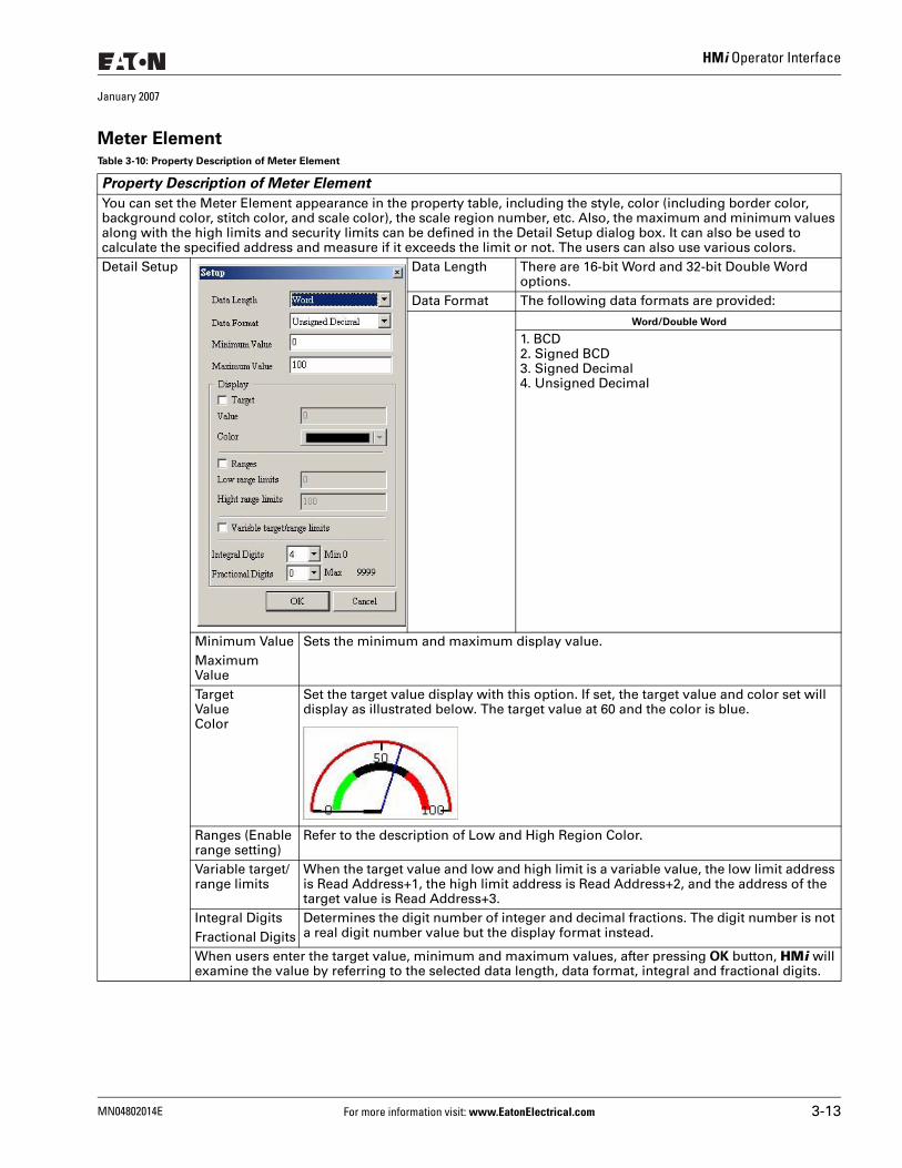
HMi Operator Interface
January 2007
Meter ElementTable 3-10: Property Description of Meter Element
Property Description of Meter Element
You can set the Meter Element appearance in the property table, including the style, color (including border color, background color, stitch color, and scale color), the scale region number, etc. Also, the maximum and minimum values along with the high limits and security limits can be defined in the Detail Setup dialog box. It can also be used to calculate the specified address and measure if it exceeds the limit or not. The users can also use various colors.Detail Setup Data Length There are 16-bit Word and 32-bit Double Word
options.Data Format The following data formats are provided:
Word/Double Word
1. BCD2. Signed BCD3. Signed Decimal4. Unsigned Decimal
Minimum Value Sets the minimum and maximum display value.Maximum ValueTargetValueColor
Set the target value display with this option. If set, the target value and color set will display as illustrated below. The target value at 60 and the color is blue.
Ranges (Enable range setting)
Refer to the description of Low and High Region Color.
Variable target/range limits
When the target value and low and high limit is a variable value, the low limit address is Read Address+1, the high limit address is Read Address+2, and the address of the target value is Read Address+3.
Integral Digits Determines the digit number of integer and decimal fractions. The digit number is not a real digit number value but the display format instead.Fractional Digits
When users enter the target value, minimum and maximum values, after pressing OK button, HMi will examine the value by referring to the selected data length, data format, integral and fractional digits.
MN04802014E For more information visit: www.EatonElectrical.com 3-13
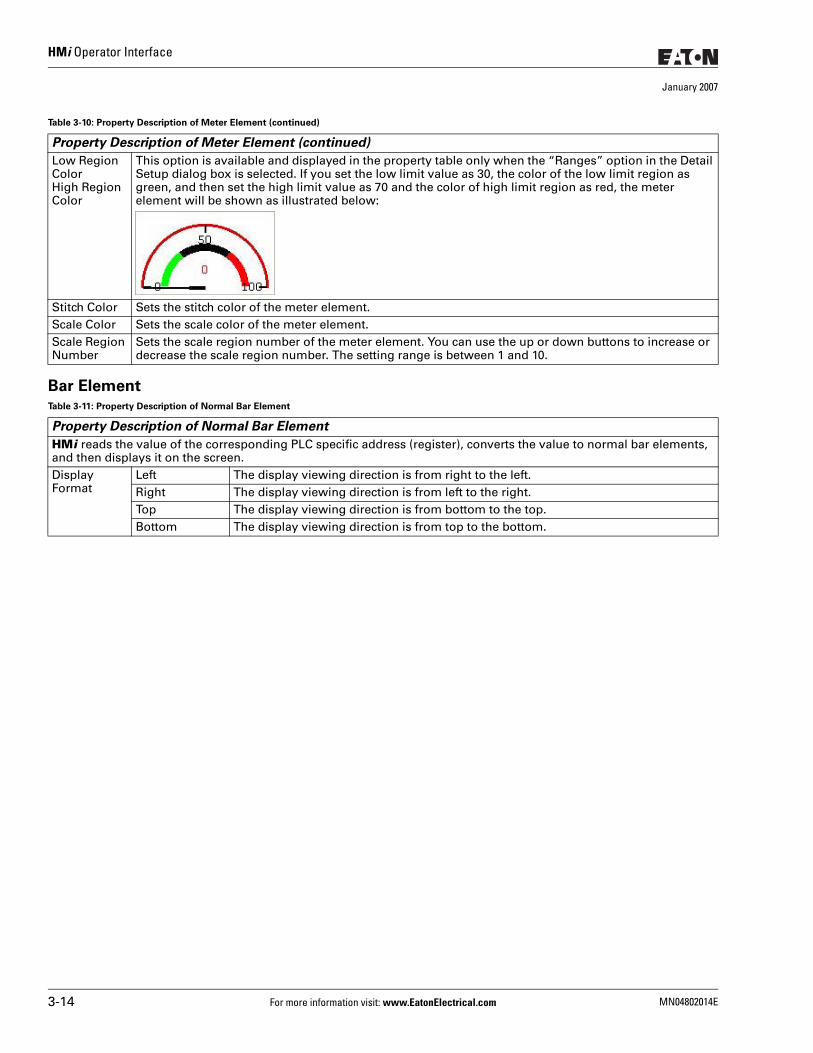
HMi Operator Interface
January 2007
Bar Element
Low Region ColorHigh Region Color
This option is available and displayed in the property table only when the “Ranges” option in the Detail Setup dialog box is selected. If you set the low limit value as 30, the color of the low limit region as green, and then set the high limit value as 70 and the color of high limit region as red, the meter element will be shown as illustrated below:
Stitch Color Sets the stitch color of the meter element.Scale Color Sets the scale color of the meter element.Scale Region Number
Sets the scale region number of the meter element. You can use the up or down buttons to increase or decrease the scale region number. The setting range is between 1 and 10.
Table 3-11: Property Description of Normal Bar Element
Property Description of Normal Bar Element
HMi reads the value of the corresponding PLC specific address (register), converts the value to normal bar elements, and then displays it on the screen. Display Format
Left The display viewing direction is from right to the left.Right The display viewing direction is from left to the right.Top The display viewing direction is from bottom to the top.Bottom The display viewing direction is from top to the bottom.
Table 3-10: Property Description of Meter Element (continued)
Property Description of Meter Element (continued)
3-14 For more information visit: www.EatonElectrical.com MN04802014E
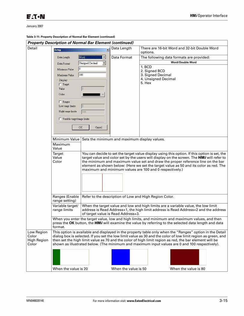
HMi Operator Interface
January 2007
Detail Data Length There are 16-bit Word and 32-bit Double Word options.
Data Format The following data formats are provided:Word/Double Word
1. BCD2. Signed BCD3. Signed Decimal4. Unsigned Decimal5. Hex
Minimum Value Sets the minimum and maximum display values.Maximum ValueTargetValueColor
You can decide to set the target value display using this option. If this option is set, the target value and color set by the users will display on the screen. The HMi will refer to the minimum and maximum value set and draw the proper reference line on the bar element as shown below: (Here we set the target value as 50 and its color as red. The maximum and minimum values are 100 and 0 respectively.)
Ranges (Enable range setting)
Refer to the description of Low and High Region Color.
Variable target/range limits
When the target value and low and high limits are a variable value, the low limit address is Read Address+1, the high limit address is Read Address+2 and the address of target value is Read Address+3.
When you enter the target value, low and high limits, and minimum and maximum values, and then press the OK button, the HMi will examine the value by referring to the selected data length and data format.
Low Region ColorHigh Region Color
This option is available and displayed in the property table only when the “Ranges” option in the Detail dialog box is selected. If you set the low limit value as 30 and the color of low limit region as green, and then set the high limit value as 70 and the color of high limit region as red, the bar element will be shown as illustrated below. (The minimum and maximum input values are 0 and 100 respectively).
When the value is 20 When the value is 50 When the value is 80
Table 3-11: Property Description of Normal Bar Element (continued)
Property Description of Normal Bar Element (continued)
MN04802014E For more information visit: www.EatonElectrical.com 3-15
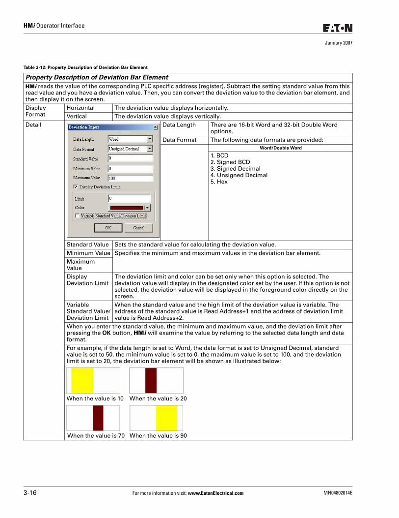
HMi Operator Interface
January 2007
Table 3-12: Property Description of Deviation Bar Element
Property Description of Deviation Bar Element
HMi reads the value of the corresponding PLC specific address (register). Subtract the setting standard value from this read value and you have a deviation value. Then, you can convert the deviation value to the deviation bar element, and then display it on the screen.Display Format
Horizontal The deviation value displays horizontally. Vertical The deviation value displays vertically.
Detail Data Length There are 16-bit Word and 32-bit Double Word options.
Data Format The following data formats are provided:Word/Double Word
1. BCD2. Signed BCD3. Signed Decimal4. Unsigned Decimal5. Hex
Standard Value Sets the standard value for calculating the deviation value.Minimum Value Specifies the minimum and maximum values in the deviation bar element.Maximum ValueDisplay Deviation Limit
The deviation limit and color can be set only when this option is selected. The deviation value will display in the designated color set by the user. If this option is not selected, the deviation value will be displayed in the foreground color directly on the screen.
Variable Standard Value/Deviation Limit
When the standard value and the high limit of the deviation value is variable. The address of the standard value is Read Address+1 and the address of deviation limit value is Read Address+2.
When you enter the standard value, the minimum and maximum value, and the deviation limit after pressing the OK button, HMi will examine the value by referring to the selected data length and data format.For example, if the data length is set to Word, the data format is set to Unsigned Decimal, standard value is set to 50, the minimum value is set to 0, the maximum value is set to 100, and the deviation limit is set to 20, the deviation bar element will be shown as illustrated below:
When the value is 10 When the value is 20
When the value is 70 When the value is 90
3-16 For more information visit: www.EatonElectrical.com MN04802014E
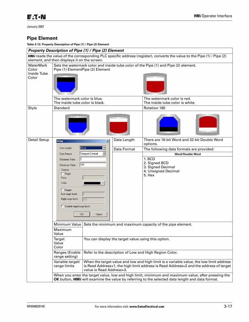
HMi Operator Interface
January 2007
Pipe ElementTable 3-13: Property Description of Pipe (1) / Pipe (2) Element
Property Description of Pipe (1) / Pipe (2) Element
HMi reads the value of the corresponding PLC specific address (register), converts the value to the Pipe (1) / Pipe (2) element, and then displays it on the screen. WaterMark ColorInside Tube Color
Sets the watermark color and inside tube color of the Pipe (1) and Pipe (2) element.Pipe (1) ElementPipe (2) Element
The watermark color is blue.The inside tube color is black.
The watermark color is red.The inside tube color is white.
Style Standard Rotation 180
Detail Setup Data Length There are 16-bit Word and 32-bit Double Word options.
Data Format The following data formats are provided:Word/Double Word
1. BCD2. Signed BCD3. Signed Decimal4. Unsigned Decimal5. Hex
Minimum Value Sets the minimum and maximum capacity of the pipe element.Maximum ValueTargetValueColor
You can display the target value using this option.
Ranges (Enable range setting)
Refer to the description of Low and High Region Color.
Variable target/range limits
When the target value and low and high limit is a variable value, the low limit address is Read Address+1, the high limit address is Read Address+2 and the address of target value is Read Address+3.
When you enter the target value, low and high limit, minimum and maximum value, after pressing the OK button, HMi will examine the value by referring to the selected data length and data format.
MN04802014E For more information visit: www.EatonElectrical.com 3-17
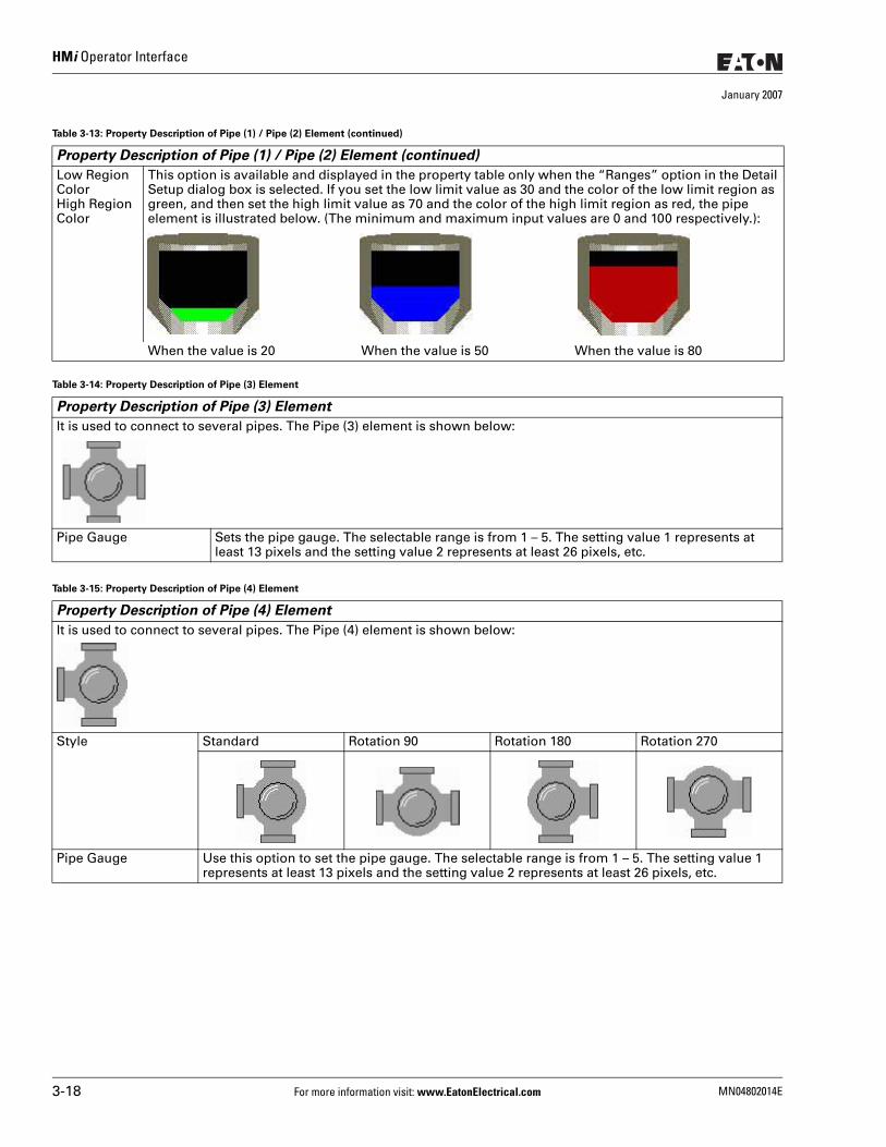
HMi Operator Interface
January 2007
Low Region ColorHigh Region Color
This option is available and displayed in the property table only when the “Ranges” option in the Detail Setup dialog box is selected. If you set the low limit value as 30 and the color of the low limit region as green, and then set the high limit value as 70 and the color of the high limit region as red, the pipe element is illustrated below. (The minimum and maximum input values are 0 and 100 respectively.):
When the value is 20 When the value is 50 When the value is 80
Table 3-14: Property Description of Pipe (3) Element
Property Description of Pipe (3) Element
It is used to connect to several pipes. The Pipe (3) element is shown below:
Pipe Gauge Sets the pipe gauge. The selectable range is from 1 – 5. The setting value 1 represents at least 13 pixels and the setting value 2 represents at least 26 pixels, etc.
Table 3-15: Property Description of Pipe (4) Element
Property Description of Pipe (4) Element
It is used to connect to several pipes. The Pipe (4) element is shown below:
Style Standard Rotation 90 Rotation 180 Rotation 270
Pipe Gauge Use this option to set the pipe gauge. The selectable range is from 1 – 5. The setting value 1 represents at least 13 pixels and the setting value 2 represents at least 26 pixels, etc.
Table 3-13: Property Description of Pipe (1) / Pipe (2) Element (continued)
Property Description of Pipe (1) / Pipe (2) Element (continued)
3-18 For more information visit: www.EatonElectrical.com MN04802014E
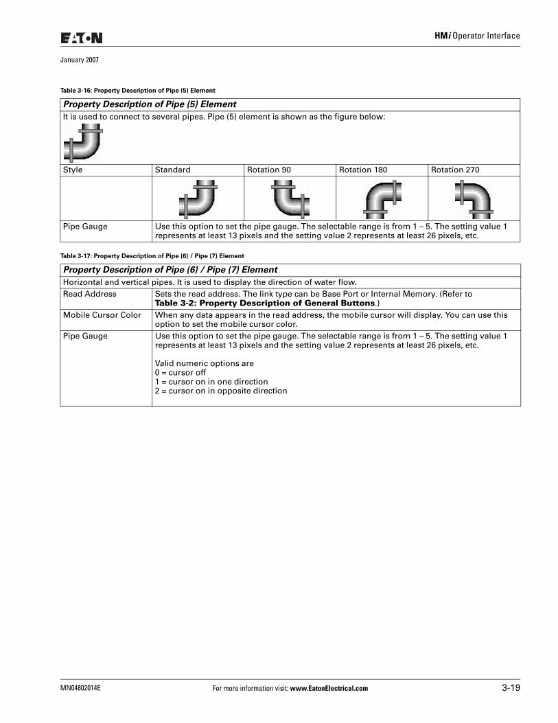
HMi Operator Interface
January 2007
Table 3-16: Property Description of Pipe (5) Element
Property Description of Pipe (5) Element
It is used to connect to several pipes. Pipe (5) element is shown as the figure below:
Style Standard Rotation 90 Rotation 180 Rotation 270
Pipe Gauge Use this option to set the pipe gauge. The selectable range is from 1 – 5. The setting value 1 represents at least 13 pixels and the setting value 2 represents at least 26 pixels, etc.
Table 3-17: Property Description of Pipe (6) / Pipe (7) Element
Property Description of Pipe (6) / Pipe (7) Element
Horizontal and vertical pipes. It is used to display the direction of water flow. Read Address Sets the read address. The link type can be Base Port or Internal Memory. (Refer to
Table 3-2: Property Description of General Buttons.)Mobile Cursor Color When any data appears in the read address, the mobile cursor will display. You can use this
option to set the mobile cursor color. Pipe Gauge Use this option to set the pipe gauge. The selectable range is from 1 – 5. The setting value 1
represents at least 13 pixels and the setting value 2 represents at least 26 pixels, etc.
Valid numeric options are0 = cursor off1 = cursor on in one direction2 = cursor on in opposite direction
MN04802014E For more information visit: www.EatonElectrical.com 3-19
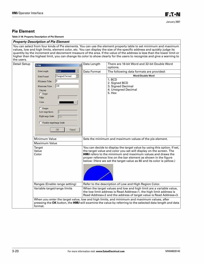
HMi Operator Interface
January 2007
Pie Element
Table 3-18: Property Description of Pie Element
Property Description of Pie Element
You can select from four kinds of Pie elements. You can use the element property table to set minimum and maximum values, low and high limits, element color, etc. You can display the size of the specific address and quickly judge its quantity by the increment and decrement measure of the area. If the value of the address is less than the lower limit or higher than the highest limit, you can change its color to show clearly for the users to recognize and give a warning to the users. Detail Setup Data Length There are 16-bit Word and 32-bit Double Word
options.Data Format The following data formats are provided:
Word/Double Word
1. BCD2. Signed BCD3. Signed Decimal4. Unsigned Decimal5. Hex
Minimum Value Sets the minimum and maximum values of the pie element.Maximum ValueTargetValueColor
You can decide to display the target value by using this option. If set, the target value and color you set will display on the screen. The HMi refers to the minimum and maximum values and draws the proper reference line on the bar element as shown in the figure below: (Here we set the target value as 80 and its color is yellow.)
Ranges (Enable range setting) Refer to the description of Low and High Region Color.Variable target/range limits When the target values and low and high limit are a variable value,
the low limit address is Read Address+1, the high limit address is Read Address+2 and the address of target value is Read Address+3.
When you enter the target value, low and high limits, and minimum and maximum values, after pressing the OK button, the HMi will examine the value by referring to the selected data length and data format.
3-20 For more information visit: www.EatonElectrical.com MN04802014E
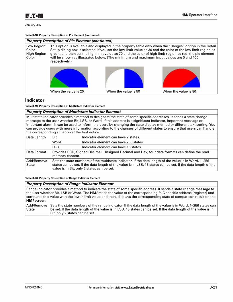
HMi Operator Interface
January 2007
Indicator
Low Region ColorHigh Region Color
This option is available and displayed in the property table only when the “Ranges” option in the Detail Setup dialog box is selected. If you set the low limit value as 30 and the color of the low limit region as green, and then set the high limit value as 70 and the color of high limit region as red, the pie element will be shown as illustrated below: (The minimum and maximum input values are 0 and 100 respectively.)
When the value is 20 When the value is 50 When the value is 80
Table 3-19: Property Description of Multistate Indicator Element
Property Description of Multistate Indicator Element
Multistate indicator provides a method to designate the state of some specific addresses. It sends a state change message to the user whether Bit, LSB, or Word. If this address is a significant indicator, important message or important alarm, it can be used to inform the users by changing the state display method or different text setting. You can provide users with more information according to the changes of different states to ensure that users can handle the corresponding situation at the first notice.Data Length Bit Indicator element can have 2 states.
Word Indicator element can have 256 states.LSB Indicator element can have 16 states.
Data Format Provides BCD, Signed Decimal, Unsigned Decimal and Hex; four data formats can define the read memory content.
Add/Remove State
Sets the state numbers of the multistate indicator. If the data length of the value is in Word, 1–256 states can be set. If the data length of the value is in LSB, 16 states can be set. If the data length of the value is in Bit, only 2 states can be set.
Table 3-20: Property Description of Range Indicator Element
Property Description of Range Indicator Element
Range indicator provides a method to indicate the state of some specific address. It sends a state change message to the user whether Bit, LSB or Word. The HMi reads the value of the corresponding PLC specific address (register) and compares this value with the lower limit value and then, displays the corresponding state of comparison result on the HMi screen.Add/Remove State
Sets the state numbers of the range indicator. If the data length of the value is in Word, 1–256 states can be set. If the data length of the value is in LSB, 16 states can be set. If the data length of the value is in Bit, only 2 states can be set.
Table 3-18: Property Description of Pie Element (continued)
Property Description of Pie Element (continued)
MN04802014E For more information visit: www.EatonElectrical.com 3-21
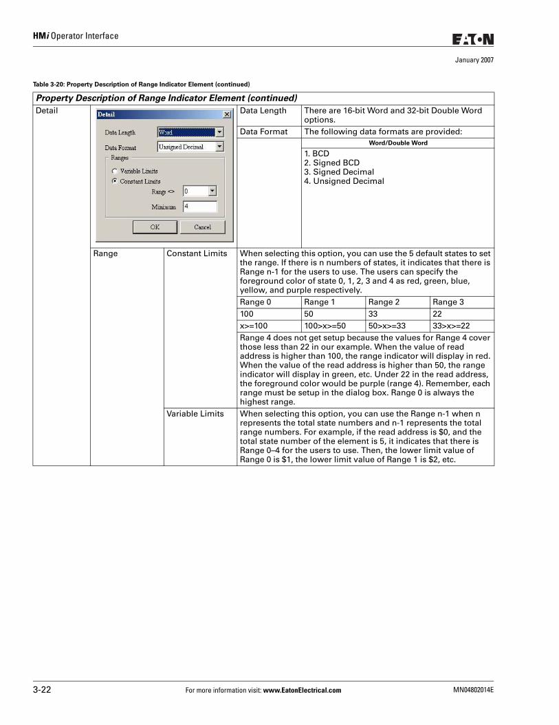
HMi Operator Interface
January 2007
Detail Data Length There are 16-bit Word and 32-bit Double Word options.
Data Format The following data formats are provided:Word/Double Word
1. BCD2. Signed BCD3. Signed Decimal4. Unsigned Decimal
Range Constant Limits When selecting this option, you can use the 5 default states to set the range. If there is n numbers of states, it indicates that there is Range n-1 for the users to use. The users can specify the foreground color of state 0, 1, 2, 3 and 4 as red, green, blue, yellow, and purple respectively.Range 0 Range 1 Range 2 Range 3100 50 33 22x>=100 100>x>=50 50>x>=33 33>x>=22Range 4 does not get setup because the values for Range 4 cover those less than 22 in our example. When the value of read address is higher than 100, the range indicator will display in red. When the value of the read address is higher than 50, the range indicator will display in green, etc. Under 22 in the read address, the foreground color would be purple (range 4). Remember, each range must be setup in the dialog box. Range 0 is always the highest range.
Variable Limits When selecting this option, you can use the Range n-1 when n represents the total state numbers and n-1 represents the total range numbers. For example, if the read address is $0, and the total state number of the element is 5, it indicates that there is Range 0–4 for the users to use. Then, the lower limit value of Range 0 is $1, the lower limit value of Range 1 is $2, etc.
Table 3-20: Property Description of Range Indicator Element (continued)
Property Description of Range Indicator Element (continued)
3-22 For more information visit: www.EatonElectrical.com MN04802014E
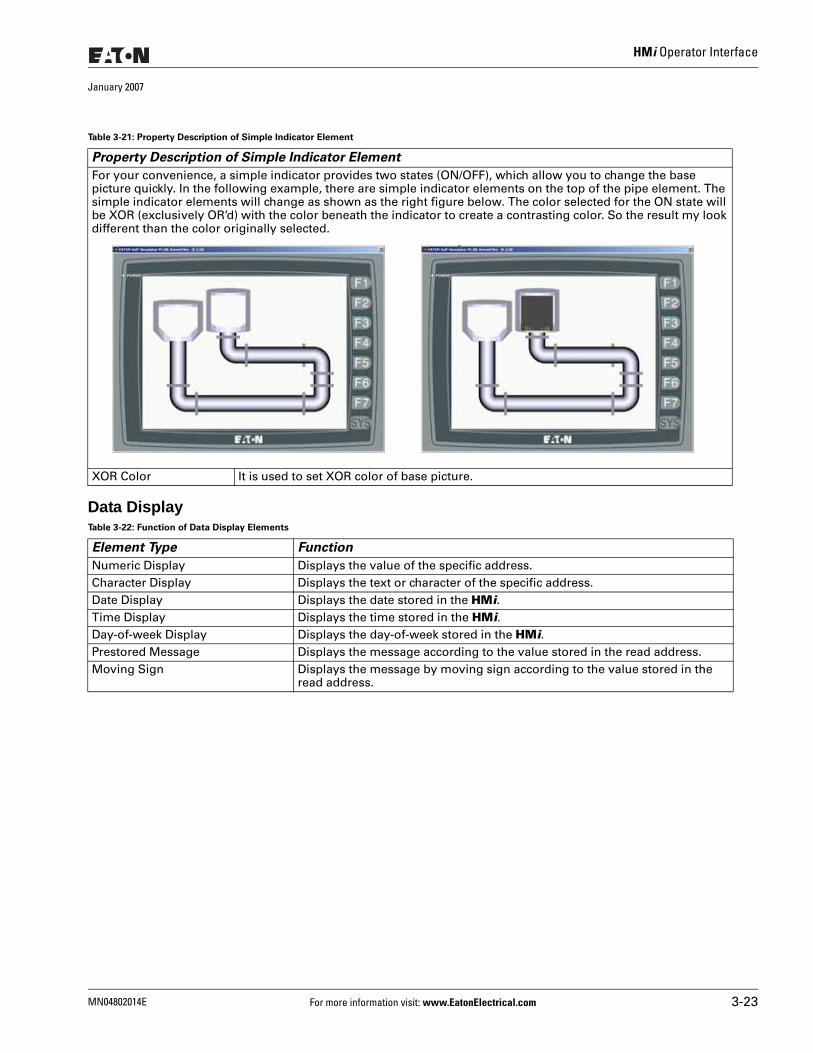
HMi Operator Interface
January 2007
Data Display
Table 3-21: Property Description of Simple Indicator Element
Property Description of Simple Indicator Element
For your convenience, a simple indicator provides two states (ON/OFF), which allow you to change the base picture quickly. In the following example, there are simple indicator elements on the top of the pipe element. The simple indicator elements will change as shown as the right figure below. The color selected for the ON state will be XOR (exclusively OR’d) with the color beneath the indicator to create a contrasting color. So the result my look different than the color originally selected.
XOR Color It is used to set XOR color of base picture.
Table 3-22: Function of Data Display Elements
Element Type Function
Numeric Display Displays the value of the specific address. Character Display Displays the text or character of the specific address. Date Display Displays the date stored in the HMi.Time Display Displays the time stored in the HMi.Day-of-week Display Displays the day-of-week stored in the HMi.Prestored Message Displays the message according to the value stored in the read address.Moving Sign Displays the message by moving sign according to the value stored in the
read address.
MN04802014E For more information visit: www.EatonElectrical.com 3-23
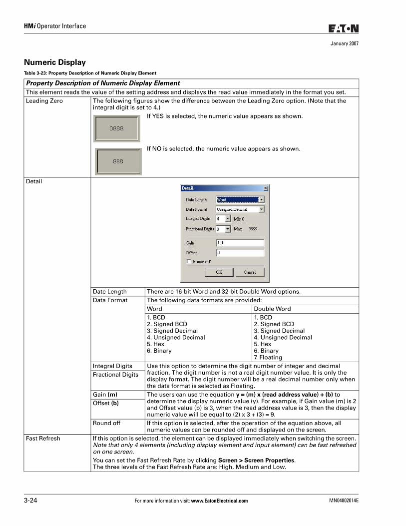
HMi Operator Interface
January 2007
Numeric Display
Table 3-23: Property Description of Numeric Display Element
Property Description of Numeric Display Element
This element reads the value of the setting address and displays the read value immediately in the format you set.Leading Zero The following figures show the difference between the Leading Zero option. (Note that the
integral digit is set to 4.)If YES is selected, the numeric value appears as shown.
If NO is selected, the numeric value appears as shown.
Detail
Date Length There are 16-bit Word and 32-bit Double Word options.Data Format The following data formats are provided:
Word Double Word1. BCD2. Signed BCD3. Signed Decimal4. Unsigned Decimal5. Hex6. Binary
1. BCD2. Signed BCD3. Signed Decimal4. Unsigned Decimal5. Hex6. Binary7. Floating
Integral Digits Use this option to determine the digit number of integer and decimal fraction. The digit number is not a real digit number value. It is only the display format. The digit number will be a real decimal number only when the data format is selected as Floating.
Fractional Digits
Gain (m) The users can use the equation y = (m) x (read address value) + (b) to determine the display numeric value (y). For example, if Gain value (m) is 2 and Offset value (b) is 3, when the read address value is 3, then the display numeric value will be equal to (2) x 3 + (3) = 9.
Offset (b)
Round off If this option is selected, after the operation of the equation above, all numeric values can be rounded off and displayed on the screen.
Fast Refresh If this option is selected, the element can be displayed immediately when switching the screen. Note that only 4 elements (including display element and input element) can be fast refreshed on one screen.You can set the Fast Refresh Rate by clicking Screen > Screen Properties.The three levels of the Fast Refresh Rate are: High, Medium and Low.
3-24 For more information visit: www.EatonElectrical.com MN04802014E
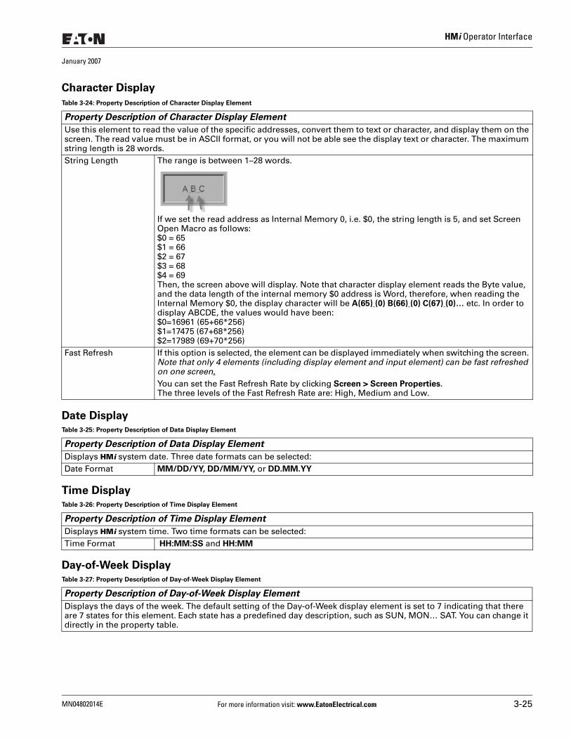
HMi Operator Interface
January 2007
Character Display
Date Display
Time Display
Day-of-Week Display
Table 3-24: Property Description of Character Display Element
Property Description of Character Display Element
Use this element to read the value of the specific addresses, convert them to text or character, and display them on the screen. The read value must be in ASCII format, or you will not be able see the display text or character. The maximum string length is 28 words.String Length The range is between 1–28 words.
If we set the read address as Internal Memory 0, i.e. $0, the string length is 5, and set Screen Open Macro as follows: $0 = 65$1 = 66$2 = 67$3 = 68$4 = 69Then, the screen above will display. Note that character display element reads the Byte value, and the data length of the internal memory $0 address is Word, therefore, when reading the Internal Memory $0, the display character will be A(65) (0) B(66) (0) C(67) (0)… etc. In order to display ABCDE, the values would have been:$0=16961 (65+66*256)$1=17475 (67+68*256)$2=17989 (69+70*256)
Fast Refresh If this option is selected, the element can be displayed immediately when switching the screen. Note that only 4 elements (including display element and input element) can be fast refreshed on one screen. You can set the Fast Refresh Rate by clicking Screen > Screen Properties.The three levels of the Fast Refresh Rate are: High, Medium and Low.
Table 3-25: Property Description of Data Display Element
Property Description of Data Display Element
Displays HMi system date. Three date formats can be selected: Date Format MM/DD/YY, DD/MM/YY, or DD.MM.YY
Table 3-26: Property Description of Time Display Element
Property Description of Time Display Element
Displays HMi system time. Two time formats can be selected: Time Format HH:MM:SS and HH:MM
Table 3-27: Property Description of Day-of-Week Display Element
Property Description of Day-of-Week Display Element
Displays the days of the week. The default setting of the Day-of-Week display element is set to 7 indicating that there are 7 states for this element. Each state has a predefined day description, such as SUN, MON… SAT. You can change it directly in the property table.
MN04802014E For more information visit: www.EatonElectrical.com 3-25
HMi Operator Interface
January 2007
Prestored Message
Moving Sign
Table 3-28: Property Description of Prestored Message Element
Property Description of Prestored Message Element
Displays the state content of the corresponding PLC contact or register directly. You can set the number and text for each state. The element is perfect for decoding fault codes in drives, PLCs, etc. Simply designate the fault code address as the read address then assign the fault code text to the fault code value.Data Type Bit Has two states.
Word Has 256 states.LSB Has 16 states.
Data Format Provides four kinds of data format to define the read memory content, including: BCD, Signed Decimal, Unsigned Decimal, and Hex.
Add/Remove State Sets the state numbers of prestored message elements. If the data length of the value is in Word, 1–256 states can be set. If the data length of the value is in LSB, 16 states can be set. If the data length of the value is in Bit, only 2 states can be set.
Table 3-29: Property Description of Moving Sign Element
Property Description of Moving Sign Element
A Moving Sign is one that uses movement, lighting, or special display to depict and display the state content of the corresponding PLC contact or register. You can determine the display of the moving sign by setting the direction, moving points, and interval (ms) in the property table.Data Type Bit Can have two states.
Word Can have 256 states.LSB Can have 16 states.
Data Format Provides four kinds of data formats to define the read memory content, including: BCD, Signed Decimal, Unsigned Decimal, and Hex.
Add/Remove State Sets the state numbers of the moving sign element. If the data length of the value is in Word, 1–256 states can be set. If the data length of the value is in LSB, 16 states can be set. If the data length of the value is in Bit, only 2 states can be set.
Direction Left Viewed from right to the left.Right Viewed from left to the right.Top Viewed from bottom to the top.Bottom Viewed from top to the bottom.
Moving Points Sets the movement of the moving sign. The unit is Pixel and the range is between 1 – 50 Pixels.Interval time) Sets the interval time between two movements. The unit is ms and the range is between 50 –
3000 ms.
3-26 For more information visit: www.EatonElectrical.com MN04802014E
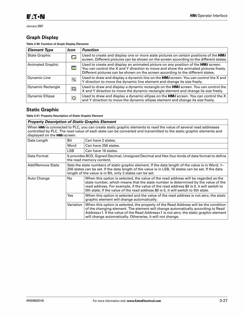
HMi Operator Interface
January 2007
Graph Display
Static Graphic
Table 3-30: Function of Graph Display Elements
Element Type Icon Function
State Graphic Used to create and display one or more state pictures on certain positions of the HMi screen. Different pictures can be shown on the screen according to the different states.
Animated Graphic Used to create and display an animated picture on any position of the HMi screen. You can control the X and Y direction to move and show the animated pictures freely. Different pictures can be shown on the screen according to the different states.
Dynamic Line Used to draw and display a dynamic line on the HMi screen. You can control the X and Y direction to move the dynamic line element and change its size freely.
Dynamic Rectangle Used to draw and display a dynamic rectangle on the HMi screen. You can control the X and Y direction to move the dynamic rectangle element and change its size freely.
Dynamic Ellipse Used to draw and display a dynamic ellipse on the HMi screen. You can control the X and Y direction to move the dynamic ellipse element and change its size freely.
Table 3-31: Property Description of Static Graphic Element
Property Description of Static Graphic Element
When HMi is connected to PLC, you can create static graphic elements to read the value of several read addresses controlled by PLC. The read value of each state can be converted and transmitted to the static graphic elements and displayed on the HMi screen. Data Length Bit Can have 2 states.
Word Can have 256 states.LSB Can have 16 states.
Data Format It provides BCD, Signed Decimal, Unsigned Decimal and Hex four kinds of data format to define the read memory content.
Add/Remove State Sets the state numbers of static graphic element. If the data length of the value is in Word, 1–256 states can be set. If the data length of the value is in LSB, 16 states can be set. If the data length of the value is in Bit, only 2 states can be set.
Auto Change No When this option is selected, the value of the read address will be regarded as the state number, which means that the state number is determined by the value of the read address. For example, if the value of the read address $0 is 0, it will switch to 0th state; if the value of the read address $0 is 5, it will switch to 5th state.
Yes When this option is selected and the value of the read address is not zero, the static graphic element will change automatically.
Variation When this option is selected, the property of the Read Address will be the condition of the changing element. The element will change automatically according to Read Address+1. If the value of the Read Address+1 is not zero, the static graphic element will change automatically. Otherwise, it will not change.
MN04802014E For more information visit: www.EatonElectrical.com 3-27
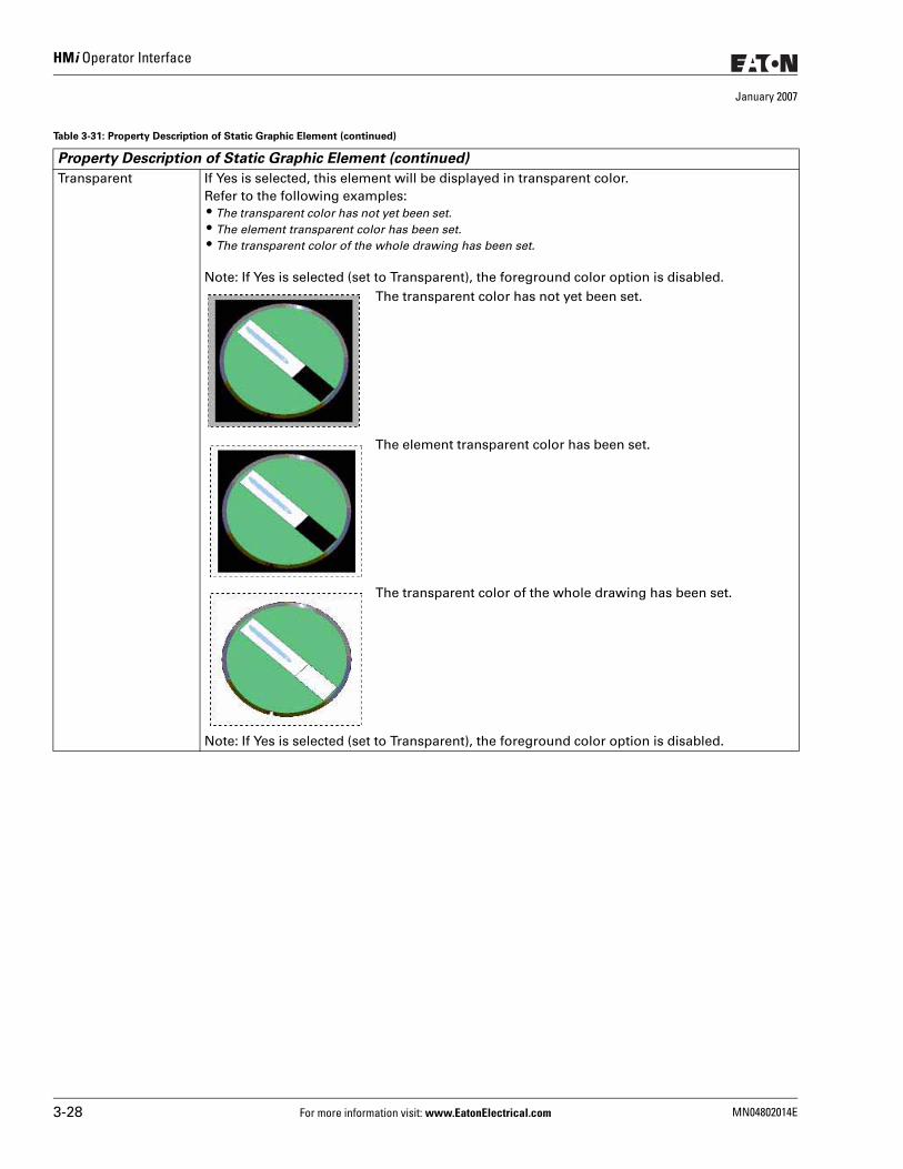
HMi Operator Interface
January 2007
Transparent If Yes is selected, this element will be displayed in transparent color. Refer to the following examples: ● The transparent color has not yet been set. ● The element transparent color has been set. ● The transparent color of the whole drawing has been set.
Note: If Yes is selected (set to Transparent), the foreground color option is disabled.The transparent color has not yet been set.
The element transparent color has been set.
The transparent color of the whole drawing has been set.
Note: If Yes is selected (set to Transparent), the foreground color option is disabled.
Table 3-31: Property Description of Static Graphic Element (continued)
Property Description of Static Graphic Element (continued)
3-28 For more information visit: www.EatonElectrical.com MN04802014E
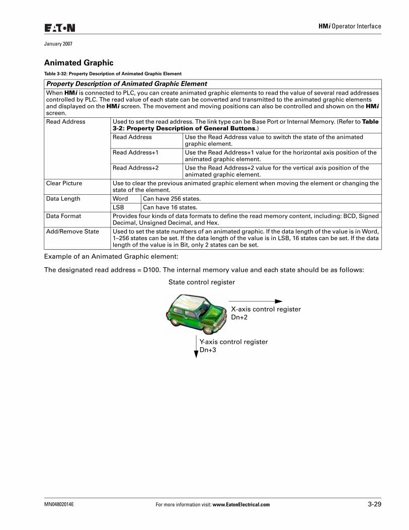
HMi Operator Interface
January 2007
Animated Graphic
Example of an Animated Graphic element:
The designated read address = D100. The internal memory value and each state should be as follows:
Table 3-32: Property Description of Animated Graphic Element
Property Description of Animated Graphic Element
When HMi is connected to PLC, you can create animated graphic elements to read the value of several read addresses controlled by PLC. The read value of each state can be converted and transmitted to the animated graphic elements and displayed on the HMi screen. The movement and moving positions can also be controlled and shown on the HMi screen.Read Address Used to set the read address. The link type can be Base Port or Internal Memory. (Refer to Table
3-2: Property Description of General Buttons.) Read Address Use the Read Address value to switch the state of the animated
graphic element. Read Address+1 Use the Read Address+1 value for the horizontal axis position of the
animated graphic element.Read Address+2 Use the Read Address+2 value for the vertical axis position of the
animated graphic element.Clear Picture Use to clear the previous animated graphic element when moving the element or changing the
state of the element.Data Length Word Can have 256 states.
LSB Can have 16 states. Data Format Provides four kinds of data formats to define the read memory content, including: BCD, Signed
Decimal, Unsigned Decimal, and Hex.Add/Remove State Used to set the state numbers of an animated graphic. If the data length of the value is in Word,
1–256 states can be set. If the data length of the value is in LSB, 16 states can be set. If the data length of the value is in Bit, only 2 states can be set.
X-axis control register Dn+2
Y-axis control register Dn+3
State control register
MN04802014E For more information visit: www.EatonElectrical.com 3-29
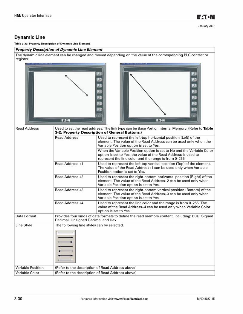
HMi Operator Interface
January 2007
Dynamic Line
Table 3-33: Property Description of Dynamic Line Element
Property Description of Dynamic Line Element
The dynamic line element can be changed and moved depending on the value of the corresponding PLC contact or register.
Read Address Used to set the read address. The link type can be Base Port or Internal Memory. (Refer to Table 3-2: Property Description of General Buttons.) Read Address Used to represent the left-top horizontal position (Left) of the
element. The value of the Read Address can be used only when the Variable Position option is set to Yes.When the Variable Position option is set to No and the Variable Color option is set to Yes, the value of the Read Address is used to represent the line color and the range is from 0–255.
Read Address +1 Used to represent the left-top vertical position (Top) of the element. The value of the Read Address+1 can be used only when Variable Position option is set to Yes.
Read Address +2 Used to represent the right-bottom horizontal position (Right) of the element. The value of the Read Address+2 can be used only when Variable Position option is set to Yes.
Read Address +3 Used to represent the right-bottom vertical position (Bottom) of the element. The value of the Read Address+3 can be used only when Variable Position option is set to Yes.
Read Address +4 Used to represent the line color and the range is from 0–255. The value of the Read Address+4 can be used only when Variable Color option is set to Yes.
Data Format Provides four kinds of data formats to define the read memory content, including: BCD, Signed Decimal, Unsigned Decimal and Hex.
Line Style The following line styles can be selected.
Variable Position (Refer to the description of Read Address above)Variable Color (Refer to the description of Read Address above)
3-30 For more information visit: www.EatonElectrical.com MN04802014E
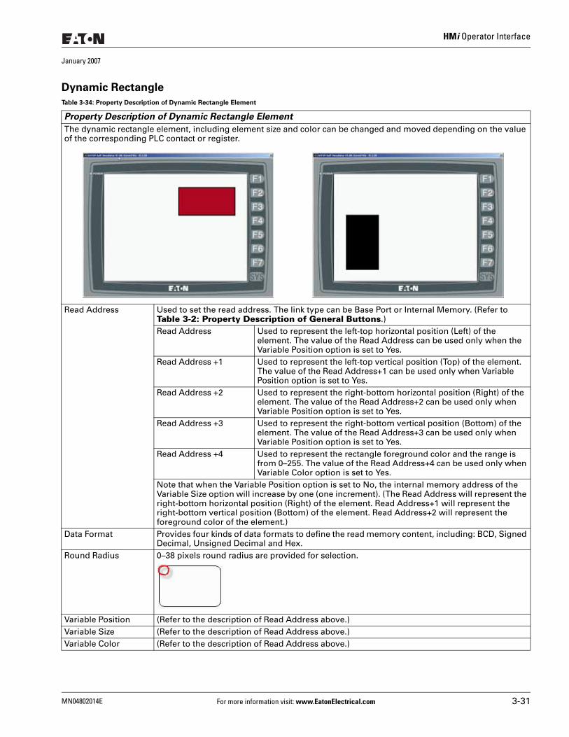
HMi Operator Interface
January 2007
Dynamic Rectangle
Table 3-34: Property Description of Dynamic Rectangle Element
Property Description of Dynamic Rectangle Element
The dynamic rectangle element, including element size and color can be changed and moved depending on the value of the corresponding PLC contact or register.
Read Address Used to set the read address. The link type can be Base Port or Internal Memory. (Refer to Table 3-2: Property Description of General Buttons.) Read Address Used to represent the left-top horizontal position (Left) of the
element. The value of the Read Address can be used only when the Variable Position option is set to Yes.
Read Address +1 Used to represent the left-top vertical position (Top) of the element. The value of the Read Address+1 can be used only when Variable Position option is set to Yes.
Read Address +2 Used to represent the right-bottom horizontal position (Right) of the element. The value of the Read Address+2 can be used only when Variable Position option is set to Yes.
Read Address +3 Used to represent the right-bottom vertical position (Bottom) of the element. The value of the Read Address+3 can be used only when Variable Position option is set to Yes.
Read Address +4 Used to represent the rectangle foreground color and the range is from 0–255. The value of the Read Address+4 can be used only when Variable Color option is set to Yes.
Note that when the Variable Position option is set to No, the internal memory address of the Variable Size option will increase by one (one increment). (The Read Address will represent the right-bottom horizontal position (Right) of the element. Read Address+1 will represent the right-bottom vertical position (Bottom) of the element. Read Address+2 will represent the foreground color of the element.)
Data Format Provides four kinds of data formats to define the read memory content, including: BCD, Signed Decimal, Unsigned Decimal and Hex.
Round Radius 0–38 pixels round radius are provided for selection.
Variable Position (Refer to the description of Read Address above.)Variable Size (Refer to the description of Read Address above.)Variable Color (Refer to the description of Read Address above.)
MN04802014E For more information visit: www.EatonElectrical.com 3-31
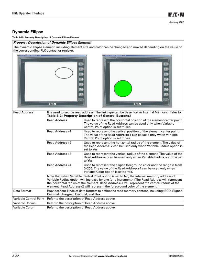
HMi Operator Interface
January 2007
Dynamic Ellipse
Table 3-35: Property Description of Dynamic Ellipse Element
Property Description of Dynamic Ellipse Element
The dynamic ellipse element, including element size and color can be changed and moved depending on the value of the corresponding PLC contact or register.
Read Address It is used to set the read address. The link type can be Base Port or Internal Memory. (Refer to Table 3-2: Property Description of General Buttons.) Read Address Used to represent the horizontal position of the element center point.
The value of the Read Address can be used only when Variable Central Point option is set to Yes.
Read Address +1 Used to represent the vertical position of the element center point. The value of the Read Address+1 can be used only when Variable Central Point option is set to Yes.
Read Address +2 Used to represent the horizontal radius of the element.The value of the Read Address+2 can be used only when Variable Radius option is set to Yes.
Read Address +3 Used to represent the vertical radius of the element. The value of the Read Address+3 can be used only when Variable Radius option is set to Yes.
Read Address +4 Used to represent the ellipse foreground color and the range is from 0–255. The value of the Read Address+4 can be used only when Variable Color option is set to Yes.
Note that when Variable Central Point option is set to No, the internal memory address of Variable Radius option will increase by one (one increment). (The Read Address will represent the horizontal radius of the element. Read Address+1 will represent the vertical radius of the element. Read Address+2 will represent the foreground color of the element.)
Data Format Provides four kinds of data formats to define the read memory content, including: BCD, Signed Decimal, Unsigned Decimal, and Hex.
Variable Central Point Refer to the description of Read Address above.Variable Radius Refer to the description of Read Address above.Variable Color Refer to the description of Read Address above.
3-32 For more information visit: www.EatonElectrical.com MN04802014E
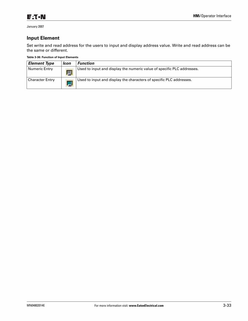
HMi Operator Interface
January 2007
Input Element
Set write and read address for the users to input and display address value. Write and read address can be the same or different.
Table 3-36: Function of Input Elements
Element Type Icon Function
Numeric Entry Used to input and display the numeric value of specific PLC addresses.
Character Entry Used to input and display the characters of specific PLC addresses.
MN04802014E For more information visit: www.EatonElectrical.com 3-33
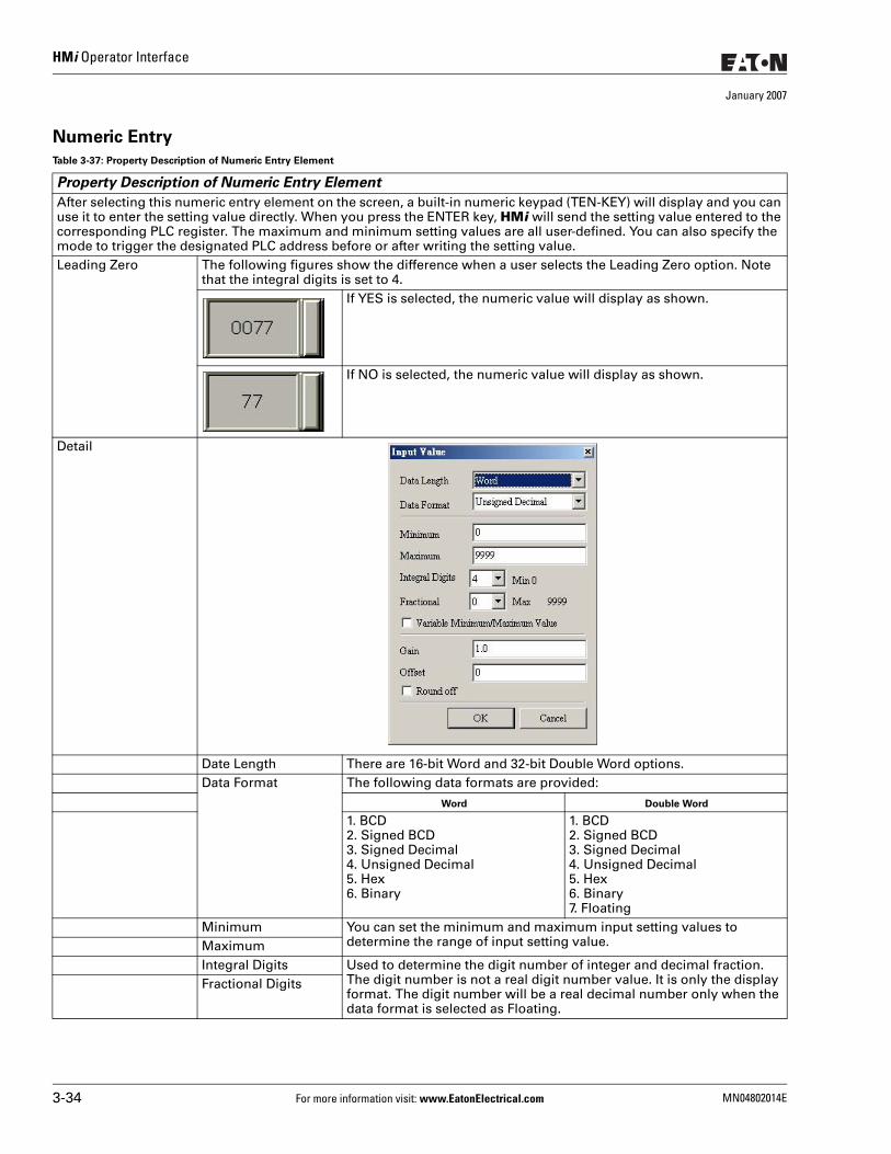
HMi Operator Interface
January 2007
Numeric Entry
Table 3-37: Property Description of Numeric Entry Element
Property Description of Numeric Entry Element
After selecting this numeric entry element on the screen, a built-in numeric keypad (TEN-KEY) will display and you can use it to enter the setting value directly. When you press the ENTER key, HMi will send the setting value entered to the corresponding PLC register. The maximum and minimum setting values are all user-defined. You can also specify the mode to trigger the designated PLC address before or after writing the setting value. Leading Zero The following figures show the difference when a user selects the Leading Zero option. Note
that the integral digits is set to 4.If YES is selected, the numeric value will display as shown.
If NO is selected, the numeric value will display as shown.
Detail
Date Length There are 16-bit Word and 32-bit Double Word options.Data Format The following data formats are provided:
Word Double Word
1. BCD2. Signed BCD3. Signed Decimal4. Unsigned Decimal5. Hex6. Binary
1. BCD2. Signed BCD3. Signed Decimal4. Unsigned Decimal5. Hex6. Binary7. Floating
Minimum You can set the minimum and maximum input setting values to determine the range of input setting value. Maximum
Integral Digits Used to determine the digit number of integer and decimal fraction. The digit number is not a real digit number value. It is only the display format. The digit number will be a real decimal number only when the data format is selected as Floating.
Fractional Digits
3-34 For more information visit: www.EatonElectrical.com MN04802014E
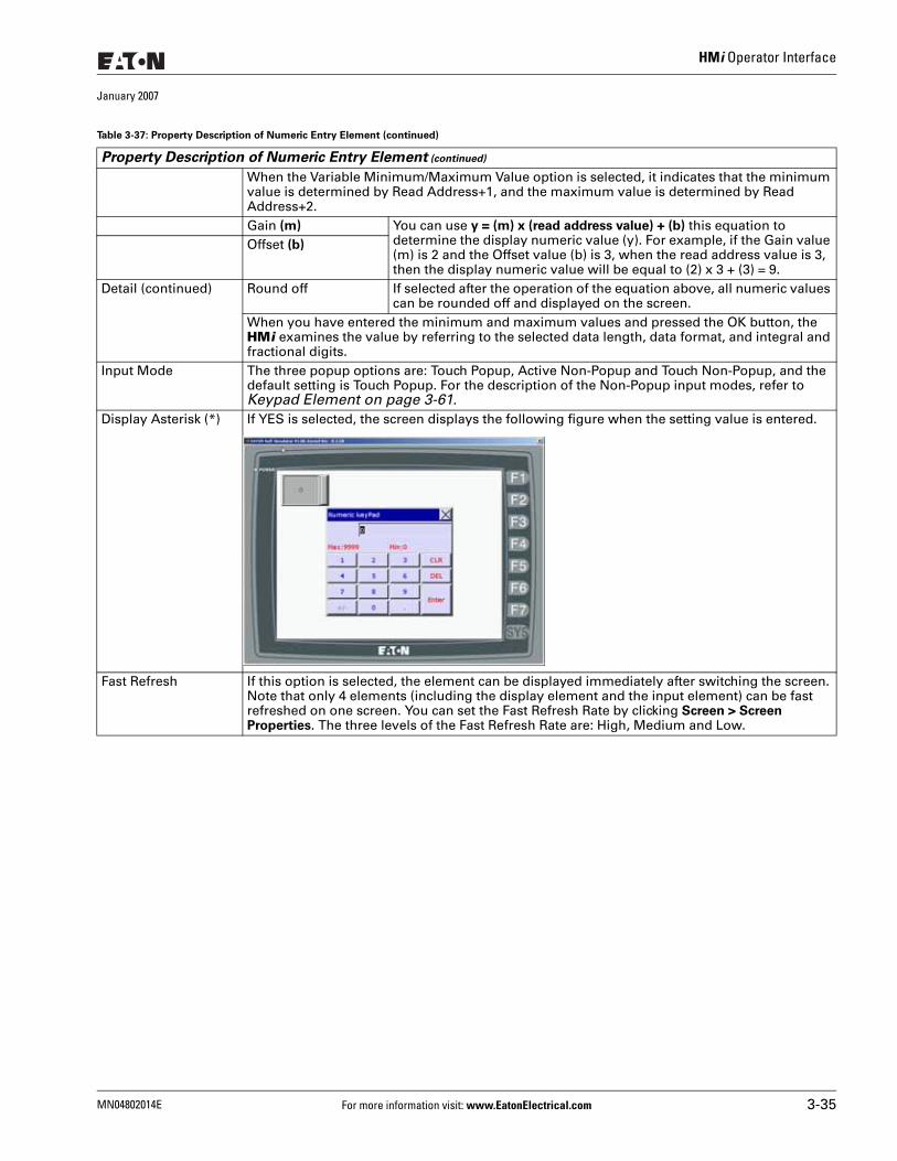
HMi Operator Interface
January 2007
When the Variable Minimum/Maximum Value option is selected, it indicates that the minimum value is determined by Read Address+1, and the maximum value is determined by Read Address+2.Gain (m) You can use y = (m) x (read address value) + (b) this equation to
determine the display numeric value (y). For example, if the Gain value (m) is 2 and the Offset value (b) is 3, when the read address value is 3, then the display numeric value will be equal to (2) x 3 + (3) = 9.
Offset (b)
Detail (continued) Round off If selected after the operation of the equation above, all numeric values can be rounded off and displayed on the screen.
When you have entered the minimum and maximum values and pressed the OK button, the HMi examines the value by referring to the selected data length, data format, and integral and fractional digits.
Input Mode The three popup options are: Touch Popup, Active Non-Popup and Touch Non-Popup, and the default setting is Touch Popup. For the description of the Non-Popup input modes, refer to Keypad Element on page 3-61.
Display Asterisk (*) If YES is selected, the screen displays the following figure when the setting value is entered.
Fast Refresh If this option is selected, the element can be displayed immediately after switching the screen. Note that only 4 elements (including the display element and the input element) can be fast refreshed on one screen. You can set the Fast Refresh Rate by clicking Screen > Screen Properties. The three levels of the Fast Refresh Rate are: High, Medium and Low.
Table 3-37: Property Description of Numeric Entry Element (continued)
Property Description of Numeric Entry Element (continued)
MN04802014E For more information visit: www.EatonElectrical.com 3-35
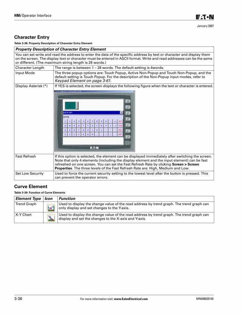
HMi Operator Interface
January 2007
Character Entry
Curve Element
Table 3-38: Property Description of Character Entry Element
Property Description of Character Entry Element
You can set write and read the address to enter the data of the specific address by text or character and display them on the screen. The display text or character must be entered in ASCII format. Write and read addresses can be the same or different. (The maximum string length is 28 words.) Character Length The range is between 1 – 28 words. The default setting is 4words.Input Mode The three popup options are: Touch Popup, Active Non-Popup and Touch Non-Popup, and the
default setting is Touch Popup. For the description of the Non-Popup input modes, refer to Keypad Element on page 3-61.
Display Asterisk (*) If YES is selected, the screen displays the following figure when the text or character is entered.
Fast Refresh If this option is selected, the element can be displayed immediately after switching the screen. Note that only 4 elements (including the display element and the input element) can be fast refreshed on one screen. You can set the Fast Refresh Rate by clicking Screen > Screen Properties. The three levels of the Fast Refresh Rate are: High, Medium and Low.
Set Low Security Used to force the current security setting to the lowest level after the button is pressed. This can prevent the operator errors.
Table 3-39: Function of Curve Elements
Element Type Icon Function
Trend Graph Used to display the change value of the read address by trend graph. The trend graph can only display and set changes to the Y-axis.
X-Y Chart Used to display the change value of the read address by trend graph. The trend graph can display and set the changes to the X-axis and Y-axis.
3-36 For more information visit: www.EatonElectrical.com MN04802014E
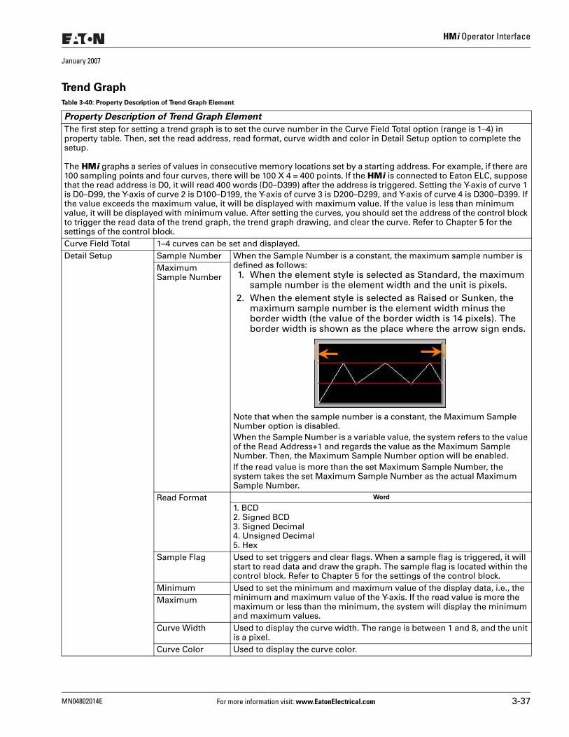
HMi Operator Interface
January 2007
Trend Graph
Table 3-40: Property Description of Trend Graph Element
Property Description of Trend Graph Element
The first step for setting a trend graph is to set the curve number in the Curve Field Total option (range is 1–4) in property table. Then, set the read address, read format, curve width and color in Detail Setup option to complete the setup.
The HMi graphs a series of values in consecutive memory locations set by a starting address. For example, if there are 100 sampling points and four curves, there will be 100 X 4 = 400 points. If the HMi is connected to Eaton ELC, suppose that the read address is D0, it will read 400 words (D0–D399) after the address is triggered. Setting the Y-axis of curve 1 is D0–D99, the Y-axis of curve 2 is D100–D199, the Y-axis of curve 3 is D200–D299, and Y-axis of curve 4 is D300–D399. If the value exceeds the maximum value, it will be displayed with maximum value. If the value is less than minimum value, it will be displayed with minimum value. After setting the curves, you should set the address of the control block to trigger the read data of the trend graph, the trend graph drawing, and clear the curve. Refer to Chapter 5 for the settings of the control block.Curve Field Total 1–4 curves can be set and displayed. Detail Setup Sample Number When the Sample Number is a constant, the maximum sample number is
defined as follows: 1. When the element style is selected as Standard, the maximum
sample number is the element width and the unit is pixels.2. When the element style is selected as Raised or Sunken, the
maximum sample number is the element width minus the border width (the value of the border width is 14 pixels). The border width is shown as the place where the arrow sign ends.
Note that when the sample number is a constant, the Maximum Sample Number option is disabled. When the Sample Number is a variable value, the system refers to the value of the Read Address+1 and regards the value as the Maximum Sample Number. Then, the Maximum Sample Number option will be enabled. If the read value is more than the set Maximum Sample Number, the system takes the set Maximum Sample Number as the actual Maximum Sample Number.
Maximum Sample Number
Read Format Word
1. BCD2. Signed BCD3. Signed Decimal4. Unsigned Decimal5. Hex
Sample Flag Used to set triggers and clear flags. When a sample flag is triggered, it will start to read data and draw the graph. The sample flag is located within the control block. Refer to Chapter 5 for the settings of the control block.
Minimum Used to set the minimum and maximum value of the display data, i.e., the minimum and maximum value of the Y-axis. If the read value is more the maximum or less than the minimum, the system will display the minimum and maximum values.
Maximum
Curve Width Used to display the curve width. The range is between 1 and 8, and the unit is a pixel.
Curve Color Used to display the curve color.
MN04802014E For more information visit: www.EatonElectrical.com 3-37
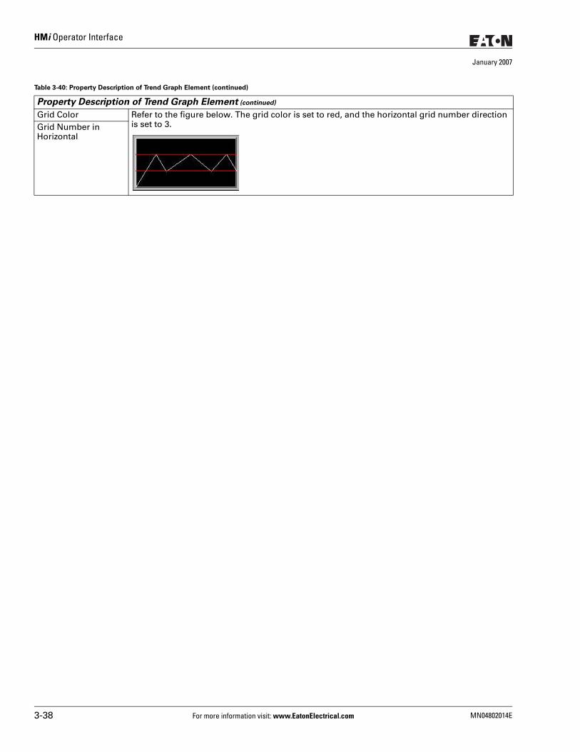
HMi Operator Interface
January 2007
Grid Color Refer to the figure below. The grid color is set to red, and the horizontal grid number direction is set to 3.Grid Number in
Horizontal
Table 3-40: Property Description of Trend Graph Element (continued)
Property Description of Trend Graph Element (continued)
3-38 For more information visit: www.EatonElectrical.com MN04802014E
HMi Operator Interface
January 2007
X-Y ChartTable 3-41: Property Description of X-Y Chart Element
Property Description of X-Y Chart Element
The HMi will convert a series of address values to a X-Y chart on the screen. For example, if there are 100 sample points and four curves, there will be 100 x 4 x 2 = 800 points. If the HMi is connected to Eaton ELC and the read address of the X-axis is D0 and the read address of the Y-axis is D500, it will read 800 words (D0–D399 and D500–D899) after the address is triggered, setting the following curves: ● Setting the X-axis of curve 1 to D0–D99 and the Y-axis of curve 1 to D500–D599 ● Setting the X-axis of curve 2 to D100–D199 and the Y-axis of curve 2 to D600–D699 ● Setting the X-axis of curve 3 to D200–D299 and the Y-axis of curve 3 to D700–D799 ● Setting the X-axis of curve 4 is D300–D399 and the Y-axis of curve 4 to D800–D899
If the value exceeds maximum value, it will be displayed with maximum value. If the value is less than minimum value, it will be displayed with minimum value. After setting the values, you should set the address of the control block to trigger the read data and drawings of the X-Y chart. Refer to Chapter 5 for the settings of the control block.Connect Two Points If the Yes option is selected when drawing the X-Y chart on the screen, the space between two
points on the X-Y chart will be connected by lines.Curve Field Total 1–4 curves can be set and displayed.
MN04802014E For more information visit: www.EatonElectrical.com 3-39
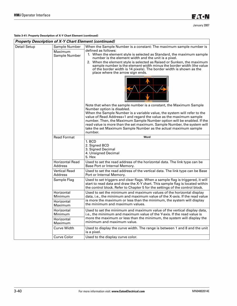
HMi Operator Interface
January 2007
Detail Setup Sample Number When the Sample Number is a constant: The maximum sample number is defined as follows:
1. When the element style is selected as Standard, the maximum sample number is the element width and the unit is a pixel.
2. When the element style is selected as Raised or Sunken, the maximum sample number is the element width minus the border width (the value of the border width is 14 pixels). The border width is shown as the place where the arrow sign ends.
Note that when the sample number is a constant, the Maximum Sample Number option is disabled. When the Sample Number is a variable value, the system will refer to the value of Read Address+1 and regard the value as the maximum sample number. Then, the Maximum Sample Number option will be enabled. If the read value is more than the set maximum. Sample Number, the system will take the set Maximum Sample Number as the actual maximum sample number.
Maximum Sample Number
Read Format Word
1. BCD2. Signed BCD3. Signed Decimal4. Unsigned Decimal5. Hex
Horizontal Read Address
Used to set the read address of the horizontal data. The link type can be Base Port or Internal Memory.
Vertical Read Address
Used to set the read address of the vertical data. The link type can be Base Port or Internal Memory.
Sample Flag Used to set triggers and clear flags. When a sample flag is triggered, it will start to read data and draw the X-Y chart. This sample flag is located within the control block. Refer to Chapter 5 for the settings of the control block.
Horizontal Minimum
Used to set the minimum and maximum values of the horizontal display data, i.e., the minimum and maximum value of the X-axis. If the read value is more the maximum or less than the minimum, the system will display the minimum and maximum values.
Horizontal MaximumHorizontal Minimum
Used to set the minimum and maximum value of the vertical display data, i.e., the minimum and maximum value of the Y-axis. If the read value is more the maximum or less than the minimum, the system will display the minimum and maximum value.
Horizontal MaximumCurve Width Used to display the curve width. The range is between 1 and 8 and the unit
is a pixel. Curve Color Used to the display curve color.
Table 3-41: Property Description of X-Y Chart Element (continued)
Property Description of X-Y Chart Element (continued)
3-40 For more information visit: www.EatonElectrical.com MN04802014E
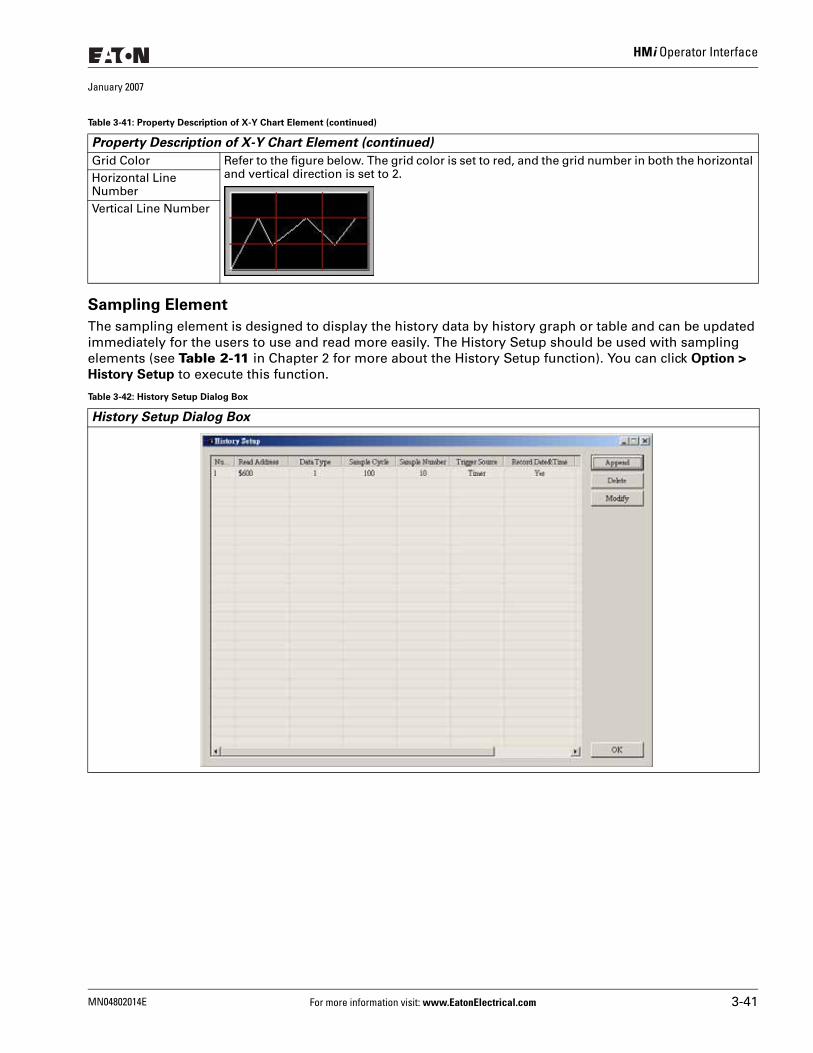
HMi Operator Interface
January 2007
Sampling Element
The sampling element is designed to display the history data by history graph or table and can be updated immediately for the users to use and read more easily. The History Setup should be used with sampling elements (see Table 2-11 in Chapter 2 for more about the History Setup function). You can click Option >
History Setup to execute this function.
Grid Color Refer to the figure below. The grid color is set to red, and the grid number in both the horizontal and vertical direction is set to 2.Horizontal Line
NumberVertical Line Number
Table 3-42: History Setup Dialog Box
History Setup Dialog Box
Table 3-41: Property Description of X-Y Chart Element (continued)
Property Description of X-Y Chart Element (continued)
MN04802014E For more information visit: www.EatonElectrical.com 3-41
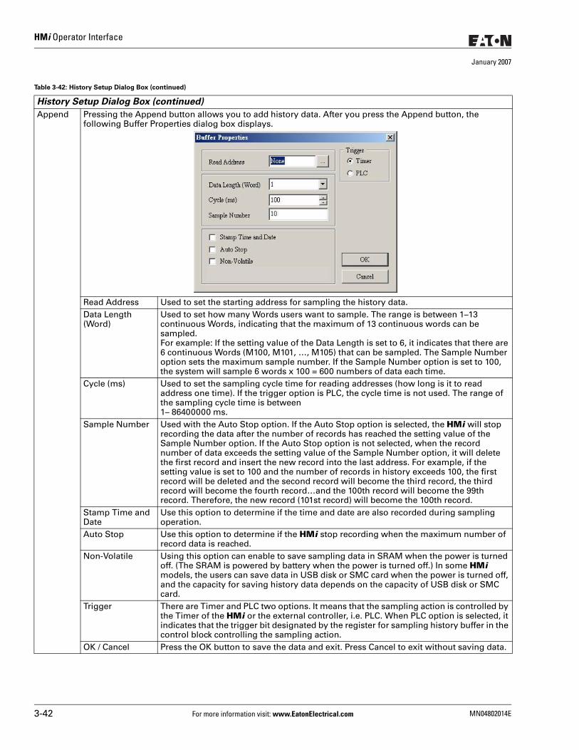
HMi Operator Interface
January 2007
Append Pressing the Append button allows you to add history data. After you press the Append button, the following Buffer Properties dialog box displays.
Read Address Used to set the starting address for sampling the history data.Data Length (Word)
Used to set how many Words users want to sample. The range is between 1–13 continuous Words, indicating that the maximum of 13 continuous words can be sampled.For example: If the setting value of the Data Length is set to 6, it indicates that there are 6 continuous Words (M100, M101, …, M105) that can be sampled. The Sample Number option sets the maximum sample number. If the Sample Number option is set to 100, the system will sample 6 words x 100 = 600 numbers of data each time.
Cycle (ms) Used to set the sampling cycle time for reading addresses (how long is it to read address one time). If the trigger option is PLC, the cycle time is not used. The range of the sampling cycle time is between 1– 86400000 ms.
Sample Number Used with the Auto Stop option. If the Auto Stop option is selected, the HMi will stop recording the data after the number of records has reached the setting value of the Sample Number option. If the Auto Stop option is not selected, when the record number of data exceeds the setting value of the Sample Number option, it will delete the first record and insert the new record into the last address. For example, if the setting value is set to 100 and the number of records in history exceeds 100, the first record will be deleted and the second record will become the third record, the third record will become the fourth record…and the 100th record will become the 99th record. Therefore, the new record (101st record) will become the 100th record.
Stamp Time and Date
Use this option to determine if the time and date are also recorded during sampling operation.
Auto Stop Use this option to determine if the HMi stop recording when the maximum number of record data is reached.
Non-Volatile Using this option can enable to save sampling data in SRAM when the power is turned off. (The SRAM is powered by battery when the power is turned off.) In some HMi models, the users can save data in USB disk or SMC card when the power is turned off, and the capacity for saving history data depends on the capacity of USB disk or SMC card.
Trigger There are Timer and PLC two options. It means that the sampling action is controlled by the Timer of the HMi or the external controller, i.e. PLC. When PLC option is selected, it indicates that the trigger bit designated by the register for sampling history buffer in the control block controlling the sampling action.
OK / Cancel Press the OK button to save the data and exit. Press Cancel to exit without saving data.
Table 3-42: History Setup Dialog Box (continued)
History Setup Dialog Box (continued)
3-42 For more information visit: www.EatonElectrical.com MN04802014E
HMi Operator Interface
January 2007
Delete Pressing the Delete button can delete a history data. Modify Pressing the Modify button can modify a history data.
Table 3-42: History Setup Dialog Box (continued)
History Setup Dialog Box (continued)
MN04802014E For more information visit: www.EatonElectrical.com 3-43
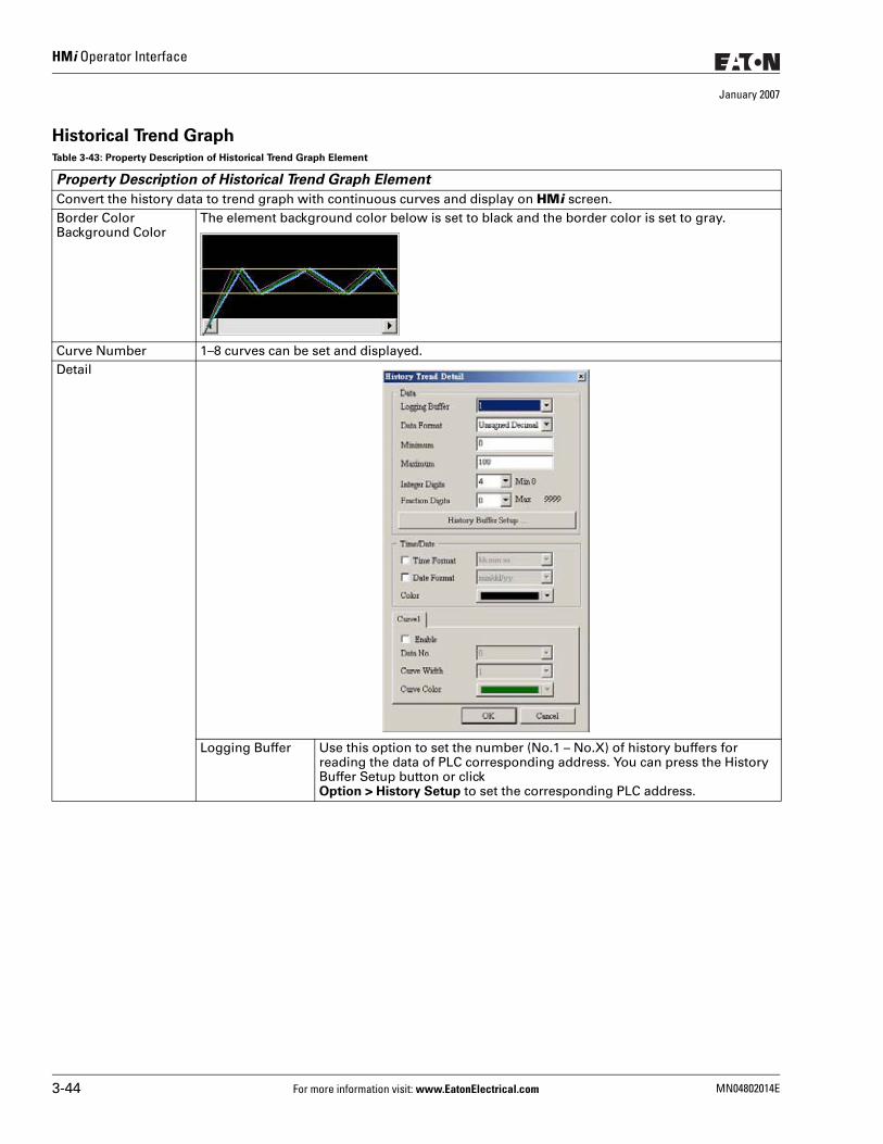
HMi Operator Interface
January 2007
Historical Trend GraphTable 3-43: Property Description of Historical Trend Graph Element
Property Description of Historical Trend Graph Element
Convert the history data to trend graph with continuous curves and display on HMi screen.Border ColorBackground Color
The element background color below is set to black and the border color is set to gray.
Curve Number 1–8 curves can be set and displayed. Detail
Logging Buffer Use this option to set the number (No.1 – No.X) of history buffers for reading the data of PLC corresponding address. You can press the History Buffer Setup button or click Option > History Setup to set the corresponding PLC address.
3-44 For more information visit: www.EatonElectrical.com MN04802014E
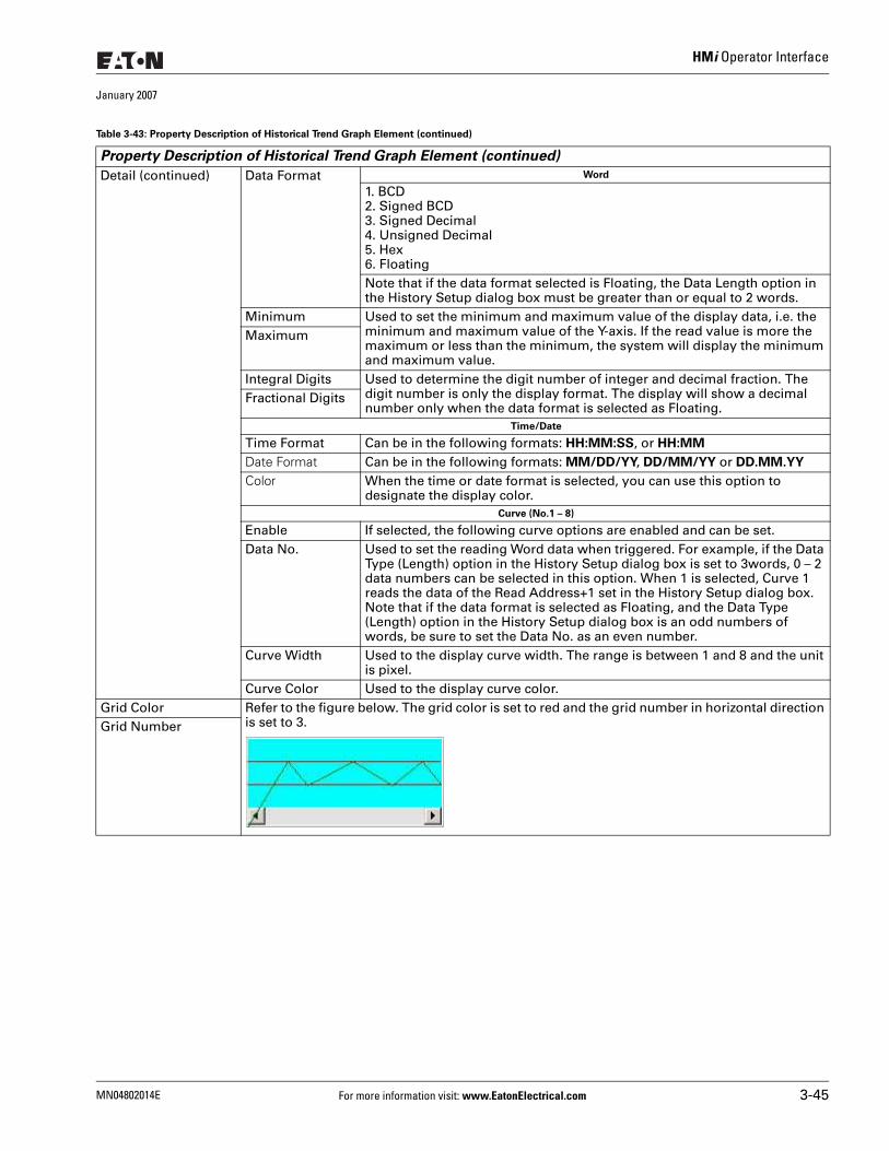
HMi Operator Interface
January 2007
Detail (continued) Data Format Word
1. BCD2. Signed BCD3. Signed Decimal4. Unsigned Decimal5. Hex6. FloatingNote that if the data format selected is Floating, the Data Length option in the History Setup dialog box must be greater than or equal to 2 words.
Minimum Used to set the minimum and maximum value of the display data, i.e. the minimum and maximum value of the Y-axis. If the read value is more the maximum or less than the minimum, the system will display the minimum and maximum value.
Maximum
Integral Digits Used to determine the digit number of integer and decimal fraction. The digit number is only the display format. The display will show a decimal number only when the data format is selected as Floating.
Fractional Digits
Time/Date
Time Format Can be in the following formats: HH:MM:SS, or HH:MM Date Format Can be in the following formats: MM/DD/YY, DD/MM/YY or DD.MM.YY Color When the time or date format is selected, you can use this option to
designate the display color. Curve (No.1 – 8)
Enable If selected, the following curve options are enabled and can be set. Data No. Used to set the reading Word data when triggered. For example, if the Data
Type (Length) option in the History Setup dialog box is set to 3words, 0 – 2 data numbers can be selected in this option. When 1 is selected, Curve 1 reads the data of the Read Address+1 set in the History Setup dialog box.Note that if the data format is selected as Floating, and the Data Type (Length) option in the History Setup dialog box is an odd numbers of words, be sure to set the Data No. as an even number.
Curve Width Used to the display curve width. The range is between 1 and 8 and the unit is pixel.
Curve Color Used to the display curve color. Grid Color Refer to the figure below. The grid color is set to red and the grid number in horizontal direction
is set to 3.Grid Number
Table 3-43: Property Description of Historical Trend Graph Element (continued)
Property Description of Historical Trend Graph Element (continued)
MN04802014E For more information visit: www.EatonElectrical.com 3-45
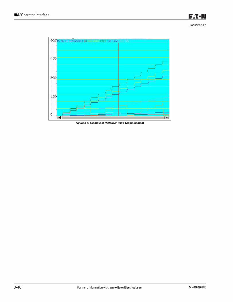
HMi Operator Interface
January 2007
Figure 3-4: Example of Historical Trend Graph Element
3-46 For more information visit: www.EatonElectrical.com MN04802014E
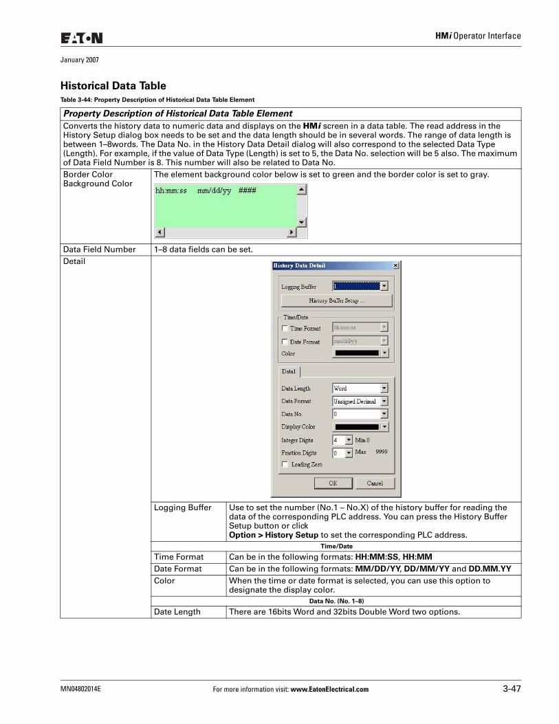
HMi Operator Interface
January 2007
Historical Data TableTable 3-44: Property Description of Historical Data Table Element
Property Description of Historical Data Table Element
Converts the history data to numeric data and displays on the HMi screen in a data table. The read address in the History Setup dialog box needs to be set and the data length should be in several words. The range of data length is between 1–8words. The Data No. in the History Data Detail dialog will also correspond to the selected Data Type (Length). For example, if the value of Data Type (Length) is set to 5, the Data No. selection will be 5 also. The maximum of Data Field Number is 8. This number will also be related to Data No. Border ColorBackground Color
The element background color below is set to green and the border color is set to gray.
Data Field Number 1–8 data fields can be set.Detail
Logging Buffer Use to set the number (No.1 – No.X) of the history buffer for reading the data of the corresponding PLC address. You can press the History Buffer Setup button or click Option > History Setup to set the corresponding PLC address.
Time/Date
Time Format Can be in the following formats: HH:MM:SS, HH:MM
Date Format Can be in the following formats: MM/DD/YY, DD/MM/YY and DD.MM.YY Color When the time or date format is selected, you can use this option to
designate the display color. Data No. (No. 1–8)
Date Length There are 16bits Word and 32bits Double Word two options.
MN04802014E For more information visit: www.EatonElectrical.com 3-47
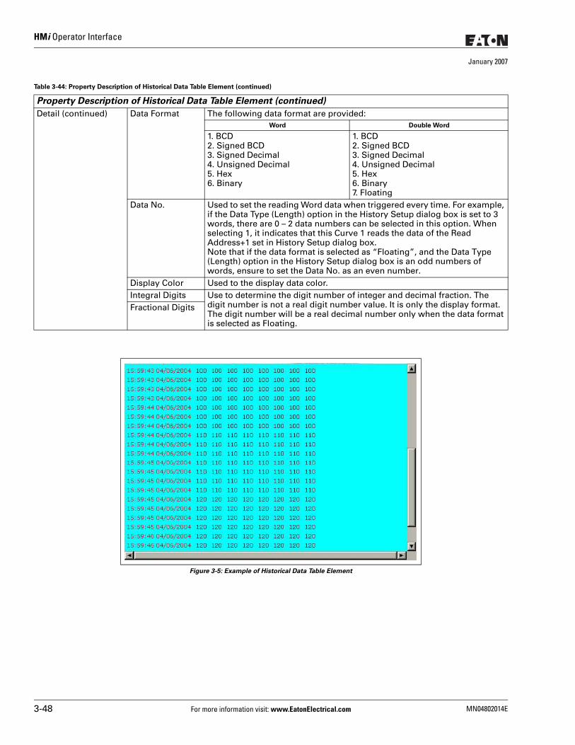
HMi Operator Interface
January 2007
Figure 3-5: Example of Historical Data Table Element
Detail (continued) Data Format The following data format are provided:Word Double Word
1. BCD2. Signed BCD3. Signed Decimal4. Unsigned Decimal5. Hex6. Binary
1. BCD2. Signed BCD3. Signed Decimal4. Unsigned Decimal5. Hex6. Binary7. Floating
Data No. Used to set the reading Word data when triggered every time. For example, if the Data Type (Length) option in the History Setup dialog box is set to 3 words, there are 0 – 2 data numbers can be selected in this option. When selecting 1, it indicates that this Curve 1 reads the data of the Read Address+1 set in History Setup dialog box.Note that if the data format is selected as “Floating”, and the Data Type (Length) option in the History Setup dialog box is an odd numbers of words, ensure to set the Data No. as an even number.
Display Color Used to the display data color. Integral Digits Use to determine the digit number of integer and decimal fraction. The
digit number is not a real digit number value. It is only the display format. The digit number will be a real decimal number only when the data format is selected as Floating.
Fractional Digits
Table 3-44: Property Description of Historical Data Table Element (continued)
Property Description of Historical Data Table Element (continued)
3-48 For more information visit: www.EatonElectrical.com MN04802014E
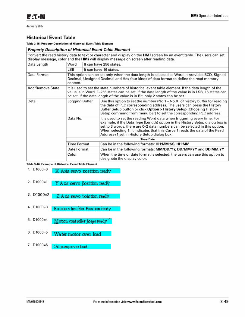
HMi Operator Interface
January 2007
Historical Event Table
Table 3-46: Example of Historical Event Table Element
Table 3-45: Property Description of Historical Event Table Element
Property Description of Historical Event Table Element
Convert the read history data to text or character and display on the HMi screen by an event table. The users can set display message, color and the HMi will display message on screen after reading data. Data Length Word It can have 256 states.
LSB It can have 16 states. Data Format This option can be set only when the data length is selected as Word. It provides BCD, Signed
Decimal, Unsigned Decimal and Hex four kinds of data format to define the read memory content.
Add/Remove State It is used to set the state numbers of historical event table element. If the data length of the value is in Word, 1–256 states can be set. If the data length of the value is in LSB, 16 states can be set. If the data length of the value is in Bit, only 2 states can be set.
Detail Logging Buffer Use this option to set the number (No.1 – No.X) of history buffer for reading the data of PLC corresponding address. The users can press the History Buffer Setup button or click Option > History Setup (Choosing History Setup command from menu bar) to set the corresponding PLC address.
Data No. It is used to set the reading Word data when triggering every time. For example, if the Data Type (Length) option in the History Setup dialog box is set to 3 words, there are 0–2 data numbers can be selected in this option. When selecting 1, it indicates that this Curve 1 reads the data of the Read Address+1 set in History Setup dialog box.
Time/Date
Time Format Can be in the following formats: HH:MM:SS, HH:MM
Date Format Can be in the following formats: MM/DD/YY, DD/MM/YY and DD.MM.YY Color When the time or date format is selected, the users can use this option to
designate the display color.
1. D1000=0
2. D1000=1
3. D1000=2
4. D1000=3
5. D1000=4
6. D1000=5
7. D1000=6
MN04802014E For more information visit: www.EatonElectrical.com 3-49
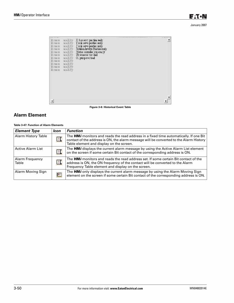
HMi Operator Interface
January 2007
Figure 3-6: Historical Event Table
Alarm Element
Table 3-47: Function of Alarm Elements
Element Type Icon Function
Alarm History Table The HMi monitors and reads the read address in a fixed time automatically. If one Bit contact of the address is ON, the alarm message will be converted to the Alarm History Table element and display on the screen.
Active Alarm List The HMi displays the current alarm message by using the Active Alarm List element on the screen if some certain Bit contact of the corresponding address is ON.
Alarm Frequency Table
The HMi monitors and reads the read address set. If some certain Bit contact of the address is ON, the ON frequency of the contact will be converted to the Alarm Frequency Table element and display on the screen.
Alarm Moving Sign The HMi only displays the current alarm message by using the Alarm Moving Sign element on the screen if some certain Bit contact of the corresponding address is ON.
3-50 For more information visit: www.EatonElectrical.com MN04802014E
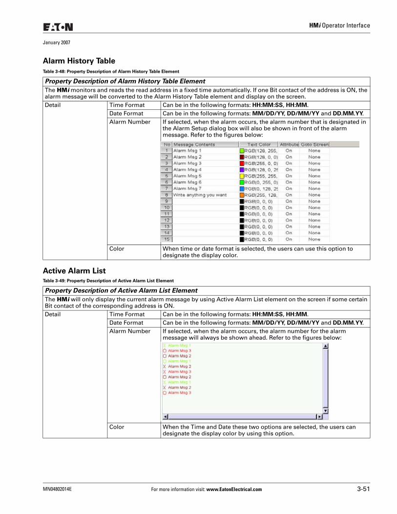
HMi Operator Interface
January 2007
Alarm History Table
Active Alarm List
Table 3-48: Property Description of Alarm History Table Element
Property Description of Alarm History Table Element
The HMi monitors and reads the read address in a fixed time automatically. If one Bit contact of the address is ON, the alarm message will be converted to the Alarm History Table element and display on the screen. Detail Time Format Can be in the following formats: HH:MM:SS, HH:MM.
Date Format Can be in the following formats: MM/DD/YY, DD/MM/YY and DD.MM.YY.Alarm Number If selected, when the alarm occurs, the alarm number that is designated in
the Alarm Setup dialog box will also be shown in front of the alarm message. Refer to the figures below:
Color When time or date format is selected, the users can use this option to designate the display color.
Table 3-49: Property Description of Active Alarm List Element
Property Description of Active Alarm List Element
The HMi will only display the current alarm message by using Active Alarm List element on the screen if some certain Bit contact of the corresponding address is ON. Detail Time Format Can be in the following formats: HH:MM:SS, HH:MM.
Date Format Can be in the following formats: MM/DD/YY, DD/MM/YY and DD.MM.YY.Alarm Number If selected, when the alarm occurs, the alarm number for the alarm
message will always be shown ahead. Refer to the figures below:
Color When the Time and Date these two options are selected, the users can designate the display color by using this option.
MN04802014E For more information visit: www.EatonElectrical.com 3-51
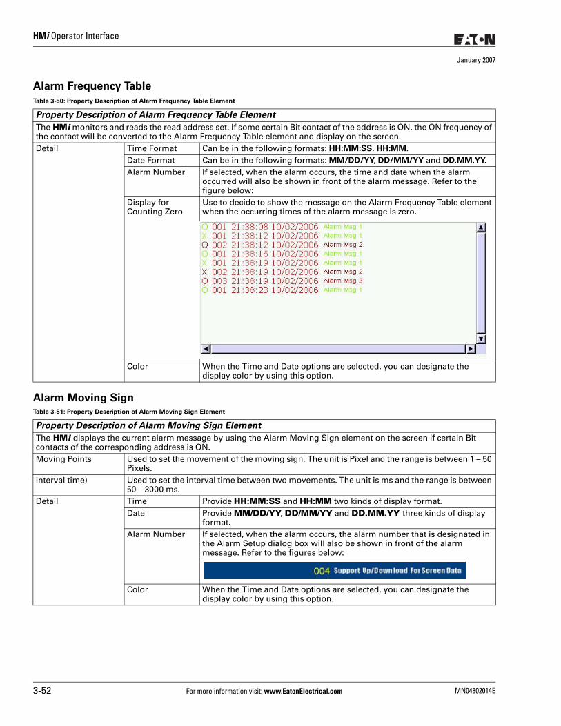
HMi Operator Interface
January 2007
Alarm Frequency Table
Alarm Moving Sign
Table 3-50: Property Description of Alarm Frequency Table Element
Property Description of Alarm Frequency Table Element
The HMi monitors and reads the read address set. If some certain Bit contact of the address is ON, the ON frequency of the contact will be converted to the Alarm Frequency Table element and display on the screen. Detail Time Format Can be in the following formats: HH:MM:SS, HH:MM.
Date Format Can be in the following formats: MM/DD/YY, DD/MM/YY and DD.MM.YY.Alarm Number If selected, when the alarm occurs, the time and date when the alarm
occurred will also be shown in front of the alarm message. Refer to the figure below:
Display for Counting Zero
Use to decide to show the message on the Alarm Frequency Table element when the occurring times of the alarm message is zero.
Color When the Time and Date options are selected, you can designate the display color by using this option.
Table 3-51: Property Description of Alarm Moving Sign Element
Property Description of Alarm Moving Sign Element
The HMi displays the current alarm message by using the Alarm Moving Sign element on the screen if certain Bit contacts of the corresponding address is ON. Moving Points Used to set the movement of the moving sign. The unit is Pixel and the range is between 1 – 50
Pixels.Interval time) Used to set the interval time between two movements. The unit is ms and the range is between
50 – 3000 ms.Detail Time Provide HH:MM:SS and HH:MM two kinds of display format.
Date Provide MM/DD/YY, DD/MM/YY and DD.MM.YY three kinds of display format.
Alarm Number If selected, when the alarm occurs, the alarm number that is designated in the Alarm Setup dialog box will also be shown in front of the alarm message. Refer to the figures below:
Color When the Time and Date options are selected, you can designate the display color by using this option.
3-52 For more information visit: www.EatonElectrical.com MN04802014E
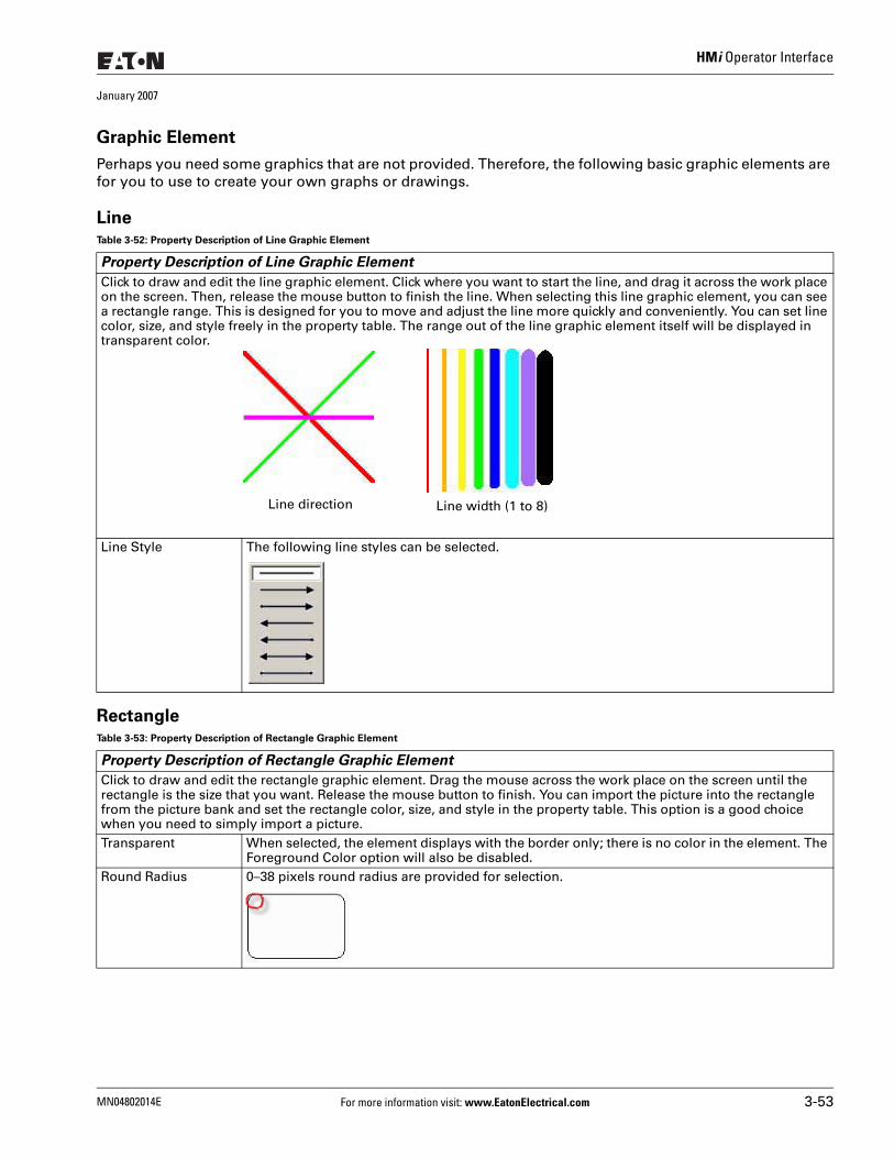
HMi Operator Interface
January 2007
Graphic Element
Perhaps you need some graphics that are not provided. Therefore, the following basic graphic elements are for you to use to create your own graphs or drawings.
Line
Rectangle
Table 3-52: Property Description of Line Graphic Element
Property Description of Line Graphic Element
Click to draw and edit the line graphic element. Click where you want to start the line, and drag it across the work place on the screen. Then, release the mouse button to finish the line. When selecting this line graphic element, you can see a rectangle range. This is designed for you to move and adjust the line more quickly and conveniently. You can set line color, size, and style freely in the property table. The range out of the line graphic element itself will be displayed in transparent color.
Line Style The following line styles can be selected.
Table 3-53: Property Description of Rectangle Graphic Element
Property Description of Rectangle Graphic Element
Click to draw and edit the rectangle graphic element. Drag the mouse across the work place on the screen until the rectangle is the size that you want. Release the mouse button to finish. You can import the picture into the rectangle from the picture bank and set the rectangle color, size, and style in the property table. This option is a good choice when you need to simply import a picture.Transparent When selected, the element displays with the border only; there is no color in the element. The
Foreground Color option will also be disabled.Round Radius 0–38 pixels round radius are provided for selection.
Line direction Line width (1 to 8)
MN04802014E For more information visit: www.EatonElectrical.com 3-53
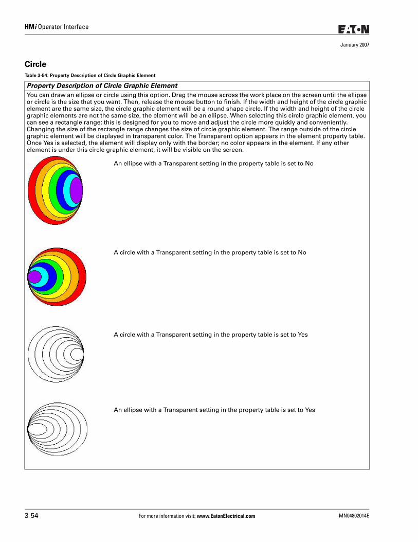
HMi Operator Interface
January 2007
Circle
Table 3-54: Property Description of Circle Graphic Element
Property Description of Circle Graphic Element
You can draw an ellipse or circle using this option. Drag the mouse across the work place on the screen until the ellipse or circle is the size that you want. Then, release the mouse button to finish. If the width and height of the circle graphic element are the same size, the circle graphic element will be a round shape circle. If the width and height of the circle graphic elements are not the same size, the element will be an ellipse. When selecting this circle graphic element, you can see a rectangle range; this is designed for you to move and adjust the circle more quickly and conveniently. Changing the size of the rectangle range changes the size of circle graphic element. The range outside of the circle graphic element will be displayed in transparent color. The Transparent option appears in the element property table. Once Yes is selected, the element will display only with the border; no color appears in the element. If any other element is under this circle graphic element, it will be visible on the screen.
An ellipse with a Transparent setting in the property table is set to No
A circle with a Transparent setting in the property table is set to No
A circle with a Transparent setting in the property table is set to Yes
An ellipse with a Transparent setting in the property table is set to Yes
3-54 For more information visit: www.EatonElectrical.com MN04802014E
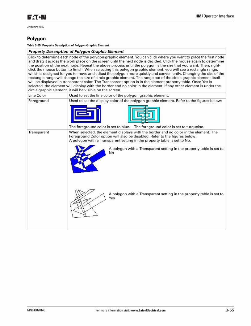
HMi Operator Interface
January 2007
Polygon
Table 3-55: Property Description of Polygon Graphic Element
Property Description of Polygon Graphic Element
Click to determine each node of the polygon graphic element. You can click where you want to place the first node and drag it across the work place on the screen until the next node is decided. Click the mouse again to determine the position of the next node. Repeat the above process until the polygon is the size that you want. Then, right-click the mouse button to finish. When selecting this polygon graphic element, you will see a rectangle range, which is designed for you to move and adjust the polygon more quickly and conveniently. Changing the size of the rectangle range will change the size of circle graphic element. The range out of the circle graphic element itself will be displayed in transparent color. The Transparent option is in the element property table. Once Yes is selected, the element will display with the border and no color in the element. If any other element is under the circle graphic element, it will be visible on the screen.Line Color Used to set the line color of the polygon graphic element.Foreground Used to set the display color of the polygon graphic element. Refer to the figures below:
The foreground color is set to blue. The foreground color is set to turquoise.Transparent When selected, the element displays with the border and no color in the element. The
Foreground Color option will also be disabled. Refer to the figures below:A polygon with a Transparent setting in the property table is set to No.
A polygon with a Transparent setting in the property table is set to No
A polygon with a Transparent setting in the property table is set to Yes
MN04802014E For more information visit: www.EatonElectrical.com 3-55
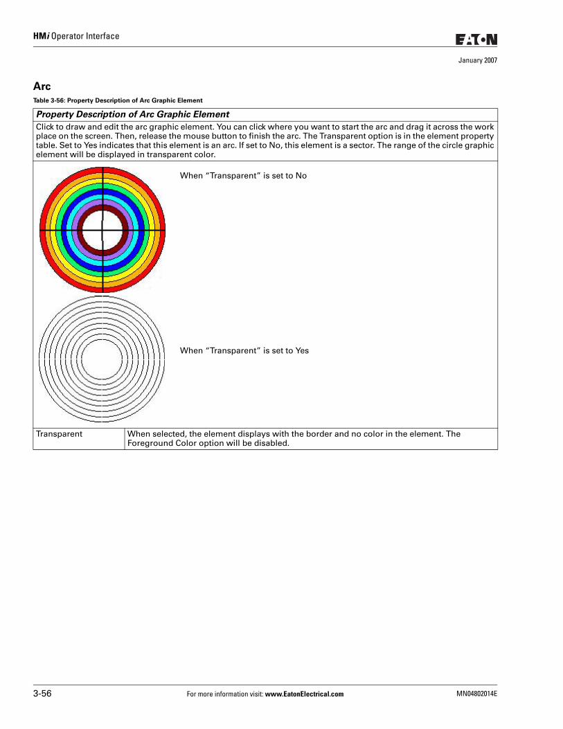
HMi Operator Interface
January 2007
ArcTable 3-56: Property Description of Arc Graphic Element
Property Description of Arc Graphic Element
Click to draw and edit the arc graphic element. You can click where you want to start the arc and drag it across the work place on the screen. Then, release the mouse button to finish the arc. The Transparent option is in the element property table. Set to Yes indicates that this element is an arc. If set to No, this element is a sector. The range of the circle graphic element will be displayed in transparent color.
When “Transparent” is set to No
When “Transparent” is set to Yes
Transparent When selected, the element displays with the border and no color in the element. The Foreground Color option will be disabled.
3-56 For more information visit: www.EatonElectrical.com MN04802014E
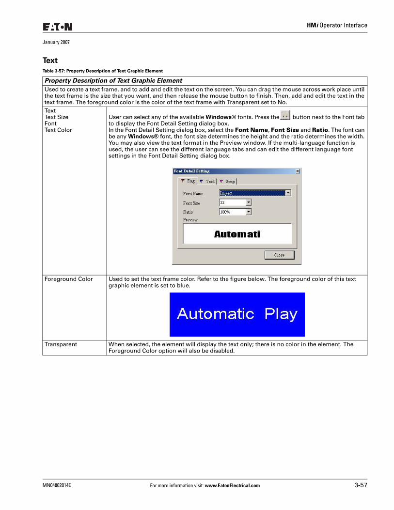
HMi Operator Interface
January 2007
Text
Table 3-57: Property Description of Text Graphic Element
Property Description of Text Graphic Element
Used to create a text frame, and to add and edit the text on the screen. You can drag the mouse across work place until the text frame is the size that you want, and then release the mouse button to finish. Then, add and edit the text in the text frame. The foreground color is the color of the text frame with Transparent set to No.TextText SizeFontText Color
User can select any of the available Windows® fonts. Press the button next to the Font tab to display the Font Detail Setting dialog box.In the Font Detail Setting dialog box, select the Font Name, Font Size and Ratio. The font can be any Windows® font, the font size determines the height and the ratio determines the width. You may also view the text format in the Preview window. If the multi-language function is used, the user can see the different language tabs and can edit the different language font settings in the Font Detail Setting dialog box.
Foreground Color Used to set the text frame color. Refer to the figure below. The foreground color of this text graphic element is set to blue.
Transparent When selected, the element will display the text only; there is no color in the element. The Foreground Color option will also be disabled.
MN04802014E For more information visit: www.EatonElectrical.com 3-57
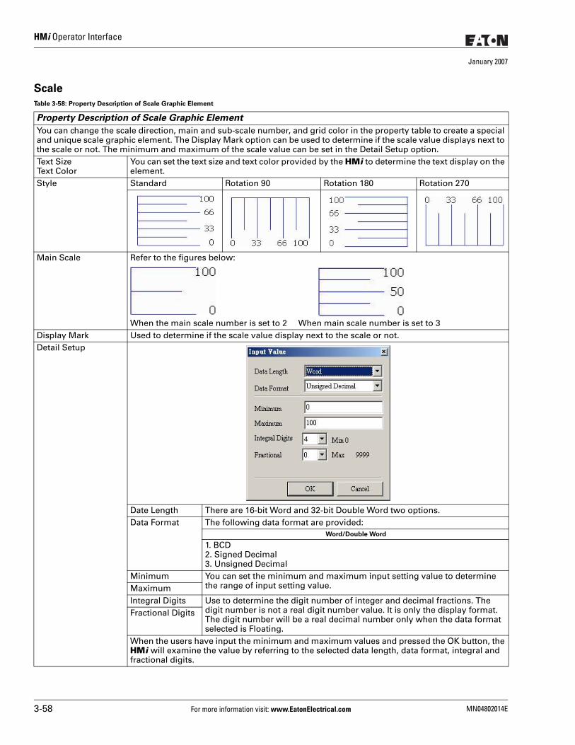
HMi Operator Interface
January 2007
Scale
Table 3-58: Property Description of Scale Graphic Element
Property Description of Scale Graphic Element
You can change the scale direction, main and sub-scale number, and grid color in the property table to create a special and unique scale graphic element. The Display Mark option can be used to determine if the scale value displays next to the scale or not. The minimum and maximum of the scale value can be set in the Detail Setup option.Text SizeText Color
You can set the text size and text color provided by the HMi to determine the text display on the element.
Style Standard Rotation 90 Rotation 180 Rotation 270
Main Scale Refer to the figures below:
When the main scale number is set to 2 When main scale number is set to 3Display Mark Used to determine if the scale value display next to the scale or not.Detail Setup
Date Length There are 16-bit Word and 32-bit Double Word two options.Data Format The following data format are provided:
Word/Double Word
1. BCD2. Signed Decimal3. Unsigned Decimal
Minimum You can set the minimum and maximum input setting value to determine the range of input setting value. Maximum
Integral Digits Use to determine the digit number of integer and decimal fractions. The digit number is not a real digit number value. It is only the display format. The digit number will be a real decimal number only when the data format selected is Floating.
Fractional Digits
When the users have input the minimum and maximum values and pressed the OK button, the HMi will examine the value by referring to the selected data length, data format, integral and fractional digits.
3-58 For more information visit: www.EatonElectrical.com MN04802014E
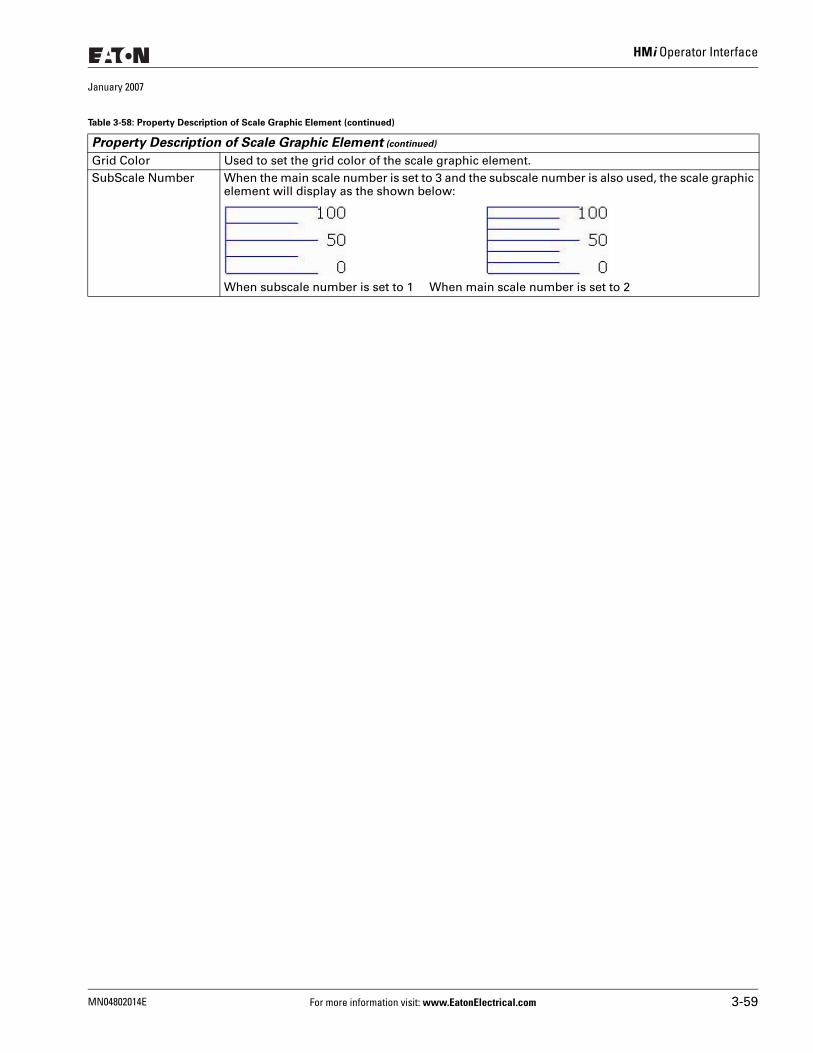
HMi Operator Interface
January 2007
Grid Color Used to set the grid color of the scale graphic element.SubScale Number When the main scale number is set to 3 and the subscale number is also used, the scale graphic
element will display as the shown below:
When subscale number is set to 1 When main scale number is set to 2
Table 3-58: Property Description of Scale Graphic Element (continued)
Property Description of Scale Graphic Element (continued)
MN04802014E For more information visit: www.EatonElectrical.com 3-59
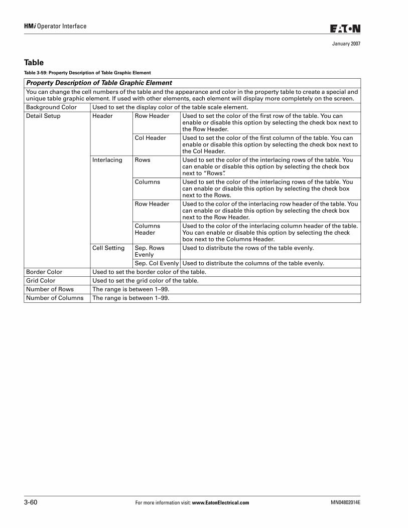
HMi Operator Interface
January 2007
TableTable 3-59: Property Description of Table Graphic Element
Property Description of Table Graphic Element
You can change the cell numbers of the table and the appearance and color in the property table to create a special and unique table graphic element. If used with other elements, each element will display more completely on the screen. Background Color Used to set the display color of the table scale element. Detail Setup Header Row Header Used to set the color of the first row of the table. You can
enable or disable this option by selecting the check box next to the Row Header.
Col Header Used to set the color of the first column of the table. You can enable or disable this option by selecting the check box next to the Col Header.
Interlacing Rows Used to set the color of the interlacing rows of the table. You can enable or disable this option by selecting the check box next to “Rows”.
Columns Used to set the color of the interlacing rows of the table. You can enable or disable this option by selecting the check box next to the Rows.
Row Header Used to the color of the interlacing row header of the table. You can enable or disable this option by selecting the check box next to the Row Header.
Columns Header
Used to the color of the interlacing column header of the table. You can enable or disable this option by selecting the check box next to the Columns Header.
Cell Setting Sep. Rows Evenly
Used to distribute the rows of the table evenly.
Sep. Col Evenly Used to distribute the columns of the table evenly.Border Color Used to set the border color of the table. Grid Color Used to set the grid color of the table. Number of Rows The range is between 1–99.Number of Columns The range is between 1–99.
3-60 For more information visit: www.EatonElectrical.com MN04802014E
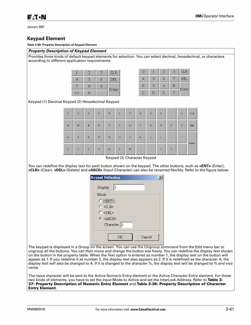
HMi Operator Interface
January 2007
Keypad ElementTable 3-60: Property Description of Keypad Element
Property Description of Keypad Element
Provides three kinds of default keypad elements for selection. You can select decimal, hexadecimal, or characters according to different application requirements.
Keypad (1) Decimal Keypad (2) Hexadecimal Keypad
Keypad (3) Character Keypad
You can redefine the display text for each button shown on the keypad. The other buttons, such as <ENT> (Enter), <CLR> (Clear), <DEL> (Delete) and <ASCII> (Input Character) can also be renamed flexibly. Refer to the figure below:
The keypad is displayed in a Group on the screen. You can use the Ungroup command from the Edit menu bar to ungroup all the buttons. You can then move and change the button size freely. You can redefine the display text shown on the button in the property table. When the Text option is entered as number 1, the display text on the button will appear as 1. If you redefine it as number 2, the display text also appears as 2. If it is redefined as the character A, the display text will also be changed to A. If it is changed to the character %, the display text will be changed to % and vice versa.
The input character will be sent to the Active Numeric Entry element or the Active Character Entry element. For these two kinds of elements, you have to set the Input Mode to Active and set the InterLock Address. Refer to Table 3-37: Property Description of Numeric Entry Element and Table 3-38: Property Description of Character Entry Element.
MN04802014E For more information visit: www.EatonElectrical.com 3-61
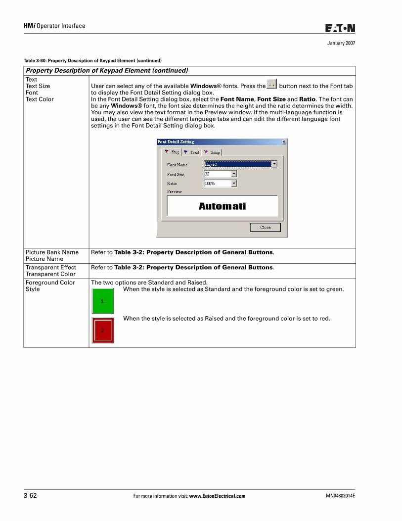
HMi Operator Interface
January 2007
TextText SizeFontText Color
User can select any of the available Windows® fonts. Press the button next to the Font tab to display the Font Detail Setting dialog box.In the Font Detail Setting dialog box, select the Font Name, Font Size and Ratio. The font can be any Windows® font, the font size determines the height and the ratio determines the width. You may also view the text format in the Preview window. If the multi-language function is used, the user can see the different language tabs and can edit the different language font settings in the Font Detail Setting dialog box.
Picture Bank NamePicture Name
Refer to Table 3-2: Property Description of General Buttons.
Transparent EffectTransparent Color
Refer to Table 3-2: Property Description of General Buttons.
Foreground ColorStyle
The two options are Standard and Raised. When the style is selected as Standard and the foreground color is set to green.
When the style is selected as Raised and the foreground color is set to red.
Table 3-60: Property Description of Keypad Element (continued)
Property Description of Keypad Element (continued)
3-62 For more information visit: www.EatonElectrical.com MN04802014E
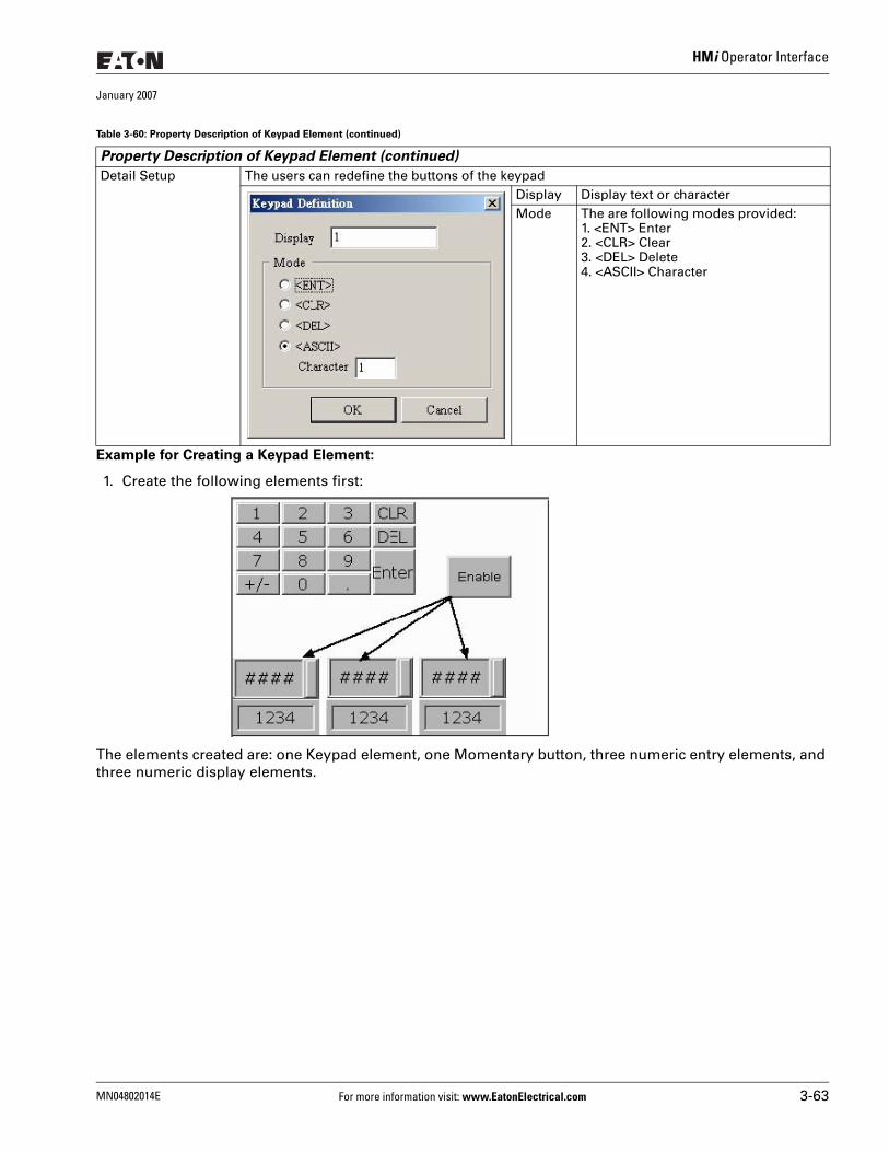
HMi Operator Interface
January 2007
Example for Creating a Keypad Element:
1. Create the following elements first:
The elements created are: one Keypad element, one Momentary button, three numeric entry elements, and three numeric display elements.
Detail Setup The users can redefine the buttons of the keypadDisplay Display text or characterMode The are following modes provided:
1. <ENT> Enter2. <CLR> Clear3. <DEL> Delete4. <ASCII> Character
Table 3-60: Property Description of Keypad Element (continued)
Property Description of Keypad Element (continued)
MN04802014E For more information visit: www.EatonElectrical.com 3-63
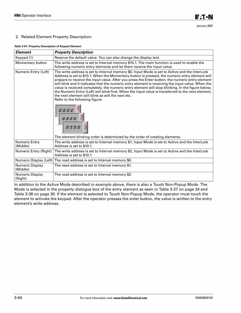
HMi Operator Interface
January 2007
2. Related Element Property Description:
In addition to the Active Mode described in example above, there is also a Touch Non-Popup Mode. The Mode is selected in the property dialogue box of the entry element as seen in Table 3-37 on page 34 and Table 3-38 on page 36. If the element is selected to Touch Non-Popup Mode, the operator must touch the element to activate the keypad. After the operator presses the enter button, the value is written to the entry element’s write address.
Table 3-61: Property Description of Keypad Element
Element Property Description
Keypad (1) Reserve the default value. You can also change the display text. Momentary button The write address is set to Internal memory $10.1. The main function is used to enable the
following numeric entry elements and let them receive the input value. Numeric Entry (Left) The write address is set to Internal memory $0, Input Mode is set to Active and the InterLock
Address is set to $10.1. When the Momentary button is pressed, the numeric entry element will prepare to receive the input value. After you press the Enter button, the numeric entry element will blink and it indicates that the numeric entry element is receiving the input value. When the value is received completely, the numeric entry element will stop blinking. In the figure below, the Numeric Entry (Left) will blink first. When the input value is transferred to the next element, the next element will blink as will the next etc. Refer to the following figure:
The element blinking order is determined by the order of creating elements.Numeric Entry (Middle)
The write address is set to Internal memory $1, Input Mode is set to Active and the InterLock Address is set to $10.1.
Numeric Entry (Right) The write address is set to Internal memory $2, Input Mode is set to Active and the InterLock Address is set to $10.1.
Numeric Display (Left) The read address is set to Internal memory $0. Numeric Display (Middle)
The read address is set to Internal memory $1.
Numeric Display (Right)
The read address is set to Internal memory $2.
3-64 For more information visit: www.EatonElectrical.com MN04802014E
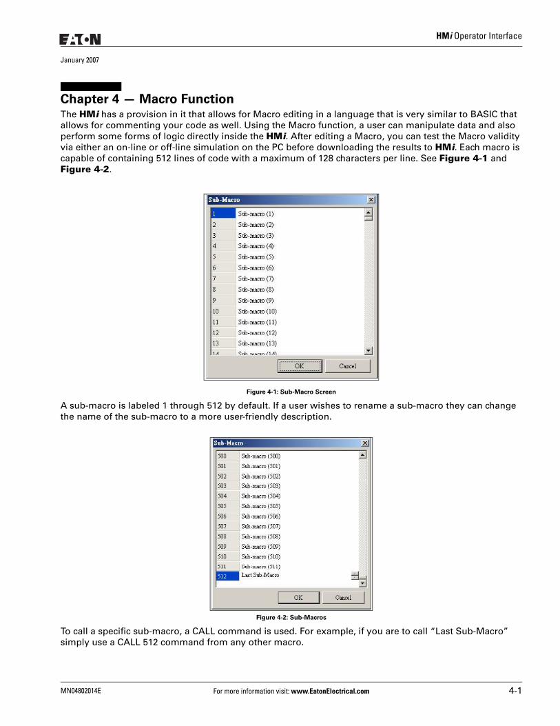
HMi Operator Interface
January 2007
Chapter 4 — Macro FunctionThe HMi has a provision in it that allows for Macro editing in a language that is very similar to BASIC that allows for commenting your code as well. Using the Macro function, a user can manipulate data and also perform some forms of logic directly inside the HMi. After editing a Macro, you can test the Macro validity via either an on-line or off-line simulation on the PC before downloading the results to HMi. Each macro is capable of containing 512 lines of code with a maximum of 128 characters per line. See Figure 4-1 and Figure 4-2.
Figure 4-1: Sub-Macro Screen
A sub-macro is labeled 1 through 512 by default. If a user wishes to rename a sub-macro they can change the name of the sub-macro to a more user-friendly description.
Figure 4-2: Sub-Macros
To call a specific sub-macro, a CALL command is used. For example, if you are to call “Last Sub-Macro” simply use a CALL 512 command from any other macro.
MN04802014E For more information visit: www.EatonElectrical.com 4-1
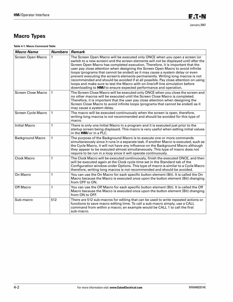
HMi Operator Interface
January 2007
Macro Types
Table 4-1: Macro Command Table
Macro Name Numbers Remark
Screen Open Macro 1 The Screen Open Macro will be executed only ONCE when you open a screen (or switch to a new screen) and the screen elements will not be displayed until after the Screen Open Macro has completed execution. Therefore, it is important that the user pay close attention when designing the Screen Open Macro to avoid infinite loops (programs that cannot be ended) as it may cause a system delay or even prevent executing the screen’s elements permanently. Writing long macros is not recommended and should be avoided if at all possible. Pay close attention on using loops and make sure to test the Macro with on-line/off-line simulation before downloading to HMi to ensure expected performance and operation.
Screen Close Macro 1 The Screen Close Macro will be executed only ONCE when you close the screen and no other macros will be executed until the Screen Close Macro is completed. Therefore, it is important that the user pay close attention when designing the Screen Close Macro to avoid infinite loops (programs that cannot be ended) as it may cause a system delay.
Screen Cycle Macro 1 The macro will be executed continuously when the screen is open, therefore, writing long macros is not recommended and should be avoided for this type of macro.
Initial Macro 1 There is only one Initial Macro in a program and it is executed just prior to the startup screen being displayed. This macro is very useful when setting initial values in the HMi or in a PLC.
Background Macro 1 The purpose of the Background Macro is to execute one or more commands simultaneously since it runs in a separate task. If another Macro is executed, such as the Cycle Macro, it will not have any influence on the Background Macro although they appear to be executed almost simultaneously. This type of macro does not require to be run in a loop since it will operate continuously.
Clock Macro 1 The Clock Macro will be executed continuously, finish the executed ONCE, and then will be executed again at the Clock cycle time set in the Standard tab of the Configuration window under Options. This type of macro is similar to a Cycle Macro therefore, writing long macros is not recommended and should be avoided.
On Macro 1 You can use the On Macro for each specific button element (Bit). It is called the On Macro because the Macro is executed once upon the button element (Bit) changing from OFF to ON.
Off Macro 1 You can use the Off Macro for each specific button element (Bit). It is called the Off Macro because the Macro is executed once upon the button element (Bit) changing from ON to OFF.
Sub-macro 512 There are 512 sub-macros for editing that can be used to write repeated actions or functions to save macro editing time. To call a sub-macro simply, use a CALL command from within a macro; an example would be CALL 1 to call the first sub-macro.
4-2 For more information visit: www.EatonElectrical.com MN04802014E
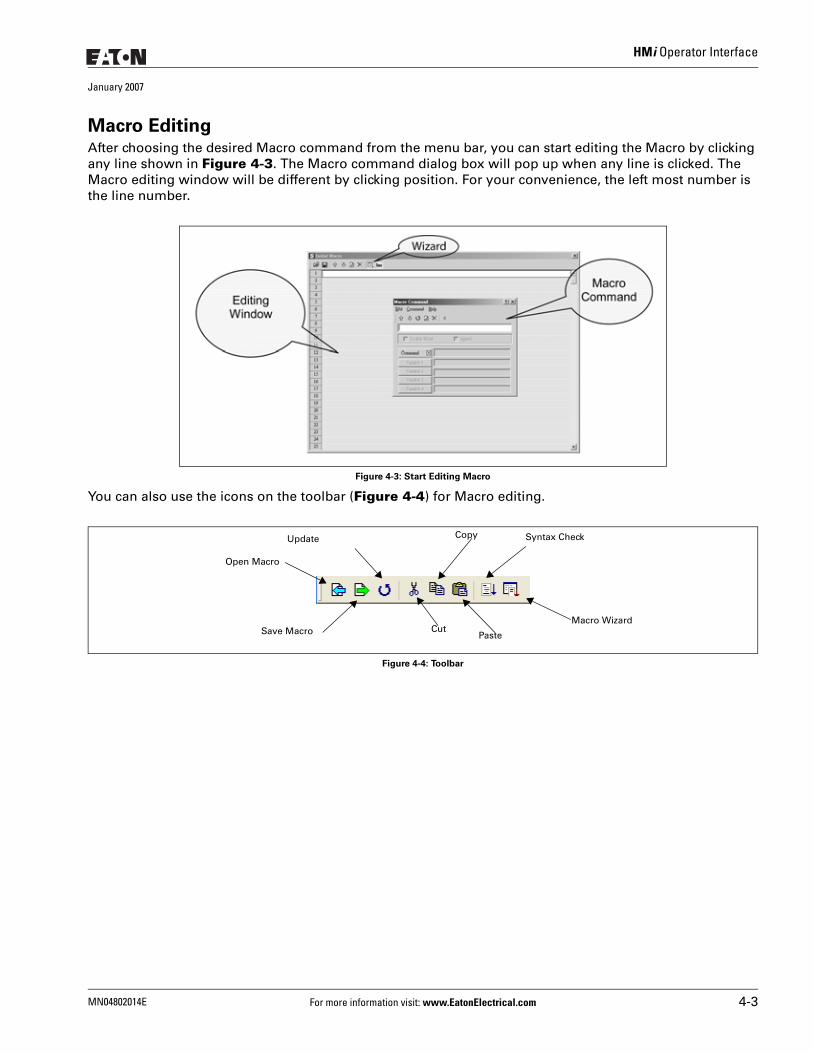
HMi Operator Interface
January 2007
Macro EditingAfter choosing the desired Macro command from the menu bar, you can start editing the Macro by clicking any line shown in Figure 4-3. The Macro command dialog box will pop up when any line is clicked. The Macro editing window will be different by clicking position. For your convenience, the left most number is the line number.
Figure 4-3: Start Editing Macro
You can also use the icons on the toolbar (Figure 4-4) for Macro editing.
Figure 4-4: Toolbar
Open Macro
Save Macro
Update Copy
PasteCut
Macro Wizard
Syntax Check
MN04802014E For more information visit: www.EatonElectrical.com 4-3
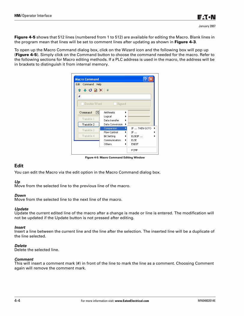
HMi Operator Interface
January 2007
Figure 4-5 shows that 512 lines (numbered from 1 to 512) are available for editing the Macro. Blank lines in the program mean that lines will be set to comment lines after updating as shown in Figure 4-3.
To open up the Macro Command dialog box, click on the Wizard icon and the following box will pop up (Figure 4-5). Simply click on the Command button to choose the command needed for the macro. Refer to the following sections for Macro editing methods. If a PLC address is used in the macro, the address will be in brackets to distinguish it from internal memory.
Figure 4-5: Macro Command Editing Window
Edit
You can edit the Macro via the edit option in the Macro Command dialog box.
UpMove from the selected line to the previous line of the macro.
DownMove from the selected line to the next line of the macro.
UpdateUpdate the current edited line of the macro after a change is made or line is entered. The modification will not be updated if the Update button is not pressed after editing.
InsertInsert a line between the current line and the line after the selection. The inserted line will be a duplicate of the line selected.
DeleteDelete the selected line.
CommentThis will insert a comment mark (#) in front of the line to mark the line as a comment. Choosing Comment again will remove the comment mark.
4-4 For more information visit: www.EatonElectrical.com MN04802014E
HMi Operator Interface
January 2007
Command
You can use commands to edit the macro. The command and equation can be typed directly, or chosen from the menu bar or selected by clicking the Command button.
Keypad Entry
For the convenience of editing the macro, the HMi allows you to edit the Macro by keying in the commands manually. The HMi will check the validity automatically, if there are any errors, a warning dialog box will pop up to warn you. It is not critical that the user place the correct amount of spaces between commands and operands, when the line is updated the HMi will automatically adjust the spacing and warn of formatting errors.
MN04802014E For more information visit: www.EatonElectrical.com 4-5
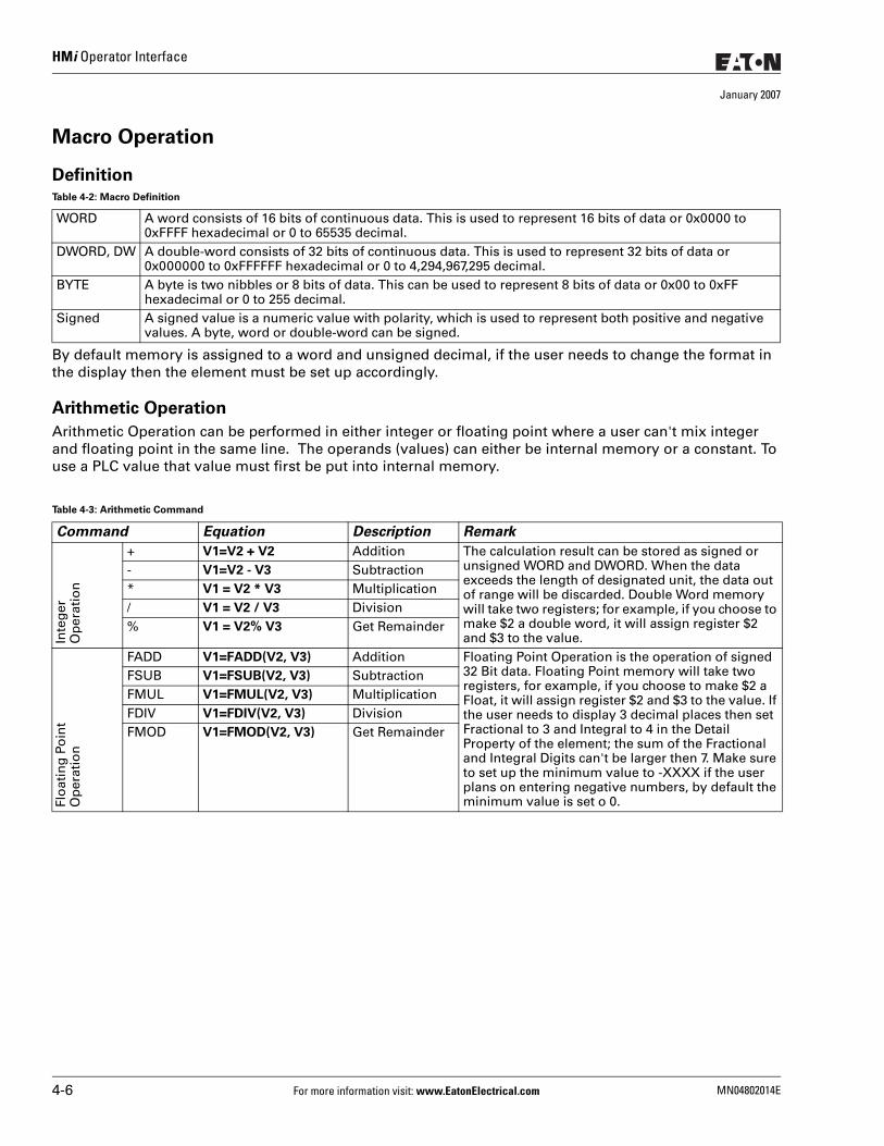
HMi Operator Interface
January 2007
Macro Operation
Definition
By default memory is assigned to a word and unsigned decimal, if the user needs to change the format in the display then the element must be set up accordingly.
Arithmetic Operation
Arithmetic Operation can be performed in either integer or floating point where a user can't mix integer and floating point in the same line. The operands (values) can either be internal memory or a constant. To use a PLC value that value must first be put into internal memory.
Table 4-2: Macro Definition
WORD A word consists of 16 bits of continuous data. This is used to represent 16 bits of data or 0x0000 to 0xFFFF hexadecimal or 0 to 65535 decimal.
DWORD, DW A double-word consists of 32 bits of continuous data. This is used to represent 32 bits of data or 0x000000 to 0xFFFFFF hexadecimal or 0 to 4,294,967,295 decimal.
BYTE A byte is two nibbles or 8 bits of data. This can be used to represent 8 bits of data or 0x00 to 0xFF hexadecimal or 0 to 255 decimal.
Signed A signed value is a numeric value with polarity, which is used to represent both positive and negative values. A byte, word or double-word can be signed.
Table 4-3: Arithmetic Command
Command Equation Description Remark
Inte
ger
O
per
atio
n
+ V1=V2 + V2 Addition The calculation result can be stored as signed or unsigned WORD and DWORD. When the data exceeds the length of designated unit, the data out of range will be discarded. Double Word memory will take two registers; for example, if you choose to make $2 a double word, it will assign register $2 and $3 to the value.
- V1=V2 - V3 Subtraction* V1 = V2 * V3 Multiplication/ V1 = V2 / V3 Division% V1 = V2% V3 Get Remainder
Flo
atin
g P
oin
t O
per
atio
n
FADD V1=FADD(V2, V3) Addition Floating Point Operation is the operation of signed 32 Bit data. Floating Point memory will take two registers, for example, if you choose to make $2 a Float, it will assign register $2 and $3 to the value. If the user needs to display 3 decimal places then set Fractional to 3 and Integral to 4 in the Detail Property of the element; the sum of the Fractional and Integral Digits can't be larger then 7. Make sure to set up the minimum value to -XXXX if the user plans on entering negative numbers, by default the minimum value is set o 0.
FSUB V1=FSUB(V2, V3) SubtractionFMUL V1=FMUL(V2, V3) MultiplicationFDIV V1=FDIV(V2, V3) DivisionFMOD V1=FMOD(V2, V3) Get Remainder
4-6 For more information visit: www.EatonElectrical.com MN04802014E
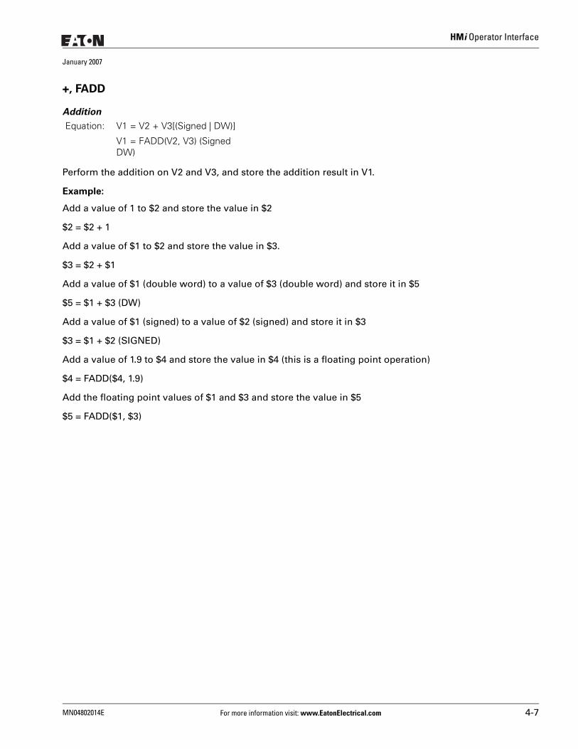
HMi Operator Interface
January 2007
+, FADD
Addition
Perform the addition on V2 and V3, and store the addition result in V1.
Example:
Add a value of 1 to $2 and store the value in $2
$2 = $2 + 1
Add a value of $1 to $2 and store the value in $3.
$3 = $2 + $1
Add a value of $1 (double word) to a value of $3 (double word) and store it in $5
$5 = $1 + $3 (DW)
Add a value of $1 (signed) to a value of $2 (signed) and store it in $3
$3 = $1 + $2 (SIGNED)
Add a value of 1.9 to $4 and store the value in $4 (this is a floating point operation)
$4 = FADD($4, 1.9)
Add the floating point values of $1 and $3 and store the value in $5
$5 = FADD($1, $3)
Equation: V1 = V2 + V3[(Signed | DW)]
V1 = FADD(V2, V3) (Signed DW)
MN04802014E For more information visit: www.EatonElectrical.com 4-7
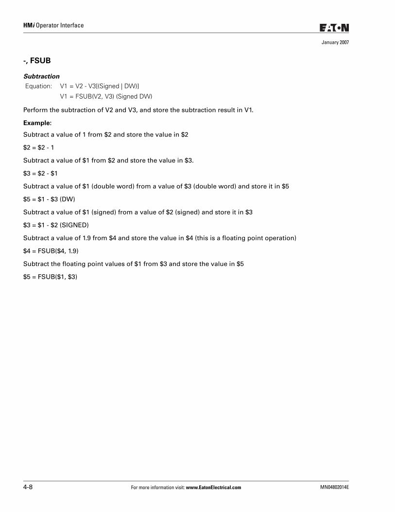
HMi Operator Interface
January 2007
-, FSUB
Subtraction
Perform the subtraction of V2 and V3, and store the subtraction result in V1.
Example:
Subtract a value of 1 from $2 and store the value in $2
$2 = $2 - 1
Subtract a value of $1 from $2 and store the value in $3.
$3 = $2 - $1
Subtract a value of $1 (double word) from a value of $3 (double word) and store it in $5
$5 = $1 - $3 (DW)
Subtract a value of $1 (signed) from a value of $2 (signed) and store it in $3
$3 = $1 - $2 (SIGNED)
Subtract a value of 1.9 from $4 and store the value in $4 (this is a floating point operation)
$4 = FSUB($4, 1.9)
Subtract the floating point values of $1 from $3 and store the value in $5
$5 = FSUB($1, $3)
Equation: V1 = V2 - V3[(Signed | DW)]
V1 = FSUB(V2, V3) (Signed DW)
4-8 For more information visit: www.EatonElectrical.com MN04802014E
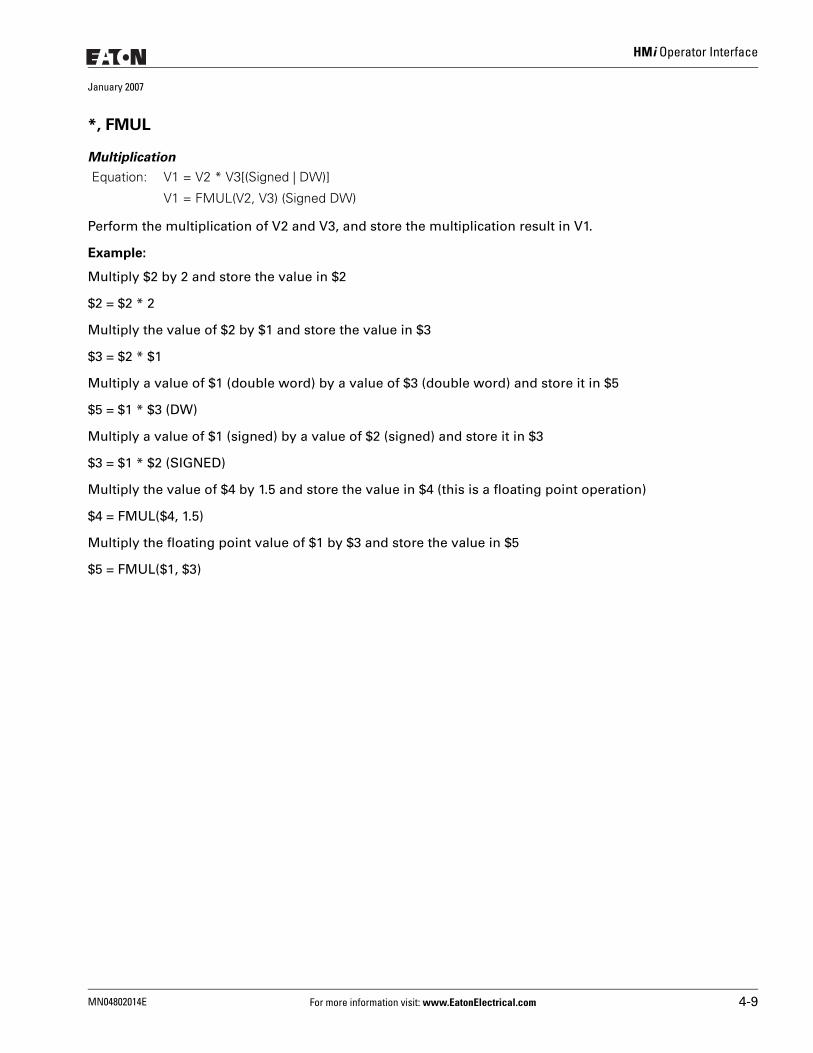
HMi Operator Interface
January 2007
*, FMUL
Multiplication
Perform the multiplication of V2 and V3, and store the multiplication result in V1.
Example:
Multiply $2 by 2 and store the value in $2
$2 = $2 * 2
Multiply the value of $2 by $1 and store the value in $3
$3 = $2 * $1
Multiply a value of $1 (double word) by a value of $3 (double word) and store it in $5
$5 = $1 * $3 (DW)
Multiply a value of $1 (signed) by a value of $2 (signed) and store it in $3
$3 = $1 * $2 (SIGNED)
Multiply the value of $4 by 1.5 and store the value in $4 (this is a floating point operation)
$4 = FMUL($4, 1.5)
Multiply the floating point value of $1 by $3 and store the value in $5
$5 = FMUL($1, $3)
Equation: V1 = V2 * V3[(Signed | DW)]
V1 = FMUL(V2, V3) (Signed DW)
MN04802014E For more information visit: www.EatonElectrical.com 4-9
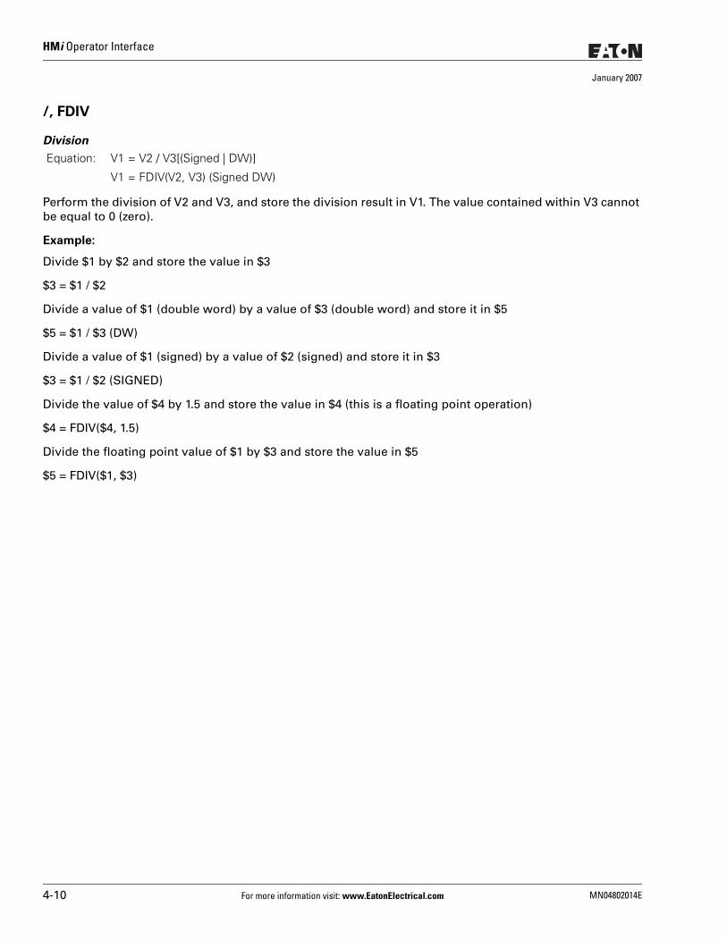
HMi Operator Interface
January 2007
/, FDIV
Division
Perform the division of V2 and V3, and store the division result in V1. The value contained within V3 cannot be equal to 0 (zero).
Example:
Divide $1 by $2 and store the value in $3
$3 = $1 / $2
Divide a value of $1 (double word) by a value of $3 (double word) and store it in $5
$5 = $1 / $3 (DW)
Divide a value of $1 (signed) by a value of $2 (signed) and store it in $3
$3 = $1 / $2 (SIGNED)
Divide the value of $4 by 1.5 and store the value in $4 (this is a floating point operation)
$4 = FDIV($4, 1.5)
Divide the floating point value of $1 by $3 and store the value in $5
$5 = FDIV($1, $3)
Equation: V1 = V2 / V3[(Signed | DW)]
V1 = FDIV(V2, V3) (Signed DW)
4-10 For more information visit: www.EatonElectrical.com MN04802014E
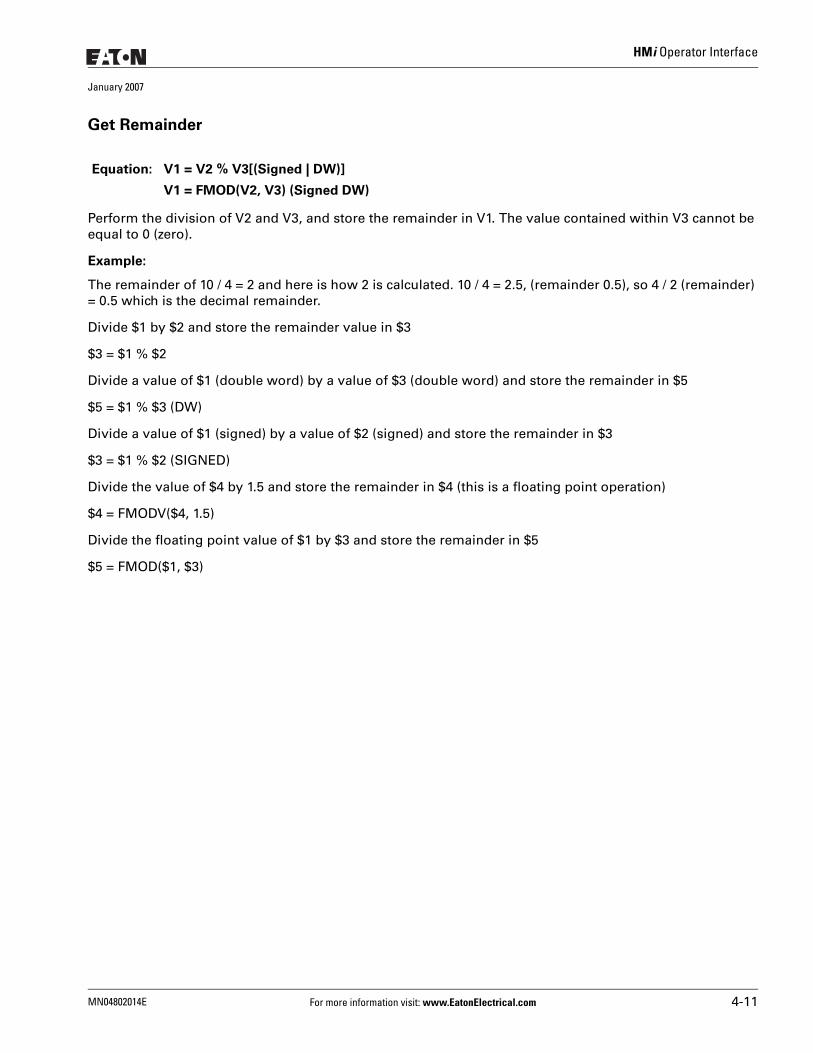
HMi Operator Interface
January 2007
Get Remainder
Perform the division of V2 and V3, and store the remainder in V1. The value contained within V3 cannot be equal to 0 (zero).
Example:
The remainder of 10 / 4 = 2 and here is how 2 is calculated. 10 / 4 = 2.5, (remainder 0.5), so 4 / 2 (remainder) = 0.5 which is the decimal remainder.
Divide $1 by $2 and store the remainder value in $3
$3 = $1 % $2
Divide a value of $1 (double word) by a value of $3 (double word) and store the remainder in $5
$5 = $1 % $3 (DW)
Divide a value of $1 (signed) by a value of $2 (signed) and store the remainder in $3
$3 = $1 % $2 (SIGNED)
Divide the value of $4 by 1.5 and store the remainder in $4 (this is a floating point operation)
$4 = FMODV($4, 1.5)
Divide the floating point value of $1 by $3 and store the remainder in $5
$5 = FMOD($1, $3)
Equation: V1 = V2 % V3[(Signed | DW)]
V1 = FMOD(V2, V3) (Signed DW)
MN04802014E For more information visit: www.EatonElectrical.com 4-11
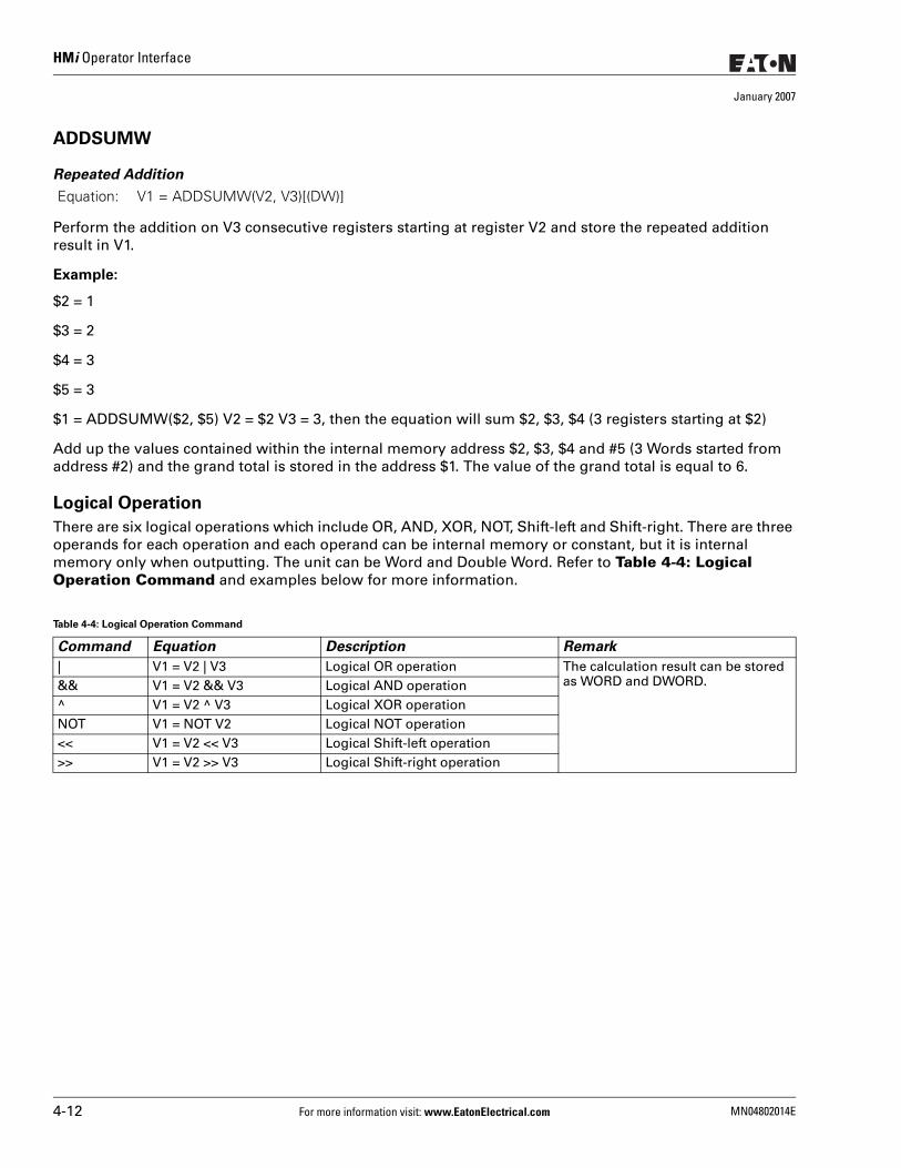
HMi Operator Interface
January 2007
ADDSUMW
Repeated Addition
Perform the addition on V3 consecutive registers starting at register V2 and store the repeated addition result in V1.
Example:
$2 = 1
$3 = 2
$4 = 3
$5 = 3
$1 = ADDSUMW($2, $5) V2 = $2 V3 = 3, then the equation will sum $2, $3, $4 (3 registers starting at $2)
Add up the values contained within the internal memory address $2, $3, $4 and #5 (3 Words started from address #2) and the grand total is stored in the address $1. The value of the grand total is equal to 6.
Logical Operation
There are six logical operations which include OR, AND, XOR, NOT, Shift-left and Shift-right. There are three operands for each operation and each operand can be internal memory or constant, but it is internal memory only when outputting. The unit can be Word and Double Word. Refer to Table 4-4: Logical Operation Command and examples below for more information.
Equation: V1 = ADDSUMW(V2, V3)[(DW)]
Table 4-4: Logical Operation Command
Command Equation Description Remark
| V1 = V2 | V3 Logical OR operation The calculation result can be stored as WORD and DWORD.&& V1 = V2 && V3 Logical AND operation
^ V1 = V2 ^ V3 Logical XOR operation NOT V1 = NOT V2 Logical NOT operation<< V1 = V2 << V3 Logical Shift-left operation>> V1 = V2 >> V3 Logical Shift-right operation
4-12 For more information visit: www.EatonElectrical.com MN04802014E
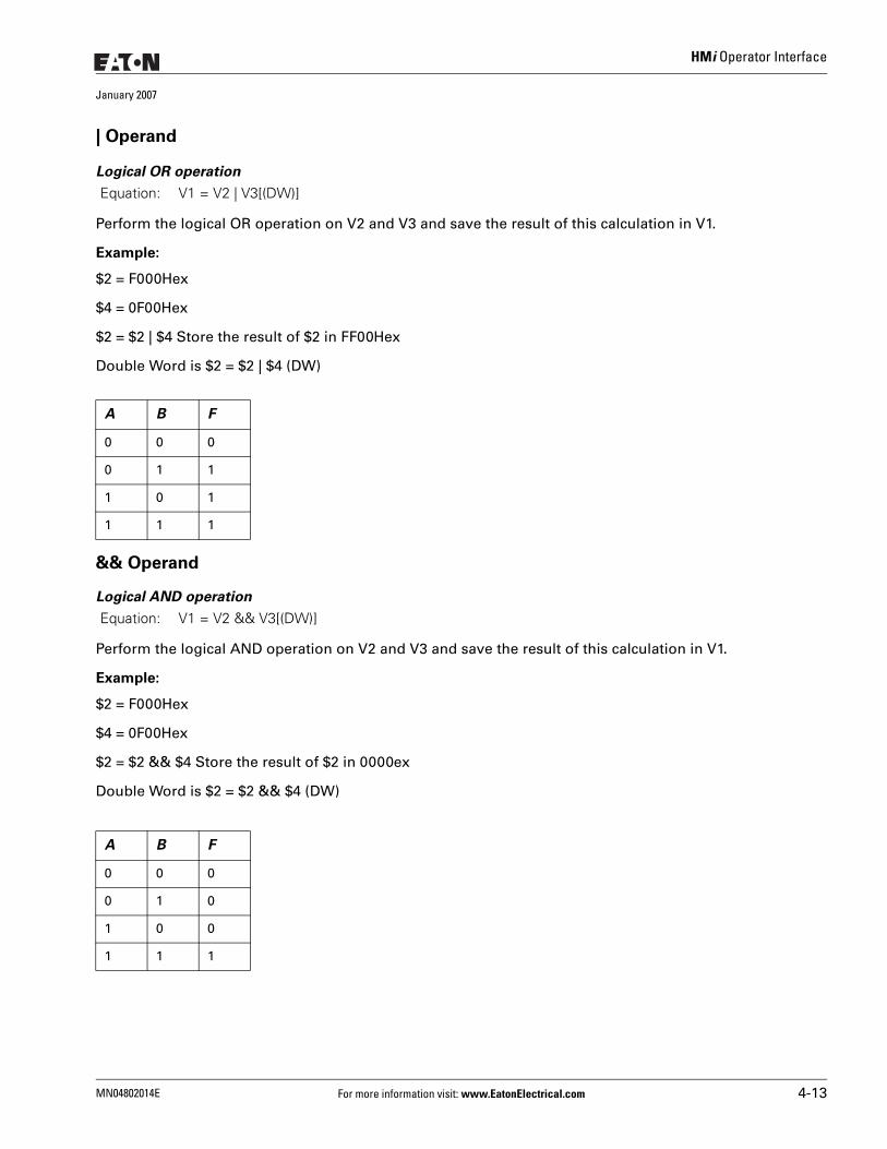
HMi Operator Interface
January 2007
| Operand
Logical OR operation
Perform the logical OR operation on V2 and V3 and save the result of this calculation in V1.
Example:
$2 = F000Hex
$4 = 0F00Hex
$2 = $2 | $4 Store the result of $2 in FF00Hex
Double Word is $2 = $2 | $4 (DW)
&& Operand
Logical AND operation
Perform the logical AND operation on V2 and V3 and save the result of this calculation in V1.
Example:
$2 = F000Hex
$4 = 0F00Hex
$2 = $2 && $4 Store the result of $2 in 0000ex
Double Word is $2 = $2 && $4 (DW)
Equation: V1 = V2 | V3[(DW)]
A B F
0 0 0
0 1 1
1 0 1
1 1 1
Equation: V1 = V2 && V3[(DW)]
A B F
0 0 0
0 1 0
1 0 0
1 1 1
MN04802014E For more information visit: www.EatonElectrical.com 4-13
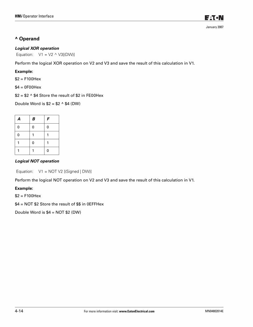
HMi Operator Interface
January 2007
^ Operand
Logical XOR operation
Perform the logical XOR operation on V2 and V3 and save the result of this calculation in V1.
Example:
$2 = F100Hex
$4 = 0F00Hex
$2 = $2 ^ $4 Store the result of $2 in FE00Hex
Double Word is $2 = $2 ^ $4 (DW)
Logical NOT operation
Perform the logical NOT operation on V2 and V3 and save the result of this calculation in V1.
Example:
$2 = F100Hex
$4 = NOT $2 Store the result of $$ in 0EFFHex
Double Word is $4 = NOT $2 (DW)
Equation: V1 = V2 ^ V3[(DW)]
A B F
0 0 0
0 1 1
1 0 1
1 1 0
Equation: V1 = NOT V2 [(Signed | DW)]
4-14 For more information visit: www.EatonElectrical.com MN04802014E
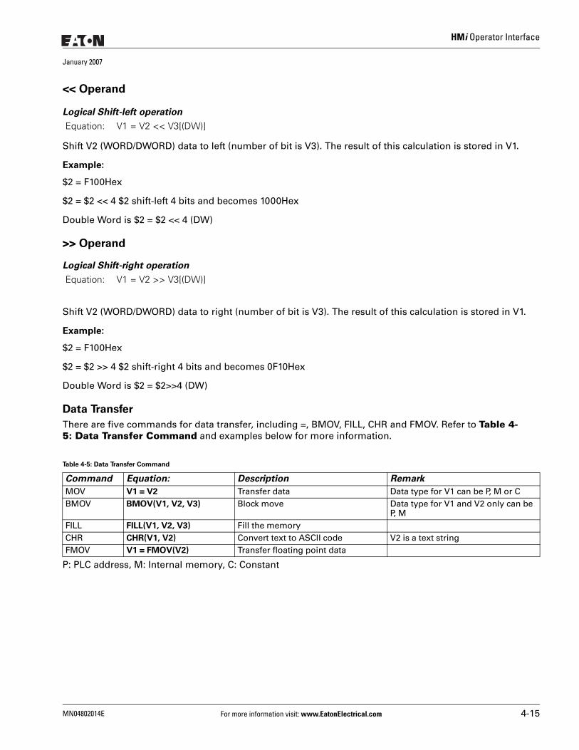
HMi Operator Interface
January 2007
<< Operand
Logical Shift-left operation
Shift V2 (WORD/DWORD) data to left (number of bit is V3). The result of this calculation is stored in V1.
Example:
$2 = F100Hex
$2 = $2 << 4 $2 shift-left 4 bits and becomes 1000Hex
Double Word is $2 = $2 << 4 (DW)
>> Operand
Logical Shift-right operation
Shift V2 (WORD/DWORD) data to right (number of bit is V3). The result of this calculation is stored in V1.
Example:
$2 = F100Hex
$2 = $2 >> 4 $2 shift-right 4 bits and becomes 0F10Hex
Double Word is $2 = $2>>4 (DW)
Data Transfer
There are five commands for data transfer, including =, BMOV, FILL, CHR and FMOV. Refer to Table 4-5: Data Transfer Command and examples below for more information.
P: PLC address, M: Internal memory, C: Constant
Equation: V1 = V2 << V3[(DW)]
Equation: V1 = V2 >> V3[(DW)]
Table 4-5: Data Transfer Command
Command Equation: Description Remark
MOV V1 = V2 Transfer data Data type for V1 can be P, M or CBMOV BMOV(V1, V2, V3) Block move Data type for V1 and V2 only can be
P, MFILL FILL(V1, V2, V3) Fill the memoryCHR CHR(V1, V2) Convert text to ASCII code V2 is a text stringFMOV V1 = FMOV(V2) Transfer floating point data
MN04802014E For more information visit: www.EatonElectrical.com 4-15
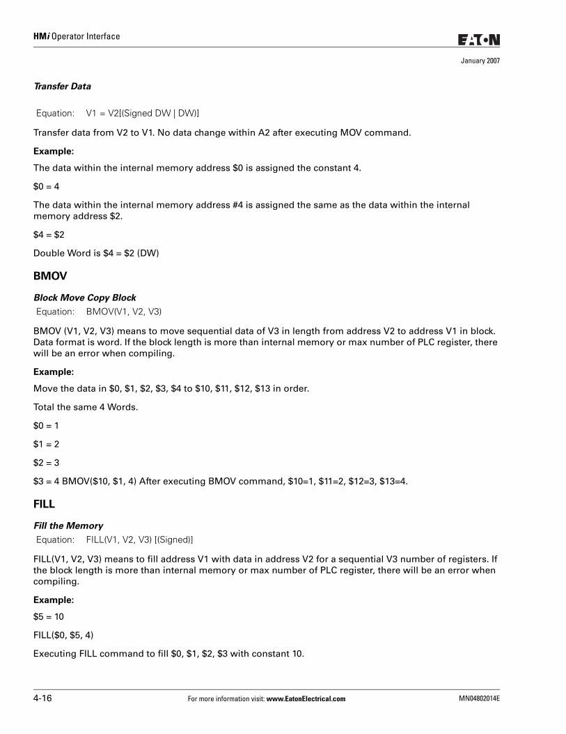
HMi Operator Interface
January 2007
Transfer Data
Transfer data from V2 to V1. No data change within A2 after executing MOV command.
Example:
The data within the internal memory address $0 is assigned the constant 4.
$0 = 4
The data within the internal memory address #4 is assigned the same as the data within the internal memory address $2.
$4 = $2
Double Word is $4 = $2 (DW)
BMOV
Block Move Copy Block
BMOV (V1, V2, V3) means to move sequential data of V3 in length from address V2 to address V1 in block. Data format is word. If the block length is more than internal memory or max number of PLC register, there will be an error when compiling.
Example:
Move the data in $0, $1, $2, $3, $4 to $10, $11, $12, $13 in order.
Total the same 4 Words.
$0 = 1
$1 = 2
$2 = 3
$3 = 4 BMOV($10, $1, 4) After executing BMOV command, $10=1, $11=2, $12=3, $13=4.
FILL
Fill the Memory
FILL(V1, V2, V3) means to fill address V1 with data in address V2 for a sequential V3 number of registers. If the block length is more than internal memory or max number of PLC register, there will be an error when compiling.
Example:
$5 = 10
FILL($0, $5, 4)
Executing FILL command to fill $0, $1, $2, $3 with constant 10.
Equation: V1 = V2[(Signed DW | DW)]
Equation: BMOV(V1, V2, V3)
Equation: FILL(V1, V2, V3) [(Signed)]
4-16 For more information visit: www.EatonElectrical.com MN04802014E
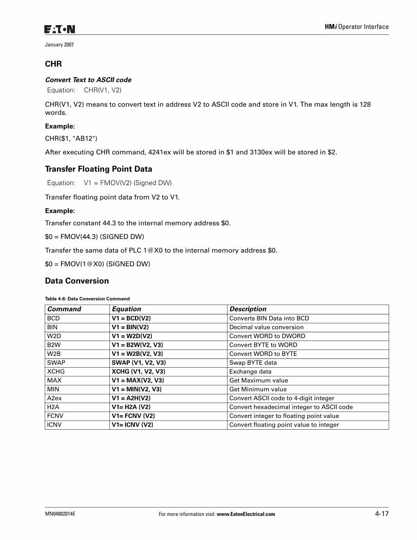
HMi Operator Interface
January 2007
CHR
Convert Text to ASCII code
CHR(V1, V2) means to convert text in address V2 to ASCII code and store in V1. The max length is 128 words.
Example:
CHR($1, "AB12")
After executing CHR command, 4241ex will be stored in $1 and 3130ex will be stored in $2.
Transfer Floating Point Data
Transfer floating point data from V2 to V1.
Example:
Transfer constant 44.3 to the internal memory address $0.
$0 = FMOV(44.3) (SIGNED DW)
Transfer the same data of PLC 1@X0 to the internal memory address $0.
$0 = FMOV(1@X0) (SIGNED DW)
Data Conversion
Equation: CHR(V1, V2)
Equation: V1 = FMOV(V2) (Signed DW)
Table 4-6: Data Conversion Command
Command Equation Description
BCD V1 = BCD(V2) Converts BIN Data into BCDBIN V1 = BIN(V2) Decimal value conversion W2D V1 = W2D(V2) Convert WORD to DWORDB2W V1 = B2W(V2, V3) Convert BYTE to WORDW2B V1 = W2B(V2, V3) Convert WORD to BYTESWAP SWAP (V1, V2, V3) Swap BYTE dataXCHG XCHG (V1, V2, V3) Exchange dataMAX V1 = MAX(V2, V3) Get Maximum valueMIN V1 = MIN(V2, V3) Get Minimum valueA2ex V1 = A2H(V2) Convert ASCII code to 4-digit integer H2A V1= H2A (V2) Convert hexadecimal integer to ASCII codeFCNV V1= FCNV (V2) Convert integer to floating point value ICNV V1= ICNV (V2) Convert floating point value to integer
MN04802014E For more information visit: www.EatonElectrical.com 4-17
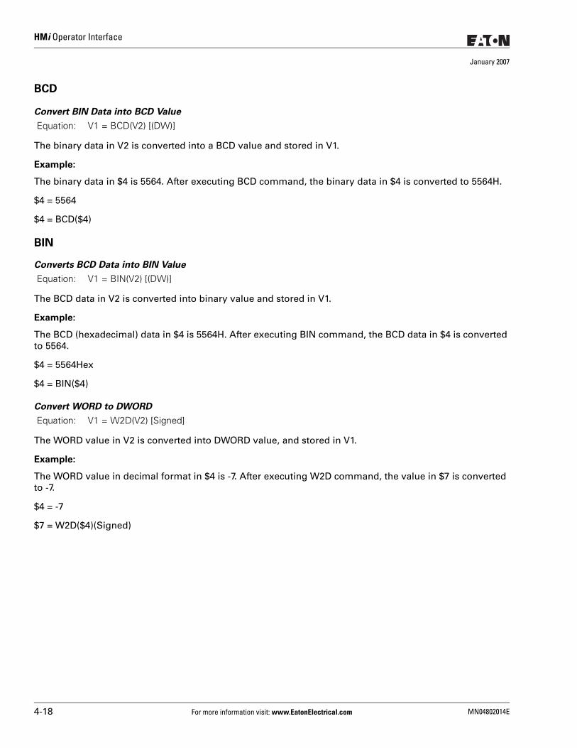
HMi Operator Interface
January 2007
BCD
Convert BIN Data into BCD Value
The binary data in V2 is converted into a BCD value and stored in V1.
Example:
The binary data in $4 is 5564. After executing BCD command, the binary data in $4 is converted to 5564H.
$4 = 5564
$4 = BCD($4)
BIN
Converts BCD Data into BIN Value
The BCD data in V2 is converted into binary value and stored in V1.
Example:
The BCD (hexadecimal) data in $4 is 5564H. After executing BIN command, the BCD data in $4 is converted to 5564.
$4 = 5564Hex
$4 = BIN($4)
Convert WORD to DWORD
The WORD value in V2 is converted into DWORD value, and stored in V1.
Example:
The WORD value in decimal format in $4 is -7. After executing W2D command, the value in $7 is converted to -7.
$4 = -7
$7 = W2D($4)(Signed)
Equation: V1 = BCD(V2) [(DW)]
Equation: V1 = BIN(V2) [(DW)]
Equation: V1 = W2D(V2) [Signed]
4-18 For more information visit: www.EatonElectrical.com MN04802014E
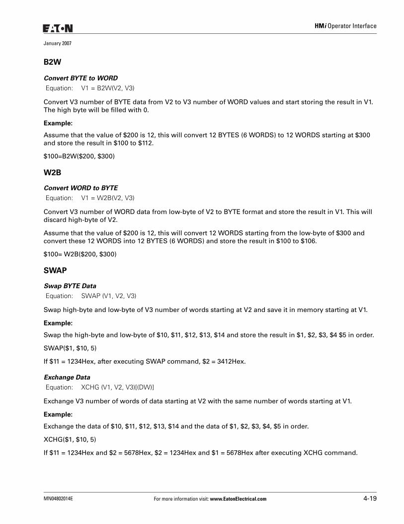
HMi Operator Interface
January 2007
B2W
Convert BYTE to WORD
Convert V3 number of BYTE data from V2 to V3 number of WORD values and start storing the result in V1. The high byte will be filled with 0.
Example:
Assume that the value of $200 is 12, this will convert 12 BYTES (6 WORDS) to 12 WORDS starting at $300 and store the result in $100 to $112.
$100=B2W($200, $300)
W2B
Convert WORD to BYTE
Convert V3 number of WORD data from low-byte of V2 to BYTE format and store the result in V1. This will discard high-byte of V2.
Assume that the value of $200 is 12, this will convert 12 WORDS starting from the low-byte of $300 and convert these 12 WORDS into 12 BYTES (6 WORDS) and store the result in $100 to $106.
$100= W2B($200, $300)
SWAP
Swap BYTE Data
Swap high-byte and low-byte of V3 number of words starting at V2 and save it in memory starting at V1.
Example:
Swap the high-byte and low-byte of $10, $11, $12, $13, $14 and store the result in $1, $2, $3, $4 $5 in order.
SWAP($1, $10, 5)
If $11 = 1234Hex, after executing SWAP command, $2 = 3412Hex.
Exchange Data
Exchange V3 number of words of data starting at V2 with the same number of words starting at V1.
Example:
Exchange the data of $10, $11, $12, $13, $14 and the data of $1, $2, $3, $4, $5 in order.
XCHG($1, $10, 5)
If $11 = 1234Hex and $2 = 5678Hex, $2 = 1234Hex and $1 = 5678Hex after executing XCHG command.
Equation: V1 = B2W(V2, V3)
Equation: V1 = W2B(V2, V3)
Equation: SWAP (V1, V2, V3)
Equation: XCHG (V1, V2, V3)[(DW)]
MN04802014E For more information visit: www.EatonElectrical.com 4-19
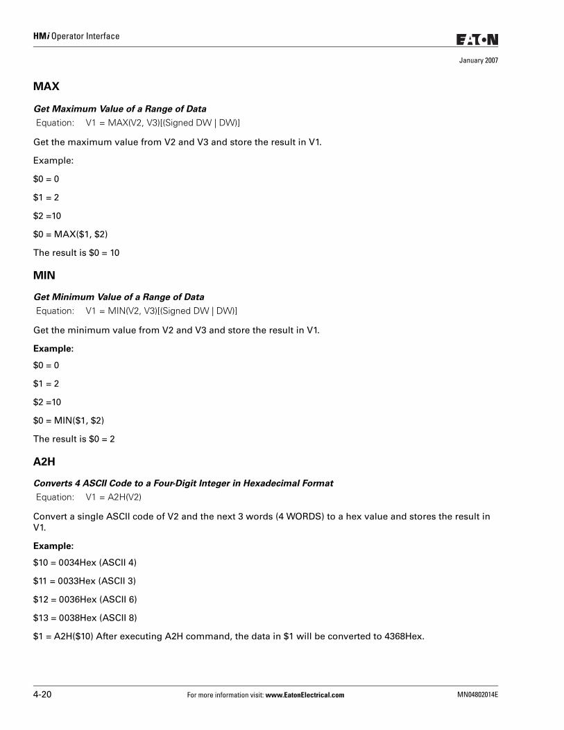
HMi Operator Interface
January 2007
MAX
Get Maximum Value of a Range of Data
Get the maximum value from V2 and V3 and store the result in V1.
Example:
$0 = 0
$1 = 2
$2 =10
$0 = MAX($1, $2)
The result is $0 = 10
MIN
Get Minimum Value of a Range of Data
Get the minimum value from V2 and V3 and store the result in V1.
Example:
$0 = 0
$1 = 2
$2 =10
$0 = MIN($1, $2)
The result is $0 = 2
A2H
Converts 4 ASCII Code to a Four-Digit Integer in Hexadecimal Format
Convert a single ASCII code of V2 and the next 3 words (4 WORDS) to a hex value and stores the result in V1.
Example:
$10 = 0034Hex (ASCII 4)
$11 = 0033Hex (ASCII 3)
$12 = 0036Hex (ASCII 6)
$13 = 0038Hex (ASCII 8)
$1 = A2H($10) After executing A2H command, the data in $1 will be converted to 4368Hex.
Equation: V1 = MAX(V2, V3)[(Signed DW | DW)]
Equation: V1 = MIN(V2, V3)[(Signed DW | DW)]
Equation: V1 = A2H(V2)
4-20 For more information visit: www.EatonElectrical.com MN04802014E
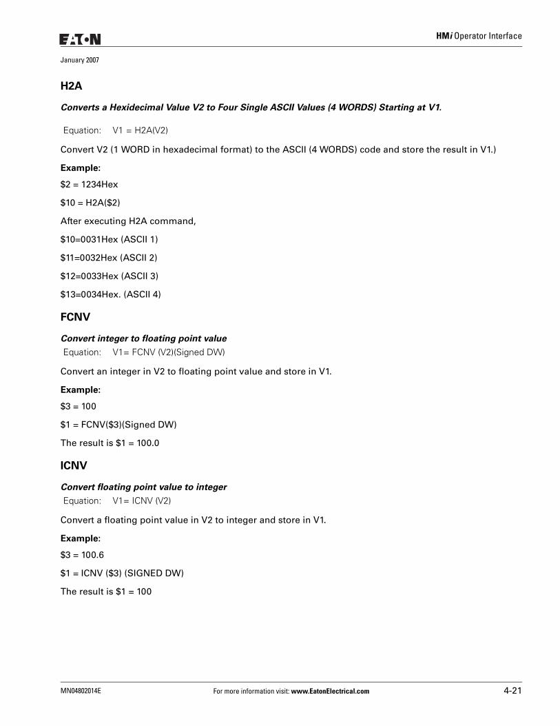
HMi Operator Interface
January 2007
H2A
Converts a Hexidecimal Value V2 to Four Single ASCII Values (4 WORDS) Starting at V1.
Convert V2 (1 WORD in hexadecimal format) to the ASCII (4 WORDS) code and store the result in V1.)
Example:
$2 = 1234Hex
$10 = H2A($2)
After executing H2A command,
$10=0031Hex (ASCII 1)
$11=0032Hex (ASCII 2)
$12=0033Hex (ASCII 3)
$13=0034Hex. (ASCII 4)
FCNV
Convert integer to floating point value
Convert an integer in V2 to floating point value and store in V1.
Example:
$3 = 100
$1 = FCNV($3)(Signed DW)
The result is $1 = 100.0
ICNV
Convert floating point value to integer
Convert a floating point value in V2 to integer and store in V1.
Example:
$3 = 100.6
$1 = ICNV ($3) (SIGNED DW)
The result is $1 = 100
Equation: V1 = H2A(V2)
Equation: V1= FCNV (V2)(Signed DW)
Equation: V1= ICNV (V2)
MN04802014E For more information visit: www.EatonElectrical.com 4-21
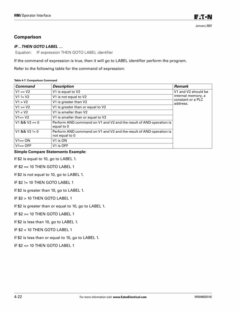
HMi Operator Interface
January 2007
Comparison
IF…THEN GOTO LABEL …
If the command of expression is true, then it will go to LABEL identifier perform the program.
Refer to the following table for the command of expression:
Simple Compare Statements Example:
If $2 is equal to 10, go to LABEL 1.
IF $2 == 10 THEN GOTO LABEL 1
If $2 is not equal to 10, go to LABEL 1.
IF $2 != 10 THEN GOTO LABEL 1
If $2 is greater than 10, go to LABEL 1.
IF $2 > 10 THEN GOTO LABEL 1
If $2 is greater than or equal to 10, go to LABEL 1.
IF $2 >= 10 THEN GOTO LABEL 1
If $2 is less than 10, go to LABEL 1.
IF $2 < 10 THEN GOTO LABEL 1
If $2 is less than or equal to 10, go to LABEL 1.
IF $2 <= 10 THEN GOTO LABEL 1
Equation: IF expression THEN GOTO LABEL identifier
Table 4-7: Comparison Command
Command Description Remark
V1 == V2 V1 is equal to V2 V1 and V2 should be internal memory, a constant or a PLC address.
V1 != V2 V1 is not equal to V2V1 > V2 V1 is greater than V2V1 >= V2 V1 is greater than or equal to V2V1 < V2 V1 is smaller than V2V1<= V2 V1 is smaller than or equal to V2V1 && V2 == 0 Perform AND command on V1 and V2 and the result of AND operation is
equal to 0V1 && V2 != 0 Perform AND command on V1 and V2 and the result of AND operation is
not equal to 0V1== ON V1 is ONV1== OFF V1 is OFF
4-22 For more information visit: www.EatonElectrical.com MN04802014E
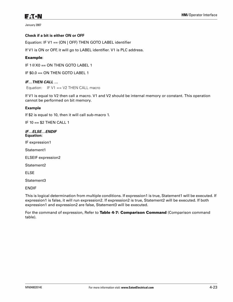
HMi Operator Interface
January 2007
Check if a bit is either ON or OFF
Equation: IF V1 == {ON | OFF} THEN GOTO LABEL identifier
If V1 is ON or OFF, it will go to LABEL identifier. V1 is PLC address.
Example:
IF 1@X0 == ON THEN GOTO LABEL 1
IF $0.0 == ON THEN GOTO LABEL 1
IF…THEN CALL …
If V1 is equal to V2 then call a macro. V1 and V2 should be internal memory or constant. This operation cannot be performed on bit memory.
Example
If $2 is equal to 10, then it will call sub-macro 1.
IF 10 == $2 THEN CALL 1
IF…ELSE…ENDIFEquation:
IF expression1
Statement1
ELSEIF expression2
Statement2
ELSE
Statement3
ENDIF
This is logical determination from multiple conditions. If expression1 is true, Statement1 will be executed. If expression1 is false, it will run expression2. If expression2 is true, Statement2 will be executed. If both expression1 and expression2 are false, Statement3 will be executed.
For the command of expression, Refer to Table 4-7: Comparison Command (Comparison command table).
Equation: IF V1 == V2 THEN CALL macro
MN04802014E For more information visit: www.EatonElectrical.com 4-23
HMi Operator Interface
January 2007
Example:
If $1< 100, $1 = $1 + 1 is executed. Otherwise $1 = $1 + 10 is executed.
IF $1 < 100
$1 = $1 + 1
ELSE
$1 = $1 + 10
ENDIF
If $1 i< 5 then $2 = 5, if $1 > 10 then $2 = 10 otherwise $2 = $1.
IF $1 < 5
$2 = 5
ELSEIF $1 > 10
$2 = 10
ELSE
42 = $1
ENDIF
There are five types for flow control: GOTO, LABEL, CALL...RET, FOR…NEXT and END.
GOTO
Unconditionally go to a specific Label. GOTO command will jump to designated label like Label V1 uncon-ditionally.
Go to the internal designated Label V1 in the program unconditionally.
Example:
Go to the position of designated Label 2 and continue to execute the program unconditionally.
GOTO LABEL 2
...
...
...
LABEL 2
Equation: GOTO LABEL V1
4-24 For more information visit: www.EatonElectrical.com MN04802014E
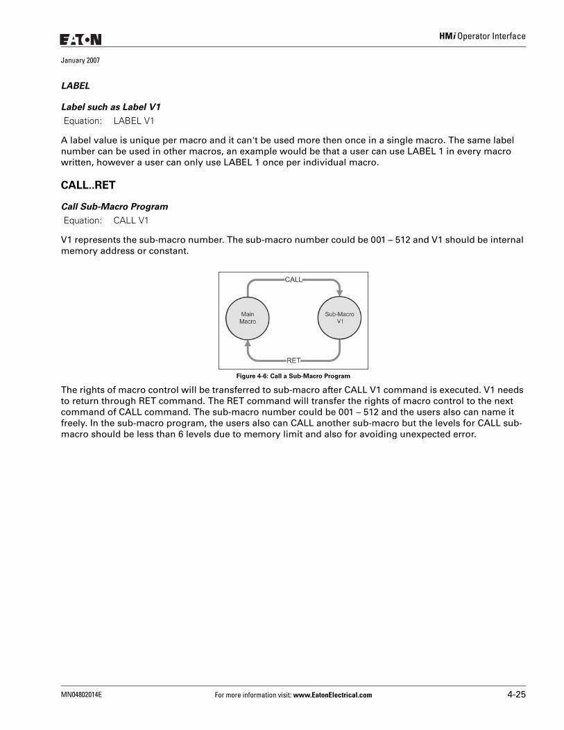
HMi Operator Interface
January 2007
LABEL
Label such as Label V1
A label value is unique per macro and it can't be used more then once in a single macro. The same label number can be used in other macros, an example would be that a user can use LABEL 1 in every macro written, however a user can only use LABEL 1 once per individual macro.
CALL..RET
Call Sub-Macro Program
V1 represents the sub-macro number. The sub-macro number could be 001 – 512 and V1 should be internal memory address or constant.
Figure 4-6: Call a Sub-Macro Program
The rights of macro control will be transferred to sub-macro after CALL V1 command is executed. V1 needs to return through RET command. The RET command will transfer the rights of macro control to the next command of CALL command. The sub-macro number could be 001 – 512 and the users also can name it freely. In the sub-macro program, the users also can CALL another sub-macro but the levels for CALL sub-macro should be less than 6 levels due to memory limit and also for avoiding unexpected error.
Equation: LABEL V1
Equation: CALL V1
MN04802014E For more information visit: www.EatonElectrical.com 4-25
HMi Operator Interface
January 2007
FOR…NEXT
Program LoopEquation:
FOR V1 Statement NEXT
It is for nested loops. ”FOR” is the start of the loop and ”NEXT” is the end of the loop. The nested loop can be up to 5 levels max. V1 can be the internal memory or constant. When this command is executed, the number of V1 Statement will be executed continuously. Statement is the combination of a section of macro commands and also can be within the nested loop. The users can change the V1 value through command, but the number of times cannot be changed.
Example:
$10 = 10
$1 = 0
FOR $10
$1 = $1 + 1
NEXT
After the operation, the result is $1 = 10
If a $10 = 2 is inserted between the FOR and the NEXT in the above macro, the FOR … NEXT loop will still loop 10 times even though $10 is changed to a value of 2 the first pass through the loop.
END
End the macro
Equation: Statements1 END Statements2
End command is used to end the macro program and all statements after the END command will not be executed. If this command is in a main macro then the program will go to the first line again and begin execution, if this command is in a sub-macro then the sub-macro will end and the program will return to the previous program.
Example:
$1 = 10
$1 = $1 + 1
END
$1 = $1 + 1
After the operation, the result is $1 = 11, not $1 = 12 as the END command has ended the macro program.
4-26 For more information visit: www.EatonElectrical.com MN04802014E
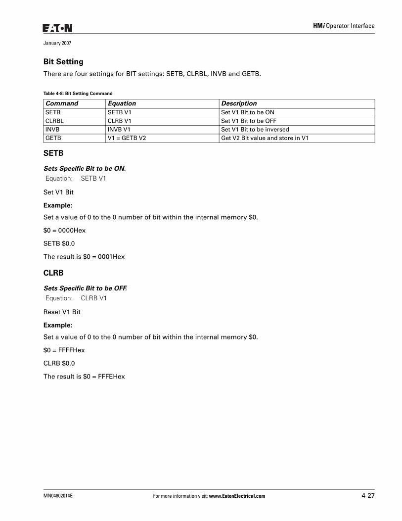
HMi Operator Interface
January 2007
Bit Setting
There are four settings for BIT settings: SETB, CLRBL, INVB and GETB.
SETB
Sets Specific Bit to be ON.
Set V1 Bit
Example:
Set a value of 0 to the 0 number of bit within the internal memory $0.
$0 = 0000Hex
SETB $0.0
The result is $0 = 0001Hex
CLRB
Sets Specific Bit to be OFF.
Reset V1 Bit
Example:
Set a value of 0 to the 0 number of bit within the internal memory $0.
$0 = FFFFHex
CLRB $0.0
The result is $0 = FFFEHex
Table 4-8: Bit Setting Command
Command Equation Description
SETB SETB V1 Set V1 Bit to be ONCLRBL CLRB V1 Set V1 Bit to be OFFINVB INVB V1 Set V1 Bit to be inversedGETB V1 = GETB V2 Get V2 Bit value and store in V1
Equation: SETB V1
Equation: CLRB V1
MN04802014E For more information visit: www.EatonElectrical.com 4-27
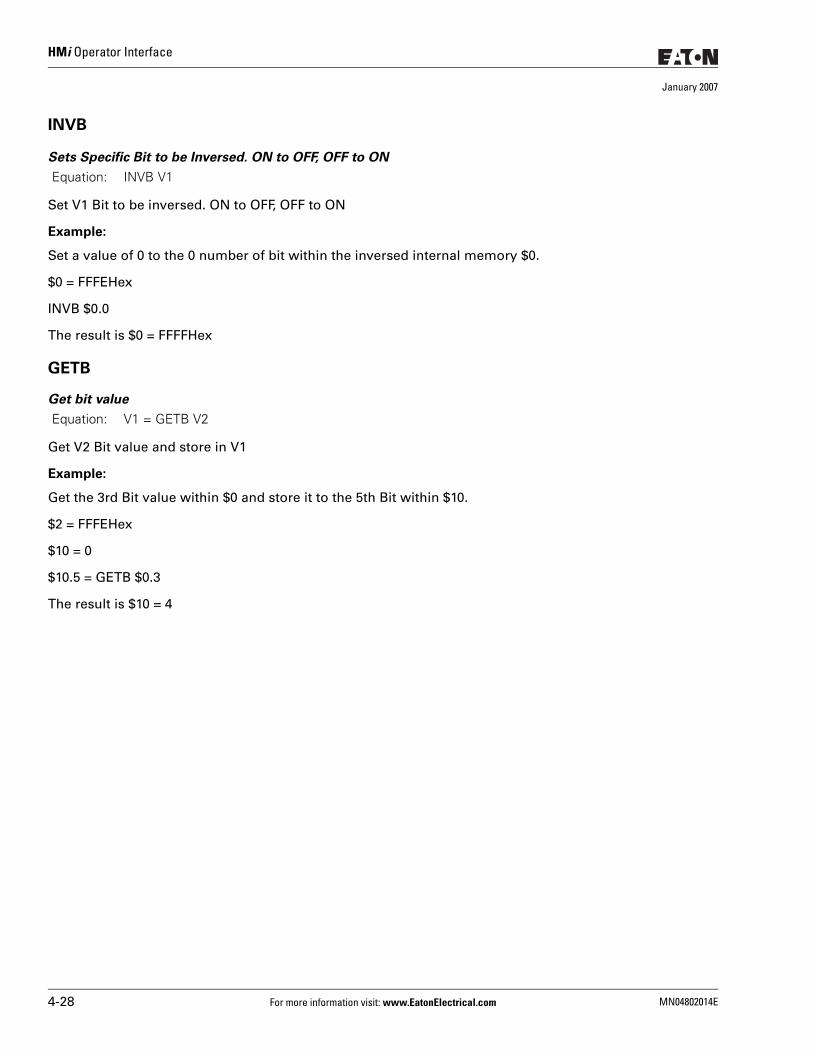
HMi Operator Interface
January 2007
INVB
Sets Specific Bit to be Inversed. ON to OFF, OFF to ON
Set V1 Bit to be inversed. ON to OFF, OFF to ON
Example:
Set a value of 0 to the 0 number of bit within the inversed internal memory $0.
$0 = FFFEHex
INVB $0.0
The result is $0 = FFFFHex
GETB
Get bit value
Get V2 Bit value and store in V1
Example:
Get the 3rd Bit value within $0 and store it to the 5th Bit within $10.
$2 = FFFEHex
$10 = 0
$10.5 = GETB $0.3
The result is $10 = 4
Equation: INVB V1
Equation: V1 = GETB V2
4-28 For more information visit: www.EatonElectrical.com MN04802014E
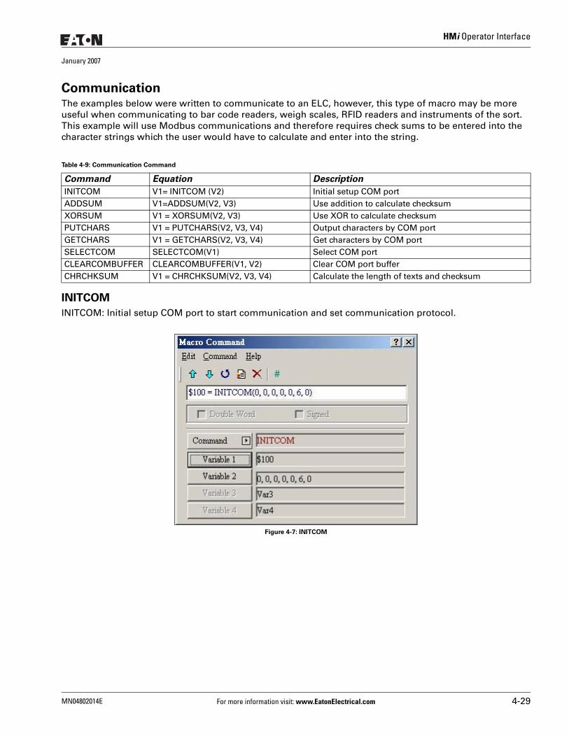
HMi Operator Interface
January 2007
CommunicationThe examples below were written to communicate to an ELC, however, this type of macro may be more useful when communicating to bar code readers, weigh scales, RFID readers and instruments of the sort. This example will use Modbus communications and therefore requires check sums to be entered into the character strings which the user would have to calculate and enter into the string.
INITCOM
INITCOM: Initial setup COM port to start communication and set communication protocol.
Figure 4-7: INITCOM
Table 4-9: Communication Command
Command Equation Description
INITCOM V1= INITCOM (V2) Initial setup COM portADDSUM V1=ADDSUM(V2, V3) Use addition to calculate checksumXORSUM V1 = XORSUM(V2, V3) Use XOR to calculate checksumPUTCHARS V1 = PUTCHARS(V2, V3, V4) Output characters by COM portGETCHARS V1 = GETCHARS(V2, V3, V4) Get characters by COM portSELECTCOM SELECTCOM(V1) Select COM portCLEARCOMBUFFER CLEARCOMBUFFER(V1, V2) Clear COM port bufferCHRCHKSUM V1 = CHRCHKSUM(V2, V3, V4) Calculate the length of texts and checksum
MN04802014E For more information visit: www.EatonElectrical.com 4-29
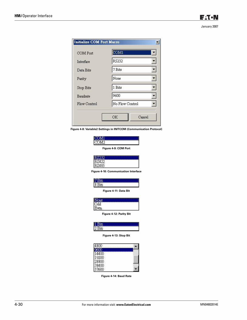
HMi Operator Interface
January 2007
Figure 4-8: Variable2 Settings in INITCOM (Communication Protocol)
Figure 4-9: COM Port
Figure 4-10: Communication Interface
Figure 4-11: Data Bit
Figure 4-12: Parity Bit
Figure 4-13: Stop Bit
Figure 4-14: Baud Rate
4-30 For more information visit: www.EatonElectrical.com MN04802014E
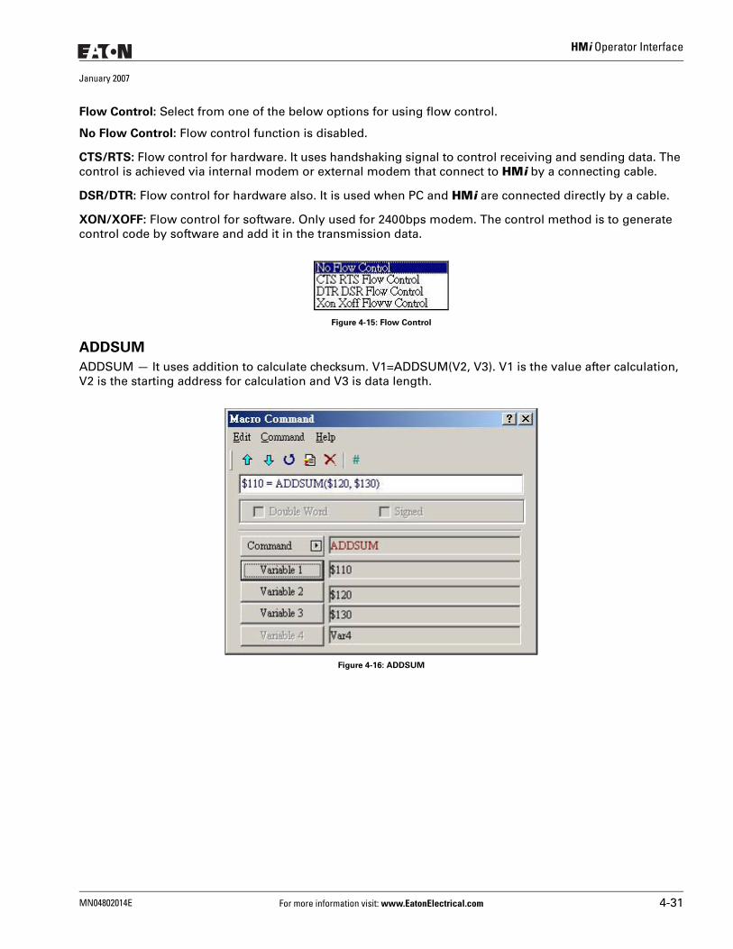
HMi Operator Interface
January 2007
Flow Control: Select from one of the below options for using flow control.
No Flow Control: Flow control function is disabled.
CTS/RTS: Flow control for hardware. It uses handshaking signal to control receiving and sending data. The control is achieved via internal modem or external modem that connect to HMi by a connecting cable.
DSR/DTR: Flow control for hardware also. It is used when PC and HMi are connected directly by a cable.
XON/XOFF: Flow control for software. Only used for 2400bps modem. The control method is to generate control code by software and add it in the transmission data.
Figure 4-15: Flow Control
ADDSUM
ADDSUM — It uses addition to calculate checksum. V1=ADDSUM(V2, V3). V1 is the value after calculation, V2 is the starting address for calculation and V3 is data length.
Figure 4-16: ADDSUM
MN04802014E For more information visit: www.EatonElectrical.com 4-31
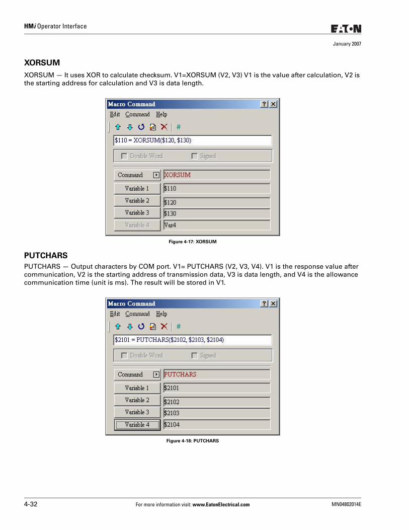
HMi Operator Interface
January 2007
XORSUM
XORSUM — It uses XOR to calculate checksum. V1=XORSUM (V2, V3) V1 is the value after calculation, V2 is the starting address for calculation and V3 is data length.
Figure 4-17: XORSUM
PUTCHARS
PUTCHARS — Output characters by COM port. V1= PUTCHARS (V2, V3, V4). V1 is the response value after communication, V2 is the starting address of transmission data, V3 is data length, and V4 is the allowance communication time (unit is ms). The result will be stored in V1.
Figure 4-18: PUTCHARS
4-32 For more information visit: www.EatonElectrical.com MN04802014E
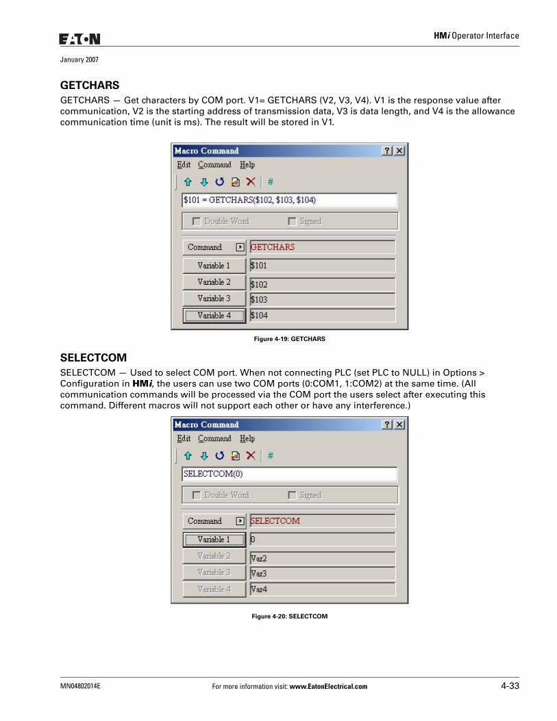
HMi Operator Interface
January 2007
GETCHARS
GETCHARS — Get characters by COM port. V1= GETCHARS (V2, V3, V4). V1 is the response value after communication, V2 is the starting address of transmission data, V3 is data length, and V4 is the allowance communication time (unit is ms). The result will be stored in V1.
Figure 4-19: GETCHARS
SELECTCOM
SELECTCOM — Used to select COM port. When not connecting PLC (set PLC to NULL) in Options > Configuration in HMi, the users can use two COM ports (0:COM1, 1:COM2) at the same time. (All communication commands will be processed via the COM port the users select after executing this command. Different macros will not support each other or have any interference.)
Figure 4-20: SELECTCOM
MN04802014E For more information visit: www.EatonElectrical.com 4-33
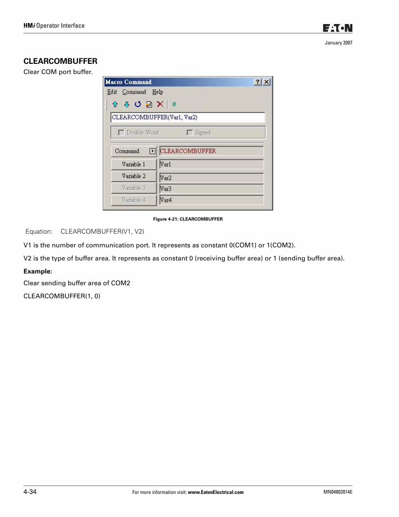
HMi Operator Interface
January 2007
CLEARCOMBUFFER
Clear COM port buffer.
Figure 4-21: CLEARCOMBUFFER
V1 is the number of communication port. It represents as constant 0(COM1) or 1(COM2).
V2 is the type of buffer area. It represents as constant 0 (receiving buffer area) or 1 (sending buffer area).
Example:
Clear sending buffer area of COM2
CLEARCOMBUFFER(1, 0)
Equation: CLEARCOMBUFFER(V1, V2)
4-34 For more information visit: www.EatonElectrical.com MN04802014E
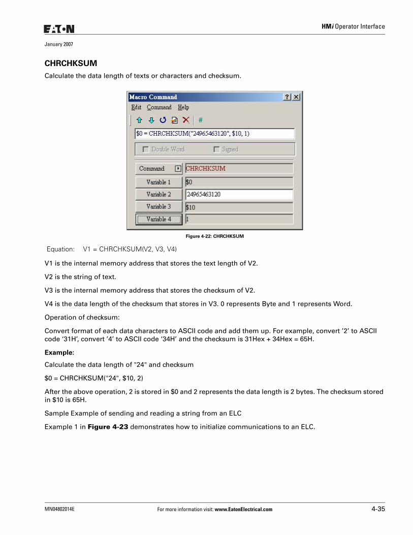
HMi Operator Interface
January 2007
CHRCHKSUM
Calculate the data length of texts or characters and checksum.
Figure 4-22: CHRCHKSUM
V1 is the internal memory address that stores the text length of V2.
V2 is the string of text.
V3 is the internal memory address that stores the checksum of V2.
V4 is the data length of the checksum that stores in V3. 0 represents Byte and 1 represents Word.
Operation of checksum:
Convert format of each data characters to ASCII code and add them up. For example, convert ’2’ to ASCII code ‘31H’, convert ’4’ to ASCII code ‘34H’ and the checksum is 31Hex + 34Hex = 65H.
Example:
Calculate the data length of "24" and checksum
$0 = CHRCHKSUM("24", $10, 2)
After the above operation, 2 is stored in $0 and 2 represents the data length is 2 bytes. The checksum stored in $10 is 65H.
Sample Example of sending and reading a string from an ELC
Example 1 in Figure 4-23 demonstrates how to initialize communications to an ELC.
Equation: V1 = CHRCHKSUM(V2, V3, V4)
MN04802014E For more information visit: www.EatonElectrical.com 4-35
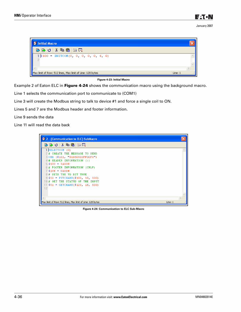
HMi Operator Interface
January 2007
Figure 4-23: Initial Macro
Example 2 of Eaton ELC in Figure 4-24 shows the communication macro using the background macro.
Line 1 selects the communication port to communicate to (COM1)
Line 3 will create the Modbus string to talk to device #1 and force a single coil to ON.
Lines 5 and 7 are the Modbus header and footer information.
Line 9 sends the data
Line 11 will read the data back
Figure 4-24: Communication to ELC Sub-Macro
4-36 For more information visit: www.EatonElectrical.com MN04802014E
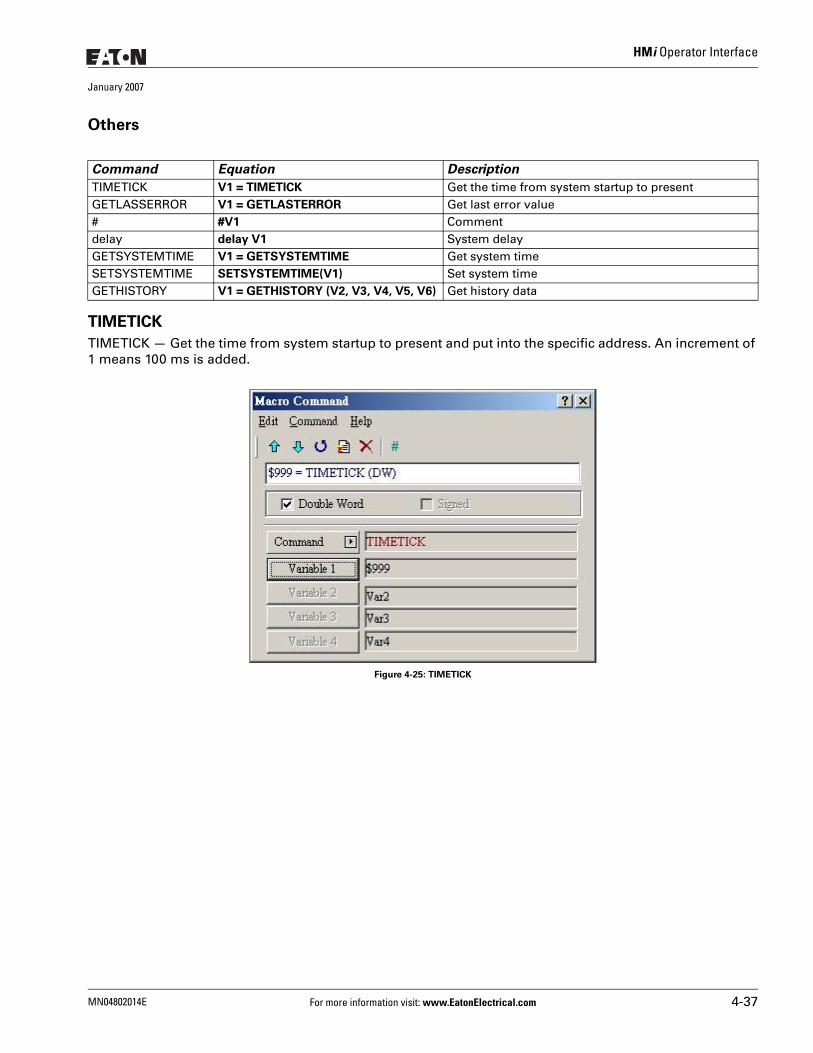
HMi Operator Interface
January 2007
Others
TIMETICK
TIMETICK — Get the time from system startup to present and put into the specific address. An increment of 1 means 100 ms is added.
Figure 4-25: TIMETICK
Command Equation Description
TIMETICK V1 = TIMETICK Get the time from system startup to presentGETLASSERROR V1 = GETLASTERROR Get last error value# #V1 Commentdelay delay V1 System delayGETSYSTEMTIME V1 = GETSYSTEMTIME Get system timeSETSYSTEMTIME SETSYSTEMTIME(V1) Set system timeGETHISTORY V1 = GETHISTORY (V2, V3, V4, V5, V6) Get history data
MN04802014E For more information visit: www.EatonElectrical.com 4-37
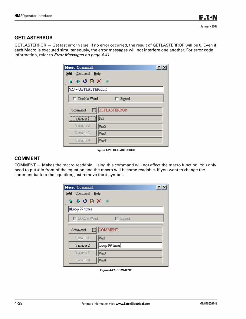
HMi Operator Interface
January 2007
GETLASTERROR
GETLASTERROR — Get last error value. If no error occurred, the result of GETLASTERROR will be 0. Even if each Macro is executed simultaneously, the error messages will not interfere one another. For error code information, refer to Error Messages on page 4-41.
Figure 4-26: GETLASTERROR
COMMENT
COMMENT — Makes the macro readable. Using this command will not affect the macro function. You only need to put # in front of the equation and the macro will become readable. If you want to change the comment back to the equation, just remove the # symbol.
Figure 4-27: COMMENT
4-38 For more information visit: www.EatonElectrical.com MN04802014E
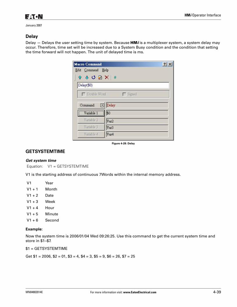
HMi Operator Interface
January 2007
Delay
Delay — Delays the user setting time by system. Because HMi is a multiplexer system, a system delay may occur. Therefore, time set will be increased due to a System Busy condition and the condition that setting the time forward will not happen. The unit of delayed time is ms.
Figure 4-28: Delay
GETSYSTEMTIME
Get system time
V1 is the starting address of continuous 7Words within the internal memory address.
Example:
Now the system time is 2006/01/04 Wed 09:26:25. Use this command to get the current system time and store in $1–$7.
$1 = GETSYSTEMTIME
Get $1 = 2006, $2 = 01, $3 = 4, $4 = 3, $5 = 9, $6 = 26, $7 = 25
Equation: V1 = GETSYSTEMTIME
V1 Year
V1 + 1 Month
V1 + 2 Date
V1 + 3 Week
V1 + 4 Hour
V1 + 5 Minute
V1 + 6 Second
MN04802014E For more information visit: www.EatonElectrical.com 4-39
HMi Operator Interface
January 2007
SETSYSTEMTIME
Set system time
V1 is the starting address of continuous 7Words within the internal memory address.
Example:
Set the current system time as 2006/01/04 Wed 09:26:25.
$1 = 2006
$2 = 1
$3 = 4
$4 = 3
$5 = 9
$6 = 26
$7 = 25
SETSYSTEMTIME($1)
GETHISTORY
Get History Data
V1 is the internal memory address where store the data length.
V2 is the internal memory, constant, the buffer number of history buffer area.
V3 is the internal memory, constant, the starting address for sampling.
V4 is the internal memory, constant, the points for reading
V5 is the internal memory, PLC address, the address where store the data
V6 is the internal memory, constant, the data type for reading
0: Data, 1: Time, 2: Time and Data
Equation: SETSYSTEMTIME(V1)
V1 Year
V1 + 1 Month
V1 + 2 Date
V1 + 3 Week
V1 + 4 Hour
V1 + 5 Minute
V1 + 6 Second
Equation: V1 = GETHISTORY (V2, V3, V4, V5, V6)
4-40 For more information visit: www.EatonElectrical.com MN04802014E
HMi Operator Interface
January 2007
Error MessagesWhen compiling, Error Messages will show in the output window, which are easy to find. Some errors occur because of user carelessness, others because users fail to enter some commands, but they may be difficult to find in long Macro. To help the users debug and find problems, the HMi Macro provides error messages to show what the error is. To prevent logic errors, you should be aware of what you are doing and try to avoid making this kind of mistake.
Error Messages When Editing
Code – 100: LABEL cannot be foundThere is no such LABEL that GOTO designates.
Code – 101: Recursion occursThis error message usually occurs in a sub-macro. The ability of a sub-macro to CALL itself is called recursion, no matter if it is called directly or indirectly. Basically, recursion cannot be adopted for a sub-macro. You can use GOTO or FOR (infinite times) to replace it.
Code – 102: More than 3 nested FOR is usedThis error message statements are to warn you not to use more than 3 nested FOR commands. The purpose is to avoid insufficient memory. The users can use GOTO or IF to replace it.
Code – 103: Sub-macro does not existThis error message means that there is no sub-macro in the program. For example, CALL 5 means CALL sub-macro 5. If you do not edit sub-macro 5 in the program, this error message will display to warn the users. The purpose is to warn the users to be more careful when editing (reduce input error or avoid forgetting to edit the corresponding sub-macro) and prevent unexpected error.
Code – 104: Number of NEXT is less than the number of FORNumbers of NEXT and FOR should match. This error code is used to remind you to find out the missing NEXT.
Code –105: Number of FOR is less than the number of NEXTNumbers of FOR and NEXT should match. This error code is used to remind the user if there is any missing FOR.
Code–106: Repeated LABELThis error message means that there are repeated LABELs in the same Macro. The program will be confusing with that. This may be caused by carelessness (an input error or forgetting to edit the corresponding sub-macro), and you will get an error message during editing to help you avoid unexpected error.
Code–107: There is RET in MacroThis error message means that there is RET command in Macro. The RET command should be used for sub-macro to return program. But in Macro, it should use END not RET.
MN04802014E For more information visit: www.EatonElectrical.com 4-41
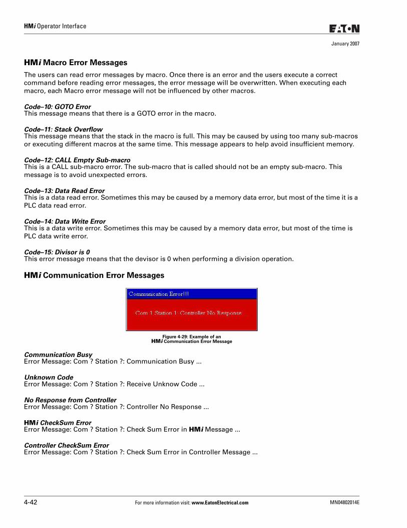
HMi Operator Interface
January 2007
HMi Macro Error Messages
The users can read error messages by macro. Once there is an error and the users execute a correct command before reading error messages, the error message will be overwritten. When executing each macro, each Macro error message will not be influenced by other macros.
Code–10: GOTO ErrorThis message means that there is a GOTO error in the macro.
Code–11: Stack OverflowThis message means that the stack in the macro is full. This may be caused by using too many sub-macros or executing different macros at the same time. This message appears to help avoid insufficient memory.
Code–12: CALL Empty Sub-macroThis is a CALL sub-macro error. The sub-macro that is called should not be an empty sub-macro. This message is to avoid unexpected errors.
Code–13: Data Read ErrorThis is a data read error. Sometimes this may be caused by a memory data error, but most of the time it is a PLC data read error.
Code–14: Data Write ErrorThis is a data write error. Sometimes this may be caused by a memory data error, but most of the time is PLC data write error.
Code–15: Divisor is 0This error message means that the devisor is 0 when performing a division operation.
HMi Communication Error Messages
Figure 4-29: Example of anHMi Communication Error Message
Communication BusyError Message: Com ? Station ?: Communication Busy ...
Unknown CodeError Message: Com ? Station ?: Receive Unknow Code ...
No Response from ControllerError Message: Com ? Station ?: Controller No Response ...
HMi CheckSum ErrorError Message: Com ? Station ?: Check Sum Error in HMi Message ...
Controller CheckSum ErrorError Message: Com ? Station ?: Check Sum Error in Controller Message ...
4-42 For more information visit: www.EatonElectrical.com MN04802014E
HMi Operator Interface
January 2007
Incorrect Command
Error Message: Com %d Station %d: Command Can Not be Executed ...
Incorrect AddressError Message: Com ? Station ?: Address Fault ...
Incorrect ValueError Message: Com ? Station ?: Value is Incorrect ...
Controller is BusyError Message: Com ? Station ?: Controller is Busy ...
CTS Signal FailError Message: Com ? Station ?: CTS Signal Fail ...
No Such Resource in ControllerError Message: Com ? Station ?: No Such Resource ...
No Such Service in ControllerError Message: Com ? Station ?: No Such Service ...
Must RetryError Message: Com ? Station ?: Must Retry ...
HMi Station Number ErrorError Message: Com ? Station ?: HMi Station Number Error ...
Controller Station Number ErrorError Message: Com ? Station ?: Controller Station Number Error ...
UART Communication ErrorError Message: Com ? Station ?: UART Communication Error ...
Other Communication ErrorError Message: Com? Station ?: Other Communication Error ...
MN04802014E For more information visit: www.EatonElectrical.com 4-43

HMi Operator Interface
January 2007
4-44 For more information visit: www.EatonElectrical.com MN04802014E
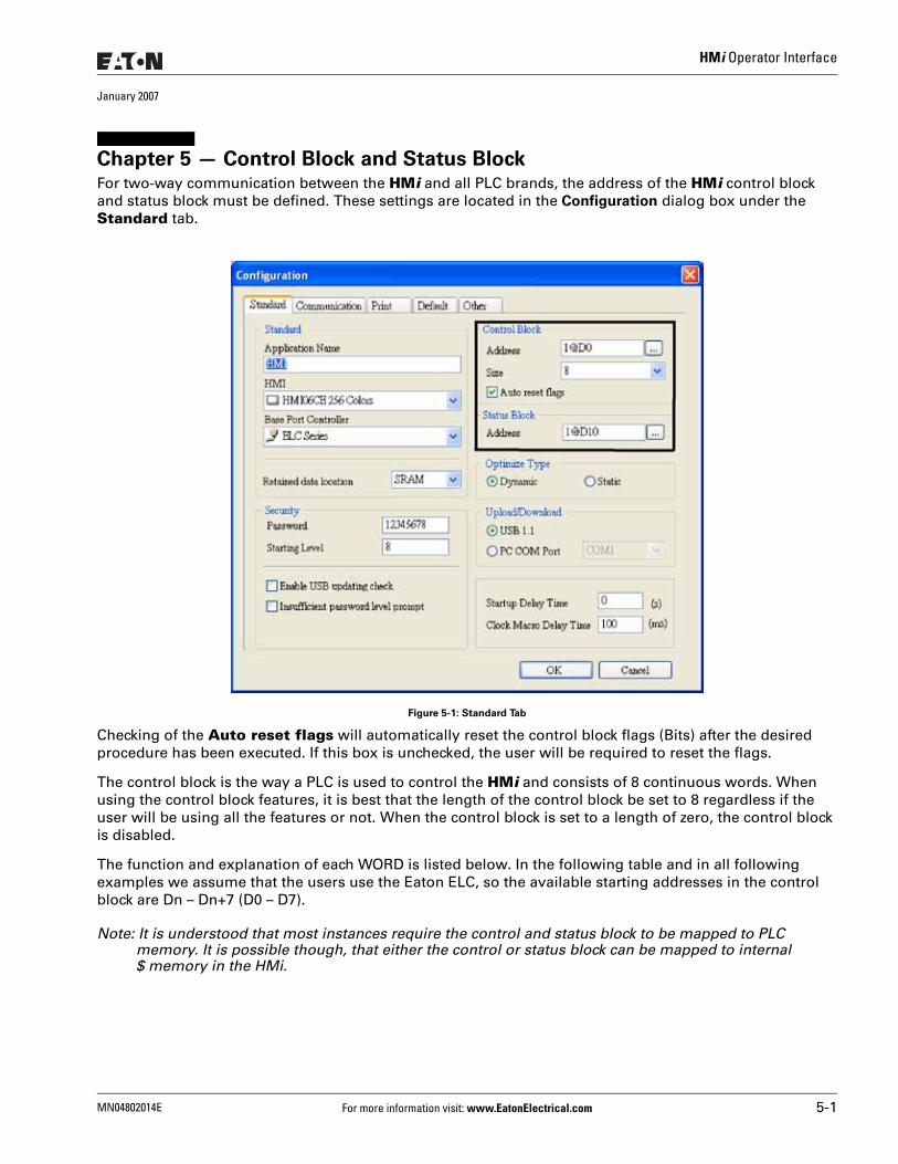
HMi Operator Interface
January 2007
Chapter 5 — Control Block and Status BlockFor two-way communication between the HMi and all PLC brands, the address of the HMi control block and status block must be defined. These settings are located in the Configuration dialog box under the Standard tab.
Figure 5-1: Standard Tab
Checking of the Auto reset flags will automatically reset the control block flags (Bits) after the desired procedure has been executed. If this box is unchecked, the user will be required to reset the flags.
The control block is the way a PLC is used to control the HMi and consists of 8 continuous words. When using the control block features, it is best that the length of the control block be set to 8 regardless if the user will be using all the features or not. When the control block is set to a length of zero, the control block is disabled.
The function and explanation of each WORD is listed below. In the following table and in all following examples we assume that the users use the Eaton ELC, so the available starting addresses in the control block are Dn – Dn+7 (D0 – D7).
Note: It is understood that most instances require the control and status block to be mapped to PLC memory. It is possible though, that either the control or status block can be mapped to internal $ memory in the HMi.
MN04802014E For more information visit: www.EatonElectrical.com 5-1
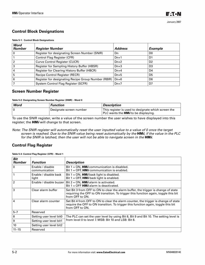
HMi Operator Interface
January 2007
Control Block Designations
Screen Number Register
To use the SNIR register, write a value of the screen number the user wishes to have displayed into this register; the HMi will change to that screen.
Note: The SNIR register will automatically reset the user inputted value to a value of 0 once the target screen is reached. Due to the SNIR value being reset automatically by the HMi, if the value in the PLC for the SNIR is latched, then the user will not be able to navigate screen in the HMi.
Control Flag Register
Table 5-1: Control Block Designations
Word Number Register Number Address Example
0 Register for designating Screen Number (SNIR) Dn D01 Control Flag Register (CFR) Dn+1 D12 Curve Control Register (CUCR) Dn+2 D23 Register for Sampling History Buffer (HBSR) Dn+3 D34 Register for Clearing History Buffer (HBCR) Dn+4 D45 Recipe Control Register (RECR) Dn+5 D56 Register for designating Recipe Group Number (RBIR) Dn+6 D67 System Control Flag Register (SCFR) Dn+7 D7
Table 5-2: Designating Screen Number Register (SNIR) - Word 0
Word Function Description
0 Designate screen number This register is used to designate which screen the PLC wants the HMi to be displaying.
Table 5-3: Control Flag Register (CFR) - Word 1
Bit Number Function Description
0 Enable / disable communication
Bit 1 = ON, HMi communication is disabled.Bit 1 = OFF, HMi communication is enabled.
1 Enable / disable back light
Bit 1 = ON, HMi back light is disabled.Bit 1 = OFF, HMi back light is enabled.
2 Enable / disable buzzer Bit 2 = ON, HMi alarm is activated.Bit 1 = OFF HMi alarm is deactivated.
3 Clear alarm buffer Set Bit 3 from OFF to ON to clear the alarm buffer, the trigger is change of state requiring the OFF to ON transition. To trigger this function again, toggle this bit from OFF to ON.
4 Clear alarm counter Set Bit 4 from OFF to ON to clear the alarm counter, the trigger is change of state require the OFF to ON transition. To trigger this function again, toggle this bit from OFF to ON.
5–7 Reserved8 Setting user level bit0 The PLC can set the user level by using Bit 8, Bit 9 and Bit 10. The setting level is
from level 0 to level 7. MSB: Bit 10 and LSB: Bit 8.9 Setting user level bit110 Setting user level bit211–15 Reserved
5-2 For more information visit: www.EatonElectrical.com MN04802014E

HMi Operator Interface
January 2007
Bit 0 is used to enable or disable the HMi communications, by default this value is set to 0 which is enabled. By checking the Communication Interrupt check box under the Communication tab of the Configuration dialog box when communications is lost this bit will set ON automatically and the user can clear it to re-enable communications. If the Communication Interrupt check box is unchecked, this flag is disabled.
Bit 1 is used to enable or disable the HMi back light. When the back light is disabled the screen is not viewable, however the elements are still active and pressing the screen can activate the elements. It is important that if the back light is disabled, that the user be aware that the screen, even though not viewable, is still active.
Bit 2 is used to turn the audible alarm either on or off. When this bit is true, the alarm will sound and when this bit is false the alarm will be silent. If the user wished to enable or disable the "beep" when the screen is pressed then this is performed by pressing an holding the SYS button on the HMi and disabling the Buzzer under Settings.
Bit 3 is used to clear the alarm buffer. When an alarm history table is used, setting of this bit will clear all contents inside of that table. The bit is automatically reset after the bit is set and the table is cleared.
Bit 4 is used to clear the alarm counter. When an alarm frequency table is used, setting of this bit will clear the values for the alarms. The bit is automatically reset after the bit is set and the table counters are cleared.
Bits 8 - 10 are used to set the user level of the HMi. Since the user level is the high byte of the word, simply use a masked write from the PLC to set to level 0 to 7. Whatever the value represented in the bits will be the user level of the HMi and the only place to change the user level will be the PLC. If certain elements need to have specific user level, set that level in the element since the PLC sets the user level globally in the HMi.
MN04802014E For more information visit: www.EatonElectrical.com 5-3
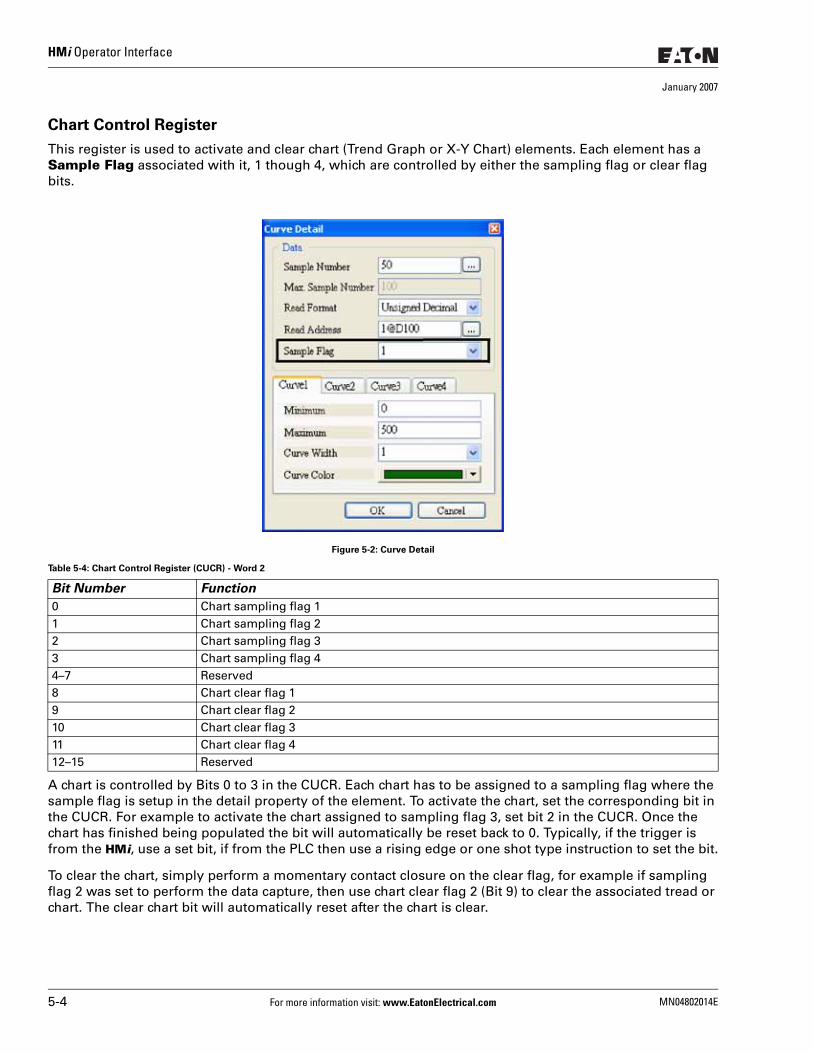
HMi Operator Interface
January 2007
Chart Control Register
This register is used to activate and clear chart (Trend Graph or X-Y Chart) elements. Each element has a Sample Flag associated with it, 1 though 4, which are controlled by either the sampling flag or clear flag bits.
Figure 5-2: Curve Detail
A chart is controlled by Bits 0 to 3 in the CUCR. Each chart has to be assigned to a sampling flag where the sample flag is setup in the detail property of the element. To activate the chart, set the corresponding bit in the CUCR. For example to activate the chart assigned to sampling flag 3, set bit 2 in the CUCR. Once the chart has finished being populated the bit will automatically be reset back to 0. Typically, if the trigger is from the HMi, use a set bit, if from the PLC then use a rising edge or one shot type instruction to set the bit.
To clear the chart, simply perform a momentary contact closure on the clear flag, for example if sampling flag 2 was set to perform the data capture, then use chart clear flag 2 (Bit 9) to clear the associated tread or chart. The clear chart bit will automatically reset after the chart is clear.
Table 5-4: Chart Control Register (CUCR) - Word 2
Bit Number Function
0 Chart sampling flag 11 Chart sampling flag 22 Chart sampling flag 33 Chart sampling flag 44–7 Reserved8 Chart clear flag 19 Chart clear flag 210 Chart clear flag 311 Chart clear flag 412–15 Reserved
5-4 For more information visit: www.EatonElectrical.com MN04802014E
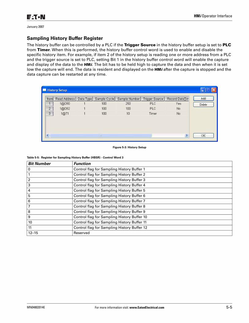
HMi Operator Interface
January 2007
Sampling History Buffer Register
The history buffer can be controlled by a PLC if the Trigger Source in the history buffer setup is set to PLC from Timer. When this is performed, the history buffer control word is used to enable and disable the specific history item. For example, if item 2 of the history setup is reading one or more address from a PLC and the trigger source is set to PLC, setting Bit 1 in the history buffer control word will enable the capture and display of the data to the HMi. The bit has to be held high to capture the data and then when it is set low the capture will end. The data is resident and displayed on the HMi after the capture is stopped and the data capture can be restarted at any time.
Figure 5-3: History Setup
Table 5-5: Register for Sampling History Buffer (HBSR) - Control Word 3
Bit Number Function
0 Control flag for Sampling History Buffer 11 Control flag for Sampling History Buffer 22 Control flag for Sampling History Buffer 33 Control flag for Sampling History Buffer 44 Control flag for Sampling History Buffer 55 Control flag for Sampling History Buffer 66 Control flag for Sampling History Buffer 77 Control flag for Sampling History Buffer 88 Control flag for Sampling History Buffer 99 Control flag for Sampling History Buffer 1010 Control flag for Sampling History Buffer 1111 Control flag for Sampling History Buffer 1212–15 Reserved
MN04802014E For more information visit: www.EatonElectrical.com 5-5
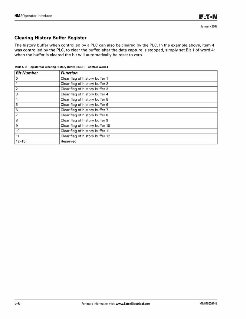
HMi Operator Interface
January 2007
Clearing History Buffer Register
The history buffer when controlled by a PLC can also be cleared by the PLC. In the example above, item 4 was controlled by the PLC, to clear the buffer, after the data capture is stopped, simply set Bit 1 of word 4; when the buffer is cleared the bit will automatically be reset to zero.
Table 5-6: Register for Clearing History Buffer (HBCR) - Control Word 4
Bit Number Function
0 Clear flag of history buffer 11 Clear flag of history buffer 22 Clear flag of history buffer 33 Clear flag of history buffer 44 Clear flag of history buffer 55 Clear flag of history buffer 66 Clear flag of history buffer 77 Clear flag of history buffer 88 Clear flag of history buffer 99 Clear flag of history buffer 1010 Clear flag of history buffer 1111 Clear flag of history buffer 1212–15 Reserved
5-6 For more information visit: www.EatonElectrical.com MN04802014E
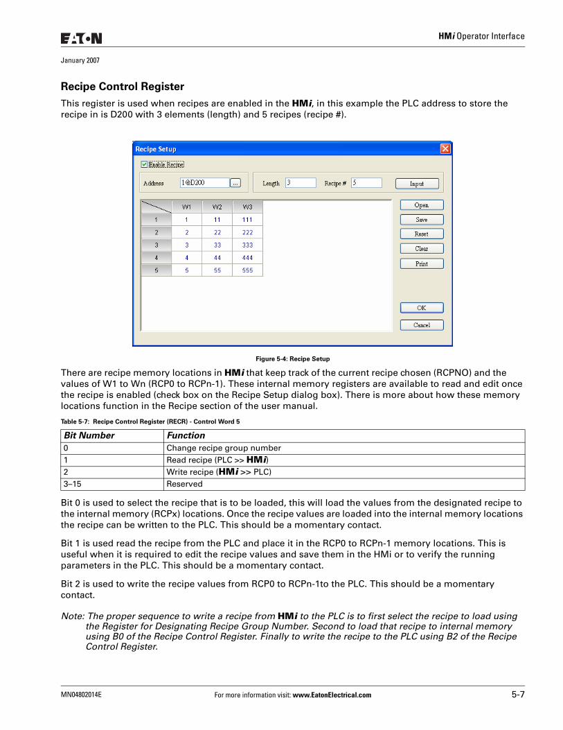
HMi Operator Interface
January 2007
Recipe Control Register
This register is used when recipes are enabled in the HMi, in this example the PLC address to store the recipe in is D200 with 3 elements (length) and 5 recipes (recipe #).
Figure 5-4: Recipe Setup
There are recipe memory locations in HMi that keep track of the current recipe chosen (RCPNO) and the values of W1 to Wn (RCP0 to RCPn-1). These internal memory registers are available to read and edit once the recipe is enabled (check box on the Recipe Setup dialog box). There is more about how these memory locations function in the Recipe section of the user manual.
Bit 0 is used to select the recipe that is to be loaded, this will load the values from the designated recipe to the internal memory (RCPx) locations. Once the recipe values are loaded into the internal memory locations the recipe can be written to the PLC. This should be a momentary contact.
Bit 1 is used read the recipe from the PLC and place it in the RCP0 to RCPn-1 memory locations. This is useful when it is required to edit the recipe values and save them in the HMi or to verify the running parameters in the PLC. This should be a momentary contact.
Bit 2 is used to write the recipe values from RCP0 to RCPn-1to the PLC. This should be a momentary contact.
Note: The proper sequence to write a recipe from HMi to the PLC is to first select the recipe to load using the Register for Designating Recipe Group Number. Second to load that recipe to internal memory using B0 of the Recipe Control Register. Finally to write the recipe to the PLC using B2 of the Recipe Control Register.
Table 5-7: Recipe Control Register (RECR) - Control Word 5
Bit Number Function
0 Change recipe group number 1 Read recipe (PLC >> HMi)2 Write recipe (HMi >> PLC)3–15 Reserved
MN04802014E For more information visit: www.EatonElectrical.com 5-7
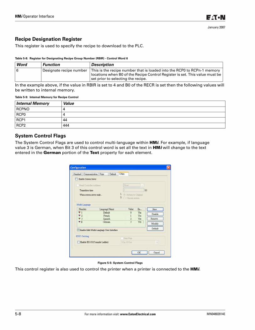
HMi Operator Interface
January 2007
Recipe Designation Register
This register is used to specify the recipe to download to the PLC.
In the example above, if the value in RBIR is set to 4 and B0 of the RECR is set then the following values will be written to internal memory.
System Control Flags
The System Control Flags are used to control multi-language within HMi. For example, if language value 3 is German, when Bit 3 of this control word is set all the text in HMi will change to the text entered in the German portion of the Text property for each element.
Figure 5-5: System Control Flags
This control register is also used to control the printer when a printer is connected to the HMi.
Table 5-8: Register for Designating Recipe Group Number (RBIR) - Control Word 6
Word Function Description
6 Designate recipe number This is the recipe number that is loaded into the RCP0 to RCPn-1 memory locations when B0 of the Recipe Control Register is set. This value must be set prior to selecting the recipe.
Table 5-9: Internal Memory for Recipe Control
Internal Memory Value
RCPNO 4RCP0 4RCP1 44RCP2 444
5-8 For more information visit: www.EatonElectrical.com MN04802014E
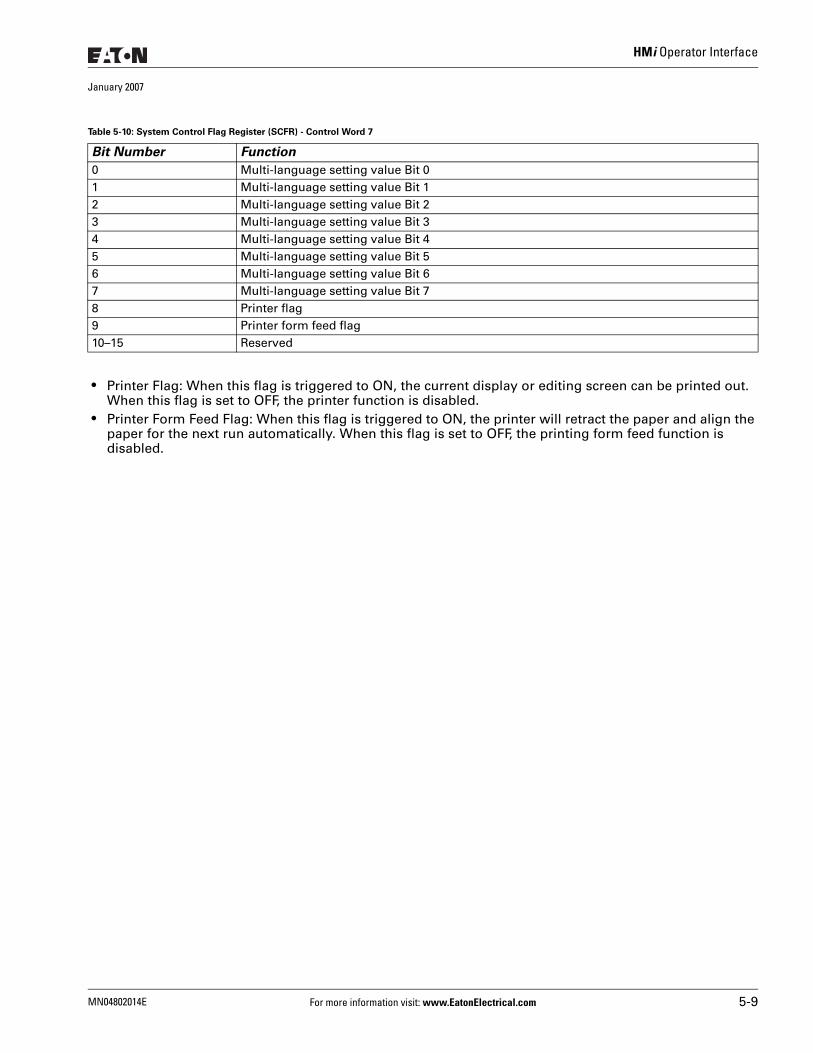
HMi Operator Interface
January 2007
● Printer Flag: When this flag is triggered to ON, the current display or editing screen can be printed out. When this flag is set to OFF, the printer function is disabled.
● Printer Form Feed Flag: When this flag is triggered to ON, the printer will retract the paper and align the paper for the next run automatically. When this flag is set to OFF, the printing form feed function is disabled.
Table 5-10: System Control Flag Register (SCFR) - Control Word 7
Bit Number Function
0 Multi-language setting value Bit 01 Multi-language setting value Bit 12 Multi-language setting value Bit 23 Multi-language setting value Bit 34 Multi-language setting value Bit 45 Multi-language setting value Bit 56 Multi-language setting value Bit 67 Multi-language setting value Bit 78 Printer flag9 Printer form feed flag10–15 Reserved
MN04802014E For more information visit: www.EatonElectrical.com 5-9
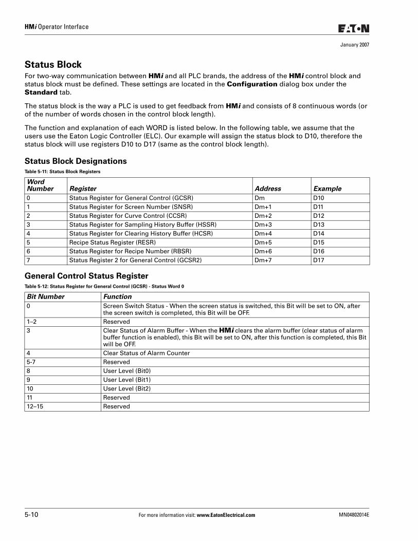
HMi Operator Interface
January 2007
Status BlockFor two-way communication between HMi and all PLC brands, the address of the HMi control block and status block must be defined. These settings are located in the Configuration dialog box under the Standard tab.
The status block is the way a PLC is used to get feedback from HMi and consists of 8 continuous words (or of the number of words chosen in the control block length).
The function and explanation of each WORD is listed below. In the following table, we assume that the users use the Eaton Logic Controller (ELC). Our example will assign the status block to D10, therefore the status block will use registers D10 to D17 (same as the control block length).
Status Block Designations
General Control Status Register
Table 5-11: Status Block Registers
Word Number Register Address Example
0 Status Register for General Control (GCSR) Dm D101 Status Register for Screen Number (SNSR) Dm+1 D112 Status Register for Curve Control (CCSR) Dm+2 D123 Status Register for Sampling History Buffer (HSSR) Dm+3 D134 Status Register for Clearing History Buffer (HCSR) Dm+4 D145 Recipe Status Register (RESR) Dm+5 D156 Status Register for Recipe Number (RBSR) Dm+6 D167 Status Register 2 for General Control (GCSR2) Dm+7 D17
Table 5-12: Status Register for General Control (GCSR) - Status Word 0
Bit Number Function
0 Screen Switch Status - When the screen status is switched, this Bit will be set to ON, after the screen switch is completed, this Bit will be OFF.
1–2 Reserved3 Clear Status of Alarm Buffer - When the HMi clears the alarm buffer (clear status of alarm
buffer function is enabled), this Bit will be set to ON, after this function is completed, this Bit will be OFF.
4 Clear Status of Alarm Counter 5-7 Reserved8 User Level (Bit0)9 User Level (Bit1)10 User Level (Bit2)11 Reserved12–15 Reserved
5-10 For more information visit: www.EatonElectrical.com MN04802014E
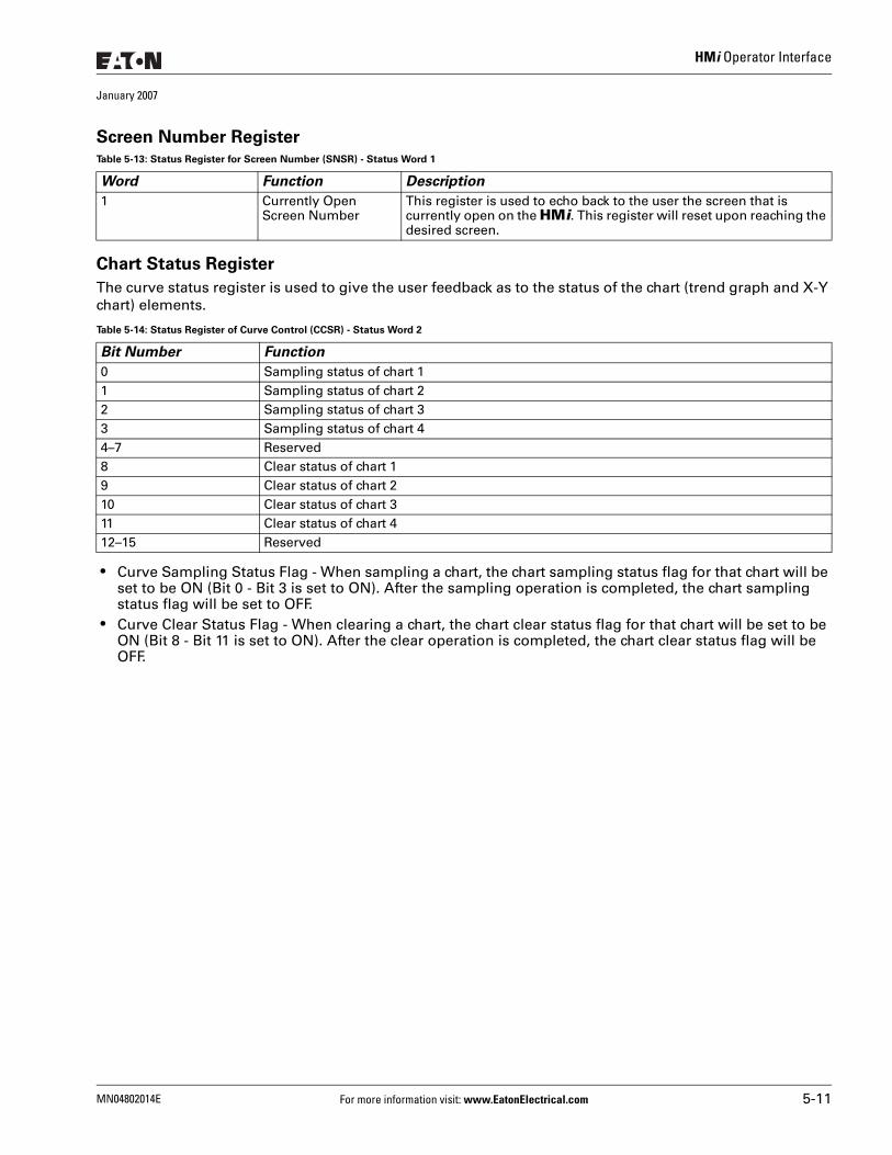
HMi Operator Interface
January 2007
Screen Number Register
Chart Status Register
The curve status register is used to give the user feedback as to the status of the chart (trend graph and X-Y chart) elements.
● Curve Sampling Status Flag - When sampling a chart, the chart sampling status flag for that chart will be set to be ON (Bit 0 - Bit 3 is set to ON). After the sampling operation is completed, the chart sampling status flag will be set to OFF.
● Curve Clear Status Flag - When clearing a chart, the chart clear status flag for that chart will be set to be ON (Bit 8 - Bit 11 is set to ON). After the clear operation is completed, the chart clear status flag will be OFF.
Table 5-13: Status Register for Screen Number (SNSR) - Status Word 1
Word Function Description
1 Currently Open Screen Number
This register is used to echo back to the user the screen that is currently open on the HMi. This register will reset upon reaching the desired screen.
Table 5-14: Status Register of Curve Control (CCSR) - Status Word 2
Bit Number Function
0 Sampling status of chart 1 1 Sampling status of chart 2 2 Sampling status of chart 33 Sampling status of chart 44–7 Reserved8 Clear status of chart 19 Clear status of chart 210 Clear status of chart 311 Clear status of chart 412–15 Reserved
MN04802014E For more information visit: www.EatonElectrical.com 5-11
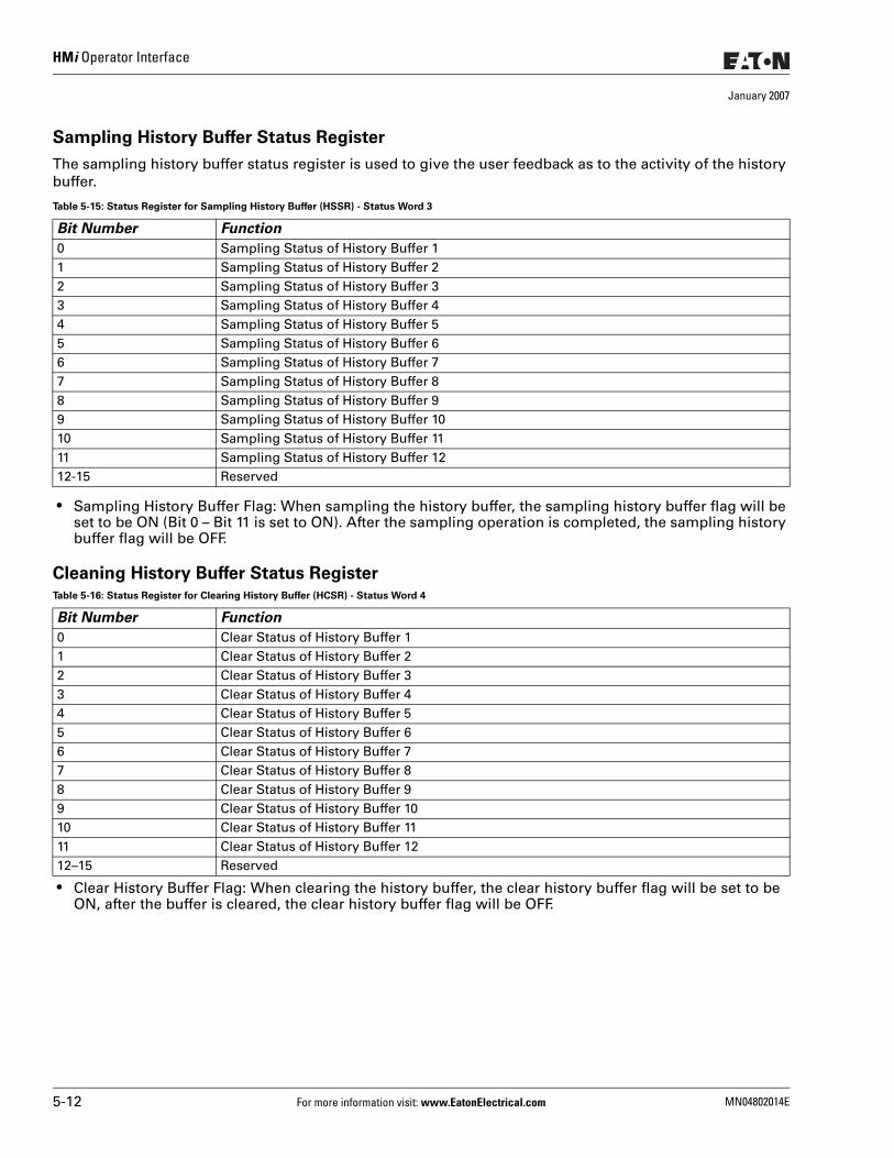
HMi Operator Interface
January 2007
Sampling History Buffer Status Register
The sampling history buffer status register is used to give the user feedback as to the activity of the history buffer.
● Sampling History Buffer Flag: When sampling the history buffer, the sampling history buffer flag will be set to be ON (Bit 0 – Bit 11 is set to ON). After the sampling operation is completed, the sampling history buffer flag will be OFF.
Cleaning History Buffer Status Register
● Clear History Buffer Flag: When clearing the history buffer, the clear history buffer flag will be set to be ON, after the buffer is cleared, the clear history buffer flag will be OFF.
Table 5-15: Status Register for Sampling History Buffer (HSSR) - Status Word 3
Bit Number Function
0 Sampling Status of History Buffer 1 1 Sampling Status of History Buffer 2 2 Sampling Status of History Buffer 33 Sampling Status of History Buffer 44 Sampling Status of History Buffer 55 Sampling Status of History Buffer 66 Sampling Status of History Buffer 77 Sampling Status of History Buffer 8 8 Sampling Status of History Buffer 99 Sampling Status of History Buffer 1010 Sampling Status of History Buffer 1111 Sampling Status of History Buffer 1212-15 Reserved
Table 5-16: Status Register for Clearing History Buffer (HCSR) - Status Word 4
Bit Number Function
0 Clear Status of History Buffer 1 1 Clear Status of History Buffer 22 Clear Status of History Buffer 33 Clear Status of History Buffer 44 Clear Status of History Buffer 55 Clear Status of History Buffer 66 Clear Status of History Buffer 77 Clear Status of History Buffer 88 Clear Status of History Buffer 99 Clear Status of History Buffer 1010 Clear Status of History Buffer 1111 Clear Status of History Buffer 1212–15 Reserved
5-12 For more information visit: www.EatonElectrical.com MN04802014E
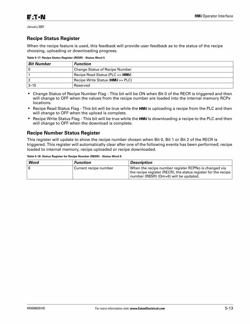
HMi Operator Interface
January 2007
Recipe Status Register
When the recipe feature is used, this feedback will provide user feedback as to the status of the recipe choosing, uploading or downloading progress.
● Change Status of Recipe Number Flag - This bit will be ON when Bit 0 of the RECR is triggered and then will change to OFF when the values from the recipe number are loaded into the internal memory RCPx locations.
● Recipe Read Status Flag - This bit will be true while the HMi is uploading a recipe from the PLC and then will change to OFF when the upload is complete.
● Recipe Write Status Flag - This bit will be true while the HMi is downloading a recipe to the PLC and then will change to OFF when the download is complete.
Recipe Number Status Register
This register will update to show the recipe number chosen when Bit 0, Bit 1 or Bit 2 of the RECR is triggered. This register will automatically clear after one of the following events has been performed; recipe loaded to internal memory, recipe uploaded or recipe downloaded.
Table 5-17: Recipe Status Register (RESR) - Status Word 5
Bit Number Function
0 Change Status of Recipe Number 1 Recipe Read Status (PLC >> HMi) 2 Recipe Write Status (HMi >> PLC) 3–15 Reserved
Table 5-18: Status Register for Recipe Number (RBSR) - Status Word 6
Word Function Description
6 Current recipe number When the recipe number register RCPNo is changed via the recipe register (RECR), the status register for the recipe number (RBSR) (Dm+6) will be updated.
MN04802014E For more information visit: www.EatonElectrical.com 5-13
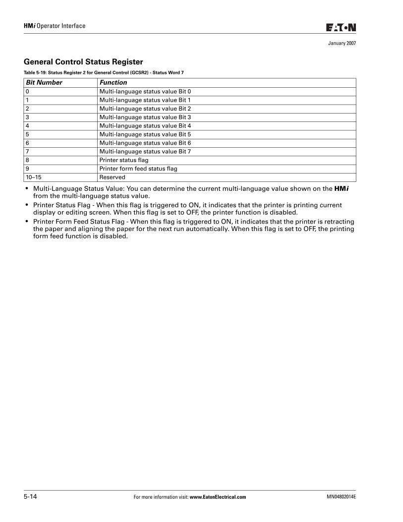
HMi Operator Interface
January 2007
General Control Status Register
● Multi-Language Status Value: You can determine the current multi-language value shown on the HMi from the multi-language status value.
● Printer Status Flag - When this flag is triggered to ON, it indicates that the printer is printing current display or editing screen. When this flag is set to OFF, the printer function is disabled.
● Printer Form Feed Status Flag - When this flag is triggered to ON, it indicates that the printer is retracting the paper and aligning the paper for the next run automatically. When this flag is set to OFF, the printing form feed function is disabled.
Table 5-19: Status Register 2 for General Control (GCSR2) - Status Word 7
Bit Number Function
0 Multi-language status value Bit 01 Multi-language status value Bit 12 Multi-language status value Bit 23 Multi-language status value Bit 34 Multi-language status value Bit 45 Multi-language status value Bit 56 Multi-language status value Bit 67 Multi-language status value Bit 78 Printer status flag9 Printer form feed status flag10–15 Reserved
5-14 For more information visit: www.EatonElectrical.com MN04802014E
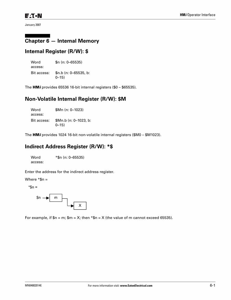
HMi Operator Interface
January 2007
Chapter 6 — Internal Memory
Internal Register (R/W): $
The HMi provides 65536 16-bit internal registers ($0 – $65535).
Non-Volatile Internal Register (R/W): $M
The HMi provides 1024 16-bit non-volatile internal registers ($M0 – $M1023).
Indirect Address Register (R/W): *$
Enter the address for the indirect address register.
Where *$n =
For example, if $n = m; $m = X; then *$n = X (the value of m cannot exceed 65535).
Word access:
$n (n: 0–65535)
Bit access: $n.b (n: 0–65535, b: 0–15)
Word access:
$Mn (n: 0–1023)
Bit access: $Mn.b (n: 0–1023, b: 0–15)
Word access:
*$n (n: 0–65535)
MN04802014E For more information visit: www.EatonElectrical.com 6-1
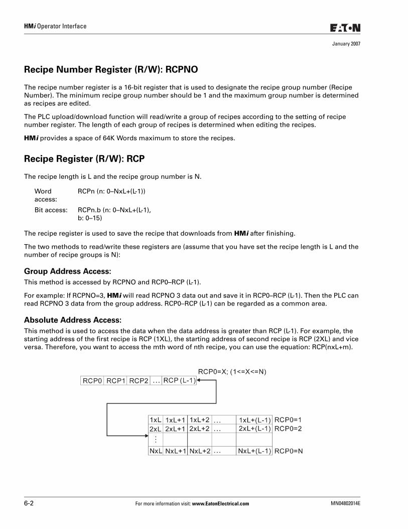
HMi Operator Interface
January 2007
Recipe Number Register (R/W): RCPNO
The recipe number register is a 16-bit register that is used to designate the recipe group number (Recipe Number). The minimum recipe group number should be 1 and the maximum group number is determined as recipes are edited.
The PLC upload/download function will read/write a group of recipes according to the setting of recipe number register. The length of each group of recipes is determined when editing the recipes.
HMi provides a space of 64K Words maximum to store the recipes.
Recipe Register (R/W): RCP
The recipe length is L and the recipe group number is N.
The recipe register is used to save the recipe that downloads from HMi after finishing.
The two methods to read/write these registers are (assume that you have set the recipe length is L and the number of recipe groups is N):
Group Address Access:
This method is accessed by RCPNO and RCP0–RCP (L-1).
For example: If RCPNO=3, HMi will read RCPNO 3 data out and save it in RCP0–RCP (L-1). Then the PLC can read RCPNO 3 data from the group address. RCP0–RCP (L-1) can be regarded as a common area.
Absolute Address Access:
This method is used to access the data when the data address is greater than RCP (L-1). For example, the starting address of the first recipe is RCP (1XL), the starting address of second recipe is RCP (2XL) and vice versa. Therefore, you want to access the mth word of nth recipe, you can use the equation: RCP(nxL+m).
Word access:
RCPn (n: 0–NxL+(L-1))
Bit access: RCPn.b (n: 0–NxL+(L-1), b: 0–15)
6-2 For more information visit: www.EatonElectrical.com MN04802014E
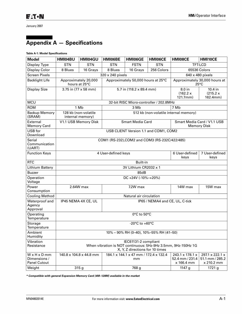
HMi Operator Interface
January 2007
Appendix A — Specifications
* Compatible with general Expansion Memory Card (4M–128M) available in the market
Table A-1: Model Specifications
Model HMI04BU HMI04GU HMI06BE HMI06GE HMI06CE HMI08CE HMI10CE
Display Type STN STN STN FSTN STN TFT-LCDDisplay Color 8 Blues 16 Grays 8 Blues 16 Grays 256 Colors 65536 Colors Screen Pixels 320 x 240 pixels 640 x 480 pixelsBacklight Life Approximately 20,000
hours at 25°CApproximately 50,000 hours at 25°C Approximately 30,000 hours at
25°CDisplay Size 3.75 in (77 x 58 mm) 5.7 in (118.2 x 89.4 mm) 8.0 in
(162.2 x 121.7mm)
10.4 in (215.2 x
162.4mm)MCU 32-bit RISC Micro-controller / 202.8MHzROM 1 Mb 3 Mb 7 MbBackup Memory(SRAM)
128 kb (non-volatile internal memory)
512 kb (non-volatile internal memory)
External Memory Card
V1.1 USB Memory Disk Smart Media Card Smart Media Card / V1.1 USB Memory Disk
USB for Download
USB CLIENT Version 1.1 and COM1, COM2
Serial Communication (UART)
COM1 (RS-232),COM2 and COM3 (RS-232C/422/485)
Function Keys 4 User-defined keys 6 User-defined keys
7 User-defined keys
RTC Built-inLithium Battery 3V Lithium CR2032 x 1Buzzer 85dBOperation Voltage
DC +24V (-10%–+20%)
Power Consumption
2.64W max 7.2W max 14W max 15W max
Cooling Method Natural air circulationWaterproof and Agency Approval
IP45 NEMA 4X CE, UL IP65 / NEMA4 and CE, UL, C-tick
Operating Temperature
0°C to 50°C
Storage Temperature
-20°C to +60°C
Ambient Humidity
10% – 90% RH (0–40), 10%–55% RH (41–50)
Vibration Resistance
IEC61131-2 compliantWhen vibration is NOT continuous: 5Hz-9Hz 3.5mm, 9Hz-150Hz 1G
X, Y, Z directions for 10 times W x H x D mmDimensions / Panel Cutout
140.8 x 104.8 x 44.8 mm 184.1 x 144.1 x 47 mm / 172.4 x 132.4 mm
243.1 x 178.1 x 52.4 mm / 231.4
x 166.4 mm
297.1 x 222.1 x 51.1 mm / 285.2
x 210.2 mm Weight 315 g 768 g 1147 g 1721 g
MN04802014E For more information visit: www.EatonElectrical.com A-1
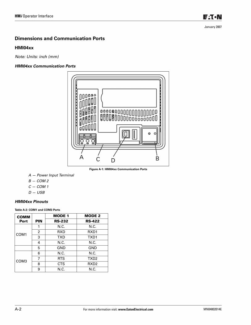
HMi Operator Interface
January 2007
Dimensions and Communication Ports
HMI04xx
Note: Units: inch (mm)
HMI04xx Communication Ports
Figure A-1: HMI04xx Communication Ports
A — Power Input Terminal
B — COM 2
C — COM 1
D — USB
HMI04xx Pinouts
Table A-2: COM1 and COM3 Ports
COMM Port PIN
MODE 1 MODE 2RS-232 RS-422
COM1
1 N.C. N.C.2 RXD RXD13 TXD TXD14 N.C. N.C.5 GND GND
COM3
6 N.C. N.C.7 RTS TXD28 CTS RXD29 N.C. N.C.
A-2 For more information visit: www.EatonElectrical.com MN04802014E
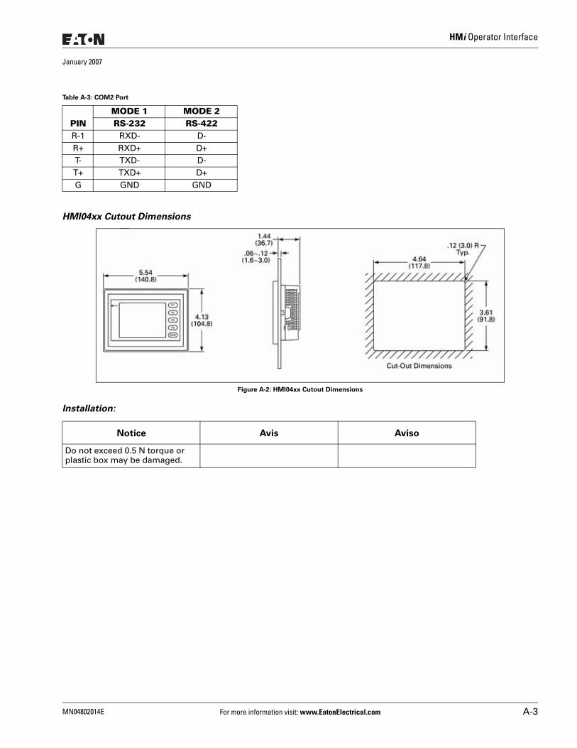
HMi Operator Interface
January 2007
HMI04xx Cutout Dimensions
Figure A-2: HMI04xx Cutout Dimensions
Installation:
Table A-3: COM2 Port
PINMODE 1 MODE 2RS-232 RS-422
R-1 RXD- D-R+ RXD+ D+T- TXD- D-T+ TXD+ D+G GND GND
Do not exceed 0.5 N torque or plastic box may be damaged.
Notice Avis Aviso
MN04802014E For more information visit: www.EatonElectrical.com A-3
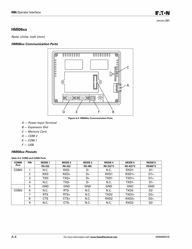
HMi Operator Interface
January 2007
HMI06xx
Note: Units: inch (mm)
HMI06xx Communication Ports
Figure A-3: HMI06xx Communication Ports
A — Power Input Terminal
B — Expansion Slot
C — Memory Card
D — COM 2
E — COM 1
F — USB
HMI06xx Pinouts
Table A-4: COM2 and COM3 Ports
COMM Port
PIN MODE 1 MODE 2 MODE 3 MODE 4 MODE 5 MODE 6
RS-232 RS-422 RS-485 RS-232*2 RS-422*2 RS485*2
COM2 1 N.C. RXD- D- N.C. RXD1- D1-2 RXD RXD+ D+ RXD1 RXD1+ D1+3 TXD TXD+ D+ TXD1 TXD1+ D1+4 N.C. TXD- D- N.C. TXD1- D1-5 GND GND GND GND GND GND
COM3 6 N.C. RTS- N.C. N.C. TXD2- D2-7 RTS RTS+ N.C. TXD2 TXD2+ D2+8 CTS CTS+ N.C. RXD2 RXD2+ D2+9 N.C. CTS- N.C. N.C. RXD2- D2-
A-4 For more information visit: www.EatonElectrical.com MN04802014E
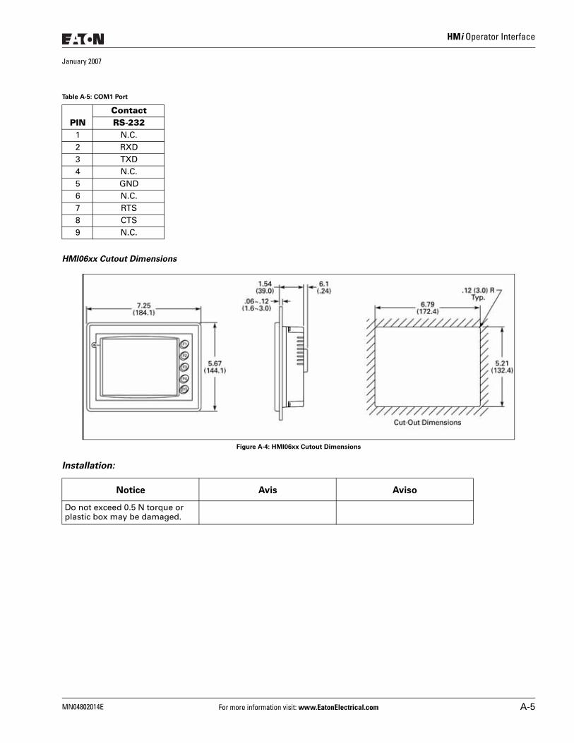
HMi Operator Interface
January 2007
HMI06xx Cutout Dimensions
Figure A-4: HMI06xx Cutout Dimensions
Installation:
Table A-5: COM1 Port
PINContactRS-232
1 N.C.2 RXD3 TXD4 N.C.5 GND6 N.C.7 RTS8 CTS9 N.C.
Do not exceed 0.5 N torque or plastic box may be damaged.
Notice Avis Aviso
MN04802014E For more information visit: www.EatonElectrical.com A-5
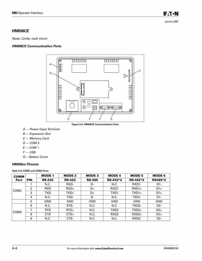
HMi Operator Interface
January 2007
HMI08CE
Note: Units: inch (mm)
HMI08CE Communication Ports
Figure A-5: HMI08CE Communication Ports
A — Power Input Terminal
B — Expansion Slot
C — Memory Card
D — COM 2
E — COM 1
F — USB
G— Battery Cover
HMI08xx Pinouts
Table A-6: COM2 and COM3 Ports
COMM Port PIN
MODE 1 MODE 2 MODE 3 MODE 4 MODE 5 MODE 6RS-232 RS-422 RS-485 RS-232*2 RS-422*2 RS485*2
COM2
1 N.C. RXD- D- N.C. RXD1- D1-2 RXD RXD+ D+ RXD1 RXD1+ D1+3 TXD TXD+ D+ TXD1 TXD1+ D1+4 N.C. TXD- D- N.C. TXD1- D1-5 GND GND GND GND GND GND
COM3
6 N.C. RTS- N.C. N.C. TXD2- D2-7 RTS RTS+ N.C. TXD2 TXD2+ D2+8 CTS CTS+ N.C. RXD2 RXD2+ D2+9 N.C. CTS- N.C. N.C. RXD2- D2-
A-6 For more information visit: www.EatonElectrical.com MN04802014E
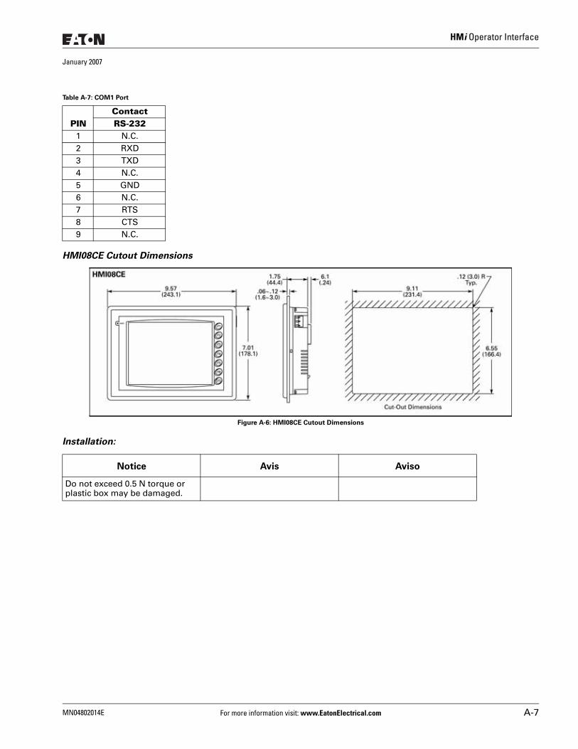
HMi Operator Interface
January 2007
HMI08CE Cutout Dimensions
Figure A-6: HMI08CE Cutout Dimensions
Installation:
Table A-7: COM1 Port
PINContactRS-232
1 N.C.2 RXD3 TXD4 N.C.5 GND6 N.C.7 RTS8 CTS9 N.C.
Do not exceed 0.5 N torque or plastic box may be damaged.
Notice Avis Aviso
MN04802014E For more information visit: www.EatonElectrical.com A-7
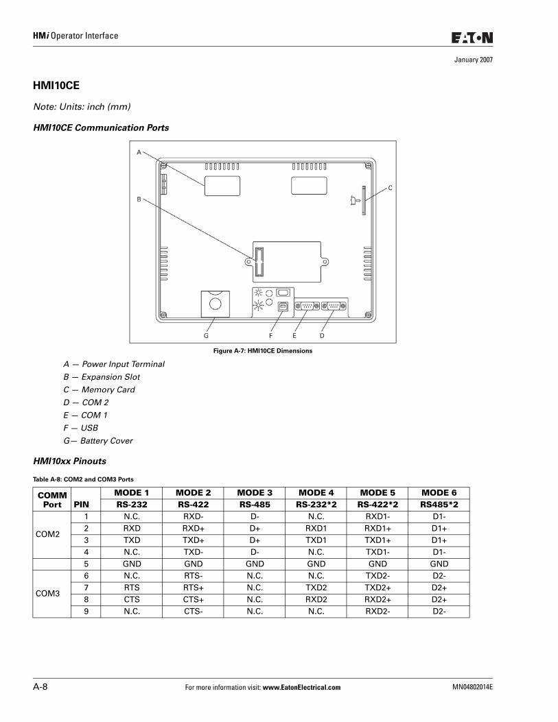
HMi Operator Interface
January 2007
HMI10CE
Note: Units: inch (mm)
HMI10CE Communication Ports
Figure A-7: HMI10CE Dimensions
A — Power Input Terminal
B — Expansion Slot
C — Memory Card
D — COM 2
E — COM 1
F — USB
G— Battery Cover
HMI10xx Pinouts
Table A-8: COM2 and COM3 Ports
COMM Port PIN
MODE 1 MODE 2 MODE 3 MODE 4 MODE 5 MODE 6RS-232 RS-422 RS-485 RS-232*2 RS-422*2 RS485*2
COM2
1 N.C. RXD- D- N.C. RXD1- D1-2 RXD RXD+ D+ RXD1 RXD1+ D1+3 TXD TXD+ D+ TXD1 TXD1+ D1+4 N.C. TXD- D- N.C. TXD1- D1-5 GND GND GND GND GND GND
COM3
6 N.C. RTS- N.C. N.C. TXD2- D2-7 RTS RTS+ N.C. TXD2 TXD2+ D2+8 CTS CTS+ N.C. RXD2 RXD2+ D2+9 N.C. CTS- N.C. N.C. RXD2- D2-
A-8 For more information visit: www.EatonElectrical.com MN04802014E
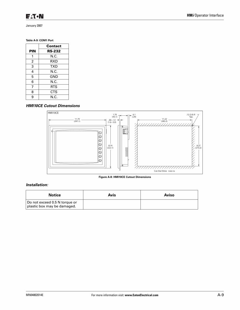
HMi Operator Interface
January 2007
HMI10CE Cutout Dimensions
Figure A-8: HMI10CE Cutout Dimensions
Installation:
Table A-9: COM1 Port
PINContactRS-232
1 N.C.2 RXD3 TXD4 N.C.5 GND6 N.C.7 RTS8 CTS9 N.C.
Do not exceed 0.5 N torque or plastic box may be damaged.
11.70(297.1)
F1
1.70(43.1)
.06~.12(1.6~3.0)
8.74(222.1)
6.1(.24)
.12 (3.0) RTyp.
8.27(210.2)
11.22(285.2)
Cut-Out Dime nsio ns
F2
F3
F4
F5
F6
F7
S Y S
POWER
HMI10CE
Notice Avis Aviso
MN04802014E For more information visit: www.EatonElectrical.com A-9

HMi Operator Interface
January 2007
A-10 For more information visit: www.EatonElectrical.com MN04802014E
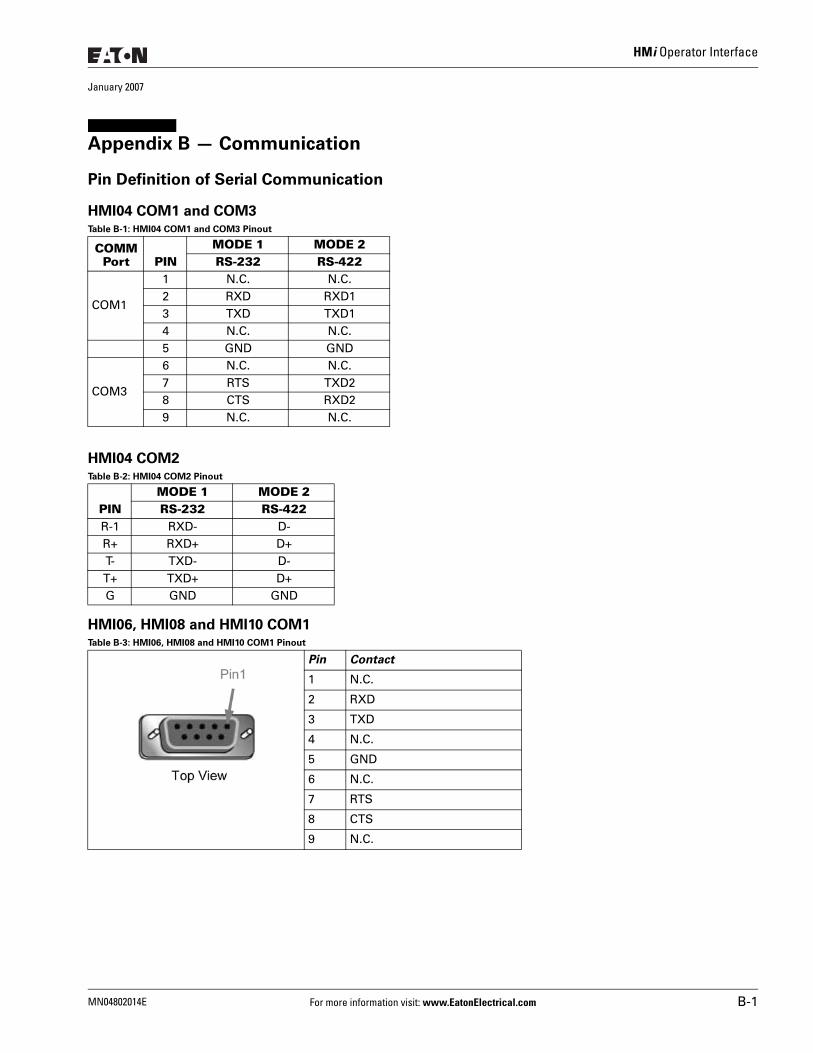
HMi Operator Interface
January 2007
Appendix B — Communication
Pin Definition of Serial Communication
HMI04 COM1 and COM3Table B-1: HMI04 COM1 and COM3 Pinout
HMI04 COM2Table B-2: HMI04 COM2 Pinout
HMI06, HMI08 and HMI10 COM1Table B-3: HMI06, HMI08 and HMI10 COM1 Pinout
COMM Port PIN
MODE 1 MODE 2RS-232 RS-422
COM1
1 N.C. N.C.2 RXD RXD13 TXD TXD14 N.C. N.C.5 GND GND
COM3
6 N.C. N.C.7 RTS TXD28 CTS RXD29 N.C. N.C.
PINMODE 1 MODE 2RS-232 RS-422
R-1 RXD- D-R+ RXD+ D+T- TXD- D-T+ TXD+ D+G GND GND
Pin Contact
1 N.C.
2 RXD
3 TXD
4 N.C.
5 GND
6 N.C.
7 RTS
8 CTS
9 N.C.
MN04802014E For more information visit: www.EatonElectrical.com B-1
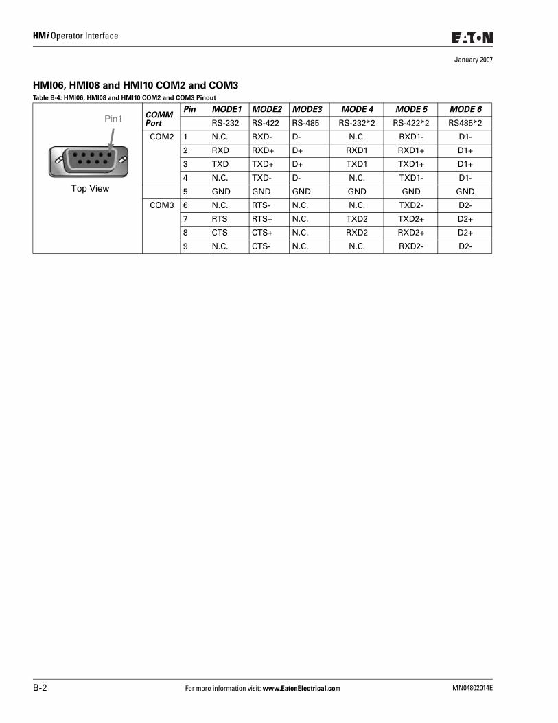
HMi Operator Interface
January 2007
HMI06, HMI08 and HMI10 COM2 and COM3Table B-4: HMI06, HMI08 and HMI10 COM2 and COM3 Pinout
COMM Port
Pin MODE1 MODE2 MODE3 MODE 4 MODE 5 MODE 6
RS-232 RS-422 RS-485 RS-232*2 RS-422*2 RS485*2
COM2 1 N.C. RXD- D- N.C. RXD1- D1-
2 RXD RXD+ D+ RXD1 RXD1+ D1+
3 TXD TXD+ D+ TXD1 TXD1+ D1+
4 N.C. TXD- D- N.C. TXD1- D1-
5 GND GND GND GND GND GND
COM3 6 N.C. RTS- N.C. N.C. TXD2- D2-
7 RTS RTS+ N.C. TXD2 TXD2+ D2+
8 CTS CTS+ N.C. RXD2 RXD2+ D2+
9 N.C. CTS- N.C. N.C. RXD2- D2-
B-2 For more information visit: www.EatonElectrical.com MN04802014E
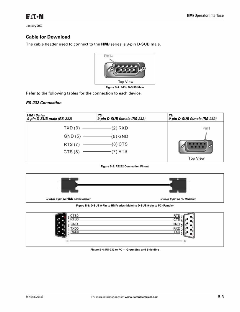
HMi Operator Interface
January 2007
Cable for Download
The cable header used to connect to the HMi series is 9-pin D-SUB male.
Figure B-1: 9-Pin D-SUB Male
Refer to the following tables for the connection to each device.
RS-232 Connection
Figure B-2: RS232 Connection Pinout
Figure B-3: D-SUB 9-Pin to HMi series (Male) to D-SUB 9-pin to PC (Female)
Figure B-4: RS-232 to PC — Grounding and Shielding
HMi Series9-pin D-SUB male (RS-232)
PC 9-pin D-SUB female (RS-232)
PC 9-pin D-SUB female (RS-232)
D-SUB 9-pin to HMi series (male) D-SUB 9-pin to PC (female)
MN04802014E For more information visit: www.EatonElectrical.com B-3
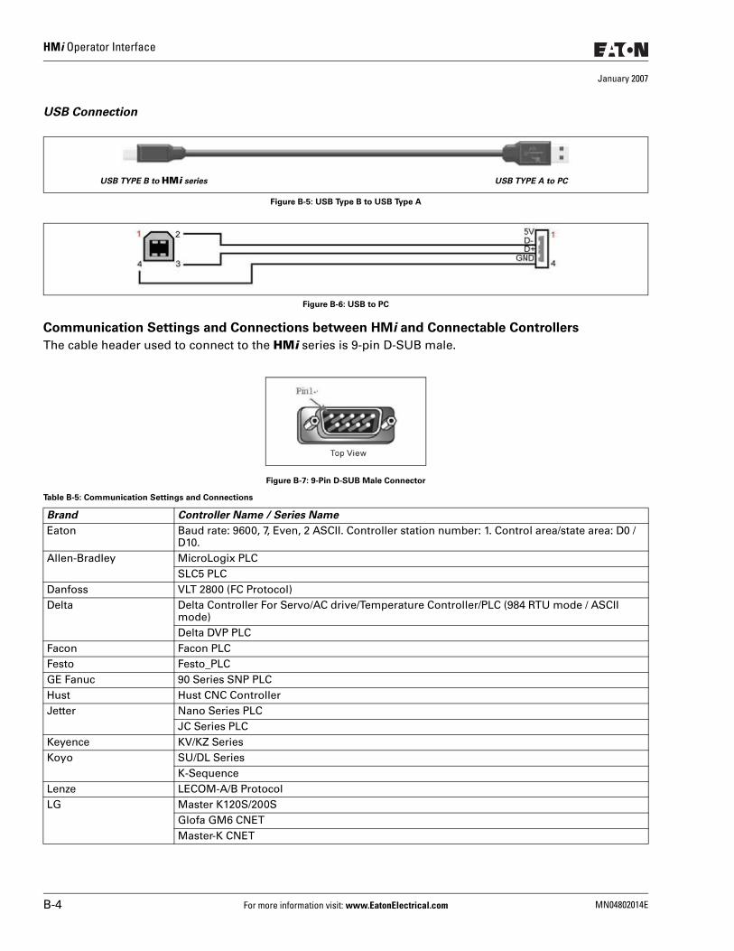
HMi Operator Interface
January 2007
USB Connection
Figure B-5: USB Type B to USB Type A
Figure B-6: USB to PC
Communication Settings and Connections between HMi and Connectable Controllers
The cable header used to connect to the HMi series is 9-pin D-SUB male.
Figure B-7: 9-Pin D-SUB Male Connector
Table B-5: Communication Settings and Connections
Brand Controller Name / Series Name
Eaton Baud rate: 9600, 7, Even, 2 ASCII. Controller station number: 1. Control area/state area: D0 / D10.
Allen-Bradley MicroLogix PLCSLC5 PLC
Danfoss VLT 2800 (FC Protocol)Delta Delta Controller For Servo/AC drive/Temperature Controller/PLC (984 RTU mode / ASCII
mode)Delta DVP PLC
Facon Facon PLCFesto Festo_PLCGE Fanuc 90 Series SNP PLCHust Hust CNC ControllerJetter Nano Series PLC
JC Series PLCKeyence KV/KZ SeriesKoyo SU/DL Series
K-SequenceLenze LECOM-A/B ProtocolLG Master K120S/200S
Glofa GM6 CNETMaster-K CNET
USB TYPE B to HMi series USB TYPE A to PC
B-4 For more information visit: www.EatonElectrical.com MN04802014E
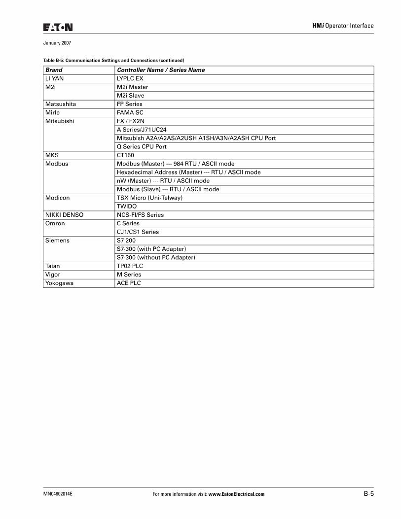
HMi Operator Interface
January 2007
LI YAN LYPLC EXM2i M2i Master
M2i SlaveMatsushita FP SeriesMirle FAMA SCMitsubishi FX / FX2N
A Series/J71UC24Mitsubish A2A/A2AS/A2USH A1SH/A3N/A2ASH CPU PortQ Series CPU Port
MKS CT150Modbus Modbus (Master) --- 984 RTU / ASCII mode
Hexadecimal Address (Master) --- RTU / ASCII modenW (Master) --- RTU / ASCII modeModbus (Slave) --- RTU / ASCII mode
Modicon TSX Micro (Uni-Telway)TWIDO
NIKKI DENSO NCS-FI/FS SeriesOmron C Series
CJ1/CS1 SeriesSiemens S7 200
S7-300 (with PC Adapter)S7-300 (without PC Adapter)
Taian TP02 PLCVigor M SeriesYokogawa ACE PLC
Table B-5: Communication Settings and Connections (continued)
Brand Controller Name / Series Name
MN04802014E For more information visit: www.EatonElectrical.com B-5
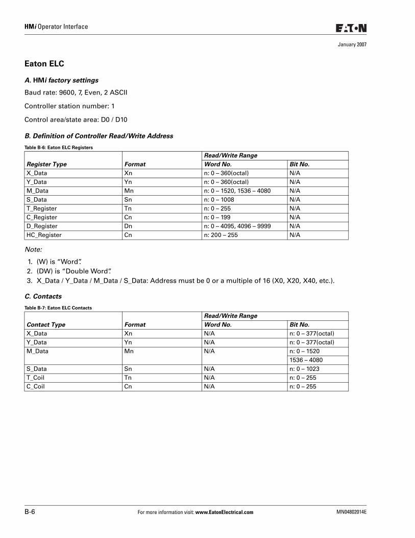
HMi Operator Interface
January 2007
Eaton ELC
A. HMi factory settings
Baud rate: 9600, 7, Even, 2 ASCII
Controller station number: 1
Control area/state area: D0 / D10
B. Definition of Controller Read/Write Address
Table B-6: Eaton ELC Registers
Note:
1. (W) is “Word”.2. (DW) is “Double Word”.3. X_Data / Y_Data / M_Data / S_Data: Address must be 0 or a multiple of 16 (X0, X20, X40, etc.).
C. Contacts
Table B-7: Eaton ELC Contacts
Register Type Format
Read/Write Range
Word No. Bit No.
X_Data Xn n: 0 – 360(octal) N/AY_Data Yn n: 0 – 360(octal) N/AM_Data Mn n: 0 – 1520, 1536 – 4080 N/AS_Data Sn n: 0 – 1008 N/AT_Register Tn n: 0 – 255 N/AC_Register Cn n: 0 – 199 N/AD_Register Dn n: 0 – 4095, 4096 – 9999 N/AHC_Register Cn n: 200 – 255 N/A
Contact Type Format
Read/Write Range
Word No. Bit No.
X_Data Xn N/A n: 0 – 377(octal)Y_Data Yn N/A n: 0 – 377(octal)M_Data Mn N/A n: 0 – 1520
1536 – 4080S_Data Sn N/A n: 0 – 1023T_Coil Tn N/A n: 0 – 255C_Coil Cn N/A n: 0 – 255
B-6 For more information visit: www.EatonElectrical.com MN04802014E
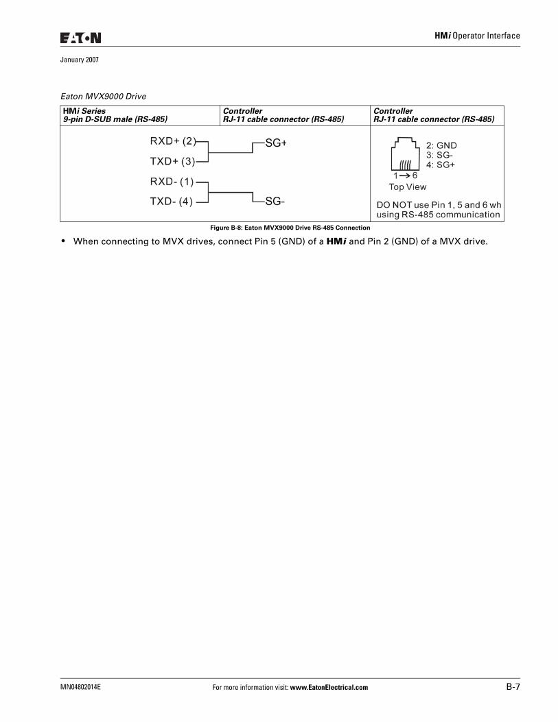
HMi Operator Interface
January 2007
Figure B-8: Eaton MVX9000 Drive RS-485 Connection
● When connecting to MVX drives, connect Pin 5 (GND) of a HMi and Pin 2 (GND) of a MVX drive.
Eaton MVX9000 Drive
HMi Series9-pin D-SUB male (RS-485)
ControllerRJ-11 cable connector (RS-485)
ControllerRJ-11 cable connector (RS-485)
MN04802014E For more information visit: www.EatonElectrical.com B-7
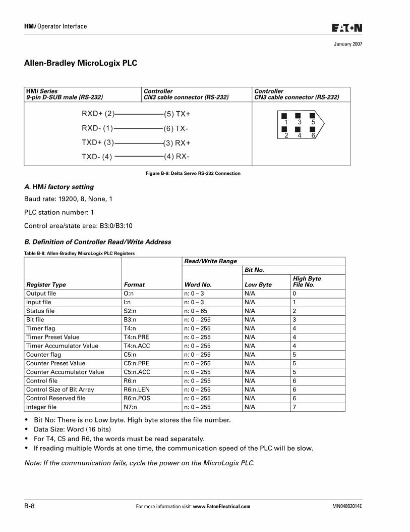
HMi Operator Interface
January 2007
Allen-Bradley MicroLogix PLC
Figure B-9: Delta Servo RS-232 Connection
A. HMi factory setting
Baud rate: 19200, 8, None, 1
PLC station number: 1
Control area/state area: B3:0/B3:10
B. Definition of Controller Read/Write Address
Table B-8: Allen-Bradley MicroLogix PLC Registers
● Bit No: There is no Low byte. High byte stores the file number. ● Data Size: Word (16 bits) ● For T4, C5 and R6, the words must be read separately. ● If reading multiple Words at one time, the communication speed of the PLC will be slow.
Note: If the communication fails, cycle the power on the MicroLogix PLC.
HMi Series9-pin D-SUB male (RS-232)
ControllerCN3 cable connector (RS-232)
ControllerCN3 cable connector (RS-232)
Register Type Format
Read/Write Range
Word No.
Bit No.
Low ByteHigh ByteFile No.
Output file O:n n: 0 – 3 N/A 0Input file I:n n: 0 – 3 N/A 1Status file S2:n n: 0 – 65 N/A 2Bit file B3:n n: 0 – 255 N/A 3Timer flag T4:n n: 0 – 255 N/A 4Timer Preset Value T4:n.PRE n: 0 – 255 N/A 4Timer Accumulator Value T4:n.ACC n: 0 – 255 N/A 4Counter flag C5:n n: 0 – 255 N/A 5Counter Preset Value C5:n.PRE n: 0 – 255 N/A 5Counter Accumulator Value C5:n.ACC n: 0 – 255 N/A 5Control file R6:n n: 0 – 255 N/A 6Control Size of Bit Array R6:n.LEN n: 0 – 255 N/A 6Control Reserved file R6:n.POS n: 0 – 255 N/A 6Integer file N7:n n: 0 – 255 N/A 7
B-8 For more information visit: www.EatonElectrical.com MN04802014E
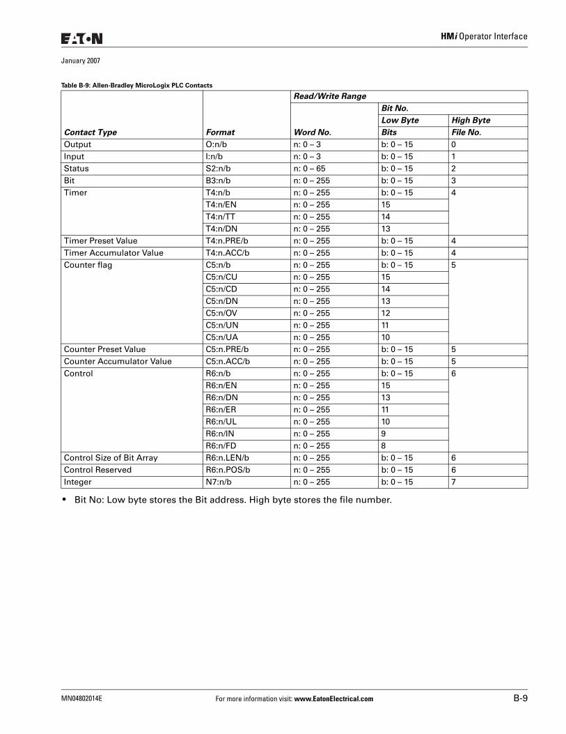
HMi Operator Interface
January 2007
Table B-9: Allen-Bradley MicroLogix PLC Contacts
● Bit No: Low byte stores the Bit address. High byte stores the file number.
Contact Type Format
Read/Write Range
Word No.
Bit No.
Low Byte High Byte
Bits File No.
Output O:n/b n: 0 – 3 b: 0 – 15 0Input I:n/b n: 0 – 3 b: 0 – 15 1Status S2:n/b n: 0 – 65 b: 0 – 15 2Bit B3:n/b n: 0 – 255 b: 0 – 15 3Timer T4:n/b n: 0 – 255 b: 0 – 15 4
T4:n/EN n: 0 – 255 15T4:n/TT n: 0 – 255 14T4:n/DN n: 0 – 255 13
Timer Preset Value T4:n.PRE/b n: 0 – 255 b: 0 – 15 4Timer Accumulator Value T4:n.ACC/b n: 0 – 255 b: 0 – 15 4Counter flag C5:n/b n: 0 – 255 b: 0 – 15 5
C5:n/CU n: 0 – 255 15C5:n/CD n: 0 – 255 14C5:n/DN n: 0 – 255 13C5:n/OV n: 0 – 255 12C5:n/UN n: 0 – 255 11C5:n/UA n: 0 – 255 10
Counter Preset Value C5:n.PRE/b n: 0 – 255 b: 0 – 15 5Counter Accumulator Value C5:n.ACC/b n: 0 – 255 b: 0 – 15 5Control R6:n/b n: 0 – 255 b: 0 – 15 6
R6:n/EN n: 0 – 255 15R6:n/DN n: 0 – 255 13R6:n/ER n: 0 – 255 11R6:n/UL n: 0 – 255 10R6:n/IN n: 0 – 255 9R6:n/FD n: 0 – 255 8
Control Size of Bit Array R6:n.LEN/b n: 0 – 255 b: 0 – 15 6Control Reserved R6:n.POS/b n: 0 – 255 b: 0 – 15 6Integer N7:n/b n: 0 – 255 b: 0 – 15 7
MN04802014E For more information visit: www.EatonElectrical.com B-9
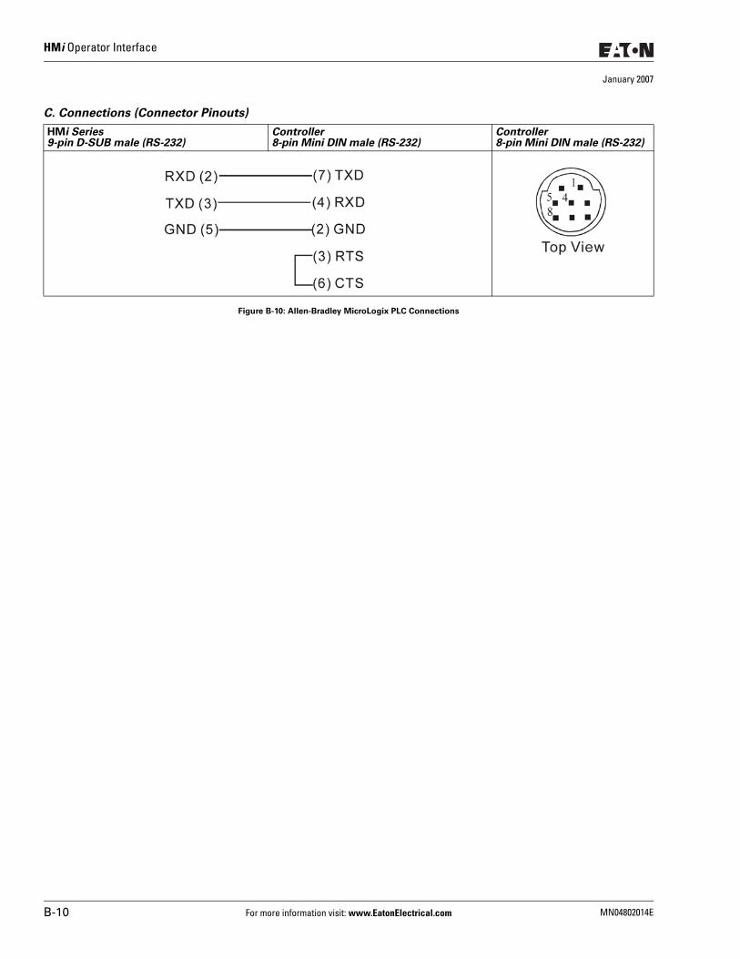
HMi Operator Interface
January 2007
C. Connections (Connector Pinouts)
Figure B-10: Allen-Bradley MicroLogix PLC Connections
HMi Series9-pin D-SUB male (RS-232)
Controller8-pin Mini DIN male (RS-232)
Controller8-pin Mini DIN male (RS-232)
B-10 For more information visit: www.EatonElectrical.com MN04802014E
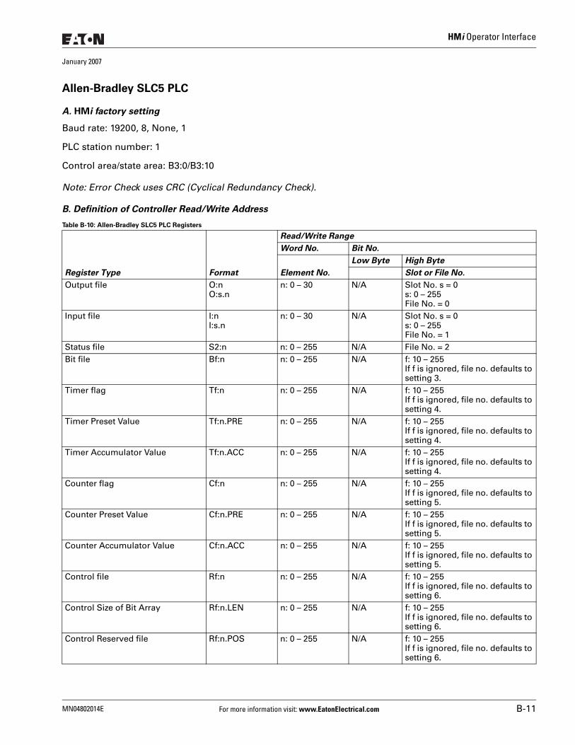
HMi Operator Interface
January 2007
Allen-Bradley SLC5 PLC
A. HMi factory setting
Baud rate: 19200, 8, None, 1
PLC station number: 1
Control area/state area: B3:0/B3:10
Note: Error Check uses CRC (Cyclical Redundancy Check).
B. Definition of Controller Read/Write Address
Table B-10: Allen-Bradley SLC5 PLC Registers
Register Type Format
Read/Write Range
Word No. Bit No.
Element No.
Low Byte High Byte
Slot or File No.
Output file O:nO:s.n
n: 0 – 30 N/A Slot No. s = 0s: 0 – 255File No. = 0
Input file I:nI:s.n
n: 0 – 30 N/A Slot No. s = 0s: 0 – 255File No. = 1
Status file S2:n n: 0 – 255 N/A File No. = 2Bit file Bf:n n: 0 – 255 N/A f: 10 – 255
If f is ignored, file no. defaults to setting 3.
Timer flag Tf:n n: 0 – 255 N/A f: 10 – 255If f is ignored, file no. defaults to setting 4.
Timer Preset Value Tf:n.PRE n: 0 – 255 N/A f: 10 – 255If f is ignored, file no. defaults to setting 4.
Timer Accumulator Value Tf:n.ACC n: 0 – 255 N/A f: 10 – 255If f is ignored, file no. defaults to setting 4.
Counter flag Cf:n n: 0 – 255 N/A f: 10 – 255If f is ignored, file no. defaults to setting 5.
Counter Preset Value Cf:n.PRE n: 0 – 255 N/A f: 10 – 255If f is ignored, file no. defaults to setting 5.
Counter Accumulator Value Cf:n.ACC n: 0 – 255 N/A f: 10 – 255If f is ignored, file no. defaults to setting 5.
Control file Rf:n n: 0 – 255 N/A f: 10 – 255If f is ignored, file no. defaults to setting 6.
Control Size of Bit Array Rf:n.LEN n: 0 – 255 N/A f: 10 – 255If f is ignored, file no. defaults to setting 6.
Control Reserved file Rf:n.POS n: 0 – 255 N/A f: 10 – 255If f is ignored, file no. defaults to setting 6.
MN04802014E For more information visit: www.EatonElectrical.com B-11
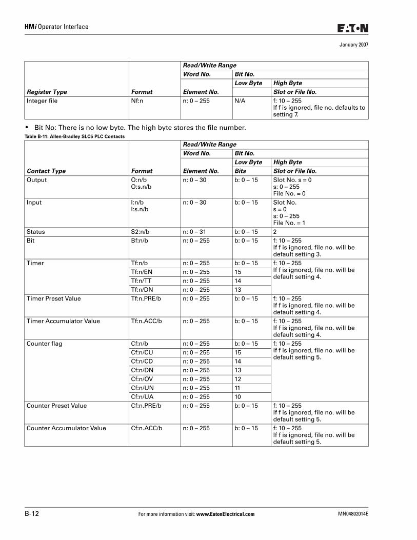
HMi Operator Interface
January 2007
● Bit No: There is no low byte. The high byte stores the file number.Table B-11: Allen-Bradley SLC5 PLC Contacts
Integer file Nf:n n: 0 – 255 N/A f: 10 – 255If f is ignored, file no. defaults to setting 7.
Contact Type Format
Read/Write Range
Word No. Bit No.
Element No.
Low Byte High Byte
Bits Slot or File No.
Output O:n/bO:s.n/b
n: 0 – 30 b: 0 – 15 Slot No. s = 0s: 0 – 255File No. = 0
Input I:n/bI:s.n/b
n: 0 – 30 b: 0 – 15 Slot No.s = 0s: 0 – 255File No. = 1
Status S2:n/b n: 0 – 31 b: 0 – 15 2Bit Bf:n/b n: 0 – 255 b: 0 – 15 f: 10 – 255
If f is ignored, file no. will be default setting 3.
Timer Tf:n/b n: 0 – 255 b: 0 – 15 f: 10 – 255If f is ignored, file no. will be default setting 4.
Tf:n/EN n: 0 – 255 15Tf:n/TT n: 0 – 255 14Tf:n/DN n: 0 – 255 13
Timer Preset Value Tf:n.PRE/b n: 0 – 255 b: 0 – 15 f: 10 – 255If f is ignored, file no. will be default setting 4.
Timer Accumulator Value Tf:n.ACC/b n: 0 – 255 b: 0 – 15 f: 10 – 255If f is ignored, file no. will be default setting 4.
Counter flag Cf:n/b n: 0 – 255 b: 0 – 15 f: 10 – 255If f is ignored, file no. will be default setting 5.
Cf:n/CU n: 0 – 255 15Cf:n/CD n: 0 – 255 14Cf:n/DN n: 0 – 255 13Cf:n/OV n: 0 – 255 12Cf:n/UN n: 0 – 255 11Cf:n/UA n: 0 – 255 10
Counter Preset Value Cf:n.PRE/b n: 0 – 255 b: 0 – 15 f: 10 – 255If f is ignored, file no. will be default setting 5.
Counter Accumulator Value Cf:n.ACC/b n: 0 – 255 b: 0 – 15 f: 10 – 255If f is ignored, file no. will be default setting 5.
Register Type Format
Read/Write Range
Word No. Bit No.
Element No.
Low Byte High Byte
Slot or File No.
B-12 For more information visit: www.EatonElectrical.com MN04802014E
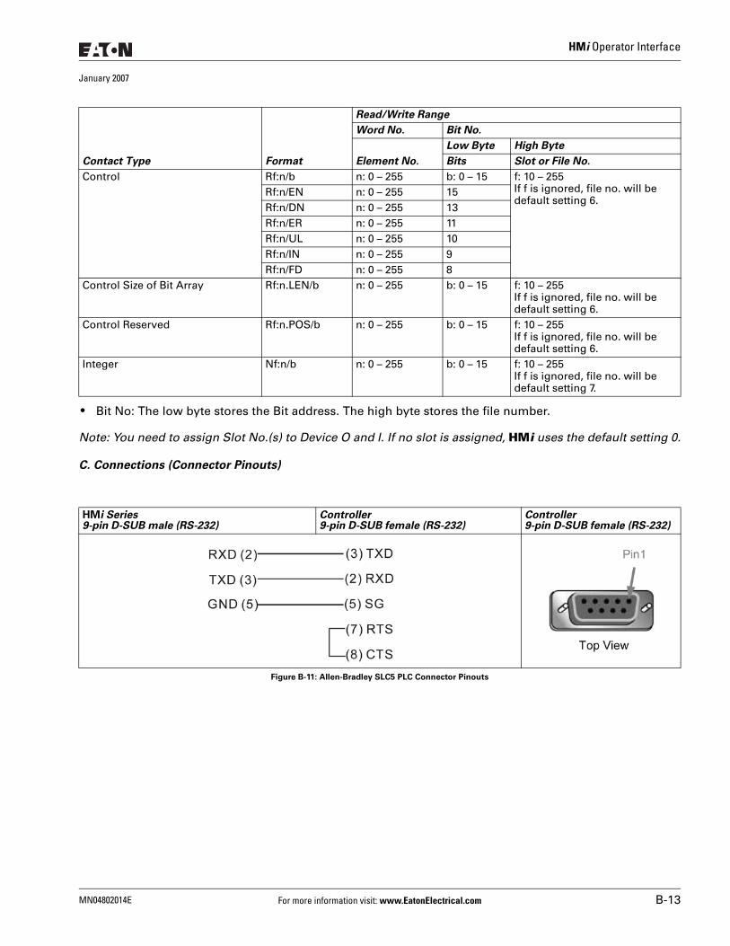
HMi Operator Interface
January 2007
● Bit No: The low byte stores the Bit address. The high byte stores the file number.
Note: You need to assign Slot No.(s) to Device O and I. If no slot is assigned, HMi uses the default setting 0.
C. Connections (Connector Pinouts)
Figure B-11: Allen-Bradley SLC5 PLC Connector Pinouts
Control Rf:n/b n: 0 – 255 b: 0 – 15 f: 10 – 255If f is ignored, file no. will be default setting 6.
Rf:n/EN n: 0 – 255 15Rf:n/DN n: 0 – 255 13Rf:n/ER n: 0 – 255 11Rf:n/UL n: 0 – 255 10Rf:n/IN n: 0 – 255 9Rf:n/FD n: 0 – 255 8
Control Size of Bit Array Rf:n.LEN/b n: 0 – 255 b: 0 – 15 f: 10 – 255If f is ignored, file no. will be default setting 6.
Control Reserved Rf:n.POS/b n: 0 – 255 b: 0 – 15 f: 10 – 255If f is ignored, file no. will be default setting 6.
Integer Nf:n/b n: 0 – 255 b: 0 – 15 f: 10 – 255If f is ignored, file no. will be default setting 7.
HMi Series9-pin D-SUB male (RS-232)
Controller9-pin D-SUB female (RS-232)
Controller9-pin D-SUB female (RS-232)
Contact Type Format
Read/Write Range
Word No. Bit No.
Element No.
Low Byte High Byte
Bits Slot or File No.
MN04802014E For more information visit: www.EatonElectrical.com B-13
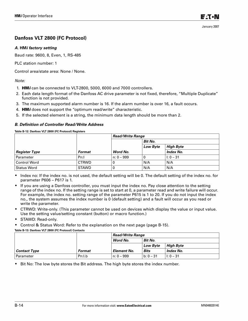
HMi Operator Interface
January 2007
Danfoss VLT 2800 (FC Protocol)
A. HMi factory setting
Baud rate: 9600, 8, Even, 1, RS-485
PLC station number: 1
Control area/state area: None / None.
Note:
1. HMi can be connected to VLT-2800, 5000, 6000 and 7000 controllers.2. Each data length format of the Danfoss AC drive parameter is not fixed, therefore, “Multiple Duplicate”
function is not provided.3. The maximum supported alarm number is 16. If the alarm number is over 16, a fault occurs.4. HMi does not support the “optimum read/write” characteristic.5. If the selected element is a string, the minimum data length should be more than 2.
B. Definition of Controller Read/Write Address
Table B-12: Danfoss VLT 2800 (FC Protocol) Registers
● Index no: If the index no. is not used, the default setting will be 0. The default setting of the index no. for parameter P606 – P617 is 1.
● If you are using a Danfoss controller, you must input the index no. Pay close attention to the setting range of the index no. If the setting range is set to start at 0, a parameter read and write failure will occur. For example, the index no. setting range of the parameter P615 is 1 to 20. If you do not input the index no., the system assumes the index number is 0 (default setting) and a fault will occur as you read or write the parameter.
● CTRWD: Write-only. (This parameter cannot be used on devices which display the value or input value. Use the setting value/setting constant (button) or macro function.)
● STAWD: Read-only. ● Control & Status Word: Refer to the explanation on the next page (page B-15).Table B-13: Danfoss VLT 2800 (FC Protocol) Contacts
● Bit No: The low byte stores the Bit address. The high byte stores the index number.
Register Type Format
Read/Write Range
Word No.
Bit No.
Low Byte High Byte
Index No.
Parameter Pn:I n: 0 – 999 0 I: 0 – 31Control Word CTRWD 0 N/A N/AStatus Word STAWD 0 N/A N/A
Contact Type Format
Read/Write Range
Word No. Bit No.
Element No.
Low Byte High Byte
Bits Index No.
Parameter Pn:I.b n: 0 – 999 b: 0 – 31 I: 0 – 31
B-14 For more information visit: www.EatonElectrical.com MN04802014E
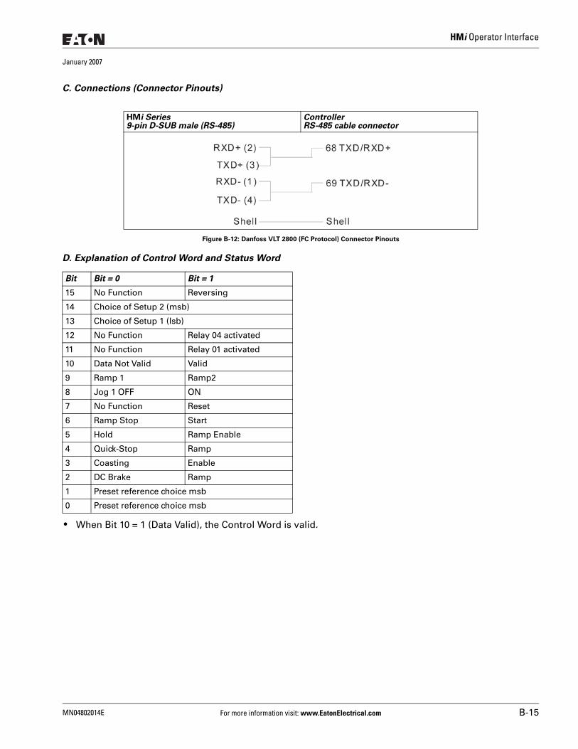
HMi Operator Interface
January 2007
C. Connections (Connector Pinouts)
Figure B-12: Danfoss VLT 2800 (FC Protocol) Connector Pinouts
D. Explanation of Control Word and Status Word
● When Bit 10 = 1 (Data Valid), the Control Word is valid.
HMi Series9-pin D-SUB male (RS-485)
ControllerRS-485 cable connector
Bit Bit = 0 Bit = 1
15 No Function Reversing
14 Choice of Setup 2 (msb)
13 Choice of Setup 1 (lsb)
12 No Function Relay 04 activated
11 No Function Relay 01 activated
10 Data Not Valid Valid
9 Ramp 1 Ramp2
8 Jog 1 OFF ON
7 No Function Reset
6 Ramp Stop Start
5 Hold Ramp Enable
4 Quick-Stop Ramp
3 Coasting Enable
2 DC Brake Ramp
1 Preset reference choice msb
0 Preset reference choice msb
MN04802014E For more information visit: www.EatonElectrical.com B-15
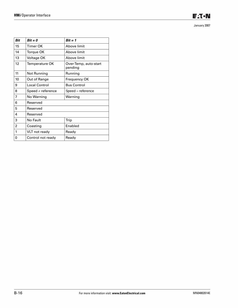
HMi Operator Interface
January 2007
Bit Bit = 0 Bit = 1
15 Timer OK Above limit
14 Torque OK Above limit
13 Voltage OK Above limit
12 Temperature OK Over-Temp, auto-start pending
11 Not Running Running
10 Out of Range Frequency OK
9 Local Control Bus Control
8 Speed ≠ reference Speed = reference
7 No Warning Warning
6 Reserved
5 Reserved
4 Reserved
3 No Fault Trip
2 Coasting Enabled
1 VLT not ready Ready
0 Control not ready Ready
B-16 For more information visit: www.EatonElectrical.com MN04802014E
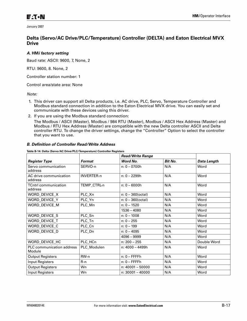
HMi Operator Interface
January 2007
Delta (Servo/AC Drive/PLC/Temperature) Controller (DELTA) and Eaton Electrical MVX Drive
A. HMi factory setting
Baud rate: ASCII: 9600, 7, None, 2
RTU: 9600, 8. None, 2
Controller station number: 1
Control area/state area: None
Note:
1. This driver can support all Delta products, i.e. AC drive, PLC, Servo, Temperature Controller and Modbus standard connection in addition to the Eaton Electrical MVX drive. You can easily set and communicate with these devices using this driver.
2. If you are using the Modbus standard connection:The Modbus / ASCII (Master), Modbus / 984 RTU (Master), Modbus / ASCII Hex Address (Master) and Modbus / RTU Hex Address (Master) are compatible with the new Delta controller ASCII and Delta controller RTU. To change the driver settings, change the “Controller” Option to select the controller that you want to use.
B. Definition of Controller Read/Write Address
Table B-14: Delta (Servo/AC Drive/PLC/Temperature) Controller Registers
Register Type Format
Read/Write Range
Data LengthWord No. Bit No.
Servo communication address
SERVO-n n: 0 – 0700h N/A Word
AC drive communication address
INVERTER-n n: 0 – 2299h N/A Word
TCntrl communication address
TEMP_CTRL-n n: 0 – 6000h N/A Word
WORD_DEVICE_X PLC_Xn n: 0 – 360(octal) N/A WordWORD_DEVICE_Y PLC_Yn n: 0 – 360(octal) N/A WordWORD_DEVICE_M PLC_Mn n: 0 – 1520 N/A Word
1536 – 4080 N/A WordWORD_DEVICE_S PLC_Sn n: 0 – 1008 N/A WordWORD_DEVICE_T PLC_Tn n: 0 – 255 N/A WordWORD_DEVICE_C PLC_Cn n: 0 – 199 N/A WordWORD_DEVICE_D PLC_Dn n: 0 – 4095 N/A Word
4096 – 9999 N/A WordWORD_DEVICE_HC PLC_HCn n: 200 – 255 N/A Double WordPLC communication address Module
PLC_Modulen n: 4000 – 4499h N/A Word
Output Registers RW-n n: 0 – FFFFh N/A WordInput Registers R-n n: 0 – FFFFh N/A WordOutput Registers Wn n: 40001 – 50000 N/A WordInput Registers Wn n: 30001 – 40000 N/A Word
MN04802014E For more information visit: www.EatonElectrical.com B-17
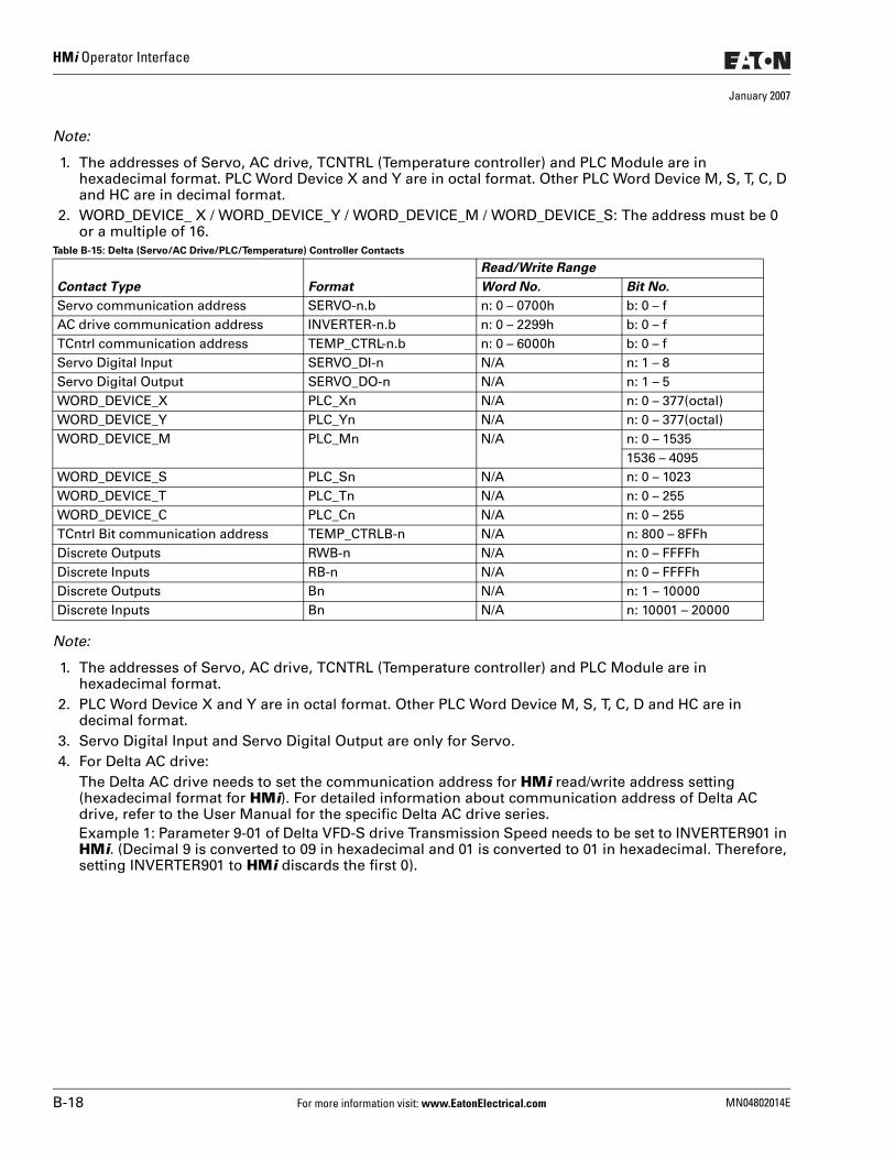
HMi Operator Interface
January 2007
Note:
1. The addresses of Servo, AC drive, TCNTRL (Temperature controller) and PLC Module are in hexadecimal format. PLC Word Device X and Y are in octal format. Other PLC Word Device M, S, T, C, D and HC are in decimal format.
2. WORD_DEVICE_ X / WORD_DEVICE_Y / WORD_DEVICE_M / WORD_DEVICE_S: The address must be 0 or a multiple of 16.
Table B-15: Delta (Servo/AC Drive/PLC/Temperature) Controller Contacts
Note:
1. The addresses of Servo, AC drive, TCNTRL (Temperature controller) and PLC Module are in hexadecimal format.
2. PLC Word Device X and Y are in octal format. Other PLC Word Device M, S, T, C, D and HC are in decimal format.
3. Servo Digital Input and Servo Digital Output are only for Servo.4. For Delta AC drive:
The Delta AC drive needs to set the communication address for HMi read/write address setting (hexadecimal format for HMi). For detailed information about communication address of Delta AC drive, refer to the User Manual for the specific Delta AC drive series.Example 1: Parameter 9-01 of Delta VFD-S drive Transmission Speed needs to be set to INVERTER901 in HMi. (Decimal 9 is converted to 09 in hexadecimal and 01 is converted to 01 in hexadecimal. Therefore, setting INVERTER901 to HMi discards the first 0).
Contact Type Format
Read/Write Range
Word No. Bit No.
Servo communication address SERVO-n.b n: 0 – 0700h b: 0 – fAC drive communication address INVERTER-n.b n: 0 – 2299h b: 0 – fTCntrl communication address TEMP_CTRL-n.b n: 0 – 6000h b: 0 – fServo Digital Input SERVO_DI-n N/A n: 1 – 8Servo Digital Output SERVO_DO-n N/A n: 1 – 5WORD_DEVICE_X PLC_Xn N/A n: 0 – 377(octal)WORD_DEVICE_Y PLC_Yn N/A n: 0 – 377(octal)WORD_DEVICE_M PLC_Mn N/A n: 0 – 1535
1536 – 4095WORD_DEVICE_S PLC_Sn N/A n: 0 – 1023WORD_DEVICE_T PLC_Tn N/A n: 0 – 255WORD_DEVICE_C PLC_Cn N/A n: 0 – 255TCntrl Bit communication address TEMP_CTRLB-n N/A n: 800 – 8FFhDiscrete Outputs RWB-n N/A n: 0 – FFFFhDiscrete Inputs RB-n N/A n: 0 – FFFFhDiscrete Outputs Bn N/A n: 1 – 10000Discrete Inputs Bn N/A n: 10001 – 20000
B-18 For more information visit: www.EatonElectrical.com MN04802014E
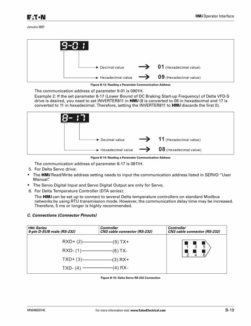
HMi Operator Interface
January 2007
Figure B-13: Reading a Parameter Communication Address
The communication address of parameter 9-01 is 0901H.Example 2: If the set parameter 8-17 (Lower Bound of DC Braking Start-up Frequency) of Delta VFD-S drive is desired, you need to set INVERTER811 in HMi (8 is converted to 08 in hexadecimal and 17 is converted to 11 in hexadecimal. Therefore, setting the INVERTER811 to HMi discards the first 0).
Figure B-14: Reading a Parameter Communication Address
The communication address of parameter 8-17 is 0811H.5. For Delta Servo drive:
● The HMi Read/Write address setting needs to input the communication address listed in SERVO “User Manual”.
● The Servo Digital Input and Servo Digital Output are only for Servo.6. For Delta Temperature Controller (DTA series):
The HMi can be set up to connect to several Delta temperature controllers on standard Modbus networks by using RTU transmission mode. However, the communication delay time may be increased. Therefore, 5 ms or longer is highly recommended.
C. Connections (Connector Pinouts)
Figure B-15: Delta Servo RS-232 Connection
HMi Series9-pin D-SUB male (RS-232)
ControllerCN3 cable connector (RS-232)
ControllerCN3 cable connector (RS-232)
MN04802014E For more information visit: www.EatonElectrical.com B-19
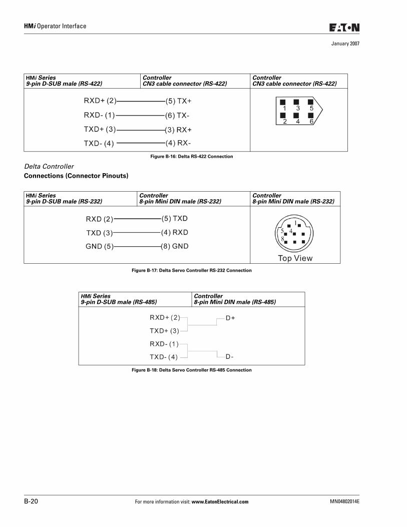
HMi Operator Interface
January 2007
Figure B-16: Delta RS-422 Connection
Delta ControllerConnections (Connector Pinouts)
Figure B-17: Delta Servo Controller RS-232 Connection
Figure B-18: Delta Servo Controller RS-485 Connection
HMi Series9-pin D-SUB male (RS-422)
ControllerCN3 cable connector (RS-422)
ControllerCN3 cable connector (RS-422)
HMi Series9-pin D-SUB male (RS-232)
Controller8-pin Mini DIN male (RS-232)
Controller8-pin Mini DIN male (RS-232)
HMi Series9-pin D-SUB male (RS-485)
Controller8-pin Mini DIN male (RS-485)
B-20 For more information visit: www.EatonElectrical.com MN04802014E
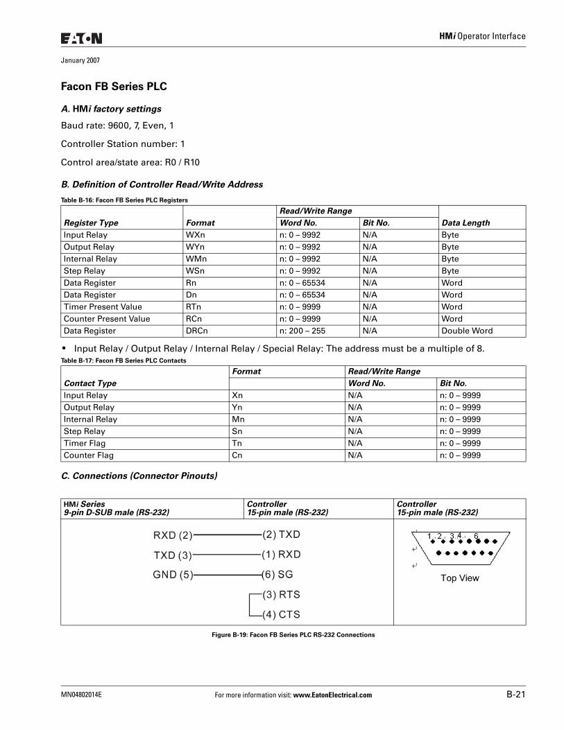
HMi Operator Interface
January 2007
Facon FB Series PLC
A. HMi factory settings
Baud rate: 9600, 7, Even, 1
Controller Station number: 1
Control area/state area: R0 / R10
B. Definition of Controller Read/Write Address
Table B-16: Facon FB Series PLC Registers
● Input Relay / Output Relay / Internal Relay / Special Relay: The address must be a multiple of 8.Table B-17: Facon FB Series PLC Contacts
C. Connections (Connector Pinouts)
Figure B-19: Facon FB Series PLC RS-232 Connections
Register Type Format
Read/Write Range
Data LengthWord No. Bit No.
Input Relay WXn n: 0 – 9992 N/A ByteOutput Relay WYn n: 0 – 9992 N/A ByteInternal Relay WMn n: 0 – 9992 N/A ByteStep Relay WSn n: 0 – 9992 N/A ByteData Register Rn n: 0 – 65534 N/A WordData Register Dn n: 0 – 65534 N/A WordTimer Present Value RTn n: 0 – 9999 N/A WordCounter Present Value RCn n: 0 – 9999 N/A WordData Register DRCn n: 200 – 255 N/A Double Word
Contact Type
Format Read/Write Range
Word No. Bit No.
Input Relay Xn N/A n: 0 – 9999Output Relay Yn N/A n: 0 – 9999Internal Relay Mn N/A n: 0 – 9999Step Relay Sn N/A n: 0 – 9999Timer Flag Tn N/A n: 0 – 9999Counter Flag Cn N/A n: 0 – 9999
HMi Series9-pin D-SUB male (RS-232)
Controller15-pin male (RS-232)
Controller15-pin male (RS-232)
MN04802014E For more information visit: www.EatonElectrical.com B-21
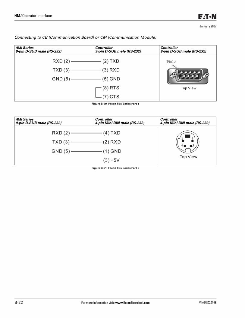
HMi Operator Interface
January 2007
Connecting to CB (Communication Board) or CM (Communication Module)
Figure B-20: Facon FBs Series Port 1
Figure B-21: Facon FBs Series Port 0
HMi Series9-pin D-SUB male (RS-232)
Controller9-pin D-SUB male (RS-232)
Controller9-pin D-SUB male (RS-232)
HMi Series9-pin D-SUB male (RS-232)
Controller4-pin Mini DIN male (RS-232)
Controller4-pin Mini DIN male (RS-232)
B-22 For more information visit: www.EatonElectrical.com MN04802014E
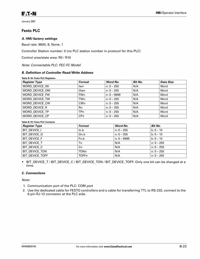
HMi Operator Interface
January 2007
Festo PLC
A. HMi factory settings
Baud rate: 9600, 8, None, 1
Controller Station number: 0 (no PLC station number in protocol for this PLC)
Control area/state area: R0 / R10
Note: Connectable PLC: FEC-FC Model
B. Definition of Controller Read/Write Address
Table B-18: Festo PLC Registers
Table B-19: Festo PLC Contacts
● BIT_DEVICE_T / BIT_DEVICE_C / BIT_DEVICE_TON / BIT_DEVICE_TOFF: Only one bit can be changed at a time.
C. Connections
Note:
1. Communication port of the PLC: COM port2. Use the dedicated cable for FESTO controllers and a cable for transferring TTL to RS-232, connect to the
6-pin RJ-12 connector at the PLC side.
Register Type Format Word No. Bit No. Data Size
WORD_DEVICE_IW Iwn n: 0 – 255 N/A WordWORD_DEVICE_OW Own n: 0 – 255 N/A WordWORD_DEVICE_FW FWn n: 0 – 9999 N/A WordWORD_DEVICE_TW TWn n: 0 – 255 N/A WordWORD_DEVICE_CW CWn n: 0 – 255 N/A WordWORD_DEVICE_R Rn n: 0 – 255 N/A WordWORD_DEVICE_TP TPn n: 0 – 255 N/A WordWORD_DEVICE_CP CPn n: 0 – 255 N/A Word
Register Type Format Word No. Bit No.
BIT_DEVICE_I In.b n: 0 – 255 b: 0 – 15BIT_DEVICE_O On.b n: 0 – 255 b: 0 – 15BIT_DEVICE_F Fn.b n: 0 – 9999 b: 0 – 15BIT_DEVICE_T Tn N/A n: 0 – 255BIT_DEVICE_C Cn N/A n: 0 – 255BIT_DEVICE_TON TONn N/A n: 0 – 255BIT_DEVICE_TOFF TOFFn N/A n: 0 – 255
MN04802014E For more information visit: www.EatonElectrical.com B-23
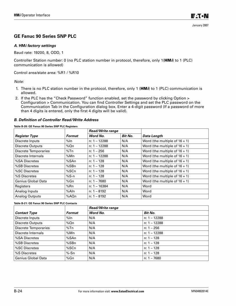
HMi Operator Interface
January 2007
GE Fanuc 90 Series SNP PLC
A. HMi factory settings
Baud rate: 19200, 8, ODD, 1
Controller Station number: 0 (no PLC station number in protocol, therefore, only 1(HMi) to 1 (PLC) communication is allowed)
Control area/state area: %R1 / %R10
Note:
1. There is no PLC station number in the protocol, therefore, only 1 (HMi) to 1 (PLC) communication is allowed.
2. If the PLC has the “Check Password” function enabled, set the password by clicking Option > Configuration > Communication. You can find Controller Settings and set the PLC password on the Communication Tab in the Configuration dialog box. Enter a 4-digit password (If a password of more than 4 digits is entered, only the first 4 digits will be valid).
B. Definition of Controller Read/Write Address
Table B-20: GE Fanuc 90 Series SNP PLC Registers
Table B-21: GE Fanuc 90 Series SNP PLC Contacts
Register Type Format
Read/Write range
Data LengthWord No. Bit No.
Discrete Inputs %In n: 1 – 12288 N/A Word (the multiple of 16 + 1)Discrete Outputs %Qn n: 1 – 12288 N/A Word (the multiple of 16 + 1)Discrete Temporaries %Tn n: 1 – 256 N/A Word (the multiple of 16 + 1)Discrete Internals %Mn n: 1 – 12288 N/A Word (the multiple of 16 + 1)%SA Discretes %SAn n: 1 – 128 N/A Word (the multiple of 16 + 1)%SB Discretes %SBn n: 1 – 128 N/A Word (the multiple of 16 + 1)%SC Discretes %SCn n: 1 – 128 N/A Word (the multiple of 16 + 1)%S Discretes %S-n n: 1 – 128 N/A Word (the multiple of 16 + 1)Genius Global Data %Gn n: 1 – 7680 N/A Word (the multiple of 16 + 1)Registers %Rn n: 1 – 16384 N/A WordAnalog Inputs %AIn n: 1 – 8192 N/A WordAnalog Outputs %AQn n: 1 – 8192 N/A Word
Contact Type Format
Read/Write range
Word No. Bit No.
Discrete Inputs %In N/A n: 1 – 12288Discrete Outputs %Qn N/A n: 1 – 12288Discrete Temporaries %Tn N/A n: 1 – 256Discrete Internals %Mn N/A n: 1 – 12288%SA Discretes %SAn N/A n: 1 – 128%SB Discretes %SBn N/A n: 1 – 128%SC Discretes %SCn N/A n: 1 – 128%S Discretes %-Sn N/A n: 1 – 128Genius Global Data %Gn N/A n: 1 – 7680
B-24 For more information visit: www.EatonElectrical.com MN04802014E
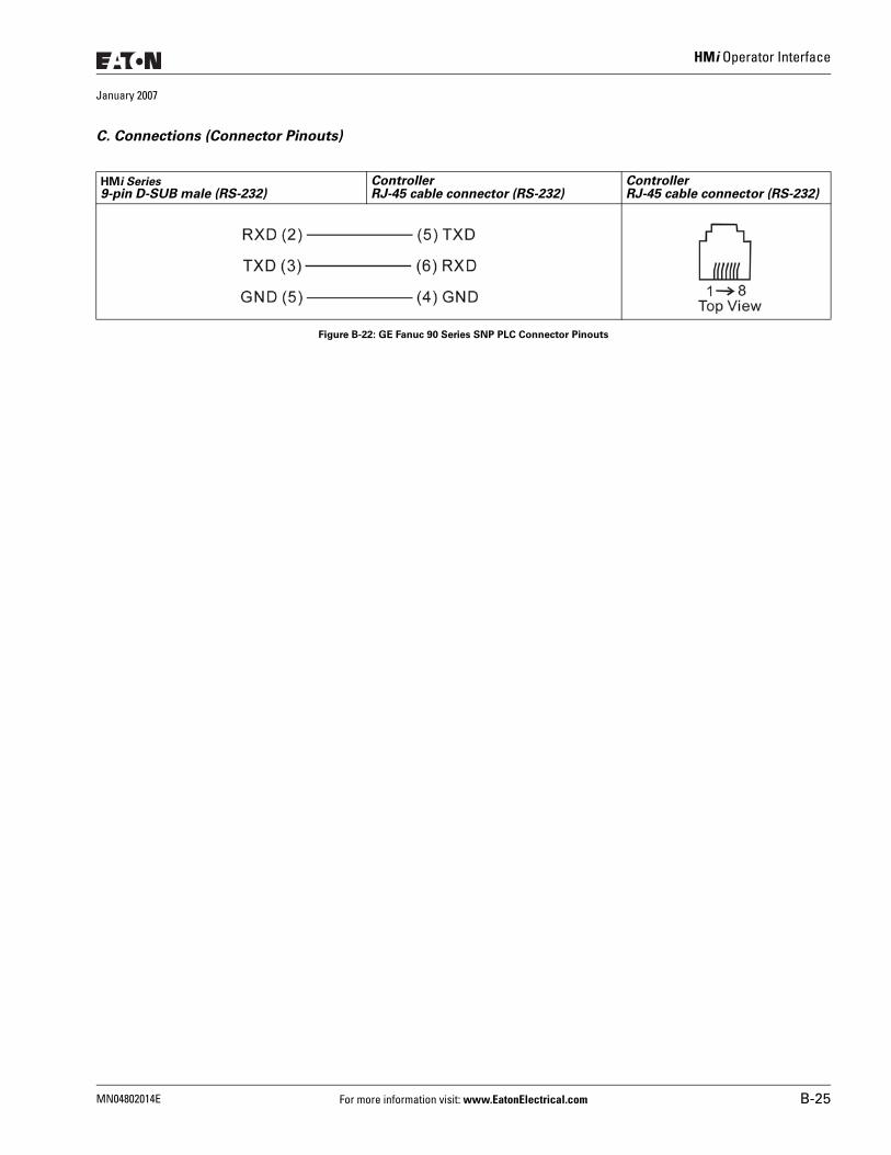
HMi Operator Interface
January 2007
C. Connections (Connector Pinouts)
Figure B-22: GE Fanuc 90 Series SNP PLC Connector Pinouts
HMi Series9-pin D-SUB male (RS-232)
ControllerRJ-45 cable connector (RS-232)
ControllerRJ-45 cable connector (RS-232)
MN04802014E For more information visit: www.EatonElectrical.com B-25
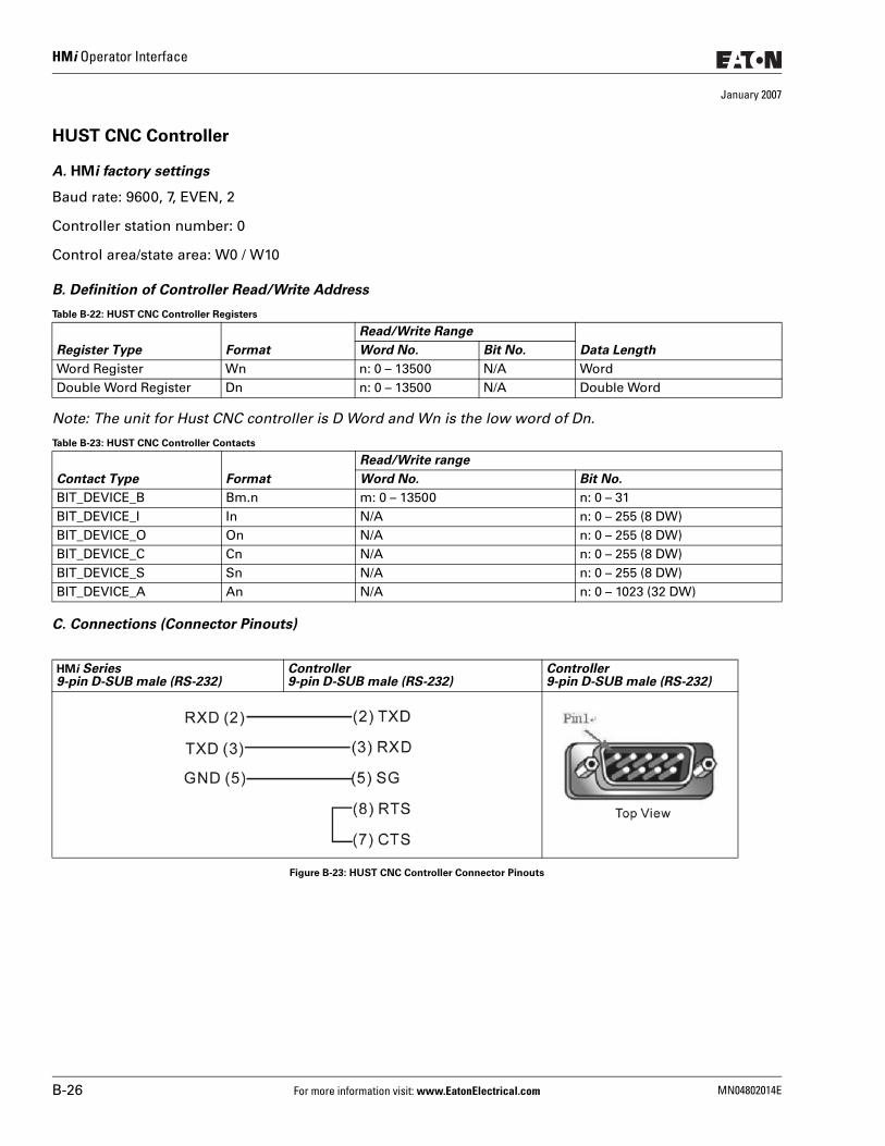
HMi Operator Interface
January 2007
HUST CNC Controller
A. HMi factory settings
Baud rate: 9600, 7, EVEN, 2
Controller station number: 0
Control area/state area: W0 / W10
B. Definition of Controller Read/Write Address
Table B-22: HUST CNC Controller Registers
Note: The unit for Hust CNC controller is D Word and Wn is the low word of Dn.
Table B-23: HUST CNC Controller Contacts
C. Connections (Connector Pinouts)
Figure B-23: HUST CNC Controller Connector Pinouts
Register Type Format
Read/Write Range
Data LengthWord No. Bit No.
Word Register Wn n: 0 – 13500 N/A WordDouble Word Register Dn n: 0 – 13500 N/A Double Word
Contact Type Format
Read/Write range
Word No. Bit No.
BIT_DEVICE_B Bm.n m: 0 – 13500 n: 0 – 31BIT_DEVICE_I In N/A n: 0 – 255 (8 DW)BIT_DEVICE_O On N/A n: 0 – 255 (8 DW)BIT_DEVICE_C Cn N/A n: 0 – 255 (8 DW)BIT_DEVICE_S Sn N/A n: 0 – 255 (8 DW)BIT_DEVICE_A An N/A n: 0 – 1023 (32 DW)
HMi Series9-pin D-SUB male (RS-232)
Controller9-pin D-SUB male (RS-232)
Controller9-pin D-SUB male (RS-232)
B-26 For more information visit: www.EatonElectrical.com MN04802014E
HMi Operator Interface
January 2007
Jetter Nano Series PLC
A. HMi factory settings
Baud rate: 9600, 8, EVEN, 1 (RS-232)
Controller station number: 0 (no PLC station number in protocol, therefore, only 1 (HMi) to 1 (PLC) communication is allowed)
Control area/state area: WR0 / WR10
Note:
1. There is no PLC station number in protocol, only 1 (HMi) to 1 (PLC) communication is allowed.2. Only 1 Bit or 1 Word will be transferred for each communication.3. In general, each register occupies maximum of 24 bits. However, some registers only occupy 8 bits.4. Because the initial start up time of this controller is longer, it is recommended to set the HMi startup
delay time to 10 seconds.5. When the register R is used for Double Word device, set its format as signed format. (The default format
in Screen Editor is the assigned format).
B. Definition of Controller Read/Write Address
Registers ● Only the first 16 bits are used for WRn registers. ● Only the first 24 bits are used for Rn registers. The highest 8 bits (Bit 24 – 31) are set to 0 by the default
setting. ● 24-bit Integer: In decimal format, the range is -8388608 – +8388607. In hexadecimal format, the range is
0x000000 – 0xFFFFFF.
Note:
The difference between WRn and Rn:
● When using devices where the data length is in Word, only Bit 0 – 15 are valid for both of WRn and Rn registers.
● When using devices where the data length is in Double Word: If the read/write address format is set to WRn, the Bit 0 – 15 of WRn register is the low word of a read/write value, the Bit 0 – 15 of WRn+1 register is the high word of a read/write value. If the read/write address format is set to Rn, only Bit 0 – 23 are valid for Rn registers.(Notice: As the Jetter controller is a 24-bit format controller, the valid setting range is 24 bits. If you exceed this range, HMi will stop the read/write operation and display “…..Value is Incorrect” on the screen. Do not set any bit for Bit24 – Bit31 as Bit24 – Bit31 cannot be written.
● When using devices where the data length is in m Words: If the read/write address format is set to WRn, the Bit 0 – 15 of WRn register is the lowest word of a read/write value and the Bit 0 – 15 of WRn+m-1 register is the highest word of a read/write value.If the read/write address format is set to Rn, the Bit 0 – 23 of Rn register is the lowest word of a read/write value and the Bit 0 – 23 of Rn+1 register is the highest word of a read/write value.Each register is regards as a “Double Word”. The value of Bit24 – Bit31 is 0.
MN04802014E For more information visit: www.EatonElectrical.com B-27
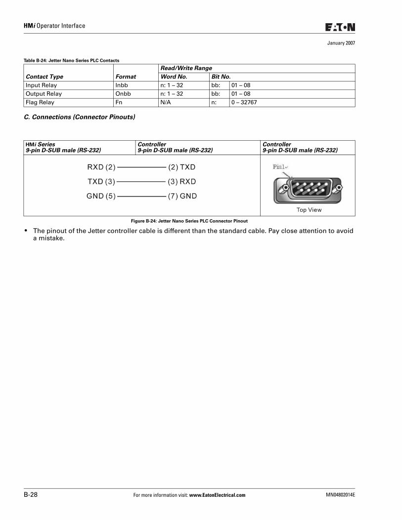
HMi Operator Interface
January 2007
Table B-24: Jetter Nano Series PLC Contacts
C. Connections (Connector Pinouts)
Figure B-24: Jetter Nano Series PLC Connector Pinout
● The pinout of the Jetter controller cable is different than the standard cable. Pay close attention to avoid a mistake.
Contact Type Format
Read/Write Range
Word No. Bit No.
Input Relay Inbb n: 1 – 32 bb: 01 – 08Output Relay Onbb n: 1 – 32 bb: 01 – 08Flag Relay Fn N/A n: 0 – 32767
HMi Series9-pin D-SUB male (RS-232)
Controller9-pin D-SUB male (RS-232)
Controller9-pin D-SUB male (RS-232)
B-28 For more information visit: www.EatonElectrical.com MN04802014E
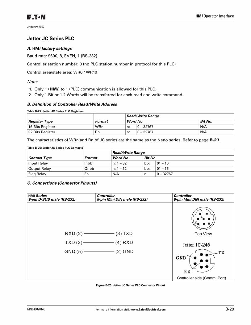
HMi Operator Interface
January 2007
Jetter JC Series PLC
A. HMi factory settings
Baud rate: 9600, 8, EVEN, 1 (RS-232)
Controller station number: 0 (no PLC station number in protocol for this PLC)
Control area/state area: WR0 / WR10
Note:
1. Only 1 (HMi) to 1 (PLC) communication is allowed for this PLC.2. Only 1 Bit or 1-2 Words will be transferred for each read and write command.
B. Definition of Controller Read/Write Address
Table B-25: Jetter JC Series PLC Registers
The characteristics of WRn and Rn of JC series are the same as the Nano series. Refer to page B-27.
Table B-26: Jetter JC Series PLC Contacts
C. Connections (Connector Pinouts)
Figure B-25: Jetter JC Series PLC Connector Pinout
Register Type Format
Read/Write Range
Word No. Bit No.
16 Bits Register WRn n: 0 – 32767 N/A32 Bits Register Rn n: 0 – 32767 N/A
Contact Type Format
Read/Write Range
Word No. Bit No.
Input Relay Inbb n: 1 – 32 bb: 01 – 16Output Relay Onbb n: 1 – 32 bb: 01 – 16Flag Relay Fn N/A n: 0 – 32767
HMi Series9-pin D-SUB male (RS-232)
Controller8-pin Mini DIN male (RS-232)
Controller8-pin Mini DIN male (RS-232)
MN04802014E For more information visit: www.EatonElectrical.com B-29
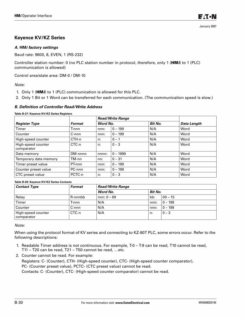
HMi Operator Interface
January 2007
Keyence KV/KZ Series
A. HMi factory settings
Baud rate: 9600, 8, EVEN, 1 (RS-232)
Controller station number: 0 (no PLC station number in protocol, therefore, only 1 (HMi) to 1 (PLC) communication is allowed)
Control area/state area: DM-0 / DM-10
Note:
1. Only 1 (HMi) to 1 (PLC) communication is allowed for this PLC.2. Only 1 Bit or 1 Word can be transferred for each communication. (The communication speed is slow.)
B. Definition of Controller Read/Write Address
Table B-27: Keyence KV/KZ Series Registers
Table B-28: Keyence KV/KZ Series Contacts
Note:
When using the protocol format of KV series and connecting to KZ-80T PLC, some errors occur. Refer to the following descriptions:
1. Readable Timer address is not continuous. For example, T-0 – T-9 can be read, T10 cannot be read, T11 – T20 can be read, T21 – T50 cannot be read, …etc.
2. Counter cannot be read. For example:Registers: C- (Counter), CTH- (High-speed counter), CTC- (High-speed counter comparator),PC- (Counter preset value), PCTC- (CTC preset value) cannot be read.Contacts: C- (Counter), CTC- (High-speed counter comparator) cannot be read.
Register Type Format
Read/Write Range
Data LengthWord No. Bit No.
Timer T-nnn nnn: 0 – 199 N/A WordCounter C-nnn nnn: 0 – 199 N/A WordHigh-speed counter CTH-n n: 0 – 1 N/A WordHigh-speed counter comparator
CTC-n n: 0 – 3 N/A Word
Data memory DM-nnnn nnnn: 0 – 1999 N/A WordTemporary data memory TM-nn nn: 0 – 31 N/A WordTimer preset value PT-nnn nnn: 0 – 199 N/A WordCounter preset value PC-nnn nnn: 0 – 199 N/A WordCTC preset value PCTC-n n: 0 – 3 N/A Word
Contact Type Format Read/Write Range
Word No. Bit No.
Relay R-nnnbb nnn: 0 – 69 bb: 00 – 15Timer T-nnn N/A nnn: 0 – 199Counter C-nnn N/A nnn: 0 – 199High-speed counter comparator
CTC-n N/A n: 0 – 3
B-30 For more information visit: www.EatonElectrical.com MN04802014E
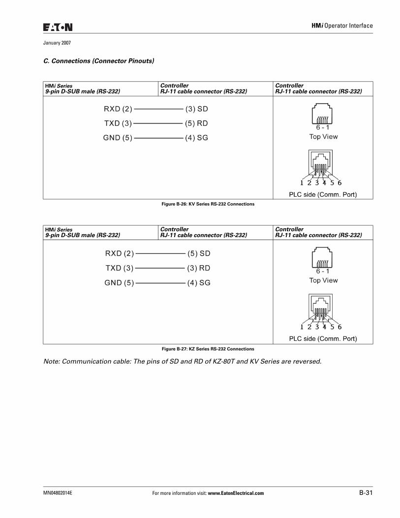
HMi Operator Interface
January 2007
C. Connections (Connector Pinouts)
Figure B-26: KV Series RS-232 Connections
Figure B-27: KZ Series RS-232 Connections
Note: Communication cable: The pins of SD and RD of KZ-80T and KV Series are reversed.
HMi Series9-pin D-SUB male (RS-232)
ControllerRJ-11 cable connector (RS-232)
ControllerRJ-11 cable connector (RS-232)
HMi Series9-pin D-SUB male (RS-232)
ControllerRJ-11 cable connector (RS-232)
ControllerRJ-11 cable connector (RS-232)
MN04802014E For more information visit: www.EatonElectrical.com B-31
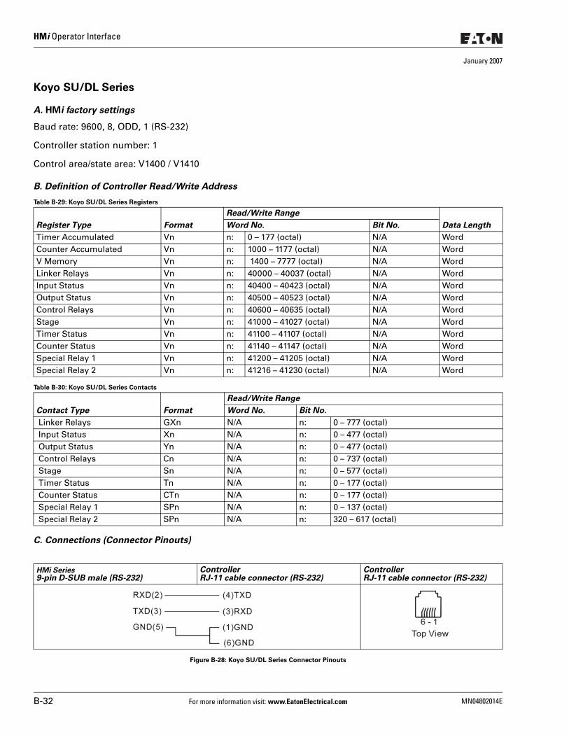
HMi Operator Interface
January 2007
Koyo SU/DL Series
A. HMi factory settings
Baud rate: 9600, 8, ODD, 1 (RS-232)
Controller station number: 1
Control area/state area: V1400 / V1410
B. Definition of Controller Read/Write Address
Table B-29: Koyo SU/DL Series Registers
Table B-30: Koyo SU/DL Series Contacts
C. Connections (Connector Pinouts)
Figure B-28: Koyo SU/DL Series Connector Pinouts
Register Type Format
Read/Write Range
Data LengthWord No. Bit No.
Timer Accumulated Vn n: 0 – 177 (octal) N/A WordCounter Accumulated Vn n: 1000 – 1177 (octal) N/A WordV Memory Vn n: 1400 – 7777 (octal) N/A WordLinker Relays Vn n: 40000 – 40037 (octal) N/A WordInput Status Vn n: 40400 – 40423 (octal) N/A WordOutput Status Vn n: 40500 – 40523 (octal) N/A WordControl Relays Vn n: 40600 – 40635 (octal) N/A WordStage Vn n: 41000 – 41027 (octal) N/A WordTimer Status Vn n: 41100 – 41107 (octal) N/A WordCounter Status Vn n: 41140 – 41147 (octal) N/A WordSpecial Relay 1 Vn n: 41200 – 41205 (octal) N/A WordSpecial Relay 2 Vn n: 41216 – 41230 (octal) N/A Word
Contact Type Format
Read/Write Range
Word No. Bit No.
Linker Relays GXn N/A n: 0 – 777 (octal) Input Status Xn N/A n: 0 – 477 (octal) Output Status Yn N/A n: 0 – 477 (octal) Control Relays Cn N/A n: 0 – 737 (octal) Stage Sn N/A n: 0 – 577 (octal) Timer Status Tn N/A n: 0 – 177 (octal) Counter Status CTn N/A n: 0 – 177 (octal) Special Relay 1 SPn N/A n: 0 – 137 (octal) Special Relay 2 SPn N/A n: 320 – 617 (octal)
HMi Series9-pin D-SUB male (RS-232)
ControllerRJ-11 cable connector (RS-232)
ControllerRJ-11 cable connector (RS-232)
B-32 For more information visit: www.EatonElectrical.com MN04802014E
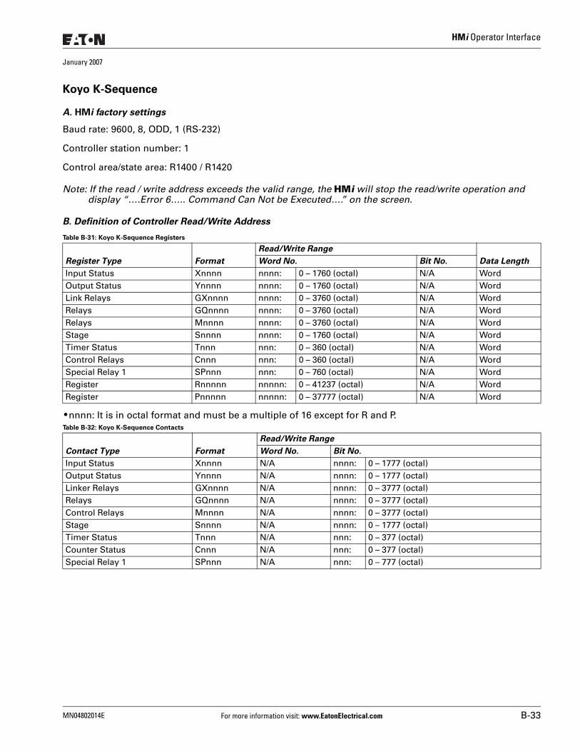
HMi Operator Interface
January 2007
Koyo K-Sequence
A. HMi factory settings
Baud rate: 9600, 8, ODD, 1 (RS-232)
Controller station number: 1
Control area/state area: R1400 / R1420
Note: If the read / write address exceeds the valid range, the HMi will stop the read/write operation and display “….Error 6….. Command Can Not be Executed….” on the screen.
B. Definition of Controller Read/Write Address
Table B-31: Koyo K-Sequence Registers
● nnnn: It is in octal format and must be a multiple of 16 except for R and P.Table B-32: Koyo K-Sequence Contacts
Register Type Format
Read/Write Range
Data LengthWord No. Bit No.
Input Status Xnnnn nnnn: 0 – 1760 (octal) N/A WordOutput Status Ynnnn nnnn: 0 – 1760 (octal) N/A WordLink Relays GXnnnn nnnn: 0 – 3760 (octal) N/A WordRelays GQnnnn nnnn: 0 – 3760 (octal) N/A WordRelays Mnnnn nnnn: 0 – 3760 (octal) N/A WordStage Snnnn nnnn: 0 – 1760 (octal) N/A WordTimer Status Tnnn nnn: 0 – 360 (octal) N/A WordControl Relays Cnnn nnn: 0 – 360 (octal) N/A WordSpecial Relay 1 SPnnn nnn: 0 – 760 (octal) N/A WordRegister Rnnnnn nnnnn: 0 – 41237 (octal) N/A WordRegister Pnnnnn nnnnn: 0 – 37777 (octal) N/A Word
Contact Type Format
Read/Write Range
Word No. Bit No.
Input Status Xnnnn N/A nnnn: 0 – 1777 (octal)Output Status Ynnnn N/A nnnn: 0 – 1777 (octal)Linker Relays GXnnnn N/A nnnn: 0 – 3777 (octal)Relays GQnnnn N/A nnnn: 0 – 3777 (octal)Control Relays Mnnnn N/A nnnn: 0 – 3777 (octal)Stage Snnnn N/A nnnn: 0 – 1777 (octal)Timer Status Tnnn N/A nnn: 0 – 377 (octal)Counter Status Cnnn N/A nnn: 0 – 377 (octal)Special Relay 1 SPnnn N/A nnn: 0 – 777 (octal)
MN04802014E For more information visit: www.EatonElectrical.com B-33
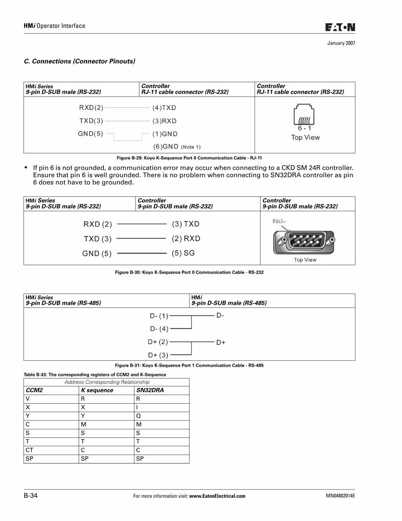
HMi Operator Interface
January 2007
C. Connections (Connector Pinouts)
Figure B-29: Koyo K-Sequence Port 0 Communication Cable - RJ-11
● If pin 6 is not grounded, a communication error may occur when connecting to a CKD SM 24R controller. Ensure that pin 6 is well grounded. There is no problem when connecting to SN32DRA controller as pin 6 does not have to be grounded.
Figure B-30: Koyo K-Sequence Port 0 Communication Cable - RS-232
Figure B-31: Koyo K-Sequence Port 1 Communication Cable - RS-485
Table B-33: The corresponding registers of CCM2 and K-Sequence
HMi Series9-pin D-SUB male (RS-232)
ControllerRJ-11 cable connector (RS-232)
ControllerRJ-11 cable connector (RS-232)
HMi Series9-pin D-SUB male (RS-232)
Controller9-pin D-SUB male (RS-232)
Controller9-pin D-SUB male (RS-232)
HMi Series9-pin D-SUB male (RS-485)
HMi9-pin D-SUB male (RS-485)
Address Corresponding Relationship
CCM2 K sequence SN32DRA
V R RX X IY Y QC M MS S ST T TCT C CSP SP SP
B-34 For more information visit: www.EatonElectrical.com MN04802014E
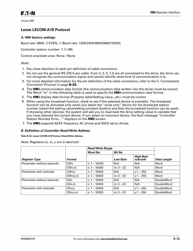
HMi Operator Interface
January 2007
Lenze LECOM-A/B Protocol
A. HMi factory settings
Baud rate: 9600, 7, EVEN, 1 (Baud rate: 1200/2400/4800/9600/19200)
Controller station number: 1 (1–99)
Control area/state area: None / None
Note:
1. Pay close attention to each pin definition of cable connectors.2. Do not use the general RS-232 5-pin cable. If pin 2, 3, 5, 7, 8 are all connected to the drive, the drive can
not recognize the communication signal and cannot identify what kind of communication it is. 3. For more detailed information for the pin definition of the cable connectors, refer to the C. Connections
(Connector Pinouts) in page B-25.4. The HMi communication data format (the communication data written into the drive) must be correct.
The Word “m” in the following table is used to specify the HMi communication data format.5. The HMi display data format (Property table/Setting value...etc.) must be correct.6. When using the broadcast function, check to see if the selected device is available. The broadcast
function can be activated only when you select the “write only” device for the broadcast station number (select the setting value/setting constant [button] and then the broadcast function can be used). If choosing other devices, the system will ask you to read back the drive setting value to validate that you have selected the correct device. If you select an incorrect device, the fault message “Controller Station Number Error…” displays on the HMi screen.
7. The HMi supports 82XX frequency AC drives and 93XX servo drives.
B. Definition of Controller Read/Write Address
Table B-34: Lenze LECOM-A/B Protocol Read/Write Address
Note: Registers (n, m, y are in decimal)
Register Type Format
Read/Write Range
Data Length
Word No. Bit No.
Low ByteHigh Bytesubcode
Parameter without subcode CWn n: 1 – 10000 N/A N/A WordCWn.m n: 1 – 10000 m: 0 – 23 N/A Word
Parameter with subcode CWn/y n: 1 – 10000 N/A y:1 – 255 WordCWn/y.m n: 1 – 10000 m: 0 – 23 y:1 – 255 Word
Parameter without subcode CDn n: 1 – 10000 N/A N/A DoubleWordCDn.m n: 1 – 10000 m: 0 – 23 N/A DoubleWord
Parameter with subcode CDn/y n: 1 – 10000 N/A y:1 – 255 DoubleWordCDn/y.m n: 1 – 10000 m: 0 – 23 y:1 – 255 DoubleWord
MN04802014E For more information visit: www.EatonElectrical.com B-35
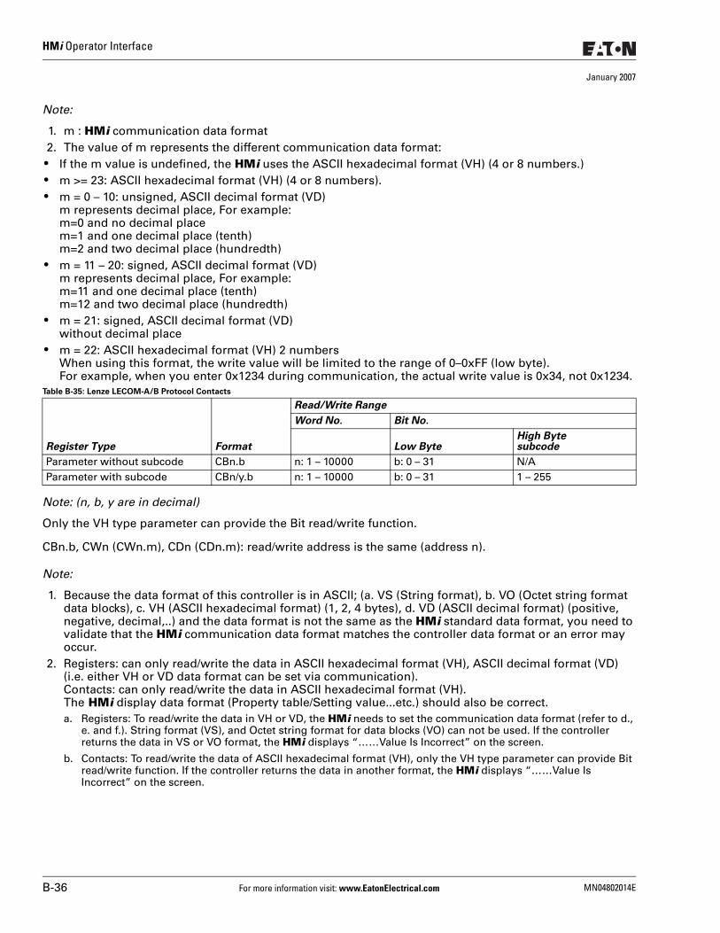
HMi Operator Interface
January 2007
Note:
1. m : HMi communication data format2. The value of m represents the different communication data format:
● If the m value is undefined, the HMi uses the ASCII hexadecimal format (VH) (4 or 8 numbers.) ● m >= 23: ASCII hexadecimal format (VH) (4 or 8 numbers). ● m = 0 – 10: unsigned, ASCII decimal format (VD)
m represents decimal place, For example:m=0 and no decimal placem=1 and one decimal place (tenth)m=2 and two decimal place (hundredth)
● m = 11 – 20: signed, ASCII decimal format (VD)m represents decimal place, For example:m=11 and one decimal place (tenth)m=12 and two decimal place (hundredth)
● m = 21: signed, ASCII decimal format (VD)without decimal place
● m = 22: ASCII hexadecimal format (VH) 2 numbersWhen using this format, the write value will be limited to the range of 0–0xFF (low byte).For example, when you enter 0x1234 during communication, the actual write value is 0x34, not 0x1234.
Table B-35: Lenze LECOM-A/B Protocol Contacts
Note: (n, b, y are in decimal)
Only the VH type parameter can provide the Bit read/write function.
CBn.b, CWn (CWn.m), CDn (CDn.m): read/write address is the same (address n).
Note:
1. Because the data format of this controller is in ASCII; (a. VS (String format), b. VO (Octet string format data blocks), c. VH (ASCII hexadecimal format) (1, 2, 4 bytes), d. VD (ASCII decimal format) (positive, negative, decimal,..) and the data format is not the same as the HMi standard data format, you need to validate that the HMi communication data format matches the controller data format or an error may occur.
2. Registers: can only read/write the data in ASCII hexadecimal format (VH), ASCII decimal format (VD) (i.e. either VH or VD data format can be set via communication).Contacts: can only read/write the data in ASCII hexadecimal format (VH).The HMi display data format (Property table/Setting value...etc.) should also be correct.a. Registers: To read/write the data in VH or VD, the HMi needs to set the communication data format (refer to d.,
e. and f.). String format (VS), and Octet string format for data blocks (VO) can not be used. If the controller returns the data in VS or VO format, the HMi displays “……Value Is Incorrect” on the screen.
b. Contacts: To read/write the data of ASCII hexadecimal format (VH), only the VH type parameter can provide Bit read/write function. If the controller returns the data in another format, the HMi displays “……Value Is Incorrect” on the screen.
Register Type Format
Read/Write Range
Word No. Bit No.
Low ByteHigh Bytesubcode
Parameter without subcode CBn.b n: 1 – 10000 b: 0 – 31 N/AParameter with subcode CBn/y.b n: 1 – 10000 b: 0 – 31 1 – 255
B-36 For more information visit: www.EatonElectrical.com MN04802014E
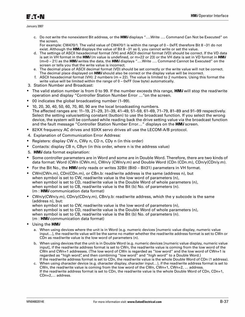
HMi Operator Interface
January 2007
c. Do not write the nonexistent Bit address, or the HMi displays “….Write …. Command Can Not be Executed” on the screen. For example: CW470/1. The valid value of CW470/1 is within the range of 0 – 0xFF, therefore Bit 8 –31 do not exist. Although the HMi displays the value of Bit 8 –31 as 0, you cannot write or set the value.
d. The settings of ASCII hexadecimal format (VH) and ASCII decimal format (VD) should be correct. If the VD data is set in VH format in the HMi (m value is undefined, or m=22 or 23) or the VH data is set in VD format in HMi (m=0 – 21) as the HMi writes the data, the HMi displays “….Write …. Command Cannot be Executed” on the screen or tells you that the write value is incorrect.
e. The decimal place of ASCII decimal format (VD) should be set correctly or the write value will not be correct. The decimal place displayed on HMi should also be correct or the display value will be incorrect.
f. ASCII hexadecimal format (VH): 2 numbers (m = 22). The value is limited to 2 numbers. Using this format the write value will be limited within the range of 0 – 0xFF (low byte) automatically.
3. Station Number and Broadcast: ● The valid station number is from 0 to 99. If the number exceeds this range, HMi will stop the read/write
operation and display “Controller Station Number Error …”on the screen. ● 00 indicates the global broadcasting number (1–99). ● 10, 20, 30, 40, 50, 60, 70, 80, 90 are the local broadcasting numbers.
The affected ranges are: 11–19, 21–29, 31–39, 41–49, 51–59, 61–69, 71–79, 81–89 and 91–99 respectively. Select the setting value/setting constant (button) to use the broadcast function. If you select the wrong device, the system will be confused while reading back the drive setting value via the broadcast function and the fault message “Controller Station Number Error…” displays on the HMi screen.
● 82XX frequency AC drives and 93XX servo drives all use the LECOM-A/B protocol.4. Explanation of Communication Error Address:
● Registers: display CW n, CWy n, CD n, CDy n (in this order) ● Contacts: display CB n, CByn (in this order, where n is the address value)5. HMi data format explanation:
● Some controller parameters are in Word and some are in Double Word. Therefore, there are two kinds of data format: Word (CWn (CWn.m), CWn/y (CWn/y.m) and Double Word (CDn (CDn.m), CDn/y(CDn/y.m).
● For the Bit No., the HMi only reads or writes 32Bit (Bit0 – Bit31) parameters in VH format. ● CWn(CWn.m), CDn(CDn.m), or CBn.b: read/write address is the same (address n), but
when symbol is set to CW, read/write value is the low word of parameters (n),when symbol is set to CD, read/write value is the Double Word of whole parameters (n),when symbol is set to CB, read/write value is the Bit (b) No. of parameters (n).(m : HMi communication data format)
● CWn/y(CWn/y.m), CDn/y(CDn/y.m), CBn/y.b: read/write address, which the y subcode is the same (address n), but:when symbol is set to CW, read/write value is the low word of parameters (n),when symbol is set to CD, read/write value is the Double Word of whole parameters (n),when symbol is set to CB, read/write value is the Bit (b) No. of parameters (n).(m : HMi communication data format)
● Using the HMia. When using devices where the unit is in Word (e.g. numeric devices [numeric value display, numeric value
input…], the read/write value will be the same no matter whether the read/write address format is set to CWn or CDn as read/write value is the low word of parameters (n).
b. When using devices that the unit is in Double Word (e.g. numeric devices [numeric value display, numeric value input], if the read/write address format is set to CWn, the read/write value is coming from the low word of the CWn and CWn+1 addresses. (The low word of CWn is regarded as “low word” and the low word of CWn+1 is regarded as “high word”, and then combining “low word” and “high word” to a Double Word.)If the read/write address format is set to CDn, the read/write value is the whole Double Word of CDn (1 address).
c. When using character device (e.g. character display, character input…), if the read/write address format is set to CWn, the read/write value is coming from the low word of the CWn, CWn+1, CWn+2, … address.If the read/write address format is set to CDn, the read/write value is the whole Double Word of CDn, CDn+1, CDn+2,… address.
MN04802014E For more information visit: www.EatonElectrical.com B-37
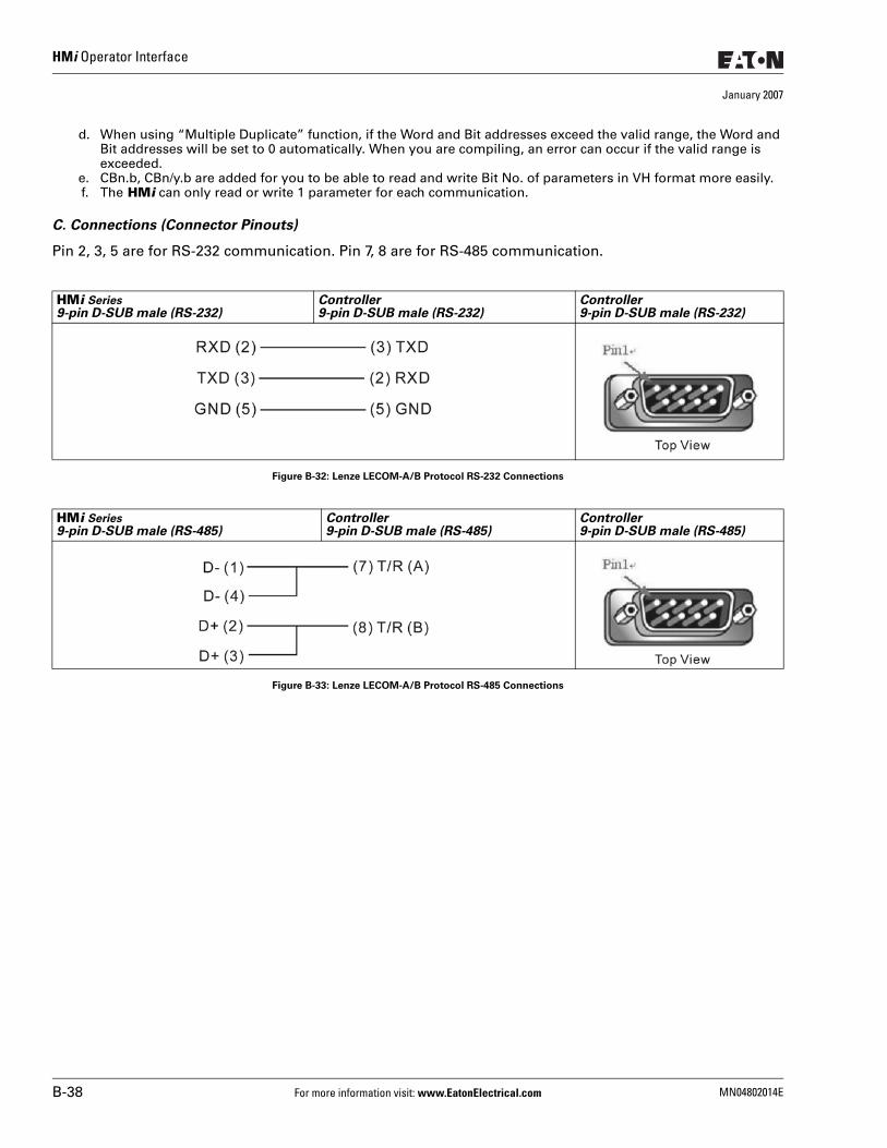
HMi Operator Interface
January 2007
d. When using “Multiple Duplicate” function, if the Word and Bit addresses exceed the valid range, the Word and Bit addresses will be set to 0 automatically. When you are compiling, an error can occur if the valid range is exceeded.
e. CBn.b, CBn/y.b are added for you to be able to read and write Bit No. of parameters in VH format more easily.f. The HMi can only read or write 1 parameter for each communication.
C. Connections (Connector Pinouts)
Pin 2, 3, 5 are for RS-232 communication. Pin 7, 8 are for RS-485 communication.
Figure B-32: Lenze LECOM-A/B Protocol RS-232 Connections
Figure B-33: Lenze LECOM-A/B Protocol RS-485 Connections
HMi Series9-pin D-SUB male (RS-232)
Controller9-pin D-SUB male (RS-232)
Controller9-pin D-SUB male (RS-232)
HMi Series9-pin D-SUB male (RS-485)
Controller9-pin D-SUB male (RS-485)
Controller9-pin D-SUB male (RS-485)
B-38 For more information visit: www.EatonElectrical.com MN04802014E
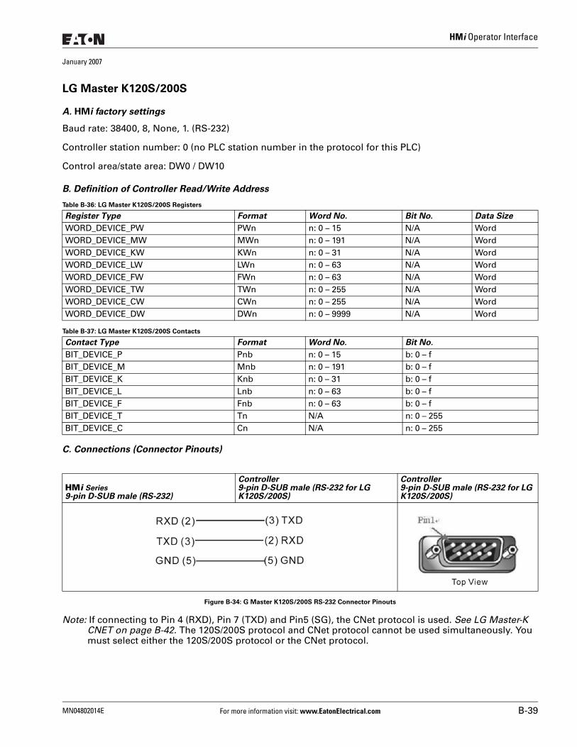
HMi Operator Interface
January 2007
LG Master K120S/200S
A. HMi factory settings
Baud rate: 38400, 8, None, 1. (RS-232)
Controller station number: 0 (no PLC station number in the protocol for this PLC)
Control area/state area: DW0 / DW10
B. Definition of Controller Read/Write Address
Table B-36: LG Master K120S/200S Registers
Table B-37: LG Master K120S/200S Contacts
C. Connections (Connector Pinouts)
Figure B-34: G Master K120S/200S RS-232 Connector Pinouts
Note: If connecting to Pin 4 (RXD), Pin 7 (TXD) and Pin5 (SG), the CNet protocol is used. See LG Master-K CNET on page B-42. The 120S/200S protocol and CNet protocol cannot be used simultaneously. You must select either the 120S/200S protocol or the CNet protocol.
Register Type Format Word No. Bit No. Data Size
WORD_DEVICE_PW PWn n: 0 – 15 N/A WordWORD_DEVICE_MW MWn n: 0 – 191 N/A WordWORD_DEVICE_KW KWn n: 0 – 31 N/A WordWORD_DEVICE_LW LWn n: 0 – 63 N/A WordWORD_DEVICE_FW FWn n: 0 – 63 N/A WordWORD_DEVICE_TW TWn n: 0 – 255 N/A WordWORD_DEVICE_CW CWn n: 0 – 255 N/A WordWORD_DEVICE_DW DWn n: 0 – 9999 N/A Word
Contact Type Format Word No. Bit No.
BIT_DEVICE_P Pnb n: 0 – 15 b: 0 – fBIT_DEVICE_M Mnb n: 0 – 191 b: 0 – fBIT_DEVICE_K Knb n: 0 – 31 b: 0 – fBIT_DEVICE_L Lnb n: 0 – 63 b: 0 – fBIT_DEVICE_F Fnb n: 0 – 63 b: 0 – fBIT_DEVICE_T Tn N/A n: 0 – 255BIT_DEVICE_C Cn N/A n: 0 – 255
HMi Series9-pin D-SUB male (RS-232)
Controller 9-pin D-SUB male (RS-232 for LG K120S/200S)
Controller 9-pin D-SUB male (RS-232 for LG K120S/200S)
MN04802014E For more information visit: www.EatonElectrical.com B-39
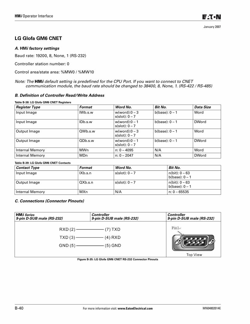
HMi Operator Interface
January 2007
LG Glofa GM6 CNET
A. HMi factory settings
Baud rate: 19200, 8, None, 1 (RS-232)
Controller station number: 0
Control area/state area: %MW0 / %MW10
Note: The HMi default setting is predefined for the CPU Port. If you want to connect to CNET communication module, the baud rate should be changed to 38400, 8, None, 1. (RS-422 / RS-485)
B. Definition of Controller Read/Write Address
Table B-38: LG Glofa GM6 CNET Registers
Table B-39: LG Glofa GM6 CNET Contacts
C. Connections (Connector Pinouts)
Figure B-35: LG Glofa GM6 CNET RS-232 Connector Pinouts
Register Type Format Word No. Bit No. Data Size
Input Image IWb.s.w w(word):0 – 3s(slot): 0 – 7
b(base): 0 – 1 Word
Input Image IDb.s.w w(word):0 – 1s(slot): 0 – 7
b(base): 0 – 1 DWord
Output Image QWb.s.w w(word):0 – 3s(slot): 0 – 7
b(base): 0 – 1 Word
Output Image QDb.s.w w(word):0 – 1s(slot): 0 – 7
b(base): 0 – 1 DWord
Internal Memory MWn n: 0 – 4095 N/A WordInternal Memory MDn n: 0 – 2047 N/A DWord
Contact Type Format Word No. Bit No.
Input Image IXb.s.n s(slot): 0 – 7 n(bit): 0 – 63b(base): 0 – 1
Output Image QXb.s.n s(slot): 0 – 7 n(bit): 0 – 63b(base): 0 – 1
Internal Memory MXn N/A n: 0 – 65535
HMi Series9-pin D-SUB male (RS-232)
Controller9-pin D-SUB male (RS-232)
Controller9-pin D-SUB male (RS-232)
B-40 For more information visit: www.EatonElectrical.com MN04802014E
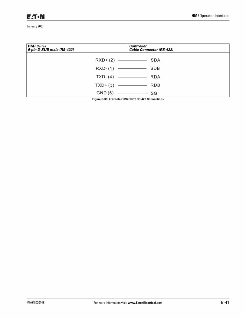
HMi Operator Interface
January 2007
Figure B-36: LG Glofa GM6 CNET RS-422 Connections
HMi Series9-pin D-SUB male (RS-422)
ControllerCable Connector (RS-422)
MN04802014E For more information visit: www.EatonElectrical.com B-41
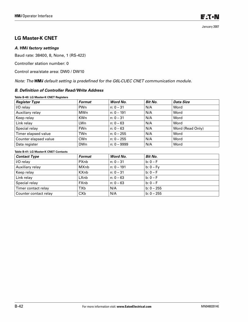
HMi Operator Interface
January 2007
LG Master-K CNET
A. HMi factory settings
Baud rate: 38400, 8, None, 1 (RS-422)
Controller station number: 0
Control area/state area: DW0 / DW10
Note: The HMi default setting is predefined for the G6L-CUEC CNET communication module.
B. Definition of Controller Read/Write Address
Table B-40: LG Master-K CNET Registers
Table B-41: LG Master-K CNET Contacts
Register Type Format Word No. Bit No. Data Size
I/O relay PWn n: 0 – 31 N/A WordAuxiliary relay MWn n: 0 – 191 N/A WordKeep relay KWn n: 0 – 31 N/A WordLink relay LWn n: 0 – 63 N/A WordSpecial relay FWn n: 0 – 63 N/A Word (Read Only)Timer elapsed value TWn n: 0 – 255 N/A WordCounter elapsed value CWn n: 0 – 255 N/A WordData register DWn n: 0 – 9999 N/A Word
Contact Type Format Word No. Bit No.
I/O relay PXnb n: 0 – 31 b: 0 – FAuxiliary relay MXnb n: 0 – 191 b: 0 – FyKeep relay KXnb n: 0 – 31 b: 0 – FLink relay LXnb n: 0 – 63 b: 0 – FSpecial relay FXnb n: 0 – 63 b: 0 – FTimer contact relay TXb N/A b: 0 – 255Counter contact relay CXb N/A b: 0 – 255
B-42 For more information visit: www.EatonElectrical.com MN04802014E
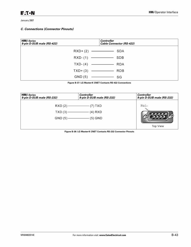
HMi Operator Interface
January 2007
C. Connections (Connector Pinouts)
Figure B-37: LG Master-K CNET Contacts RS-422 Connections
Figure B-38: LG Master-K CNET Contacts RS-232 Connector Pinouts
HMi Series9-pin D-SUB male (RS-422)
ControllerCable Connector (RS-422)
HMi Series9-pin D-SUB male (RS-232)
Controller9-pin D-SUB male (RS-232)
Controller9-pin D-SUB male (RS-232)
MN04802014E For more information visit: www.EatonElectrical.com B-43
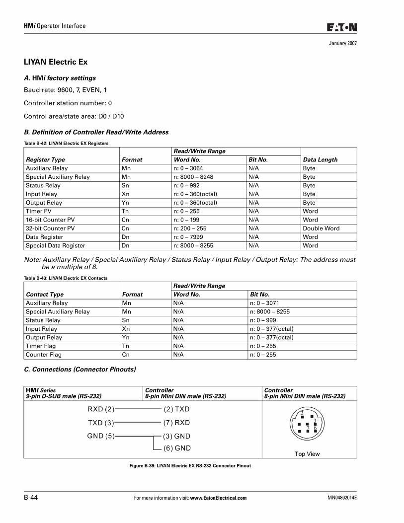
HMi Operator Interface
January 2007
LIYAN Electric Ex
A. HMi factory settings
Baud rate: 9600, 7, EVEN, 1
Controller station number: 0
Control area/state area: D0 / D10
B. Definition of Controller Read/Write Address
Table B-42: LIYAN Electric EX Registers
Note: Auxiliary Relay / Special Auxiliary Relay / Status Relay / Input Relay / Output Relay: The address must be a multiple of 8.
Table B-43: LIYAN Electric EX Contacts
C. Connections (Connector Pinouts)
Figure B-39: LIYAN Electric EX RS-232 Connector Pinout
Register Type Format
Read/Write Range
Data LengthWord No. Bit No.
Auxiliary Relay Mn n: 0 – 3064 N/A ByteSpecial Auxiliary Relay Mn n: 8000 – 8248 N/A ByteStatus Relay Sn n: 0 – 992 N/A ByteInput Relay Xn n: 0 – 360(octal) N/A ByteOutput Relay Yn n: 0 – 360(octal) N/A ByteTimer PV Tn n: 0 – 255 N/A Word16-bit Counter PV Cn n: 0 – 199 N/A Word32-bit Counter PV Cn n: 200 – 255 N/A Double WordData Register Dn n: 0 – 7999 N/A WordSpecial Data Register Dn n: 8000 – 8255 N/A Word
Contact Type Format
Read/Write Range
Word No. Bit No.
Auxiliary Relay Mn N/A n: 0 – 3071Special Auxiliary Relay Mn N/A n: 8000 – 8255Status Relay Sn N/A n: 0 – 999Input Relay Xn N/A n: 0 – 377(octal)Output Relay Yn N/A n: 0 – 377(octal)Timer Flag Tn N/A n: 0 – 255Counter Flag Cn N/A n: 0 – 255
HMi Series9-pin D-SUB male (RS-232)
Controller8-pin Mini DIN male (RS-232)
Controller8-pin Mini DIN male (RS-232)
B-44 For more information visit: www.EatonElectrical.com MN04802014E
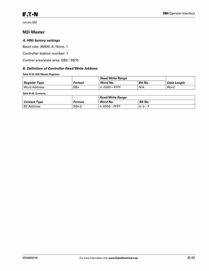
HMi Operator Interface
January 2007
M2i Master
A. HMi factory settings
Baud rate: 38400, 8, None, 1
Controller station number: 1
Control area/state area: SB0 / SB10
B. Definition of Controller Read/Write Address
Table B-44: M2i Master Registers
Table B-45: Contacts
Register Type Format
Read/Write Range
Data LengthWord No. Bit No.
Word Address SBn n: 0000 – FFFF N/A Word
Contact Type Format
Read/Write Range
Word No. Bit No.
Bit Address SBn.b n: 0000 – FFFF b: 0 – F
MN04802014E For more information visit: www.EatonElectrical.com B-45
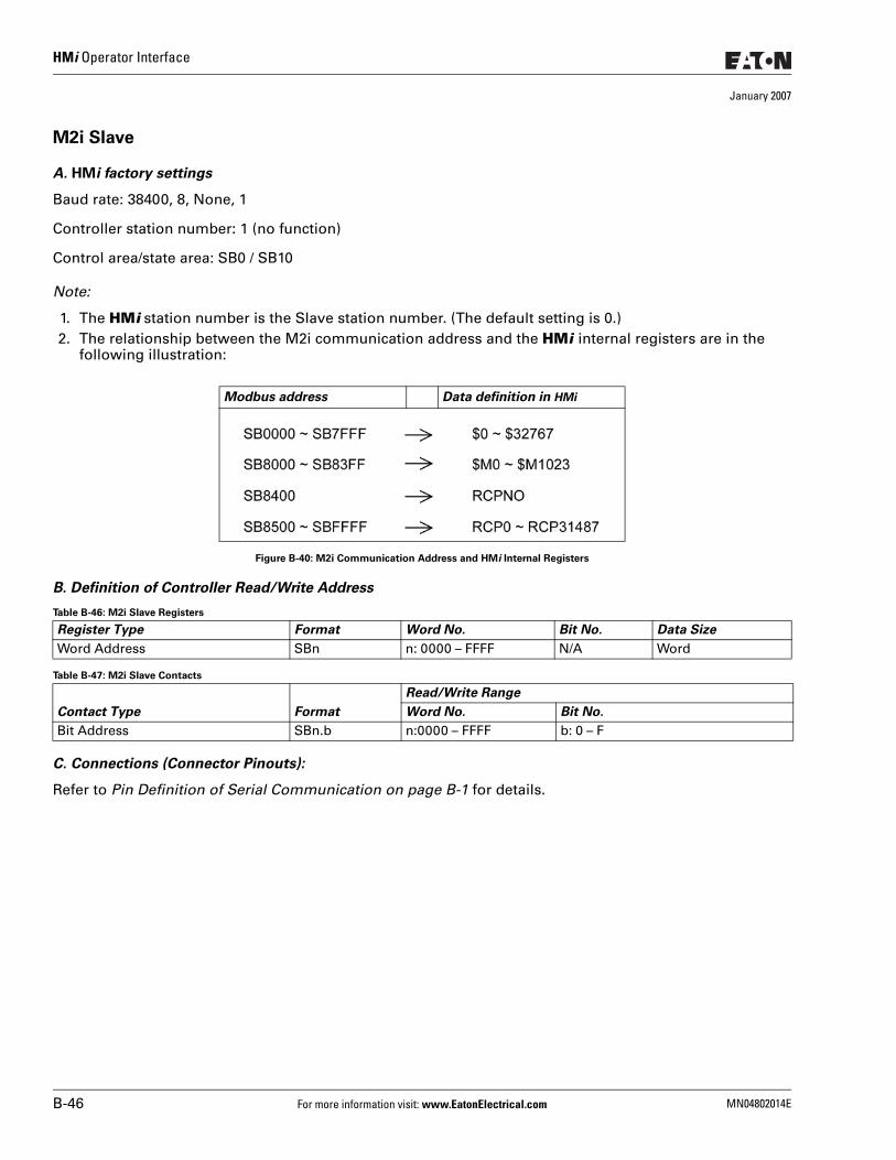
HMi Operator Interface
January 2007
M2i Slave
A. HMi factory settings
Baud rate: 38400, 8, None, 1
Controller station number: 1 (no function)
Control area/state area: SB0 / SB10
Note:
1. The HMi station number is the Slave station number. (The default setting is 0.)2. The relationship between the M2i communication address and the HMi internal registers are in the
following illustration:
Figure B-40: M2i Communication Address and HMi Internal Registers
B. Definition of Controller Read/Write Address
Table B-46: M2i Slave Registers
Table B-47: M2i Slave Contacts
C. Connections (Connector Pinouts):
Refer to Pin Definition of Serial Communication on page B-1 for details.
Modbus address Data definition in HMi
Register Type Format Word No. Bit No. Data Size
Word Address SBn n: 0000 – FFFF N/A Word
Contact Type Format
Read/Write Range
Word No. Bit No.
Bit Address SBn.b n:0000 – FFFF b: 0 – F
B-46 For more information visit: www.EatonElectrical.com MN04802014E
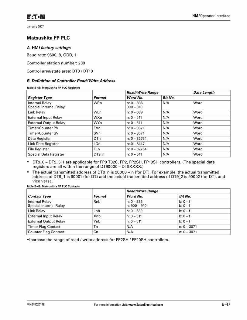
HMi Operator Interface
January 2007
Matsushita FP PLC
A. HMi factory settings
Baud rate: 9600, 8, ODD, 1
Controller station number: 238
Control area/state area: DT0 / DT10
B. Definition of Controller Read/Write Address
Table B-48: Matsushita FP PLC Registers
● DT9_0 – DT9_511 are applicable for FP0 T32C, FP2, FP2SH, FP10SH controllers. (The special data registers are all within the range of DT90000 – DT9XXXX.)
● The actual transmitted address of DT9_n is 90000 + n (for DT). For example, the actual transmitted address of DT9_1 is 90001 (for DT) and the actual transmitted address of DT9_2 is 90002 (for DT), and vice versa.
Table B-49: Matsushita FP PLC Contacts
● Increase the range of read / write address for FP2SH / FP10SH controllers.
Register Type Format
Read/Write Range Data Length
Word No. Bit No.
Internal RelaySpecial Internal Relay
WRn n: 0 – 886,900 – 910
N/A Word
Link Relay WLn n: 0 – 639 N/A WordExternal Input Relay WXn n: 0 – 511 N/A WordExternal Output Relay WYn n: 0 – 511 N/A WordTimer/Counter PV EVn n: 0 – 3071 N/A WordTimer/Counter SV SVn n: 0 – 3071 N/A WordData Register DTn n: 0 – 32764 N/A WordLink Data Register LDn n: 0 – 8447 N/A WordFile Register FLn n: 0 – 32764 N/A WordSpecial Data Register DT9_n n: 0 – 511 N/A Word
Contact Type Format
Read/Write Range
Word No. Bit No.
Internal RelaySpecial Internal Relay
Rnb n: 0 – 886n: 900 – 910
b: 0 – fb: 0 – f
Link Relay Lnb n: 0 – 639 b: 0 – fExternal Input Relay Xnb n: 0 – 511 b: 0 – fExternal Output Relay Ynb n: 0 – 511 b: 0 – fTimer Flag Contact Tn N/A n: 0 – 3071Counter Flag Contact Cn N/A n: 0 – 3071
MN04802014E For more information visit: www.EatonElectrical.com B-47
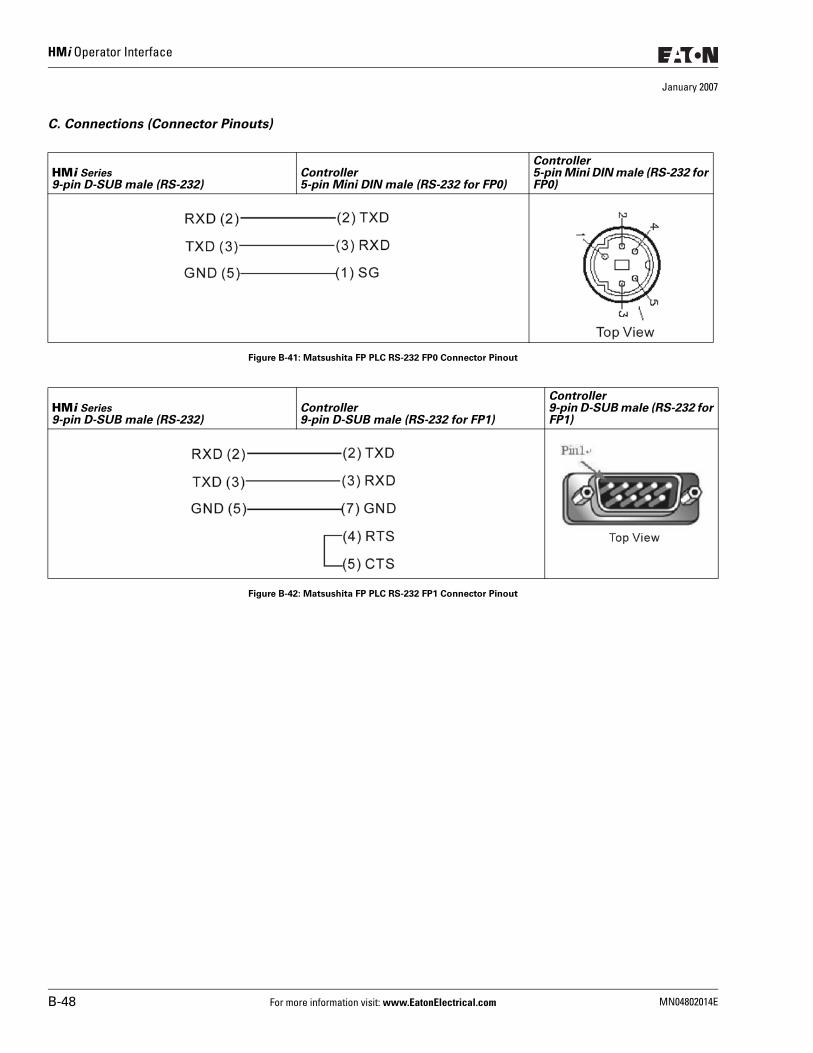
HMi Operator Interface
January 2007
C. Connections (Connector Pinouts)
Figure B-41: Matsushita FP PLC RS-232 FP0 Connector Pinout
Figure B-42: Matsushita FP PLC RS-232 FP1 Connector Pinout
HMi Series9-pin D-SUB male (RS-232)
Controller5-pin Mini DIN male (RS-232 for FP0)
Controller5-pin Mini DIN male (RS-232 for FP0)
HMi Series9-pin D-SUB male (RS-232)
Controller 9-pin D-SUB male (RS-232 for FP1)
Controller 9-pin D-SUB male (RS-232 for FP1)
B-48 For more information visit: www.EatonElectrical.com MN04802014E
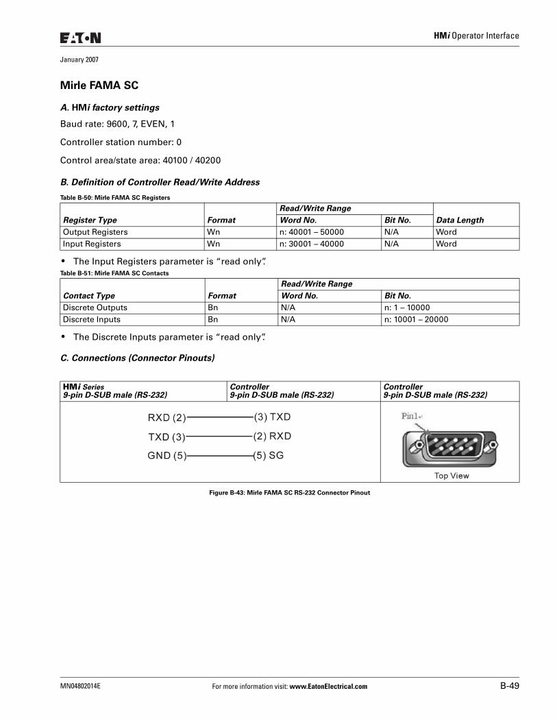
HMi Operator Interface
January 2007
Mirle FAMA SC
A. HMi factory settings
Baud rate: 9600, 7, EVEN, 1
Controller station number: 0
Control area/state area: 40100 / 40200
B. Definition of Controller Read/Write Address
Table B-50: Mirle FAMA SC Registers
● The Input Registers parameter is “read only”.Table B-51: Mirle FAMA SC Contacts
● The Discrete Inputs parameter is “read only”.
C. Connections (Connector Pinouts)
Figure B-43: Mirle FAMA SC RS-232 Connector Pinout
Register Type Format
Read/Write Range
Data LengthWord No. Bit No.
Output Registers Wn n: 40001 – 50000 N/A WordInput Registers Wn n: 30001 – 40000 N/A Word
Contact Type Format
Read/Write Range
Word No. Bit No.
Discrete Outputs Bn N/A n: 1 – 10000Discrete Inputs Bn N/A n: 10001 – 20000
HMi Series9-pin D-SUB male (RS-232)
Controller9-pin D-SUB male (RS-232)
Controller9-pin D-SUB male (RS-232)
MN04802014E For more information visit: www.EatonElectrical.com B-49
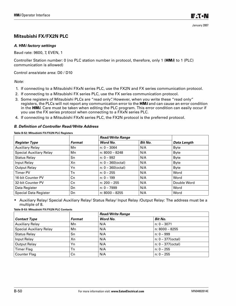
HMi Operator Interface
January 2007
Mitsubishi FX/FX2N PLC
A. HMi factory settings
Baud rate: 9600, 7, EVEN, 1
Controller Station number: 0 (no PLC station number in protocol, therefore, only 1 (HMi) to 1 (PLC) communication is allowed)
Control area/state area: D0 / D10
Note:
1. If connecting to a Mitsubishi FXxN series PLC, use the FX2N and FX series communication protocol.2. If connecting to a Mitsubishi FX series PLC, use the FX series communication protocol.3. Some registers of Mitsubishi PLCs are “read only”. However, when you write these “read only”
registers, the PLCs will not report any communication error to the HMi and can cause an error condition in the HMi. Care must be taken when editing the PLC program. This error condition can easily occur if you use the FX series protocol when connecting to a FXxN series PLC.
4. If connecting to a Mitsubishi FXxN series PLC, the FX2N protocol is the preferred protocol.
B. Definition of Controller Read/Write Address
Table B-52: Mitsubishi FX/FX2N PLC Registers
● Auxiliary Relay/ Special Auxiliary Relay/ Status Relay/ Input Relay /Output Relay: The address must be a multiple of 8.
Table B-53: Mitsubishi FX/FX2N PLC Contacts
Register Type Format
Read/Write Range
Data LengthWord No. Bit No.
Auxiliary Relay Mn n: 0 – 3064 N/A ByteSpecial Auxiliary Relay Mn n: 8000 – 8248 N/A ByteStatus Relay Sn n: 0 – 992 N/A ByteInput Relay Xn n: 0 – 360(octal) N/A ByteOutput Relay Yn n: 0 – 360(octal) N/A ByteTimer PV Tn n: 0 – 255 N/A Word16-bit Counter PV Cn n: 0 – 199 N/A Word32-bit Counter PV Cn n: 200 – 255 N/A Double WordData Register Dn n: 0 – 7999 N/A WordSpecial Data Register Dn n: 8000 – 8255 N/A Word
Contact Type Format
Read/Write Range
Word No. Bit No.
Auxiliary Relay Mn N/A n: 0 – 3071Special Auxiliary Relay Mn N/A n: 8000 – 8255Status Relay Sn N/A n: 0 – 999Input Relay Xn N/A n: 0 – 377(octal)Output Relay Yn N/A n: 0 – 377(octal)Timer Flag Tn N/A n: 0 – 255Counter Flag Cn N/A n: 0 – 255
B-50 For more information visit: www.EatonElectrical.com MN04802014E
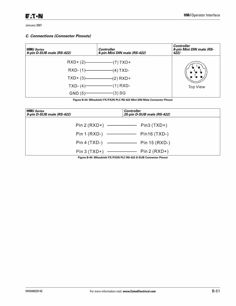
HMi Operator Interface
January 2007
C. Connections (Connector Pinouts)
Figure B-44: Mitsubishi FX/FX2N PLC RS-422 Mini DIN Male Connector Pinout
Figure B-45: Mitsubishi FX/FX2N PLC RS-422 D-SUB Connector Pinout
HMi Series9-pin D-SUB male (RS-422)
Controller8-pin Mini DIN male (RS-422)
Controller8-pin Mini DIN male (RS-422)
HMi Series9-pin D-SUB male (RS-422)
Controller25-pin D-SUB male (RS-422)
MN04802014E For more information visit: www.EatonElectrical.com B-51
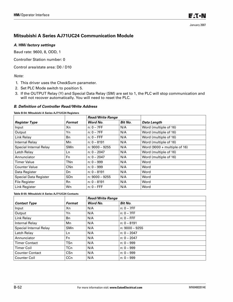
HMi Operator Interface
January 2007
Mitsubishi A Series AJ71UC24 Communication Module
A. HMi factory settings
Baud rate: 9600, 8, ODD, 1
Controller Station number: 0
Control area/state area: D0 / D10
Note:
1. This driver uses the CheckSum parameter.2. Set PLC Mode switch to position 5.3. If the OUTPUT Relay (Y) and Special Data Relay (SM) are set to 1, the PLC will stop communication and
will not recover automatically. You will need to reset the PLC.
B. Definition of Controller Read/Write Address
Table B-54: Mitsubishi A Series AJ71UC24 Registers
Table B-55: Mitsubishi A Series AJ71UC24 Contacts
Register Type Format
Read/Write Range
Data LengthWord No. Bit No.
Input Xn n: 0 – 7FF N/A Word (multiple of 16)Output Yn n: 0 – 7FF N/A Word (multiple of 16)Link Relay Bn n: 0 – FFF N/A Word (multiple of 16)Internal Relay Mn n: 0 – 8191 N/A Word (multiple of 16)Special Internal Relay SMn n: 9000 – 9255 N/A Word (9000 + multiple of 16)Latch Relay Ln n: 0 – 2047 N/A Word (multiple of 16)Annunciator Fn n: 0 – 2047 N/A Word (multiple of 16)Timer Value TNn n: 0 – 999 N/A WordCounter Value CNn n: 0 – 999 N/A WordData Register Dn n: 0 – 8191 N/A WordSpecial Data Register SDn n: 9000 – 9255 N/A WordFile Register Rn n: 0 – 8191 N/A WordLink Register Wn n: 0 – FFF N/A Word
Contact Type Format
Read/Write Range
Word No. Bit No.
Input Xn N/A n: 0 – 7FFOutput Yn N/A n: 0 – 7FFLink Relay Bn N/A n: 0 – FFFInternal Relay Mn N/A n: 0 – 8191Special Internal Relay SMn N/A n: 9000 – 9255Latch Relay Ln N/A n: 0 – 2047Annunciator Fn N/A n: 0 – 2047Timer Contact TSn N/A n: 0 – 999Timer Coil TCn N/A n: 0 – 999Counter Contact CSn N/A n: 0 – 999Counter Coil CCn N/A n: 0 – 999
B-52 For more information visit: www.EatonElectrical.com MN04802014E
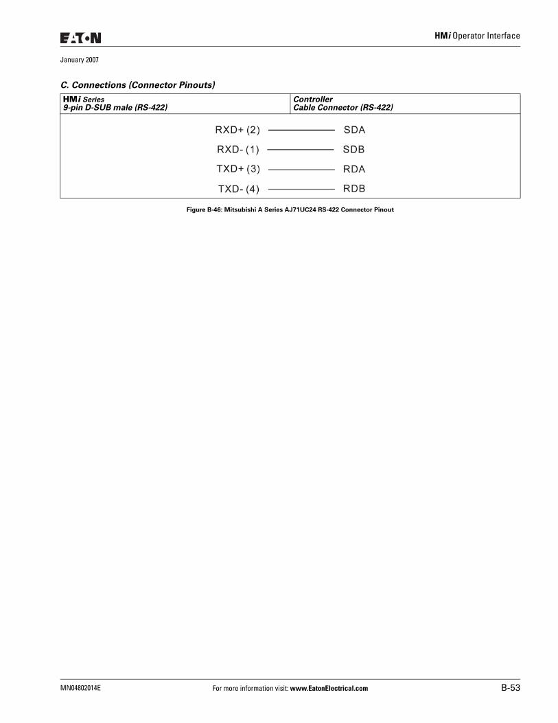
HMi Operator Interface
January 2007
C. Connections (Connector Pinouts)
Figure B-46: Mitsubishi A Series AJ71UC24 RS-422 Connector Pinout
HMi Series9-pin D-SUB male (RS-422)
ControllerCable Connector (RS-422)
MN04802014E For more information visit: www.EatonElectrical.com B-53
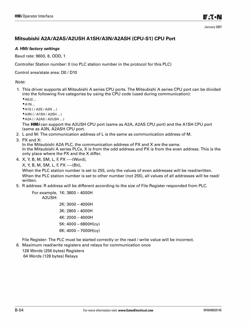
HMi Operator Interface
January 2007
Mitsubishi A2A/A2AS/A2USH A1SH/A3N/A2ASH (CPU-S1) CPU Port
A. HMi factory settings
Baud rate: 9600, 8, ODD, 1
Controller Station number: 0 (no PLC station number in the protocol for this PLC)
Control area/state area: D0 / D10
Note:
1. This driver supports all Mitsubishi A series CPU ports. The Mitsubishi A series CPU port can be divided into the following five categories by using the CPU code (used during communication): ● A0J2… ● A1N… ● A1S ( / A2S / A2N …) ● A3N ( / A1SH / A2SH …) ● A2A ( / A2AS / A2USH …)
The HMi can support the A2USH CPU port (same as A2A, A2AS CPU port) and the A1SH CPU port (same as A3N, A2ASH CPU port.
2. L and M: The communication address of L is the same as communication address of M.3. PX and X:
In the Mitsubishi A2A PLC, the communication address of PX and X are the same.In the Mitsubishi A series PLCs, X is from the odd address and PX is from the even address. This is the only place where the PX and the X differ.
4. X, Y, B, M, SM, L, F, PX ----(Word),X, Y, B, M, SM, L, F, PX ----(Bit),When the PLC station number is set to 255, only the values of even addresses will be read/written.When the PLC station number is set to other number (not 255), all values of all addresses will be read/written.
5. R address: R address will be different according to the size of File Register responded from PLC.
File Register: The PLC must be started correctly or the read / write value will be incorrect.6. Maximum read/write registers and relays for communication once
128 Words (256 bytes) Registers 64 Words (128 bytes) Relays
For example,A2USH:
1K: 3800 – 4000H
2K: 3000 – 4000H
3K: 2800 – 4000H
4K: 2000 – 4000H
5K: 4000 – 6800H(cy)
6K: 4000 – 7000H(cy)
B-54 For more information visit: www.EatonElectrical.com MN04802014E
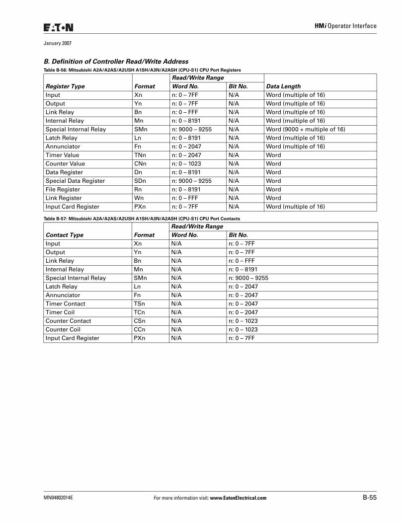
HMi Operator Interface
January 2007
B. Definition of Controller Read/Write Address
Table B-56: Mitsubishi A2A/A2AS/A2USH A1SH/A3N/A2ASH (CPU-S1) CPU Port Registers
Table B-57: Mitsubishi A2A/A2AS/A2USH A1SH/A3N/A2ASH (CPU-S1) CPU Port Contacts
Register Type Format
Read/Write Range
Data LengthWord No. Bit No.
Input Xn n: 0 – 7FF N/A Word (multiple of 16)Output Yn n: 0 – 7FF N/A Word (multiple of 16)Link Relay Bn n: 0 – FFF N/A Word (multiple of 16)Internal Relay Mn n: 0 – 8191 N/A Word (multiple of 16)Special Internal Relay SMn n: 9000 – 9255 N/A Word (9000 + multiple of 16)Latch Relay Ln n: 0 – 8191 N/A Word (multiple of 16)Annunciator Fn n: 0 – 2047 N/A Word (multiple of 16)Timer Value TNn n: 0 – 2047 N/A WordCounter Value CNn n: 0 – 1023 N/A WordData Register Dn n: 0 – 8191 N/A WordSpecial Data Register SDn n: 9000 – 9255 N/A WordFile Register Rn n: 0 – 8191 N/A WordLink Register Wn n: 0 – FFF N/A WordInput Card Register PXn n: 0 – 7FF N/A Word (multiple of 16)
Contact Type Format
Read/Write Range
Word No. Bit No.
Input Xn N/A n: 0 – 7FFOutput Yn N/A n: 0 – 7FFLink Relay Bn N/A n: 0 – FFFInternal Relay Mn N/A n: 0 – 8191Special Internal Relay SMn N/A n: 9000 – 9255Latch Relay Ln N/A n: 0 – 2047Annunciator Fn N/A n: 0 – 2047Timer Contact TSn N/A n: 0 – 2047Timer Coil TCn N/A n: 0 – 2047Counter Contact CSn N/A n: 0 – 1023Counter Coil CCn N/A n: 0 – 1023Input Card Register PXn N/A n: 0 – 7FF
MN04802014E For more information visit: www.EatonElectrical.com B-55
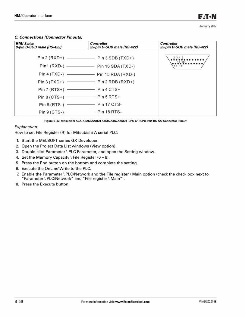
HMi Operator Interface
January 2007
C. Connections (Connector Pinouts)
Figure B-47: Mitsubishi A2A/A2AS/A2USH A1SH/A3N/A2ASH (CPU-S1) CPU Port RS-422 Connector Pinout
Explanation:How to set File Register (R) for Mitsubishi A serial PLC:
1. Start the MELSOFT series GX Developer.2. Open the Project Data List windows (View option).3. Double-click Parameter \ PLC Parameter, and open the Setting window.4. Set the Memory Capacity \ File Register (0 – 8).5. Press the End button on the bottom and complete the setting.6. Execute the OnLine\Write to the PLC.7. Enable the Parameter \ PLC/Network and the File register \ Main option (check the check box next to
“Parameter \ PLC/Network” and “File register \ Main”).8. Press the Execute button.
HMi Series9-pin D-SUB male (RS-422)
Controller25-pin D-SUB male (RS-422)
Controller25-pin D-SUB male (RS-422)
B-56 For more information visit: www.EatonElectrical.com MN04802014E
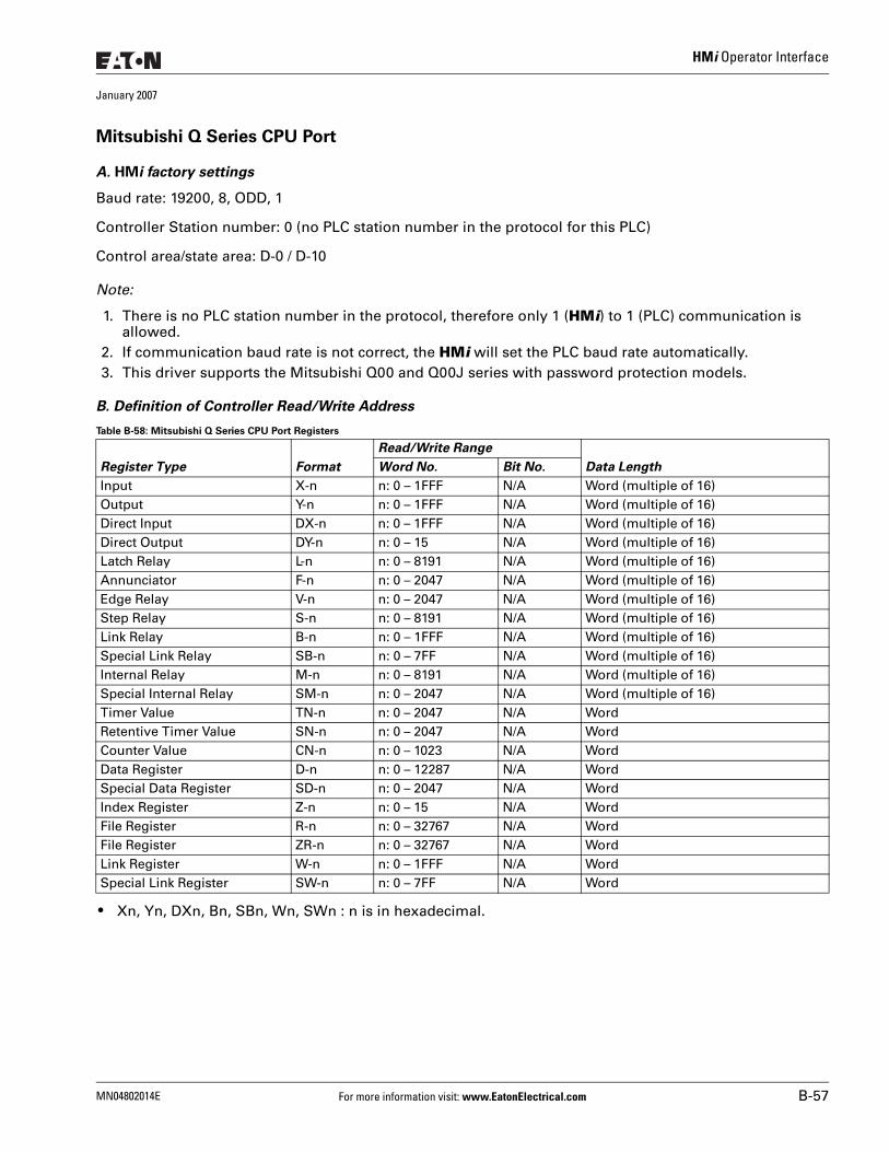
HMi Operator Interface
January 2007
Mitsubishi Q Series CPU Port
A. HMi factory settings
Baud rate: 19200, 8, ODD, 1
Controller Station number: 0 (no PLC station number in the protocol for this PLC)
Control area/state area: D-0 / D-10
Note:
1. There is no PLC station number in the protocol, therefore only 1 (HMi) to 1 (PLC) communication is allowed.
2. If communication baud rate is not correct, the HMi will set the PLC baud rate automatically.3. This driver supports the Mitsubishi Q00 and Q00J series with password protection models.
B. Definition of Controller Read/Write Address
Table B-58: Mitsubishi Q Series CPU Port Registers
● Xn, Yn, DXn, Bn, SBn, Wn, SWn : n is in hexadecimal.
Register Type Format
Read/Write Range
Data LengthWord No. Bit No.
Input X-n n: 0 – 1FFF N/A Word (multiple of 16)Output Y-n n: 0 – 1FFF N/A Word (multiple of 16)Direct Input DX-n n: 0 – 1FFF N/A Word (multiple of 16)Direct Output DY-n n: 0 – 15 N/A Word (multiple of 16)Latch Relay L-n n: 0 – 8191 N/A Word (multiple of 16)Annunciator F-n n: 0 – 2047 N/A Word (multiple of 16)Edge Relay V-n n: 0 – 2047 N/A Word (multiple of 16)Step Relay S-n n: 0 – 8191 N/A Word (multiple of 16)Link Relay B-n n: 0 – 1FFF N/A Word (multiple of 16)Special Link Relay SB-n n: 0 – 7FF N/A Word (multiple of 16)Internal Relay M-n n: 0 – 8191 N/A Word (multiple of 16)Special Internal Relay SM-n n: 0 – 2047 N/A Word (multiple of 16)Timer Value TN-n n: 0 – 2047 N/A WordRetentive Timer Value SN-n n: 0 – 2047 N/A WordCounter Value CN-n n: 0 – 1023 N/A WordData Register D-n n: 0 – 12287 N/A WordSpecial Data Register SD-n n: 0 – 2047 N/A WordIndex Register Z-n n: 0 – 15 N/A WordFile Register R-n n: 0 – 32767 N/A WordFile Register ZR-n n: 0 – 32767 N/A WordLink Register W-n n: 0 – 1FFF N/A WordSpecial Link Register SW-n n: 0 – 7FF N/A Word
MN04802014E For more information visit: www.EatonElectrical.com B-57
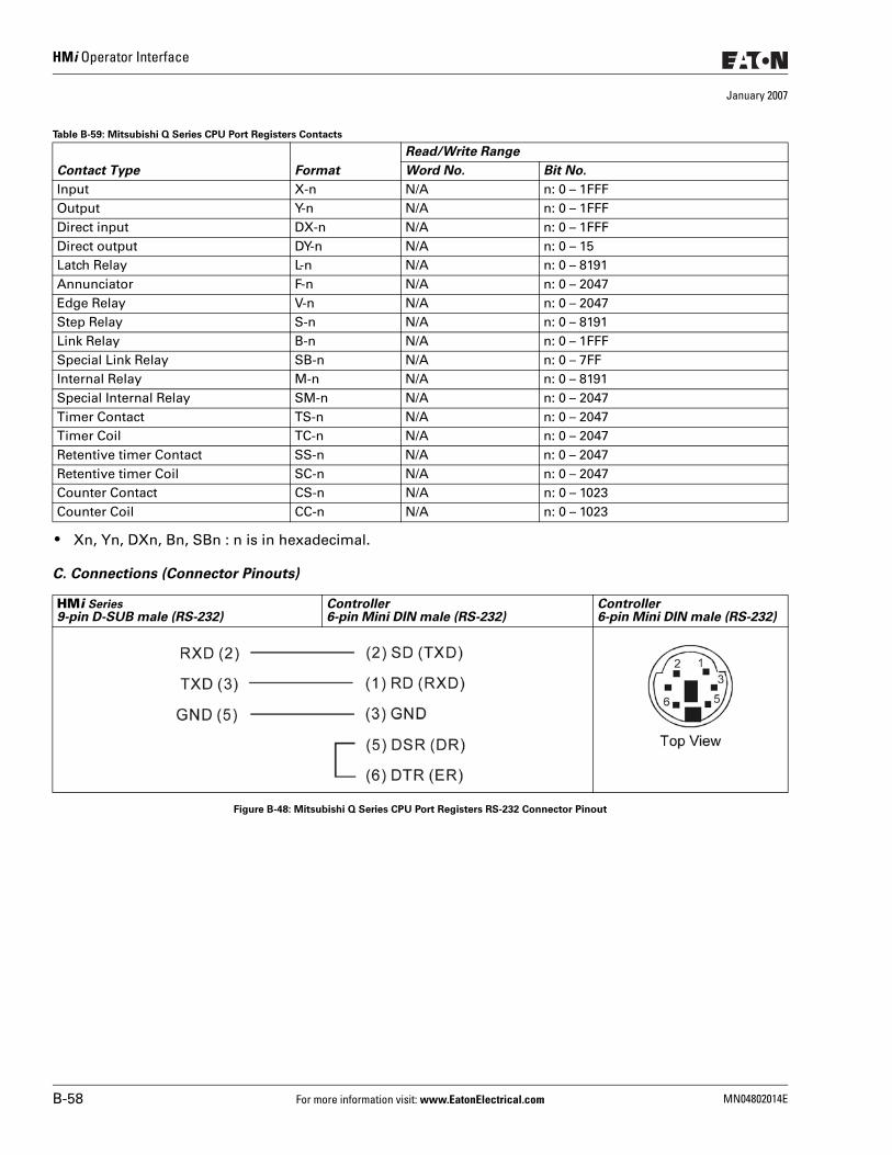
HMi Operator Interface
January 2007
Table B-59: Mitsubishi Q Series CPU Port Registers Contacts
● Xn, Yn, DXn, Bn, SBn : n is in hexadecimal.
C. Connections (Connector Pinouts)
Figure B-48: Mitsubishi Q Series CPU Port Registers RS-232 Connector Pinout
Contact Type Format
Read/Write Range
Word No. Bit No.
Input X-n N/A n: 0 – 1FFFOutput Y-n N/A n: 0 – 1FFFDirect input DX-n N/A n: 0 – 1FFFDirect output DY-n N/A n: 0 – 15Latch Relay L-n N/A n: 0 – 8191Annunciator F-n N/A n: 0 – 2047Edge Relay V-n N/A n: 0 – 2047Step Relay S-n N/A n: 0 – 8191Link Relay B-n N/A n: 0 – 1FFFSpecial Link Relay SB-n N/A n: 0 – 7FFInternal Relay M-n N/A n: 0 – 8191Special Internal Relay SM-n N/A n: 0 – 2047Timer Contact TS-n N/A n: 0 – 2047Timer Coil TC-n N/A n: 0 – 2047Retentive timer Contact SS-n N/A n: 0 – 2047Retentive timer Coil SC-n N/A n: 0 – 2047Counter Contact CS-n N/A n: 0 – 1023Counter Coil CC-n N/A n: 0 – 1023
HMi Series9-pin D-SUB male (RS-232)
Controller6-pin Mini DIN male (RS-232)
Controller6-pin Mini DIN male (RS-232)
B-58 For more information visit: www.EatonElectrical.com MN04802014E
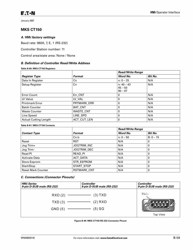
HMi Operator Interface
January 2007
MKS CT150
A. HMi factory settings
Baud rate: 9600, 7, E, 1 (RS-232)
Controller Station number: 11
Control area/state area: None / None
B. Definition of Controller Read/Write Address
Table B-60: MKS CT150 Registers
Table B-61: MKS CT150 Contacts
C. Connections (Connector Pinouts)
Figure B-49: MKS CT150 RS-232 Connector Pinout
Register Type Format
Read/Write Range
Word No. Bit No.
Data In Register Cn n: 0 – 25 N/ASetup Register Cn n: 40 – 43
45 – 5090 – 97
N/A
Error Count Err_CNT 0 N/ALV Value LV_VAL 0 N/APrintmark Error PRTMARK_ERR 0 N/ABatch Counter BAT_CNT 0 N/AWaste Counter WASTE_CNT 0 N/ALine Speed LINE_SPD 0 N/AActual Cutting Length ACT_CUT_LEN 0 N/A
Contact Type Format
Read/Write Range
Word No. Bit No.
Cn.b n: 0 – 50 B: 0 – 15Reset RST N/A 0Jog Trim+ JOGTRIM_INC N/A 0Jog Trim- JOGTRIM_DEC N/A 0Read PI READ_PI N/A 0Activate Data ACT_DATA N/A 0Store Eeprom STR_EEPROM N/A 0Start/Stop START_STOP N/A 0Reset Mark Counter RSTMARK_CNT N/A 0
HMi Series9-pin D-SUB male (RS-232)
Controller9-pin D-SUB male (RS-232)
Controller9-pin D-SUB male (RS-232)
MN04802014E For more information visit: www.EatonElectrical.com B-59
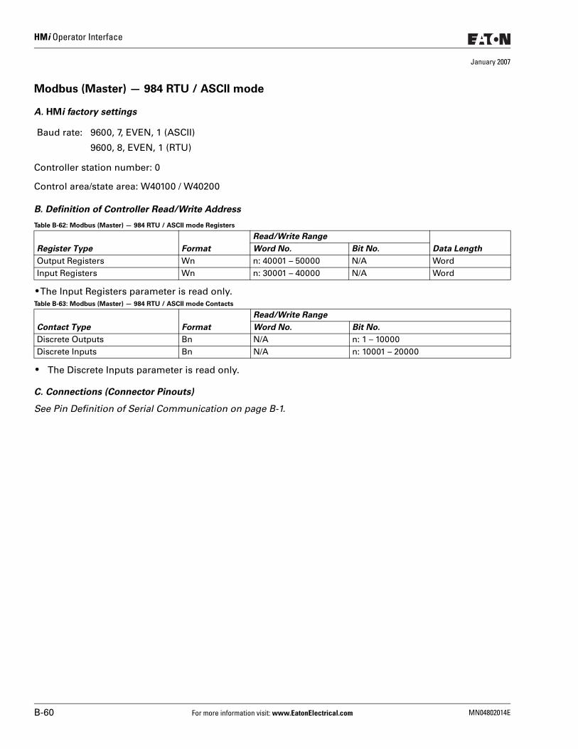
HMi Operator Interface
January 2007
Modbus (Master) — 984 RTU / ASCII mode
A. HMi factory settings
Controller station number: 0
Control area/state area: W40100 / W40200
B. Definition of Controller Read/Write Address
Table B-62: Modbus (Master) — 984 RTU / ASCII mode Registers
● The Input Registers parameter is read only.Table B-63: Modbus (Master) — 984 RTU / ASCII mode Contacts
● The Discrete Inputs parameter is read only.
C. Connections (Connector Pinouts)
See Pin Definition of Serial Communication on page B-1.
Baud rate: 9600, 7, EVEN, 1 (ASCII)
9600, 8, EVEN, 1 (RTU)
Register Type Format
Read/Write Range
Data LengthWord No. Bit No.
Output Registers Wn n: 40001 – 50000 N/A WordInput Registers Wn n: 30001 – 40000 N/A Word
Contact Type Format
Read/Write Range
Word No. Bit No.
Discrete Outputs Bn N/A n: 1 – 10000Discrete Inputs Bn N/A n: 10001 – 20000
B-60 For more information visit: www.EatonElectrical.com MN04802014E
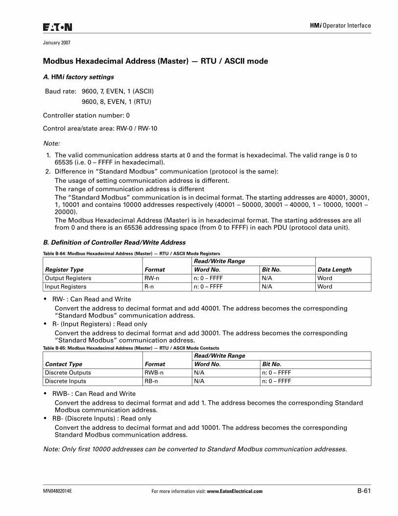
HMi Operator Interface
January 2007
Modbus Hexadecimal Address (Master) — RTU / ASCII mode
A. HMi factory settings
Controller station number: 0
Control area/state area: RW-0 / RW-10
Note:
1. The valid communication address starts at 0 and the format is hexadecimal. The valid range is 0 to 65535 (i.e. 0 – FFFF in hexadecimal).
2. Difference in “Standard Modbus” communication (protocol is the same):The usage of setting communication address is different.The range of communication address is differentThe “Standard Modbus” communication is in decimal format. The starting addresses are 40001, 30001, 1, 10001 and contains 10000 addresses respectively (40001 – 50000, 30001 – 40000, 1 – 10000, 10001 – 20000).The Modbus Hexadecimal Address (Master) is in hexadecimal format. The starting addresses are all from 0 and there is an 65536 addressing space (from 0 to FFFF) in each PDU (protocol data unit).
B. Definition of Controller Read/Write Address
Table B-64: Modbus Hexadecimal Address (Master) — RTU / ASCII Mode Registers
● RW- : Can Read and WriteConvert the address to decimal format and add 40001. The address becomes the corresponding “Standard Modbus” communication address.
● R- (Input Registers) : Read onlyConvert the address to decimal format and add 30001. The address becomes the corresponding “Standard Modbus” communication address.
Table B-65: Modbus Hexadecimal Address (Master) — RTU / ASCII Mode Contacts
● RWB- : Can Read and Write Convert the address to decimal format and add 1. The address becomes the corresponding Standard Modbus communication address.
● RB- (Discrete Inputs) : Read only Convert the address to decimal format and add 10001. The address becomes the corresponding Standard Modbus communication address.
Note: Only first 10000 addresses can be converted to Standard Modbus communication addresses.
Baud rate: 9600, 7, EVEN, 1 (ASCII)
9600, 8, EVEN, 1 (RTU)
Register Type Format
Read/Write Range
Data LengthWord No. Bit No.
Output Registers RW-n n: 0 – FFFF N/A WordInput Registers R-n n: 0 – FFFF N/A Word
Contact Type Format
Read/Write Range
Word No. Bit No.
Discrete Outputs RWB-n N/A n: 0 – FFFFDiscrete Inputs RB-n N/A n: 0 – FFFF
MN04802014E For more information visit: www.EatonElectrical.com B-61
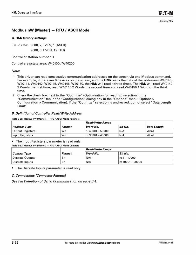
HMi Operator Interface
January 2007
Modbus nW (Master) — RTU / ASCII Mode
A. HMi factory settings
Controller station number: 1
Control area/state area: W40100 / W40200
Note:
1. This driver can read consecutive communication addresses on the screen via one Modbus command. For example, if there are 6 devices on the screen, and the HMi reads the data of the addresses W40140, W40141, W40142, W40145, W40146, W40150, the HMi will read it three times. The HMi will read W40140 3 Words the first time, read W40145 2 Words the second time and read W40150 1 Word on the third time.
2. Check the check box next to the “Optimize” (Optimization for reading) selection in the “Communication” tab in the “Configuration” dialog box in the “Options” menu (Options > Configuration > Communication). If the “Optimize” selection is unchecked, do not select “Data Length Limit”.
B. Definition of Controller Read/Write Address
Table B-66: Modbus nW (Master) — RTU / ASCII Mode Registers
● The Input Registers parameter is read only.Table B-67: Modbus nW (Master) — RTU / ASCII Mode Contacts
● The Discrete Inputs parameter is read only.
C. Connections (Connector Pinouts)
See Pin Definition of Serial Communication on page B-1.
Baud rate: 9600, 7, EVEN, 1 (ASCII)
9600, 8, EVEN, 1 (RTU)
Register Type Format
Read/Write Range
Data LengthWord No. Bit No.
Output Registers Wn n: 40001 – 50000 N/A WordInput Registers Wn n: 30001 – 40000 N/A Word
Contact Type Format
Read/Write Range
Word No. Bit No.
Discrete Outputs Bn N/A n: 1 – 10000Discrete Inputs Bn N/A n: 10001 – 20000
B-62 For more information visit: www.EatonElectrical.com MN04802014E
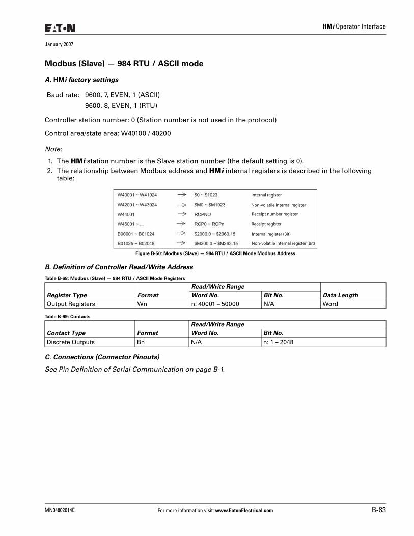
HMi Operator Interface
January 2007
Modbus (Slave) — 984 RTU / ASCII mode
A. HMi factory settings
Controller station number: 0 (Station number is not used in the protocol)
Control area/state area: W40100 / 40200
Note:
1. The HMi station number is the Slave station number (the default setting is 0).2. The relationship between Modbus address and HMi internal registers is described in the following
table:
Figure B-50: Modbus (Slave) — 984 RTU / ASCII Mode Modbus Address
B. Definition of Controller Read/Write Address
Table B-68: Modbus (Slave) — 984 RTU / ASCII Mode Registers
Table B-69: Contacts
C. Connections (Connector Pinouts)
See Pin Definition of Serial Communication on page B-1.
Baud rate: 9600, 7, EVEN, 1 (ASCII)
9600, 8, EVEN, 1 (RTU)
Register Type Format
Read/Write Range
Data LengthWord No. Bit No.
Output Registers Wn n: 40001 – 50000 N/A Word
Contact Type Format
Read/Write Range
Word No. Bit No.
Discrete Outputs Bn N/A n: 1 – 2048
Internal register
Non-volatile internal register
Receipt number register
Receipt register
Internal register (Bit)
Non-volatile internal register (Bit)
MN04802014E For more information visit: www.EatonElectrical.com B-63
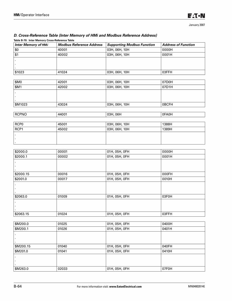
HMi Operator Interface
January 2007
D. Cross-Reference Table (Inter Memory of HMi and Modbus Reference Address)
Table B-70: Inter Memory Cross-Reference Table
Inter Memory of HMi Modbus Reference Address Supporting Modbus Function Address of Function
$0 40001 03H, 06H, 10H 0000H$1 40002 03H, 06H, 10H 0001H...$1023 41024 03H, 06H, 10H 03FFH
$M0 42001 03H, 06H, 10H 07D0H$M1 42002 03H, 06H, 10H 07D1H...$M1023 43024 03H, 06H, 10H 0BCFH
RCPNO 44001 03H, 06H 0FA0H
RCP0 45001 03H, 06H, 10H 1388HRCP1 45002 03H, 06H, 10H 1389H...
$2000.0 00001 01H, 05H, 0FH 0000H$2000.1 00002 01H, 05H, 0FH 0001H...$2000.15 00016 01H, 05H, 0FH 000FH$2001.0 00017 01H, 05H, 0FH 0010H...$2063.0 01009 01H, 05H, 0FH 03F0H...$2063.15 01024 01H, 05H, 0FH 03FFH
$M200.0 01025 01H, 05H, 0FH 0400H$M200.1 01026 01H, 05H, 0FH 0401H...$M200.15 01040 01H, 05H, 0FH 040FH$M201.0 01041 01H, 05H, 0FH 0410H...$M263.0 02033 01H, 05H, 0FH 07F0H
B-64 For more information visit: www.EatonElectrical.com MN04802014E
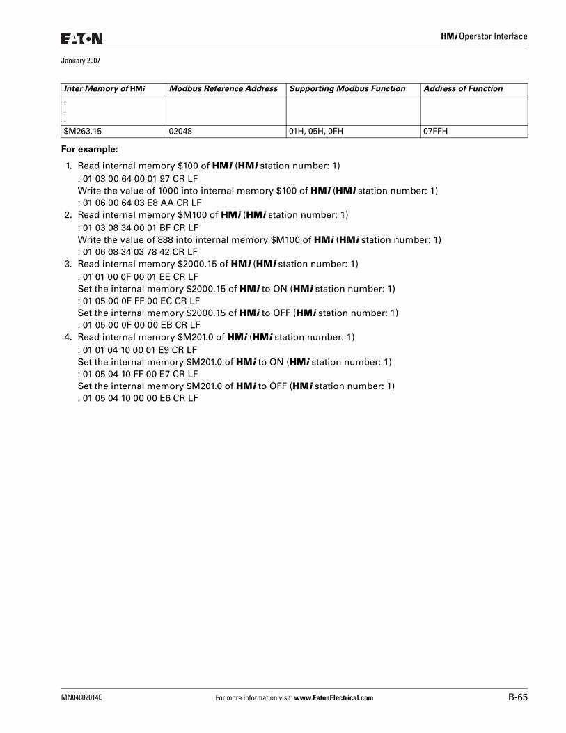
HMi Operator Interface
January 2007
For example:
1. Read internal memory $100 of HMi (HMi station number: 1): 01 03 00 64 00 01 97 CR LFWrite the value of 1000 into internal memory $100 of HMi (HMi station number: 1): 01 06 00 64 03 E8 AA CR LF
2. Read internal memory $M100 of HMi (HMi station number: 1): 01 03 08 34 00 01 BF CR LFWrite the value of 888 into internal memory $M100 of HMi (HMi station number: 1): 01 06 08 34 03 78 42 CR LF
3. Read internal memory $2000.15 of HMi (HMi station number: 1): 01 01 00 0F 00 01 EE CR LFSet the internal memory $2000.15 of HMi to ON (HMi station number: 1): 01 05 00 0F FF 00 EC CR LFSet the internal memory $2000.15 of HMi to OFF (HMi station number: 1): 01 05 00 0F 00 00 EB CR LF
4. Read internal memory $M201.0 of HMi (HMi station number: 1): 01 01 04 10 00 01 E9 CR LFSet the internal memory $M201.0 of HMi to ON (HMi station number: 1): 01 05 04 10 FF 00 E7 CR LFSet the internal memory $M201.0 of HMi to OFF (HMi station number: 1): 01 05 04 10 00 00 E6 CR LF
.
.
.$M263.15 02048 01H, 05H, 0FH 07FFH
Inter Memory of HMi Modbus Reference Address Supporting Modbus Function Address of Function
MN04802014E For more information visit: www.EatonElectrical.com B-65
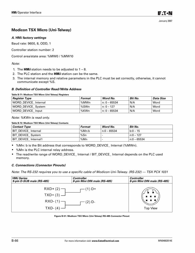
HMi Operator Interface
January 2007
Modicon TSX Micro (Uni-Telway)
A. HMi factory settings
Baud rate: 9600, 8, ODD, 1
Controller station number: 2
Control area/state area: %MW0 / %MW10
Note:
1. The HMi station needs to be adjusted to 1 – 8.2. The PLC station and the HMi station can be the same.3. The internal memory and relative parameters in the PLC must be set correctly, otherwise, it cannot
communicate except %S.
B. Definition of Controller Read/Write Address
Table B-71: Modicon TSX Micro (Uni-Telway) Registers
Note: %KWn is read only.
Table B-72: Modicon TSX Micro (Uni-Telway) Contacts
● %Mn: b is the Bit address that corresponds to WORD_DEVICE_ Internal (%MWn). ● %Mn is the PLC internal relay address. ● The read/write range of WORD_DEVICE_ Internal / BIT_DEVICE_ Internal depends on the PLC used
memory.
C. Connections (Connector Pinouts)
Note: The RS-232 requires you to use a specific cable of Modicon Uni-Telway. (RS-232) --- TSX PCX 1031
Figure B-51: Modicon TSX Micro (Uni-Telway) RS-485 Connector Pinout
Register Type Format Word No. Bit No. Data Size
WORD_DEVICE_ Internal %MWn n: 0 – 65534 N/A WordWORD_DEVICE_ System %SWn n: 0 – 127 N/A WordWORD_DEVICE_ Input %KWn n: 0 – 65534 N/A Word
Contact Type Format Word No. Bit No.
BIT_DEVICE_ Internal %Mn:b n:0 – 65534 b:0 – 15BIT_DEVICE_ System %Sn - n:0 – 127BIT_DEVICE_ Internal1 %Mn - n:0 – 65534
HMi Series9-pin D-SUB male (RS-485)
Controller8-pin Mini DIN male (RS-485)
Controller8-pin Mini DIN male (RS-485)
B-66 For more information visit: www.EatonElectrical.com MN04802014E

HMi Operator Interface
January 2007
Modicon TWIDO
Functions the same as Modbus (Master) --- 984 RTU on page B-60.
MN04802014E For more information visit: www.EatonElectrical.com B-67
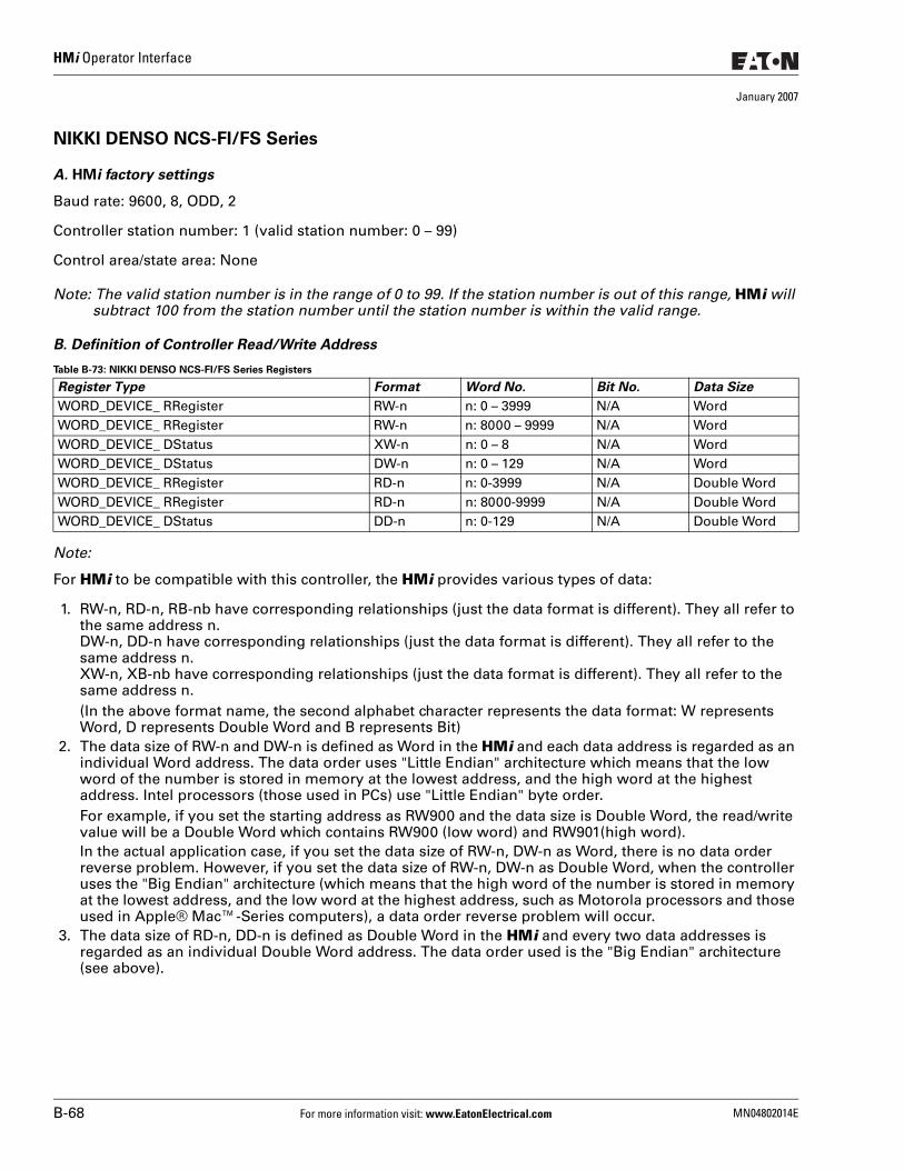
HMi Operator Interface
January 2007
NIKKI DENSO NCS-FI/FS Series
A. HMi factory settings
Baud rate: 9600, 8, ODD, 2
Controller station number: 1 (valid station number: 0 – 99)
Control area/state area: None
Note: The valid station number is in the range of 0 to 99. If the station number is out of this range, HMi will subtract 100 from the station number until the station number is within the valid range.
B. Definition of Controller Read/Write Address
Table B-73: NIKKI DENSO NCS-FI/FS Series Registers
Note:
For HMi to be compatible with this controller, the HMi provides various types of data:
1. RW-n, RD-n, RB-nb have corresponding relationships (just the data format is different). They all refer to the same address n. DW-n, DD-n have corresponding relationships (just the data format is different). They all refer to the same address n.XW-n, XB-nb have corresponding relationships (just the data format is different). They all refer to the same address n.(In the above format name, the second alphabet character represents the data format: W represents Word, D represents Double Word and B represents Bit)
2. The data size of RW-n and DW-n is defined as Word in the HMi and each data address is regarded as an individual Word address. The data order uses "Little Endian" architecture which means that the low word of the number is stored in memory at the lowest address, and the high word at the highest address. Intel processors (those used in PCs) use "Little Endian" byte order.For example, if you set the starting address as RW900 and the data size is Double Word, the read/write value will be a Double Word which contains RW900 (low word) and RW901(high word).In the actual application case, if you set the data size of RW-n, DW-n as Word, there is no data order reverse problem. However, if you set the data size of RW-n, DW-n as Double Word, when the controller uses the "Big Endian" architecture (which means that the high word of the number is stored in memory at the lowest address, and the low word at the highest address, such as Motorola processors and those used in Apple® Mac™-Series computers), a data order reverse problem will occur.
3. The data size of RD-n, DD-n is defined as Double Word in the HMi and every two data addresses is regarded as an individual Double Word address. The data order used is the "Big Endian" architecture (see above).
Register Type Format Word No. Bit No. Data Size
WORD_DEVICE_ RRegister RW-n n: 0 – 3999 N/A WordWORD_DEVICE_ RRegister RW-n n: 8000 – 9999 N/A WordWORD_DEVICE_ DStatus XW-n n: 0 – 8 N/A WordWORD_DEVICE_ DStatus DW-n n: 0 – 129 N/A WordWORD_DEVICE_ RRegister RD-n n: 0-3999 N/A Double WordWORD_DEVICE_ RRegister RD-n n: 8000-9999 N/A Double WordWORD_DEVICE_ DStatus DD-n n: 0-129 N/A Double Word
B-68 For more information visit: www.EatonElectrical.com MN04802014E
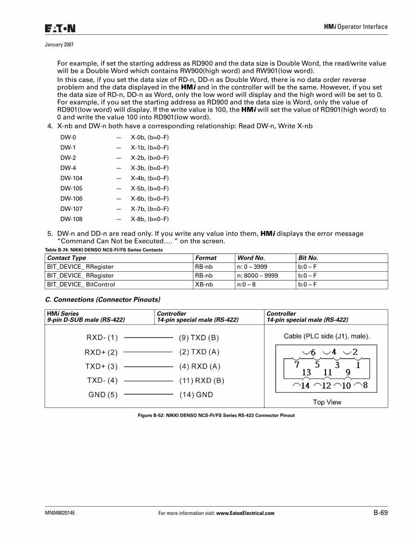
HMi Operator Interface
January 2007
For example, if set the starting address as RD900 and the data size is Double Word, the read/write value will be a Double Word which contains RW900(high word) and RW901(low word).In this case, if you set the data size of RD-n, DD-n as Double Word, there is no data order reverse problem and the data displayed in the HMi and in the controller will be the same. However, if you set the data size of RD-n, DD-n as Word, only the low word will display and the high word will be set to 0. For example, if you set the starting address as RD900 and the data size is Word, only the value of RD901(low word) will display. If the write value is 100, the HMi will set the value of RD901(high word) to 0 and write the value 100 into RD901(low word).
4. X-nb and DW-n both have a corresponding relationship: Read DW-n, Write X-nb
5. DW-n and DD-n are read only. If you write any value into them, HMi displays the error message “Command Can Not be Executed…. ” on the screen.
Table B-74: NIKKI DENSO NCS-FI/FS Series Contacts
C. Connections (Connector Pinouts)
Figure B-52: NIKKI DENSO NCS-FI/FS Series RS-422 Connector Pinout
DW-0 — X-0b, (b=0–F)
DW-1 — X-1b, (b=0–F)
DW-2 — X-2b, (b=0–F)
DW-4 — X-3b, (b=0–F)
DW-104 — X-4b, (b=0–F)
DW-105 — X-5b, (b=0–F)
DW-106 — X-6b, (b=0–F)
DW-107 — X-7b, (b=0–F)
DW-108 — X-8b, (b=0–F)
Contact Type Format Word No. Bit No.
BIT_DEVICE_ RRegister RB-nb n: 0 – 3999 b:0 – F BIT_DEVICE_ RRegister RB-nb n: 8000 – 9999 b:0 – FBIT_DEVICE_ BitControl XB-nb n:0 – 8 b:0 – F
HMi Series9-pin D-SUB male (RS-422)
Controller14-pin special male (RS-422)
Controller14-pin special male (RS-422)
MN04802014E For more information visit: www.EatonElectrical.com B-69
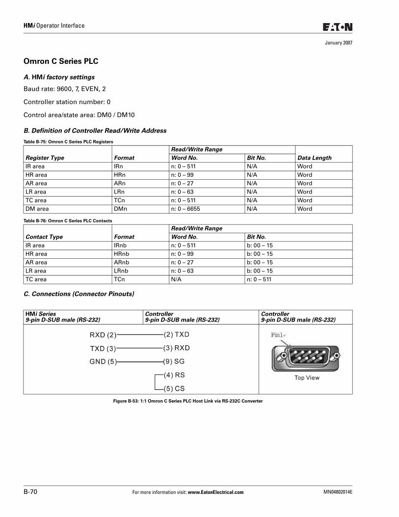
HMi Operator Interface
January 2007
Omron C Series PLC
A. HMi factory settings
Baud rate: 9600, 7, EVEN, 2
Controller station number: 0
Control area/state area: DM0 / DM10
B. Definition of Controller Read/Write Address
Table B-75: Omron C Series PLC Registers
Table B-76: Omron C Series PLC Contacts
C. Connections (Connector Pinouts)
Figure B-53: 1:1 Omron C Series PLC Host Link via RS-232C Converter
Register Type Format
Read/Write Range
Data LengthWord No. Bit No.
IR area IRn n: 0 – 511 N/A WordHR area HRn n: 0 – 99 N/A WordAR area ARn n: 0 – 27 N/A WordLR area LRn n: 0 – 63 N/A WordTC area TCn n: 0 – 511 N/A WordDM area DMn n: 0 – 6655 N/A Word
Contact Type Format
Read/Write Range
Word No. Bit No.
IR area IRnb n: 0 – 511 b: 00 – 15HR area HRnb n: 0 – 99 b: 00 – 15AR area ARnb n: 0 – 27 b: 00 – 15LR area LRnb n: 0 – 63 b: 00 – 15TC area TCn N/A n: 0 – 511
HMi Series9-pin D-SUB male (RS-232)
Controller9-pin D-SUB male (RS-232)
Controller9-pin D-SUB male (RS-232)
B-70 For more information visit: www.EatonElectrical.com MN04802014E
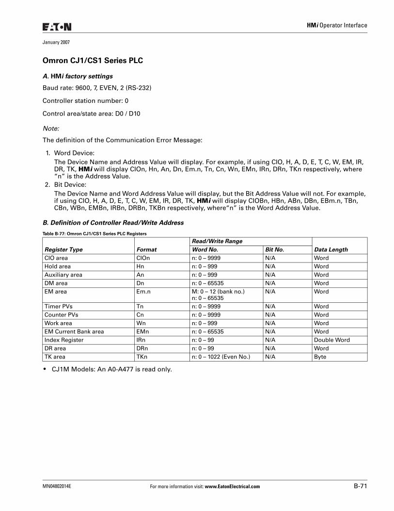
HMi Operator Interface
January 2007
Omron CJ1/CS1 Series PLC
A. HMi factory settings
Baud rate: 9600, 7, EVEN, 2 (RS-232)
Controller station number: 0
Control area/state area: D0 / D10
Note:
The definition of the Communication Error Message:
1. Word Device:The Device Name and Address Value will display. For example, if using CIO, H, A, D, E, T, C, W, EM, IR, DR, TK, HMi will display CIOn, Hn, An, Dn, Em.n, Tn, Cn, Wn, EMn, IRn, DRn, TKn respectively, where “n” is the Address Value.
2. Bit Device:The Device Name and Word Address Value will display, but the Bit Address Value will not. For example, if using CIO, H, A, D, E, T, C, W, EM, IR, DR, TK, HMi will display CIOBn, HBn, ABn, DBn, EBm.n, TBn, CBn, WBn, EMBn, IRBn, DRBn, TKBn respectively, where“n” is the Word Address Value.
B. Definition of Controller Read/Write Address
Table B-77: Omron CJ1/CS1 Series PLC Registers
● CJ1M Models: An A0-A477 is read only.
Register Type Format
Read/Write Range
Data LengthWord No. Bit No.
CIO area CIOn n: 0 – 9999 N/A WordHold area Hn n: 0 – 999 N/A WordAuxiliary area An n: 0 – 999 N/A WordDM area Dn n: 0 – 65535 N/A WordEM area Em.n M: 0 – 12 (bank no.)
n: 0 – 65535N/A Word
Timer PVs Tn n: 0 – 9999 N/A WordCounter PVs Cn n: 0 – 9999 N/A WordWork area Wn n: 0 – 999 N/A WordEM Current Bank area EMn n: 0 – 65535 N/A WordIndex Register IRn n: 0 – 99 N/A Double WordDR area DRn n: 0 – 99 N/A WordTK area TKn n: 0 – 1022 (Even No.) N/A Byte
MN04802014E For more information visit: www.EatonElectrical.com B-71
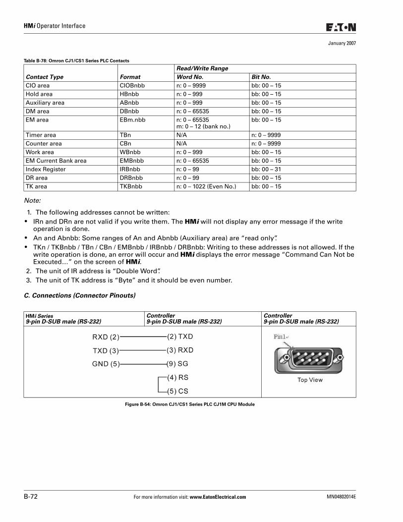
HMi Operator Interface
January 2007
Table B-78: Omron CJ1/CS1 Series PLC Contacts
Note:
1. The following addresses cannot be written: ● IRn and DRn are not valid if you write them. The HMi will not display any error message if the write
operation is done. ● An and Abnbb: Some ranges of An and Abnbb (Auxiliary area) are “read only”. ● TKn / TKBnbb / TBn / CBn / EMBnbb / IRBnbb / DRBnbb: Writing to these addresses is not allowed. If the
write operation is done, an error will occur and HMi displays the error message “Command Can Not be Executed…” on the screen of HMi.
2. The unit of IR address is “Double Word”.3. The unit of TK address is “Byte” and it should be even number.
C. Connections (Connector Pinouts)
Figure B-54: Omron CJ1/CS1 Series PLC CJ1M CPU Module
Contact Type Format
Read/Write Range
Word No. Bit No.
CIO area CIOBnbb n: 0 – 9999 bb: 00 – 15Hold area HBnbb n: 0 – 999 bb: 00 – 15Auxiliary area ABnbb n: 0 – 999 bb: 00 – 15DM area DBnbb n: 0 – 65535 bb: 00 – 15EM area EBm.nbb n: 0 – 65535
m: 0 – 12 (bank no.)bb: 00 – 15
Timer area TBn N/A n: 0 – 9999 Counter area CBn N/A n: 0 – 9999Work area WBnbb n: 0 – 999 bb: 00 – 15EM Current Bank area EMBnbb n: 0 – 65535 bb: 00 – 15Index Register IRBnbb n: 0 – 99 bb: 00 – 31DR area DRBnbb n: 0 – 99 bb: 00 – 15TK area TKBnbb n: 0 – 1022 (Even No.) bb: 00 – 15
HMi Series9-pin D-SUB male (RS-232)
Controller9-pin D-SUB male (RS-232)
Controller9-pin D-SUB male (RS-232)
B-72 For more information visit: www.EatonElectrical.com MN04802014E
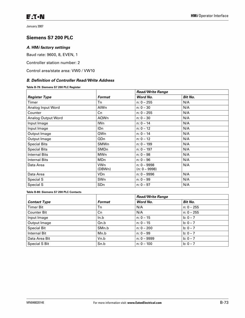
HMi Operator Interface
January 2007
Siemens S7 200 PLC
A. HMi factory settings
Baud rate: 9600, 8, EVEN, 1
Controller station number: 2
Control area/state area: VW0 / VW10
B. Definition of Controller Read/Write Address
Table B-79: Siemens S7 200 PLC Register
Table B-80: Siemens S7 200 PLC Contacts
Register Type Format
Read/Write Range
Word No. Bit No.
Timer Tn n: 0 – 255 N/AAnalog Input Word AIWn n: 0 – 30 N/ACounter Cn n: 0 – 255 N/AAnalog Output Word AQWn n: 0 – 30 N/AInput Image IWn n: 0 – 14 N/AInput Image IDn n: 0 – 12 N/AOutput Image QWn n: 0 – 14 N/AOutput Image QDn n: 0 – 12 N/ASpecial Bits SMWn n: 0 – 199 N/ASpecial Bits SMDn n: 0 – 197 N/AInternal Bits MWn n: 0 – 98 N/AInternal Bits MDn n: 0 – 96 N/AData Area VWn
(DBWn)n: 0 – 9998(n: 0 – 9998)
N/A
Data Area VDn n: 0 – 9996 N/ASpecial S SWn n: 0 – 99 N/ASpecial S SDn n: 0 – 97 N/A
Contact Type Format
Read/Write Range
Word No. Bit No.
Timer Bit Tn N/A n: 0 – 255Counter Bit Cn N/A n: 0 – 255Input Image In.b n: 0 – 15 b: 0 – 7Output Image Qn.b n: 0 – 15 b: 0 – 7Special Bit SMn.b n: 0 – 200 b: 0 – 7Internal Bit Mn.b n: 0 – 99 b: 0 – 7Data Area Bit Vn.b n: 0 – 9999 b: 0 – 7Special S Bit Sn.b n: 0 – 100 b: 0 – 7
MN04802014E For more information visit: www.EatonElectrical.com B-73
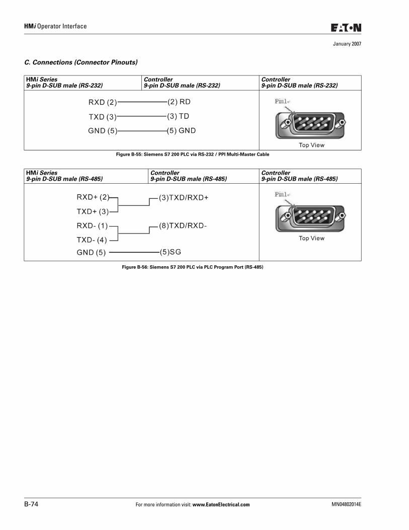
HMi Operator Interface
January 2007
C. Connections (Connector Pinouts)
Figure B-55: Siemens S7 200 PLC via RS-232 / PPI Multi-Master Cable
Figure B-56: Siemens S7 200 PLC via PLC Program Port (RS-485)
HMi Series9-pin D-SUB male (RS-232)
Controller9-pin D-SUB male (RS-232)
Controller9-pin D-SUB male (RS-232)
HMi Series9-pin D-SUB male (RS-485)
Controller9-pin D-SUB male (RS-485)
Controller9-pin D-SUB male (RS-485)
B-74 For more information visit: www.EatonElectrical.com MN04802014E
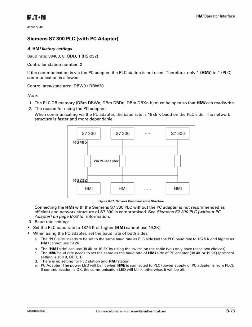
HMi Operator Interface
January 2007
Siemens S7 300 PLC (with PC Adapter)
A. HMi factory settings
Baud rate: 38400, 8, ODD, 1 (RS-232)
Controller station number: 2
If the communication is via the PC adapter, the PLC station is not used. Therefore, only 1 (HMi) to 1 (PLC) communication is allowed.
Control area/state area: DBW0 / DBW20
Note:
1. The PLC DB memory (DBm.DBWn, DBm.DBDn, DBm.DBXn.b) must be open so that HMi can read/write.2. The reason for using the PC adapter:
When communicating via the PC adapter, the baud rate is 187.5 K baud on the PLC side. The network structure is faster and more dependable.
Figure B-57: Network Communication Structure
Connecting the HMi with the Siemens S7 300 PLC without the PC adapter is not recommended as efficient and network structure of S7 300 is compromised. See Siemens S7 300 PLC (without PC Adapter) on page B-78 for information.
3. Baud rate setting: ● Set the PLC baud rate to 187.5 K or higher (HMi cannot use 19.2K). ● When using the PC adapter, set the baud rate of both sides:
a. The "PLC side" needs to be set to the same baud rate as PLC side (set the PLC baud rate to 187.5 K and higher as HMi cannot use 19.2K).
b. The "HMi side" can use 38.4K or 19.2K by using the switch on the cable (you only have these two choices).c. The HMi baud rate needs to set the same as the baud rate of HMi side of PC adapter (38.4K or 19.2K) (protocol
setting is still 8, ODD, 1).d. There is no setting for PLC station and HMi station.e. PC Adapter: The power LED will be lit when HMi is connected to PLC (power supply of PC adapter is from PLC).
If communication is OK, the communication LED will blink, otherwise, it will be off.
MN04802014E For more information visit: www.EatonElectrical.com B-75
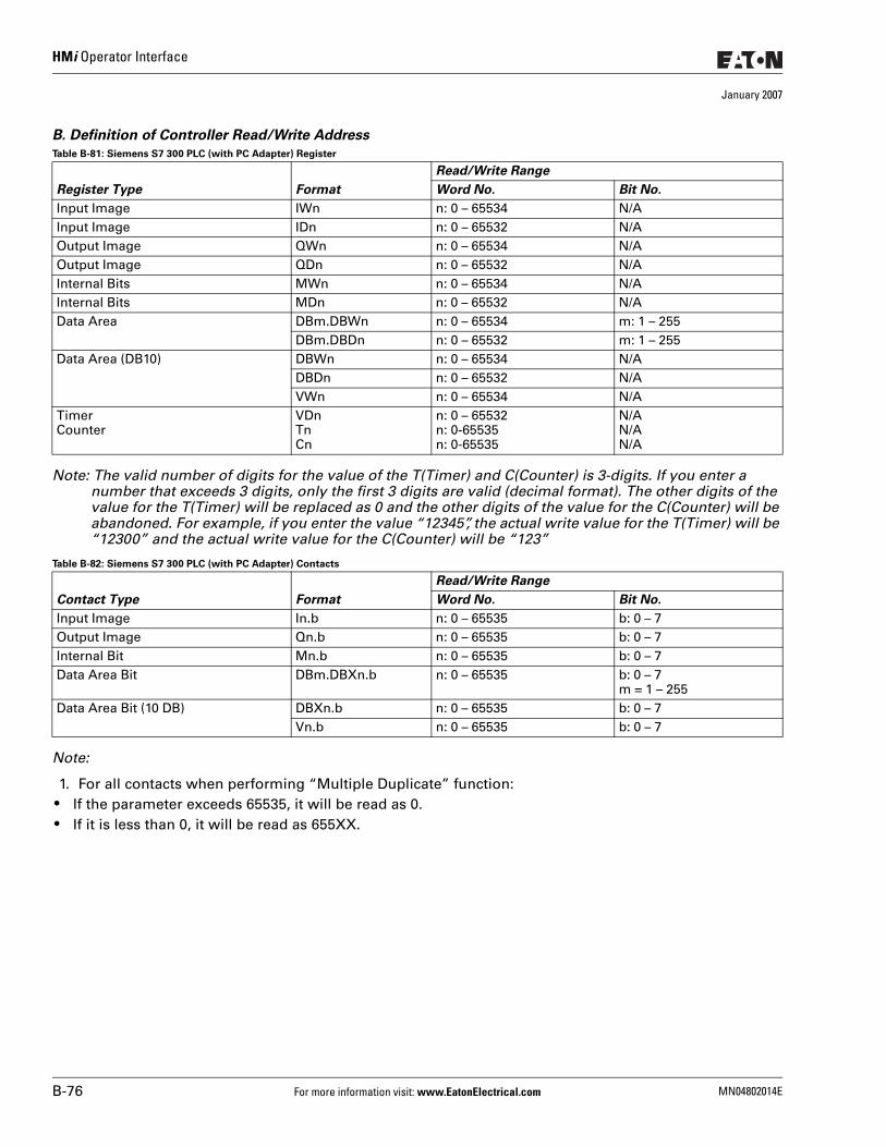
HMi Operator Interface
January 2007
B. Definition of Controller Read/Write Address
Table B-81: Siemens S7 300 PLC (with PC Adapter) Register
Note: The valid number of digits for the value of the T(Timer) and C(Counter) is 3-digits. If you enter a number that exceeds 3 digits, only the first 3 digits are valid (decimal format). The other digits of the value for the T(Timer) will be replaced as 0 and the other digits of the value for the C(Counter) will be abandoned. For example, if you enter the value “12345”, the actual write value for the T(Timer) will be “12300” and the actual write value for the C(Counter) will be “123”
Table B-82: Siemens S7 300 PLC (with PC Adapter) Contacts
Note:
1. For all contacts when performing “Multiple Duplicate” function: ● If the parameter exceeds 65535, it will be read as 0. ● If it is less than 0, it will be read as 655XX.
Register Type Format
Read/Write Range
Word No. Bit No.
Input Image IWn n: 0 – 65534 N/AInput Image IDn n: 0 – 65532 N/AOutput Image QWn n: 0 – 65534 N/AOutput Image QDn n: 0 – 65532 N/AInternal Bits MWn n: 0 – 65534 N/AInternal Bits MDn n: 0 – 65532 N/AData Area DBm.DBWn n: 0 – 65534 m: 1 – 255
DBm.DBDn n: 0 – 65532 m: 1 – 255Data Area (DB10) DBWn n: 0 – 65534 N/A
DBDn n: 0 – 65532 N/AVWn n: 0 – 65534 N/A
TimerCounter
VDnTnCn
n: 0 – 65532n: 0-65535n: 0-65535
N/AN/AN/A
Contact Type Format
Read/Write Range
Word No. Bit No.
Input Image In.b n: 0 – 65535 b: 0 – 7Output Image Qn.b n: 0 – 65535 b: 0 – 7Internal Bit Mn.b n: 0 – 65535 b: 0 – 7Data Area Bit DBm.DBXn.b n: 0 – 65535 b: 0 – 7
m = 1 – 255Data Area Bit (10 DB) DBXn.b n: 0 – 65535 b: 0 – 7
Vn.b n: 0 – 65535 b: 0 – 7
B-76 For more information visit: www.EatonElectrical.com MN04802014E
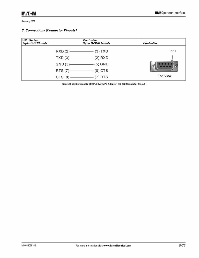
HMi Operator Interface
January 2007
C. Connections (Connector Pinouts)
Figure B-58: Siemens S7 300 PLC (with PC Adapter) RS-232 Connector Pinout
HMi Series9-pin D-SUB male
Controller9-pin D-SUB female Controller
MN04802014E For more information visit: www.EatonElectrical.com B-77
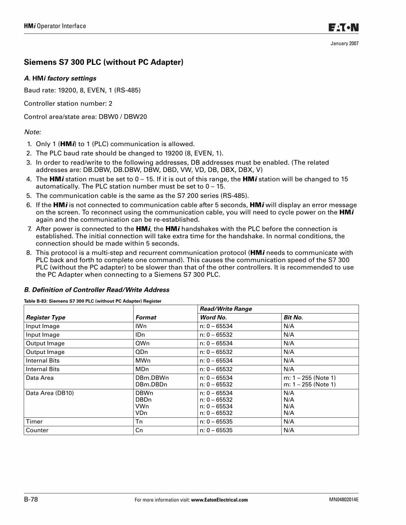
HMi Operator Interface
January 2007
Siemens S7 300 PLC (without PC Adapter)
A. HMi factory settings
Baud rate: 19200, 8, EVEN, 1 (RS-485)
Controller station number: 2
Control area/state area: DBW0 / DBW20
Note:
1. Only 1 (HMi) to 1 (PLC) communication is allowed.2. The PLC baud rate should be changed to 19200 (8, EVEN, 1).3. In order to read/write to the following addresses, DB addresses must be enabled. (The related
addresses are: DB.DBW, DB.DBW, DBW, DBD, VW, VD, DB, DBX, DBX, V)4. The HMi station must be set to 0 – 15. If it is out of this range, the HMi station will be changed to 15
automatically. The PLC station number must be set to 0 – 15.5. The communication cable is the same as the S7 200 series (RS-485).6. If the HMi is not connected to communication cable after 5 seconds, HMi will display an error message
on the screen. To reconnect using the communication cable, you will need to cycle power on the HMi again and the communication can be re-established.
7. After power is connected to the HMi, the HMi handshakes with the PLC before the connection is established. The initial connection will take extra time for the handshake. In normal conditions, the connection should be made within 5 seconds.
8. This protocol is a multi-step and recurrent communication protocol (HMi needs to communicate with PLC back and forth to complete one command). This causes the communication speed of the S7 300 PLC (without the PC adapter) to be slower than that of the other controllers. It is recommended to use the PC Adapter when connecting to a Siemens S7 300 PLC.
B. Definition of Controller Read/Write Address
Table B-83: Siemens S7 300 PLC (without PC Adapter) Register
Register Type Format
Read/Write Range
Word No. Bit No.
Input Image IWn n: 0 – 65534 N/AInput Image IDn n: 0 – 65532 N/AOutput Image QWn n: 0 – 65534 N/AOutput Image QDn n: 0 – 65532 N/AInternal Bits MWn n: 0 – 65534 N/AInternal Bits MDn n: 0 – 65532 N/AData Area DBm.DBWn
DBm.DBDnn: 0 – 65534n: 0 – 65532
m: 1 – 255 (Note 1)m: 1 – 255 (Note 1)
Data Area (DB10) DBWnDBDnVWnVDn
n: 0 – 65534n: 0 – 65532n: 0 – 65534n: 0 – 65532
N/AN/AN/AN/A
Timer Tn n: 0 – 65535 N/ACounter Cn n: 0 – 65535 N/A
B-78 For more information visit: www.EatonElectrical.com MN04802014E
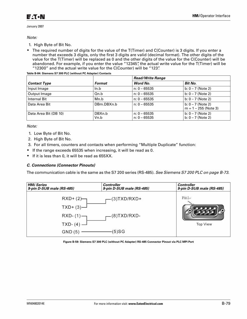
HMi Operator Interface
January 2007
Note:
1. High Byte of Bit No. ● The required number of digits for the value of the T(Timer) and C(Counter) is 3 digits. If you enter a
number that exceeds 3 digits, only the first 3 digits are valid (decimal format). The other digits of the value for the T(Timer) will be replaced as 0 and the other digits of the value for the C(Counter) will be abandoned. For example, if you enter the value “12345”, the actual write value for the T(Timer) will be “12300” and the actual write value for the C(Counter) will be “123”.
Table B-84: Siemens S7 300 PLC (without PC Adapter) Contacts
Note:
1. Low Byte of Bit No.2. High Byte of Bit No.3. For all timers, counters and contacts when performing “Multiple Duplicate” function:
● If the range exceeds 65535 when increasing, it will be read as 0. ● If it is less than 0, it will be read as 655XX.
C. Connections (Connector Pinouts)
The communication cable is the same as the S7 200 series (RS-485). See Siemens S7 200 PLC on page B-73.
Figure B-59: Siemens S7 300 PLC (without PC Adapter) RS-485 Connector Pinout via PLC MPI Port
Contact Type Format
Read/Write Range
Word No. Bit No.
Input Image In.b n: 0 – 65535 b: 0 – 7 (Note 2)Output Image Qn.b n: 0 – 65535 b: 0 – 7 (Note 2)Internal Bit Mn.b n: 0 – 65535 b: 0 – 7 (Note 2)Data Area Bit DBm.DBXn.b n: 0 – 65535 b: 0 – 7 (Note 2)
m = 1 – 255 (Note 3)Data Area Bit (DB 10) DBXn.b
Vn.bn: 0 – 65535n: 0 – 65535
b: 0 – 7 (Note 2)b: 0 – 7 (Note 2)
HMi Series9-pin D-SUB male (RS-485)
Controller9-pin D-SUB male (RS-485)
Controller9-pin D-SUB male (RS-485)
MN04802014E For more information visit: www.EatonElectrical.com B-79
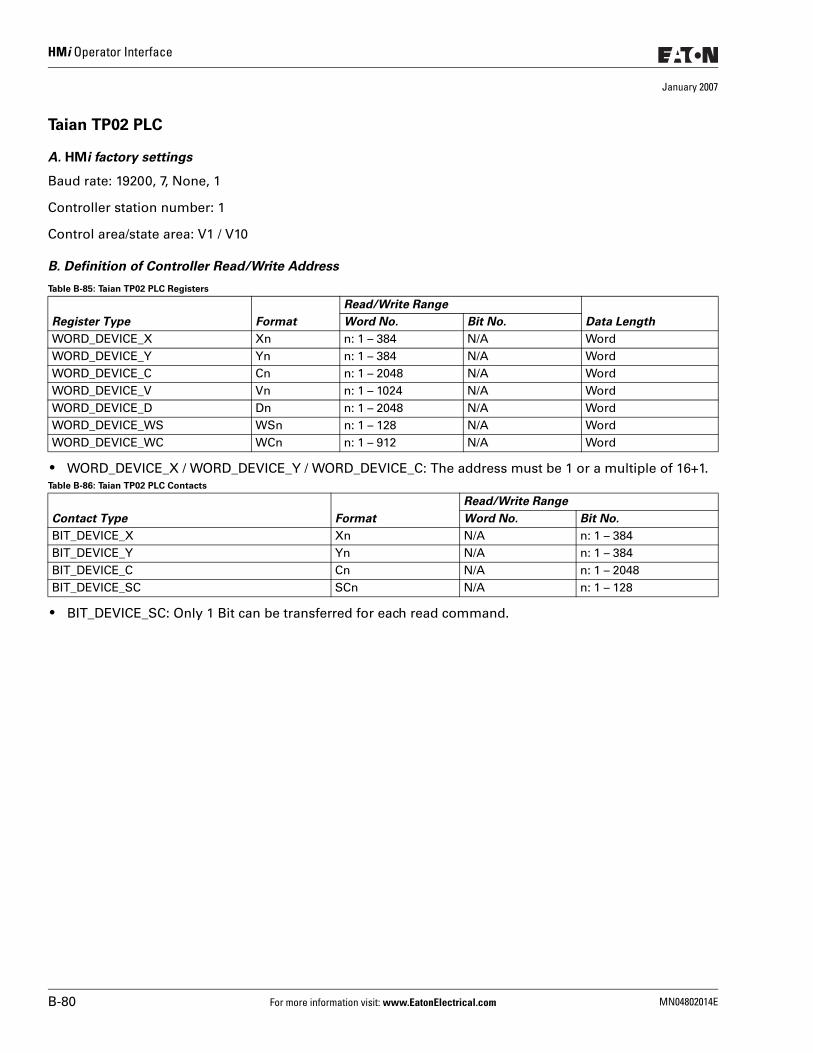
HMi Operator Interface
January 2007
Taian TP02 PLC
A. HMi factory settings
Baud rate: 19200, 7, None, 1
Controller station number: 1
Control area/state area: V1 / V10
B. Definition of Controller Read/Write Address
Table B-85: Taian TP02 PLC Registers
● WORD_DEVICE_X / WORD_DEVICE_Y / WORD_DEVICE_C: The address must be 1 or a multiple of 16+1.Table B-86: Taian TP02 PLC Contacts
● BIT_DEVICE_SC: Only 1 Bit can be transferred for each read command.
Register Type Format
Read/Write Range
Data LengthWord No. Bit No.
WORD_DEVICE_X Xn n: 1 – 384 N/A WordWORD_DEVICE_Y Yn n: 1 – 384 N/A WordWORD_DEVICE_C Cn n: 1 – 2048 N/A WordWORD_DEVICE_V Vn n: 1 – 1024 N/A WordWORD_DEVICE_D Dn n: 1 – 2048 N/A WordWORD_DEVICE_WS WSn n: 1 – 128 N/A WordWORD_DEVICE_WC WCn n: 1 – 912 N/A Word
Contact Type Format
Read/Write Range
Word No. Bit No.
BIT_DEVICE_X Xn N/A n: 1 – 384BIT_DEVICE_Y Yn N/A n: 1 – 384BIT_DEVICE_C Cn N/A n: 1 – 2048BIT_DEVICE_SC SCn N/A n: 1 – 128
B-80 For more information visit: www.EatonElectrical.com MN04802014E
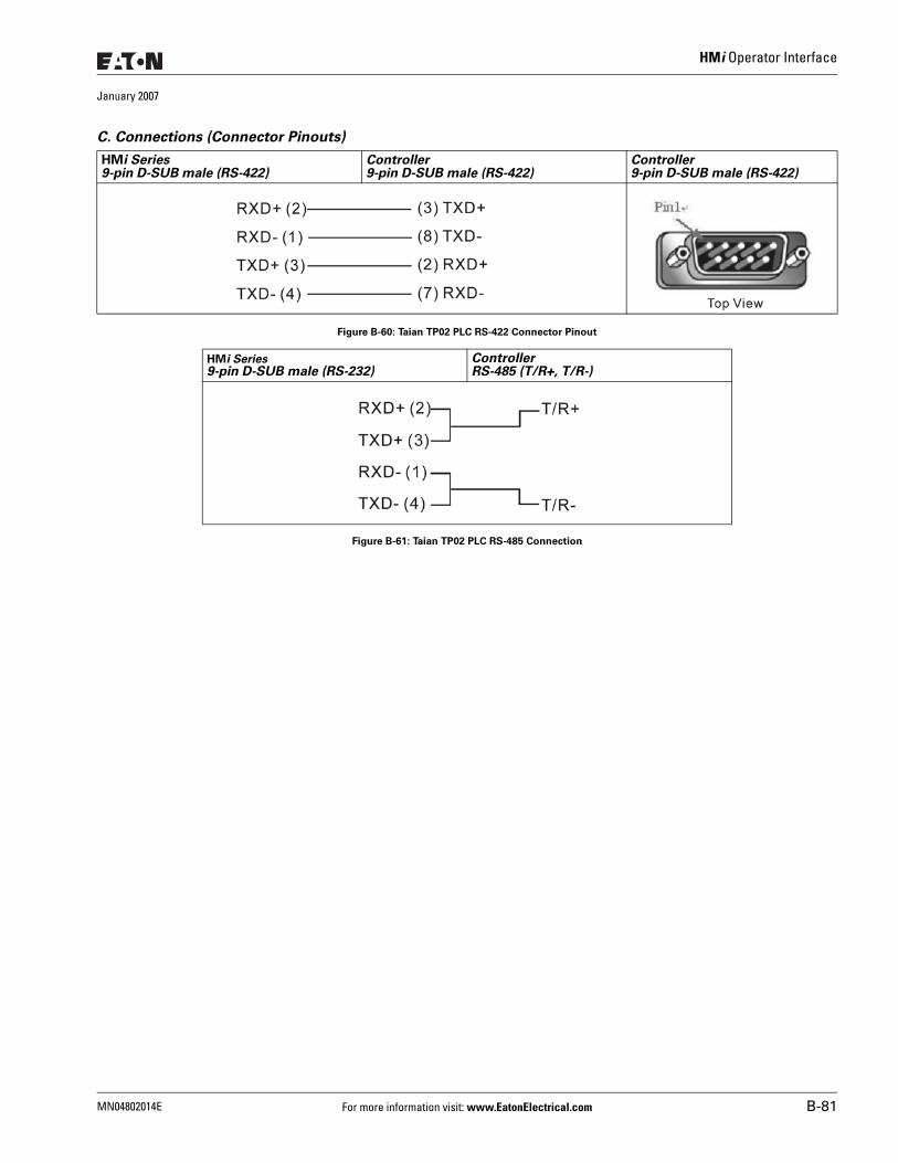
HMi Operator Interface
January 2007
C. Connections (Connector Pinouts)
Figure B-60: Taian TP02 PLC RS-422 Connector Pinout
Figure B-61: Taian TP02 PLC RS-485 Connection
HMi Series9-pin D-SUB male (RS-422)
Controller9-pin D-SUB male (RS-422)
Controller9-pin D-SUB male (RS-422)
HMi Series9-pin D-SUB male (RS-232)
ControllerRS-485 (T/R+, T/R-)
MN04802014E For more information visit: www.EatonElectrical.com B-81
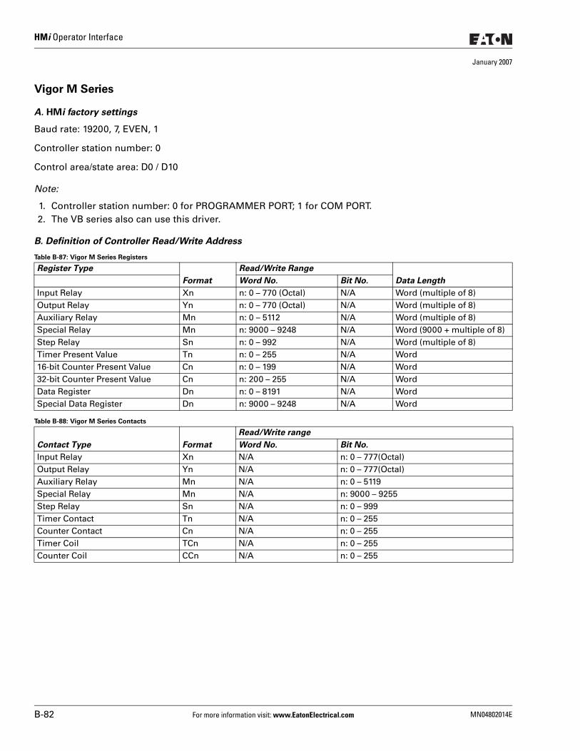
HMi Operator Interface
January 2007
Vigor M Series
A. HMi factory settings
Baud rate: 19200, 7, EVEN, 1
Controller station number: 0
Control area/state area: D0 / D10
Note:
1. Controller station number: 0 for PROGRAMMER PORT; 1 for COM PORT.2. The VB series also can use this driver.
B. Definition of Controller Read/Write Address
Table B-87: Vigor M Series Registers
Table B-88: Vigor M Series Contacts
Register Type
Format
Read/Write Range
Data LengthWord No. Bit No.
Input Relay Xn n: 0 – 770 (Octal) N/A Word (multiple of 8)Output Relay Yn n: 0 – 770 (Octal) N/A Word (multiple of 8)Auxiliary Relay Mn n: 0 – 5112 N/A Word (multiple of 8)Special Relay Mn n: 9000 – 9248 N/A Word (9000 + multiple of 8)Step Relay Sn n: 0 – 992 N/A Word (multiple of 8)Timer Present Value Tn n: 0 – 255 N/A Word16-bit Counter Present Value Cn n: 0 – 199 N/A Word32-bit Counter Present Value Cn n: 200 – 255 N/A WordData Register Dn n: 0 – 8191 N/A WordSpecial Data Register Dn n: 9000 – 9248 N/A Word
Contact Type Format
Read/Write range
Word No. Bit No.
Input Relay Xn N/A n: 0 – 777(Octal)Output Relay Yn N/A n: 0 – 777(Octal)Auxiliary Relay Mn N/A n: 0 – 5119Special Relay Mn N/A n: 9000 – 9255Step Relay Sn N/A n: 0 – 999Timer Contact Tn N/A n: 0 – 255Counter Contact Cn N/A n: 0 – 255Timer Coil TCn N/A n: 0 – 255Counter Coil CCn N/A n: 0 – 255
B-82 For more information visit: www.EatonElectrical.com MN04802014E
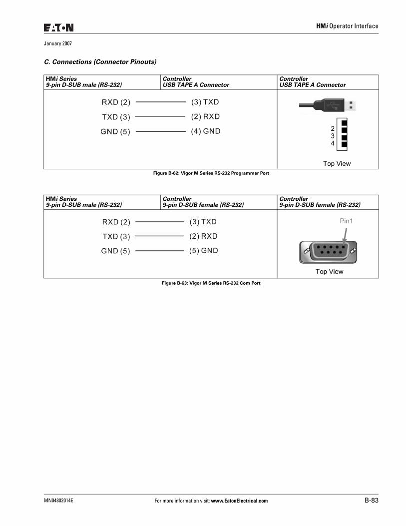
HMi Operator Interface
January 2007
C. Connections (Connector Pinouts)
Figure B-62: Vigor M Series RS-232 Programmer Port
Figure B-63: Vigor M Series RS-232 Com Port
HMi Series9-pin D-SUB male (RS-232)
ControllerUSB TAPE A Connector
ControllerUSB TAPE A Connector
HMi Series9-pin D-SUB male (RS-232)
Controller9-pin D-SUB female (RS-232)
Controller9-pin D-SUB female (RS-232)
MN04802014E For more information visit: www.EatonElectrical.com B-83
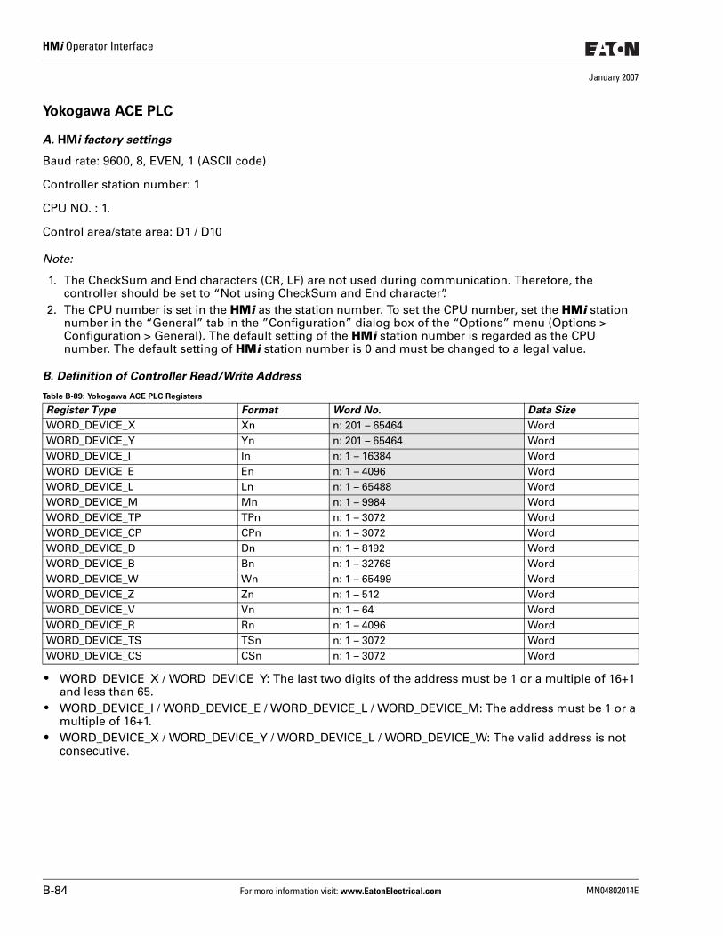
HMi Operator Interface
January 2007
Yokogawa ACE PLC
A. HMi factory settings
Baud rate: 9600, 8, EVEN, 1 (ASCII code)
Controller station number: 1
CPU NO. : 1.
Control area/state area: D1 / D10
Note:
1. The CheckSum and End characters (CR, LF) are not used during communication. Therefore, the controller should be set to “Not using CheckSum and End character”.
2. The CPU number is set in the HMi as the station number. To set the CPU number, set the HMi station number in the “General” tab in the ”Configuration” dialog box of the “Options” menu (Options > Configuration > General). The default setting of the HMi station number is regarded as the CPU number. The default setting of HMi station number is 0 and must be changed to a legal value.
B. Definition of Controller Read/Write Address
Table B-89: Yokogawa ACE PLC Registers
● WORD_DEVICE_X / WORD_DEVICE_Y: The last two digits of the address must be 1 or a multiple of 16+1 and less than 65.
● WORD_DEVICE_I / WORD_DEVICE_E / WORD_DEVICE_L / WORD_DEVICE_M: The address must be 1 or a multiple of 16+1.
● WORD_DEVICE_X / WORD_DEVICE_Y / WORD_DEVICE_L / WORD_DEVICE_W: The valid address is not consecutive.
Register Type Format Word No. Data Size
WORD_DEVICE_X Xn n: 201 – 65464 WordWORD_DEVICE_Y Yn n: 201 – 65464 WordWORD_DEVICE_I In n: 1 – 16384 WordWORD_DEVICE_E En n: 1 – 4096 WordWORD_DEVICE_L Ln n: 1 – 65488 WordWORD_DEVICE_M Mn n: 1 – 9984 WordWORD_DEVICE_TP TPn n: 1 – 3072 WordWORD_DEVICE_CP CPn n: 1 – 3072 WordWORD_DEVICE_D Dn n: 1 – 8192 WordWORD_DEVICE_B Bn n: 1 – 32768 WordWORD_DEVICE_W Wn n: 1 – 65499 WordWORD_DEVICE_Z Zn n: 1 – 512 WordWORD_DEVICE_V Vn n: 1 – 64 WordWORD_DEVICE_R Rn n: 1 – 4096 WordWORD_DEVICE_TS TSn n: 1 – 3072 WordWORD_DEVICE_CS CSn n: 1 – 3072 Word
B-84 For more information visit: www.EatonElectrical.com MN04802014E
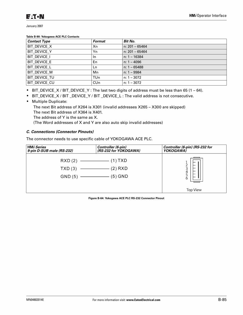
HMi Operator Interface
January 2007
Table B-90: Yokogawa ACE PLC Contacts
● BIT_DEVICE_X / BIT_DEVICE_Y : The last two digits of address must be less than 65 (1 – 64). ● BIT_DEVICE_X / BIT _DEVICE_Y / BIT _DEVICE_L : The valid address is not consecutive. ● Multiple Duplicate:
The next Bit address of X264 is X301 (invalid addresses X265 – X300 are skipped)The next Bit address of X364 is X401.The address of Y is the same as X.(The Word addresses of X and Y are also auto skip invalid addresses)
C. Connections (Connector Pinouts)
The connector needs to use specific cable of YOKOGAWA ACE PLC.
Figure B-64: Yokogawa ACE PLC RS-232 Connector Pinout
Contact Type Format Bit No.
BIT_DEVICE_X Xn n: 201 – 65464BIT_DEVICE_Y Yn n: 201 – 65464BIT_DEVICE_I In n: 1 – 16384BIT_DEVICE_E En n: 1 – 4096BIT_DEVICE_L Ln n: 1 – 65488BIT_DEVICE_M Mn n: 1 – 9984BIT_DEVICE_TU TUn n: 1 – 3072BIT_DEVICE_CU CUn n: 1 – 3072
HMi Series9-pin D-SUB male (RS-232)
Controller (6-pin)(RS-232 for YOKOGAWA)
Controller (6-pin) (RS-232 for YOKOGAWA)
MN04802014E For more information visit: www.EatonElectrical.com B-85

HMi Operator Interface
January 2007
B-86 For more information visit: www.EatonElectrical.com MN04802014E


Company InformationEaton’s electrical business is a global leader in electrical control, power distribution, and industrial automation products and services. Through advanced product development, world-class manufacturing methods, and global engineering services and support, Eaton’s electrical business provides customer-driven solutions under brand names such as Cutler-Hammer®, Powerware®, Durant®, Heinemann®, Holec® and MEM®, which globally serve the changing needs of the industrial, utility, light commercial, residential, and OEM markets. For more information, visit www.EatonElectrical.com.
Eaton Corporation is a diversified industrial manufacturer with 2005 sales of $11.1 billion. Eaton is a global leader in electrical systems and components for power quality, distribution and control; fluid power systems and services for industrial, mobile and aircraft equipment; intelligent truck drivetrain systems for safety and fuel economy; and automotive engine air management systems, powertrain solutions and specialty controls for performance, fuel economy and safety. Eaton has 60,000 employees and sells products to customers in more than 125 countries. For more information, visit www.eaton.com.
Eaton Electrical Inc.1000 Cherrington ParkwayMoon Township, PA 15108-4312USAtel: 1-800-525-2000www.EatonElectrical.com
© 2007 Eaton CorporationAll Rights ReservedPrinted in USAPublication No. MN04802014EJanuary 2007