Embed Size (px)
Citation preview
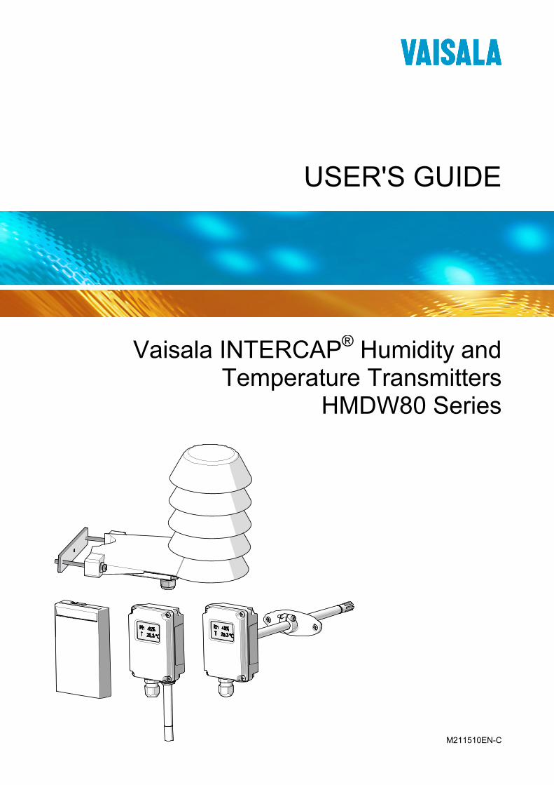
USER'S GUIDE
Vaisala INTERCAP® Humidity and Temperature Transmitters
HMDW80 Series
M211510EN-C
PUBLISHED BY
Vaisala Oyj Phone (int.): +358 9 8949 1 P.O. Box 26 Fax: +358 9 8949 2227 FI-00421 Helsinki Finland
Visit our Internet pages at www.vaisala.com.
© Vaisala 2013
No part of this manual may be reproduced, published or publicly displayed in any form or by any means, electronic or mechanical (including photocopying), nor may its contents be modified, translated, adapted, sold or disclosed to a third party without prior written permission of the copyright holder. Translated manuals and translated portions of multilingual documents are based on the original English versions. In ambiguous cases, the English versions are applicable, not the translations.
The contents of this manual are subject to change without prior notice.
This manual does not create any legally binding obligations for Vaisala towards customers or end users. All legally binding obligations and agreements are included exclusively in the applicable supply contract or the General Conditions of Sale and General Conditions of Service of Vaisala.
_________________________________________________________________________________
VAISALA _________________________________________________________________________ 1
Table of Contents
CHAPTER 1 GENERAL INFORMATION ............................................................................ 5
About This Manual ................................................................... 5 Contents of This Manual ....................................................... 5 Version Information ............................................................... 6 Related Manuals ................................................................... 6 Documentation Conventions ................................................. 6
Safety ......................................................................................... 7 ESD Protection ...................................................................... 7
Recycling .................................................................................. 7 Regulatory Compliances ......................................................... 8 Trademarks ............................................................................... 8 Software License ...................................................................... 8 Warranty .................................................................................... 8
CHAPTER 2 PRODUCT OVERVIEW .................................................................................. 9
Introduction to HMDW80 Series ............................................. 9 HMDW80 Series Transmitter Models .................................... 10
Output Parameters Explained ............................................. 10 Transmitter Parts – Duct Models .......................................... 11 Transmitter Parts – Wall Models ........................................... 12 Transmitter Parts – Outdoor Models .................................... 14 Display ..................................................................................... 15 Analog Output Overrange Behavior ..................................... 16
CHAPTER 3 INSTALLATION ............................................................................................ 17
Selecting Location ................................................................. 17 Installing Duct Models HMD82/83 and TMD82/83 ............... 18 Installing Wall Models HMW88 and HMW89 ........................ 20 Installing Wall Models HMW82/83 and TMW82/83 .............. 21 Installing Outdoor Models HMS82/83 ................................... 22
Configuration and Wiring ..................................................... 23 Pole installation ................................................................... 24 Wall installation ................................................................... 25
Wiring ...................................................................................... 26 HMD82(D), HMW88(D), and HMS82 .................................. 26 TMD82 ................................................................................. 26 HMD83(D), HMW89(D), and HMS83 .................................. 27 TMD83 ................................................................................. 27 HMW82 ............................................................................... 28 TMW82 ................................................................................ 28 HMW83 ............................................................................... 29 TMW83 ................................................................................ 29
User's Guide _______________________________________________________________________
2 ____________________________________________________________________ M211510EN-C
DIP Switches ........................................................................... 30
CHAPTER 4 MAINTENANCE ............................................................................................ 33
Cleaning ................................................................................... 33 Calibration ............................................................................... 33 Replacing the INTERCAP® Humidity Sensor ....................... 34
Replacing the INTERCAP® Sensor on Models HMD82/83 and HMW88/89 .................................................................... 34 Replacing the INTERCAP® Sensor on Wall Models HMW82/83 ........................................................................... 35 Replacing the INTERCAP® Sensor on Outdoor Models HMS82/83 ............................................................................ 36
CHAPTER 5 TROUBLESHOOTING .................................................................................. 41
Problem Situations ................................................................. 41 Analog Output Error State ..................................................... 42 Error Messages on the Display ............................................. 42 Technical Support .................................................................. 43 Product Returns...................................................................... 43
CHAPTER 6 TECHNICAL DATA ...................................................................................... 45
Specifications ......................................................................... 45 Spare Parts and Accessories ................................................ 48

_________________________________________________________________________________
VAISALA _________________________________________________________________________ 3
List of Figures
Figure 1 Parts of Duct Mounted Models (HMD82/83 and TMD82/83) ... 11 Figure 2 Parts of Wall Mounted Models (HMW88/89) ............................ 12 Figure 3 Parts of Wall Mounted Models (HMW82/83 and TMW82/83) .. 13 Figure 4 Parts of Outdoor Models (HMS82/83) ...................................... 14 Figure 5 Startup Screens (HMD83D) ..................................................... 15 Figure 6 Measurement Screen (HMD83D) ............................................. 15 Figure 7 Measurement Screen with Error (HMD83D) ............................ 15 Figure 8 Duct Model Installation ............................................................. 19 Figure 9 Position the Sensor to Center of Duct ...................................... 19 Figure 10 Duct Model Dimensions (HMD82/83 and TMD82/83) .............. 19 Figure 11 Wall Model Dimensions (HMW88/89) ...................................... 20 Figure 12 Wall Model Dimensions (HMW82/83 and TMW82/83) ............ 21 Figure 13 Outdoor Model Dimensions (HMS82/83) ................................. 22 Figure 14 Location of DIP Switches and Screw Terminal ........................ 23 Figure 15 HMS82/83 Pole Installation ...................................................... 24 Figure 16 Securing the Cable on a Pole .................................................. 24 Figure 17 HMS82/83 Wall Installation ...................................................... 25 Figure 18 Securing the Cable on a Wall ................................................... 25 Figure 19 DIP Switches on Component Board ......................................... 30 Figure 20 Sensors on HMD82/83 and HMW88/89 Models ...................... 34 Figure 21 INTERCAP® Sensor on HMW82/83 Models ............................ 35 Figure 22 Unplugging the Screw Terminal ............................................... 36 Figure 23 Opening the Radiation Shield Screws ...................................... 37 Figure 24 Removing the Radiation Shield Screws ................................... 37 Figure 25 Location of Locking Tab ........................................................... 38 Figure 26 Removing the Radiation Shield ................................................ 38 Figure 27 Filter Removed ......................................................................... 39 Figure 28 Sensors on HMS82/83 Models ................................................ 39
List of Tables
Table 1 Manual Revisions ....................................................................... 6 Table 2 Related Manuals ........................................................................ 6 Table 3 HMDW80 Series Transmitter Models ....................................... 10 Table 4 Parameters Supported by HMDW80 Series ............................ 10 Table 5 DIP Switch Positions for Metric Output .................................... 31 Table 6 DIP Switch Positions for Non-Metric Output ............................ 31 Table 7 Possible Problem Situations and Their Remedies ................... 41 Table 8 Error Messages on the Display ................................................ 42 Table 9 Specifications for HMW82/83 and TMW82/83 ......................... 45 Table 10 Specifications for HMD82/83, TMD82/83, HMW88/89, and
HMS82/83 ................................................................................ 46 Table 11 Specifications for HMD82/83D and HMW88/89D .................... 47 Table 12 Operating Environment (All Models) ........................................ 47 Table 13 Inputs and Outputs ................................................................... 47 Table 14 Mechanics ................................................................................ 48 Table 15 HMDW80 Series Spare Parts and Accessories ....................... 48

User's Guide _______________________________________________________________________
4 ____________________________________________________________________ M211510EN-C
This page intentionally left blank.
Chapter 1 _________________________________________________________ General Information
VAISALA _________________________________________________________________________ 5
CHAPTER 1
GENERAL INFORMATION
This chapter provides general notes for the manual and the HMDW80 series.
About This Manual This manual provides information for installing, operating, and maintaining HMDW80 series transmitters.
Contents of This Manual This manual consists of the following chapters:
- Chapter 1, General Information, provides general notes for the manual and the HMDW80 series.
- Chapter 2, Product Overview, introduces the features and options of the HMDW80 series transmitters.
- Chapter 3, Installation, provides you with information that is intended to help you install HMDW80 series transmitters.
- Chapter 4, Maintenance, provides information that is needed in basic maintenance of HMDW80 series.
- Chapter 5, Troubleshooting, describes possible problems, their probable causes and remedies, and provides contact information for technical support.
- Chapter 6, Technical Data, provides the technical data of the HMDW80 series.
User's Guide _______________________________________________________________________
6 ____________________________________________________________________ M211510EN-C
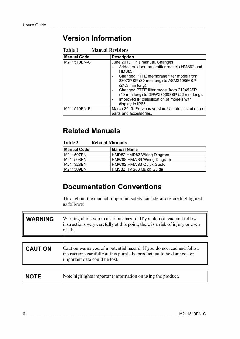
Version Information Table 1 Manual Revisions Manual Code Description M211510EN-C June 2013. This manual. Changes:
- Added outdoor transmitter models HMS82 and HMS83.
- Changed PTFE membrane filter model from 230727SP (30 mm long) to ASM210856SP (24.5 mm long).
- Changed PTFE filter model from 219452SP (40 mm long) to DRW239993SP (22 mm long).
- Improved IP classification of models with display to IP65.
M211510EN-B March 2013. Previous version. Updated list of spare parts and accessories.
Related Manuals Table 2 Related Manuals Manual Code Manual Name M211507EN HMD82 HMD83 Wiring Diagram M211508EN HMW88 HMW89 Wiring Diagram M211328EN HMW82 HMW83 Quick Guide M211509EN HMS82 HMS83 Quick Guide
Documentation Conventions Throughout the manual, important safety considerations are highlighted as follows:
WARNING Warning alerts you to a serious hazard. If you do not read and follow instructions very carefully at this point, there is a risk of injury or even death.
CAUTION Caution warns you of a potential hazard. If you do not read and follow instructions carefully at this point, the product could be damaged or important data could be lost.
NOTE Note highlights important information on using the product.
Chapter 1 _________________________________________________________ General Information
VAISALA _________________________________________________________________________ 7
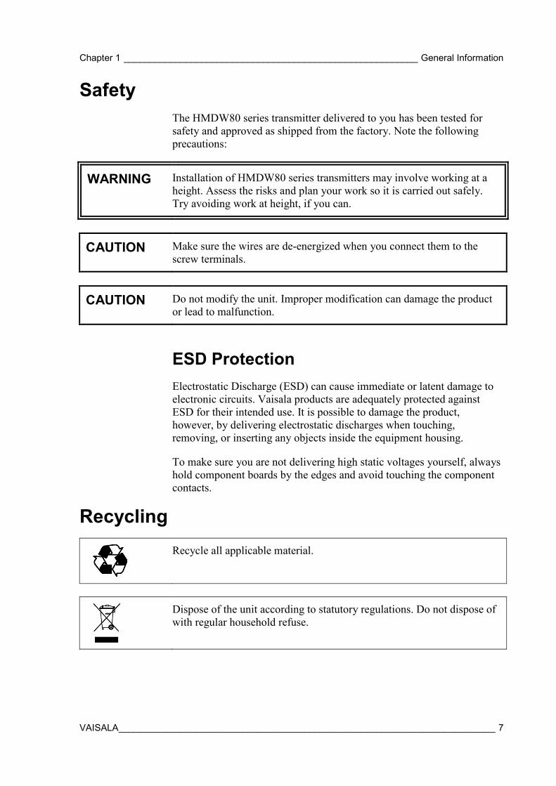
Safety The HMDW80 series transmitter delivered to you has been tested for safety and approved as shipped from the factory. Note the following precautions:
WARNING Installation of HMDW80 series transmitters may involve working at a height. Assess the risks and plan your work so it is carried out safely. Try avoiding work at height, if you can.
CAUTION Make sure the wires are de-energized when you connect them to the screw terminals.
CAUTION Do not modify the unit. Improper modification can damage the product or lead to malfunction.
ESD Protection Electrostatic Discharge (ESD) can cause immediate or latent damage to electronic circuits. Vaisala products are adequately protected against ESD for their intended use. It is possible to damage the product, however, by delivering electrostatic discharges when touching, removing, or inserting any objects inside the equipment housing.
To make sure you are not delivering high static voltages yourself, always hold component boards by the edges and avoid touching the component contacts.
Recycling
Recycle all applicable material.
Dispose of the unit according to statutory regulations. Do not dispose of with regular household refuse.

User's Guide _______________________________________________________________________
8 ____________________________________________________________________ M211510EN-C
Regulatory Compliances HMDW80 series complies with the following performance and environmental test standards:
- EMC-Directive
Conformity is shown by compliance with the following standards:
- EN 61326-1: Electrical equipment for measurement, control, and laboratory use – EMC requirements – For use in industrial locations.
- EN 550022: Information technology equipment – Radio disturbance characteristics – Limits and methods of measurement.
Trademarks INTERCAP® is a registered trademark of Vaisala Oyj.
Software License This product contains software developed by Vaisala. Use of the software is governed by license terms and conditions included in the applicable supply contract or, in the absence of separate license terms and conditions, by the General License Conditions of Vaisala Group.
Warranty Visit our Internet pages for standard warranty terms and conditions: www.vaisala.com/warranty.
Please observe that any such warranty may not be valid in case of damage due to normal wear and tear, exceptional operating conditions, negligent handling or installation, or unauthorized modifications. Please see the applicable supply contract or Conditions of Sale for details of the warranty for each product.
Chapter 2 ___________________________________________________________ Product Overview
VAISALA _________________________________________________________________________ 9
CHAPTER 2
PRODUCT OVERVIEW
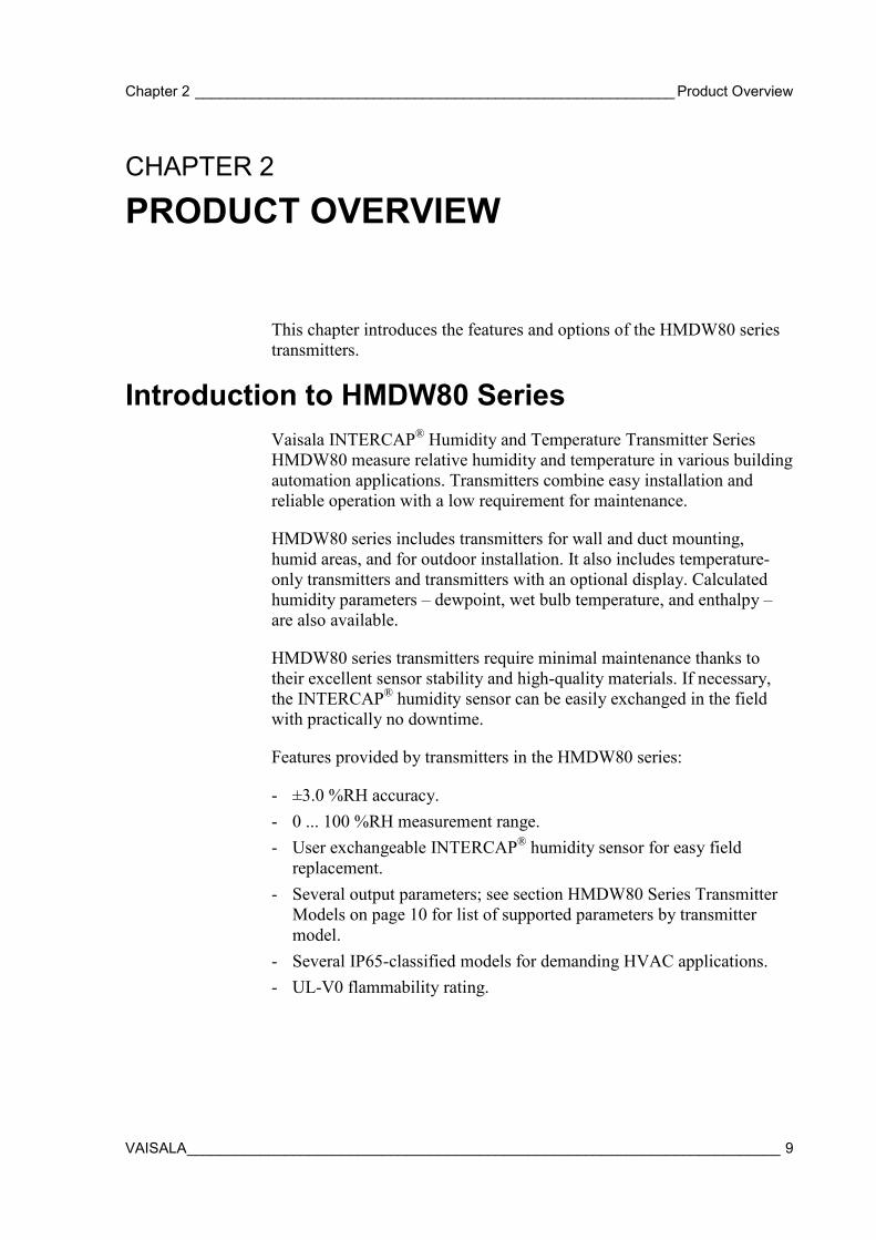
This chapter introduces the features and options of the HMDW80 series transmitters.
Introduction to HMDW80 Series Vaisala INTERCAP® Humidity and Temperature Transmitter Series HMDW80 measure relative humidity and temperature in various building automation applications. Transmitters combine easy installation and reliable operation with a low requirement for maintenance.
HMDW80 series includes transmitters for wall and duct mounting, humid areas, and for outdoor installation. It also includes temperature-only transmitters and transmitters with an optional display. Calculated humidity parameters – dewpoint, wet bulb temperature, and enthalpy – are also available.
HMDW80 series transmitters require minimal maintenance thanks to their excellent sensor stability and high-quality materials. If necessary, the INTERCAP® humidity sensor can be easily exchanged in the field with practically no downtime.
Features provided by transmitters in the HMDW80 series:
- ±3.0 %RH accuracy. - 0 ... 100 %RH measurement range. - User exchangeable INTERCAP® humidity sensor for easy field
replacement. - Several output parameters; see section HMDW80 Series Transmitter
Models on page 10 for list of supported parameters by transmitter model.
- Several IP65-classified models for demanding HVAC applications. - UL-V0 flammability rating.
User's Guide _______________________________________________________________________
10 ___________________________________________________________________ M211510EN-C
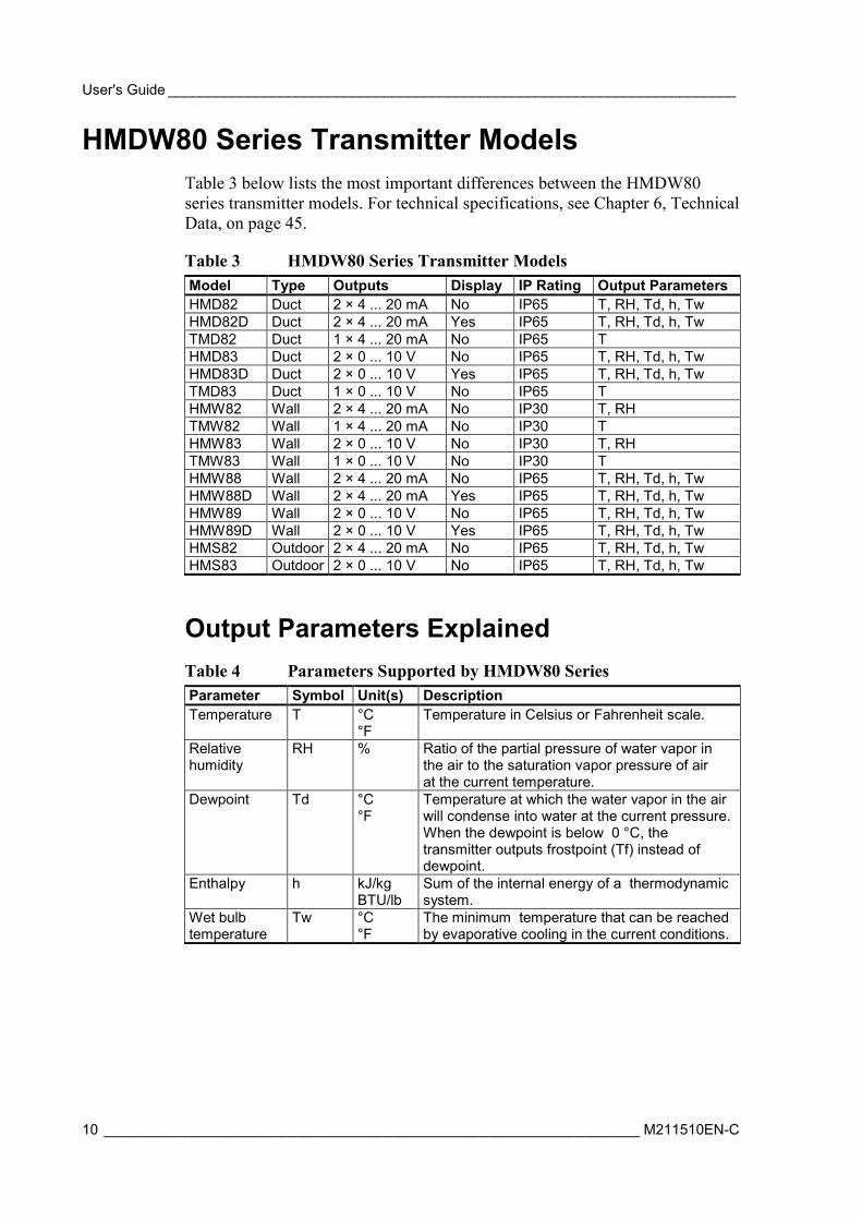
HMDW80 Series Transmitter Models Table 3 below lists the most important differences between the HMDW80 series transmitter models. For technical specifications, see Chapter 6, Technical Data, on page 45.
Table 3 HMDW80 Series Transmitter Models Model Type Outputs Display IP Rating Output Parameters HMD82 Duct 2 × 4 ... 20 mA No IP65 T, RH, Td, h, Tw HMD82D Duct 2 × 4 ... 20 mA Yes IP65 T, RH, Td, h, Tw TMD82 Duct 1 × 4 ... 20 mA No IP65 T HMD83 Duct 2 × 0 ... 10 V No IP65 T, RH, Td, h, Tw HMD83D Duct 2 × 0 ... 10 V Yes IP65 T, RH, Td, h, Tw TMD83 Duct 1 × 0 ... 10 V No IP65 T HMW82 Wall 2 × 4 ... 20 mA No IP30 T, RH TMW82 Wall 1 × 4 ... 20 mA No IP30 T HMW83 Wall 2 × 0 ... 10 V No IP30 T, RH TMW83 Wall 1 × 0 ... 10 V No IP30 T HMW88 Wall 2 × 4 ... 20 mA No IP65 T, RH, Td, h, Tw HMW88D Wall 2 × 4 ... 20 mA Yes IP65 T, RH, Td, h, Tw HMW89 Wall 2 × 0 ... 10 V No IP65 T, RH, Td, h, Tw HMW89D Wall 2 × 0 ... 10 V Yes IP65 T, RH, Td, h, Tw HMS82 Outdoor 2 × 4 ... 20 mA No IP65 T, RH, Td, h, Tw HMS83 Outdoor 2 × 0 ... 10 V No IP65 T, RH, Td, h, Tw
Output Parameters Explained Table 4 Parameters Supported by HMDW80 Series Parameter Symbol Unit(s) Description Temperature T °C
°F Temperature in Celsius or Fahrenheit scale.
Relative humidity
RH % Ratio of the partial pressure of water vapor in the air to the saturation vapor pressure of air at the current temperature.
Dewpoint Td °C °F
Temperature at which the water vapor in the air will condense into water at the current pressure. When the dewpoint is below 0 °C, the transmitter outputs frostpoint (Tf) instead of dewpoint.
Enthalpy h kJ/kg BTU/lb
Sum of the internal energy of a thermodynamic system.
Wet bulb temperature
Tw °C °F
The minimum temperature that can be reached by evaporative cooling in the current conditions.
Chapter 2 ___________________________________________________________ Product Overview
VAISALA ________________________________________________________________________ 11
Transmitter Parts – Duct Models
1302-018
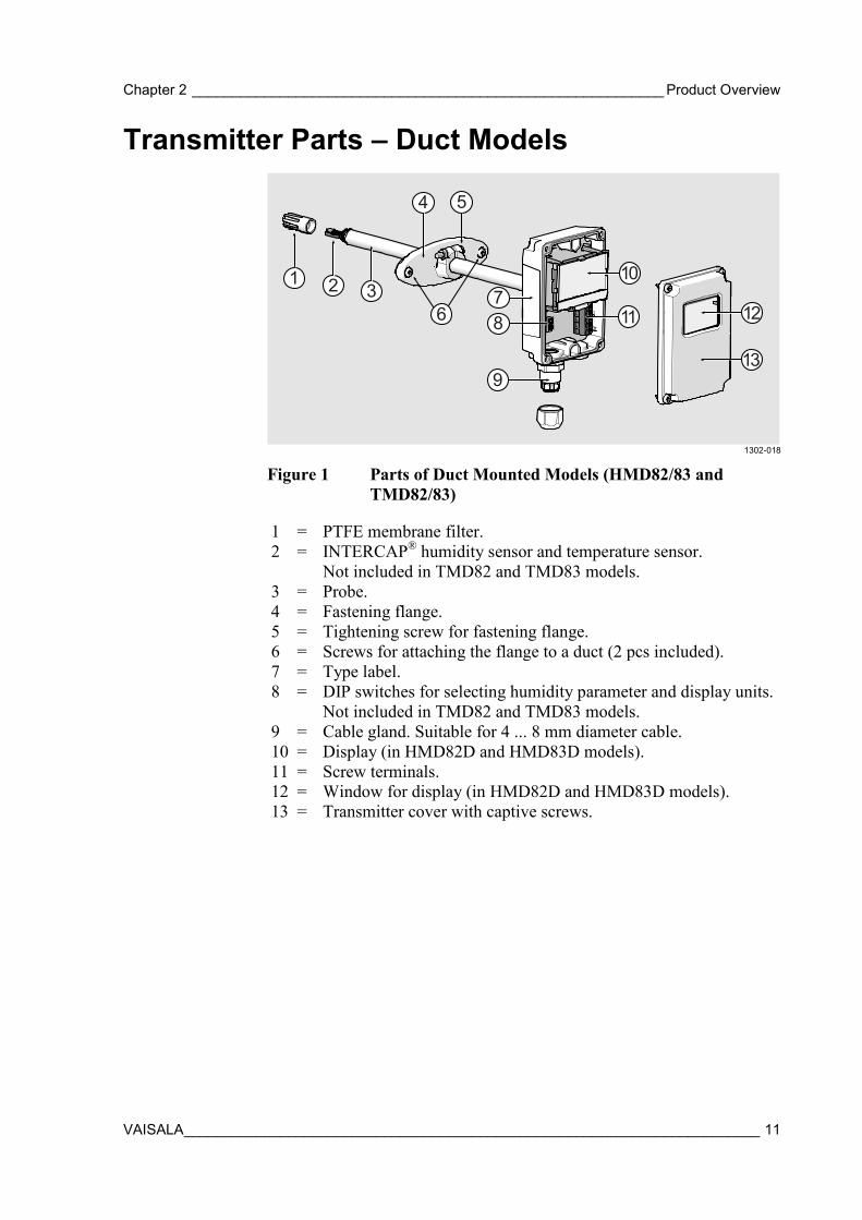
Figure 1 Parts of Duct Mounted Models (HMD82/83 and TMD82/83)
1 = PTFE membrane filter. 2 = INTERCAP® humidity sensor and temperature sensor.
Not included in TMD82 and TMD83 models. 3 = Probe. 4 = Fastening flange. 5 = Tightening screw for fastening flange. 6 = Screws for attaching the flange to a duct (2 pcs included). 7 = Type label. 8 = DIP switches for selecting humidity parameter and display units.
Not included in TMD82 and TMD83 models. 9 = Cable gland. Suitable for 4 ... 8 mm diameter cable. 10 = Display (in HMD82D and HMD83D models). 11 = Screw terminals. 12 = Window for display (in HMD82D and HMD83D models). 13 = Transmitter cover with captive screws.
5
1 26
4
78
9
11 12
13
310
User's Guide _______________________________________________________________________
12 ___________________________________________________________________ M211510EN-C
Transmitter Parts – Wall Models
1302-019
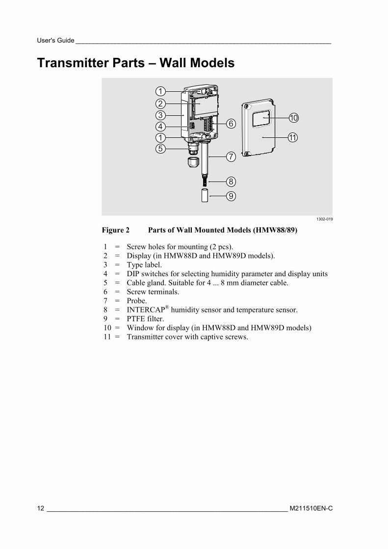
Figure 2 Parts of Wall Mounted Models (HMW88/89)
1 = Screw holes for mounting (2 pcs). 2 = Display (in HMW88D and HMW89D models). 3 = Type label. 4 = DIP switches for selecting humidity parameter and display units 5 = Cable gland. Suitable for 4 ... 8 mm diameter cable. 6 = Screw terminals. 7 = Probe. 8 = INTERCAP® humidity sensor and temperature sensor. 9 = PTFE filter. 10 = Window for display (in HMW88D and HMW89D models) 11 = Transmitter cover with captive screws.
1
11
23
64
51
8
7
9
10
Chapter 2 ___________________________________________________________ Product Overview
VAISALA ________________________________________________________________________ 13
1302-020
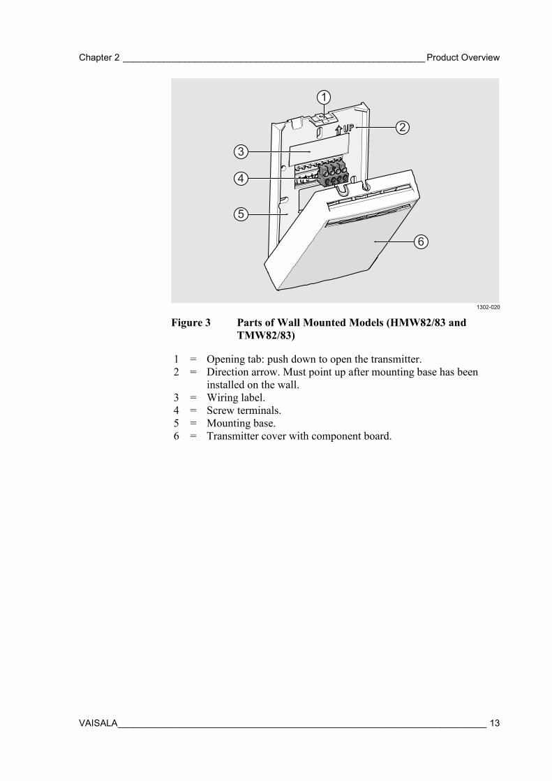
Figure 3 Parts of Wall Mounted Models (HMW82/83 and TMW82/83)
1 = Opening tab: push down to open the transmitter. 2 = Direction arrow. Must point up after mounting base has been
installed on the wall. 3 = Wiring label. 4 = Screw terminals. 5 = Mounting base. 6 = Transmitter cover with component board.
2
1
3
4
6
5
User's Guide _______________________________________________________________________
14 ___________________________________________________________________ M211510EN-C
Transmitter Parts – Outdoor Models
1304-048
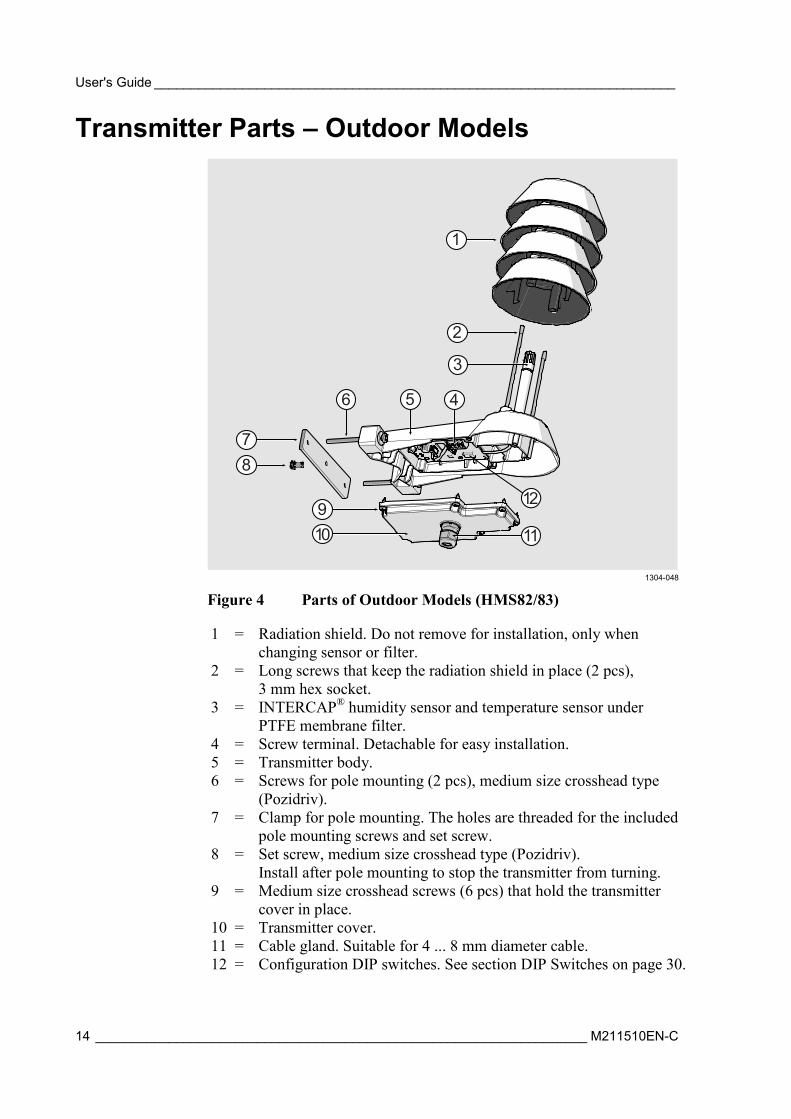
Figure 4 Parts of Outdoor Models (HMS82/83)
1 = Radiation shield. Do not remove for installation, only when changing sensor or filter.
2 = Long screws that keep the radiation shield in place (2 pcs), 3 mm hex socket.
3 = INTERCAP® humidity sensor and temperature sensor under PTFE membrane filter.
4 = Screw terminal. Detachable for easy installation. 5 = Transmitter body. 6 = Screws for pole mounting (2 pcs), medium size crosshead type
(Pozidriv). 7 = Clamp for pole mounting. The holes are threaded for the included
pole mounting screws and set screw. 8 = Set screw, medium size crosshead type (Pozidriv).
Install after pole mounting to stop the transmitter from turning. 9 = Medium size crosshead screws (6 pcs) that hold the transmitter
cover in place. 10 = Transmitter cover. 11 = Cable gland. Suitable for 4 ... 8 mm diameter cable. 12 = Configuration DIP switches. See section DIP Switches on page 30.
1
2
3
78
6 5
11
4
12910
Chapter 2 ___________________________________________________________ Product Overview
VAISALA ________________________________________________________________________ 15
Display Display is present on the following models:
- HMD82D and HMD83D - HMW88D and HMW89D
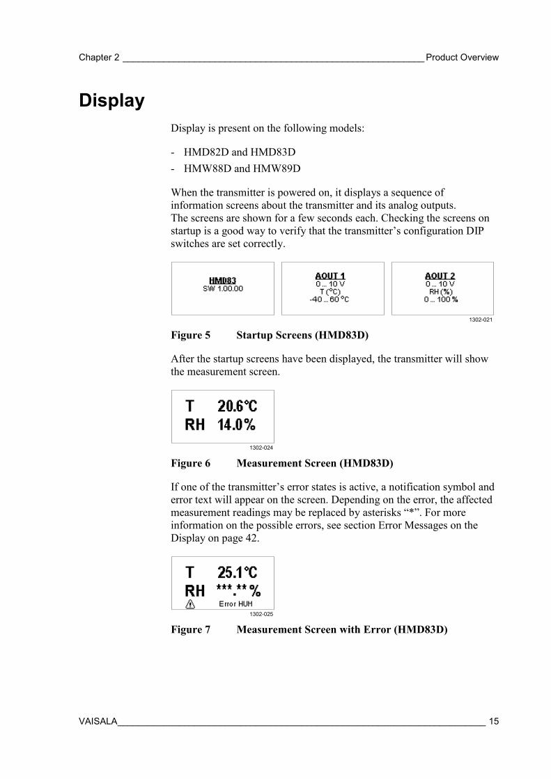
When the transmitter is powered on, it displays a sequence of information screens about the transmitter and its analog outputs. The screens are shown for a few seconds each. Checking the screens on startup is a good way to verify that the transmitter’s configuration DIP switches are set correctly.
1302-021
Figure 5 Startup Screens (HMD83D)
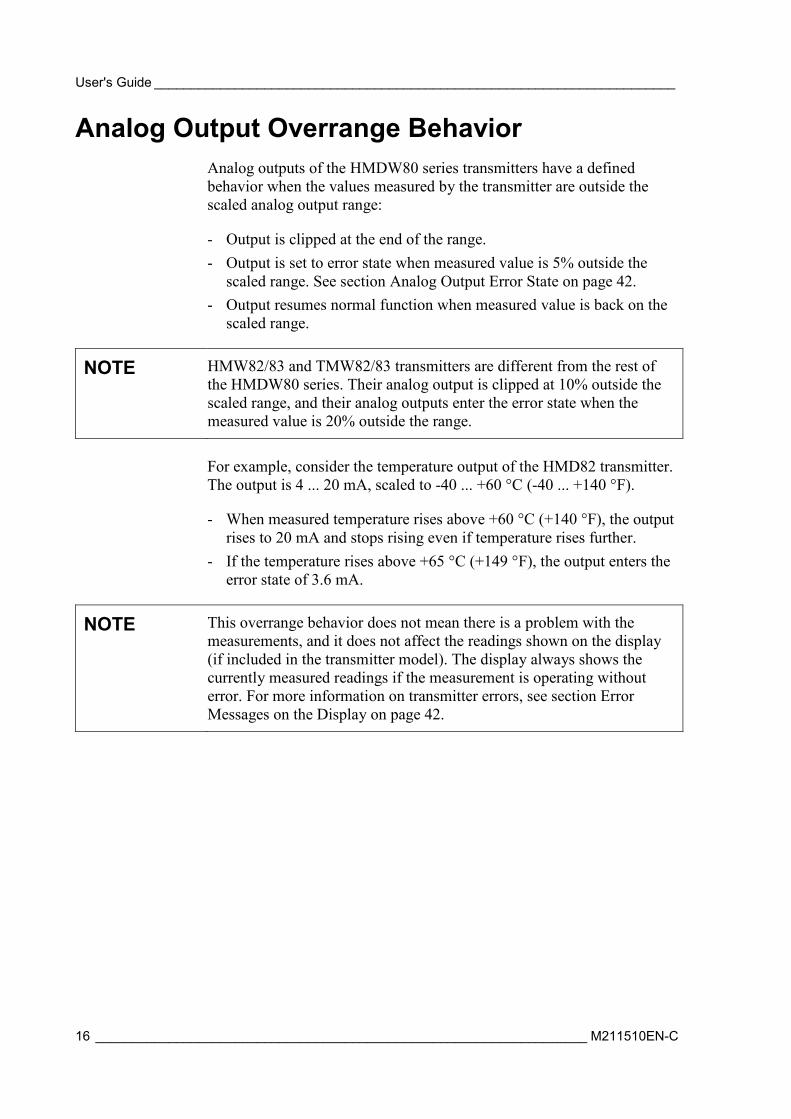
After the startup screens have been displayed, the transmitter will show the measurement screen.
1302-024
Figure 6 Measurement Screen (HMD83D)
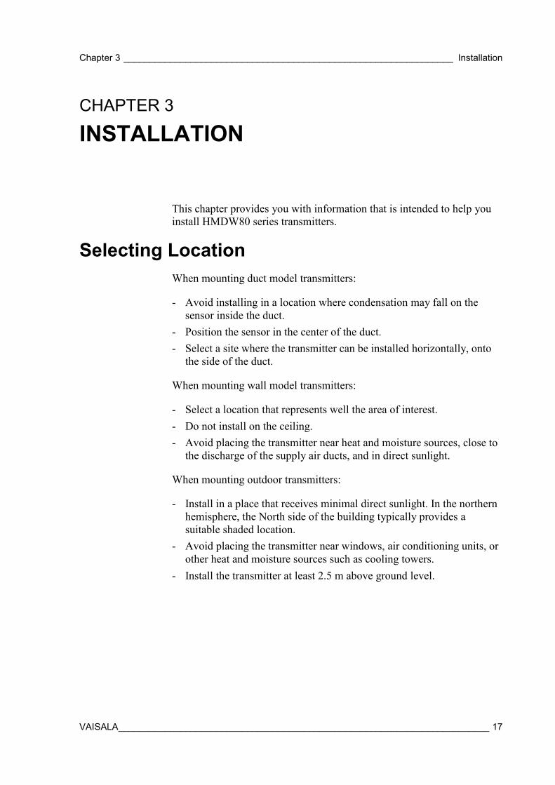
If one of the transmitter’s error states is active, a notification symbol and error text will appear on the screen. Depending on the error, the affected measurement readings may be replaced by asterisks “*”. For more information on the possible errors, see section Error Messages on the Display on page 42.
1302-025
Figure 7 Measurement Screen with Error (HMD83D)
User's Guide _______________________________________________________________________
16 ___________________________________________________________________ M211510EN-C
Analog Output Overrange Behavior Analog outputs of the HMDW80 series transmitters have a defined behavior when the values measured by the transmitter are outside the scaled analog output range:
- Output is clipped at the end of the range. - Output is set to error state when measured value is 5% outside the
scaled range. See section Analog Output Error State on page 42. - Output resumes normal function when measured value is back on the
scaled range.
NOTE HMW82/83 and TMW82/83 transmitters are different from the rest of the HMDW80 series. Their analog output is clipped at 10% outside the scaled range, and their analog outputs enter the error state when the measured value is 20% outside the range.
For example, consider the temperature output of the HMD82 transmitter. The output is 4 ... 20 mA, scaled to -40 ... +60 °C (-40 ... +140 °F).
- When measured temperature rises above +60 °C (+140 °F), the output rises to 20 mA and stops rising even if temperature rises further.
- If the temperature rises above +65 °C (+149 °F), the output enters the error state of 3.6 mA.
NOTE This overrange behavior does not mean there is a problem with the measurements, and it does not affect the readings shown on the display (if included in the transmitter model). The display always shows the currently measured readings if the measurement is operating without error. For more information on transmitter errors, see section Error Messages on the Display on page 42.
Chapter 3 ________________________________________________________________ Installation
VAISALA ________________________________________________________________________ 17
CHAPTER 3
INSTALLATION
This chapter provides you with information that is intended to help you install HMDW80 series transmitters.
Selecting Location When mounting duct model transmitters:
- Avoid installing in a location where condensation may fall on the sensor inside the duct.
- Position the sensor in the center of the duct. - Select a site where the transmitter can be installed horizontally, onto
the side of the duct.
When mounting wall model transmitters:
- Select a location that represents well the area of interest. - Do not install on the ceiling. - Avoid placing the transmitter near heat and moisture sources, close to
the discharge of the supply air ducts, and in direct sunlight.
When mounting outdoor transmitters:
- Install in a place that receives minimal direct sunlight. In the northern hemisphere, the North side of the building typically provides a suitable shaded location.
- Avoid placing the transmitter near windows, air conditioning units, or other heat and moisture sources such as cooling towers.
- Install the transmitter at least 2.5 m above ground level.
User's Guide _______________________________________________________________________
18 ___________________________________________________________________ M211510EN-C
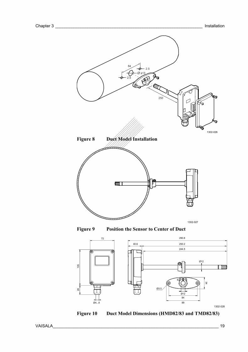
Installing Duct Models HMD82/83 and TMD82/83
REQUIRED TOOLS
- Medium size crosshead screwdriver (Pozidriv) for screws on cover and flange.
- Small slotted screwdriver for screw terminals. - Drill with 2.5 mm and 13 mm bits for making the installation
holes. - Tools for cutting and stripping wires. - 19 mm open-end wrench for tightening the cable gland.
1. Remove the yellow transport protection cap and separate the
fastening flange from the transmitter. 2. Use the flange to mark the location and size of the installation holes
on the side of the duct. 3. Drill the installation holes in the duct. Refer to Figure 8 below. 4. Secure the fastening flange to the duct with the two screws
(included). 5. Push the probe of the transmitter through the flange and into the
duct. The probe should reach far enough so that the sensor is located in the middle of the duct.
6. Secure the transmitter to the flange by tightening the screw on the flange that holds the probe in place.
7. Open the transmitter cover, and route the power and signal cable through the cable gland. Connect the wires to the screw terminals. Refer to section Wiring on page 26.
8. Check that the DIP switches (if present in your transmitter model) are set as desired. See section DIP Switches on page 30.
9. Tighten the cable gland and close the transmitter cover.
Chapter 3 ________________________________________________________________ Installation
VAISALA ________________________________________________________________________ 19
1302-026
Figure 8 Duct Model Installation
1302-027
Figure 9 Position the Sensor to Center of Duct
1302-028
Figure 10 Duct Model Dimensions (HMD82/83 and TMD82/83)
99
290.8
250.240.6
72
Ø4...8
105
Ø3.5
Ø1284
26
34
244.5
Ø12
User's Guide _______________________________________________________________________
20 ___________________________________________________________________ M211510EN-C
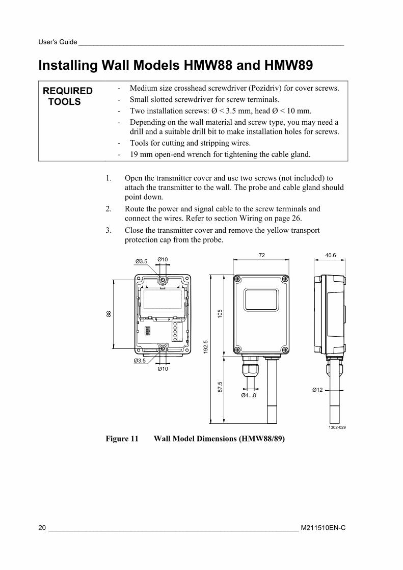
Installing Wall Models HMW88 and HMW89
REQUIRED TOOLS
- Medium size crosshead screwdriver (Pozidriv) for cover screws. - Small slotted screwdriver for screw terminals. - Two installation screws: Ø < 3.5 mm, head Ø < 10 mm. - Depending on the wall material and screw type, you may need a
drill and a suitable drill bit to make installation holes for screws. - Tools for cutting and stripping wires. - 19 mm open-end wrench for tightening the cable gland.
1. Open the transmitter cover and use two screws (not included) to
attach the transmitter to the wall. The probe and cable gland should point down.
2. Route the power and signal cable to the screw terminals and connect the wires. Refer to section Wiring on page 26.
3. Close the transmitter cover and remove the yellow transport protection cap from the probe.
1302-029
Figure 11 Wall Model Dimensions (HMW88/89)
88
Ø3.5
Ø10Ø3.5
Ø10
192.
5
72 40.6
Ø4...8
105
87.5
Ø12
Chapter 3 ________________________________________________________________ Installation
VAISALA ________________________________________________________________________ 21
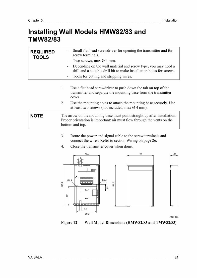
Installing Wall Models HMW82/83 and TMW82/83
REQUIRED TOOLS
- Small flat head screwdriver for opening the transmitter and for screw terminals.
- Two screws, max Ø 4 mm. - Depending on the wall material and screw type, you may need a
drill and a suitable drill bit to make installation holes for screws. - Tools for cutting and stripping wires.
1. Use a flat head screwdriver to push down the tab on top of the
transmitter and separate the mounting base from the transmitter cover.
2. Use the mounting holes to attach the mounting base securely. Use at least two screws (not included, max Ø 4 mm).
NOTE The arrow on the mounting base must point straight up after installation. Proper orientation is important: air must flow through the vents on the bottom and top.
3. Route the power and signal cable to the screw terminals and
connect the wires. Refer to section Wiring on page 26. 4. Close the transmitter cover when done.
1302-030
Figure 12 Wall Model Dimensions (HMW82/83 and TMW82/83)
76.9
123.
7
95
5.5
81
127.
3
60.3
59
Ø4.4 Ø4.4
2032.4
24
User's Guide _______________________________________________________________________
22 ___________________________________________________________________ M211510EN-C
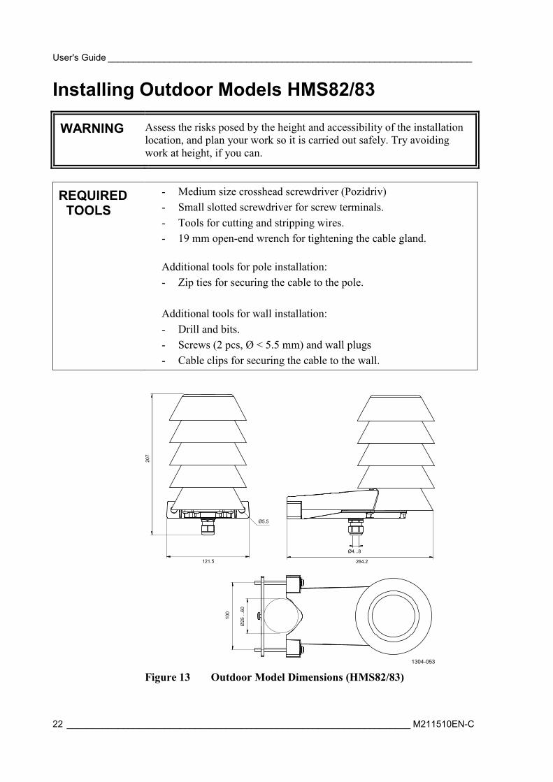
Installing Outdoor Models HMS82/83
WARNING Assess the risks posed by the height and accessibility of the installation location, and plan your work so it is carried out safely. Try avoiding work at height, if you can.
REQUIRED TOOLS
- Medium size crosshead screwdriver (Pozidriv) - Small slotted screwdriver for screw terminals. - Tools for cutting and stripping wires. - 19 mm open-end wrench for tightening the cable gland. Additional tools for pole installation: - Zip ties for securing the cable to the pole.
Additional tools for wall installation: - Drill and bits. - Screws (2 pcs, Ø < 5.5 mm) and wall plugs - Cable clips for securing the cable to the wall.
1304-053
Figure 13 Outdoor Model Dimensions (HMS82/83)
207
264.2121.5
Ø5.5
Ø4...8
Ø25
...6
0
100
Chapter 3 ________________________________________________________________ Installation
VAISALA ________________________________________________________________________ 23
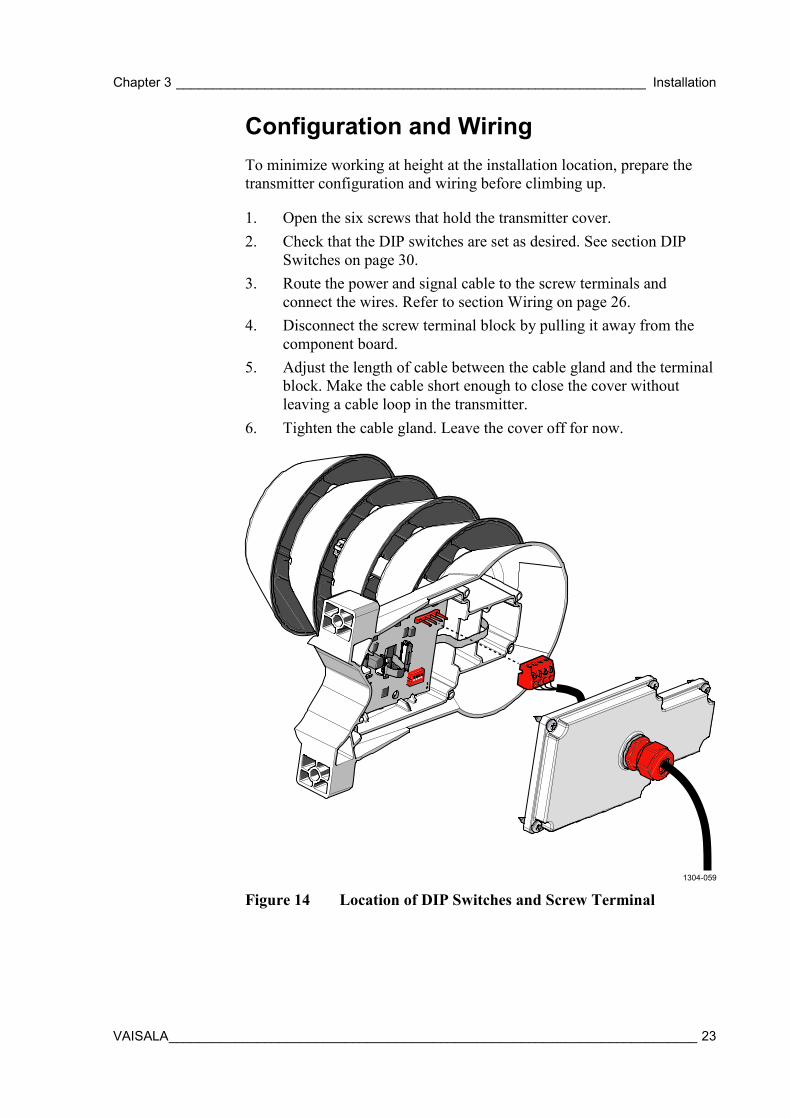
Configuration and Wiring To minimize working at height at the installation location, prepare the transmitter configuration and wiring before climbing up.
1. Open the six screws that hold the transmitter cover. 2. Check that the DIP switches are set as desired. See section DIP
Switches on page 30. 3. Route the power and signal cable to the screw terminals and
connect the wires. Refer to section Wiring on page 26. 4. Disconnect the screw terminal block by pulling it away from the
component board. 5. Adjust the length of cable between the cable gland and the terminal
block. Make the cable short enough to close the cover without leaving a cable loop in the transmitter.
6. Tighten the cable gland. Leave the cover off for now.
1304-059
Figure 14 Location of DIP Switches and Screw Terminal
User's Guide _______________________________________________________________________
24 ___________________________________________________________________ M211510EN-C
Pole installation
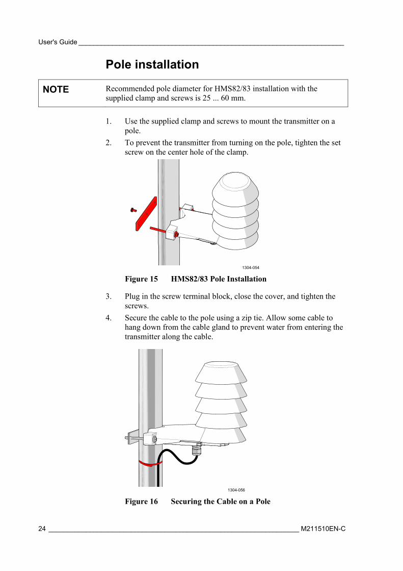
NOTE Recommended pole diameter for HMS82/83 installation with the supplied clamp and screws is 25 ... 60 mm.
1. Use the supplied clamp and screws to mount the transmitter on a
pole. 2. To prevent the transmitter from turning on the pole, tighten the set
screw on the center hole of the clamp.
1304-054
Figure 15 HMS82/83 Pole Installation
3. Plug in the screw terminal block, close the cover, and tighten the screws.
4. Secure the cable to the pole using a zip tie. Allow some cable to hang down from the cable gland to prevent water from entering the transmitter along the cable.
1304-056
Figure 16 Securing the Cable on a Pole
Chapter 3 ________________________________________________________________ Installation
VAISALA ________________________________________________________________________ 25
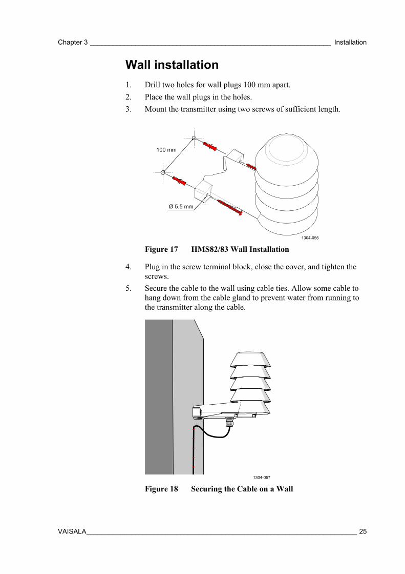
Wall installation 1. Drill two holes for wall plugs 100 mm apart. 2. Place the wall plugs in the holes. 3. Mount the transmitter using two screws of sufficient length.
1304-055
Figure 17 HMS82/83 Wall Installation
4. Plug in the screw terminal block, close the cover, and tighten the screws.
5. Secure the cable to the wall using cable ties. Allow some cable to hang down from the cable gland to prevent water from running to the transmitter along the cable.
1304-057
Figure 18 Securing the Cable on a Wall
100 mm
Ø 5.5 mm
User's Guide _______________________________________________________________________
26 ___________________________________________________________________ M211510EN-C
Wiring
WARNING Connect only de-energized wires.
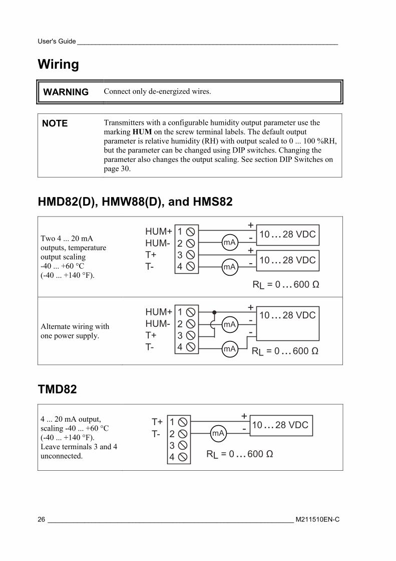
NOTE Transmitters with a configurable humidity output parameter use the marking HUM on the screw terminal labels. The default output parameter is relative humidity (RH) with output scaled to 0 ... 100 %RH, but the parameter can be changed using DIP switches. Changing the parameter also changes the output scaling. See section DIP Switches on page 30.
HMD82(D), HMW88(D), and HMS82
Two 4 ... 20 mA outputs, temperature output scaling -40 ... +60 °C (-40 ... +140 °F).
Alternate wiring with one power supply.
TMD82
4 ... 20 mA output, scaling -40 ... +60 °C (-40 ... +140 °F). Leave terminals 3 and 4 unconnected.
HUM-T+T-
HUM+234
1 10...28 VDCmA
mA
+-+- 10...28 VDC
RL = 0 ...600 Ω
mA
mA
+--
RL = 0 ...600 Ω
10...28 VDCHUM-T+T-
HUM+234
1
mA
+-
RL = 0 ...600 Ω
T-T+
234
1 10...28 VDC
Chapter 3 ________________________________________________________________ Installation
VAISALA ________________________________________________________________________ 27
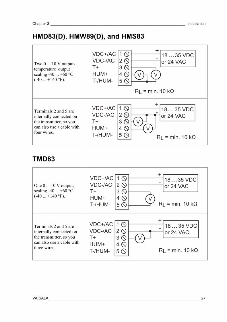
HMD83(D), HMW89(D), and HMS83
Two 0 ... 10 V outputs, temperature output scaling -40 ... +60 °C (-40 ... +140 °F).
Terminals 2 and 5 are internally connected on the transmitter, so you can also use a cable with four wires.
TMD83
One 0 ... 10 V output, scaling -40 ... +60 °C (-40 ... +140 °F).
Terminals 2 and 5 are internally connected on the transmitter, so you can also use a cable with three wires.
V V
+- 18...35 VDC
or 24 VACVDC-/ACT+HUM+
VDC+/AC234
1
5T-/HUM-
RL = min. 10 kΩ
VV
+- 18...35 VDC
or 24 VACVDC-/ACT+HUM+
VDC+/AC234
1
5T-/HUM- RL = min. 10 kΩ
+-
V
VDC-/ACT+HUM+
VDC+/AC234
1 18...35 VDCor 24 VAC
5T-/HUM- RL = min. 10 kΩ
+-
VVDC-/ACT+HUM+
VDC+/AC234
1 18...35 VDCor 24 VAC
5T-/HUM- RL = min. 10 kΩ

User's Guide _______________________________________________________________________
28 ___________________________________________________________________ M211510EN-C
HMW82
Two 4 ... 20 mA outputs, temperature output scaling -5 ... +55 °C (+23 ... +131 °F). You must connect the RH channel of the HMW82, even if you only want to measure temperature. Connecting the T channel is optional.
TMW82
One 4 ... 20 mA output, scaling -5 ... +55 °C (+23 ... +131 °F).
Leave the two terminals on the left unconnected.
-T -RH+T +RH
10...28 VDC+-
10...28 VDC+-
mA
mA
RL = 0 ...600 Ω
-T +T
10...28 VDC+-mA
RL = 0 ...600 Ω
Chapter 3 ________________________________________________________________ Installation
VAISALA ________________________________________________________________________ 29
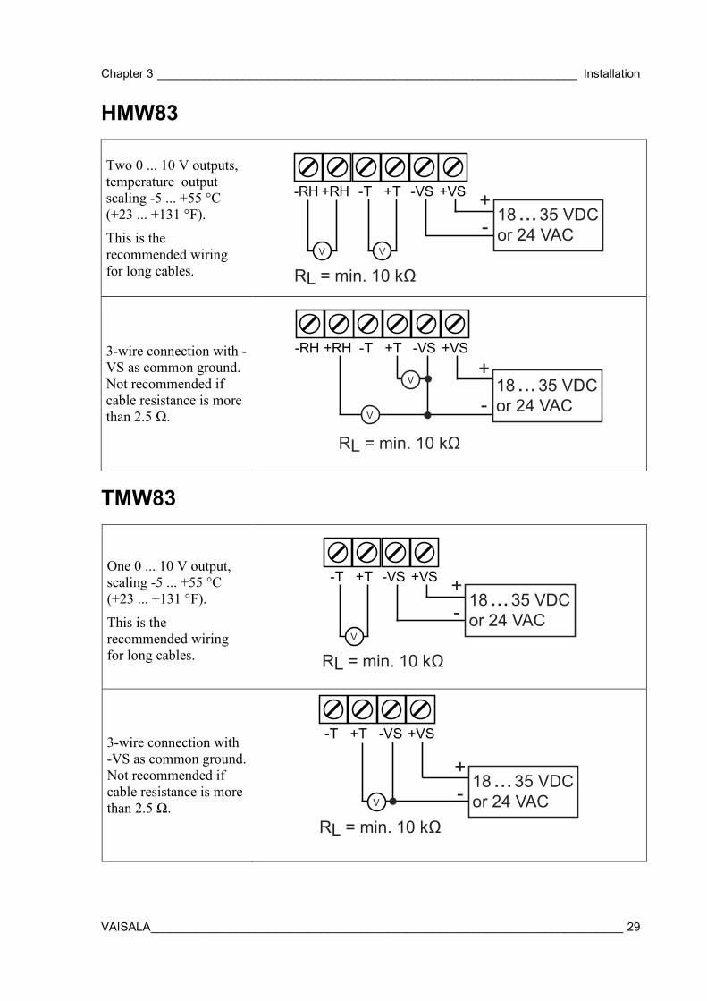
HMW83
Two 0 ... 10 V outputs, temperature output scaling -5 ... +55 °C (+23 ... +131 °F).
This is the recommended wiring for long cables.
3-wire connection with -VS as common ground. Not recommended if cable resistance is more than 2.5 Ω.
TMW83
One 0 ... 10 V output, scaling -5 ... +55 °C (+23 ... +131 °F).
This is the recommended wiring for long cables.
3-wire connection with -VS as common ground. Not recommended if cable resistance is more than 2.5 Ω.
-T -VS+T +VS-RH +RH +- 18...35 VDC
or 24 VAC
RL = min. 10 kΩV V
-T -VS+T +VS-RH +RH+
-18...35 VDCor 24 VAC
V
V
RL = min. 10 kΩ
-T -VS+T +VS +- 18...35 VDC
or 24 VAC
RL = min. 10 kΩV
-T -VS+T +VS
RL = min. 10 kΩV
+- 18...35 VDC
or 24 VAC
User's Guide _______________________________________________________________________
30 ___________________________________________________________________ M211510EN-C
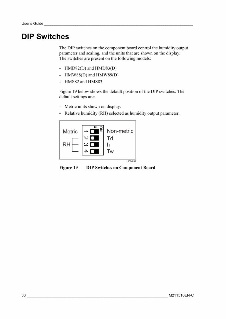
DIP Switches The DIP switches on the component board control the humidity output parameter and scaling, and the units that are shown on the display. The switches are present on the following models:
- HMD82(D) and HMD83(D) - HMW88(D) and HMW89(D) - HMS82 and HMS83
Figure 19 below shows the default position of the DIP switches. The default settings are:
- Metric units shown on display. - Relative humidity (RH) selected as humidity output parameter.
1302-053
Figure 19 DIP Switches on Component Board
12
34
Metric
RH
Non-metricTdhTw
ON
Chapter 3 ________________________________________________________________ Installation
VAISALA ________________________________________________________________________ 31
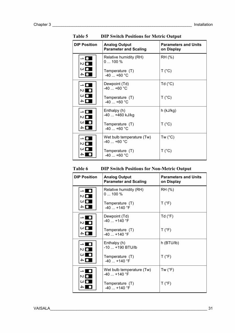
Table 5 DIP Switch Positions for Metric Output
DIP Position Analog Output Parameter and Scaling
Parameters and Units on Display
Relative humidity (RH) 0 ... 100 % Temperature (T) -40 ... +60 °C
RH (%) T (°C)
Dewpoint (Td) -40 ... +60 °C Temperature (T) -40 ... +60 °C
Td (°C) T (°C)
Enthalpy (h) -40 ... +460 kJ/kg Temperature (T) -40 ... +60 °C
h (kJ/kg) T (°C)
Wet bulb temperature (Tw) -40 ... +60 °C Temperature (T) -40 ... +60 °C
Tw (°C) T (°C)
Table 6 DIP Switch Positions for Non-Metric Output
DIP Position Analog Output Parameter and Scaling
Parameters and Units on Display
Relative humidity (RH) 0 ... 100 % Temperature (T) -40 ... +140 °F
RH (%) T (°F)
Dewpoint (Td) -40 ... +140 °F Temperature (T) -40 ... +140 °F
Td (°F) T (°F)
Enthalpy (h) -10 ... +190 BTU/lb Temperature (T) -40 ... +140 °F
h (BTU/lb) T (°F)
Wet bulb temperature (Tw) -40 ... +140 °F Temperature (T) -40 ... +140 °F
Tw (°F) T (°F)
12
34
12
34
12
34
12
34
12
34
12
34
12
34
12
34

User's Guide _______________________________________________________________________
32 ___________________________________________________________________ M211510EN-C
This page intentionally left blank.
Chapter 4 _______________________________________________________________ Maintenance
VAISALA ________________________________________________________________________ 33
CHAPTER 4
MAINTENANCE
This chapter provides information that is needed in basic maintenance of HMDW80 series.
Cleaning The body of the transmitter can be cleaned by wiping with a moistened lint-free cloth. Do not use cleaning agents or solvents, or blow pressurized air into the transmitter housing or on the filter.
NOTE Do not attempt to clean contaminated INTERCAP® sensors or filters. Instead, replace them with new parts. Filters and sensors can be purchased from Vaisala. For order codes, see section Spare Parts and Accessories on page 48.
Calibration You can verify the performance of your HMDW80 series transmitter by comparing its reading with the reading from a portable reference instrument such as the HM70 Hand-Held Humidity and Temperature Meter. For operating instructions, refer to the documentation of your reference instrument.
If the comparison indicates that the reading from the transmitter is not within specification, the transmitter may need to have its filter and sensor replaced.
User's Guide _______________________________________________________________________
34 ___________________________________________________________________ M211510EN-C
Replacing the INTERCAP® Humidity Sensor HMDW80 series transmitters use the Vaisala INTERCAP® sensor for humidity measurement. The INTERCAP® sensor is designed to be replaced when necessary, and does not require adjustment by the user.
Replacing the INTERCAP® Sensor on Models HMD82/83 and HMW88/89
REQUIRED TOOLS
- New INTERCAP® humidity sensor. - New filter (always recommended when replacing the sensor). - Duct models only: medium size crosshead screwdriver (Pozidriv).
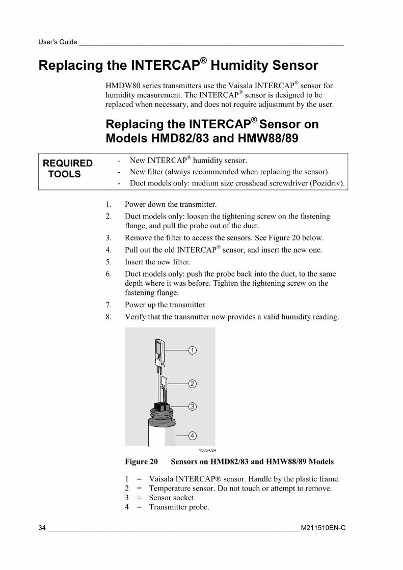
1. Power down the transmitter. 2. Duct models only: loosen the tightening screw on the fastening
flange, and pull the probe out of the duct. 3. Remove the filter to access the sensors. See Figure 20 below. 4. Pull out the old INTERCAP® sensor, and insert the new one. 5. Insert the new filter. 6. Duct models only: push the probe back into the duct, to the same
depth where it was before. Tighten the tightening screw on the fastening flange.
7. Power up the transmitter. 8. Verify that the transmitter now provides a valid humidity reading.
1305-024
Figure 20 Sensors on HMD82/83 and HMW88/89 Models
1 = Vaisala INTERCAP® sensor. Handle by the plastic frame. 2 = Temperature sensor. Do not touch or attempt to remove. 3 = Sensor socket. 4 = Transmitter probe.
1
2
3
4
Chapter 4 _______________________________________________________________ Maintenance
VAISALA ________________________________________________________________________ 35
Replacing the INTERCAP® Sensor on Wall Models HMW82/83
REQUIRED TOOLS
- New INTERCAP® humidity sensor. - Small flat head screwdriver.
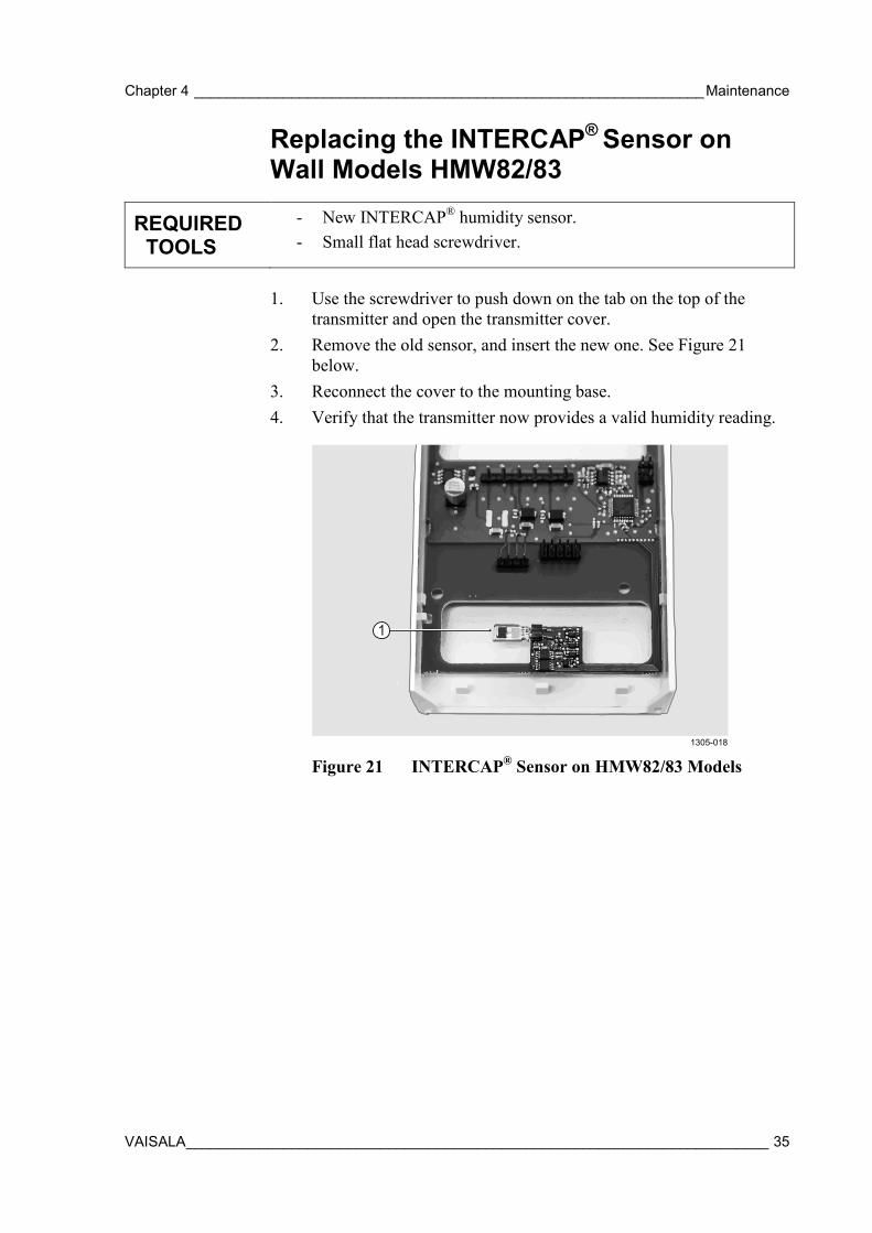
1. Use the screwdriver to push down on the tab on the top of the
transmitter and open the transmitter cover. 2. Remove the old sensor, and insert the new one. See Figure 21
below. 3. Reconnect the cover to the mounting base. 4. Verify that the transmitter now provides a valid humidity reading.
1305-018
Figure 21 INTERCAP® Sensor on HMW82/83 Models
1
User's Guide _______________________________________________________________________
36 ___________________________________________________________________ M211510EN-C
Replacing the INTERCAP® Sensor on Outdoor Models HMS82/83
REQUIRED TOOLS
- New INTERCAP® humidity sensor. - New filter (always recommended when replacing the sensor). - Medium size crosshead screwdriver (Pozidriv) - Flat head screwdriver - 3 mm hex key (Allen key) for opening the radiation shield screws. - If transmitter mounted on pole: 2.5 mm hex key for opening and
tightening the set screw.
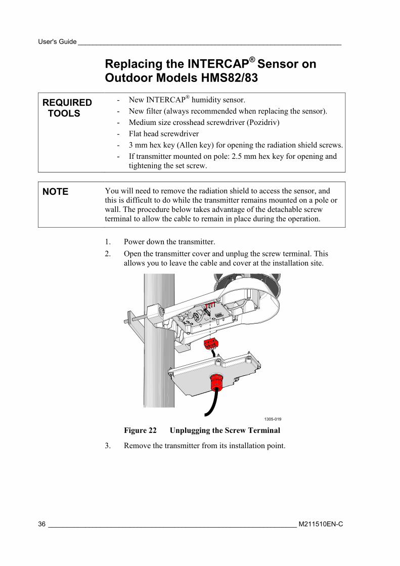
NOTE You will need to remove the radiation shield to access the sensor, and this is difficult to do while the transmitter remains mounted on a pole or wall. The procedure below takes advantage of the detachable screw terminal to allow the cable to remain in place during the operation.
1. Power down the transmitter. 2. Open the transmitter cover and unplug the screw terminal. This
allows you to leave the cable and cover at the installation site.
1305-019
Figure 22 Unplugging the Screw Terminal
3. Remove the transmitter from its installation point.
Chapter 4 _______________________________________________________________ Maintenance
VAISALA ________________________________________________________________________ 37
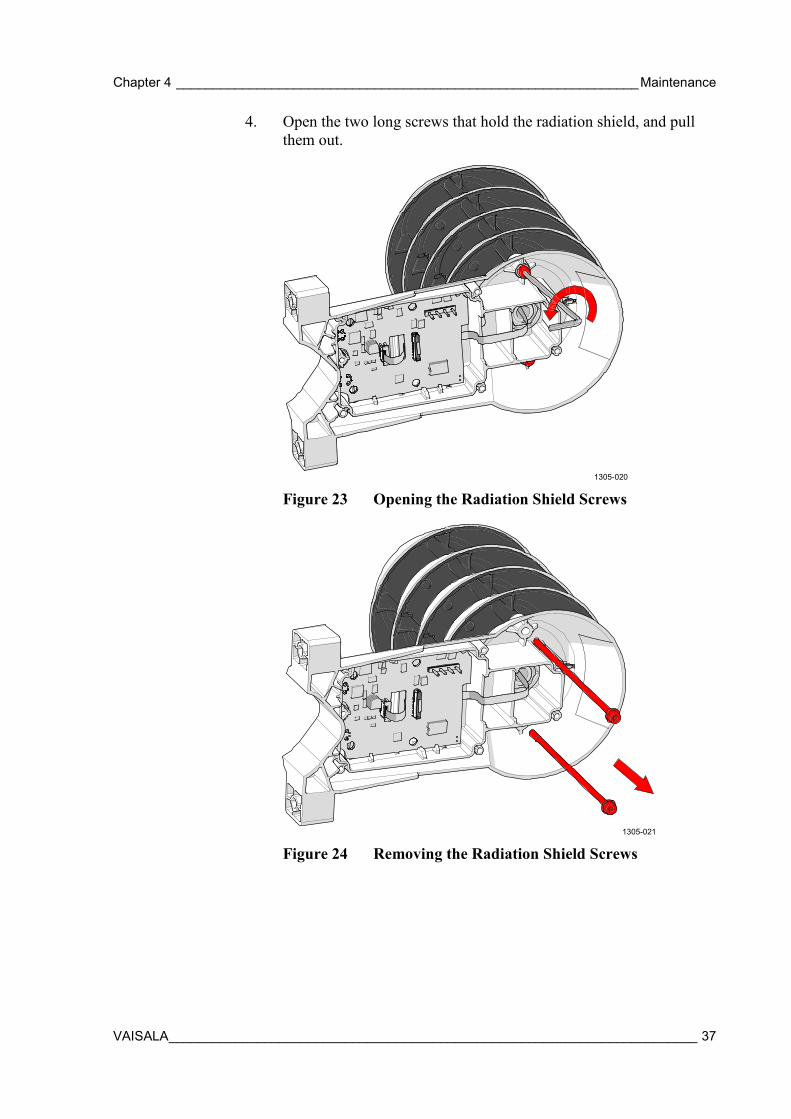
4. Open the two long screws that hold the radiation shield, and pull them out.
1305-020
Figure 23 Opening the Radiation Shield Screws
1305-021
Figure 24 Removing the Radiation Shield Screws
User's Guide _______________________________________________________________________
38 ___________________________________________________________________ M211510EN-C
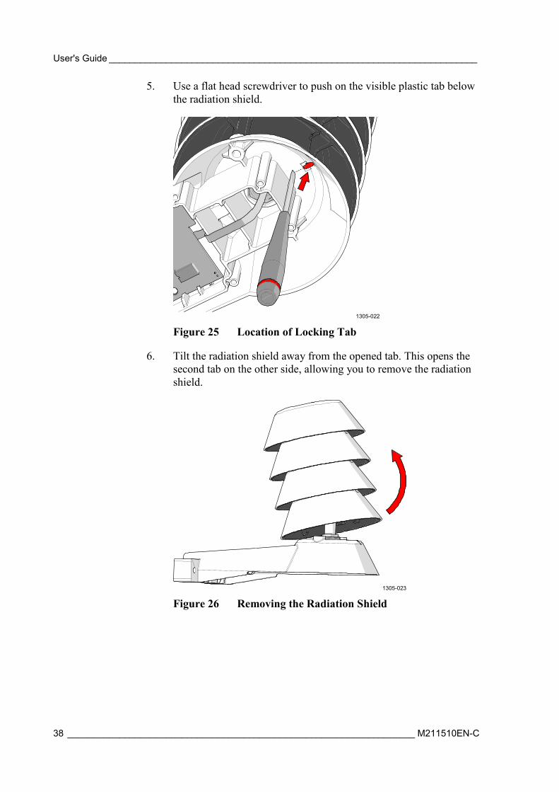
5. Use a flat head screwdriver to push on the visible plastic tab below the radiation shield.
1305-022
Figure 25 Location of Locking Tab
6. Tilt the radiation shield away from the opened tab. This opens the second tab on the other side, allowing you to remove the radiation shield.
1305-023
Figure 26 Removing the Radiation Shield
Chapter 4 _______________________________________________________________ Maintenance
VAISALA ________________________________________________________________________ 39
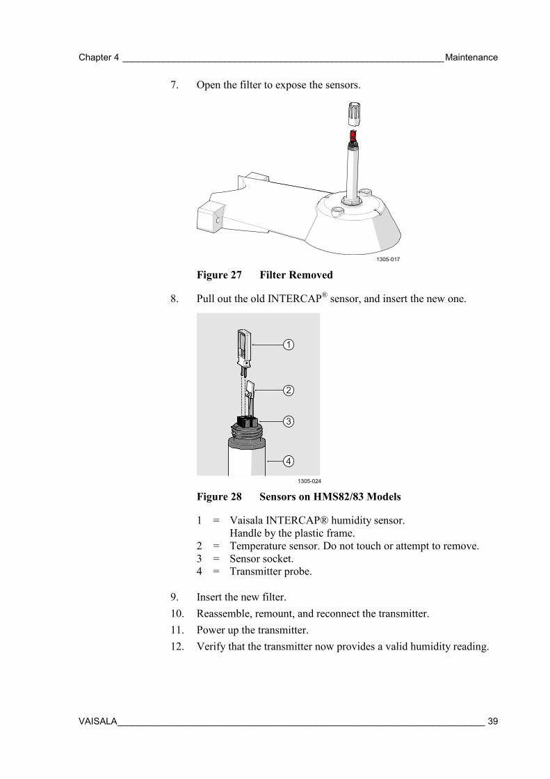
7. Open the filter to expose the sensors.
1305-017
Figure 27 Filter Removed
8. Pull out the old INTERCAP® sensor, and insert the new one.
1305-024
Figure 28 Sensors on HMS82/83 Models
1 = Vaisala INTERCAP® humidity sensor. Handle by the plastic frame.
2 = Temperature sensor. Do not touch or attempt to remove. 3 = Sensor socket. 4 = Transmitter probe.
9. Insert the new filter. 10. Reassemble, remount, and reconnect the transmitter. 11. Power up the transmitter. 12. Verify that the transmitter now provides a valid humidity reading.
1
2
3
4

User's Guide _______________________________________________________________________
40 ___________________________________________________________________ M211510EN-C
This page intentionally left blank.
Chapter 5 ____________________________________________________________ Troubleshooting
VAISALA ________________________________________________________________________ 41
CHAPTER 5
TROUBLESHOOTING
This chapter describes possible problems, their probable causes and remedies, and provides contact information for technical support.
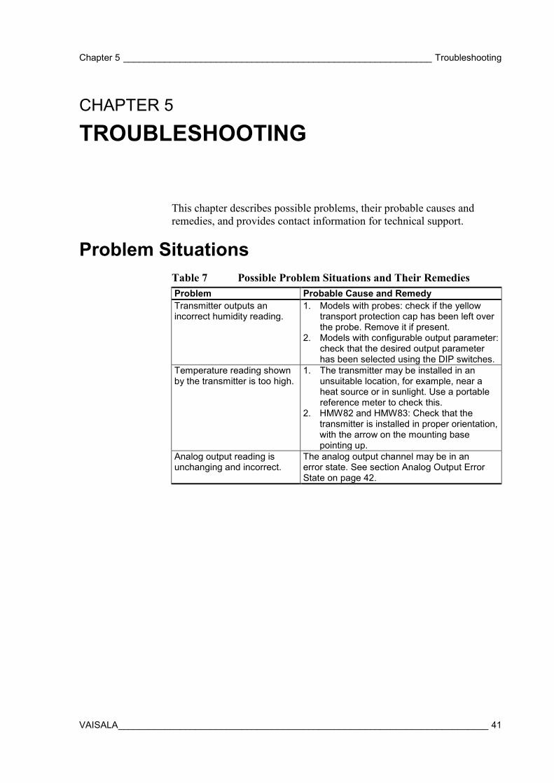
Problem Situations Table 7 Possible Problem Situations and Their Remedies Problem Probable Cause and Remedy Transmitter outputs an incorrect humidity reading.
1. Models with probes: check if the yellow transport protection cap has been left over the probe. Remove it if present.
2. Models with configurable output parameter: check that the desired output parameter has been selected using the DIP switches.
Temperature reading shown by the transmitter is too high.
1. The transmitter may be installed in an unsuitable location, for example, near a heat source or in sunlight. Use a portable reference meter to check this.
2. HMW82 and HMW83: Check that the transmitter is installed in proper orientation, with the arrow on the mounting base pointing up.
Analog output reading is unchanging and incorrect.
The analog output channel may be in an error state. See section Analog Output Error State on page 42.
User's Guide _______________________________________________________________________
42 ___________________________________________________________________ M211510EN-C
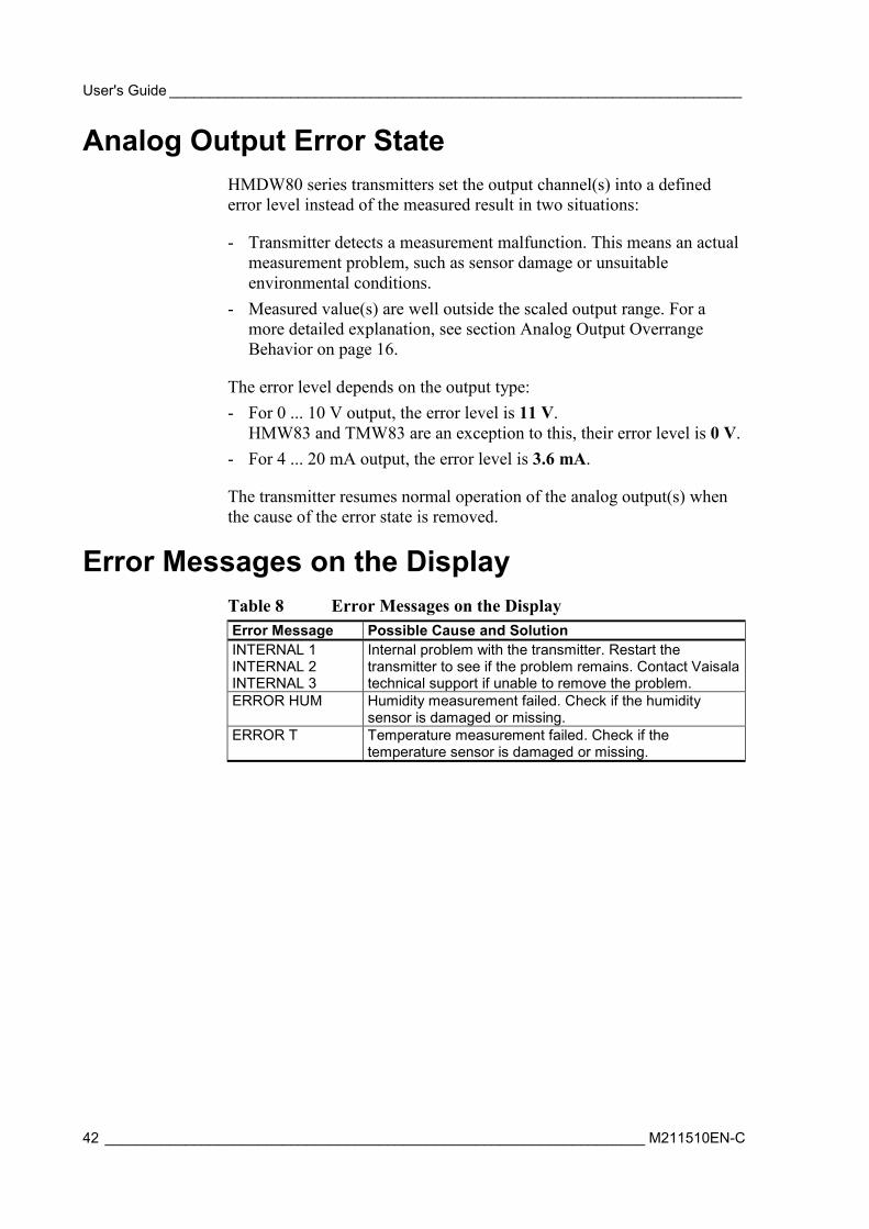
Analog Output Error State HMDW80 series transmitters set the output channel(s) into a defined error level instead of the measured result in two situations:
- Transmitter detects a measurement malfunction. This means an actual measurement problem, such as sensor damage or unsuitable environmental conditions.
- Measured value(s) are well outside the scaled output range. For a more detailed explanation, see section Analog Output Overrange Behavior on page 16.
The error level depends on the output type: - For 0 ... 10 V output, the error level is 11 V.
HMW83 and TMW83 are an exception to this, their error level is 0 V. - For 4 ... 20 mA output, the error level is 3.6 mA.
The transmitter resumes normal operation of the analog output(s) when the cause of the error state is removed.
Error Messages on the Display Table 8 Error Messages on the Display Error Message Possible Cause and Solution INTERNAL 1 INTERNAL 2 INTERNAL 3
Internal problem with the transmitter. Restart the transmitter to see if the problem remains. Contact Vaisala technical support if unable to remove the problem.
ERROR HUM Humidity measurement failed. Check if the humidity sensor is damaged or missing.
ERROR T Temperature measurement failed. Check if the temperature sensor is damaged or missing.
Chapter 5 ____________________________________________________________ Troubleshooting
VAISALA ________________________________________________________________________ 43
Technical Support For technical questions, contact the Vaisala technical support by e-mail at [email protected]. Provide at least the following supporting information:
- Name and model of the product in question - Serial number of the product - Name and location of the installation site - Name and contact information of a technically competent person who
can provide further information on the problem.
Product Returns If the product must be returned for service, see www.vaisala.com/returns.
For contact information of Vaisala Service Centers, see www.vaisala.com/servicecenters.

User's Guide _______________________________________________________________________
44 ___________________________________________________________________ M211510EN-C
This page intentionally left blank.
Chapter 6 _____________________________________________________________ Technical Data
VAISALA ________________________________________________________________________ 45
CHAPTER 6
TECHNICAL DATA
This chapter provides the technical data of the HMDW80 series.
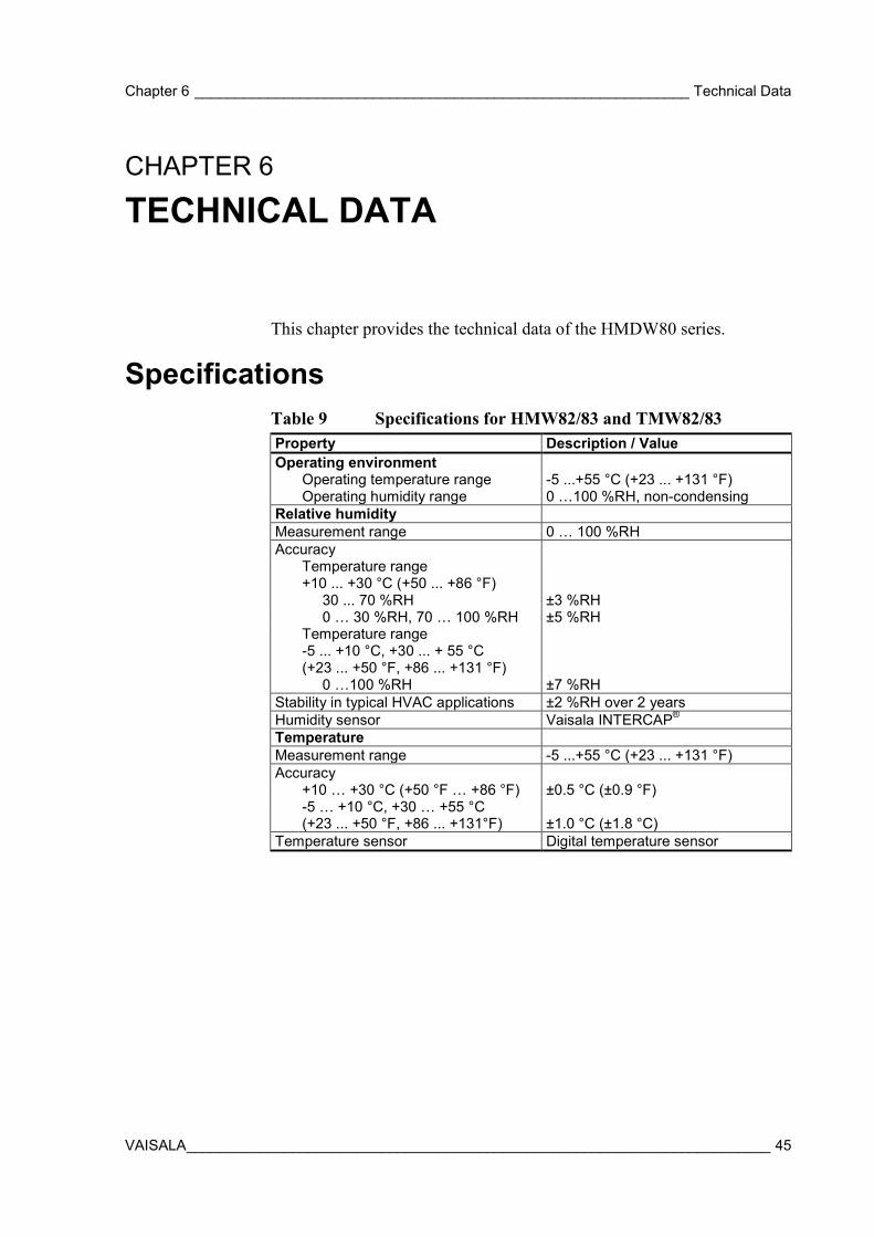
Specifications Table 9 Specifications for HMW82/83 and TMW82/83 Property Description / Value Operating environment Operating temperature range -5 ...+55 °C (+23 ... +131 °F) Operating humidity range 0 …100 %RH, non-condensing Relative humidity Measurement range 0 … 100 %RH Accuracy Temperature range
+10 ... +30 °C (+50 ... +86 °F) 30 ... 70 %RH ±3 %RH 0 … 30 %RH, 70 … 100 %RH ±5 %RH Temperature range
-5 ... +10 °C, +30 ... + 55 °C (+23 ... +50 °F, +86 ... +131 °F)
0 …100 %RH ±7 %RH Stability in typical HVAC applications ±2 %RH over 2 years Humidity sensor Vaisala INTERCAP® Temperature Measurement range -5 ...+55 °C (+23 ... +131 °F) Accuracy +10 … +30 °C (+50 °F … +86 °F) ±0.5 °C (±0.9 °F) -5 … +10 °C, +30 … +55 °C
(+23 ... +50 °F, +86 ... +131°F) ±1.0 °C (±1.8 °C) Temperature sensor Digital temperature sensor
User's Guide _______________________________________________________________________
46 ___________________________________________________________________ M211510EN-C
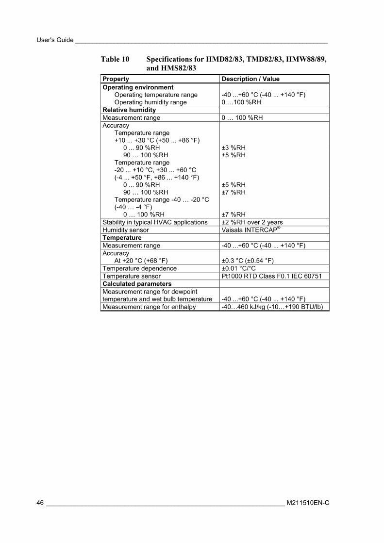
Table 10 Specifications for HMD82/83, TMD82/83, HMW88/89, and HMS82/83
Property Description / Value Operating environment Operating temperature range -40 ...+60 °C (-40 ... +140 °F) Operating humidity range 0 …100 %RH Relative humidity Measurement range 0 … 100 %RH Accuracy Temperature range
+10 ... +30 °C (+50 ... +86 °F) 0 ... 90 %RH ±3 %RH 90 … 100 %RH ±5 %RH Temperature range
-20 ... +10 °C, +30 ... +60 °C (-4 ... +50 °F, +86 ... +140 °F)
0 ... 90 %RH ±5 %RH 90 … 100 %RH ±7 %RH Temperature range -40 … -20 °C
(-40 … -4 °F) 0 … 100 %RH ±7 %RH Stability in typical HVAC applications ±2 %RH over 2 years Humidity sensor Vaisala INTERCAP® Temperature Measurement range -40 ...+60 °C (-40 ... +140 °F) Accuracy At +20 °C (+68 °F) ±0.3 °C (±0.54 °F) Temperature dependence ±0.01 °C/°C Temperature sensor Pt1000 RTD Class F0.1 IEC 60751 Calculated parameters Measurement range for dewpoint temperature and wet bulb temperature -40 ...+60 °C (-40 ... +140 °F) Measurement range for enthalpy -40…460 kJ/kg (-10…+190 BTU/lb)
Chapter 6 _____________________________________________________________ Technical Data
VAISALA ________________________________________________________________________ 47
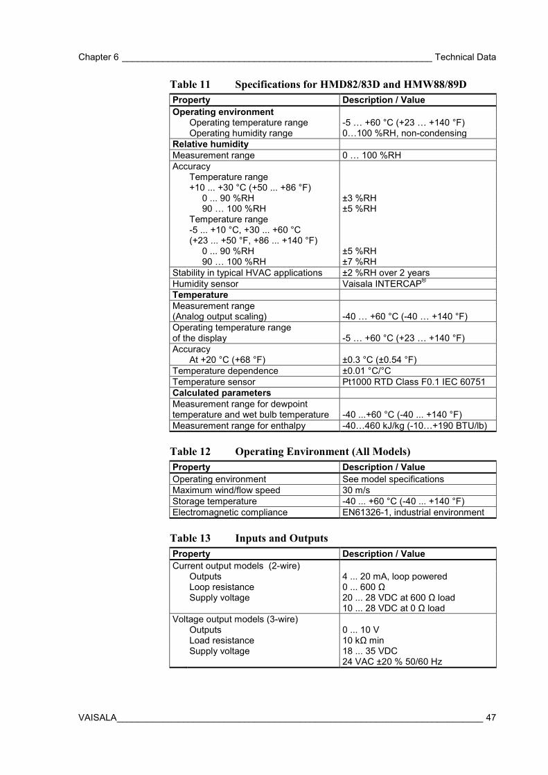
Table 11 Specifications for HMD82/83D and HMW88/89D Property Description / Value Operating environment Operating temperature range -5 … +60 °C (+23 … +140 °F) Operating humidity range 0…100 %RH, non-condensing Relative humidity Measurement range 0 … 100 %RH Accuracy Temperature range
+10 ... +30 °C (+50 ... +86 °F) 0 ... 90 %RH ±3 %RH 90 … 100 %RH ±5 %RH Temperature range
-5 ... +10 °C, +30 ... +60 °C (+23 ... +50 °F, +86 ... +140 °F)
0 ... 90 %RH ±5 %RH 90 … 100 %RH ±7 %RH Stability in typical HVAC applications ±2 %RH over 2 years Humidity sensor Vaisala INTERCAP® Temperature Measurement range (Analog output scaling) -40 … +60 °C (-40 … +140 °F) Operating temperature range of the display -5 … +60 °C (+23 … +140 °F) Accuracy At +20 °C (+68 °F) ±0.3 °C (±0.54 °F) Temperature dependence ±0.01 °C/°C Temperature sensor Pt1000 RTD Class F0.1 IEC 60751 Calculated parameters Measurement range for dewpoint temperature and wet bulb temperature -40 ...+60 °C (-40 ... +140 °F) Measurement range for enthalpy -40…460 kJ/kg (-10…+190 BTU/lb) Table 12 Operating Environment (All Models) Property Description / Value Operating environment See model specifications Maximum wind/flow speed 30 m/s Storage temperature -40 ... +60 °C (-40 ... +140 °F) Electromagnetic compliance EN61326-1, industrial environment Table 13 Inputs and Outputs Property Description / Value Current output models (2-wire) Outputs 4 ... 20 mA, loop powered Loop resistance 0 ... 600 Ω Supply voltage 20 ... 28 VDC at 600 Ω load
10 ... 28 VDC at 0 Ω load Voltage output models (3-wire) Outputs 0 ... 10 V Load resistance 10 kΩ min Supply voltage 18 ... 35 VDC
24 VAC ±20 % 50/60 Hz
User's Guide _______________________________________________________________________
48 ___________________________________________________________________ M211510EN-C
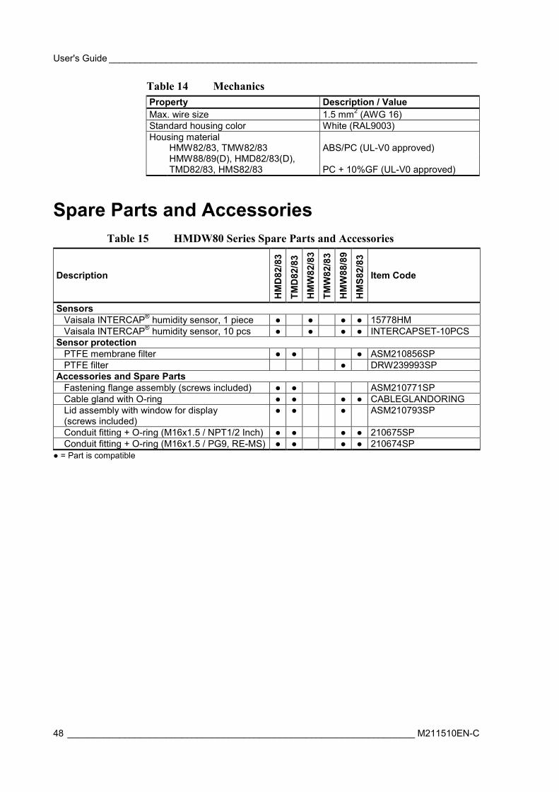
Table 14 Mechanics Property Description / Value Max. wire size 1.5 mm2 (AWG 16) Standard housing color White (RAL9003) Housing material HMW82/83, TMW82/83 ABS/PC (UL-V0 approved) HMW88/89(D), HMD82/83(D),
TMD82/83, HMS82/83 PC + 10%GF (UL-V0 approved)
Spare Parts and Accessories Table 15 HMDW80 Series Spare Parts and Accessories
Description H
MD
82/8
3
TMD
82/8
3
HM
W82
/83
TMW
82/8
3
HM
W88
/89
HM
S82/
83
Item Code
Sensors Vaisala INTERCAP® humidity sensor, 1 piece 15778HM Vaisala INTERCAP® humidity sensor, 10 pcs INTERCAPSET-10PCS Sensor protection PTFE membrane filter ASM210856SP PTFE filter DRW239993SP Accessories and Spare Parts Fastening flange assembly (screws included) ASM210771SP Cable gland with O-ring CABLEGLANDORING Lid assembly with window for display (screws included)
ASM210793SP
Conduit fitting + O-ring (M16x1.5 / NPT1/2 Inch) 210675SP Conduit fitting + O-ring (M16x1.5 / PG9, RE-MS) 210674SP
= Part is compatible

www.vaisala.com
*M211510EN*